

Page 1
Page 2
Page 3

EPA07/10 DD PLATFORM WORKSHOP MANUAL - ENGINE
TABLE OF CONTENTS
1 ROCKER COVER
1.1 DESCRIPTION AND OPERATIONOFROCKER COVER AND RELATED
PARTS ...................................................................................................... 1-3
1.2 REMOVAL OF THE ROCKER COVER .................................................... 1-4
1.3 CLEANING AND INSPECTION OF THE ROCKER COVER ................... 1-6
1.4 INSTALLATION OF THE ROCKER COVER ............................................ 1-7
2 CAMSHAFT AND ROCKER SHAFT/ENGINE BRAKE ASSEMBLY
2.1 DESCRIPTION AND OPERATION OF CAMSHAFT AND ROCKER
SHAFT/ENGINE BRAKE ASSEMBLY AND RELATED PARTS ............... 2-3
2.2 REMOVAL OF CAMSHAFT AND ROCKER SHAFT/ENGINE B
ASSEMBLY .............................................................................................. 2-7
2.3 INSPECTION OF THE CAMSHAFT AND ROCKER SHAFT/ENGINE
BRAKE ASSEMBLY ................................................................................. 2-15
2.4 INSTALLATION OF THE CAMSHAFT AND ROCKER SHAFT/ENGINE
BRAKE ASSEMBLY ................................................................................. 2-16
2.5 DD13 EGR COOLER CLEANING PROCEDUR
ETOREMOVEEXCESS
FUEL FROM COOLER AFTER ENGINE BRAKE SOLENOID FAILURE 2-26
2.6 DD15 EGR COOLER CLEANING PROCEDURE TO REMOVE EXCESS
FUEL FROM COOLER AFTER ENGIN
E BRAKE SOLENOID FAILURE
RAKE
2-31
3 CAMSHAFT HOUSING
3.1 REMOVAL OF THE CAMSHAFT HOUSING ........................................... 3-3
3.2 INSPECTION OF CAMSHAF
T HOUSING ...............................................
3-8
3.3 INSTALLATION OF THE CAMSHAFT HOUSING ................................... 3-9
4 CAMSHAFT TIMING
4.1 CAMSHAFT TIMING VER
IFICATION ......................................................
4-3
4.2 TIMING THE CAMSHAFTS WITH THE GEAR TRAIN INSTALLED ........ 4-6
5 GEARTRAINANDENGINETIMING
5.1 DESCRIPTION AN
D OPERATION OF GEAR TRAIN AND RELATED
PARTS ...................................................................................................... 5-3
5.2 ENGINE GEAR TRAIN INSTALLATION AND TIMING ............................ 5-8
5.3 CHECKING AND
ADJUSTING GEAR LASH W ITH CAMSHAFT
HOUSING REMOVED ............................................................................. 5-16
6 WATER MANIFOLD
6.1 DESCRIPT
IONANDOPERATIONOFDD15&DD16WATER
MANIFOLD AND RELATED COMPONENTS .......................................... 6-3
6.2 REMOVAL OF THE DD15 & DD16 WATER M AN IFOLD ......................... 6-5
6.3 CLEAN
ING AND INSPECTION OF THE DD15 & DD16 WATER
MANIFOLD ............................................................................................... 6-7
6.4 INSTALLATION OF THE DD15 & DD16 WATER
MANIFOLD ................. 6
-8
All information subject to change without notice.
DDC-SVC-MAN-0081 2010 Copyright © 2010 DETROIT DIESEL CORPORATION i
Page 4

EPA07/10 DD PLATFORM WORKSHOP MANUAL - ENGINE
6.5 DD13 EXHAUST GAS RECIRCULATION COOLER WATER MANIFOLD
ASSEMBLY .............................................................................................. 6-10
7 COLD BOOST PIPE (C HA RGE AIR PIPE)
7.1 DESCRIPTION AND OPERATION OF COLD BOOST PIPE (CHARGE
AIR PIPE) AND RELATED COMPONENTS ............................................ 7-3
7.2 REMOVAL OF THE COLD BOOST PIPE (CHARGE AIR PIPE) ............. 7-4
7.3 INSPECTION OF COLD BOOST PIPE (CHARGE AIR PIPE) ................ 7-5
7.4 INSTALLATION OF THE COLD BOOST PIPE (CHARGE AIR PIPE) .... 7-6
8 AIR INTAKE MANIFOLD
8.1 DESCRIPTION AND OPERATION OF AIR INTAKE MANIFOLD AND
RELATED PARTS .................................................................................... 8-3
8.2 REMOVAL OF AIR INTAKE MANIFOLD .................................................. 8-6
8.3 CLEANING OF THE AIR INTAKE MANIFOLD ........................................ 8-7
8.4 INSPECTION OF THE AIR INTAKE MANIFOLD ..................................... 8-8
8.5 INSTALLATION OF AIR INTAKE MANIFOLD .......................................... 8-9
9 DD13 TURBOCHARGER
9.1 DESCRIPTION AND OPERATION OF THE DD13 TU
RBOCHARGER
AND RELATED PARTS ............................................................................ 9-3
9.2 REMOVAL OF THE DD13 TURBOCHARGER ........................................ 9-5
9.3 INSPECTION O F THE DD13 TURBOCHARGER
...................................
9.4 INSTALLATION OF THE DD13 TURBOCHARGER ................................ 9-10
9.5 EGR COOLER CLEANING PROCEDURE TO REMOVE EXCESS FUEL
FROM COOLER AFTER DD13 TURBOCH
ARGER FAILURE ................
9-9
9-12
10 DD13 WASTEGATE SOLENOID
10.1 DESCRIPTION AND OPERATION OF THE DD13 WASTEGATE
SOLENOID ............................................................................................... 10-3
10.2 REMOVAL OF THE DD13 WASTEGATE SOLENOID ............................. 10-4
10.3 INSTALLATION OF THE DD13 WASTEGATE SOLENOID ..................... 10-6
11 DD15 TURBOCHARGER
11.1 DESCRIPTION AND OPERATION OF TURBOCHARGER AND
RELATED PARTS .................................................................................... 11-3
11.2 REMOVAL OF DD15 TU
RBOCHARGER ................................................
11-5
11.3 INSPECTION OF DD15 TURBOCHARGER ........................................... 11-7
11.4 INSTALLATION OF DD15 TURBOCHARGER ........................................ 11-8
11.5 EGR COOLER CLEA
NING PROCEDURE TO REMOVE EXCESS OIL
FROM EGR COOLER AFTER DD15 TURBOCHARGER FAILURE ....... 11-10
12 DD15 AXIAL POWER TURBINE
12.1 DESCRIPTI
AND OPERATION O
ON
F DD15 AXIAL POWER TURBINE
AND RELATED PARTS ............................................................................ 12-3
12.2 REMOVAL OF DD15 AXIAL POWER TURBINE ..................................... 12-5
12.3 INSPECT
ION OF THE DD15 AXIAL POWER TURBINE ........................
12-6
12.4 INSTALLATION OF DD15 AXIAL POWER TURBINE ............................. 12-7
ii DDC-SVC-MAN-0081 2010 Copyright © 2010 DETROIT DIESEL CORPORATION
All information subject to change without notice.
Page 5

EPA07/10 DD PLATFORM WORKSHOP MANUAL - ENGINE
13 DD15 AXIAL POWER TURBINE GEAR BOX
13.1 DESCRIPTION AND OPERATION OF DD15 AXIAL POWER TURBINE
GEAR BOX AND RELATED PARTS ........................................................ 13-3
13.2 REMOVAL OF THE DD15 AXIAL POWER TURBINE GEAR BOX ......... 13-5
13.3 INSPECTION OF DD15 AXIAL POWER TURBINE GEAR BOX ............. 13-6
13.4 INSTALLATION OF THE AXIAL POWER TURBINE GEAR BOX ............ 13-7
14 CYLINDER HEAD
14.1 DESCRIPTION AND OPERATIONOF CYLINDER HEAD AND RELATED
PARTS ...................................................................................................... 14-3
14.2 REMOVAL OF THE DD13 CYLINDER HEAD ......................................... 14-10
14.3 INSTALLATION OF THE DD13 CYLINDER HEAD .................................. 14-12
14.4 REMOVAL OF THE DD15 CYLINDER HEAD ......................................... 14-15
14.5 CLEANING OF THE CYLINDER HEAD .................................................. 14-17
14.6 ASSEMBLY OF CYLINDER HEAD .......................................................... 14-18
14.7 INSTALLATION OF THE DD15 CYLINDER HEAD .................................. 14-19
14.8 REMOVAL OF VALVE SPRING (CYLINDER HEAD IN
STALLED) ..........
14-22
14.9 REMOVAL OF THE VALVE SPRING (CYLINDER HEAD REMOVED) ... 14-24
14.10 REMOVAL OF INTAKE AND EXHAUST VALVES ................................... 14-25
14.11 CLEANING OF VALVES AND RELATED PARTS .................................... 14-26
14.12 INSPECTION OF VALVE SPRINGS ........................................................ 14-27
14.13 INSPECTION OF VALVE ......................................................................... 14-28
14.14 INSTALLATION OF VALVE, SPRING,
SEAL AND VALVE CAP ..............
14-29
14.15 VALVE LASH ADJUSTMENTS ................................................................ 14-31
14.16 SETTING THE ENGINE BRAKE LASH ................................................... 14-33
15 PISTON AND CONNECTING ROD ASSEMBLY
15.1 DESCRIPTION AND OPERATION OF PISTON AND CONNECTING
ROD AND RELATED PARTS ................................................................... 15-3
15.2 REMOVAL OF PISTON AND CO
NNECTING ROD ASSEMBLY .............
15-5
15.3 DISASSEMBLY OF PISTON AND CONNECTING ROD ASSEMBLY ..... 15-7
15.4 INSPECTION OF PISTON AND CONNECTING ROD ASSEMBLY ........ 15-8
15.5 ASSEMBLY OF PISTON AN
D CONNECTING ROD ASSEMBLY ...........
15-9
15.6 INSTALLATION OF PISTON AND CONNECTING ROD ASSEMBLY ..... 15-11
16 CYLINDER LINER
16.1 DESCRIPTION AND
OPERATION OF CYLINDER LINER AND
RELATED PARTS .................................................................................... 16-3
16.2 REMOVAL OF CYLINDER LINER ........................................................... 16-4
16.3 INSPECTION OF
CYLINDER LINER ......................................................
16-5
16.4 CLEANING OF THE CYLINDER LINER .................................................. 16-7
16.5 INSTALLATION OF THE CYLINDER LINER ........................................... 16-8
17 CRANKSHAFT
17.1 DESCRIPTION AND OPERATION OF CRANKSHAFT AND RELATED
PARTS ..................................
17.2 REMOVA
......................
L OF CRANKSHAFT .................................................................
.............................................. 17-3
17-6
17.3 INSPECTION OF THE CRANKSHAFT AND RELATED PARTS ............. 17-9
17.4 INSTALLATION OF CRANKSHAFT ......................................................... 17-10
All information subject to change without notice.
DDC-SVC-MAN-0081 2010 Copyright © 2010 DETROIT DIESEL CORPORATION iii
Page 6

EPA07/10 DD PLATFORM WORKSHOP MANUAL - ENGINE
17.5 REMOVAL OF CRANKSHAFT REAR OIL SEAL ..................................... 17-14
17.6 INSTALLATION OF THE REAR OIL SEAL .............................................. 17-15
17.7 REMOVAL OF THE CRANKSHAFT FRONT OIL SEAL .......................... 17-17
17.8 INSTALLATION OF THE CRANKSHAFT FRONT OIL SEAL .................. 17-18
18 LUBRICATION SYSTEM
18.1 DESCRIPTIONANDOPERATIONOFTHELUBRICATIONSYSTEM
AND RELATED COMPONENTS .............................................................. 18-3
19 OIL PAN
19.1 DESCRIPTIONANDOPERATIONOFOILPANANDRELATED
COMPONENTS ....................................................................................... 19-3
19.2 REMOVAL OF OIL PAN ........................................................................... 19-4
19.3 CLEANING OF OIL PAN .......................................................................... 19-5
19.4 INSPECTION OF OIL PAN ...................................................................... 19-6
19.5 REMOVAL OF THREADED INSERT — PLASTIC OIL PAN ONLY
.........
19.6 INSTALLATION OF THREADED INSERT — PLASTIC OIL PAN ONLY . 1 9-8
19.7 INSTALLATION OF OIL PAN ................................................................... 19-9
20 OIL DIPSTICK TUBE
20.1 DESCRIPTION AND OPERATION OF OIL DIPSTICK TUBE AND
RELATED COMPONENTS ...................................................................... 20-3
20.2 REMOVAL OF THE OIL DIPSTICK TUBE ............................................... 20-4
20.3 INSTALLATION OF THE OIL DIPSTICK TUBE ....................................... 20-5
19-7
21 OIL PUMP
21.1 DESCRIPTION AND OPERATION OF
OIL PUMP AND RELATED
COMPONENTS ....................................................................................... 21-3
21.2 REMOVAL OF THE OIL PUMP, OIL SUCTION MANIFOLD, AND OIL
LINES ....................................................................................................... 21-4
21.3 INSPECTION OF THE OIL PUMP, OIL SUCTION MANIFOLD, AND OIL
LINES ....................................................................................................... 21-5
21.4 INSTALLATION OF THE OI
L PUMP, OIL SUCTION MANIFOLD, AND
OIL L INES ................................................................................................ 21-6
22 CRANKCASE BREATHER
22.1 DESCRIPTION AND O
PERATION OF CRANKCASE BREATHER ........
22-3
22.2 REMOVAL O F THE CRANKCASE BREATHER ...................................... 22-5
22.3 INSPECTION OF THE CRANKCASE BREATHER
22.4 INST
ALLATION O
F THE CRANKCASE BREATHER ..............................
................................. 22-6
22-7
23 OIL FILTER
23.1 REPLACEMENT OF THE OIL FILTER .................................................... 23-3
24 OIL SAMPLE VALVE
24.1 REPLACING OIL PLUG WITH OIL SAMPLE VALVE .............................. 24-3
24.2 REMOVAL OF OIL SAMPLE VALVE ....................................................... 24-4
24.3 INSTALL
ATION OF OIL SAMPLE VALVE ................................................
24-5
25 OIL FIL
LER NECK
25.1 REMOVAL OF THE OIL FILLER NECK ................................................... 25-3
iv DDC-SVC-MAN-0081 2010 Copyright © 2010 DETROIT DIESEL CORPORATION
All information subject to change without notice.
Page 7

EPA07/10 DD PLATFORM WORKSHOP MANUAL - ENGINE
25.2 INSTALLATION OF THE OIL FILLER NECK ........................................... 25-4
26 OIL COOLANT MODULE
26.1 DESCRIPTION AND OPERATION OF THE OIL COOLANT MODULE .. 26-3
26.2 REMOVAL OF THE OIL COOLANT M OD ULE ........................................ 26-5
26.3 INSTALLATION OF THE OIL COOLANT MODULE ................................ 26-7
26.4 REMOVAL OF THE OIL THERMOSTAT .................................................. 26-9
26.5 INSTALLATION OF THE OIL THERMOSTAT .......................................... 26-11
27 PRIMING THE LUBRICATION SYSTEM
27.1 PRIMING THE ENGINE LUBRICATION SYSTEM .................................. 27-3
28 COOLING SYSTEM
28.1 DESCRIPTION AND OPERATION OF COOLING SYSTEM AND
RELATED COMPONENTS ...................................................................... 28-3
29 ENGINE WATER PUMP
29.1 DESCRIPTION AND OPERATION OF ENGINE WATER PUMP
............
29-3
29.2 REMOVAL OF THE WATER PUMP ......................................................... 29-4
29.3 INSPECTION OF THE WATER PUMP .................................................... 29-5
29.4 INSTALLATION OF THE WATER PUMP ................................................. 29-6
30 COOLANT THERMOSTAT
30.1 DESCRIPTION AND OPERATION OF COOLANT THERMOSTAT ........ 30-3
30.2 REMOVAL OF COOLANT THERMOSTAT AN
D SEAL ...........................
30-5
30.3 INSPECTION OF COOLANT THERMOSTAT AND SEAL ....................... 30-6
30.4 INSTALLATION OF COOLANT THERMOSTAT AND SEAL .................... 30-7
31 COOLANT FILTER
31.1 DESCRIPTION AND OPERATION OF COOLANT FILTER ..................... 31-3
31.2 REMOVAL OF THE COOLANT FILTER .................................................. 31-4
31.3 INSTALLATION OF THE COO
32 COOLANT FILTER SERVIC
LANT FILTER ..........................................
EMODULE
31-5
32.1 REMOVAL OF COOLANT FILTER SERVICE MODULE ......................... 32-3
32.2 INSTALLATION OF COOL
33 COOLANT INLET ELB
ANT FILTER SERVICE MODULE ..................
OW
32-4
33.1 REMOVAL OF THE COOLANT INLET ELBOW ...................................... 33-3
33.2 INSTALLATION OF
34 FLYWHEEL AND FL
THE COOLANT INLET ELBOW ..............................
YWHEEL HOUSING
33-4
34.1 DESCRIPTION AND OPER ATION OF FLYWHEEL, FLYWHEEL
HOUSING AND R
ELATED PARTS ..........................................................
34-3
34.2 REMOVAL OF FLYWHEEL HOUSING .................................................... 34-6
34.3 INSTALLATION OF FLYWHEEL HOUSING ............................................ 34-7
34.4 REMOVAL OF
34.5
INSPECTION OF FL
THE FLYWHEEL ..............................................................
YWHEEL ................................................................. 34-10
34-9
34.6 INSTALLATION OF FLYWHEEL .............................................................. 34-11
34.7 INSPEC
TION OF FLYWHEEL HOUSING AND REAR OIL SEAL AREA
OF CRANKSHAFT ................................................................................... 34-12
34.8 REMOVAL OF RING GEAR ..................................................................... 34-13
All information subject to change without notice.
DDC-SVC-MAN-0081 2010 Copyright © 2010 DETROIT DIESEL CORPORATION v
Page 8

EPA07/10 DD PLATFORM WORKSHOP MANUAL - ENGINE
34.9 INSTALLATION OF RING GEAR ............................................................. 34-14
35 FRONT ENGINE MOUNT/RADIATOR SUPPORT
35.1 DESCRIPTION AND OPERATION OF FRONT ENGINE
MOUNT/RADIATOR SUPPORT AND RELATED PARTS ........................ 35-3
35.2 REMOVAL OF THE FRONT ENGINE MOUNT/RADIATOR SUPPORT .. 35-4
35.3 INSPECTION OF THE FRONT ENGINE MOUNT/RADIATOR
SUPPORT ................................................................................................ 35-5
35.4 INSTALLATION OF THE FRONT ENGINE MOUNT/RADIATOR
SUPPORT ................................................................................................ 35-6
36 VIBRATION DAMPER
36.1 REMOVAL OF THE VIBRATION DAMPER ............................................. 36-3
36.2 INSTALLATION OF THE VIBRATION DAMPER ..................................... 36-4
37 FRONT ENGINE COVER
37.1 DESCRIPTION AND OPERATION OF THE FRONT ENGINE CO
VER ..
37.2 REMOVAL OF THE FRONT ENGINE COVER ........................................ 37-4
37.3 INSPECTION OF THE FRONT ENGINE COVER ................................... 37-5
37.4 INSTALLATION OF THE FRONT ENGINE COVER ................................ 37-6
37-3
38 ENGINE LIFTER BRACKETS
38.1 DESCRIPTION AND OPERATION OF ENGINE LIFTER BRACKETS
AND RELATED PARTS ............................................................................ 38-3
38.2 REMOVAL OF THE FRONT ENGINE LIFTER BRACKET WITHOUT
FRONT ENGINE POWER TAKE-OFF ..................................................... 38-8
38.3 REMOVAL OF THE FRONT ENGINE LI
FTER BRACKET WITH FRONT
ENGINE POWER TAKE-OFF .................................................................. 38-9
38.4 REMOVAL OF THE REAR ENGINE LIFTER BRACKETS ...................... 38-10
38.5 INSPECTION OF THE ENGINE
LIFTER BRACKETS ............................
38-11
38.6 INSTALLATION OF THE REAR ENGINE LIFTER BRACKETS .............. 38-12
38.7 INSTALLATION OF THE FRONT ENGINE LIFTER BRACKET WITHOUT
FRONT ENGINE POWER TAK
E-OFF .....................................................
38-13
38.8 INSTALLATION OF THE FRONT ENGINE LIFTER BRACKET WITH
FRONT ENGINE POWER TAKE-OFF ..................................................... 38-14
39 BELT DRIVE TENSIONER SYSTEM
39.1 DESCRIPTION AND OPERATIONOFBELTDRIVETENSIONERAND
RELATED PARTS .................................................................................... 39-3
39.2 REMOVAL OF THE B
39.3 INSTALLATION OF THE B ELT TENSIONER ...........
4 REMOVAL OF THE IDLER PULLEY AND IDLER PULLEY BRACKET .. 39-7
39.
39.5 INSTALLATI
ON OF THE IDLER PULLEY AND IDLER PULLEY
ELT TENSIONER ..................................................
............................... 39-6
39-5
BRACKET ................................................................................................ 39-8
39.6 REMOVAL OF NON-BRACKETED IDLER PULLEY .............................. 39-9
39.7 INSTALLA
TION OF NON-BRACKETED IDLER PULLEY ........................
39-10
39.8 REMOVAL OF THE ACCESSORY MOUNTING BRACKET .................... 39-11
39.9 INSTALLATION OF THE ACCESSORY MOUNTING BRACKET ............ 39-12
vi DDC-SVC-MAN-0081 2010 Copyright © 2010 DETROIT D IESEL CORPORATION
All information subject to change without notice.
Page 9

EPA07/10 DD PLATFORM WORKSHOP MANUAL - ENGINE
40 POLY-V-BELTS
40.1 REMOVAL OF THE POLY-V-BELTS ....................................................... 40-3
40.2 INSPECTION OF THE POLY-V-BELTS ................................................... 40-6
40.3 INSTALLATION OF THE POLY-V-BELTS ................................................ 40-9
41 AIR COMPRESSOR
41.1 DESCRIPTION AND OPERATION OF THE AIR COMPRESSOR .......... 41-3
41.2 REMOVAL OF THE AIR COMPRESSOR ................................................ 41-5
41.3 INSPECTION OF THE AIR COMPRESSOR ........................................... 41-6
41.4 INSTALLATION OF THE AIR COMPRESSOR ........................................ 41-8
42 CYLINDER BLOCK
42.1 DESCRIPTION AND OPER ATION OF CYLINDER BLOCK AND
RELATED PARTS .................................................................................... 42-3
42.2 REMOVAL AND DISASSEMBLY OF ENGINE FROM THE VEHICL
E....
42-9
42.3 CLEANING THE CYLINDER BLOCK ...................................................... 42-12
42.4 REASSEMBLY AND INSTALLATION OF CYLINDER BLOCK ................ 42-16
All information subject to change without notice.
DDC-SVC-MAN-0081 2010 Copyright © 2010 DETROIT DIESEL CORPORATION vii
Page 10

EPA07/10 DD PLATFORM WORKSHOP MANUAL - ENGINE
viii DDC-SVC-MAN-0081 2010 Copyright © 2010 DETROIT DIESEL CORPORATION
All information subject to change without notice.
Page 11

1 ROCKER COVER
Section Page
1.1 DESCRIPTION AND OPERATIONOF ROCKER COVERAND RELATED
PARTS ...................................................................................................... 1-3
1.2 REMOVAL OF THE ROCKER COVER .................................................... 1-4
1.3 CLEANING AND INSPECTION OF THE ROCKER COVER ................... 1-6
1.4 INSTALLATION OF THE ROCKER COVER ............................................ 1-7
Page 12

1-2 DDC-SVC-MAN-0081 2010 Copyright © 2010 DETROIT DIESEL CORPO RATION
All information subject to change without notice.
Page 13

EPA07/10 DD PLATFORM WORKSHOP MANUAL - ENGINE
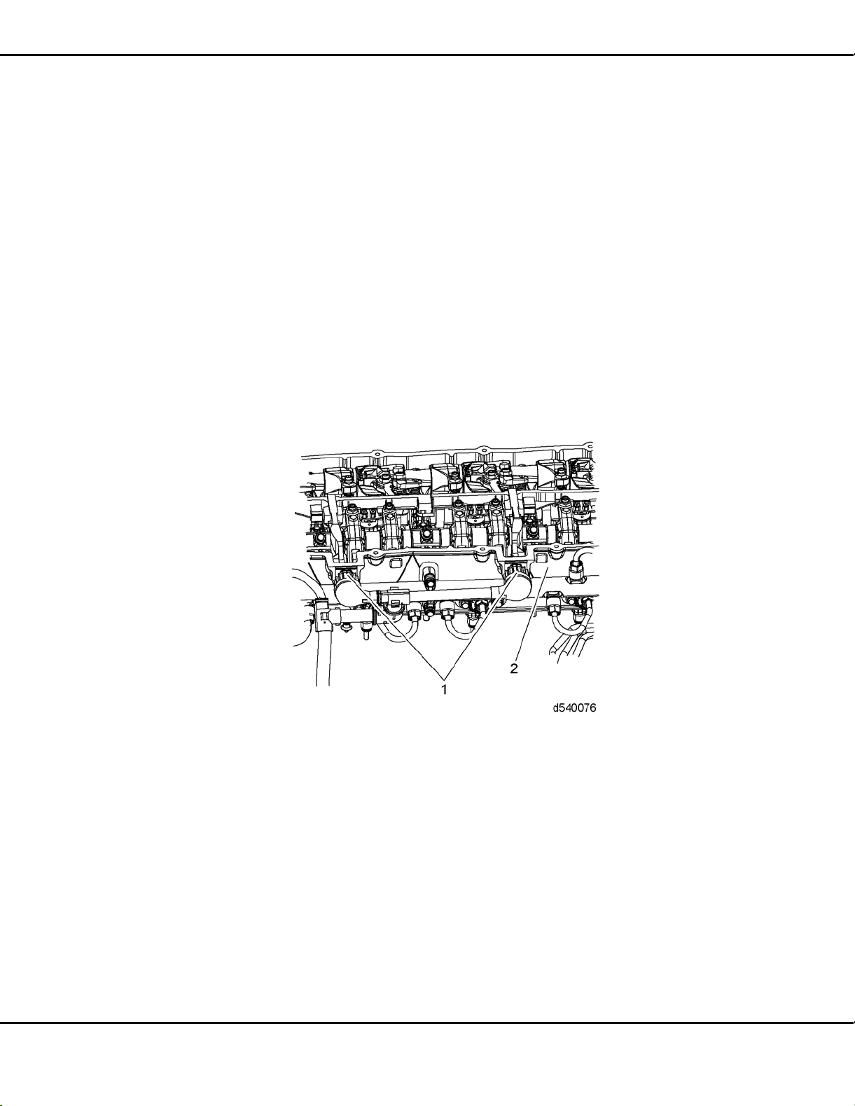
1.1 DESCRIPTION AND OPERATION OF ROCKER COVER AND RELATED
PART S
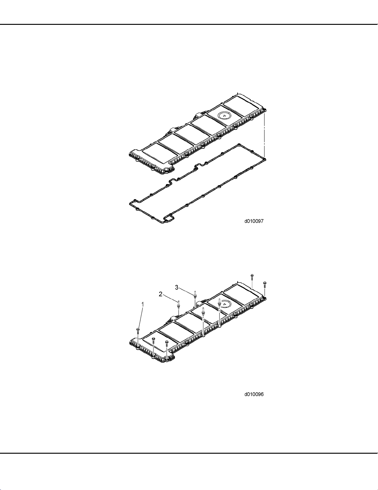
The rocker cover (2) is made of an aluminum or plastic material and uses an elastome
r seal (1)
which completely encloses the valve operating mechanism including the overhead camshafts,
brake assemblies and the injector harness.
1. Gasket 4. Air Cleaner Bracket
2. Rocker Cover 5. Stud (Bolt)
3. Bolt
Figure 1-1 Rocker Cover
All information subject to change without notice.
DDC-SVC-MAN-0081 2010 Copyright © 2010 DETROIT DIESEL CORPORATION 1-3
Page 14
1.2 REMOVAL OF THE ROCKER COVER
1.2 REMOVAL OF THE ROCKER COVER
Remove as follows:
1. Steam clean the engine.
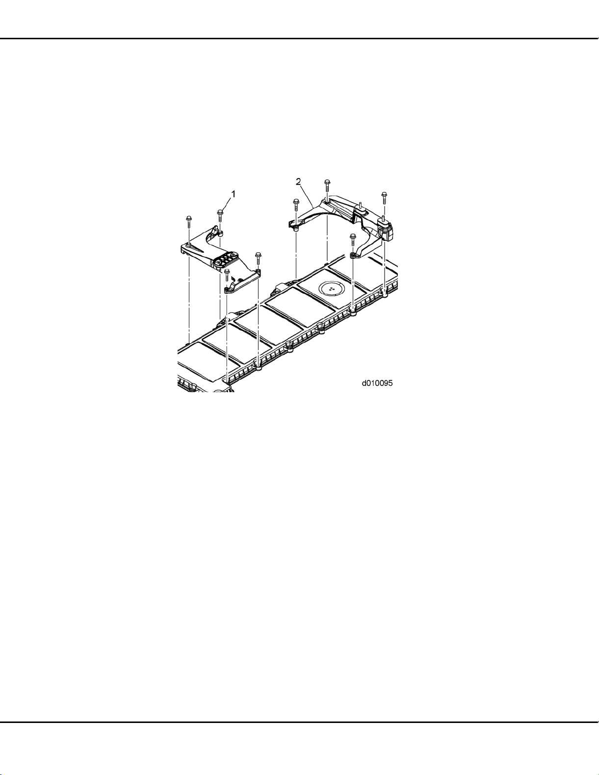
2. Remove bolts (1) or nuts (if equipped) from the two air filter housing brackets (2) and
remove housings from the rocker cover.
1-4 DDC-SVC-MAN-0081 2010 Copyright © 2010 DETROIT DIESEL CORPO RATION
All information subject to change without notice.
Page 15
EPA07/10 DD PLATFORM WORKSHOP MANUAL - ENGINE
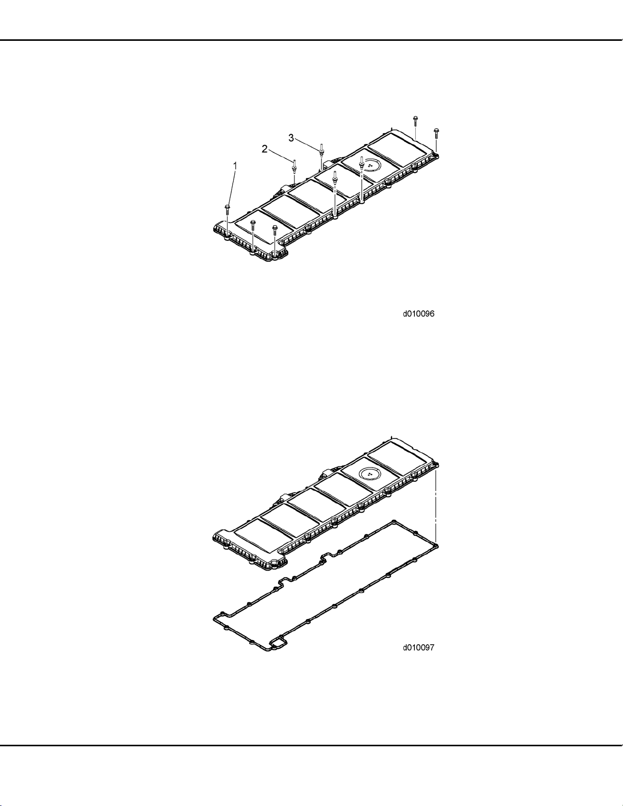
3. Loosen the bolts (1) or stud bolts (2) (if equipped) and isolators (3); remove rocker cover.
NOTE:
Mark the location of the stud bolts. The stud bolts must be replaced in their original
location during installation.
4. Remove rocker cover gasket from the
rocker cover.
All information subject to change without notice.
DDC-SVC-MAN-0081 2010 Copyright © 2010 DETROIT DIESEL CORPORATION 1-5
Page 16
1.3 CLEANING AND INSPECTION OF THE ROCKER COVER
1.3 CLEANING AND INSPECTION OF THE ROCKER COVER
Clean as follows:
1. Clean cover in clean solvent or fuel.
EYE INJURY
To avoid injury from flying debris when using compressed
air, wear adequate eye protection (face shield or safety
goggles) and do not exceed 276 kPa (40 psi) air pressure.
2. Blow dry with compressed air.
3. Check the rocker cover, breather passage and seal for damage. Replace as necessary.
4. Inspect the bolts. Replace if damaged.
1-6 DDC-SVC-MAN-0081 2010 Copyright © 2010 DETROIT DIESEL CORPO RATION
All information subject to change without notice.
Page 17
EPA07/10 DD PLATFORM WORKSHOP MANUAL - ENGINE
1.4 INSTALLATION OF THE ROCKER COVER
Install as follow s:
1. Install rocker cover gasket into groove in rocker cover.
2. Install bolts (1) or stud bolts (2) (if removed) and isolators (3) into rocker cover.
3. Install roc
ker c over onto camshaft housing.
4. Finger tighten all bolts (1) and stud bolts; then torque to 20 N·m (14 lb·ft).
All information subject to change without notice.
DDC-SVC-MAN-0081 2010 Copyright © 2010 DETROIT DIESEL CORPORATION 1-7
Page 18

1.4 INSTALLATION OF THE ROCKER COVER
5. Install the two air filter brackets (2) (if equipped), onto the rocker cover and torque the
eight nuts to 20 N·m (14 lb·ft).
ENGINE EXHAUST
To avoid injury from inhaling engine exhaust, always
operate the engine in a well-venti
exhaust is toxic.
6. Start the engine and check f
lated area. Engine
or leaks.
1-8 DDC-SVC-MAN-0081 2010 Copyright © 2010 DETROIT DIESEL CORPO RATION
All information subject to change without notice.
Page 19

2 CAMSHAFT AND ROCKER SHAFT/ENGINE BRAKE
ASSEMBLY
Section Page
2.1 DESCRIPTION AND OPERATION OF CAMSHAFT AND
SHAFT/ENGINE BRAKE ASSEMBLY AND RELATED PARTS ............... 2-3
2.2 REMOVAL OF CAMSHAFT AND ROCKER SHAFT/ENGINE BRAKE
ASSEMBLY .............................................................................................. 2-7
2.3 INSPECTION OF THE CAMSHAFT AND ROCKER SHAFT/ENGINE
BRAKE ASSEMBLY ................................................................................. 2-15
2.4 INSTALLATION OF THE CAMSHAFT
BRAKE ASSEMBLY ................................................................................. 2-16
2.5 DD13 EGR COOLER CLEANING PROCEDURE TO REMOVE EXCESS
FUEL FROM COOLER AFTER E
2.6 DD15 EGR COOLER CLEANING PROCEDURE TO REMOVE EXCESS
FUEL FROM COOLER AFTER ENGINE BRAKE SOLENOID FAILURE 2-31
ANDROCKERSHAFT/ENGINE
NGINE BRAKE SOLENOID FAILURE
ROCKER
2-26
Page 20

2-2 DDC-SVC-MAN-0081 2010 Copyright © 2010 DETROIT DIESEL CORPO RATION
All information subject to change without notice.
Page 21
EPA07/10 DD PLATFORM WORKSHOP MANUAL - ENGINE
2.1 DESCRIPTION AND OPERATION OF CAMSHAFT AND ROCKER
SHAFT/ENGINE BRAKE ASSEMBLY AND RELATED PARTS
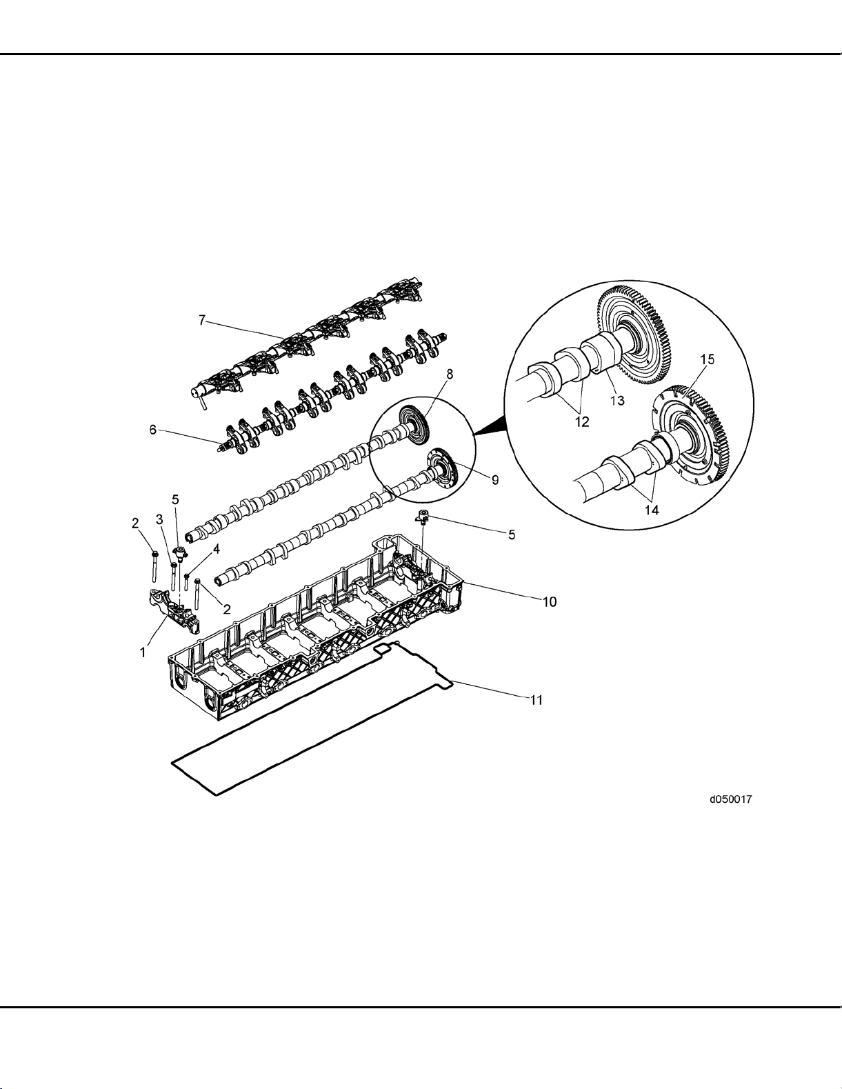
The engine uses a dual overhead camshaft and rocker shaft design. The intake and ex
haust
camshafts are timed to each other, through a geartrain, to the crankshaft. The camshaft housing
houses the camshafts and valve train. It has internal oil passages to supply oil from the block to the
camshaft and rocker bearings along with pressurized oil to the engi
ne brake rockers via the engine
brake solenoids through the exhaust shaft. T he camshaft housing is made of aluminium material.
1. Camshaft Bearing Cap 6. Intake Rocker Arm
2. Bolt 120 mm 7. Exhaust Rocker Arm
3. Bolt 108 mm 8. Exhaust Camshaft and Gear
4. Bolt 63 mm 9. Intake Camshaft and Gear
5. Engine Brake Solenoid
10. Camshaft Housing 15. Intake Camshaft Tone Wheel
11. Gasket
12. Exhaust Camshaft Lobes
13. Exhaust Camshaft Brake Cam
Lobe
14. Intake Camshaft Lobes
Figure 2-1 Camshaft Housing and Related Parts
All information subject to change without notice.
DDC-SVC-MAN-0081 2010 Copyright © 2010 DETROIT DIESEL CORPORATION 2-3
Page 22

2.1 DESCRIPTION AND OPERATION OF CAMSHAFT AND ROCKER SHAFT/ENGINE BRAKE ASSEMBLY
AND RELATED PARTS
2.1.1 Engine Braking
The engine uses an integral engine brake. Engine braking is controlled electronica
llybythe
engine control system with an electric solenoid. When activated, the solenoid allows oil pressure
to activate a piston on the exhaust rocker arm. Engine braking is accomplished with a single
exhaust valve in each cylinder. The exhaust camshaft uses a separate
engine brake-only lobe that
allows for double valve activation for high efficiency braking. The exhaust valve is first operated
toward the completion of the intake stroke, closed during the compression stroke and opened a
second time when the compression stroke is completed. The engine
brake system is enabled using
the following components:
For EPA07 engines:
□ Engine brake solenoid valve in front of engine applies l
ow engine braking.
□ Engine brake solenoid valve in rear of engine applies medium engine braking.
□ For high, both front and rear solenoids are activated.
□ Six exhaust rocker arms with actuator pistons.
□ Six brake rocker arms which are actuated by the brake cam lobes.
□ Exhaust camshaft has one brake cam lobe per cylinder.
2-4 DDC-SVC-MAN-0081 2010 Copyright © 2010 DETROIT DIESEL CORPO RATION
All information subject to change without notice.
Page 23
EPA07/10 DD PLATFORM WORKSHOP MANUAL - ENGINE
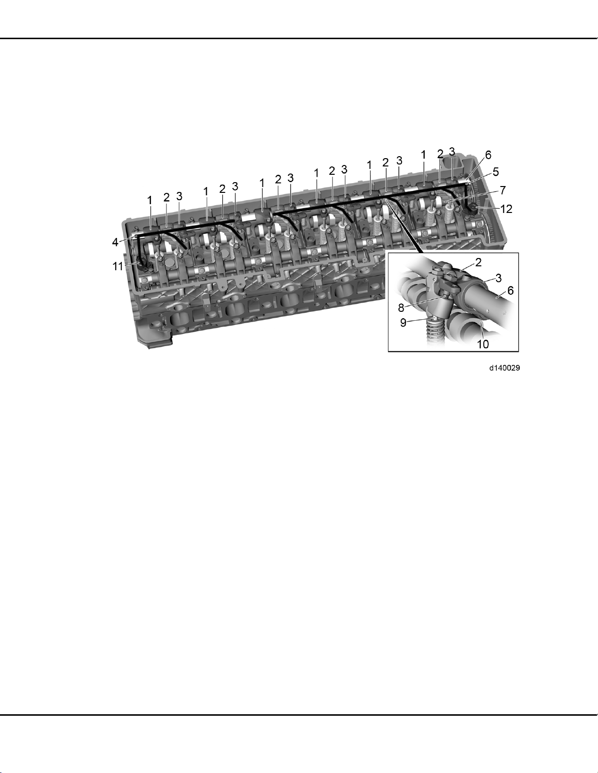
For EPA07 engines, the exhaust rocker arm shaft lubricating oil passages direct pressurized oil to
the rocker arms. The exhaust rocker arm has two additional oil passages to operate t
he engine
brakes. Oil for cylinders 1 and 2 is supplied by the Front Engine Brake Solenoid Valve. Oil for
cylinders3to6aresuppliedbytheRear Engine Brake Solenoid Valve.
1. Exhaust Rocker Arm 7. Exhaust Camshaft
2. Exhaust Rocker Arm with Actuator Piston 8. Actuator Piston
3. Brake Rocker Arm 9. Exhaust Valve
4. Oil Passage for Cylinders 1 and 2
5. Oil Passage for Cylinders 3, 4, 5 and 6
6. Exhaust Rocker Arm Sh aft
10. Brake Cam Lobe
11. Engine Brake Solenoid Valve, Front
12. Engine Brake Solenoid Valve, Rear
Figure 2-2 EPA07 Engine Brake
For EPA10 engines:
□ Engine brake solenoid valve in front of engine applies low engine braking.
□ For medium engine braking, both front and rear solenoids are activated.
□ For high, both front and rear solenoids are activated, along with EGR.
□ Six exhaust rocker arms with actuator pistons.
□ Six brake rocker arms which are actuated by the brake cam lobes.
□ Exhaust camshaft has one brake cam lobe per cylinder.
All information subject to change without notice.
DDC-SVC-MAN-0081 2010 Copyright © 2010 DETROIT DIESEL CORPORATION 2-5
Page 24

2.1 DESCRIPTION AND OPERATION OF CAMSHAFT AND ROCKER SHAFT/ENGINE BRAKE ASSEMBLY
AND RELATED PARTS
For EPA10 engines, the exhaust rocker arm shaft lubricating oil passages direct pressurized oil to
the rocker arms. The exhaust rocker arm has two additional oil passages to operate t
he engine
brakes. Oil for cylinders 1 through 3 is supplied by the Front Engine Brake Solenoid Valve. Oil
for cylinders 4 through 6 are supplied by the Rear Engine Brake Solenoid Valve.
1. Exhaust Rocker Arm 7. Exhaust Camshaft
2. Exhaust Rocker Arm with Actuator Piston 8. Actuator Piston
3. Brake Rocker Arm 9. Exhaust Valve
4. Oil Passage for Cylinders 1, 2 and 3
5. Oil Passage for Cylinders 4, 5 and 6
6. Exhaust Rocker Arm Shaft
10. Brake Cam Lobe
11. Engine Brake Solenoid Val
12. Engine Brake Solenoid Valve, Rear
Figure 2-3 EPA 10 Engine Brake
ve, Front
2-6 DDC-SVC-MAN-0081 2010 Copyright © 2010 DETROIT DIESEL CORPO RATION
All information subject to change without notice.
Page 25
EPA07/10 DD PLATFORM WORKSHOP MANUAL - ENGINE
2.2 REMOVAL OF CAMSHAFT AND ROCKER SHAFT/ENGINE BRAKE
ASSEMBLY
Remove as follows:
1. Turn engine OFF, (key OFF, engine OFF).
2. Steam clean the engine.
3. Disconnect the battery power to the engine. Refer to OEM procedure
s.
4. Remove the air cleaner and the turbocharger inlet pipe and hose. Refer to OEM procedures.
5. Remove air cleaner housing. Refer to OEM procedures.
6. Remove the rocker cover. Refer to section 1.2.
7. Remove the two 14-pin fuel injector harness connectors (1) from the camshaft housing
housing (2).
NOTE:
Top Dead Center (TDC) can be confirmed by installing camshaft timing tool. For
the DD13 use Camshaft Timing Tool (W470589034000). For the EPA07 DD15 use
Camshaft Timing Tool
(W470589054000). For the EPA10 DD15 use Camshaft Timing
Tool (W470589104000).
8. Using Engine Barring tool (J-46392), rotate the crankshaft to TDC on cylinder No. 1.
All information subject to change without notice.
DDC-SVC-MAN-0081 2010 Copyright © 2010 DETROIT DIESEL CORPORATION 2-7
Page 26
2.2 REMOVAL OF CAMSHAFT AND ROCKER SHAFT/ENGINE BRAKE ASSEMBLY
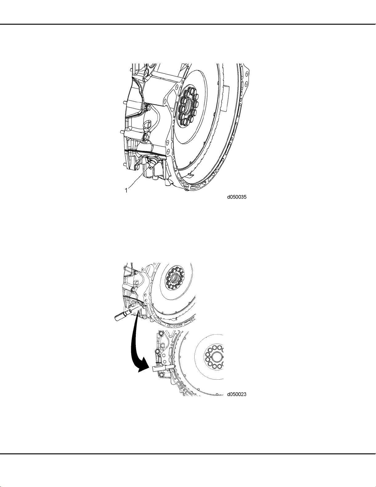
9. Remove the Crankshaft Position Sensor (CKP) (1) from t he rear of the flywheel housing.
Refertosection.
10. To accurately locate TDC, install the flywheel housing crankshaft TDC Locating Pin
(W470589001500) into the CKP sensor hole located in the rear of the flywheel housing.
The plastic tip will protrude int
o the cutout in the tone wheel. TDC can be verified by the
proper installation of the camshaft timing tool.
2-8 DDC-SVC-MAN-0081 2010 Copyright © 2010 DETROIT DIESEL CORPO RATION
All information subject to change without notice.
Page 27
EPA07/10 DD PLATFORM WORKSHOP MANUAL - ENGINE
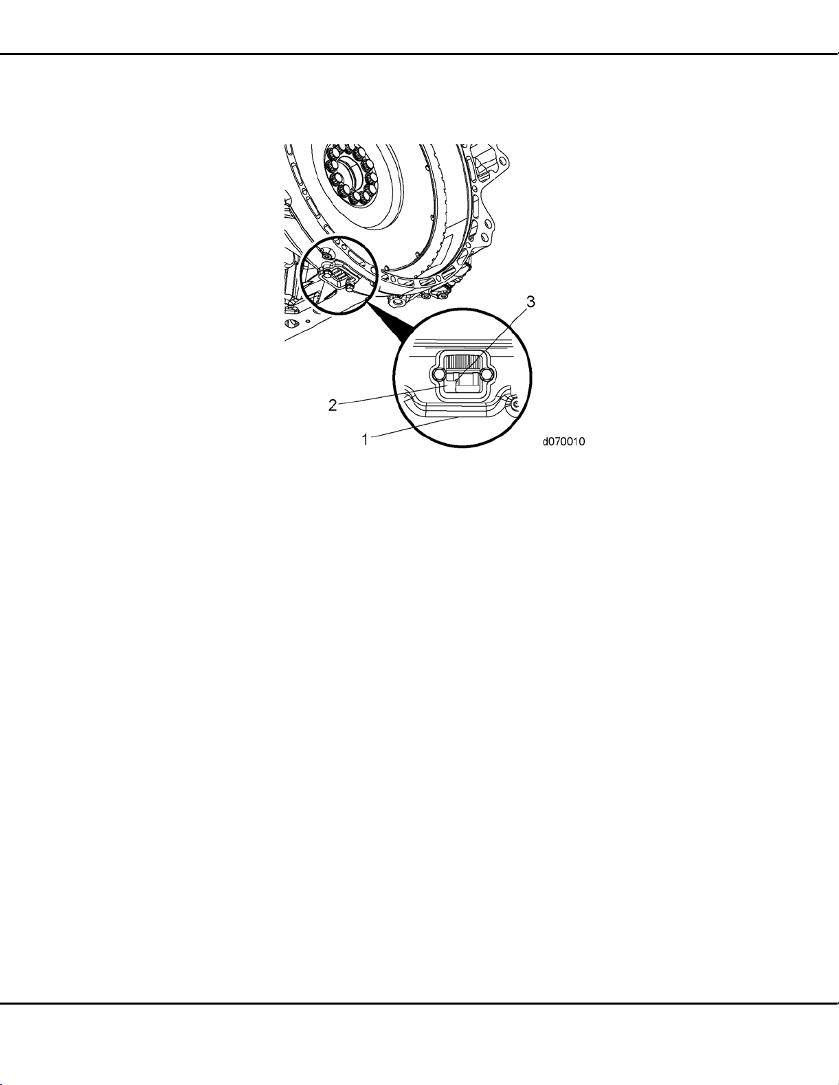
11. When the TDC dot (3) between two teeth on the flywheel aligns with the edge of pointer
(2), the engine is at TDC firing stroke.
12. For EPA07 DD13:
[a] Disconnect both 14-pin injector harness connectors (8).
[b] Disconnect the 24 electrical te
rminals at the fuel injectors (7).
[c] Disconnect two wiring terminals at each engine brake solenoid (6).
All information subject to change without notice.
DDC-SVC-MAN-0081 2010 Copyright © 2010 DETROIT DIESEL CORPORATION 2-9
Page 28

2.2 REMOVAL OF CAMSHAFT AND ROCKER SHAFT/ENGINE BRAKE ASSEMBLY
[d] Loosen the Allen screws holding the intermediate frame (5) to the camshaft housing
(1). Remove the intermediate frame .
13. For EPA10 engines:
[a] Remove the fuel injector electrical harness clips (2) from the 14-pin electrical
connectors.
2-10 DDC-SVC-MAN-0081 2010 Copyright © 2010 DETROIT DIESEL CORPORATION
All information subject to change without notice.
Page 29

EPA07/10 DD PLATFORM WORKSHOP MANUAL - ENGINE
[b] Remove the bolts securing the two-piece fuel injector electrical harness (1 and 3) and
remove the harness from the camshaft housing housing.
14. Remove the engine brake solenoids from the camshaft housing.
NOTICE:
Ensure when loosening the rocker shaft bolts that the bolts are
loosened fro m the inside bolts outward in 1/2 turn increments.
The increment procedure need
stobefollowedtopreventthe
rocker shaft from breaking.
15. Completely loosen all
of the adjusting screws on all of the rocker arms.
16. Loosen the seven bolts securing the intake rocker shaft to the camshaft bearing caps.
NOTICE:
Make sure that the camshaft housing housing is not damaged
during removal of the intake/exhaust rocker shaft assemblies.
All information subject to change without notice.
DDC-SVC-MAN-0081 2010 Copyright © 2010 DETROIT DIESEL CORPORATION 2-11
Page 30
2.2 REMOVAL OF CAMSHAFT AND ROCKER SHAFT/ENGINE BRAKE ASSEMBLY
17. Using Rocker Arm Lifter / Spacer tool (W470589044000) for the DD13, or Rocker Arm
Lifter / Spacer Intake tool (W470589004000) for the DD15, remove the intake rocker
shaft assembly.
NOTICE:
Ensure when loosening the rocker shaft bolts that the bolts are
loosened from the inside bolts outward in 1/2 turn increments.
The increment procedure needs to be followed to prevent the
rocker shaft from breaking.
18. Loosen the seven bolts securing the exhaust rocker
shaft to the camshaft caps.
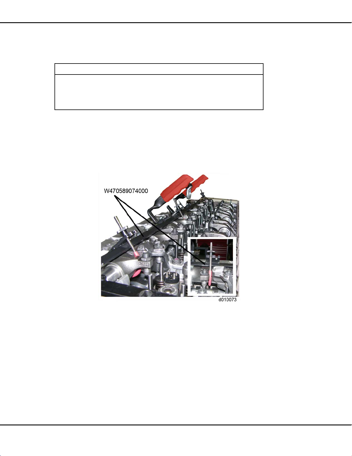
19. Using Rocker Arm Lifter / Spacer Exhaust (W470589074000) for the DD13 or Rocker
Arm Lifter / Spacer Exhaust (W470589004000) for the DD15, remove the exhaust rocker
shaft assembly. When removing the EPA10 exhau
st rocker shaft, ensure the rockers are
in the up position.
NOTE:
The engine brake s
olenoids do not have to be removed unless damaged.
NOTE:
Mark cap position for proper reassembly.
2-12 DDC-SVC-MAN-0081 2010 Copyright © 2010 DETROIT DIESEL CORPORATION
All information subject to change without notice.
Page 31

EPA07/10 DD PLATFORM WORKSHOP MANUAL - ENGINE
20. Remove the remaining bolts (1) from t he camshaft bearing caps (2).
21. Using tool Cam Bearing Cap Puller (J-488
83) and Injector Unit Pump Puller (J-46375),
remove the camshaft bearing caps (1) from the camshaft housing.
All information subject to change without notice.
DDC-SVC-MAN-0081 2010 Copyright © 2010 DETROIT DIESEL CORPORATION 2-13
Page 32

2.2 REMOVAL OF CAMSHAFT AND ROCKER SHAFT/ENGINE BRAKE ASSEMBLY
22. Remove the intake and exhaust camshaft assemblies (1 & 2) from the camshaft housing
(3). Use care not to damage intake cam tone wheel when handling.
2-14 DDC-SVC-MAN-0081 2010 Copyright © 2010 DETROIT DIESEL CORPORATION
All information subject to change without notice.
Page 33

EPA07/10 DD PLATFORM WORKSHOP MANUAL - ENGINE
2.3 INSPECTION OF THE CAMSHAFT AND ROCKER SHAFT/ENGINE
BRAKE ASSEMBLY
Inspect the camshaft and rocker shaft assemblies as follows:
1. Inspect the camshafts for lobe damage; replace if necessary.
2. Inspect the camshaft gears for damage; replace if necessary.
3. Inspect the rocker shaft for scoring or scuffing; replace if necess
ary.
4. Inspect rocker arms for roller and bushing damage; replace if necessary.
5. Inspect adjusting screws and buttons; replace if necessary.
6. Inspect cam caps and cam journals in camshaft housing
for damage; replace if necessary.
7. Inspect the tone wheel on the intake camshaft for cracks, bending or any damage. If
damage is found, replace the intake camshaft.
All information subject to change without notice.
DDC-SVC-MAN-0081 2010 Copyright © 2010 DETROIT DIESEL CORPORATION 2-15
Page 34

2.4 INSTALLATION OF THE CAMSHAFT AND ROCKER SHAFT/ENGINE BRAKE ASSEMBLY
2.4 INSTALLATION OF THE CAMSHAFT AND ROCKER SHAFT/ENGINE
BRAKE ASSEMBLY
Install as follows:
1. Verify that the crankshaft is at top dead center (TDC) on cylinder number one using
TDC Locating Pin (W470589001500) installed in crankshaft position sensor (CKP) hole
located in the flywheel housing.
2. Install Camshaft Timing Tool (W470589054000) (1) for EPA07 DD15, (W470589104000)
for EPA10 DD15, and (W470589034000) for EPA10 DD13 to the rear of the camshaft
housing. Tighten the two bo
lts.
2-16 DDC-SVC-MAN-0081 2010 Copyright © 2010 DETROIT DIESEL CORPORATION
All information subject to change without notice.
Page 35

EPA07/10 DD PLATFORM WORKSHOP MANUAL - ENGINE
3. Locate the etched triangle on the camshaft gear teeth and mark the teeth with a paint pen.
4. Lubricate the lower camshaft bearing surfaces and camshaft journals before inst
camshafts. Install the exhaust and intake camshaft gear assemblies into the camshaft
housing.
5. Align the marked gear teeth with the marks on the timing tool.
alling the
6. Install Camshaft Timing Tool (W470589054000) (1) for EPA07 DD15, (W470589104000)
for EPA10 DD15, and (W470589034000) for EPA10 DD13 to the front of the camshaft
housing and into the groove
s cut into the camshafts. Secure timing tool to the camshaft
with a bolt.
[a] At this point the front timing tool should slide into the camshaft grooves easily with
no drag.
All information subject to change without notice.
DDC-SVC-MAN-0081 2010 Copyright © 2010 DETROIT DIESEL CORPORATION 2-17
Page 36

2.4 INSTALLATION OF THE CAMSHAFT AND ROCKER SHAFT/ENGINE BRAKE ASSEMBLY
[b] If there is excessive drag when installing the tool, the camshafts are out of time. If so,
repeat this procedure at Step 3.
7. Verify that the marks on the gear teeth match the marks on the timing tool.
NOTICE
The camshaft caps are numbered and need to be installed
correctly.
8. Install the seven camshaft caps onto intake and exhaust camshafts.
9. The first and seventh camshaft caps hold the engine brake solenoid to camshaft cap.
Replace the O-rings o
n the solenoid prior to reinstallation. Install the engine brake
solenoid.
NOTE:
There are 30 bolts r
etaining the DD13 camshaft assemblies (shown); 14 120 mm (M10)
bolts, seven 108 mm (M10) bolts and nine 63 mm (M8) bolts. The DD15 uses 28 bolts,
with two external bolts at the rear of the camshaft housing.
2-18 DDC-SVC-MAN-0081 2010 Copyright © 2010 DETROIT DIESEL CORPORATION
All information subject to change without notice.
Page 37

EPA07/10 DD PLATFORM WORKSHOP MANUAL - ENGINE
10. Install the 30 bolts to camshaft caps; finger tighten the bolts. Refer to figure for proper
bolt placement.
11. Using the torque sequence shown below torque the M10 camshaft cap bolts to the
following:
□ 20 N·m (15 lb·ft)
□ Then torque to 50-55 N·m (37-40 lb·ft).
All information subject to change without notice.
DDC-SVC-MAN-0081 2010 Copyright © 2010 DETROIT DIESEL CORPORATION 2-19
Page 38

2.4 INSTALLATION OF THE CAMSHAFT AND ROCKER SHAFT/ENGINE BRAKE ASSEMBLY
12. Using the torque sequence shown below, torque the nine 63 mm M8 bolts to 30 N·m
(22 lb·ft).
13. Remove TDC Locating Pin (W470589001500) from CKP sensor hole in the flywheel
housing.
14. Install crankshaft position se
nsor. Refer to section .
15. Install a dial indicator onto gear case and zero out the dial indicator.
16. Position the stem of dial indicator to rest between the teeth on the camshaft gear.
17. Hold the number five idler
gear with a screwdriver. Check the lash between the camshaft
gear and idler gear number five.
2-20 DDC-SVC-MAN-0081 2010 Copyright © 2010 DETROIT DIESEL CORPORATION
All information subject to change without notice.
Page 39

EPA07/10 DD PLATFORM WORKSHOP MANUAL - ENGINE
18. The dial indicator should read 0.051 - 0.257 mm (0.002 - 0.010 in). If the gear lash is
excessive between either camshaft gear and the number five idler gear, inspect the n
umber
five idler gear spindle, camshaft gear and camshaft housing. Repair as necessary.
NOTICE:
The camshaft journal area is lubrica ted by oil that has to travel
throughthe rockershaft. Iftherocker shaftis installed incorrectly,
oil passages do not lineup. This results in insufficient lubrica
tion
and damage to the camshaft journals. Incorrect shaft installation
may also result in the engine brakes not functioning and cause
damage to the rocker arm bushings.
All information subject to change without notice.
DDC-SVC-MAN-0081 2010 Copyright © 2010 DETROIT DIESEL CORPORATION 2-21
Page 40

2.4 INSTALLATION OF THE CAMSHAFT AND ROCKER SHAFT/ENGINE BRAKE ASSEMBLY
NOTICE:
The markings on the front of the rockers shafts must face the
front of the engine for proper rocker arm lubrication and engine
brake operation.
NOTICE:
Ensure when tightening the rocker shaft bolts t hat the bolts are
drawn down from the inside bolts outward in 1/2 turn increments,
before final torque. If the rocker shaft bolt isfully torqued without
using the increment procedure the rocker shaft can br
eak.
NOTE:
On EPA10 engines the intake and exhaust rocker shaf
ts are marked "TOP FRONT" and
“TOP REAR.” Top front must face towards the front of the engine.
19. Remove timing tools.
2-22 DDC-SVC-MAN-0081 2010 Copyright © 2010 DETROIT DIESEL CORPORATION
All information subject to change without notice.
Page 41

EPA07/10 DD PLATFORM WORKSHOP MANUAL - ENGINE
20. Using Rocker Arm Lifter / Spacer Intake (W470589044000) (1) for the DD13 or Rocker
Arm Lifter / Spacer Intake (W470589004000) for the DD15, install the intake rocker
shaft
assembly to the camshaft cap and secure with seven clamping blocks and bolts.
21. Using the torque sequence shown below, torque the bolts to 50-55 N·m (36-41 lb·ft) +90°.
All information subject to change without notice.
DDC-SVC-MAN-0081 2010 Copyright © 2010 DETROIT DIESEL CORPORATION 2-23
Page 42

2.4 INSTALLATION OF THE CAMSHAFT AND ROCKER SHAFT/ENGINE BRAKE ASSEMBLY
22. Using Rocker Arm Lifter / Spacer (W4705589074000) for the DD13 or Rocker Arm Lifter
/ Spacer Intake (W470589004000) for the DD15, install the exhaust rocker shaft ass
embly
to the camshaft cap and secure with seven clamping blocks and bolts.
23. Using the torque sequence shown below, torque the bolts to 50-55 N·m (36-41 lb·ft) +90°.
24. Remove timing tools.
25. Install the fuel injectors, if removed. Refer to section .
26. Lash the valves and engine brakes. Refer to section 14.15.
27. Install the fuel injector wiring harness. Refer to section .
28. Install the rocker cover. Refer to section 1.4.
29. Reconnect the battery power to the engine. Refer to OEM procedures.
2-24 DDC-SVC-MAN-0081 2010 Copyright © 2010 DETROIT DIESEL CORPORATION
All information subject to change without notice.
Page 43

EPA07/10 DD PLATFORM WORKSHOP MANUAL - ENGINE
30. Install air cleaner housing. Refer to OEM procedures.
31. Install the turbocharger inlet pipe and hose, and air cleaner. Refer to OEM proced
32. Prime lubrication system. Refer to section 27.1.
ures.
All information subject to change without notice.
DDC-SVC-MAN-0081 2010 Copyright © 2010 DETROIT DIESEL CORPORATION 2-25
Page 44

2.5 DD13 EGR COOLER CLEANING PROCEDURE TO REMOVE EXCESS FUEL FROM COOLER AFTER
ENGINE BRAKE SOLENOID FAILURE
2.5 DD13 EGR COOLER CLEANING PROCEDURE TO REMOVE EXCESS
FUEL FROM COOLER AFTER ENGINE BRAKE SOLENOID FAILURE
Inspect as follows:
1. Clamp
2. Hose
3. Coolant C rossover Pipe
4. Bolt
5. Support
6. Coolant Connecting Tube
7. Exhaust Gas Connecting Tube
8. Gasket
9. Seal Ring
10. Banjo Union 19. Exhaust Gas Crossover Tube
11. Banjo Bolt 20. Gasket
12. Bolt 21. Bolt
13. Bolt 22. Venturi
14. Outlet Nipple 23. Mixer Pipe
15. Seal 24. Seal Ring
16. Exhaust Gas Recirculation
Cooler Water Manifold Assembly
17. Clamps 26. Lifting Bracket Mounting Bolt
18. H ot Pipe 27. Front Lifting Bracket
25. Bolt
Figure 2-4 EPA10 DD13 EGR Cooler Water Manifold and Related Parts
2-26 DDC-SVC-MAN-0081 2010 Copyright © 2010 DETROIT DIESEL CORPORATION
All information subject to change without notice.
Page 45

EPA07/10 DD PLATFORM WORKSHOP MANUAL - ENGINE
1. Clamp
10. Banjo Union 19. Exhaust Gas Crossover Tube /
Lifting Eye
2. Hose
3. Coolant Crossover Pipe
4. Bolt
5. Support
6. Coolant Connecting Tube
7. Exhaust Gas Connecting Tube
11. Banjo Bolt 20. Gasket
12. Bolt 21. Bolt
13. Bolt 22. Venturi
14. Outlet Nipple 23. Mixer Pipe
15. Seal 24. Seal Ring
16. Exhaust Gas Recirculation
25. Bolt
Cooler Water Manifold Assembly
8. Gasket
9. Seal Ring
17. Clamps 26. Bolt
18. Hot Pipe
Figure 2-5 EPA10 DD13 EGR Cooler Water Manifold and Related Parts
All information subject to change without notice.
DDC-SVC-MAN-0081 2010 Copyright © 2010 DETROIT DIESEL CORPORATION 2-27
Page 46

2.5 DD13 EGR COOLER CLEANING PROCEDURE TO REMOVE EXCESS FUEL FROM COOLER AFTER
ENGINE BRAKE SOLENOID FAILURE
Check as follows:
NOTICE:
This procedure must be followed after replacing an engine
brake solenoid due to any failure that could cause high DOC
temperature codes, excessive fuel, oil, or coolant to enter the
exhaust system. Failure to perform this procedure could cause
severe engine damage.
1. Remove the marmon clamps (2) and EGR hot pipe (3) and inspect for any signs of liquid
or moisture. The EGR hot pipe (exhaust pipe) and EGR
cooler inlet (1) should have
a black dry soot residue inside.
[a] If liquid or moisture is present in the pipe, go to the next step.
[b] If there is no sign of liquid or moisture in the p
hot pipe. No further action is required.
ipe or EGR cooler (1), install the
2-28 DDC-SVC-MAN-0081 2010 Copyright © 2010 DETROIT DIESEL CORPORATION
All information subject to change without notice.
Page 47

EPA07/10 DD PLATFORM WORKSHOP MANUAL - ENGINE
2. Remove the mixer pipe (1) from the cold boost pipe (2).
3. Remove the exhaust gas crossover tube /
lifting eye (2) and venturi (6).
4. Place a towel over the outlet of the EGR cooler and retain it with a zip tie.
All information subject to change without notice.
DDC-SVC-MAN-0081 2010 Copyright © 2010 DETROIT DIESEL CORPORATION 2-29
Page 48

2.5 DD13 EGR COOLER CLEANING PROCEDURE TO REMOVE EXCESS FUEL FROM COOLER AFTER
ENGINE BRAKE SOLENOID FAILURE
To avoid injury from flying debris when using compressed
air, wear adequate eye protection (face shield or safety
goggles) and do not exceed 40 psi (276 kPa) air pressure.
5. Using a rubber tipped blow gun, blow compressed shop air into th
e individual tubes in
the EGR cooler to clear any excess fuel, soot, and carbon.
6. After performing the cleaning procedure, refer to section to install the:
[a] mixer pipe.
[b] exhaust gas crossover tube/lifting eye (EPA07 engines) and exhaust gas crossover
tube (EPA10 engines).
[c] venturi.
7. If the cooler has an excessive amount of buildup that cannot be removed, replace the
EGR cooler. R efer to section .
2-30 DDC-SVC-MAN-0081 2010 Copyright © 2010 DETROIT DIESEL CORPORATION
All information subject to change without notice.
Page 49

EPA07/10 DD PLATFORM WORKSHOP MANUAL - ENGINE
2.6 DD15 EGR COOLER CLEANING PROCEDURE TO REMOVE EXCESS
FUEL FROM COOLER AFTER ENGINE BRAKE SOLENOID FAILURE
Inspect as follows:
1. Venturi 9. Connecting Tube
2. Bolt
3. Gasket
4. Bolt
5. Exhaust Gas Crossover Tube
6. Bolt
7. Lifting Bracket
8. Connecting Tube
10.Seal Ring 18. Hot Pipe
11. Banjo Union 19. Water Manifold
12. Banjo Bolt 20. Support
13. Exhaust Gas Cooler 21. Clamp
14. Strap 22. Hose
15. Shim 23. Mixer Pipe
16. Clamp 24. Coolant Del
17. Metal Seal
ivery Pipe
25. Seal Ring
Figure 2-6 EPA10 DD15 EGR Cooler and Related Parts
All information subject to change without notice.
DDC-SVC-MAN-0081 2010 Copyright © 2010 DETROIT DIESEL CORPORATION 2-31
Page 50

2.6 DD15 EGR COOLER CLEANING PROCEDURE TO REMOVE EXCESS FUEL FROM COOLER AFTER
ENGINE BRAKE SOLENOID FAILURE
1. Venturi 9. Banjo Union
2. Bolt
3. Gasket
4. Bolt
5. Exhaust Gas CrossoverTube/Lifting
Eye
6. Connecting Tube
7. Connecting Tube
8. Seal Ring
10. Banjo Bolt 18. Support
11. Exhaust Gas Cooler 19. Clamp
12. Strap 20. Hose
13. Shim 21. Mixer Pipe
14. Clamp 22. Coolant Delivery Pipe
15. Metal Seal 23. Seal Ring
16. Hot Pipe
17. Water Manifold
Figure 2-7 EPA07 DD15 EGR Cooler and Re lated Parts
2-32 DDC-SVC-MAN-0081 2010 Copyright © 2010 DETROIT DIESEL CORPORATION
All information subject to change without notice.
Page 51

EPA07/10 DD PLATFORM WORKSHOP MANUAL - ENGINE
Check as follows:
NOTICE:
This procedure must be followed after replacing an engine
brake solenoid due to any failure that could cause high DOC
temperature codes, excessive fuel, oil, or coolant to enter the
exhaust system. Failure to perform this procedure could cause
severe engine damage.
1. Remove the clamps (2), exhaust pipe (4) and gaskets (3) from the EGR cooler (1) and
inspect and inspect for any signs of liquid or moist
ure. The EGR hot pipe and EGR cooler
inlet should have a black dry soot residue inside.
[a] If liquid or moisture is present in the pipe, go to the next step.
[b] If there is no sign of liquid or moisture in the p
No further action is required. Refer to section .
ipe, install the EGR cooler hot pipe.
All information subject to change without notice.
DDC-SVC-MAN-0081 2010 Copyright © 2010 DETROIT DIESEL CORPORATION 2-33
Page 52

2.6 DD15 EGR COOLER CLEANING PROCEDURE TO REMOVE EXCESS FUEL FROM COOLER AFTER
ENGINE BRAKE SOLENOID FAILURE
2. Remove the mixer pipe (4) from the cold boost pipe (1). Refer to section .
3. Remove the exhaust gas crossover tube/
lifting eye (2) and venturi (3).
4. Place a towel over the outlet of the EGR cooler and retain it with a zip tie.
To avoid injury from flying debr
is when using compressed
air, wear adequate eye protection (face shield or safety
goggles) and do not exceed 40 psi (276 kPa) air pressure.
5. Using a rubber tipped blow gun blow compressed shop air into the individual tubes in
the EGR cooler to clear any excess fuel, soot, and carbon.
6. After performing t
he cleaning procedure, refer to section to install the:
[a] mixer pipe.
[b] exhaust gas crossover tube/lifting eye (EPA07 engines) and exhaust gas crossover
tube (EPA10 eng
ines).
[c] venturi.
7. If the cooler has an excessive amount of buildup that cannot be removed, replace the
EGR cooler
. Refer to section .
2-34 DDC-SVC-MAN-0081 2010 Copyright © 2010 DETROIT DIESEL CORPORATION
All information subject to change without notice.
Page 53

3 CAMSHAFT HOUSING
Section Page
3.1 REMOVAL OF THE CAMSHAFT HOUSING ........................................... 3-3
3.2 INSPECTION OF CAMSHAFT HOUSING ............................................... 3-8
3.3 INSTALLATION OF THE CAMSHAFT HOUSING ................................... 3-9
Page 54

3-2 DDC-SVC-MAN-0081 2010 Copyright © 2010 DETROIT DIESEL CORPO RATION
All information subject to change without notice.
Page 55

EPA07/10 DD PLATFORM WORKSHOP MANUAL - ENGINE
3.1 REMOVAL OF THE CAMSHAFT HOUSING
The camshaft housing houses the camshafts and valve train. It has internal oil passa
ges to supply
oil from the block to the camshaft and rocker bearings along with pressurized oil to the engine
brake rockers via the engine brake solenoids through the exhaust shaft. The camshaft housing is
made of aluminium material.
Remove as follows:
1. Steam clean the engine.
2. Remove the rocker cover. Refer to section 1.2.
3. Disconnect the fuel injector harness (1) from the camshaft housing (2).
4. Remove the following high pressure fuel line components:
PERSONAL INJURY
To prevent the escape of high pressure fuel t hat can
penetrate skin, ensure the engine has been shut down for
a minimum of 10 minu
tes before servicing any component
within the high pressure circuit. Residual high fuel
pressure may be present within the circuit.
[a] High pressure fuel line bracket (1) and high pressure fuel lines from the fuel rail to
the h igh pressure fuel pump (2). Refer to section .
[b] High pressu
All information subject to change without notice.
DDC-SVC-MAN-0081 2010 Copyright © 2010 DETROIT DIESEL CORPORATION 3-3
re fuel lines from the fuel rail to the fuel injectors (3). Refer to section .
Page 56

3.1 REMOVAL OF THE CAMSHAFT HOUSING
[c] Pressure Limiting Valve (PLV) return line from the fuel rail to the fuel filter module
(4). Refer to section .
5. Remove the rocker shaft/engine brake and camshaft assemblies. Refer to section 2.2.
6. Disconnect the intake manifold temperature sensor (2).
3-4 DDC-SVC-MAN-0081 2010 Copyright © 2010 DETROIT DIESEL CORPO RATION
All information subject to change without notice.
Page 57

EPA07/10 DD PLATFORM WORKSHOP MANUAL - ENGINE
7. Disconnect the fuel rail pressure sensor (1).
8. Disconnect the camshaft position sens
or (1) from the camshaft housing (2).
9. Unclip all of the electrical wiring harness attaching points from the camshaft housing.
All information subject to change without notice.
DDC-SVC-MAN-0081 2010 Copyright © 2010 DETROIT DIESEL CORPORATION 3-5
Page 58

3.1 REMOVAL OF THE CAMSHAFT HOUSING
10. Remove the bolt (2) securing the doser coolant line (1) and the P-clip to the camshaft
housing (3).
11. Remove the remaining two bolts (29 and 30) securing the camshaft housing t o the cylinder
head.
12. Attach a lift
ing device to the camshaft housing and lift the camshaft housing off of the
cylinder head.
3-6 DDC-SVC-MAN-0081 2010 Copyright © 2010 DETROIT DIESEL CORPO RATION
All information subject to change without notice.
Page 59

EPA07/10 DD PLATFORM WORKSHOP MANUAL - ENGINE
PERSONAL INJURY
To avoid injury when removing or installing a heavy engine
component, ensure the component is properly supported
and securely attached to an adequate lifting device to
prevent the component from falling.
All information subject to change without notice.
DDC-SVC-MAN-0081 2010 Copyright © 2010 DETROIT DIESEL CORPORATION 3-7
Page 60

3.2 INSPECTION OF CAMSHAFT HOUSING
3.2 INSPECTION OF CAMSHAFT HOUSING
Inspect the camshaft housing as follows:
1. Inspect the camshaft journals for scoring or scratches, replace if damaged.
2. Inspect the camshaft caps for cracks, replace if damaged.
3. Inspect the camshaft housing for cracks and damage to the bolt hole t
hreads in the
housing, replace if damaged.
4. Inspect the camshaft housing sealing surfaces for damage. Inspect the following sealing
surfaces for damage:
[a] The camshaft housing to rocker cover.
[b] The camshaft housing to cylinder head.
[c] The O-ring seal on the injector harness.
[d] The O-ring seal on the engine brake solenoids.
5. Inspect the rocker shaft installation surface located inside the camshaft housing for
scoring or scratches.
3-8 DDC-SVC-MAN-0081 2010 Copyright © 2010 DETROIT DIESEL CORPO RATION
All information subject to change without notice.
Page 61

EPA07/10 DD PLATFORM WORKSHOP MANUAL - ENGINE
3.3 INSTALLATION OF THE CAMSHAFT HOUSING
Install as follow s:
1. Install a new seal into the camshaft housing.
2. Using an appropriate lifting device install camshaft housing onto the cylinder head.
PERSONAL INJURY
To avoid injury when removing or installing a heavy engine
component, ensure the component is properly supported
and securely attached to an adequate lifting device to
prevent the component from falling.
3. Ensuring that no oil gets into the bearing cap
dowel pin hole, lubricate the camshaft
housing camshaft journals.
4. Install the camshaft assemblies into the camshaft housing. Refer to section 2.4.
5. Install the following high pressure fuel
line components:
[a] High pressure fuel line bracket (1), and high pressure fuel lines from fuel rail to high
pressure fuel pump (2); refer to section .
[b] High pressure fuel lines from fue
l rail to fuel injectors (3); refer to section .
[c] Fuel line from fuel rail to fuel filter module (4); refer to section .
6. Install the rocker cover. Refer to section 1.4.
7. Prime th
All information subject to change without notice.
DDC-SVC-MAN-0081 2010 Copyright © 2010 DETROIT DIESEL CORPORATION 3-9
e fuel system. Refer to section .
Page 62

3.3 INSTALLATION OF THE CAMSHAFT HOUSING
3-10 DDC-SVC-MAN-0081 2010 Copyright © 2010 DETROIT DIESEL CORPORATION
All information subject to change without notice.
Page 63

4 CAMSHAFT TIMING
Section Page
4.1 CAMSHAFT TIMING VERIFICATION ...................................................... 4-3
4.2 TIMING THE CAMSHAFTS WITH THE GEAR TRAIN IN
STALLED ........
4-6
Page 64

4-2 DDC-SVC-MAN-0081 2010 Copyright © 2010 DETROIT DIESEL CORPO RATION
All information subject to change without notice.
Page 65

EPA07/10 DD PLATFORM WORKSHOP MANUAL - ENGINE
4.1 CAMSHAFT TIMING VERIFICATION
Verify the camshaft timing as follows:
1. Remove the rocker cover. Refer to section 1.2.
2. Bar the engine to top dead center (TDC) with Engine Barring Tool (J-46392) (3) on
cylinder No.1 with the No. 6 valve in overlap. The dot (2) that is loca
flywheel tone ring is aligned with the edge of the pointer (1).
ted inside the
3. Locate the mark on the camshaft and mark the top of the corresponding gear tooth with a
light colored paint pen.
4. Remove the Crankshaft Position Sensor (CKP) from the flywheel housing. Refer to section
.
All information subject to change without notice.
DDC-SVC-MAN-0081 2010 Copyright © 2010 DETROIT DIESEL CORPORATION 4-3
Page 66

4.1 CAMSHAFT TIMING VERIFICATION
5. Install the flywheel TDC Locating Pin (W470589001500), through the crankshaft position
sensor hole in the flywheel housing and engage into the flywheel notch.
6. Install the rear Camshaft Timing Tool (W470589054000) for EPA07 DD15,
(W470589104000) for EPA10 DD15, and (W470589034000) for DD13 (1) onto the
camshaft housing.
4-4 DDC-SVC-MAN-0081 2010 Copyright © 2010 DETROIT DIESEL CORPO RATION
All information subject to change without notice.
Page 67

EPA07/10 DD PLATFORM WORKSHOP MANUAL - ENGINE
7. Install the rear Camshaft Timing Tool (W470589054000) for EPA07 DD15,
(W470589104000) for EPA10 DD15, and (W470589034000) for DD13 (1) into the
grooves cut into the cams and pin it into the camshaft housing with a bolt.
8. Verify that the marks on the gear teeth match the m arks on the timing tool. If the marks do
not match, research the root caus
e of incorrect camshaft timing.
All information subject to change without notice.
DDC-SVC-MAN-0081 2010 Copyright © 2010 DETROIT DIESEL CORPORATION 4-5
Page 68

4.2 TIMING THE CAMSHAFTS WITH THE GEAR TRAIN INSTALLED
4.2 TIMING THE CAMSHAFTS WITH THE GEAR TRAIN INSTALLED
Time as follows:
1. Bar the crankshaft over to TDC cylinder No. 1 and lock with W470589001500 through
the crankshaft position sensor hole.
2. Install the rear Camshaft Timing Tool (W470589054000) for EPA07 DD
15,
(W470589104000) for EPA10 DD15, and (W470589034000) for DD13 (1) onto the rear
of the camshaft housing.
3. Locate the mark on the camsh
afts and mark the top of the corresponding gear tooth with
a light colored paint pin.
4. Lubricate the camshafts and camshaft housing journals with clean engine oil.
NOTE:
The intake camshaft has the tone wheel and must be installed on the intake side of
the engine.
5. Install the camshaft
s into the camshaft housing in their respective locations lining up the
marked cam gear teeth with the mark on the timing plate.
6. Install the rear Camshaft Timing Tool (W470589054000) for EPA07 DD15,
(W470589104000)
for EPA10 DD15, and (W470589034000) for DD13 (1) into the
grooves cut into the camshafts to verify correct cam timing. Any resistance felt while
4-6 DDC-SVC-MAN-0081 2010 Copyright © 2010 DETROIT DIESEL CORPO RATION
All information subject to change without notice.
Page 69

EPA07/10 DD PLATFORM WORKSHOP MANUAL - ENGINE
installing or removing could indicate the camshafts being out of time. Install a bolt into
the tool to hold it into place.
All information subject to change without notice.
DDC-SVC-MAN-0081 2010 Copyright © 2010 DETROIT DIESEL CORPORATION 4-7
Page 70

4.2 TIMING THE CAMSHAFTS WITH THE GEAR TRAIN INSTALLED
4-8 DDC-SVC-MAN-0081 2010 Copyright © 2010 DETROIT DIESEL CORPO RATION
All information subject to change without notice.
Page 71

5 GEAR TRAIN AND ENGINE TIMING
Section Page
5.1 DESCRIPTION AND OPERATION OF GEAR TRAIN AND RELA
PARTS ...................................................................................................... 5-3
5.2 ENGINE GEAR TRAIN INSTALLATION AND TIMING ............................ 5-8
5.3 CHECKING AND ADJUSTING GEAR LASH WITH C
HOUSING REMOVED ............................................................................. 5-16
AMSHAFT
TED
Page 72

5-2 DDC-SVC-MAN-0081 2010 Copyright © 2010 DETROIT DIESEL CORPO RATION
All information subject to change without notice.
Page 73

EPA07/10 DD PLATFORM WORKSHOP MANUAL - ENGINE
5.1 DESCRIPTION AND OPERATION OF GEAR TRAIN AND RELATED
PART S
The gear train is located at the rear of the engine. The gear train consists of intak
e and exhaust
camshaft gears, idler gears No. 1, 2, 3, 4, and 5, crankshaft gear, oil pump gear, fuel pump gear,
air compressor gear, and Axial Power Turbine (APT) gear.
All information subject to change without notice.
DDC-SVC-MAN-0081 2010 Copyright © 2010 DETROIT DIESEL CORPORATION 5-3
Page 74

5.1 DESCRIPTION AND OPERATION OF GEAR TRAIN AND RELATED PARTS
1. Idler Gear No. 1 9. Crankshaft Gear
2. Idler Gear No. 2
3. Idler Gear No. 3
4. Idler Gear No. 4
5. Idler Gear No. 5
6. Air Compressor Gear
7. Fuel Pump Gear
8. Axial Power Turbine Gear
10. Oil Pump Gear
11. Camshaft Gear Exha
12. Camshaft Gear Intake
A. Level A
B. Level B
C. Level C
x.ToFrontofEngine
ust
Figure 5-1 DD15 Engine Gear Train
5-4 DDC-SVC-MAN-0081 2010 Copyright © 2010 DETROIT DIESEL CORPO RATION
All information subject to change without notice.
Page 75

EPA07/10 DD PLATFORM WORKSHOP MANUAL - ENGINE
The gear train on the DD Platform engines is located at the rear of the engine and has three levels.
Level A consists of the outermost gears (closest to the flywheel), Level B consists o
f the middle
gears, and Level C consists of the innermost gears (closest to the block). The gears in the gear
train are both directly and indirectly driven by the crankshaft gear.
□ Level A: The outermost gears include the crankshaft gear which drive
s the outer idler gear
number one and the oil pump gear. Idler gear number four is on the crankshaft gear and
the axial power turbine drives the idler gear number four when the Axial Power Turbine
(APT) is creating power. The APT can add additional torque to the cr
ankshaft through
idler gear number four up to 260 N·m (192 lb·ft). These gears are all helical cut.
NOTE:
On the DD13, there is no Axial Power Turbine (APT) and no Idl
er gear number four. The
position of the idler gear number four is covered by a plate, and sealed with an O-ring.
□ Level B: The middle gears include idler gear number one, which drives the air compressor
gear and the idler gear number two. Idler gear number two
drives the high pressure fuel
pump and idler gear number three. These gears are all straight cut.
□ Level C: The innermost gears include inner idler gear number three which drives idler gear
number five. Idler gear number five drives both int
ake and exhaust camshafts. These
gears are all straight cut.
Gear train noise is an indication of excessive gear lash, chipped or burred gear teeth. A rattling
noise usually indicates excessive gear la
sh. A whining noise indicates too little gear lash.
Therefore, when noise develops in a gear train, the gear train needs to be inspected.
All information subject to change without notice.
DDC-SVC-MAN-0081 2010 Copyright © 2010 DETROIT DIESEL CORPORATION 5-5
Page 76

5.1 DESCRIPTION AND OPERATION OF GEAR TRAIN AND RELATED PARTS
1. Idler Gear No. 1 9. Crankshaft Gear
2. Idler Gear No. 2
3. Idler Gear No. 3
4. Idler Gear No. 4
5. Idler Gear No. 5
6. Air Compressor Gear
7. Fuel Pump Gear
8. Axial Power Turbine Gear
10. Oil Pump Gear
11. Camshaft Gear Exha
12. Camshaft Gear Intake
A. Level A
B. Level B
C. Level C
x.ToFrontofEngine
ust
Figure 5-2 DD15 Engine Gear Train
5-6 DDC-SVC-MAN-0081 2010 Copyright © 2010 DETROIT DIESEL CORPO RATION
All information subject to change without notice.
Page 77

EPA07/10 DD PLATFORM WORKSHOP MANUAL - ENGINE
Multiply Crankshaft Speed by Effective Ratio to Attain Individual Component Speed
Component Effective Ratio Speed
Crankshaft ________ RPM
Camshafts 0.50 ________ RPM
Idler #1 0.79 ________ RPM
Idler #2 0.86 ________ RPM
Idler #3 0.75 ________ RPM
Idler #4 1.33 ________ RPM
Idler #5 0.45 ________ RPM
Water Pump 2.22 ________ RPM
Air Compressor 1.41 ________ RPM
Fuel Pump 1.50 ________ RPM
Oil Pump 1.33 ________ RPM
APT Gearbox Drive 4.00 ________ RPM
APT Turbine Shaft 26.64 ________ RPM
Table 5-1 HDEP Geartrain Ratios
The power steering pump can be mounted in two places. If the engine is equipped with a
single-cylinder air compressor, it will be mounted to the front of the air compressor. If the engine
is equipped with a two cylinder air compressor, then the power steering pump will be mounted on
the back of the gear case to the fuel pump.
All information subject to change without notice.
DDC-SVC-MAN-0081 2010 Copyright © 2010 DETROIT DIESEL CORPORATION 5-7
Page 78

5.2 ENGINE GEAR TRAIN INSTALLATION AND TIMING
5.2 ENGINE GEAR TRAIN INSTALLATION AND TIMING
Install and time the gear train as follows:
NOTE:
Coat the inside of the gears, bushings and gear train with clean oil before installation.
1. Install the crankshaft gear on the crankshaft.
2. Rotate the crankshaft to top dead center (TDC) on cylinder number one. Install and lock
Crankshaft TDC Locating Tool (J-48630) into place with bolt.
3. Install spindle into idler ge
ar number five.
4. Install idler gear number five onto the cylinder head using Shoulder Bolt (J-47486).
5. Install two bolts into idler gear number five and hand tighten. Remove (J-47486). Torque
to 60-65 N·m (44-48 lb·f
t).
6. Install the spindle into idler gear number three.
5-8 DDC-SVC-MAN-0081 2010 Copyright © 2010 DETROIT DIESEL CORPO RATION
All information subject to change without notice.
Page 79

EPA07/10 DD PLATFORM WORKSHOP MANUAL - ENGINE
7. Install Installation Cantilever tool (J-47487) onto idler gear number three.
8. Install two bolts into the spindle and idler gear No. 3; snug the bolts.
NOTE:
When idler gear No. 3 and timing tool J–47487 are installed to the gear case, timing tool
J–47487 should come off of the gear with ease. If the timing tool is not easily removed,
that is a indication that the gea rs are not timed.
9. Check the gear lash between idler gear No. 3 and idler gear No. 5.
10. Install a dial indicator onto gear case and position the stem to rest between the teeth on
large gear of idler gear No. 3; zero out the dial indicator.
11. Hold idler gear No. 5 with a screw driver to check gear lash.
12. The lash reading on the dial indicator should be 0.079 - 0.305 mm (0.003-0.012 in.).
13. When correct gear lash is established, torque idler gear No. 3 to 60–65 N·m (44-48 lb·ft).
14. Install the spindle and gear plate onto the idler gear number two.
15. Install the spindle, idler gear number two, and the gear plate onto the cylinder block.
Torque to 100 N·m (73 lb·ft).
16. Remove the air compressor to the cylinder block (if installed). Refer to section 41.2.
17. Install the thrust washers and spindle onto the idler gear number one.
All information subject to change without notice.
DDC-SVC-MAN-0081 2010 Copyright © 2010 DETROIT DIESEL CORPORATION 5-9
Page 80

5.2 ENGINE GEAR TRAIN INSTALLATION AND TIMING
NOTE:
For ease of installation on idler gear number one, roll the gear into idler gear number two.
18. Install the spindle, thrust washers, idler gear number one, and gear plate onto the cylinder
block by engaging the teeth of idler gear number one into the crankshaft gear teeth first,
then roll upward into idler gear number two. Torque to 100 N·m (73 lb·ft).
19. Install the air c ompressor. Refer to section 41.4.
NOTE:
When installing idler gear number four, verify that the part number on the gear is facing
the block.
20. On the DD15, with the cone of the idler gear number four facing outward, install the t hrust
washer onto the spindle then install the spindle onto the idler gear number four.
21. On the DD15, install the assembled thrust washer, spindle and idler gear number four onto
the c ylinder block. Torque to 100 N·m (73 lb·ft).
NOTE:
Tool J-47487 should remove with ease. If not, check gears for proper installation.
22. Remove the idler gear number three tool (J-47487).
23. Check that the idler gear number one is flush with the rear side of the c rankshaft gear and
that the idler gear number four on the DD15 is fl ush with the front side of the crankshaft
gear.
24. Install the camshaft housing. Refer to section 3.3.
25. Lubricate the camshaft journals and install the camshafts into the camshaft housing.
26. Mark the camshafts TDC indicator triangle located on the inside of the camshaft gear with
a suitable m arker.
5-10 DDC-SVC-MAN-0081 2010 Copyright © 2010 DETRO IT DIESEL COR PORATIO N
All information subject to change without notice.
Page 81

EPA07/10 DD PLATFORM WORKSHOP MANUAL - ENGINE
27. Install Camshaft Timing Tool (1) (W470589054000) for EPA07 DD15 - shown,
(W470589104000) for EPA10 DDl5, and (W470589034000) for DD13 into the holes at
the rear of the camshaft housing and secure to the camshaft housing with two bolts.
28. Install both of the intake and exhaust camshafts into the camshaft housing. Refer to section
2.4.
29. Rotate the camshafts until the mark on the inside of the gear aligns with the mark on
Camshaft Timing Tool (W470589054000) for EPA07 DD15, (W470589104000) for
EPA10 DDl5, and (W470589034000) for DD13.
All information subject to change without notice.
DDC-SVC-MAN-0081 2010 Copyright © 2010 DETROIT DIESEL CORPORATION 5-11
Page 82

5.2 ENGINE GEAR TRAIN INSTALLATION AND TIMING
30. Install Camshaft Timing Tool (1) (W470589054000) for EPA07 DD15 - shown,
(W470589104000) for EPA10 DDl5, and (W470589034000) for DD13 into the holes at the
slot in the front of the camshaft housing and secure to the camshaft housing with one bolt.
31. Ensure timing marks on the camshaft gears are at TDC and aligned to the marks on t he tool.
32. Install the seven camshaft caps onto intake and exhaust camshafts.
NOTE:
The first and seventh camshaft caps hold the engine brake solenoid to camshaft cap.
5-12 DDC-SVC-MAN-0081 2010 Copyright © 2010 DETRO IT DIESEL COR PORATIO N
All information subject to change without notice.
Page 83

EPA07/10 DD PLATFORM WORKSHOP MANUAL - ENGINE
33. Prior to engine brake solenoid installation, replace the O-rings on the engine brake
solenoids.
NOTE:
There are 30 bolts retaining the camshaft assemblies; fourteen 120 mm (M10) bolts,
seven 108 mm (M10) bolts and nine 63 mm (M8) bolts.
34. Install the thirty bolts to camshaft caps; finger tighten the bolts. Refer to figure for proper
bolt placement.
All information subject to change without notice.
DDC-SVC-MAN-0081 2010 Copyright © 2010 DETROIT DIESEL CORPORATION 5-13
Page 84

5.2 ENGINE GEAR TRAIN INSTALLATION AND TIMING
35. Using torque sequence shown below, torque the 120 mm and 108 mm (M10) camshaft
cap bolts to the following:
□ 20 N·m (15 lb·ft)
□ Then torque to 50-55 N·m (37-40 lb·ft)
1. Using the torque sequence, torque the nine 63 mm (M8) bolts to 30 N·m (22 lb·ft).
5-14 DDC-SVC-MAN-0081 2010 Copyright © 2010 DETRO IT DIESEL COR PORATIO N
All information subject to change without notice.
Page 85

EPA07/10 DD PLATFORM WORKSHOP MANUAL - ENGINE
2. Verify correct camshaft timing by checking that the marks on the camshaft gears still
align with the timing tool.
3. Remove timing tools from gears and camshaft housing.
4. Install the closing cover and two bolts to the rear of the cylinder head. Torque the closing
cover bolts to 30 N·m (22 lb·ft).
All information subject to change without notice.
DDC-SVC-MAN-0081 2010 Copyright © 2010 DETROIT DIESEL CORPORATION 5-15
Page 86

5.3 CHECKING AND ADJUSTING GEAR LASH WITH CAMSHAFT HOUSING REMOVED
5.3 CHECKING AND ADJUSTING GEAR LASH WITH CAMSHAFT HOUSING
REMOVED
This is performed with camshaft housing removed. Check and adjust as follows:
1. Remove the camshaft housing if not already removed. Refer to section 3.1.
2. Install a magnetic base-dial indicator gauge on engine block.
3. Set the dial indicator on the idler gear number five gear tooth.
4. Turn idler gear number five counterclockwise (viewed from front of engine) until “0” lash
is present, then zero the gauge on the dial indicator.
5. Check the gear lash by turning the idler gear number five stop-to-stop, verify that the lash
reading on the dial indicator is 0.043 - 0.165 mm (0.0016 - 0.0065 in.).
6. If gear lash is incorrect, continue with the following steps to adjust.
7. Remove access cover to the idler gear number three bolts.
8. Loosen the two number t hree idler gear bolts and then snug by hand.
5-16 DDC-SVC-MAN-0081 2010 Copyright © 2010 DETRO IT DIESEL COR PORATIO N
All information subject to change without notice.
Page 87

EPA07/10 DD PLATFORM WORKSHOP MANUAL - ENGINE
9. Turning idler gear number five by hand will change gear lash from zero lash to maximum
lash.
NOTE:
Rotating idler gear number five counterclockwise (viewed from front of engine) will result
in zero lash. Rotating idler gear number five clockwise (viewed from front of engine) will
result in maximum lash.
10. Install a magnetic base-dial indicator gauge on engine block.
11. Set the dial indicator on the number five gear tooth.
All information subject to change without notice.
DDC-SVC-MAN-0081 2010 Copyright © 2010 DETROIT DIESEL CORPORATION 5-17
Page 88

5.3 CHECKING AND ADJUSTING GEAR LASH WITH CAMSHAFT HOUSING REMOVED
12. Turn idler gear number five counterclockwise (viewed from front of engine) until “0” lash
is present, then zero the gauge on the dial indicator.
13. Push idler gear number five clockwise (viewed from front of engine) till desired gear
lash is present.
14. Tighten the two bolts on the number three gear.
15. Check gear lash by turning idler gear number five stop-to-stop; verify the lash reading on
the dial indicator should be 0.043 - 0.165 mm (0.0016 - 0.0065 in.).
16. If gear lash is OK, then final torque idler gear number three bolts to 60–65 N·m (44-48
lb·ft).
17. Install access cover and tighten.
18. Install the camshaft housing as needed. Refer to section 3.3.
5-18 DDC-SVC-MAN-0081 2010 Copyright © 2010 DETRO IT DIESEL COR PORATIO N
All information subject to change without notice.
Page 89

6 WATER MANIFOLD
Section Page
6.1 DESCRIPTION AND OPERATION OF DD15 & DD16 WATER
MANIFOLD AND RELATED COMPONENTS .......................................... 6-3
6.2 REMOVAL OF THE DD15 & DD16 WATER M AN IFOLD ......................... 6-5
6.3 CLEANING AND IN SPECTION OF THE DD15 & DD16 WATER
MANIFOLD ............................................................................................... 6-7
6.4 INSTALLATION OF THE DD15 & DD16 WATER MANIFOLD ................. 6-8
6.5 DD13 EXHAUST GAS RECIRCULATION COOLER WATER MANIFOLD
ASSEMBLY .............................................................................................. 6-10
Page 90

6-2 DDC-SVC-MAN-0081 2010 Copyright © 2010 DETROIT DIESEL CORPORATION
All information subject to change without notice.
Page 91

EPA07/10 DD PLATFORM WORKSHOP MANUAL - ENGINE
6.1 DESCRIPTION AND OPERATION OF DD15 & DD16 WATER MANIFOLD
AND RELATED COMPONENTS
Coolant flows from the cylinder head through an opening next to each exhaust port and into the
water manifold in the DD15 engine. The water manifold is attached to the cylinder head by a
total of nineteen bolts, including two that are shared with the coolant outlet elbow. Two 3-port
gaskets are used between the water manifold and the cylinder head.
1. Connecting Pipe 7. Bolt
2. Water Manifold 8.Plug
3. Bolt 9. Bolt
4. Bolt
5. Coolant Outlet Elbow
6. Gask
et
10. Bolt
11. Gas
ket
Figure 6-1 DD15 & DD16 Water Manifold an d Related Parts
All information subject to change without notice.
DDC-SVC-MAN-0081 2010 Copyright © 2010 DETROIT DIESEL CORPORATION 6-3
Page 92

6.1 DESCRIPTION AND OPERATION OF DD15 & DD16 WATER MANIFOLD AND RELATED COMPONENTS
1. Bolt M8 x 40 (6 qty.) 4. Cylinder Head
2. Bolt M8 x 80 (5 qty.) 5. Connecting Pipe
3. Bolt M8 x 100 (6 qty.) 6. Water Manifold
Figure 6-2 DD15 & DD16 Water Manifold and Related Parts
6-4 DDC-SVC-MAN-0081 2010 Copyright © 2010 DETROIT DIESEL CORPORATION
All information subject to change without notice.
Page 93

EPA07/10 DD PLATFORM WORKSHOP MANUAL - ENGINE
6.2 REMOVAL OF THE DD15 & DD16 WATER MANIFOLD
Remove as follows:
1. Disconnect the batteries.
2. Drain the engine coolant.
3. Remove the air cleaner.
4. Remove the exhaust manifold heat shields.
5. Remove the Exhaust Gas Recirculation (EGR) hot pipe. Refer to section .
NOTE:
Hold water manifold doser coola nt line fitting with a separate wrench while removing the
coolant lines.
6. Disconnect and remove doser coolant lines and remove retaining clips.
7. Disconnect EGR cooler vent line.
8. Disconnect the outlet coolant temperature sensor electrical harness connector.
9. Remove EGR actuator coolant outlet line.
10. Remove upper radiator hose.
11. Remove four coolant outlet elbow bolts (1) and remove the coolant outlet elbow (2).
Remove and discard the gasket (4).
12. Remove EGR cooler. Refer to section .
All information subject to change without notice.
DDC-SVC-MAN-0081 2010 Copyright © 2010 DETROIT DIESEL CORPORATION 6-5
Page 94

6.2 REMOVAL OF THE DD15 & DD 16 WATER MANIFOLD
NOTE:
Note bolt length differences for installation.
13. Remove eleven upper water manifold bolts.
14. Loosen six lower water manifold bolts.
15. Remove two bolts from the retaining strap for the water manifold outlet to the coolant
crossover pipe.
16. Remove water manifold.
17. Remove and discard water manifold gaskets.
6-6 DDC-SVC-MAN-0081 2010 Copyright © 2010 DETROIT DIESEL CORPORATION
All information subject to change without notice.
Page 95

EPA07/10 DD PLATFORM WORKSHOP MANUAL - ENGINE
6.3 CLEANING AND INSPECTION OF THE DD15 & DD16 WATER
MANIFOLD
Clean and inspect as follows:
1. Clean the water manifold.
2. Inspect the water manifold for damage or cracks; replace if necessary.
3. Replace the gaskets.
All information subject to change without notice.
DDC-SVC-MAN-0081 2010 Copyright © 2010 DETROIT DIESEL CORPORATION 6-7
Page 96

6.4 INSTALLATION OF THE DD15 & DD16 WATER MANIFOLD
6.4 INSTALLATION OF THE DD15 & DD16 WATER MANIFOLD
Install as follows:
NOTICE:
Ensure when installing the connecting pipe, that the pipe is
lubricated with clean oil. see Figure 6-1 If it is not lubricated, the
connecting pipe cannot be fully installed and the rubber can be
cut.
NOTICE:
Do not use sealantwh en installing water manifold to thecylinder
head.
1. Install water manifold gaskets and connecting pipe onto the water manifold.
2. Install six lower water manifold bolts and start by a few threads.
3. Install water manifold onto cylinder head.
4. Install eleven upper water manifold bolts.
5. Torque the water manifolds bolts to 30 N·m (22 lb·ft), using the torque sequence illustrated
below.
6. Ins
6-8 DDC-SVC-MAN-0081 2010 Copyright © 2010 DETROIT DIESEL CORPORATION
tall EGR cooler to water manifold and torque to 20 N·m (15 lb·ft).
All information subject to change without notice.
Page 97

EPA07/10 DD PLATFORM WORKSHOP MANUAL - ENGINE
7. Install coolant outlet elbow (2) with four bolts (1) and torque to 30 N·m (22 lb·ft).
8. Install upper radiator hose.
9. Install EGR actuator coolant outlet line. Torque outlet line to 35 N·m (26 lb·ft).
10. Connect the outlet coolant temperature sensor.
11. Connect the EGR cooler vent line.
12. Connect doser coolant lines. Torque to 15 N·m (11 lb·ft).
13. Install the EGR hot pipe. Refer to section .
14. Install the exhaust manifold heat shields. Refer to section .
15. Install the air cleaner. Refer to OEM procedures.
16. Fill engine with coolant to the correct level.
ENGINE EXHAUST
To avoid injury from inhaling engine exhaust, a lways
operate the engine in a well-ventilated area. Engine
exhaust is toxic.
17. Start the engine and check for leaks.
All information subject to change without notice.
DDC-SVC-MAN-0081 2010 Copyright © 2010 DETROIT DIESEL CORPORATION 6-9
Page 98

6.5 DD13 EXHAUST GAS RECIRCULATION COOLER WATER MANIFOLD ASSEMBLY
6.5 DD13 EXHAUST GAS RECIRCULATION COOLER WATER MANIFOLD
ASSEMBLY
Refer to the following:
□ Description and Operation of DD13 Exhaust Gas Recirculation Cooler Water Manifold
Assembly, refer to section .
□ Removal of DD13 Exhaust Gas Recirculation Cooler Water Manifold Assembly,
refer to section .
□ Inspection of the DD13 EGR Cooler Water Manifold Assembly, refer to section .
□ Testing and Inspection of the DD13 EGR Cooler Water Manifold Assembly, refer to section
.
□ Installation of the DD13 EGR Cooler Water M anifold Assembly, refer to section .
6-10 DDC-SVC-MAN-0081 2010 Copyright © 2010 DETRO IT DIESEL COR PORATIO N
All information subject to change without notice.
Page 99

7 COLD BOOST PIPE (CHARGE AIR PIPE)
Section Page
7.1 DESCRIPTION AND O PER ATION O F COLD BOOST PIPE (CHARGE
AIR PIPE) AND RELATED COMPONENTS ............................................ 7-3
7.2 REMOVAL OF THE COLD BOOST PIPE (CHARGE AIR PIPE) ............. 7-4
7.3 INSPECTION OF COLD BOOST PIPE (CHARGE AIR PIPE) ................ 7-5
7.4 INSTALLATION OF THE COLD BOOST PIPE (CHARGE AIR PIPE) .... 7-6
Page 100

7-2 DDC-SVC-MAN-0081 2010 Copyright © 2010 DETROIT DIESEL CORPORATION
All information subject to change without notice.
 Loading...