


DETCON, Inc.
June 05, 2018 • Document #3169 • Revision 4.3
INSTRUCTION MANUAL
Detcon Model IR-700
IR-700 Combustible Gas Sensor
IR-700 CO2 Carbon Dioxide Gas Sensor
0-100% LEL and 0-50% LEL range
All Ranges
4055 Technology Forest Blvd.,
The Woodlands, Texas 77381
Ph.281.367.4100 / Fax 281.298.2868
www.detcon.com

Model IR-700
This page left intentionally blank
Model IR-700 ii

Model IR-700
Table of Contents
1. Introduction ..................................................................................................................................................1
1.1 Description .......................................................................................................................................... 1
1.1.1 Non-Dispersive Infrared (NDIR) Optical Sensor Technology ....................................................... 1
1.1.2 Principle of Operation .................................................................................................................... 2
1.1.3 Performance Characteristics ........................................................................................................... 2
1.2 Sensor Electronics Design .................................................................................................................. 3
1.2.1 Intelligent Transmitter Module ....................................................................................................... 3
1.3 Modular Mechanical Design ............................................................................................................... 3
1.4 Plug-in Replaceable Sensor ................................................................................................................ 4
2. Installation ....................................................................................................................................................5
2.1 Operational Guidelines for Safe Use – HazLoc Certifications ........................................................... 5
2.2 Sensor Placement ................................................................................................................................ 6
2.3 Sensor Contaminants and Interference ............................................................................................... 7
2.4 Mounting Installation .......................................................................................................................... 7
2.5 Electrical Installation ........................................................................................................................ 10
2.6 Field Wiring ...................................................................................................................................... 11
2.7 Initial Start Up................................................................................................................................... 13
3. Operation .................................................................................................................................................... 15
3.1 Programming Magnet Operating Instructions ................................................................................... 15
3.2 Operator Interface ............................................................................................................................. 16
3.3 Normal Operation ............................................................................................................................. 17
3.4 Calibration Mode (AutoZero and AutoSpan) ................................................................................... 18
3.4.1 AutoZero ....................................................................................................................................... 18
3.4.2 AutoSpan ...................................................................................................................................... 18
3.5 Program Mode .................................................................................................................................. 20
3.5.1 View Sensor Status ....................................................................................................................... 21
3.5.2 Set AutoSpan Level ...................................................................................................................... 22
3.5.3 Set Gas Type& Range .................................................................................................................. 23
3.5.4 Set Gas Factor ............................................................................................................................... 23
3.5.5 Set Serial ID ................................................................................................................................. 24
3.5.6 Set Sensor Gain ............................................................................................................................ 25
3.5.7 Signal Output Check ..................................................................................................................... 25
3.5.8 Restore Factory Defaults .............................................................................................................. 26
3.6 Program Features .............................................................................................................................. 26
3.6.1 Operational Features ..................................................................................................................... 27
3.6.2 Fault Diagnostic/Fail-Safe Features ............................................................................................. 27
4. RS-485 Modbus™ Protocol ....................................................................................................................... 30
Content Description............................................................................................................................................. 30
5. Service and Maintenance ............................................................................................................................ 32
5.1 Calibration Frequency ....................................................................................................................... 32
5.2 Visual Inspection .............................................................................................................................. 32
5.3 Condensation Prevention Packet ....................................................................................................... 32
5.4 Replacement of IR Plug-in Combustible Gas Sensor ....................................................................... 32
5.5 Replacement of ITM ......................................................................................................................... 33
5.6 Replacement of IR-700 Sensor Assembly ........................................................................................ 34
6. Troubleshooting Guide ............................................................................................................................... 35
7. Customer Support and Service Policy ........................................................................................................ 38
8. IR-700 Sensor Warranty ............................................................................................................................. 39
9. Appendix .................................................................................................................................................... 40
9.1 Specifications .................................................................................................................................... 40
9.2 Spare Parts, Sensor Accessories, Calibration Equipment ................................................................. 43
Model IR-700 iii

Model IR-700
Shipping Address: 4055 Technology Forest Blvd., The Woodlands Texas 77381
Phone: 888.367.4286, 281.367.4100 • F ax: 281.292.2860 • www.detcon.com • sales@detcon.com
10. Revision Log ......................................................................................................................................... 44
Table of Figures
Figure 1 Sensor Cell Construction ....................................................................................................................... 1
Figure 2 Principle of Operation ............................................................................................................................ 2
Figure 3 Response Curve ..................................................................................................................................... 2
Figure 4 ITM Circuit Functional Block Diagram ................................................................................................. 3
Figure 5 Sensor Assembly Front View ................................................................................................................ 3
Figure 6 Sensor Assembly Breakaway ................................................................................................................. 4
Figure 7 IR Sensor Cell ........................................................................................................................................ 4
Figure 8 HazLoc Certification Approval Label .................................................................................................... 5
Figure 9 Outline and Mounting Dimensions (Sensor Assembly only)................................................................. 8
Figure 10 Outline and Mounting Dimensions (Stainless Steel Junction Box) ..................................................... 9
Figure 11 Outline and Mounting Dimensions (Aluminum Junction Box) ........................................................... 9
Figure 12 Outline and Mounting Dimensions (Mini Stainless Steel Junction Box) .......................................... 10
Figure 13 Typical Installation ............................................................................................................................ 11
Figure 14 Sensor Wire Connections ................................................................................................................... 12
Figure 15 Magnetic Programming Tool ............................................................................................................. 15
Figure 16 Magnetic Programming Switches ...................................................................................................... 15
Figure 17 IR-700 Software Flowchart ................................................................................................................ 17
Figure 18 Sensor Assembly ................................................................................................................................ 32
List of Tables
Table 1 Wire Gauge vs. Distance ....................................................................................................................... 12
Table 2 Gas Factors ............................................................................................................................................ 24
Table 3 Modbus™ Registers .............................................................................................................................. 30
Table 4 Modbus™ Special Registers ................................................................................................................. 31
Mailing Address: P.O. Box 8067, The Woodlands Texas 77387-8067
Model IR-700 iv
Model IR-700
1. Introduction
1.1 Description
Detcon Model IR-700 combustible gas sensors are non-intrusive “Smart” sensors
designed to detect and monitor combustible hydrocarbon gases in air. The range of
detection is 0-100% LEL or 0-50% LEL. The Model IR-700 CO
detect CO
in air at ranges fr om 0-.3% to 0-100% by Volu me. The sensor features a n
2
LED display of current reading, fault and calibration status. The unit is equipped with
standard analog 4-20mA and Modbus™ RS-485 outputs. A primary feature of the
sensor is its method of automatic calibr ation, which guides the user through each step
via fully scripted instructions shown on the LED display.
The microprocessor-supervised electronics are packaged in an encapsulated module and
housed in an explosion proof casting. The unit includes a 4 character alpha/numeric
LED used to display sensor readings and the sensor’s menu-driven in terface when the
hand-held programming magnet is used.
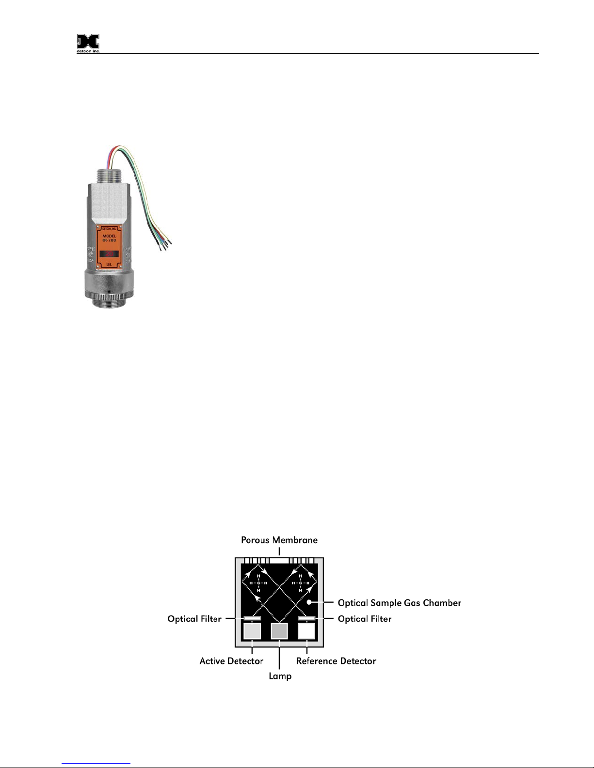
1.1.1 Non-Dispersive Infrared (NDIR) Optical Sensor Technology
The sensor technology is designed as a miniature pl ug-in replaceable component, whi ch can easily be chang ed
out in the field. The NDIR sensor consists of an infrared lamp source, two pyro electric detectors, and an optical
gas sample chamber. The lamp source pr oduces infrared radiation, which interacts with the target gas as it is
reflected through the optical gas sample chamber. The in frared radiati on co ntacts each of the two py ro electri c
detectors at the completion of the optical path. The “active” pyro electric detector is covered by a filter specific
to the part of the IR spectrum where the target gas absorbs light. The “reference” pyro electric detector is covered
by a filter specific to the non-absorbing p art of the IR spectrum. When the target gas is present, it absorbs IR
radiation and the signal output from the active detective decreases accordingly. The reference detector output
remains unchanged. The ratio of the act ive and reference detect or outputs are then used to compute the tar get
gas concentration.
The technique is referred to as non-selective and may be used to monitor most any combustible hydrocarbon
gas. The technique for CO
catalytic bead type sensors, Detcon IR sen sors are completely resistant to p oisoning from corrosive gases and
they can operate in the absence of an oxygen background. The sensors are characteristically stable and capable
of providing reliable performance for periods exceeding 5 years in most industrial environments.
is si milar except that the sensor provides a sel ective response to CO2. Unlike
2
Sensor is designed to
2
IR-700 Instruction Manual Rev. 4.3 Page 1 of 46
Figure 1 Sensor Cell Construction
Model IR-700
NOTE: The IR-700 sensor will not respond to combustible gases that are not hydrocarbons,
such as H2, NH3, CO, H2S….etc. It can only be used to measure hydrocarbon type gases.
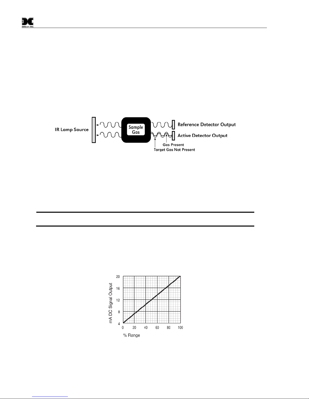
1.1.2 Principle of Operation
The target gas diffuses through a sintered stai nless steel flame arrestor and into the v olume of the sample gas
optical chamber. An alternating miniat u re la mp pro vid es a cy cli cal IR rad iation source, which reflects through
the optical gas sample chamber and termin ates at two pyro electric detectors. The active an d reference pyro
electric detectors each give an output which measures the intensity of the radiation contacting their surface. The
active detector is covered by an optical filter specific to the part of the IR spectrum where the target gas absorbs
light. The reference detector is covered by a filter specific to the non-absorbing part of the IR spectrum. When
present, the target gas absorbs a fraction of the IR radiation and the signal output from the active detector
decreases accordingly. The signal output of the reference detector remains unchanged in the presence of the
target gas. The ratio of the active/reference signal outputs is then used to compute the target gas concentration.
By using the ratio of the active/reference signal outputs, measurement drift caused by the changes in the intensity
of the IR lamp source or changes in the optical path’s reflectivity is prevented.
Figure 2 Principle of Operation
1.1.3 Performance Characteristics
The IR sensor maintains strong sensitivity to most all combustible hydrocarbon gases in the Lower Ex plosive
Limit (LEL) range, as shown in the response curve illustration below. When compared with the typical catalytic
bead LEL sensor, the IR sensor exhibits improved long-term zero and span stability. Typical zero calibration
intervals would be quarterly to semi-annual and typical span intervals would be semi-annual to annual.
However, actual field experience is always the best determination of appropriate calibration intervals.
The IR sensor generates different sign al sensitivity levels for different combustib le hydrocarbon target gases.
Unless otherwise specified the IR-700 sensor will be factory calibrated for methane service. If the target
hydrocarbon gas is other than metha ne, then t he unit w ill have t o be spa n cali brate d and conf igure d acc ordingl y
per this Instruction Manual.
Figure 3 Response Curve
IR-700 Instruction Manual Rev. 4.3 Page 2 of 46

Model IR-700
Program Switch #1
LED Display
Program Switch #2
Splash Guard Adapter
Locking Set-Screw
detcon inc.
LEL
MODEL
IR-700
RS-485
4-20mA
Display
Pre-Amp
Analog 4-20mA Out
Modbus™ RS-485 Output
Power In
Power Supply
1.2 Sensor Electronics Design
1.2.1 Intelligent Transmitter Module
The Intelligent Transmitter Module ( ITM) is a fully encapsulated micropro cessor-based pac kage that acc epts a
plug-in field replaceable combustible gas sensor and for IR-700 CO
Circuit functions include extensive I/O circuit protection, sensor pre-amplifier, on-board power supplies,
microprocessor, LED display, magnetic pro gramming switches, a linear 4-20mA DC output, and a Modbus™
RS-485 output. Magnetic program swi tche s l oc a t e d on e it he r s ide of the LED Display are activated via a handheld magnetic programming tool, thus allowing non-intrusive operator interface with the ITM. Calibration can
be accomplished without declassifying the area. El ectrical classifications are Class I, Divisi on 1, Groups B C
D, Class I, Zone 1, Group IIB+H
, and II 2G Ex d IIB+H2 Gb.
2
Plug-In
Sensor
Element
Micro-
Processor
Figure 4 ITM Circuit Functional Block Diagram
sensors, a plug-in replaceable CO2 sensor.
2
I/O
Circuit
Protection
1.3 Modular Mechanical Design
The Model IR-700 Sensor Assembly is completely modular and made up of four parts (See Figure 6 for
Assembly Breakaway):
1) IR-700 Intelligent Transmitter Module (ITM)
2) Field Replaceable Plug-in Infra-Red Gas Sensor
IR-700 Instruction Manual Rev. 4.3 Page 3 of 46
Figure 5 Sensor Assembly Front View

Model IR-700
Plug-in Replacable
Combustible
Hydrocarbon Sensor
Splash Guard
Housing Bottom
Assembly
O-Rings
Lens and LCD
Display
Housing Bottom
Locking Set-Screw
Magnetic
Programming
Switches
Intelligent Transmitter Module (ITM)
Micro-Processor controlled circuit
encapsulated in an explosion proof
housing.
detcon inc.
LEL
MODEL
IR-700
3) Model 700 Housing Bottom Assembly (contains the Housing Bottom, Flame Arrestor, Retaining Ring,
and rubber O-Rings)
4) Splash Guard.
NOTE: All metal components are const ructed from electro-polished 316 Stainless Steel in order to maximize
corrosion resistance in harsh environments.
Figure 6 Sensor Assembly Breakaway
1.4 Plug-in Replaceable Sensor
The Detcon IR combustible hydrocarbon gas sensor is a unique and miniaturized single-package optical design
that generates enough internal heat to prevent condensation. It is packaged as a true plug-in replaceable type
sensor with over-sized gold-plated connections that eliminate corrosion problems. It can be accessed and
replaced in the field very easily by releasing the l ocking scre w and unthrea ding the housin g bottom. T he Detcon
IR combustible hydrocarbon gas sensor and the CO
a 5-year pro-rated warranty. The expected service life is 5 years or greater.
Figure 7 IR Sensor Cell
gas sensor have an infinite shelf life, and are suppo rted by
2
IR-700 Instruction Manual Rev. 4.3 Page 4 of 46

Model IR-700
2. Installation
2.1 Operational Guidelines for Safe Use – HazLoc Certifications
1. It is recommended for end-users to read and reference the procedures described in IEC 60079-
29-2 for guidance on the proper installation, operation, and servicing of this type of
combustible gas detectors.
2. Install sensor only in areas with classifications matching with t hose described on the ATEX approval
label. Follow all warnings listed on the label.
3. Detector is performance tested to the ANSI/UL 12.13.01:2013 Performance Requirements of
Detectors for Flammable Gases. Performance Testing was completed by CSA Group on
March 28, 2018. This Model IR-700 detector is performance tested only for methane gas
measurement in the 0-100 %LEL (0-5% by volume) range and with use of Accessory PN 6131200000-700 Sensor Splashguard with integral Cal Port. There are no special conditions for
use other than what is specified here in Section 2.1 of Instruction Manual.
Figure 8 HazLoc Certification Approval Label
4. Ensure that the sensor is properly threaded into a suitable flameproof rated junction box with a
downward pointing female ¾” NPT threaded connection. The sensor should be threaded up at least 5
full turns until tight, with the LED display facing forward (+/-15°). Minimize use of T eflon Tape, or
any type of non-conductive pipe thread coating on the NPT threaded connection.
5. A good ground connection should be verified between the sensor’s metal enclosure and the junction
box. If a good ground conne cti on is n ot m ade, the s ensor c an be g rounded to th e junc tion box us ing t he
sensor’s external ground lug. A lso verify a g ood ground connectio n betwee n the juncti on box and e arth
ground. Installer shall use ring terminal to make connection to earth ground to be secured by screw and
lock washer on sensor housing.
6. Ensure that the Housing Bottom a nd plug-in sensor are installed during ope ration. The Housing Bottom
should be threaded tightly to the Intelligent Transm itter Module. The locking s etscrew (M3.5 x 0.6 6g6h
Stainless Steel Allen set screw cup point with yield strength of greater than 40,000 PSI, typical 80,000
PSI) should then be tightened down to keep the Housing Bottom from being inadvertently removed or
from becoming loose under vibration. The locking setscrew ensures that Housing Bottom is only
removable by authorized personnel with the use of special tools. A M1.5 Allen Wrench is required. If
screw requires replacement, only an identical screw may be used.
7. Removal of the Housing Bot tom violate s the Ex d protec tion method a nd hence pow er must be removed
from the sensor prior its safe removal.
8. The screws holding down the retaining plate label are special fastener s of type Stainless Steel, Phillips
Pan-head Machine screw, M3 x 0.5 6g6 h having yield strength of greater than 40,000 PSI, typical 80,000
PSI. If screw requires replacement, only an identical screw may be used.
IR-700 Instruction Manual Rev. 4.3 Page 5 of 46

Model IR-700
NOTE: Methane is lighter than air. Most other combustible hydrocarbon gases are heavier than
air to determine appropriate placement.
9. Proper precautions should be taken during installation and maintenance to avoid the build-up of static
charge on the plastic components of t he sens or. Thes e include the splas hguard and s plashgua rd adapt er.
10. Do not operate the sensor outside of the stated operating temperature limits.
11. Do not operate the sensor outside the stated operating limits for voltage supply.
12. These sensors meet E N60079-0:2012, EN60079-1:2007.
2.2 Sensor Placement
Selection of sensor location is critical to the overall safe performance of the product. Five factors play an
important role in selection of sensor locations:
(1) Density of the gas to be detected
(2) Most probable leak sources within the industrial process
(3) Ventilation or prevailing wind conditions
(4) Personnel exposure.
(5) Maintenance access.
Density
Placement of sensors relative to the density of the target gas is such that sensors for the detection of heavier than
air gases should be located within 4 feet of grade as these heavy gases will tend to settle in low lying areas. For
gases lighter than air, sensor placement should be 4-8 feet above grade in open areas or in pitched areas o f
enclosed spaces.
air. Compare the molecular weight, density, or specific gravity of the target gas(es) with that of
Leak Sources
The most probable leak sources within an industrial process include flanges, valves, and tubing connections of
the sealed type where seals may either fail or wear. Other leak sources are best determined by facility engineers
with experience in similar processes.
Ventilation
Normal ventilation or prevailing wind conditions can dictate efficient location of gas sensors in a manner where
the migration of gas clouds is quickly detected.
Personnel Exposure
The undetected migration of gas c louds should n ot be allow ed to approa ch conc entr ated pe rsonnel ar eas suc h as
control rooms, maintenance or warehouse buildings. A more general and applicable thought toward selecting
sensor location is combining leak source and perimeter protection in the best possible configuration.
Maintenance Access
Consideration should be given to providing easy access for maintenance personnel. Consideration should also
be given to the consequences of close proximity to contaminants that may foul the sensor prematurely.
IR-700 Instruction Manual Rev. 4.3 Page 6 of 46

Model IR-700
NOTE: In all installations the gas sensor should point straight down. Refer to Figure 13.
Improper sensor orientation may result in false r eadings and permanent sensor damage.
Additional Placement Considerations
The sensor should not be position ed wher e it may be spray ed o r coated with surf ace con tamin ating substan ces.
Painting sensor assemblies is prohibited.
Although the sensor is designed to be RFI resistant, it should not be mounted in close proximity to high-powered
radio transmitters or similar RFI generating equipment.
When possible, mount the sensor in an area void of high wind, accumulating dust, rain, or splashing from hose
spray, direct steam releases, and continuous vibration. If the sensor cannot be mounted away from these
conditions then make sure the Detcon Harsh En vironment Splashguard accessory is used.
Do not mount in locations where temperatures will exceed the operating temperature limits of the sensor. Where
direct sunlight leads to exceeding the high temperature-operating limit, use a sunshade to help reduce
temperature.
2.3 Sensor Contaminants and Interference
Detcon IR-700 combustible hydrocarbon gas sensors may be adversely affected by exposure to certain airborne
substances. Loss of sensitivity or corrosion may be gradual if such materials are present in sufficient
concentrations.
The performance of the IR sensor may be impaired during operation in the presence of substances that can cause
corrosion on gold plating. Other inhibiting substances are th ose that can coat the internal walls of the optical
chamber and reduce reflectivity. These inclu de but are not limited to heavy oil deposits, dust/powder, water
condensation, and salt forma tion. Contin uous and high concentra tions of corrosi ve gases (such as Cl
…etc.) may also have a detrimental long-term effect on the sensor’s service life.
The presence of such substances in an area does n ot preclude the use of this sensor technology, although it is
likely that the sensor lifetime will be shorter as a result. Use of this sensor i n these environments may requi re
more frequent calibration checks to ensure safe system performance.
For the IR-700 Combustible gas sensors there are no known cross-interference gases that are not combustible
hydrocarbon gases. For the IR-700 CO
Sensor, there are no known cross interference gases.
2
, H2S, HCl
2
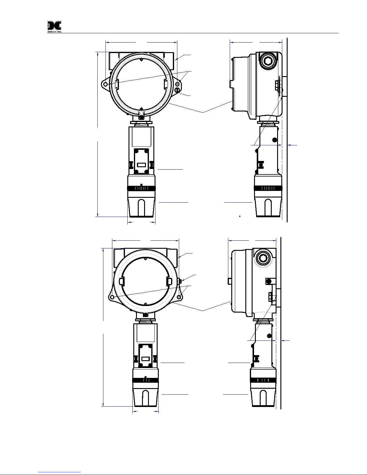
2.4 Mounting Installation
The IR-700 sensor assembly is designed to be threaded into a ¾” female NPT fitting of a standard cast metal
Explosion-Proof Enclosure or Junct ion Box. Thread the sensor up unti l t ight (5 turns is typically expe c t e d) and
until the display is facing the direction that t he sensor will normally be viewed and accessed.
The IR-700 should be vertically oriented so that the sensor points straight downward. The explosion-proof
enclosure or junction box would then typically be mounted on a wall or pole. Detcon provides a standard
selection of junction boxes available as sensor accessories (See Figures 9, 10, 11, and 12 below), but any
appropriately rated enclosure with a down war d facing ¾” NPT female connection will suffice.
When mounting on a wall, it is recommended to use a 0.25”-0.5” spacer underneath the mounting ears of the
Detcon standard J-Box to offset the sensor assembly from the wall and create open access around the sensor
assembly. Spacing requirements for other junction boxes may vary.
IR-700 Instruction Manual Rev. 4.3 Page 7 of 46

Model IR-700
Male 3/4" NPT Threads
Sensor Assembly
Splash Guard
2.125"
7.8"
Typ.
Ferrite Cylinder
Sensor Wires
2"
0.3"
5.48"
detcon inc.
LEL
MODEL
IR-700
When mounting on a pole, secure the Junction Box to a suitable mounting plate and attach the mounting plate
to the pole using U-Bolts. (Pole-Mounting brackets for Detcon J-Box accessories are available separately.)
Figure 9 Outline and Mounting Dimensions (Sensor Assembly only)
IR-700 Instruction Manual Rev. 4.3 Page 8 of 46
Model IR-700
4"
3/4" NPT
Explosion Proof Enclosure
Junction-Box
Sensor Assembly
Splash Guard
(Detcon's SS Junction-Box shown)
2.125"
5.5"
12.5"
Typ.
Mounting
Bolt
Use Spacers to move the J-Box
and Sensor Assembly away
from the wall at least 0.25-0.5"
to allow access to Sensor.
Wall
(or other
mounting surface)
Ø0.265"
Spacer
Mounting Holes
8-32 Thread
Ground Point
detcon inc.
LEL
MODEL
IR-700
4"
3/4" NPT
Explosion Proof Enclosure
Junction-Box
Sensor Assembly
Splash Guard
(Detcon's Aluminum Junction-Box shown)
2.125"
5.5"
13"
Typ.
Mounting
Bolt
Use Spacers to move the J-Box
and Sensor Assembly away
from the wall at least 0.25-0.5"
to allow access to Sensor
Wall
(or other
mounting surface)
Ø0.265" x2
Spacer
Mounting Holes
8-32 Thread
Ground Point
detcon inc.
LEL
MODEL
IR-700
Figure 10 Outline and Mounting Dimensions (Stainless Steel Junction Box)
Figure 11 Outline and Mounting Dimensions (Aluminum Junction Box)
IR-700 Instruction Manual Rev. 4.3 Page 9 of 46
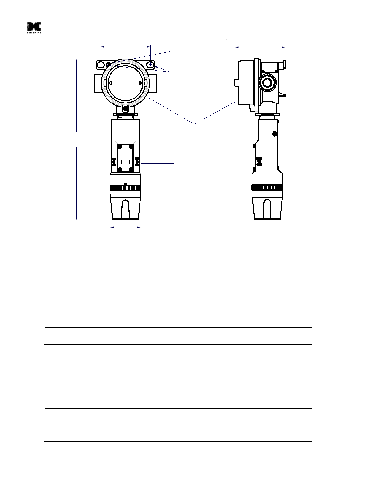
Model IR-700
3.5"
Explosion Proof Enclosure
Junction-Box
Sensor Assembly
Splash Guard
(Detcon's Mini SS Junction-Box shown)
2.125"
3.45"
11"
Typ.
Mounting Holes
8-32 Thread
Ground Point
Ø0.4" x .475"
detcon inc.
LEL
MODEL
IR-700
NOTE: If a conduit run exits the secondary port, repeat the installation technique shown in
Figure 13.
NOTE: For products utilizing the aluminum junction box option, the conduit seal shall be placed
Hinds type EYS2, EYD2 or equivalent are suitable for this purpose.
Figure 12 Outline and Mounting Dimensions (Mini Stainless Steel Junction Box)
2.5 Electrical Installation
The Sensor Assembly should be install ed in accord ance with local electrical co des. The sen sor assemblies are
CSA/NRTL approved (US and Canada) for Class I, Division 1, Groups B, C, & D area classif ications, an d are
ATEX Approved for II 2G Ex d IIB+H
Proper electrical installation of the gas sensor is critical for conformance to Electric al Codes and to avoid dam age
due to water leakage. Refer to Figure 13 and Figure 14 for proper electrical installation.
In Figure 12, the drain allows H
2
assembly. The electrical seal fitting is required to meet the National Electr ical Code per NEC Article 500-3d
(or Canadian Electrical Code Handbook Part 1 Section 18-154). Requirements for locations of electrical seals
are covered under NEC Article 501-5. Electrical seals also act as a secondary seal to prevent water from entering
the wiring terminal enclosure. However, they are not designed to provide an absolute water-tight seal, especially
when used in the vertical orientation.
at the entry to the junction box (see Figure 13 as an example). For products utilizing the stainless
steel junction box option, the conduit seal shall be placed within 18” of the enclosure. Crouse
Gb area classifications.
2
O condensation inside the conduit run to safely drain away from the sensor
IR-700 Instruction Manual Rev. 4.3 Page 10 of 46

Model IR-700
NOTE: The Detcon Warranty does not cover wat er damage resulting from water leaking into
encapsulated, only the wire terminations could get wet. Moisture could cause abnormal
would not be expected.
Plug any unused
ports
Explosion Proof
Housing
(J-Box)
Drain
IR-700
Sensor
Assembly
Conduit
"T"
EYS Seal Fitting
(+)
mA
(-)
A(+)
B(-)
Wiring to
Sensor Assembly
Wht
Blu
Red
Grn
Blk
Explosion
Proof
Junction Box
(+)
mA
(-)
N/U
A(+)
B(-)
Customer
Supplied Wiring
Transient Protection Module
(TPM) P/N 500-003087-100
Mount TPM in Explosion
Proof Enclosure to ground
unit properly. Mount to
bottom of enclosure using
6-32 screws.
+
6-Pin Pheonix Plug
P/N 306-175705-100
detcon inc.
LEL
MODEL
IR-700
NOTE: Any unused ports should be blocked with suitabl e ¾” male NPT plugs. Detc on Supplies
NPT, use an appropriate male plug of like constr uction material.
the enclosure through the conduit connections. However, since the electronics are 100% epoxy
operation and possibly corr osion to the terminal connections, but permanent damage to the sensor
Figure 13 Typical Installation
one ¾” NPT male plug with their accessory J-box enclosures. If connecti ons are other th an ¾”
2.6 Field Wiring
Detcon Model IR-700 combustible hydrocarbon gas sensor assemblies require three conductor connections
between power supplies and host electron ic controller’s 4-20mA output, and 2 conductor connections for the
Modbus™ RS-485 serial interface. Wiring designations are + (DC), – (DC), mA (sens or signal), and Modb us™
RS-485 A (+), and B (-). Maximum wire size for termination in the Detcon J-Box accessory is 14AWG.
IR-700 Instruction Manual Rev. 4.3 Page 11 of 46
 Loading...