

Page 1
INSTRUCTION MANUAL
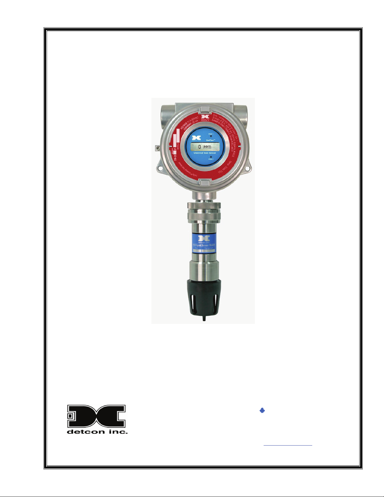
Detcon Model DM-200
DM-200 Toxic Gas Sensors
DM-200 O
Covers all ranges of electrochemical and O2 deficiency sensors
offered in the Detcon Product Line
September 04, 2009 • Document #3454 • Revision 2.0
Deficiency Sensors
2
DETCON, Inc.
3200 Research Forest Dr.,
The Woodlands, Texas 77387
Ph.281.367.4100 / Fax 281.298.2868
0Hwww.detcon.com
Page 2

Model DM-200
This page left intentionally blank
Model DM-200 ii
Page 3

Model DM-200
Table of Contents
1. Introduction ................................................................................................................................................. 1
1.1 Description.......................................................................................................................................... 1
1.2 Sensor Technology.............................................................................................................................. 1
1.3 Universal Transmitter Module (UTM) ............................................................................................... 2
1.4 Intelligent Sensor Module (ISM) ........................................................................................................ 3
2. Installation ................................................................................................................................................... 4
2.1 Sensor Placement/Mounting ............................................................................................................... 4
2.2 Interference Data................................................................................................................................. 5
2.3 Field Wiring Table (4-20 mA output)................................................................................................. 6
2.4 Sensor Location .................................................................................................................................. 6
2.5 Local Electrical Codes ........................................................................................................................ 7
2.6 Installation Procedure ......................................................................................................................... 7
2.7 Remote Mounting Applications.......................................................................................................... 8
2.8 Start Up ............................................................................................................................................... 9
2.9 Initial Operational Tests...................................................................................................................... 9
3. Operation ................................................................................................................................................... 10
3.1 Normal Operation ............................................................................................................................. 10
3.2 Calibration Mode .............................................................................................................................. 10
3.3 Program Mode .................................................................................................................................. 10
3.4 Calibration - Toxics .......................................................................................................................... 13
3.4.1 Calibration Procedure - Zero ........................................................................................................ 13
3.4.2 Calibration Procedure - Span........................................................................................................ 13
3.4.3 Calibration Frequency .................................................................................................................. 16
3.5 Calibration – Oxygen........................................................................................................................ 16
3.5.1 O2 Calibration Procedure - Span................................................................................................... 16
3.5.2 O2 Calibration Procedure - Zero ................................................................................................... 18
3.6 Status of Programming and ISM Parameters.................................................................................... 18
3.6.1 View Program Status.................................................................................................................... 19
3.6.2 Set Date ........................................................................................................................................ 19
3.7 Program Features .............................................................................................................................. 20
4. Service and Maintenance........................................................................................................................... 21
4.1 Exchanging the ISM ......................................................................................................................... 21
4.1.1 Physical Exchange........................................................................................................................ 21
4.1.2 Establishing Communication........................................................................................................ 21
4.1.3 Maintaining "Biased" ISM’s using the Battery Back-up Module (Optional)............................... 21
4.2 Exchanging Electrochemical Sensors ............................................................................................... 22
4.3 Display Contrast Adjust.................................................................................................................... 23
5. Trouble Shooting Guide ............................................................................................................................ 24
6. Customer Support and Service Policy ....................................................................................................... 26
7. Warranty .................................................................................................................................................... 26
8. Spare Parts ................................................................................................................................................. 27
9. Specifications............................................................................................................................................. 29
Appendix A ........................................................................................................................................................ 31
Interference Table .......................................................................................................................................... 31
Appendix B ........................................................................................................................................................ 38
Revision Log.................................................................................................................................................. 38
Appendix C ........................................................................................................................................................ 39
Drawings and Diagrams................................................................................................................................. 39
Model DM-200 iii
Page 4

Model DM-200
Table of Figures
Figure 1 UniTox Sensor assembly ..................................................................................................................... 1
Figure 2 Sensor Cell Diagram ............................................................................................................................ 2
Figure 3 Function Block diagram....................................................................................................................... 2
Figure 4 Universal Transmitter Module ............................................................................................................. 3
Figure 5 4-20 mA Field Wiring.......................................................................................................................... 3
Figure 6 Intelligent Sensor Module.................................................................................................................... 4
Figure 7 Recommended Electrical Installation Method..................................................................................... 5
Figure 8 Sensor assembly orientation................................................................................................................. 7
Figure 9 Universal Transmitter Module (Bottom view)..................................................................................... 8
Figure 10 Remote Mount Configuration .............................................................................................................. 8
Figure 11 Magnetic Programming Tool............................................................................................................. 11
Figure 12 Software Flow Chart .......................................................................................................................... 12
Figure 13 Auto Span Sequence - Toxics ............................................................................................................ 15
Figure 14 Auto Span Sequence - Oxygen .......................................................................................................... 17
Figure 15 UTM-ISM breakaway.........................................................................Error! Bookmark not defined.
Figure 16 ISM Battery Backup Module ............................................................................................................. 22
Figure 17 Sensor Cell Replacement ................................................................................................................... 23
Figure 18 Spare parts Breakaway........................................................................ Error! Bookmark not defined.
Shipping Address: 3200 A-1 Research Forest Dr., The Woodlands Texas 77381
Mailing Address: P.O. Box 8067, The Woodlands Texas 77387-8067
Phone: 888.367.4286, 281.367.4100 • Fax: 281.292.2860 • 1H
Model DM-200 iv
www.detcon.com •
Page 5
Model DM-200
1. Introduction
1.1 Description
Detcon UniTox™ Model 200 Series universal toxic sensors are non-intrusive “Smart” sensors designed to
detect and monitor for toxic gases in the ppm range. The UniTox™ sensor family also includes ambient O
detection in the 0-25% range. UniTox™ sensors are designed to operate as standard two-wire 4-20 mA looppowered devices. Their intrinsically safe electronics design, when used with specified intrinsically safe field
wire barriers, conforms to a Class 1, Division 1, Group A, B, C, D area classification. The Sensor Assembly
includes a metal Nema 7 junction box and electropolished 316SS ISM assembly
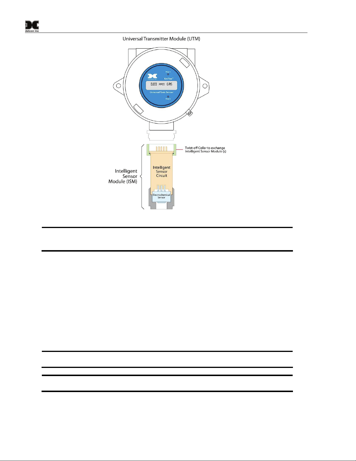
The UniTox™ gas sensor consists of two major components: 1) the Universal Transmitter Module (UTM) and
2) the gas/range specific Intelligent Sensor Module (ISM). The universality of the design allows any ISM type
to be plugged into any UTM with seamless operation. The ISM consists of an electrochemical toxic gas
sensor and associated PCB providing pre-amplifier, microprocessor, and memory storage functions.
A 2-line 16-character alpha/numeric LCD is used to display sensor readings and provides the user interface
with the sensor’s menu driven features via a hand-held programming magnet.
Typical ranges of detection are 0-1ppm, 0-10ppm, 0-25ppm, 0-50 ppm, and 0-100ppm. Other ranges are
available and all ranges are covered by this manual. To determine model number, gas type, and range of
detection, reference the labeling on the ISM or refer to the instructions found in Section 10 (View Program
Status).
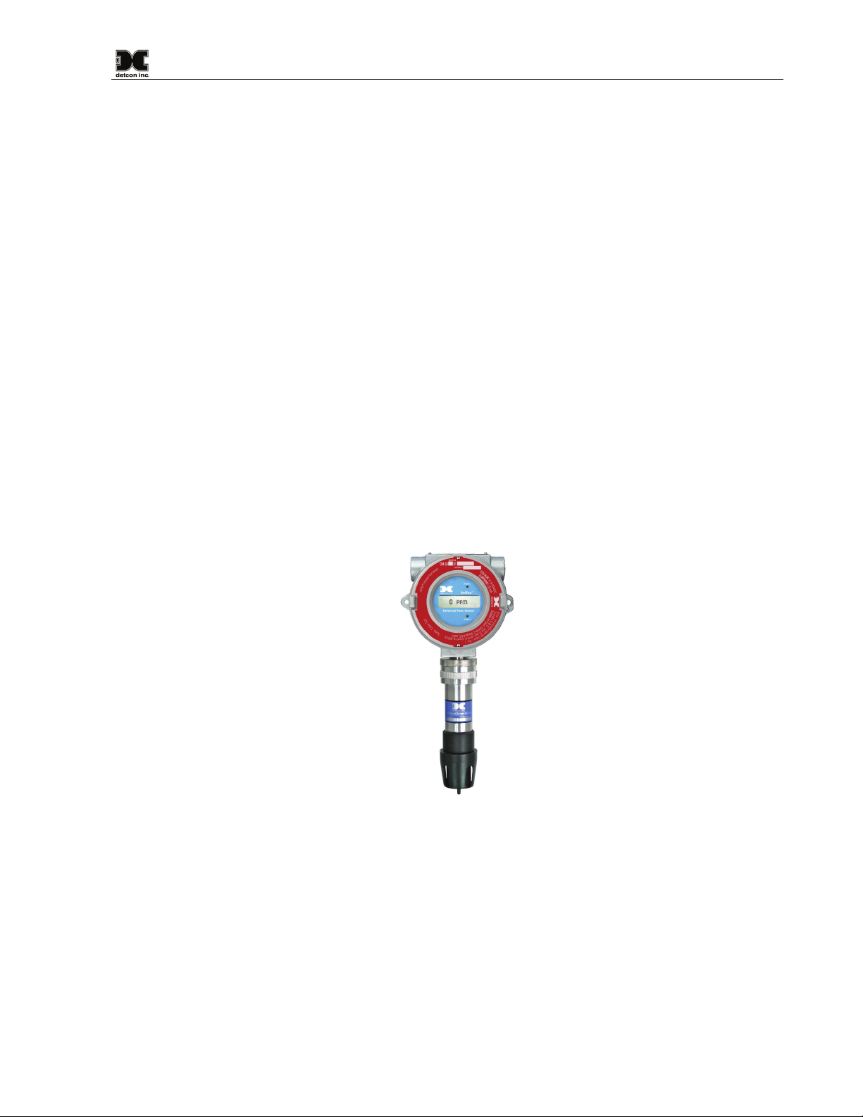
2
Figure 1 UniTox Sensor assembly
1.2 Sensor Technology
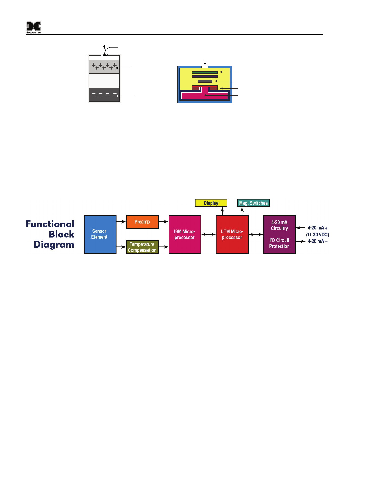
The sensors are electrolytic chemical cells. Each cell consists of three electrodes embedded in an electrolyte
solution, housed beneath a diffusion membrane. Sensitivity to specific target gases is achieved by varying
composition of any combination of the sensor components. Good specificity is achieved in each sensor type.
The cells are diffusion limited via small capillary barriers resulting in long service life of up to 3 or more
years. The oxygen cell is of the two-electrode, galvanic metal air battery type that functions as a direct current
generator proportional to the amount of oxygen adsorption.
DM-200 Instruction Manual Rev. 2.0 Page 1 of 40
Page 6
d
Model DM-200
Air Supply
Diffusion Barrier
Diffusion Barrier
Cathode
Electrolyte
Solution
Anode
Construction of Galvanic O2 Cell
Construction of Electrochemical Sensor
Sensing Electrode
Reference Electro
Counter Electrode
Electrolyte Reserv
Figure 2 Sensor Cell Diagram
The Method of detection is by an electrochemical reaction at the surface of an electrode called the sensing
electrode. Air and gas diffuse through the capillary diffusion barrier. The controlling circuit maintains a small
external operating voltage between the sensing and counter electrodes of the proper bias and magnitude so that
no current flows to or from the reference electrode while its potential is maintained at the correct fixed voltage
— usually ground. The electrochemical reaction creates a change in current flow from the counter electrode to
the sensing electrode. This change in current is proportional to the gas concentration and is reversible. The
quick response of the sensor results in continuous monitoring of ambient air conditions
.
Figure 3 Function Block diagram
1.3 Universal Transmitter Module (UTM)
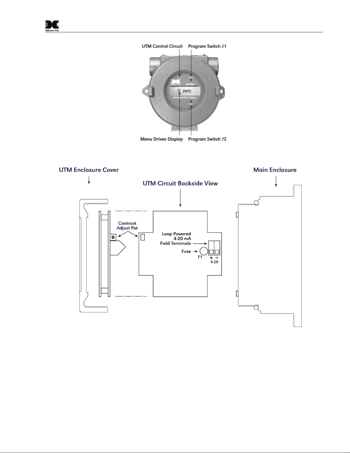
The UTM is microprocessor based, and is packaged as a field replaceable module mounted in an explosion
proof enclosure. This facilitates easy replacement and minimum down time. Circuit functions include a PIC
microprocessor, 2-line alphanumeric display, magnetic programming switches, and a linear 4-20 mA DC
output. Field wiring is terminated on the bottom side of the UTM. The UTM also provides an easily
accessible LCD contrast adjust pot and a protective input fuse (refer Figure 5 below). Calibration can be
acco
mplished without removing the cover. The low power intrinsically safe electronics design provides for an
area classification, which is Class 1; Division 1: Groups B, C, D.
DM-200 Instruction Manual Rev. 2.0 Page 2 of 40
Page 7
Model DM-200
Figure 4 Universal Transmitter Module
Figure 5 4-20 mA Field Wiring
1.4 Intelligent Sensor Module (ISM)
The ISM is microprocessor-based and is packaged as a plug-in replaceable module that facilitates easy
replacement and minimum downtime. The module is composed of sensor cell and ISM circuitry, permanently
potted in epoxy, and retained within a plug-in stainless steel mechanical assembly. Circuit functions include
an electrochemical sensor pre-amplifier, PIC microprocessor, and memory data storage. The ISM plugs into
the UTM via 5 rigid gold plated pins and is then secured via a threaded machined collar that screws on and
provides mechanical stability and a water-tight seal.
DM-200 Instruction Manual Rev. 2.0 Page 3 of 40
Page 8
Model DM-200
Figure 6 Intelligent Sensor Module
NOTE: The splashguard adapter is threaded and then secured to ISM housing using a setscrew.
To replace sensor cell, remove setscrew from splashguard adapter, unscrew splashguard
adapter from housing, replace sensor then re-secure splashguard adapter using setscrew.
2. Installation
2.1 Sensor Placement/Mounting
Sensor location should be reviewed by facility engineering and safety personnel. Area leak sources and
perimeter mounting are typically used to determine number and location of sensors. The sensors are generally
located 2 - 4 feet above grade.
Optimum performance of ambient air/gas sensor devices is directly related to proper location and installation
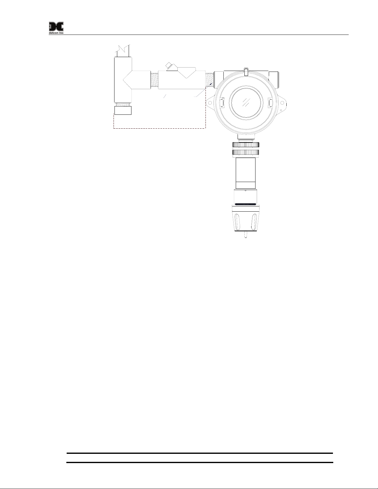
practices. Refer Figure 7 for recommended electrical installation method
NOTE: For Intrinsically Safe installation, reference drawing #2633 in Section Error!
Reference source not found. Error! Reference source not found.
NOTE: Intrinsically Safe barriers recommended for use include: MTL P/N 7706, P&F P/N
Z706, and R.Stahl P/N 9001/51-280-091-14
DM-200 Instruction Manual Rev. 2.0 Page 4 of 40
Page 9
Model DM-200
Conduit
Drain
2.2 Interference Data
"T"
Recommended
Electrical Installation
Figure 7 Recommended Electrical Installation Method
EYS Seal Fitting
3
" NPT Fitting
4
Method
UniTox™ Model 200 series electrochemical sensors
are subject to interference from other gases. This
interaction is shown in the in the table in Table 4
Appendix A
Interference Table
as the relation between the amount of the interfering gas applied to the sensor, and the corresponding reading
that will occur. All measurements are in ppm unless otherwise noted.
The table is laid out with the Gas type of each UniTox™ sensor in a column on the left side of the page. The
interfering gases are listed in a row across the top of the page. Each page lists all Model Numbers but 5 pages
are necessary to list all interfering gases, thus each page is a repeat of the full line of Detcon UniTox™
sensors. Be sure to reference each page to ascertain the full listing of interfering gases for a particular
UniTox™ sensor.
In example: The first listing shows that the C2H30 Acetyldehyde sensor will have an interference reading of
340 ppm if 40 ppm of C2H2 (Acetylene) is applied.
NOTE: Interference factors may differ from sensor to sensor and with lifetime. It is not
DM-200 Instruction Manual Rev. 2.0 Page 5 of 40
Page 10
Model DM-200
advisable to calibrate with interference gases. They should be used only as a guide.
2.3 Field Wiring Table (4-20 mA output)
Detcon UniTox™ toxic gas sensor assemblies require two-conductor connections between power supplies and
host electronic controllers. Wiring designators are + (DC), and – (DC). Maximum single conductor resistance
between sensor and controller is 10 ohms. Maximum wire size for termination in the sensor assembly terminal
board is 14 gauge.
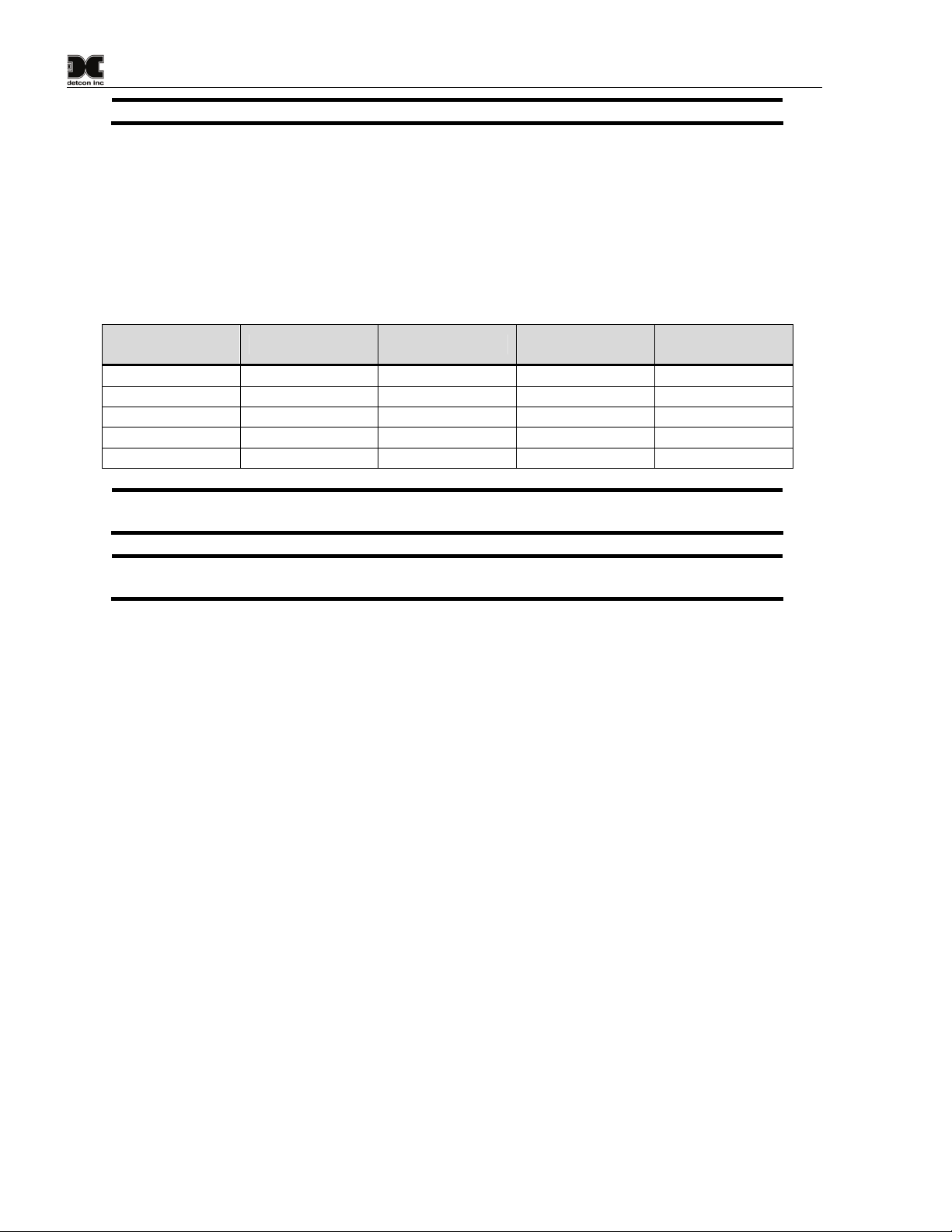
Table 1 Wire Gauge vs. Distance
AWG Wire Dia. Meters Feet
22 0.723mm 700 2080 3A
20 0.812mm 1120 3350 5A
18 1.024mm 1750 5250 7A
16 1.291mm 2800 8400 10A
14 1.628mm 4480 13,440 20A
NOTE: This wiring table is based on stranded tinned copper wire and is designed to serve as a
reference only.
NOTE: Shielded cable may be required in installations where cable trays or conduit runs
include high voltage lines or other sources of induced interference.
Over-Current
Protection
2.4 Sensor Location
Selection of sensor location is critical to the overall safe performance of the product. Five factors play an
important role in selection of sensor locations:
(1) Density of the gas to be detected
(2) Most probable leak sources within the industrial process
(3) Ventilation or prevailing wind conditions
(4) Personnel exposure
(5) Maintenance access
Density - Placement of sensors relative to the density of the target gas is such that sensors for the detection of
heavier than air gases should be located within 2-4 feet of grade as these heavy gases will tend to settle in low
lying areas. For gases lighter than air, sensor placement should be 4-8 feet above grade in open areas or in
pitched areas of enclosed spaces.
Leak Sources - Most probable leak sources within an industrial process include flanges, valves, and tubing
connections of the sealed type where seals may either fail or wear. Other leak sources are best determined by
facility engineers with experience in similar processes.
Ventilation - Normal ventilation or prevailing wind conditions can dictate efficient location of gas sensors in a
manner where the migration of gas clouds is quickly detected.
Personnel Exposure - The undetected migration of gas clouds should not be allowed to approach concentrated
personnel areas such as control rooms, maintenance or warehouse buildings. A more general and applicable
thought toward selecting sensor location is combining leak source and perimeter protection in the best possible
configuration.
DM-200 Instruction Manual Rev. 2.0 Page 6 of 40
Page 11
Model DM-200
Maintenance Access
Consideration should be given to easy access by maintenance personnel as well as the consequences of close
proximity to contaminants that may foul the sensor prematurely.
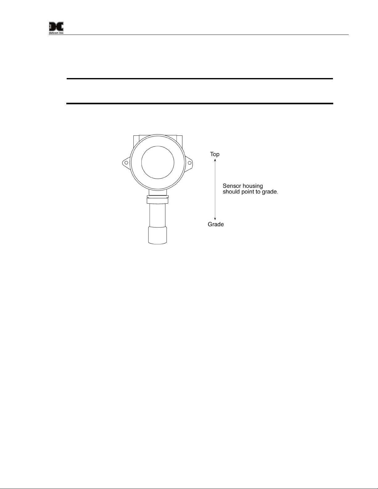
NOTE: In all installations, the sensor element in SS housing points down relative to grade
Figure 8. Improper sensor orientation may result in false reading and
permanent sensor
damage.
Figure 8 Sensor assembly orientation
2.5 Local Electrical Codes
Sensor and transmitter assemblies should be installed in accordance with all local electrical codes. Use
appropriate conduit seals. Drains & breathers are recommended.
2.6 Installation Procedure
a) Securely mount the sensor junction box in accordance with recommended practice. See dimensional
drawing in Section Error! Reference source not found. .
b) Unscrew the enclosure cover. Release the UTM assembly by removing and retaining two mounting
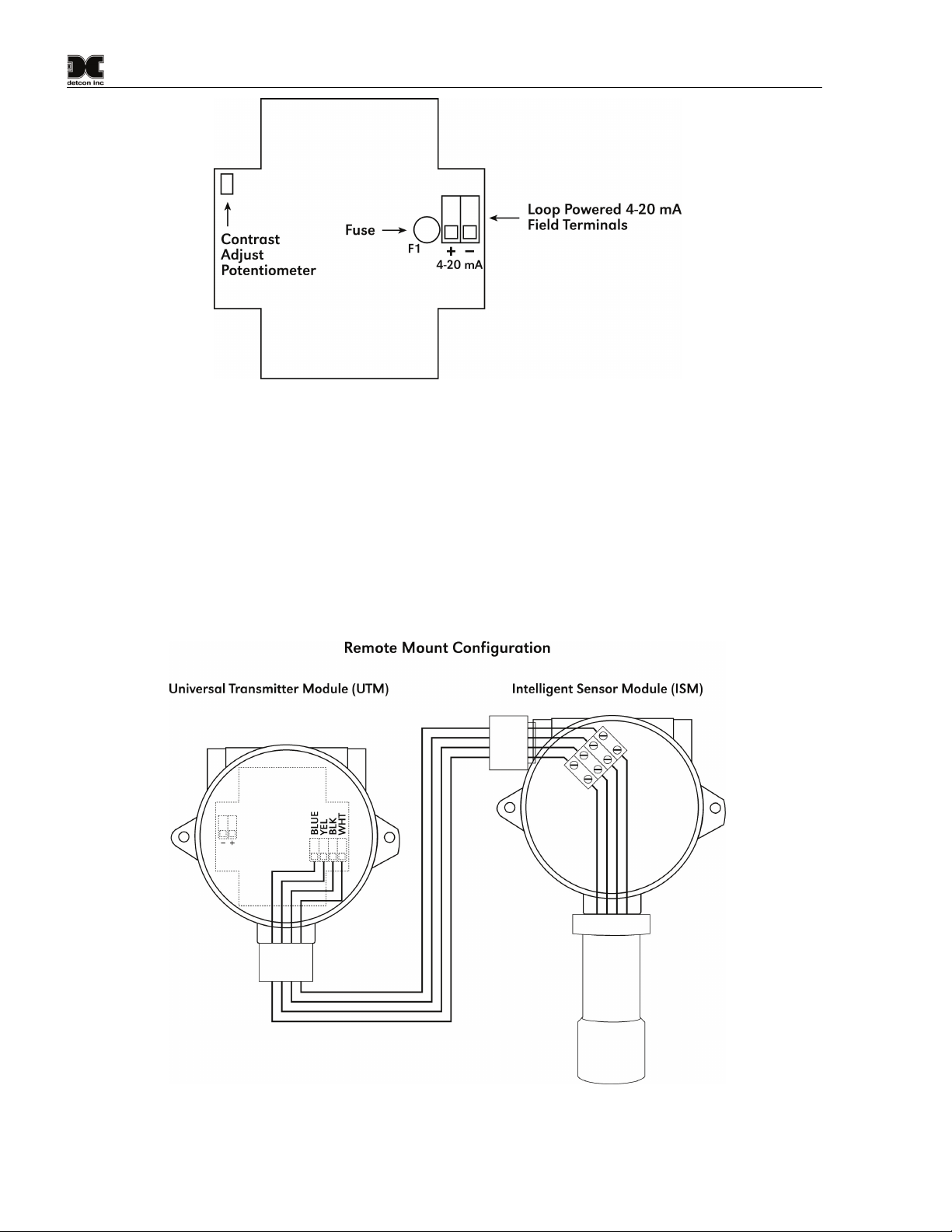
screws and washers on the transmitter. Observing correct polarity, connect the loop power field
wiring to the terminals labeled “+” and “–” 4-20 mA (reference Figure 9). Reinstall transmitter and
secure using scre
ws and washers. Reinstall enclosure cover.
DM-200 Instruction Manual Rev. 2.0 Page 7 of 40
Page 12
Model DM-200
Figure 9 Universal Transmitter Module (Bottom view)
2.7 Remote Mounting Applications
Some sensor mounting applications require that the gas sensor head be remotely mounted away from the
sensor transmitter. This is usually true in instances where the gas sensor head must be mounted in a location
that is difficult to access. Such a location creates problems for maintenance and calibration activities. Detcon
provides the UniTox™ Model Series 200 in a remote-mount configuration in which the sensor and the
transmitter are provided in their own condulet housing and are interfaced together with a four conductor cable.
The separation distance can be up to 75 feet. Refer Figure 10 for wiring diagram
Figure 10 Remote Mount Configuration
DM-200 Instruction Manual Rev. 2.0 Page 8 of 40
Page 13

Model DM-200
2.8 Start Up
Upon completion of all mechanical mounting and termination of all field wiring, apply system power and
observe the following normal condition:
A temporary upscale reading will occur as the sensor powers up. This upscale reading should clear to 0ppm
within approximately 30 minutes of turn-on, assuming there is no gas in the area of the sensor.
NOTE: If the display contrast needs adjustment, refer to Section 4.3 Display Contrast Adjust
Zero Clearing with Biased Cells
Some electrochemical sensors are biased with an excitation voltage. When power to the sensor is lost, this
bias voltage slowly decays. When power is restored after long periods of time (multiple hours), a surge in
sensor output takes place and a long and slow re-establishing of the sensor’s zero baseline takes place. This
re-stabilization time may range from 1 hour to 24 hours depending on the type of sensor and range of
operation. The sensor types that this applies to are the following: HCl, NO, NH3 (DM-202-NH3), plus all the
VOC sensors, C2H30, C2H2, C3H3N, C4H6, CS2, COS, C2H6S, C3H5OCL, C2H5OH, C2H4, C2H4O,
CH2O, CH3OH, C4H4S, C4H6O2, C6H5CH3 and C2H3CL.
If this characteristic is problematic for your specific application, a battery backup or uninterruptible power
supply is recommended.
2.9 Initial Operational Tests
After a warm up period has been allowed for, the sensor should be checked to verify sensitivity to its target
gas.
Material Requirements
* Span gas containing the target gas in air or nitrogen. It is recommended that the target gas
concentration be 50% of scale at a controlled flow rate of 500 ml/min. For example, a Model DM200-H2S UniTox™ sensor in the range 0-100ppm would require a test gas of 50ppm H2S. For a
sensor with a range of 0-10ppm a test gas of 5ppm is recommended, etc.
For oxygen, use test gas containing 100% nitrogen.
a) Attach tubing to the center port connection of Splashguard. Apply the test gas at a controlled flow rate
of 500ml/m. Observe that the LCD display increases to a level of 20% of range or higher. For oxygen,
observe that the display decreases to a level of 3% or less.
b) Remove the test gas and observe that the LCD display decreases to “0 PPM”. For oxygen, observe
that the LCD display increases back close to 20.9%.
Initial operational tests are complete. Detcon toxic gas sensors are pre-calibrated prior to shipment and in
most cases will not require significant adjustment on start up. However, it is recommended that a complete
calibration test and adjustment be performed within 24 hours of installation. Refer to calibration instructions
in later text.
DM-200 Instruction Manual Rev. 2.0 Page 9 of 40
Page 14

Model DM-200
3. Operation
Operating software is menu listed with operator interface via the two magnetic program switches located under
the enclosure cover. The two switches are referred to as “PGM 1” and “PGM 2”. The menu list consists of 3
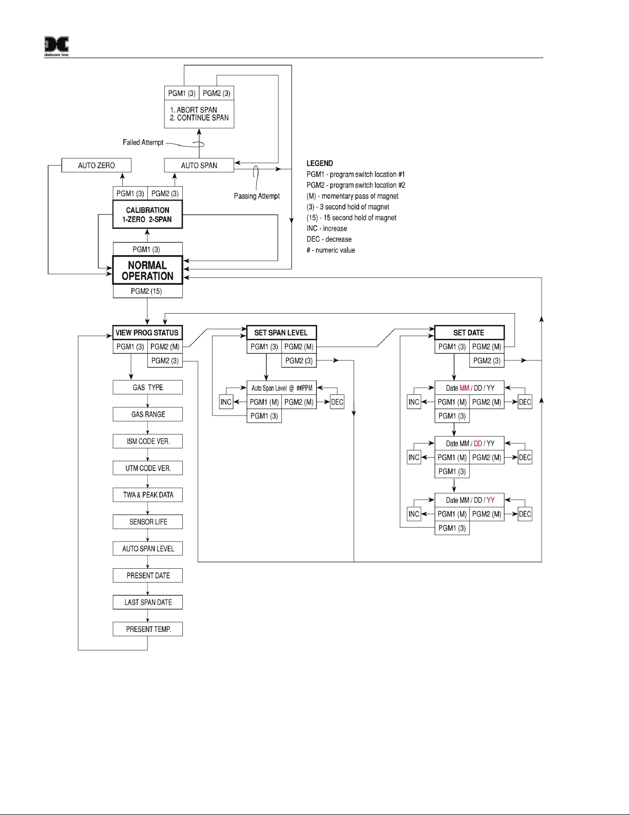
items which include sub-menus as indicated below. (Note: see section 8 for a complete software flow chart.)
01. Normal Operation
a) Current Status
02. Calibration Mode
a) Zero Cal
b) Span Cal
03. Program Mode
a) View Program Status
b) Set Span Level
c) Set Date
3.1 Normal Operation
In normal operation, the display tracks the current status of the sensor and gas concentration and appears as:
“0 PPM xxx” (the “xxx” is the abbreviated gas type, i.e., “0 PPM H2S”) or for oxygen “20.9 % O2”. The mA
current output corresponds to the monitoring level of 0-100% of range = 4-20 mA. If applicable, the second
line of the display will show current “Fault” conditions.
3.2 Calibration Mode
Calibration mode allows for sensor zero and span adjustments. “1-Zero Cal, 2-Span Cal”
Zero Adjustment
Zero is set in ambient air with no target gas present or with zero gas applied to the sensor. “Auto Zero”
For oxygen, zero is performed with 100% nitrogen test gas applied.
Span Adjustment
Span adjustment is performed with a target gas concentration of 50% of range in balance of air or nitrogen.
Span gas concentrations other than 50% of range may be used. Refer to section 3.3 for details. “Auto Span”
For oxygen, s
pan is set in normal ambient air or with test gas containing 20.9% O2 applied to the sensor.
3.3 Program Mode
The program mode provides a program status menu (View Program Status) to check all operational
parameters. It also allows for the adjustment of the auto span gas level setting and the current calendar date.
View Program Status
The view program status scrolls through a menu that displays the following information (the slash means the
data shown is on line two of the display). The information shown is an example of a typical status display.
1. The sensor type. The menu item appears as: “Sensor Type / CO”
2. The sensor range of detection. The menu item appears as: “Sensor Range / 0-100 PPM”
DM-200 Instruction Manual Rev. 2.0 Page 10 of 40
Page 15
Model DM-200
3. The ISM software version number. The menu item appears as: “ISM Code Ver. / 1.10 Apr
2001”
4. The UTM software version number. The menu item appears as: “UTM Code Ver. / 1.10 Apr
2001”
5. The time weighted average and peak data (last 8 hours). The menu item appears as: “TWA: xx
PPM / PK: xx PPM@ –xx Min”
6. The estimated remaining sensor life. The menu item appears as: “Sensor Life / 100%”
7. The calibration span gas level setting. The menu item appears as: “Auto Span Level / 50 PPM”
8. The date. The menu item appears as: “Present Date/ 5/1/01”
9. The last successful span date. The menu item appears as: “Last Span Date / 5/1/01”
10. The temperature. The menu item appears as: “Present Temp / 23°C”
Set Span Level Adjustment
The Span level is adjustable from 10% to 90% of range. The menu item appears as:“Span Gas Value / xx
PPM”
Set Date Adjustment
Set the present date. The menu item appears as: “Date / 05/01/01”
Programming Magnet Operating Instructions
Operator interface to UniTox™ gas detection products is via magnetic switches located behind the UTM
enclosure cover. DO NOT remove the cover to calibrate or change programming parameters. Two switches
labeled “PGM 1” and “PGM 2” allow for complete calibration and programming without removing the
enclosure cover, thereby eliminating the need for area de-classification or the use of hot permits.
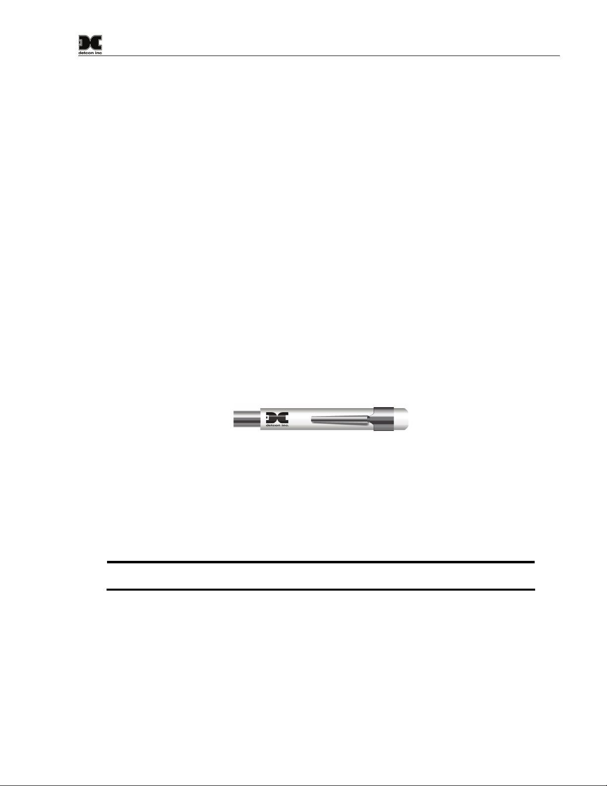
Figure 11 Magnetic Programming Tool
A magnetic programming tool (see figure 5) is used to operate the switches. Switch action is defined as
momentary contact, 3 second hold, and 15 second hold. In momentary contact use, the programming magnet
is waved over a switch location. In 3 second hold, the programming magnet is held in place over a switch
location for 3 or more seconds. In 15 second hold, the programming magnet is held in place over a switch
location for 15 seconds. Three (3) and fifteen (15) second holds are used to enter or exit calibration and
program menus while momentary contact is used to make set-point adjustments. The location of “PGM 1” and
“PGM 2” is shown in Figure 4
NOT
E: If, after entering the calibration or program menus, there is no interaction with the
menu items for more than 30 seconds, the sensor will return to its normal operating condition.
DM-200 Instruction Manual Rev. 2.0 Page 11 of 40
Page 16
Model DM-200
Figure 12 Software Flow Chart
DM-200 Instruction Manual Rev. 2.0 Page 12 of 40
Page 17
Model DM-200
3.4 Calibration - Toxics
3.4.1 Calibration Procedure - Zero
NOTE: Before performing a zero calibration, be sure there is no background gas present or
apply a zero gas standard for 1-2 minutes prior to performing zero calibration.
a) Enter the calibration menu by holding the programming magnet stationary over “PGM 1” (see Figure
4) for 3 seconds until the display
b) Next, enter the Zero Cal menu by holding the magnet stationary over “PGM 1” for 3 seconds until the
display reads: “Auto Zero”, then withdraw the magnet. The sensor has now entered the Auto Zero
mode which lasts for 7 seconds. When it is complete the display will read “Zero Complete” for 2
seconds and then report the date of the last span as a reminder. Following that the display will read
“Return to Normal Operation” for 3 seconds and then Auto Zero is complete. If applicable, remove
gas.
NOTE: If the circuitry is unable to adjust the zero to the proper setting, the sensor will enter a
calibration fault mode which will cause the display to alternate between the sensor’s current
status reading and the calibration fault screen which appears as: “Zero Cal Fault”.
NOTE: Upon entering the calibration menu, the 4-20 mA signal drops to 3.5 mA until the unit
returns to normal operation.
NOTE: When a “Zero Cal Fault” occurs, the sensor microprocessor retains its previous zero
calibration reference.
3.4.2 Calibration Procedure - Span
NOTE: It is best practice to do a Zero Cal just prior to a Span Cal.
Material Requirements
• Detcon PN 327-000000-000 Programming Magnet
• Span gas containing the target gas in air or nitrogen. The target gas concentration is recommended at
50% of range (which is the factory default) at a controlled flow rate of 500 ml/min. Example: for a
Model DM-200-H2S sensor with a range of 0-100 ppm, a test gas of 50 ppm is recommended. For a
sensor with a range of 0-10ppm a test gas of 5 ppm is recommended, etc. Other concentrations can be
used as long as they fall within 10% to 90% of range. See below for details. See section 3.6.1 if you
do n
ot know the sensor target gas or range of detection.
CAUTION: Verification of the correct calibration gas level setting and calibration span gas
concentration is required before “span” calibration. These two numbers must be equal before
proceeding.
Calibration consists of entering the calibration function and following the menu-displayed instructions. The
display will ask for the application of span gas in a specific concentration. This concentration is equal to the
span gas level setting. The factory setting for span gas concentration is typically 50% of range, but may be
different depending on gas availability. For normal calibration, a span gas containing a concentration equal to
50% of range is required. If a span gas containing 50% of range is not available, other concentrations may be
used as long as they fall within 10% to 90% of range. However, any alternate span gas concentration value
must be programmed via the calibration gas level menu before proceeding with span calibration. Follow the
instructions below for span calibration.
reads “1-Zero Cal 2-Span Cal”, and then withdraw the magnet.
DM-200 Instruction Manual Rev. 2.0 Page 13 of 40
Page 18

Model DM-200
a) Verify the current calibration gas level setting as indicated by the programming status menu. To do
this, follow the instructions in Section 10 and make note of the setting found in listing number 7. The
item appears as “Auto Span Level / xx PPM”.
b) If the calibration gas level setting is equal to your calibration span gas concentration, proceed to item
“f”. If not, adjust the calibration gas level setting so that it is equal to your calibration span gas
concentration, as instructed in items “c” through “e”.
c) Enter the programming menu by holding the programming magnet stationary over “PGM 2” for 15
seconds until the display reads “View Program Status”, and then withdraw the magnet. At this point
you can scroll through the programming menu by momentarily waving the programming magnet over
“PGM 1” or “PGM 2”. The menu options are: View Program Status, Set Span Level, and Set Date.
d) From the programming menu scroll to the calibration level listing. The menu item appears as: “Set
Span Level”. Enter the menu by holding the programming magnet stationary over “PGM 1” for 3
seconds until the display reads “Auto Span Level / ##PPM”, then withdraw the magnet. Use the
programming magnet to make an adjustment using “PGM 1” to increase or “PGM 2” to decrease the
display reading until the reading is equal to the desired calibration span gas concentration. To
accept/retain the newly entered value, hold the programming magnet over “PGM1” for 3 seconds.
NOTE: The newly entered span gas value is not saved to permanent memory until a span
calibration is successfully executed with it. New span gas values that are not saved to
permanent memory will be lost when power is lost.
e) Exit back to normal operation by holding the programming magnet over “PGM 2” for 3 seconds, or
automatically return to normal operation in 30 seconds.
f) From the calibration menu “1-Zero Cal 2-Span Cal” (section 3.4.1) proceed into the span adjust
function by holding the programming magnet stationary over “PGM 2” for 3 seconds then withdraw
the programming magnet. At this point the display will ask for the application of the target gas and
concentration. The display reads “Apply xxPPM Span Gas”. The ‘xx’ here will indicate the
concentration requested.
DM-200 Instruction Manual Rev. 2.0 Page 14 of 40
Page 19
Model DM-200
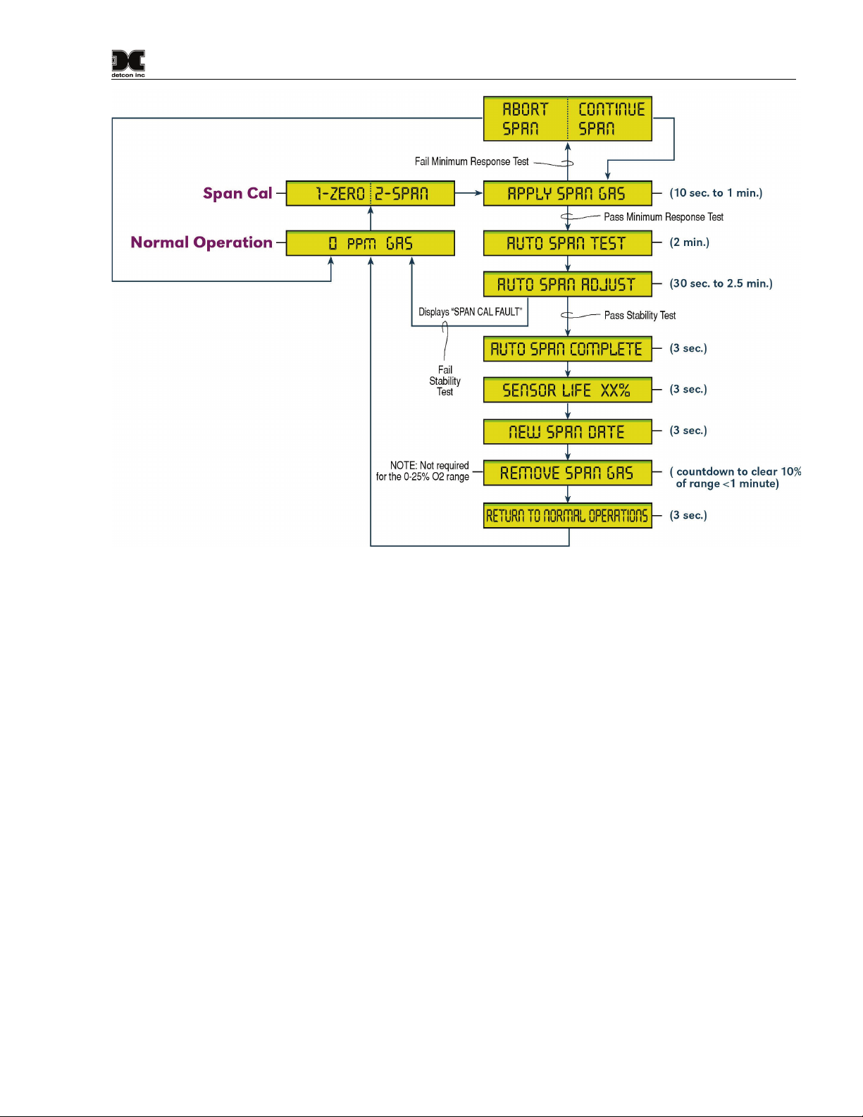
Figure 13 Auto Span Sequence - Toxics
g) Apply the calibration test gas at a flow rate of 500 milliliters per minute. When the sensor response
exceeds 10% of the applied test gas, the display will change to “Auto Span Test” for a period of 2
minutes.
If sensor response does not exceed 10% of applied gas after 1 minute, the menu “1-Abort Span / 2-Continue
Span” appears. This gives the user an opportunity to verify proper span gas delivery and concentration before
continuing forward. If it is desirable to “Abort Span” and try again, then that choice may be exercised.
At two minutes the message will change to “Auto Span Adjust” for an additional 30 seconds. During this
period the sensor will analyze the signal for stability. The criterion for stability is signal drift within ±2% of
full scale in 30 seconds. If met, the message changes to “Auto Span Complete”.
If not met, up to 4 additional 30 second stability check periods are administered. If all 5 stability checks fail,
then the unit returns to Normal Operations with the original Auto Span parameter intact. An alternating
message of “Span Calibration Fault” is displayed to remind the user that a re-calibration is still necessary.
With “Auto Span Complete” achieved, the display now reports the remaining “Sensor Life xx%”, then the
“New Span Date”, and then “Remove Span Gas / xx PPM” which prompts the user to remove the span gas
from the sensor. During “Remove Span Gas / xx PPM”, the sensor recovers toward zero, and when the
signal level falls below 10% of full scale the display changes to “Return to Normal Operation”.
Additional Notes
1. Upon entering the calibration menu, the 4-20 mA signal drops to 3.5 mA and is held at this level until
the unit returns to normal operation.
DM-200 Instruction Manual Rev. 2.0 Page 15 of 40
Page 20

Model DM-200
2. If during calibration the sensor circuitry is unable to attain the proper adjustment for span, the sensor
will enter into the “Span Calibration Fault” mode which will cause the display to alternate between the
sensor’s current status reading and the calibration fault screen which appears as: “Span Cal Fault”.
If this occurs you may attempt to recalibrate by entering the calibration menu as described in section
3.4.1. If the sensor fails again, defer to technical trouble shooting.
NOTE: The newly entered span gas value is not saved to permanent memory until a span
calibration is successfully executed with it. New span gas values that are not saved to
permanent memory will be lost when power is lost.
3.4.3 Calibration Frequency
In most applications, monthly to quarterly calibration intervals will assure reliable detection. However,
industrial environments differ. Upon initial installation and commissioning, close frequency tests should be
performed, weekly to monthly. Test results should be recorded and reviewed to determine a suitable
calibration interval.
3.5 Calibration – Oxygen
3.5.1 O2 Calibration Procedure - Span
Material Requirements:
• Detcon PN 327-000000-000 Programming Magnet
• 0-25% O2 Range: Span gas containing 20.9% O2 in nitrogen at a controlled flow rate of 500 ml/min.
Ambient air (no calibration adapter) may be used directly as long as it is absolutely known that 20.9%
O2 level exists at the time of calibration.
• Other Ranges: Span gas at 50% of range.
CAUTION: Verification of the correct calibration gas level setting and calibration span gas
concentration is required before “span” calibration. These two numbers must be equal before
proceeding.
Calibration consists of entering the calibration function and following the menu-displayed instructions. The
display will ask for the application of span gas in a specific concentration. This concentration is equal to the
span gas level setting. The factory default setting for span gas concentration is typically 50% of range but for
the 0-25% O2 range it is set to 20.9%. If a span gas containing 50% of range is not available, other
concentrations may be used as long as they fall within 10% to 90% of range. However, any alternate span gas
concentration value must be programmed via the calibration gas level menu before proceeding with span
calibration. Follow the instructions below for span calibration.
a) Verify the current calibration gas level setting as indicated by the programming status menu. Refer
Section 3.6.1 and make note of the setting found in item number 7. The item appears as “Auto Span
Level / xx PPM/%”.
b) If the calibration gas level setting is equal to your calibration span gas concentration, proceed to item
“f”. If not, adjust the calibration gas level setting so that it is equal to your calibration span gas
concentration, as instructed in items “c” through “e”.
c) Enter the programming menu by holding the programming magnet stationary over “PGM 2” for 15
seconds until the display reads “View Program Status”, and then withdraw the magnet. At this point
you can scroll through the programming menu by momentarily waving the programming magnet over
“PGM 1” or “PGM 2”. The menu options are: View Program Status, Set Span Level, and Set Date.
DM-200 Instruction Manual Rev. 2.0 Page 16 of 40
Page 21
Model DM-200
d) From the programming menu scroll to the calibration level listing. The menu item appears as: “Set
Span Level”. Enter the menu by holding the programming magnet stationary over “PGM 1” for 3
seconds until the display reads “Auto Span Level / ##PPM/%”, then withdraw the magnet. Use the
programming magnet to make an adjustment using “PGM 1” to increase or “PGM 2” to decrease the
display reading until the reading is equal to the desired calibration span gas concentration. To
accept/retain the newly entered value, hold the programming magnet over “PGM1” for 3 seconds.
e) Exit back to normal operation by holding the programming magnet over “PGM 2” for 3 seconds, or
automatically return to normal operation in 30 seconds.
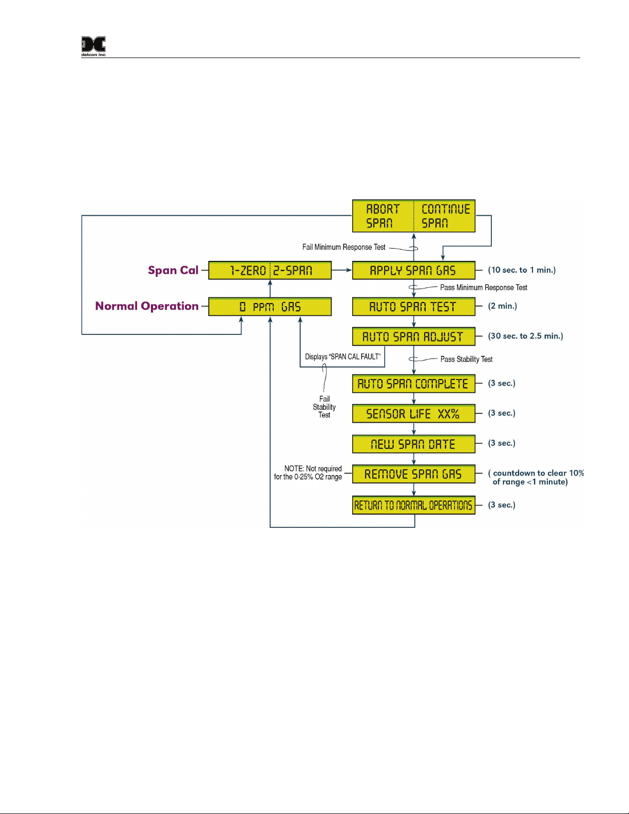
Figure 14 Auto Span Sequence - Oxygen
f) From the calibration menu “1-Zero Cal 2-Span Cal” (section 3.4.1) proceed into the span adjust
function
by holding the programming magnet stationary over “PGM 2” for 3 seconds then withdraw
the programming magnet. At this point the display will ask for the application of the target gas and
concentration. The display reads “Apply xxPPM/% Span Gas”. The ‘xx’ here will indicate the
concentration requested.
g) Apply the calibration test gas at a flow rate of 200 milliliters per minute. When the sensor response
exceeds 10% of the applied test gas, the display will change to “Auto Span Test” for a period of 2
minutes.
If sensor response does not exceed 10% of applied gas after 1 minute, the menu “1-Abort Span / 2-Continue
Span” appears. This gives the user an opportunity to verify proper span gas delivery and concentration before
continuing forward. If it is desirable to “Abort Span” and try again, then that choice may be exercised.
DM-200 Instruction Manual Rev. 2.0 Page 17 of 40
Page 22

Model DM-200
At two minutes the message will change to “Auto Span Adjust” for an additional 30 seconds. During this
period the sensor will analyze the signal for stability. The criteria for stability is signal drift within ±2% of full
scale in 30 seconds. If met, the message changes to “Auto Span Complete”.
If not met, up to 4 additional 30 second stability check periods are administered. If all 5 stability checks fail,
then the unit returns to Normal Operations with the original Auto Span parameter intact. An alternating
message of “Span Calibration Fault” is displayed to remind the user that a re-calibration is still necessary.
With “Auto Span Complete” achieved, the display now reports the remaining “Sensor Life xx%”, then the
“New Span Date”, and then “Remove Span Gas / xx PPM/%” which prompts the user to remove the span
gas from the sensor. This is not necessary for the 0-25% O2 range if spanning at 20.9% level. During
“Remove Span Gas / xx PPM/%”, the sensor recovers toward zero, and when the signal level falls below
10% of full scale the display changes to “Return to Normal Operation”.
3.5.2 O2 Calibration Procedure - Zero
Material Requirements
• Detcon PN 327-000000-000 Programming Magnet
• Oxygen free gas standard such as 100% N
• Detcon PN 943-000000-000 Wind Guard for Splashguard
a) Apply an oxygen free gas standard for 2 minutes using the splashguard calibration port with wind
guard in place.
b) Enter the calibration menu by holding the programming magnet stationary over “PGM 1” (refer Figure
4 ) for 3
seconds until the display reads “1-Zero Cal 2-Span Cal”, and then withdraw the magnet.
c) Enter the Zero Cal menu by holding the magnet stationary over “PGM 1” for 3 seconds until the
display reads: “Auto Zero”, then withdraw the magnet. The sensor has now entered the Auto Zero
mode which lasts for 7 seconds. When it is complete the display will read “Zero Complete” for 2
seconds and then report the date of the last span as a reminder. Following that the display will read
“Return to Normal Operation” for 3 seconds and then Auto Zero is complete. Remove the test gas.
NOTE 1: If the circuitry is unable to adjust the zero to the proper setting, the sensor will enter
a calibration fault mode which will cause the display to alternate between the sensor’s current
status reading and the calibration fault screen which appears as: “Zero Cal Fault”.
NOTE 2: Upon entering the calibration menu, the 4-20 mA signal drops to 3.5 mA until the
unit returns to normal operation
NOTE 3: When a “Zero Cal Fault” occurs, the sensor microprocessor retains its previous zero
calibration reference.
2
3.6 Status of Programming and ISM Parameters
The programming menu has a “View Program Status” listing that allows the operator to view the sensor type,
range, software version numbers, time weighted average (TWA) and peak reading in last 8 hours, remaining
sensor life, auto span level, present date, last span date, and present temperature. The programming menu also
allows the changing of the span gas level setting (see section 9.2), and calendar date.
DM-200 Instruction Manual Rev. 2.0 Page 18 of 40
Page 23

Model DM-200
3.6.1 View Program Status
The following procedure is used to view the programming status of the sensor:
b) Enter the programming menu by holding the programming magnet stationary over “PGM 2” for 15
seconds until the display reads “VIEW PROG STATUS”, and then withdraw the magnet. At this
point you can scroll through the programming menu by momentarily waving the programming magnet
over “PGM 1” or “PGM 2”. The menu options are: View Program Status, Set Span Level, and Set
Date.
c) Scroll to the “VIEW PROG STATUS” listing and then hold the programming magnet over “PGM 1”
for 3 seconds. The menu will then automatically scroll, at 3 second intervals, through the following
information before returning back to the “VIEW PROG STATUS” listing.
1. The sensor type. The menu item appears as: “Sensor Type / CO”
2. The sensor range of detection. The menu item appears as: “Sensor Range / 0-100 PPM”
3. The ISM software version number. The menu item appears as: “ISM Code Ver. / 1.10 Apr
2001”
4. The UTM software version number. The menu item appears as: “UTM Code Ver. / 1.10 Apr
2001”
5. The time weighted average and peak. The menu item appears as: “TWA: xx PPM / PK: xx
PPM@ –xx Min”
6. The estimated remaining sensor life. The menu item appears as: “Sensor Life / 100%”
7. The calibration span gas level setting. The menu item appears as: “Auto Span Level / 50 PPM”
8. The date. The menu item appears as: “Present Date/ 5/1/01”
9. The last successful span date. The menu item appears as: “Last Span Date / 5/1/01”
10. The temperature. The menu item appears as: “Present Temp / 23°C”
d) Exit back to normal operations by holding the programming magnet over “PGM 2” for 3 seconds, or
automatically return to normal operation in 30 seconds.
3.6.2 Set Date
The following procedure is used to set the present calendar date:
a) Enter the programming menu by holding the programming magnet stationary over “PGM 2” for 15
seconds until the display reads “View Program Status”, and then withdraw the magnet. At this point
you can scroll through the programming menu by momentarily waving the programming magnet over
“PGM 1” or “PGM 2”. The menu options are: View Program Status, Set Span Level, and Set Date.
b) From the programming menu scroll to the “Set Date” listing. Enter the menu by holding the
programming magnet stationary over “PGM 1” for 3 seconds until the display reads “Set Date /
xx/xx/xx”, and then withdraw the magnet. The first set of numbers (month) will flash on and off
indicating they are ready for adjustment. Use the programming magnet to make an adjustment to
“PGM 1” to increase or “PGM 2” to decrease the display reading until the reading is equal to the
desired month.
c) Next, advance to the second set of numbers (the day) by holding the programming magnet stationary
over “PGM 1” for 3 seconds until the month set flashes on and off indicating they are ready for
adjustment. Use the programming magnet to make an adjustment to “PGM 1” to increase or “PGM 2”
to decrease the display reading until the reading is equal to the desired day.
d) Next, advance to the third set of numbers (the year) by holding the programming magnet stationary
over “PGM 1” for 3 seconds until the year set flashes on and off indicating they are ready for
DM-200 Instruction Manual Rev. 2.0 Page 19 of 40
Page 24

Model DM-200
adjustment. Use the programming magnet to make an adjustment to “PGM 1” to increase or “PGM 2”
to decrease the display reading until the reading is equal to the desired year.
To retain the newly entered value, hold the programming magnet over “PGM1” for 3 seconds.
e) Exit back to normal operation by holding the programming magnet over “PGM 2” for 3 seconds, or
automatically return to normal operation in 30 seconds.
3.7 Program Features
Detcon UniTox™ toxic gas sensors incorporate a comprehensive program to accommodate easy operator
interface and fail-safe operation. Program features are detailed in this section. Each sensor is factory tested,
programmed, and calibrated prior to shipment.
Sensor Life
The sensor life feature is a reference based on signal output from the sensor cell. When a sensor life of 25% or
less remains the sensor cell should be replaced within a reasonable maintenance schedule.
Data Logging
The data logging feature records the most recent 8 hours of data: time-weighted average (TWA) and peak (PK)
reading. The menu item appears as “TWA: xx PPM / PK: xx PPM@ xx Min”. TWA is a rolling 8 hour
average updated at 30 minute intervals. The peak (PK) reading is the instantaneous peak reading recorded in
the last 8 hours and the “@ –xx Min” represents the “number of minutes ago” that the peak reading took place.
For example: “PK: 33 PPM@ –360 Min” explains that a peak reading of 33 ppm took place 6 hours (360
minutes) ago.
NOTE: For oxygen sensing, the Peak (PK) reading is the lowest reading recorded in the last 8 hours
Over Range
When the sensor detects gas greater than 100% of range, it will display the highest reading of its range and an
output of 20 mA.
Under Range Fault
If the sensor should drift below a zero baseline of –10% of range, the display will indicate a fault: “Sensor
Fault” and report an output of 3.5 mA. This is typically fixed by performing another zero cal.
Span Calibration Fault
If during calibration the sensor circuitry is unable to attain the proper adjustment for span, the sensor will enter
into the span calibration fault mode and cause the display to alternate between the sensor’s normal operation
reading and the calibration fault screen which appears as: “Span Cal Fault”. The previous calibration
settings will remain saved in memory.
Zero Calibration Fault
If during calibration the sensor circuitry is unable to attain the proper adjustment for zero, the sensor will enter
into zero calibration mode and cause the display to alternate between the sensor’s normal operation reading
and the calibration fault screen which appears as: “Zero Cal Fault”. The previous calibration settings will
remain saved in memory.
DM-200 Instruction Manual Rev. 2.0 Page 20 of 40
Page 25

Model DM-200
Missing Sensor
If the ISM is missing or not connected properly, the UTM will report “Missing Sensor” and an output of 1.0
mA will be set.
Memory Fault
If new data points cannot successfully be retrieved from memory the display will indicate: “Memory Fault”.
Comm Error
If the ISM and UTM are not communicating properly, then the UTM will report “Comm Error”.
4. Service and Maintenance
4.1 Exchanging the ISM
A key feature of the UniTox™ product is its complete universality (exchangeability) between any combination
of ISM and UTM. The ISM carries all necessary identification and parameter data stored in permanent
memory, which allows for any ISM to instantly begin seamless operation with any UTM.
4.1.1 Physical Exchange
In order to remove an ISM, the user should twist the retaining collar in a counter clockwise direction. When
the threads are cleared, the ISM should be pulled straight out. To reinstall the ISM, first view the mating gold
pin pattern until proper alignment is achieved. Then press in the ISM until mechanical surfaces touch.
Finally, move the retaining collar up and thread clockwise until snug.
NOTE: Remember to twist the retaining collar tight after successful ISM/UTM
communication is established. The collar should tighten snugly up to the mating surface in
order to create a water tight seal. Never grab the ISM main housing and attempt to twist. This
may damage the gold pin connections.
4.1.2 Establishing Communication
The UTM will display "Missing Sensor" during time when the ISM is not connected. When an ISM is
disconnected from a UTM, the end-user must wait approximately 7 seconds before another ISM can be
plugged into the UTM. This 7 second period is the time required by the UTM to reach the "ready-to-receive"
state.
After plugging an ISM into the UTM, within 1-3 seconds the ISM identification/parameter information will be
displayed and at the conclusion of the data string a "Returning to Normal Operation" message will be
shown. If for some reason the ISM identification/parameter information does not come up after 10 seconds,
then unplug the ISM and repeat the process again after 10 seconds.
4.1.3 Maintaining "Biased" ISM’s using the Battery Back-up Module (Optional)
When and How to Use
Some electrochemical sensors are biased with an excitation voltage. When power to the ISM is lost, this bias
voltage slowly decays. When power is restored after long periods (multiple hours) of being un-powered, a
surge in sensor output takes place and a long and slow re-establishing of the sensor’s zero baseline takes place.
This re-stabilization time may range from 1 hour to 24 hours depending on the type of sensor and range of
operation. The sensor types that this applies to are the following: HCl, NO, plus all the VOC sensors, C2H30,
DM-200 Instruction Manual Rev. 2.0 Page 21 of 40
Page 26
Model DM-200
C2H2, C3H3N, C4H6, CS2, COS, C2H6S, C3H5OCL, C2H5OH, C2H4, C2H4O, CH2O, CH3OH, C4H4S,
C4H6O2, C6H5CH3 and C2H3CL.
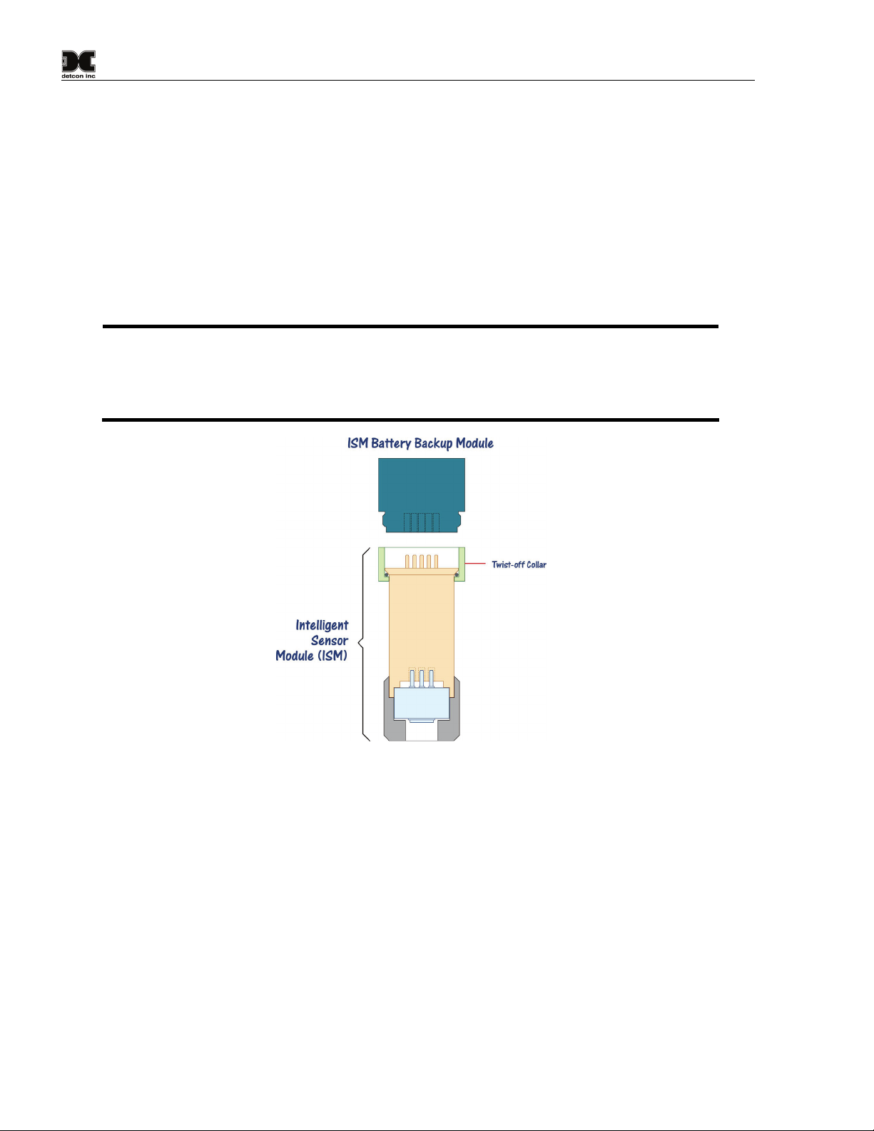
The Battery Back-up Module (Optional) has been designed to eliminate re-stabilization down-time by keeping
the ISM completely powered and in a 100% ready state. The Battery Back-up module has a service life of 1.5
years in continuous use.
It is recommended that the "biased" ISM types remain connected to the Battery Back-up Module when not in
use for long periods of time. While transporting a calibrated ISM from the office to the field, it is
recommended to use the Battery Back-up Module to eliminate re-stabilization time. However, for short
durations of 5-10 minutes or less in the un-powered state, it is not necessary to use the Battery Back-up
Module.
NOTE: The Battery Back-up Module can be used to warm-up a "biased" ISM that has been
un-powered. Plugging the ISM into the Battery Back-up Module for 24 hours prior to
calibration is recommended. The ISM plugs into the Battery Back-up Module in the same way
it plugs into the UTM. The gold pin pattern is aligned, pressed together, and the retaining
collar is tightened. Reverse instructions to remove.
Figure 15 ISM Battery Backup Module
4.2 Exchanging Electrochemical Sensors
If an electrochemical sensor exchange is necessary, due to poor sensor performance (See Trouble Shooting
Guide for details). The following procedure should be used.
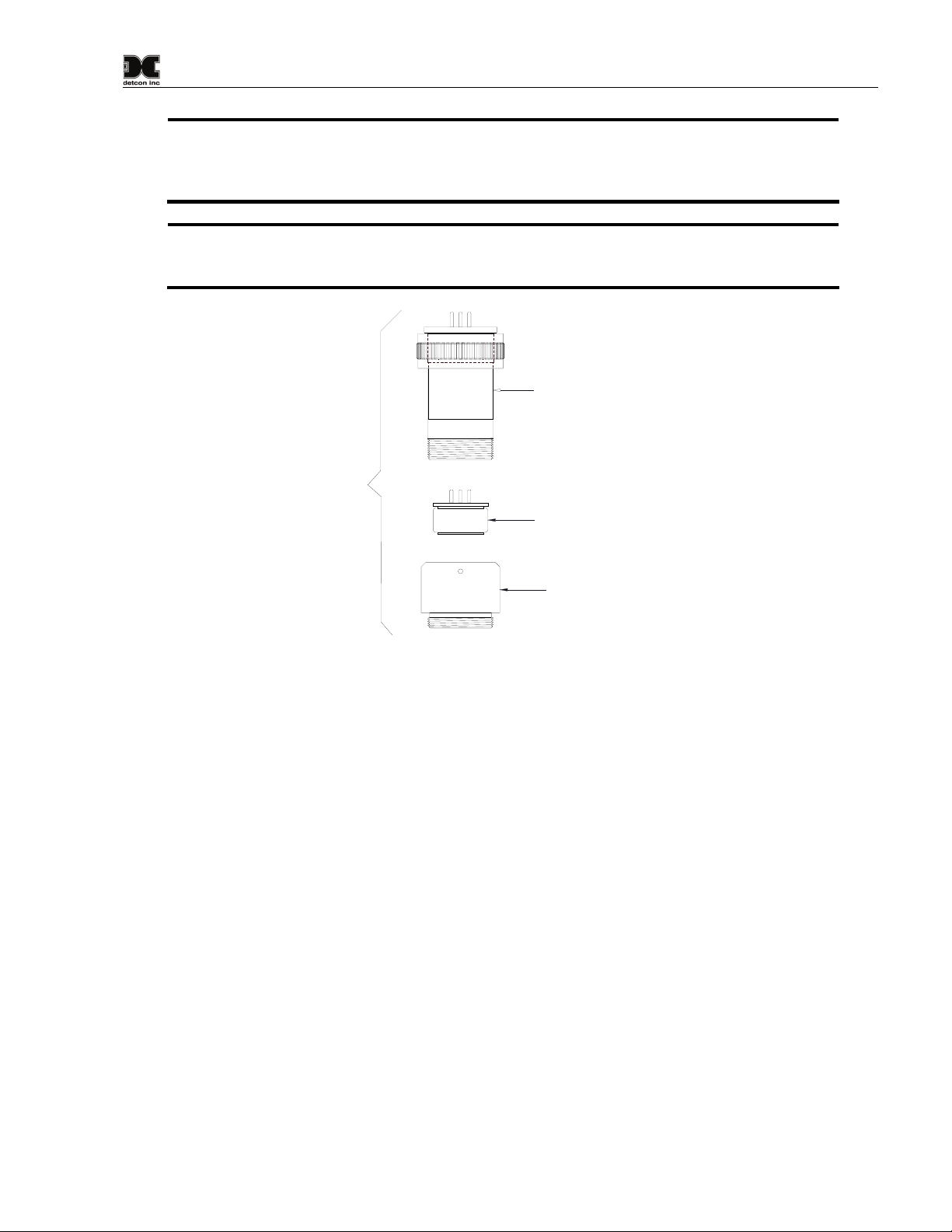
Remove the ISM from UTM per Section 4.1
Loosen the l
housing, twist the sensor splashguard adapter counter-clockwise to remove. It may be secured very tight, so
some firm twisting will be required. Once removed the electrochemical sensor is exposed. To remove it, grab
the electrochemical sensor body and pull straight out.
Take your replacement electrochemical sensor and carefully verify that it is identical in gas type and part
number. This information is listed on the label of the electrochemical sensor. You may refer to Table 3 to
verify
the correct part number of replacement electrochemical sensors.
DM-200 Instruction Manual Rev. 2.0 Page 22 of 40
ocking setscrew in splashguard adapter. While firmly holding the center of the ISM main
Page 27
Model DM-200
NOTE: This is critical because each ISM is pre-set to accept a specific electrochemical sensor.
Take your replacement sensor and observe the gold pin mating pattern. Once aligned, press the
sensor into the sockets and replace the sensor rain cover with a firm twist to create the water
tight seal.
NOTE: If the sensor splashguard adapter cannot be removed, it maybe locked down by the
setscrew or may have been intentionally, permanently bonded in place. In this case, the entire
ISM must be replaced.
Intelligent
Sensor
Housing
(With support
Electronics)
Intelligent
Sensor
Module
(ISM)
Electrochemical cell
Grasp and pull down to remove
Splashguard adapter
Twist counter-clockwise
to remove
Figure 16 Sensor Cell Replacement
4.3 Display Contrast Adjust
Detcon UniTox™ sensors feature a 2-line, 16-character liquid crystal display. Like most LCDs, character
contrast can be affected by viewing angle and temperature. Temperature compensation circuitry included in
the UniTox™ design will compensate for this characteristic; however temperature or operating voltage
extremes may still cause a shift in the contrast. Display contrast can be adjusted by the user if necessary.
To adjust the display contrast, remove the enclosure cover, remove transmitter, and use a small screwdriver to
turn the blue contrast potentiometer adjust screw located on the side of the UTM circuit board (refer Figure 5).
Adjust per pr
Replace enclosure cover.
eference. The adjustment location is marked “CONTRAST”. Secure transmitter in condulet.
DM-200 Instruction Manual Rev. 2.0 Page 23 of 40
Page 28

Model DM-200
5. Trouble Shooting Guide
"Missing Sensor" Message
Probable Cause: ISM not being registered by UTM.
1. Reinstall ISM after waiting 10 seconds.
2. Re-power UniTox sensor.
Upscale reading (for > 30 minutes) after ISM connection
Probable Cause: Biased ISM type re-stabilizing.
1. Wait 8 hours minimum.
2. Use Battery Back-up Module to prevent this condition.
"Comm Error" Message
Probable Causes: Faulty wiring/connection, UTM or ISM microprocessor failure.
1. Re-Install ISM.
2. Swap ISM and UTM with another functional pair to determine if ISM or UTM is the problem.
No LCD or 4-20 mA signal activity with power applied
Probable Causes: Blown input fuse, Insufficient Operating Voltage, Mis-wired connection.
1. Check/Replace Fuse.
2. Check for correct polarity and verify Operating voltage at the UTM input terminals.
3. Check status of external field wire I.S. Barrier.
4. Replace UTM with functional UTM.
Noise Spikes or Oscillation on the 4~20mA signal
1. Contact Detcon to report incidence.
2. Install 150µF capacitor across the terminating load resistor at the controller (i.e. install between DC
common and mA input).
LCD not Easily Readable
1. Adjust contrast pot (see section 14).
Erratic Sensor Behavior – False/Fault Alarms
Probable Causes: Wet/Intermittent terminals, RFI Interference, Bad Electrochemical Sensor, Target or Crossinterfering Gases being detected.
1. Check that ISM collar and splashguard adapter are firmly seated and terminals are not wet.
2. RFI- Use shielded cabling.
3. Re-calibrate sensor and make sure it calibrates successfully and Sensor Life is acceptable.
4. Make sure alarms are not being caused by real gas clouds or cross-interfering gases.
"Span Cal Fault" Message
DM-200 Instruction Manual Rev. 2.0 Page 24 of 40
Page 29

Model DM-200
Probable Causes: Incorrect cal gas delivery, Bad calibration gas, Failing Electrochemical sensor, Inadequate
wait time, Incorrect Cal gas value.
1. Verify that existing Sensor Life% value is not < 25%.
2. Verify that the correct span gas value is entered in the program.
3. Determine if failing Auto Span is due to inadequate signal or inadequate stability.
4. Check cal gas flow, type, concentration, and expiration date (validate cal gas with pull tube).
5. If failing AutoSpan stability test, apply cal gas for 3-5 minutes before executing AutoSpan.
6. If failing AutoSpan signal test, change-out electrochemical sensor and retry AutoSpan.
Clearing "Span Cal" Fault Message
1. This message can be cleared by performing either a successful AutoSpan or AutoZero.
"Zero Cal Fault" Message
Probable Cause: Zero cal during High Exposure
1. Verify there is no target gas when doing a zero cal.
2. Use “Zero Air” if necessary.
3. Recalibrate zero after 5 minutes to clear message.
"Sensor Fault" Message
Probable Cause: Zero baseline has drifted negative, Excessive temperature drift.
1. Re-Calibrate Zero.
2. If "Sensor Fault" is intermittent and correlates with temperature – Contact Detcon.
4-20 mA not matching LCD display
Probable Causes: Various
1. Verify adequate operating voltage (> 11.5 VDC).
2. Reads 1.1 mA with "Missing Sensor" - unplug and replug ISM, and/or un-power and re-power unit.
3. Reads 3.5 mA – Unit out of Normal Operation, user must clear out of user interface software.
4. Reads > 0.2 mA in accurately – 4-20 mA should be recalibrated, Contact Detcon for procedure.
"Memory Error" Message
Probable Cause: Faulty memory chip.
1. Exchange UTM and ISM with functioning UTM and ISM and determine which is faulty.
DM-200 Instruction Manual Rev. 2.0 Page 25 of 40
Page 30

Model DM-200
6. Customer Support and Service Policy
Detcon, Inc., as manufacturer, warrants under intended normal use each new UniTox™ UTM control circuit
and ISM control circuit to be free from defects in material and workmanship for a period of one year from the
date of shipment to the original purchaser. Detcon, Inc., further provides for a five year fixed fee service
policy wherein any failed UTM or ISM shall be repaired or replaced as is deemed necessary by Detcon, Inc.,
for a fixed fee of $75.00. The fixed fee service policy shall affect any factory repair for the period following
the one year warranty and shall end five years after the date of shipment to the original purchaser. All
warranties and service policies are FOB the Detcon facility located in The Woodlands, Texas.
7. Warranty
Detcon, Inc., as manufacturer, warrants each new electrochemical toxic gas plug-in sensor cell, for a specified
period (refer Section Error! Reference source not found.) under the conditions described as follows: The
warranty period begins on the date of shipment to the original purchaser and ends after the specified period as
listed in Table 3 in Section Error! Refe
defects in material and workmanship. Should any sensor cell fail to perform in accordance with published
specifications within the warranty period, return the defective part to Detcon, Inc., 3200 A-1 Research Forest
Dr., The Woodlands, Texas 77381, for necessary repairs or replacement.
rence source not found.. The sensor cell is warranted to be free from
DM-200 Instruction Manual Rev. 2.0 Page 26 of 40
Page 31
Model DM-200
8. Spare Parts
Part Number
922-000000-000 200 Universal Xmtr Module
600-003097-000 Model DM-200 SS Splash Guard Adapter
370-XXXX00-XXX Replacement Plug-in toxic gas sensor (Refer to Table 3)
392-XXXX0S-XXX Replacement ISM Modules with Sensor Cell (Refer to Table 6)
613-120000-700 Sensor Splashguard with integral Cal Port
327-000000-000 Programming Magnet
960-202200-000 Condensation prevention packet (for J-Box replace annually)
360-000001-00 UniTox Battery Backup Module
943-050000-132 Span Gas Kit: Includes calibration adapter, span gas humidifier,
943-050000-HRG Highly Reactive Gas Span Gas Kit (Used for NH3, Cl2, HCl, HBr, etc.)
See Detcon Span Gasses
943-05AM00-000 500 cc/min Fixed Flow Regulator for span gas bottle
943-000000-000 Wind Guard for Splashguard
Recommend Spare Parts for 2 Years
922-000000-000 200 Universal Xmtr Module
600-003215-000 Splash Guard Adapter
370-XXXX00-XXX Replacement Plug-in toxic gas sensor (Refer to Table 3)
392-XXXX0S-XXX Replacement ISM Modules with Sensor Cell (Refer to Table 6)
960-202200-000 Condensation prevention packet (for J-Box. Replace annually)
Spare Parts
Sensor Accessories
Calibration Accessories
500cc/min fixed flow regulator, and carrying case. (Not including
gas).
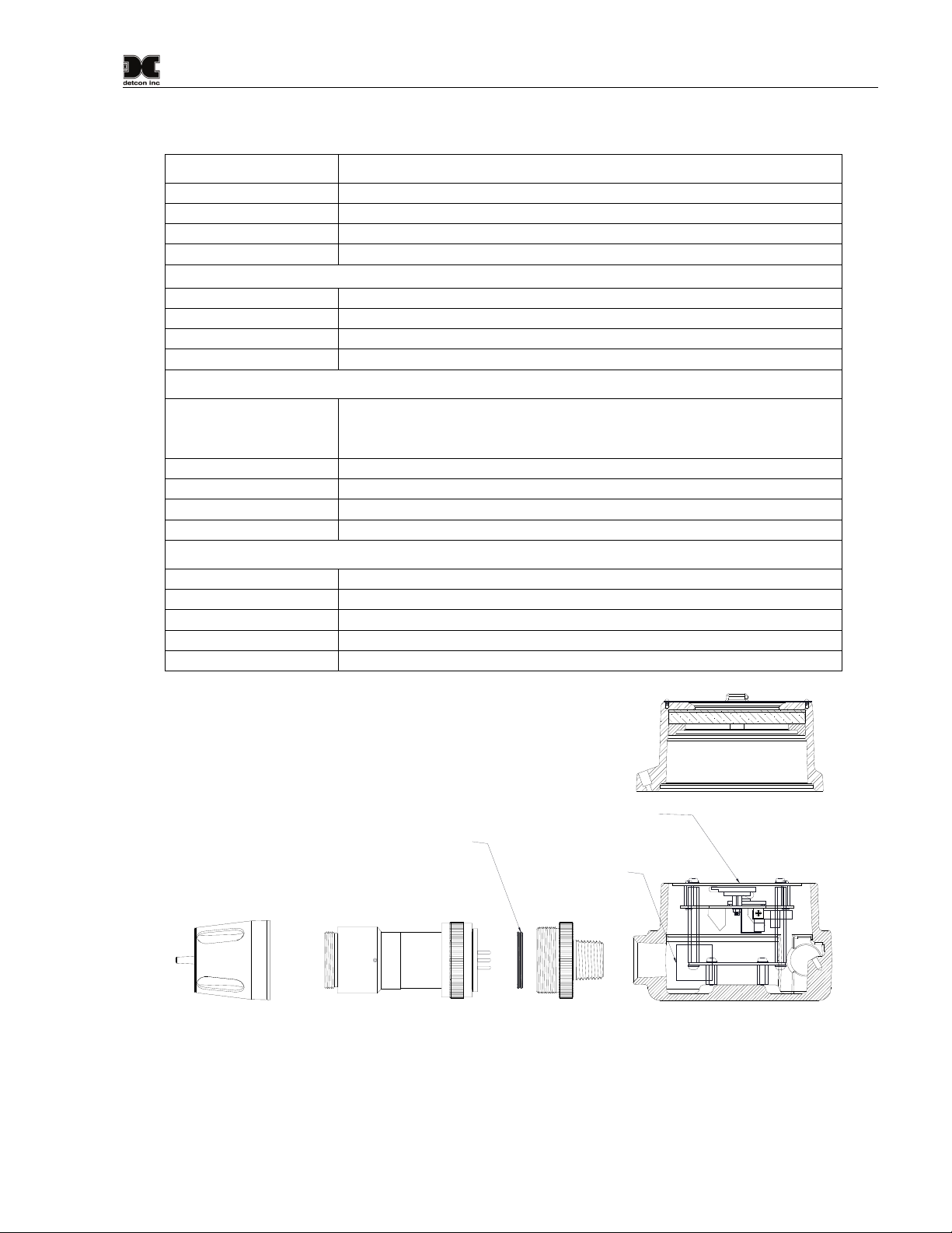
Enclosure Cover
with Window
DM-200 Universal
Transmitter Module
P/N 922-000000-000
Packet
P/N 960-202200-000
P/N 602-002367-000
Splash Guard Assembly
P/N 613-120000-700
Condensation Prevention
Packet
P/N 960-202200-000
Intigent Sensor Module
P/N 392-XXXX0S-XXX
Figure 17 Spare parts Breakaway
Condensation Prevention
Connector Base Assembly
Humidisorb packets eliminate condensation from forming in the condulet enclosure thus preventing problems
such as corrosion and stray signal drift. Use of the Humidisorb packet greatly extends the service and
problem-free operating life of the gas sensor in both tropical and cold weather extremes. Although the
Humidisorb packet is designed for continuous use, it should be replaced on an annual basis for optimal
performance.
DM-200 Instruction Manual Rev. 2.0 Page 27 of 40
Page 32

Model DM-200
Table 2 Intelligent Sensor Module Replacement assembly
Model Number Gas Name Intelligent Sensor Module with Cell (ISM)
DM-200-C2H3O Acetyldehyde 392-12EA0S-Range
DM-200-C2H2 Acetylene 392-12EG0S-Range
DM-200-C3H3N Acrylonitrile 392-12EM0S-Range
DM-200-NH3 (-20°C) Ammonia 392-17170S-Range
DM-201-NH3 (-40°C) Ammonia 392-15150S-Range
DM-202-NH3 (CE) Ammonia 392-50500S-Range
DM-200-AsH3 Arsine 392-19190S-Range
DM-200-Br2 Bromine 392-74750S-Range
DM-200-C4H6 Butadiene 392-12EB0S-Range
DM-200-CS2 Carbon Disulfide 392-12EH0S-Range
DM-200-CO Carbon Monoxide 392-44440S-Range
DM-200-COS Carbonyl Sulfide 392-12EN0S-Range
DM-200-CL2 Chlorine 392-74740S-Range
DM-200-CLO2 (>10ppm) Chlorine Dioxide 392-74760S-Range
DM-200-CLO2 (≤10ppm) Chlorine Dioxide 392-05050S-Range
DM-200-B2H6 Diborane 392-19210S-Range
DM-200-C2H6S Dimethyl Sulfide 392-12EC0S-Range
DM-200-C3H5OCL Epichlorohydrin 392-12EI0S-Range
DM-200-C2H5OH Ethanol 392-12EO0S-Range
DM-200-C2H5SH Ethyl Mercaptan 392-24EZ0S-Range
DM-200-C2H4 Ethylene 392-12ED0S-Range
DM-200-C2H4O Ethylene Oxide 392-12EJ0S-Range
DM-200-F2 Fluorine 392-27270S-Range
DM-200-CH2O Formaldehyde 392-12EP0S-Range
DM-200-GeH4 Germane 392-23250S-Range
DM-200-N2H4 Hydrazine 392-26260S-Range
DM-200-H2 (≤1000ppm) Hydrogen 392-84840S-Range
DM-201-H2 (1-4%LEL) Hydrogen 392-05050S-Range
DM-202-H2 (1K-10Kppm) Hydrogen 392-07070S-Range
DM-200-HBr Hydrogen Bromide 392-09080S-Range
DM-200-HCL Hydrogen Chloride 392-09090S-Range
DM-200-HCN Hydrogen Cyanide 392-13130S-Range
DM-200-HF Hydrogen Fluoride 392-33330S-Range
DM-200-H2S Hydrogen Sulfide 392-24240S-Range
DM-200-CH3OH Methanol 392-12EE0S-Range
DM-200-CH3SH Methyl Mercaptan 392-24EK0S-Range
DM-200-NO Nitric Oxide 392-94940S-Range
DM-200-NO2 Nitrogen Dioxide 392-64640S-Range
DM-200-O2 Oxygen 392-34340S-Range
DM-200-O3 Ozone 392-39390S-Range
DM-200-COCL2 Phosgene 392-41410S-Range
DM-200-PH3 Phosphine 392-19200S-Range
DM-200-SiH4 Silane 392-23230S-Range
DM-200-SO2 Sulfur Dioxide 392-55550S-Range
DM-200-C4H8S Tetrahydrothiophene 392-43430S-Range
DM-200-C4H4S Thiophane 392-12EQ0S-Range
DM-200-C6H5CH3 Toluene 392-12ER0S-Range
DM-200-C4H6O2 Vinyl Acetate 392-12EF0S-Range
DM-200-C2H3CL Vinyl Chloride 392-12EL0S-Range
1
Specify Range: 0-1ppm = 001; 0-10ppm = 010; 0-25ppm = 025; 0-100ppm = 100; 0-1000ppm = 01K etc. Part numbers for replacement assemblies
listed in table include sensor cell as part of ISM package. If replacement of ISM only is required, Contact Detcon Sales or Service department for part
number needed.
DM-200 Instruction Manual Rev. 2.0 Page 28 of 40
1
Page 33

Model DM-200
9. Specifications
Sensor Type: Continuous diffusion/adsorption type
3-Electrode Electrochemical Sensor (2-Electrode for O
Plug-in Replaceable Type
Sensor Life: 2 years typical
Measuring Ranges: 0-1 ppm up to 0-10,000 ppm (Toxic Gasses)
0-1% up to 0-25% volume (O
)
2
Accuracy/ Repeatability: ±2% of full-range (Toxic Gasses)
±1% of full-range (O
)
2
Response Time: T90 < 30 seconds typical (See Sensor Table)
Environmental Specifications
Operating Temperature: -40°C to +50°C typical (See Table 3)
Storage Temperature: -40°C to +50°C typical (See Table 3)
Operating Humidity: 10-95% RH Continuous Duty (See Table 3)
0-100% RH Short-Term Duration Only
Operating Pressure: Ambient ±10%
Electrical Specifications
)
2
Input Voltage: 11.5-30 VDC
Power Consumption
Normal operation = 4 mA (0.1 watts @ 24VDC);
Maximum = 20 mA (0.5 watts @ 24VDC)
RFI/EMI Protection: Complies with EN61326
Analog Output: Linear 4-20mA DC current
1000 ohms maximum loop load @ 24VDC
3.5 mA All Fault Diagnostics
3.5 mA In-Calibration
4-20 mA 0-100% full-scale
Mechanical Specifications
Length: 12.5 inches (317.5 mm), Includes Splashguard
Width: 6.0 inches (152.5 mm)
Weight: 5.6 lbs (2.5 Kg)
Mechanical Connection: ¾” Male NPT threaded connection
DM-200 Instruction Manual Rev. 2.0 Page 29 of 40
Page 34

Model DM-200
Table 3 Sensor Specific Data
Gas GasName Part Number1
O2
C2H3O
C2H2
C3H3N
NH3
AsH3
Br2
C4H6
CO
Cl2
ClO2
(>10ppm)
ClO2
(<=10ppm)
B2H6
C2H5OH
C2H5SH
C2H4
C2H4O
F2
CH2O
GeH4
N2H4
H2 (ppm)
H2 (LEL)*
HBr
HCl
HCN
HF
H2S
CH3OH
CH3SH
NO
NO2
O3
COCl2
PH3
SiH4
SO2
C4H6O2
C2H3Cl
Oxygen 370-343400-000 T95<30 <5%signal loss/year -20 to+50 15 to 90 2 years
Acetyldehyde 370-12EA00-000 T90<140 <5%signal loss/year -20 to+50 15 to 90 2 years
Acetylene 370-12EG00-000 T90<140 <5%signal loss/year -20 to+50 15 to 90 2 years
Acrylonitrile 370-12EM00-000 T90<140 <5%signal loss/year -20 to+50 15 to 90 2 years
Ammonia 370-505000-000 T90<90 <2%signal loss/month -40 to+50 15 to 90 2 years
Arsine 370-191900-000 T90<60 <5%signal loss/month -20 to+40 20 to 95 1.5 years
Bromine 370-747500-000 T90<60 <2%signal loss/month -20 to+50 15 to 90 2 years
Butadiene 370-12EB00-000 T90<140 <5%signal loss/year -20 to+50 15 to 90 2 years
Carbon Monoxide 370-444400-000 T90=30 <5%signal loss/year -40 to+50 15 to 90 3 years
Chlorine 370-747400-000 T90<60 <2%signal loss/month -20 to+50 15 to 90 2 years
Chlorine Dioxide 370-777700-000 T90<60 <2%signal loss/month -20 to+50 15 to 90 2 years
Chlorine Dioxide 370-282800-000 T90<120 <1%signal loss/month -20 to+40 10 to 95 2 years
Diborane 370-192100-000 T90<60 <5%signal loss/month -20 to+40 20 to 95 1.5 years
Ethanol 370-12EO00-000 T90<140 <5%signal loss/year -20 to+50 15 to 90 2 years
Ethyl Mercaptan 370-24EZ00-000 T90<45 <2%signal loss/month -40 to+50 15 to 90 2 years
Ethylene 370-12ED00-000 T90<140 <5%signal loss/year -20 to+50 15 to 90 2 years
Ethylene Oxide 370-12EJ00-000 T90<140 <5%signal loss/year -20 to+50 15 to 90 2 years
Fluorine 370-272700-000 T90<80 <5%signal loss/year -10 to+40 10 to 95 1.5 years
Formaldehyde 370-12EP00-000 T90<140 <5%signal loss/year -20 to+50 15 to 90 2 years
Germane 370-232500-000 T90<60 <1%signal loss/month -20 to+40 20 to 95 1.5 years
Hydrazine 370-262600-000 T90<120 <5%signal loss/month -10 to+40 10 to 95 1 year
Hydrogen 370-848400-000 T90=30 <2%signal loss/month -20 to+50 15 to 90 2 years
Hydrogen 370-050500-000 T90<60 <2%signal loss/month -40 to+40 5 to 95 2 years
Hydrogen Bromide 370-090800-000 T90<70 <3%signal loss/month -20 to+40 10 to 95 1.5 years
Hydrogen Chloride 370-090900-000 T90<70 <2%signal loss/month -20 to+40 10 to 95 1.5 years
Hydrogen Cyanide 370-131300-000 T90<40 <5%signal loss/month -40 to+40 5 to 95 2 years
Hydrogen Fluoride 370-333300-000 T90<90 <10%signal loss/month -20 to+35 10 to 80 1.5 years
Hydrogen Sulfide 370-242400-000 T90=30 <2%signal loss/month -40 to+50 15 to 90 2 years
Methanol 370-12EE00-000 T90<140 <5%signal loss/year -20 to+50 15 to 90 2 years
Methyl Mercaptan 370-24EK00-000 T90<45 <2%signal loss/month -40 to+50 15 to 90 2 years
Nitric Oxide 370-949400-000 T90=10 <2%signal loss/month -20 to+50 15 to 90 3 years
Nitrogen Dioxide 370-646400-000 T90<40 <2%signal loss/month -20 to+50 15 to 90 2 years
Ozone 370-999900-000 T90<120 <1%signal loss/month -10 to+40 10 to 95 2 years
Phosgene 370-414100-000 T90<120 <1%signal loss/month -20 to+40 10 to 95 1.5 years
Phosphine 370-192000-000 T90<30 <1%signal loss/month -20 to+40 20 to 95 1.5 years
Silane 370-232300-000 T90<60 <1%signal loss/month -20 to+40 20 to 95 1.5 years
SulfurDioxide 370-555500-000 T90=20 <2%signal loss/month -20 to+50 15 to 90 2 years
Vinyl Acetate 370-12EF00-000 T90<140 <5%signal loss/year -20 to+50 15 to 90 2 years
Vinyl Chloride 370-12EL00-000 T90<140 <5%signal loss/year -20 to+50 15 to 90 2 years
Response
Time
(seconds)
SpanDrift
Temperatu
re Range
°C
Humidity
Range%
Warranty
DM-200 Instruction Manual Rev. 2.0 Page 30 of 40
Page 35

g
p
g
g
g
g
Model DM-200
Appendix A
Interference Table
Refer to Table 4 to match the interfering gas symbol with the gas name. Then refer to Table 5. The Cross
Interference Table extends for 5 pages, with each sensor specific gas repeated in each section of the table, for a
column listing of 40 gasses. The list is followed by a row of 14 possible interfering gasses per page. Review
each page for the applicable sensor gas and then scan across the row for possible interference gasses.
Table 4 Interfering Gasses
Acetyldehyde C2H3O Dimethyl Sulfide C2H6S Methane CH4
Acetylene C2H2 Disilane Si2H6 Methanol CH
Acrylonitrile C3H3N Epichlorohydrin C3H5OCl Methyl-ethyl-ketone C4H8O
Alcohols Alcohols Ethanol C2H5OH Methyl Mercaptan CH3SH
Amines Amines Ethyl Mercaptan C2H5SH Nitric Oxide NO
Ammonia NH3 Ethylene C2H4 Nitro
Arsenic Triflouride AsF3 Ethylene Oxide C2H4O Nitrogen Dioxide NO2
Arsenic Pentaflouride AsF5 Fluorine F
Arsine AsH3 Formaldehyde CH2O Phosgene COCl2
Boron Triflouride BF3 Germane GeH4 Phos
Bromine Br2 Hydrazine N
Butadiene C4H6 Hydrocarbons C-H's Silane SiH4
Buten-1 Buten-1 Hydrocarbons (unsaturated) C-H's (μ) Silicon Si
Carbon Dioxide CO2 Hydro
Carbon Disulfide CS2 Hydro
Carbon Oxide Sulfide COS Hydrogen Chloride HCl Tetrahydrothiophene C4H8S
Carbon Monoxide CO Hydrogen Cyanide HCN Thiophane C4H4S
Carbonyl Sulfide CS Hydrogen Fluoride HF Toluene C6H5CH3
Chlorine Cl2 Hydro
Chlorine Dioxide ClO2 Hydro
Chlorine Triflouride ClF3 Dimethyl Sulfide C2H6S Vinyl Chloride C2H3Cl
Diborane B2H6 Disilane Si2H7
en Bromide HBr Sulfur Dioxide SO2
en Selenide HSe Tungsten Hexafluoride WF6
en Sulfide H2S Vinyl Acetate C4H6O2
Ozone O
2
Phosphorous Triflouride PF3
2H4
en H2 Silicon Tetra Fluoride SiF4
en N2
hine PH3
OH
3
3
DM-200 Instruction Manual Rev. 2.0 Page 31 of 40
Page 36

Model DM-200
Table 5 Cross Interference Table pg.1
Gas
C2H3O
C2H2
C3H3N
NH3
AsH3
Br2
C4H6
CS2
CO
Cl2
ClO2 (>10ppm)
ClO2 (=10ppm)
B2H6
C3H5OCl
C2H5OH
C2H5SH
C2H4
C2H4O
F2
CH2O
GeH4
N2H4
H2 (ppm)
H2 (LEL)
HBr
HCl
HCN
HF
H2S
CH3OH
CH3SH
NO
NO2
O3
COCl2
PH3
SiH4
SO2
C4H6O2
C2H3Cl
n/a – not applicable
n/d – no data
C2H30 C2H2 C3H3N Alcohols Amines NH3 AsF3 AsF5 AsH3 BF3 Br2 C4H6 Buten-1
n/a 40=340 40=75 n/d n/d n/d n/d n/d n/d n/d n/d 40=170 n/d
340=40 n/a 340=75 n/d n/d n/d n/d n/d n/d n/d n/d 340=170 n/d
75=40 75=340 n/a n/d n/d n/d n/d n/d n/d n/d n/d 75=170 n/d
n/d n/d n/d n/d n/d n/d n/d n/d n/d n/d n/d n/d n/d
n/d n/d n/d n/d n/d 100=0.01 n/d n/d n/a n/d n/d n/d n/d
n/d n/d n/d n/d n/d n/d n/d n/d n/d n/d n/a n/d n/d
170=40 170=340 170=75 n/d n/d n/d n/d n/d n/d n/d n/d n/a n/d
140=40 140=340 140=75 n/d n/d n/d n/d n/d n/d n/d n/d 140=170 n/d
n/d n/d n/d n/d n/d n/d n/d n/d n/d n/d n/d n/d n/d
n/d n/d n/d n/d n/d n/d n/d n/d n/d n/d 1=0.55 n/d n/d
n/d n/d n/d n/d n/d n/d n/d n/d n/d n/d 1=0.18 n/d n/d
n/d n/d n/d n/d n/d n/d n/d n/d n/d n/d n/d n/d n/d
n/d n/d n/d n/d n/d 100=0.013 n/d n/d 0.15=0.2 n/d n/d n/d n/d
50=40 50=340 50=75 n/d n/d n/d n/d n/d n/d n/d n/d 50=170 n/d
180=40 180=340 180=75 n/d n/d n/d n/d n/d n/d n/d n/d 180=170 n/d
n/d n/d n/d n/d n/d n/d n/d n/d n/d n/d n/d n/d n/d
220=40 220=340 220=75 n/d n/d n/d n/d n/d n/d n/d n/d 220=170 n/d
275=40 275=340 275=75 n/d n/d n/d n/d n/d n/d n/d n/d 275=170 n/d
n/d n/d n/d 1000=0 n/d n/d n/d n/d 0.1=0 n/d yes n/d n/d n/d
330=40 330=340 330=75 n/d n/d n/d n/d n/d n/d n/d n/d 330=170 n/d
n/d n/d n/d n/d n/d 100=<1 n/d n/d 0.2=0.14 n/d n/d n/d n/d
n/d n/d n/d 1000=0 n/d 200=0.04 n/d n/d 0.1=0.1 n/d n/d n/d n/d
n/d n/d n/d n/d n/d n/d n/d n/d n/d n/d n/d n/d n/d
n/d n/d n/d n/d n/d 100=0 n/d n/d n/d n/d n/d n/d n/d
n/d n/d n/d 1000=0 no n/d n/d n/d 0.1=0.3 n/d n/d n/d n/d
n/d n/d n/d 1000=0 no n/d n/d n/d 0.1=0.3 n/d n/d n/d n/d
n/d n/d n/d 1000=0 n/d n/d n/d n/d 0.1=0 n/d yes n/d n/d n/d
n/d n/d n/d 1000=0 n/d n/d yes n/d yes n/d 0.1=0 yes n/d n/d n/d n/d
n/d n/d n/d n/d n/d n/d n/d n/d n/d n/d n/d n/d n/d
415=40 415=340 415=75 n/d n/d n/d n/d n/d n/d n/d n/d 415=170 n/d
n/d n/d n/d n/d n/d n/d n/d n/d n/d n/d n/d 275=170 n/d
n/d n/d n/d n/d n/d n/d n/d n/d n/d n/d n/d n/d n/d
n/d n/d n/d n/d n/d n/d n/d n/d n/d n/d n/d n/d n/d
n/d n/d n/d n/d n/d n/d n/d n/d 0.1=0.05 n/d yes n/d n/d n/d
n/d n/d n/d 1000=0 n/d 50=0.5 n/d n/d n/d n/d n/d n/d n/d
n/d n/d n/d n/d n/d 100=0.01 n/d n/d 1=1 n/d n/d n/d n/d
n/d n/d n/d n/d n/d 100=<1 n/d n/d 0.2=0.14 n/d n/d n/d n/d
n/d n/d n/d n/d n/d n/d n/d n/d n/d n/d n/d n/d n/d
200=40 200=340 200=75 n/d n/d n/d n/d n/d n/d n/d n/d 200=170 n/d
200=40 200=340 200=75 n/d n/d n/d n/d n/d n/d n/d n/d 200=170 n/d
DM-200 Instruction Manual Rev. 2.0 Page 32 of 40
Page 37

Model DM-200
Table 4 Cross Interference Gasses pg.2
Gas
C2H3O
C2H2
C3H3N
NH3
AsH3
Br2
C4H6
CS2
CO
Cl2
ClO2 (>10ppm)
ClO2 (=10ppm)
B2H6
C3H5OCl
C2H5OH
C2H5SH
C2H4
C2H4O
F2
CH2O
GeH4
N2H4
H2 (ppm)
H2 (LEL)
HBr
HCl
HCN
HF
H2S
CH3OH
CH3SH
NO
NO2
O3
COCl2
PH3
SiH4
SO2
C4H6O2
C2H3Cl
n/a – not applicable
n/d – no data
CO2 CS2 CO COS CL2 CLO2 CLF3 B2H6 C2H6S Si2H6 C3H5OCL C2H5OH F2
n/d 40=140 40=100 40=135 n/d n/d n/d n/d 40=150 n/d 40=50 40=180 n/d
n/d 340=140 340=100 340=135 n/d n/d n/d n/d 340=150 n/d 340=50 340=180 n/d
n/d 75=140 75=100 75=135 n/d n/d n/d n/d 75=150 n/d 75=50 75=180 n/d
n/d n/d 300=8 n/d 1=-1 10%=-15 n/d n/d n/d n/d n/d n/d n/d
5000=0 n/d 300=0 n/d 0.5=-0.04 n/d n/d 0.2=0.15 n/d 5=yes n/d n/d n/d n/d
n/d n/d 300=0 n/d 1=2 1=6 n/d n/d n/d n/d n/d n/d n/d
n/d 170=140 170=100 170=135 n/d n/d n/d n/d 170=150 n/d 170=50 170=180 n/d
n/d n/a 140=100 140=135 n/d n/d n/d n/d 140=150 n/d 140=50 140=180 n/d
n/d n/d n/a n/d 1=0 n/d n/d n/d n/d n/d n/d 200=0 n/d
n/d n/d 300=0 n/d n/a n/d n/d n/d n/d n/d n/d n/d n/d
n/d n/d 300=0 n/d 3=1 n/a n/d n/d n/d n/d n/d n/d n/d
5000=0 n/d 1000=0 n/d 1=0.9 n/a yes n/d 0.1=0 n/d n/d n/d n/d yes n/d
5000=0 n/d 300=0 n/d 0.5=-0.05 n/d n/d n/a n/d 5=yes n/d n/d n/d n/d
n/d 50=140 50=100 50=135 n/d n/d n/d n/d 50=150 n/d n/a 50=180 n/d
n/d 180=140 180=100 180=135 n/d n/d n/d n/d 180=150 n/d 180=50 n/a n/d
n/d n/d 300=5 n/d 1=-0.6 n/d n/d n/d n/d n/d n/d n/d n/d
n/d 220=140 220=100 220=135 n/d n/d n/d n/d 220=150 n/d 220=50 220=180 n/d
n/d 275=140 275=100 275=135 n/d n/d n/d n/d 275=150 n/d 275=50 275=180 n/d
5000=0 n/d 1000=0 n/d 1=1.3 n/d n/d n/d n/d n/d n/d n/d n/a
n/d 330=140 330=100 330=135 n/d n/d n/d n/d 330=150 n/d 330=50 330=180 n/d
5000=0 n/d 300=0 n/d 0.5=-0.04 n/d n/d 0.2=0.11 n/d 5=yes n/d n/d n/d n/d
5000=0 n/d 1000=0 n/d 1=0 n/d n/d n/d n/d n/d n/d n/d n/d
n/d n/d 300=<30 n/d 1=0 n/d n/d n/d n/d n/d n/d n/d n/d
1000=0 n/d 50=6 n/d 5=0 n/d n/d n/d n/d n/d n/d n/d n/d
5000=0 n/d 1000=0 n/d 5=1 n/d yes n/d n/d n/d n/d n/d n/d n/d
5000=0 n/d 1000=0 n/d 5=1 n/d 1=yes n/d n/d n/d n/d n/d n/d n/d
5000=0 n/d 1000=0 n/d 5=-1 n/d n/d n/d n/d n/d n/d n/d n/d
5000=0 n/d 1000=0 n/d 1=0.4 n/d yes n/d 0.1=0 n/d n/d n/d n/d yes n/d
n/d n/d 300==1.5 n/d 1=˜-0.2 n/d n/d n/d n/d n/d n/d n/d n/d
n/d 415=140 415=100 415=135 n/d n/d n/d n/d 415=150 n/d 415=50 415=180 n/d
n/d n/d 300=3 n/d 1=-0.4 n/d n/d n/d n/d n/d n/d n/d n/d
n/d n/d 300=0 n/d 1=0 n/d n/d n/d n/d n/d n/d n/d n/d
n/d n/d 300=0 n/d 1=˜1 n/d n/d n/d n/d n/d n/d n/d n/d
5000=0 n/d 300=0 n/d 1=1.4 0.1=0.12 1=1(theory n/d n/d n/d n/d n/d 0.1=0.07
5000=0 n/d 1000=0 n/d 1=0 n/d n/d n/d n/d n/d n/d n/d n/d
5000=0 n/d 300=0 n/d 0.5=-0.04 n/d n/d 0.2=0.15 n/d 5=yes n/d n/d n/d n/d
5000=0 n/d 300=0 n/d 0.5=-0.04 n/d n/d 0.2=0.11 n/d 5=yes n/d n/d n/d n/d
n/d n/d 300=<5 n/d 1=<0.5 n/d n/d n/d n/d n/d n/d n/d n/d
n/d 200=140 200=100 200=135 n/d n/d n/d n/d 200=150 n/d 200=50 200=180 n/d
n/d 200=140 1250=100 200=135 n/d n/d n/d n/d 200=150 n/d 200=50 200=180 n/d
DM-200 Instruction Manual Rev. 2.0 Page 33 of 40
Page 38

Model DM-200
Gas
C2H3O
C2H2
C3H3N
NH3
AsH3
Br2
C4H6
CS2
CO
Cl2
ClO2 (>10ppm)
ClO2 (=10ppm)
B2H6
C3H5OCl
C2H5OH
C2H5SH
C2H4
C2H4O
F2
CH2O
GeH4
N2H4
H2 (ppm)
H2 (LEL)
HBr
HCl
HCN
HF
H2S
CH3OH
CH3SH
NO
NO2
O3
COCl2
PH3
SiH4
SO2
C4H6O2
C2H3Cl
n/a – not applicable
n/d – no data
C2H4 C2H4O CH2O GeH4 N2H4 C-H's C-H's (U) H2 HBr HCL HCN HF I2
40=220 40=275 40=330 N/d n/d n/d n/d n/d n/d n/d n/d n/d n/d
340=220 340=275 340=330 N/d n/d n/d n/d n/d n/d n/d n/d n/d n/d
75=220 75=275 75=330 N/d n/d n/d n/d n/d n/d n/d n/d n/d n/d
100=0 n/d n/d N/d n/d n/d n/d 200=4 n/d 5=-3 10=0 n/d n/d
n/d n/d n/d 1=0.4 n/d %range=0 n/d 3000=0 n/d 5=0 10=0.1 4=0 n/d
100=0 n/d n/d N/d n/d n/d n/d 100=0 n/d 5=0 10=0 n/d n/d
170=220 170=275 170=330 N/d n/d n/d n/d n/d n/d n/d n/d n/d n/d
140=220 140=275 140=330 N/d n/d n/d n/d n/d n/d n/d n/d n/d n/d
100=<100 n/d n/d N/d n/d n/d n/d 100=<60 n/d 5=0 10=<2 n/d n/d
100=0 n/d n/d N/d n/d n/d n/d 100=0 n/d 5=0 10=0 n/d n/d
100=0 n/d n/d N/d n/d n/d n/d 100=0 n/d 5=0 10=0 n/d n/d
n/d n/d n/d 1=0 n/d %range=0 n/d 1%=0 n/d n/d n/d n/d n/d
n/d n/d n/d 1=0.53 n/d %range=0 n/d 3000=0 n/d 5=0 10=0.13 4=0 n/d
50=220 50=275 50=330 N/d n/d n/d n/d n/d n/d n/d n/d n/d n/d
180=220 180=275 180=330 N/d n/d n/d n/d n/d n/d n/d n/d n/d n/d
100=0 n/d n/d N/d n/d n/d n/d 1%=<15 n/d 5=0 10=0 n/d n/d
n/a 220=275 220=330 n/d n/d n/d n/d n/d n/d n/d n/d n/d n/d
275=220 n/a 275=330 n/d n/d n/d n/d n/d n/d n/d n/d n/d n/d
n/d n/d n/d n/d n/d %range=0 n/d 1%=0 n/d 5=0 1=-3 3=0 n/d
330=220 330=275 n/a n/d n/d n/d n/d n/d n/d n/d n/d n/d n/d
n/d n/d n/d n/a n/d %range=0 n/d 3000=0 n/d 5=0 10=1 4=0 n/d
n/d n/d n/d n/d n/a %range=0 n/d 1000=0 n/d 5=0.1 n/d 3=0 n/d
100=˜80 n/d n/d n/d n/d n/d n/d n/a n/d 5=0 10=˜3 n/d n/d
yes n/d n/d n/d n/d n/d n/d n/d n/a n/d n/d 10=0 n/d n/d
n/d n/d n/d n/d n/d %range=0 n/d 1%=0 n/a 1=1 15=1 3=0 n/d
n/d n/d n/d 1=n/d n/d %range=0 n/d 1%=0 1=1 n/a 15=1 3=0 n/d
n/d n/d n/d n/d n/d %range=0 n/d 1000=0 n/d 5=0 n/a 3=0 n/d
n/d n/d n/d 1=0 n/d %range=0 n/d 1%=0 n/d 5=3.3 n/d n/a n/d
100=0 n/d n/d n/d n/d n/d n/d 1%=<5 n/d 5=0 10=0 n/d n/d
415=220 415=275 415=330 n/d n/d n/d n/d n/d n/d n/d n/d n/d n/d
100=0 n/d n/d n/d n/d n/d n/d 1%=<10 n/d 5=0 10=0 n/d n/d
100=0 n/d n/d n/d n/d n/d n/d 100=0 n/d 5=<1 10=0 n/d n/d
100=0 n/d n/d n/d n/d n/d n/d 100=0 n/d 5=0 10=0 n/d n/d
n/d n/d n/d n/d n/d n/d n/d 1%=0.003 n/d 10=0 10=0.03 5=0 yes n/d
n/d n/d n/d n/d n/d %range=0 n/d 1%=0 n/d 5=0 5=0 3=0 n/d
n/d n/d n/d 1=0.4 n/d %range=0 n/d 3000=0 n/d 5=0 10=0.1 4=0 n/d
n/d n/d n/d 1=1.0 n/d %range=0 n/d 3000-=0 n/d 5=0 10=1 4=0 n/d
100=0 n/d n/d n/d n/d n/d n/d 100=0 n/d 5=0 10=<5 n/d n/d
200=220 200=275 200=330 n/d n/d n/d n/d n/d n/d n/d n/d n/d n/d
200=220 200=275 200=330 n/d n/d n/d n/d n/d n/d n/d n/d n/d n/d
Table 4 Cross Interference Gasses pg.3
DM-200 Instruction Manual Rev. 2.0 Page 34 of 40
Page 39

Model DM-200
Table 4 Cross Interference Gasses pg.4
Gas
C2H3O
C2H2
C3H3N
NH3
AsH3
Br2
C4H6
CS2
CO
Cl2
ClO2 (>10ppm)
ClO2 (=10ppm)
B2H6
C3H5OCl
C2H5OH
C2H5SH
C2H4
C2H4O
F2
CH2O
GeH4
N2H4
H2 (ppm)
H2 (LEL)
HBr
HCl
HCN
HF
H2S
CH3OH
CH3SH
NO
NO2
O3
COCl2
PH3
SiH4
SO2
C4H6O2
C2H3Cl
n/a – not applicable
n/d – no data
HSe H2S C3H8O CH4 CH3OH C4H8O CH3SH NO N2 NO2 O3 COCL2 PH3
n/d n/d n/d n/d 40=415 n/d 40=275 n/d n/d n/d n/d n/d n/d
n/d n/d n/d n/d 340=415 n/d 340=275 n/d n/d n/d n/d n/d n/d
n/d n/d n/d n/d 75=415 n/d 75=275 n/d n/d n/d n/d n/d n/d
n/d 15=30 n/d n/d n/d n/d n/d 35=6 n/d 5=-1 n/d n/d n/d
0.05=0.005 1=0 n/d n/d n/d n/d n/d n/d 100%=0 n/d n/d n/d 0.1=0.11
n/d 15=-1.5 n/d n/d n/d n/d n/d 35=0 n/d 5=˜10 n/d n/d n/d
n/d n/d n/d n/d 170=415 n/d 170=275 n/d n/d n/d n/d n/d n/d
n/d n/d n/d n/d 140=415 n/d 140=275 n/d n/d n/d n/d n/d n/d
n/d 15=<0.3 n/d n/d n/d n/d n/d 35==7 n/d 5=0.5 n/d n/d n/d
n/d 15=-0.75 n/d n/d n/d n/d n/d 35=0 n/d 5=˜5 n/d n/d n/d
n/d 15=0.25 n/d n/d n/d n/d n/d 35=0 n/d 5=1.66 n/d n/d n/d
n/d 10=-0.015 n/d n/d n/d n/d n/d n/d n/d yes n/d yes n/d n/d n/d
0.05=0.006 1=0 n/d n/d n/d n/d n/d n/d 100%=0 n/d n/d n/d 0.1=0.14
n/d n/d n/d n/d 50=415 n/d 50=275 n/d n/d n/d n/d n/d n/d
n/d n/d n/d n/d 180=415 n/d 180=275 n/d n/d n/d n/d n/d n/d
n/d 1:03 n/d n/d n/d n/d 5=8 35=<6 n/d 5=-1.5 n/d n/d n/d
n/d n/d n/d n/d 220=415 n/d 220=275 n/d n/d n/d n/d n/d n/d
n/d n/d n/d n/d 275=415 n/d 275=275 n/d n/d n/d n/d n/d n/d
n/d 1=-1.5 n/d n/d n/d n/d n/d n/d 100%=0 1=0.05 0.1=0.2 n/d n/d
n/d n/d n/d n/d 330=415 n/d 330=275 n/d n/d n/d n/d n/d n/d
0.05=0.005 1=0 n/d n/d n/d n/d n/d n/d 100%=0 n/d n/d n/d 0.1=0.13
n/d 1=0.1 n/d n/d n/d n/d n/d n/d 100%=0 1=-0.25 0.1=-0.1 n/d 0.3=0.1
n/d 15=<3 n/d n/d n/d n/d n/d 35=˜10 n/d 5=0 n/d n/d n/d
n/d n/d yes n/d 1%=0 n/d n/d n/d yes n/d n/d 10=0 n/d n/d n/d
0.1=0 10=2.75 n/d n/d n/d n/d n/d n/d 100%=0 n/d n/d 0.1=0 0.1=0.3
0.1=0 10=2.75 n/d n/d n/d n/d n/d n/d 100%=0 n/d n/d 0.1=0 0.1=0.3
n/d 10=0 n/d n/d n/d n/d n/d n/d 100%=0 10=-12 0.1=0 n/d 0.3=0
n/d 10=0 n/d n/d n/d n/d n/d n/d 100%=0 10˜0.1 n/d n/d 0.1=0
n/d n/a n/d n/d n/d n/d 2:01 35=<2 n/d 5=-0.5 n/d n/d n/d
n/d n/d n/d n/d n/a n/d 415=275 n/d n/d n/d n/d n/d n/d
n/d 1:02 n/d n/d n/d n/d n/a 35=<4 n/d 5=-1.0 n/d n/d n/d
n/d 15=˜5 n/d n/d n/d n/d n/d 100=0 n/d 5=<1.5 n/d n/d n/d
n/d 15=-0.75 n/d n/d n/d n/d n/d 35=0 n/d n/a n/d n/d n/d
n/d 1=-.015 n/d n/d n/d n/d n/d 10=0 100%=0 1=0.7 n/a n/d 0.3=0.03
n/d 1=0 n/d n/d n/d n/d n/d n/d 100%=0 n/d n/d n/a 0.3=0
0.05=0.005 1=0 n/d n/d n/d n/d n/d n/d 100%=0 n/d n/d n/d n/a
0.05=0.005 1=0 n/d n/d n/d n/d n/d n/d 100%=0 n/d n/d n/d 0.1=0.13
n/d 15=0 n/d n/d n/d n/d n/d 35=0 n/d 5=˜-5 n/d n/d n/d
n/d n/d n/d n/d 200=415 n/d 200=275 n/d n/d n/d n/d n/d n/d
n/d n/d n/d n/d 200=415 n/d 200=275 n/d n/d n/d n/d n/d n/d
DM-200 Instruction Manual Rev. 2.0 Page 35 of 40
Page 40

Model DM-200
Table 4 Cross Interference Gasses pg.5
Gas
C2H3O
C2H2
C3H3N
NH3
AsH3
Br2
C4H6
CS2
CO
Cl2
ClO2 (>10ppm)
ClO2 (=10ppm)
B2H6
C3H5OCl
C2H5OH
C2H5SH
C2H4
C2H4O
F2
CH2O
GeH4
N2H4
H2 (ppm)
H2 (LEL)
HBr
HCl
HCN
HF
H2S
CH3OH
CH3SH
NO
NO2
O3
COCl2
PH3
SiH4
SO2
C4H6O2
C2H3Cl
n/a – not applicable
n/d – no data
PF3 SiH4 Si SiF4 SO2 C4H8S C4H4S C6H5CH
WF6 C4H6O2 C2H3CL C2H5SH C6H5CH
3
n/d n/d n/d n/d n/d n/d 40=45 n/d n/d 40=200 40=200 n/d 40=55
n/d n/d n/d n/d n/d n/d 340=45 n/d n/d 340=200 340=200 n/d 340=55
n/d n/d n/d n/d n/d n/d 75=45 n/d n/d 75=200 75=200 n/d 75=55
n/d n/d n/d n/d 5=-0.5 n/d n/d n/d n/d n/d n/d n/d n/d
n/d 1=0.56 n/d n/d 2=0 n/d n/d n/d n/d n/d n/d n/d n/d
n/d n/d n/d n/d 5=-0.1 n/d n/d n/d n/d n/d n/d n/d n/d
n/d n/d n/d n/d n/d n/d 170=45 n/d n/d 170=200 170=200 n/d 170=55
n/d n/d n/d n/d n/d n/d 140=45 n/d n/d 140=200 140=200 n/d 140=55
n/d n/d n/d n/d 5=0 n/d n/d n/d n/d n/d n/d n/d n/d
n/d n/d n/d n/d 5=-0.05 n/d n/d n/d n/d n/d n/d n/d n/d
n/d n/d n/d n/d 5=-0.016 n/d n/d n/d n/d n/d n/d n/d n/d
n/d n/d n/d n/d n/d n/d n/d n/d n/d n/d n/d n/d n/d
n/d 1=0.72 n/d n/d 2=0 n/d n/d n/d n/d n/d n/d n/d n/d
n/d n/d n/d n/d n/d n/d 50=45 n/d n/d 50=200 50=200 n/d 50=55
n/d n/d n/d n/d n/d n/d 180=45 n/d n/d 180=200 180=200 n/d 180=55
n/d n/d n/d n/d 5=<3 n/d n/d n/d n/d n/d n/d n/a n/d
n/d n/d n/d n/d n/d n/d 220=45 n/d n/d 220=200 220=200 n/d 220=55
n/d n/d n/d n/d n/d n/d 275=45 n/d n/d 275=200 275=200 n/d 275=55
n/d n/d n/d n/d 2=0 n/d n/d n/d n/d n/d n/d n/d n/d
n/d n/d n/d n/d n/d n/d 330=45 n/d n/d 330=200 330=200 n/d 330=55
n/d 1=1 n/d n/d 2=0 n/d n/d n/d n/d n/d n/d n/d n/d
n/d n/d n/d n/d 2=0 n/d n/d n/d n/d n/d n/d n/d n/d
n/d n/d n/d n/d 5=0 n/d n/d n/d n/d n/d n/d n/d n/d
n/d n/d n/d n/d 2=0 n/d n/d n/d n/d n/d n/d n/d n/d
n/d n/d n/d n/d 5=2.5 n/d n/d n/d n/d n/d n/d n/d n/d
n/d n/d n/d n/d 5=2.5 n/d n/d n/d n/d n/d n/d n/d n/d
n/d n/d n/d n/d 2=0 n/d n/d n/d n/d n/d n/d n/d n/d
yes n/d n/d n/d 3=4(theory) yes n/d n/d n/d n/d yes n/d n/d n/d n/d n/d
n/d n/d n/d n/d 5=<1 n/d n/d n/d n/d n/d n/d 3=1 n/d
n/d n/d n/d n/d n/d n/d 415=45 n/d n/d 415=200 415=200 n/d 413=55
n/d n/d n/d n/d 5=<2 n/d n/d n/d n/d n/d n/d 2=1 n/d
n/d n/d n/d n/d 5=0 n/d n/d n/d n/d n/d n/d n/d n/d
n/d n/d n/d n/d 5=-0.025 n/d n/d n/d n/d n/d n/d n/d n/d
n/d 1=0.015 n/d n/d 2=0 n/d n/d n/d n/d n/d n/d n/d n/d
n/d n/d n/d n/d 2=0 n/d n/d n/d n/d n/d n/d n/d n/d
n/d 1=0.56 n/d n/d 2=0 n/d n/d n/d n/d n/d n/d n/d n/d
n/d n/a n/d n/d 2=0 n/d n/d n/d n/d n/d n/d n/d n/d
n/d n/d n/d n/d n/a n/d n/d n/d n/d n/d n/d n/d n/d
n/d n/d n/d n/d n/d n/d 200=45 n/d n/d n/a 200=200 n/d 200=55
n/d n/d n/d n/d n/d n/d 200=45 n/d n/d 200=200 n/a n/d 200=55
3
DM-200 Instruction Manual Rev. 2.0 Page 36 of 40
Page 41

Model DM-200
Table 6 Intelligent Sensor Module Replacement assembly
Model Number Gas Name Intelligent Sensor Module with Cell (ISM)
DM-200-C2H3O Acetyldehyde 392-12EA0S-Range
DM-200-C2H2 Acetylene 392-12EG0S-Range
DM-200-C3H3N Acrylonitrile 392-12EM0S-Range
DM-200-NH3 (-20°C) Ammonia 392-17170S-Range
DM-201-NH3 (-40°C) Ammonia 392-15150S-Range
DM-202-NH3 (CE) Ammonia 392-50500S-Range
DM-200-AsH3 Arsine 392-19190S-Range
DM-200-Br2 Bromine 392-74750S-Range
DM-200-C4H6 Butadiene 392-12EB0S-Range
DM-200-CS2 Carbon Disulfide 392-12EH0S-Range
DM-200-CO Carbon Monoxide 392-44440S-Range
DM-200-COS Carbonyl Sulfide 392-12EN0S-Range
DM-200-CL2 Chlorine 392-74740S-Range
DM-200-CLO2 (>10ppm) Chlorine Dioxide 392-74760S-Range
DM-200-CLO2 (≤10ppm) Chlorine Dioxide 392-05050S-Range
DM-200-B2H6 Diborane 392-19210S-Range
DM-200-C2H6S Dimethyl Sulfide 392-12EC0S-Range
DM-200-C3H5OCL Epichlorohydrin 392-12EI0S-Range
DM-200-C2H5OH Ethanol 392-12EO0S-Range
DM-200-C2H5SH Ethyl Mercaptan 392-24EZ0S-Range
DM-200-C2H4 Ethylene 392-12ED0S-Range
DM-200-C2H4O Ethylene Oxide 392-12EJ0S-Range
DM-200-F2 Fluorine 392-27270S-Range
DM-200-CH2O Formaldehyde 392-12EP0S-Range
DM-200-GeH4 Germane 392-23250S-Range
DM-200-N2H4 Hydrazine 392-26260S-Range
DM-200-H2 (≤1000ppm) Hydrogen 392-84840S-Range
DM-201-H2 (1-4%LEL) Hydrogen 392-05050S-Range
DM-202-H2 (1K-10Kppm) Hydrogen 392-07070S-Range
DM-200-HBr Hydrogen Bromide 392-09080S-Range
DM-200-HCL Hydrogen Chloride 392-09090S-Range
DM-200-HCN Hydrogen Cyanide 392-13130S-Range
DM-200-HF Hydrogen Fluoride 392-33330S-Range
DM-200-H2S Hydrogen Sulfide 392-24240S-Range
DM-200-CH3OH Methanol 392-12EE0S-Range
DM-200-CH3SH Methyl Mercaptan 392-24EK0S-Range
DM-200-NO Nitric Oxide 392-94940S-Range
DM-200-NO2 Nitrogen Dioxide 392-64640S-Range
DM-200-O2 Oxygen 392-34340S-Range
DM-200-O3 Ozone 392-39390S-Range
DM-200-COCL2 Phosgene 392-41410S-Range
DM-200-PH3 Phosphine 392-19200S-Range
DM-200-SiH4 Silane 392-23230S-Range
DM-200-SO2 Sulfur Dioxide 392-55550S-Range
DM-200-C4H8S Tetrahydrothiophene 392-43430S-Range
DM-200-C4H4S Thiophane 392-12EQ0S-Range
DM-200-C6H5CH3 Toluene 392-12ER0S-Range
DM-200-C4H6O2 Vinyl Acetate 392-12EF0S-Range
DM-200-C2H3CL Vinyl Chloride 392-12EL0S-Range
1
1
Specify Range: 0-1ppm = 001; 0-10ppm = 010; 0-25ppm = 025; 0-100ppm = 100; 0-1000ppm = 01K etc. Part numbers for replacement assemblies
listed in table include sensor cell as part of ISM package. If replacement of ISM only is required, Contact Detcon Sales or Service department for part
number needed.
DM-200 Instruction Manual Rev. 2.0 Page 37 of 40
Page 42
Model DM-200
Appendix B
Revision Log
Revision Date Changes made
1.2 04/30/09 Plastic Housing original Manual
2.0 09/04/09 Updated Manual to New Stainless Steel Housing
DM-200 Instruction Manual Rev. 2.0 Page 38 of 40
Page 43

Model DM-200
Appendix C
Drawings and Diagrams
1) DM-200 Series Breakaway and Wiring
2) DM-200 series Dimensional Outline
3) DM-200 Intrinsically Safe Installation Notes
DM-200 Instruction Manual Rev. 2.0 Page 39 of 40
Page 44

Model DM-200
Page left intentionally blank
Shipping Address: 3200 A-1 Research Forest Dr., The Woodlands Texas 77381
Mailing Address: P.O. Box 8067, The Woodlands Texas 77387-8067
Phone: 888.367.4286, 281.367.4100 • Fax: 281.292.2860 • 3H
DM-200 Instruction Manual Rev. 2.0 Page 40 of 40
www.detcon.com •
Page 45
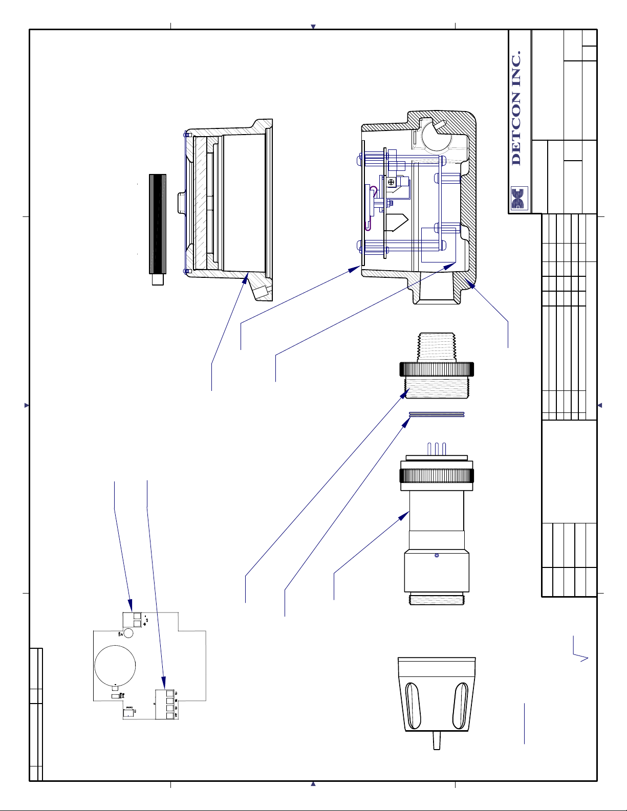
P/N 327-000000-000
Programming Magnet
0
REV
A
3454-2
SIZE
DRAWING NO.
DM-200
NANTS
Breakaway and wiring
_
NA
3200 Research Forest Dr. A-1 * The Woodlands Texas 77381 * www.detcon.com
CLIENT:
NA
PROJECT:
detcon, inc.
NA
SALES ORDER NO.
DETCON PRPOSAL #
SCALE
09/03/09
P. POXON
DRAWN BY:
FIRST ISSUE:
SUBJECT
RELEASE
REF. DWGS
3454
DWG #
BM
APPD
RHPP
DRN CHKD
NA
JOB NO.
terminal block
Loop powered 4-20 mA
ISM connection
Field Terminals
Packet
P/N 922-000000-000
P/N 960-202200-000
P/N 897-850700-000
DM-200 Universal Xmtr Module
Condensation Prevention
Enclosure Glass Lense Cover
DESCRIPTION
ISSUED FOR APROVAL
REVISION HISTORY
09/03/090
Rev DATE
3-Port Enclosure - P/N 897-850800-000
this document may be used and disseminated
The information and technical data disclosed by
NA
P.O. NO.
not be used or disseminated except as provided
only for the purposes and to the extent
in writing. Such information and technical data
are proprietary to Detcon Incorporated and may
in the foregoing sentence.
specifically authorized by Detcon Incorporated
NA
NANANA
PROJECT NO.
SERIAL NO.
REQ. NO.
PLANT:
63
SIZE
A
DRAWING NO.
3454-2
REV
0
P/N 602-003267-000
P/N 392-XXXX0S-YYY
P/N 017-139125-400
Connector Base Assembly
O'Ring Quattro 1.25"ID X .139T
(where XXXX refers to Cell and Gas,
Intelligent Sensor Module with sensor
and YYY refers to the Range.
Refer to Manual for more information)
Splashguard - P/N 613-120000-700
NOTES:
Page 46

Model DM-200
This page left intentionally blank
Model DM-200 Rev. 2.0
Page 47
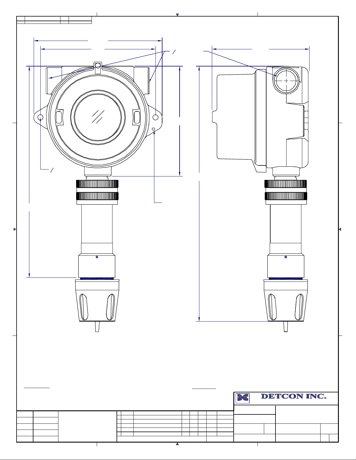
0
REV
3454-1
DRAWING NO.
JOB NO.
NA
A
SIZE
6.125"
3
NPT Ports
4
4.65"5.5"
5.25"
1
" mounting
4
holes
12.2"
10.1"
8-32 Tapped
ground point
NOTES:
P.O. NO.
REQ. NO.
PROJECT NO.
SERIAL NO.
PLANT:
The information and technical data disclosed by
NA
this document may be used and disseminated
only for the purposes and to the extent
NA
specifically authorized by Detcon Incorporated
NA
in writing. Such information and technical data
are proprietary to Detcon Incorporated and may
NA
not be used or disseminated except as provided
in the foregoing sentence.
NA
Rev DATE DESCRIPTION
ISSUED FOR APPROVAL09/03/090 3454BMRHPP RELEASE
REVISION HISTORY
Tolerances:
X.X ± 0.05
X.XX ± 0.015
X.XXX ± 0.005
DWG #APPDDRN CHKD SUBJECT
REF. DWGS
detcon, inc.
CLIENT:
PROJECT:
NA
DRAWN BY:
P POXON
FIRST ISSUE:
3200 Research Forest Dr. A-1 * The Woodlands Texas 77381 * www.detcon.com
NA
_
DM-200
Dimensional Outline
SALES ORDER NO.
SCALE
NANTS
09/03/09
DETCON PRPOSAL #
NA
DRAWING NO.
3454-1
SIZE REV
A
0
Page 48

Model DM-200
This page left intentionally blank
Model DM-200 Rev. 2.0
Page 49
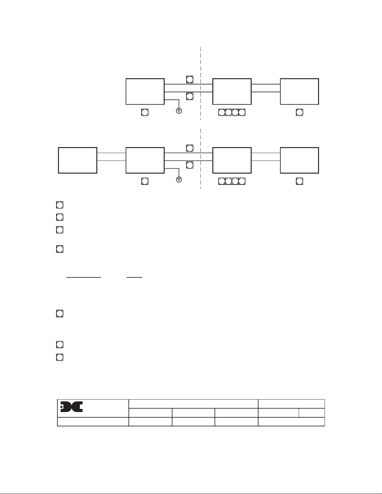
Hazardous Area Safe Area
Class I, Group A, B, C and D;
Loop +
DM-200 BARRIER
1 2 3 4 5 6
DM-200-RS DM-200-RT BARRIER
1 2 3 4 5 6
7
Intrinsically safe wiring.
6
Control equipment must not use or generate more than 250 V with respect to earth.
5
Barriers must be installed in accordance with barrier manufacturer’s control drawing and article 504 of the
Loop –
Loop +
Loop –
7
CONTROL
7
7
EQUIPMENT
CONTROL
7
EQUIPMENT
National Electrical Code ANSI/NFPA 70, CEC Part 1 or other local installation codes, as applicable.
Selected barriers must be third party approved as intrinsically safe for the application and have Voc not
4
exceeding Vmax and Isc not exceeding Imax of the intrinsically safe equipment, as shown in Table 1.
Table 1:
I.S. Equipment Barrier
Vmax
Imax
Ci + Ccable
Li + Lcable
3
Cable capacitance plus intrinsically safe equipment capacitance must be less than the marked capacitance
≥
≥
ʺ
ʺ
Voc
Isc
Ca
La
(Ca) shown on any barrier used. The same applies for inductance. Capacitance and inductance of field wiring
from the intrinsically safe equipment to the barrier should be calculated as (Ccable - 60pF/ft and Lcable = 0.2
uH/ft) and should be included in the system calculations.
2
Barrier may be in Division 2 location is so approved.
1
DM-200 and DM-200-RT entity parameters:
Vmax = 30Vdc
Imax = 300mA
Ci = 30nF
Li = 0
detcon inc.
MATERIAL
3200 A-1 Research Forest Dr.
The Woodlands, TX 77381
TITLE
DM-200 Intrinsically Safe Installation Notes
DRN BY
FINISH
TED S.
SCALE
SHEET OF
11
APPROVED BY
STOCK #
DWG #
2633
DATE
4-15-04 0
STATUS
REV #
Page 50

Model DM-200
This page left intentionally blank
Model DM-200 Rev. 2.0
 Loading...