


INSTRUCTION MANUAL
Detcon Model TP-524D
PGM 
 1
1
MODEL HOUSTON, TEXAS TP-524D
MicroSafeTM H2S Gas Sensor
ALM ALM
FLT 1 2 CAL
PGM 
 2
2
TP-524D Hydrogen Sulfide Sensor
This manual covers the following ranges: 0-20ppm, 0-50ppm, and 0-100ppm
 DETCON, Inc.
4055 Technology Forest Blvd, Suite 100,
The Woodlands, Texas 77381
Ph.281.367.4100 / Fax 281.298.2868
www.detcon.com
March 10, 2014 • Document #3269 • Revision 0.5

Model TP-524D
This page left intentionally blank
Model TP-524D |
ii |

|
|
|
Model TP-524D |
|
|
|
Table of Contents |
|
|
1. |
Introduction .................................................................................................................................................. |
1 |
||
|
1.1 |
Description.......................................................................................................................................... |
1 |
|
|
1.2 |
Modular Mechanical Design............................................................................................................... |
2 |
|
2. |
Installation .................................................................................................................................................... |
4 |
||
|
2.1 |
ATEX Operational Guidelines for Safe Use....................................................................................... |
4 |
|
|
2.2 |
Sensor Placement ................................................................................................................................ |
4 |
|
|
2.3 |
Sensor Contaminants and Interference ............................................................................................... |
5 |
|
|
2.4 |
Mounting Installation.......................................................................................................................... |
6 |
|
|
2.5 |
Electrical Installation .......................................................................................................................... |
7 |
|
|
2.6 |
Field Wiring ........................................................................................................................................ |
8 |
|
|
2.7 |
Initial Start Up..................................................................................................................................... |
9 |
|
3. |
Operation .................................................................................................................................................... |
11 |
||
|
3.1 |
Programming Magnet Operating Instructions................................................................................... |
11 |
|
|
3.2 |
Operator Interface ............................................................................................................................. |
12 |
|
|
3.3 |
Normal Operation ............................................................................................................................. |
14 |
|
|
3.4 |
Calibration Mode (AutoSpan)........................................................................................................... |
14 |
|
|
3.5 |
Program Mode .................................................................................................................................. |
16 |
|
|
3.5.1 |
View Sensor Status....................................................................................................................... |
16 |
|
|
3.5.2 |
Set AutoSpan Level ...................................................................................................................... |
18 |
|
|
3.5.3 |
Set Range...................................................................................................................................... |
18 |
|
|
3.5.4 |
Set Heater Power .......................................................................................................................... |
19 |
|
|
3.5.5 |
Signal Output Check..................................................................................................................... |
20 |
|
|
3.5.6 |
Restore Factory Defaults .............................................................................................................. |
20 |
|
|
3.5.7 Alarm 1 and 2 Settings ................................................................................................................. |
21 |
||
|
3.5.8 |
Fault Settings ................................................................................................................................ |
21 |
|
|
3.6 |
Program Features .............................................................................................................................. |
22 |
|
|
3.6.1 |
Operational Features..................................................................................................................... |
22 |
|
|
3.6.2 |
Fault Diagnostic/Failsafe Features ............................................................................................... |
22 |
|
4. |
Service and Maintenance............................................................................................................................ |
25 |
||
5. |
Troubleshooting Guide ............................................................................................................................... |
27 |
||
6. |
Customer Support and Service Policy ........................................................................................................ |
30 |
||
7. |
TP-524D Sensor Warranty ......................................................................................................................... |
31 |
||
8. |
Appendix .................................................................................................................................................... |
32 |
||
|
8.1 |
Specifications.................................................................................................................................... |
32 |
|
|
8.2 |
Spare Parts, Sensor Accessories, Calibration Equipment ................................................................. |
34 |
|
|
8.3 |
Revision Log..................................................................................................................................... |
35 |
|
Model TP-524D |
iii |

|
|
Model TP-524D |
|
Table of Figures |
|
Figure 1 Sensor Assembly Front View ................................................................................................................ |
1 |
|
Figure 2 Circuit Functional Block Diagram......................................................................................................... |
2 |
|
Figure 3 Transmitter Module ............................................................................................................................... |
2 |
|
Figure 4 Field Replaceable H2S Sensor................................................................................................................ |
3 |
|
Figure 5 |
Base Connector Board ........................................................................................................................... |
3 |
Figure 6 TP 524D ATEX Approval Labels.......................................................................................................... |
4 |
|
Figure 7 |
Typical Outline and Mounting Dimensions........................................................................................... |
7 |
Figure 8 |
Typical Installation ................................................................................................................................ |
8 |
Figure 9 |
Sensor Connector PCB........................................................................................................................... |
9 |
Figure 10 Magnetic Programming Tool ............................................................................................................. |
11 |
|
Figure 11 Magnetic Programming Switches ...................................................................................................... |
11 |
|
Figure 12 TP-524D Software Flowchart ............................................................................................................ |
13 |
|
Figure 13 Replaceable H2S Sensor..................................................................................................................... |
27 |
|
|
List of Tables |
|
Table 1 Cross Interference Gases ......................................................................................................................... |
6 |
|
Table 2 Wire Gauge vs. Distance ......................................................................................................................... |
8 |
|
|
Shipping Address: 4055 Technology Forest Blvd, Suite 100, The Woodlands Texas 77381 |
|
Mailing Address: P.O. Box 8067, The Woodlands Texas 77387-8067 |
|
Phone: 888.367.4286, 281.367.4100 • Fax: 281.292.2860 • www.detcon.com • sales@detcon.com |
Model TP-524D |
iv |

Model TP-524D
1.Introduction
1.1Description
Detcon Model TP-524D hydrogen sulfide sensors are non-intrusive “Smart” sensors designed to detect and monitor H2S in air. Ranges of detection are 0-20ppm, 0-50ppm, and 0-100ppm. The sensor features an LED display of current reading, fault, and calibration status. The Sensor is equipped with a standard analog 4- 20mA output. A primary feature of the sensor is its method of automatic calibration, which guides the user through each step via fully scripted instructions displayed on the LED display.
The microprocessor-supervised electronics are packaged as a plug-in replaceable Transmitter Module that is housed in an explosion proof junction box. The Transmitter Module includes a four character alpha/numeric LED used to display sensor readings, and the sensor’s menu driven features when the hand-held programming magnet is used.
PGM 
 1
1
MODEL HOUSTON, TEXAS TP-524D
MicroSafeTM H2S Gas Sensor
ALM ALM
FLT 1 2 CAL
PGM 
 2
2
Figure 1 Sensor Assembly Front View
Solid State H2S Sensor Technology
The sensor technology is a patented solid-state mixed metal oxide semiconductor. The sensor consists of two thin films, a temperature sensitive heater film, and a hydrogen sulfide sensitive sensor film. Both films are deposited on a silicon microchip by vacuum deposition. The heater film elevates the operating temperature of the sensor film to a level where a good sensitivity and response to hydrogen sulfide is achieved. The sensor film is a proprietary mixed metal oxide that shows an extremely stable and dynamic response to hydrogen sulfide gas.
Range of sensitivity is from parts per billion to percent by volume. The rugged sensor is capable of maintaining its operating characteristics for periods of up to 7- 10 years in most industrial environments and as such, is supported by a 10-year conditional warranty.
TP-524D Instruction Manual |
Rev. 0.5 |
Page 1 of 36 |

Model TP-524D
Principle of Operation
Method of detection is by diffusion/adsorption. Air and H2S diffuse through a sintered stainless steel filter (flame arrestor) and contact the heated surface of the metal oxide sensor film. As hydrogen sulfide gas molecules react with oxygen ions on the film, there is a decrease in electrical resistance proportional to the gas concentration. The heater film elevates the temperature of the sensor film creating convection and promoting a quick response to changing gas concentrations. Electronically, the heater film is used to maintain a constant temperature of the sensor film enhancing stability and repeatability. The sensor response is reversible and results in continuous monitoring of ambient air conditions.
1.2 Modular Mechanical Design
The Model TP-524D Sensor Assembly is completely modular and is made up of four parts:
1)TP-524D Plug-in Transmitter
2)Field Replaceable H2S Gas Sensor
3)Connector PCB
4)Splash Guard.
TP-524D Plug-in Transmitter
The Plug-in Transmitter Module is a microprocessor-based package that plugs into the connector board located in the explosion proof junction box. Circuit functions include extensive I/O circuit protection, sensor preamplifier, sensor temperature control, on-board power supplies, microprocessor, LED display, magnetic programming switches, and a linear 4-20mA DC output. Magnetic program switches located on either side of the LED Display are activated via a hand-held magnetic programming tool, thus allowing non-intrusive operator interface with the Transmitter Module. Calibration can be accomplished without declassifying the area. Electrical classifications are Class I, Division 1, Groups B C D.
|
Pre-Amp |
|
|
|
|
Display |
|
|
|
|
|
|
|
||
|
|
|
Micro- |
|
|
|
Analog 4-20mA Out |
|
|
|
|
|
|||
Plug-In |
Temperature |
|
Processor |
|
|
RS-485 |
I/O |
Sensor |
|
|
|
|
Circuit |
||
Control |
|
|
|
|
|
||
Element |
|
|
|
|
|
Protection |
|
|
|
|
|
|
|
4-20mA |
|
|
|
|
|
|
|
|
|
|
|
|
|
|
|
|
|
Power In
Power Supply
Figure 2 Circuit Functional Block Diagram
PGM 
 1
1
HOUSTON, TEXAS
MicroSafeTM H2S Gas Sensor
ALM ALM
FLT 1 2 CAL
PGM 
 2
2
Figure 3 Transmitter Module
TP-524D Instruction Manual |
Rev. 0.5 |
Page 2 of 36 |
Model TP-524D
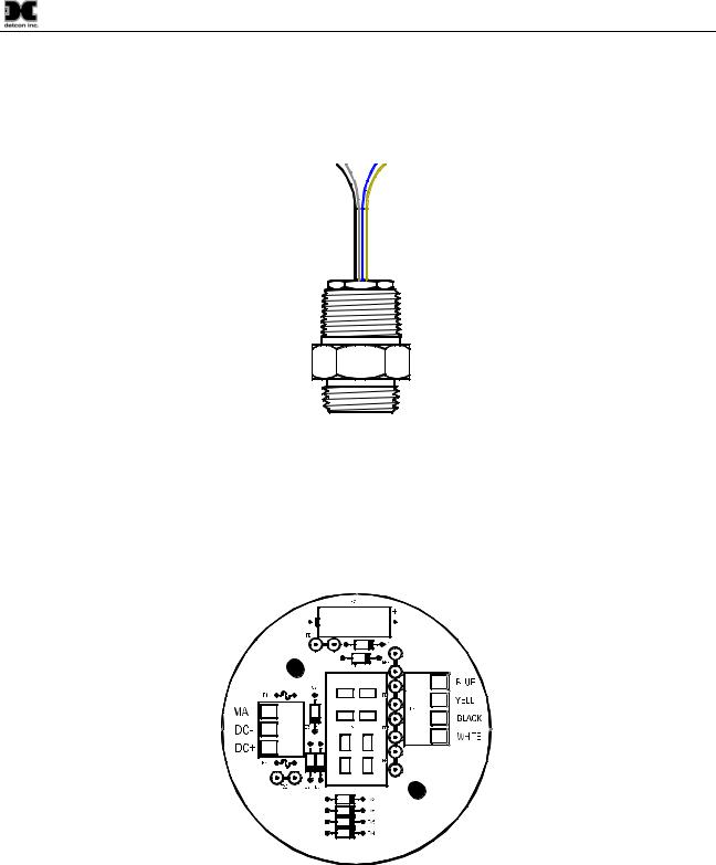
Field Replaceable Sensor
The Detcon solid-state H2S gas sensor is a field proven, replaceable type sensor. It can be accessed and replaced in the field by removing the wiring from the connector PCB, and unthreading the Sensor from the junction box. The Detcon solid state H2S sensor has an infinite shelf life and is supported by a 10 year, industry-leading warranty.
Figure 4 Field Replaceable H2S Sensor
NOTE: The Field Replaceable H2S Gas Sensor is constructed from 316 Stainless Steel in order to maximize corrosion resistance in harsh environments.
Base Connector PCB
The base connector board is mounted in the Junction Box. The connector board includes Lug less terminal connections for incoming power and MA output, and connections for the H2S Replaceable Sensor.
|
Wiring to |
Customer |
H2S Sensor |
Wiring |
|
Figure 5 Base Connector Board
TP-524D Instruction Manual |
Rev. 0.5 |
Page 3 of 36 |

Model TP-524D
2. Installation
2.1ATEX Operational Guidelines for Safe Use
1.Install sensor only in areas with classifications matching with those described on the approval label. Follow all warnings listed on the label.
DETCON, THE WOODLANDS, TEXAS, USA |
|
MODEL TP-524D |
|
RATED: 12-28VDC, 100 mA @ 24VDC |
detcon, inc. |
Serial # |
|
SIRA |
09ATEX1351X |
|
|
||
Date Code |
0035 |
II 2 G Ex d IIB +H2 T4 |
|
|
|
Tamb = -40°C to +60°C |
|
WARNING:Keep cover tight while circuits are Alive. WARNING:Understand manual before operating
DETCON, THE WOODLANDS, TEXAS, USA |
|
MODEL TP-524D |
|
RATED: 12-28VDC, 100 mA @ 24VDC |
detcon, inc. |
Serial # |
|
SIRA |
09ATEX1351X |
|
|
||
Date Code |
0035 |
II 2 G Ex d IIB +H2 T4 |
|
|
|
T amb = -20°C to +60°C |
|
WARNING:Keep cover tight while circuits are Alive. WARNING:Understand manual before operating
Figure 6 TP 524D ATEX Approval Labels
Detcon Condulets |
Killark Condulets |
2.Ensure that the sensor is properly mounted in a vertical orientation with sensor facing down. Avoid use of Teflon Tape, or any type of non-conductive pipe thread coating on the NPT threaded connection.
3.Use ¾” NPT plugs properly rated for hazardous locations to block any unused connections
4.Removal of the Junction box cover or threaded sensor housing (399-800000-000) violates the Ex d protection method and hence power must be removed from the sensor prior its safe removal.
5.Proper precautions should be taken during installation and maintenance to avoid the build-up of static charge on the plastic components of the sensor. These include the splashguard and splashguard adapter.
6.Do not operate the sensor outside of the stated operating temperature limits.
7.Do not operate the sensor outside the stated operating limits for voltage supply.
8.These sensors meet EN60079-0, EN60079-1.
2.2Sensor Placement
Selection of sensor location is critical to the overall safe performance of the product. Five factors play an important role in selection of sensor locations:
(1)Density of the gas to be detected
(2)Most probable leak sources within the industrial process
(3)Ventilation or prevailing wind conditions
(4)Personnel exposure
(5)Maintenance access
(6)Additional Placement Considerations
Density
Placement of sensors relative to the density of the target gas is such that sensors for the detection of heavier than air gases should be located within 4 feet of grade as these heavy gases will tend to settle in low lying
TP-524D Instruction Manual |
Rev. 0.5 |
Page 4 of 36 |

Model TP-524D
areas. For gases lighter than air, sensor placement should be 4-8 feet above grade in open areas or in pitched areas of enclosed spaces.
Note: H2S is heavier than air.
Leak Sources
The most probable leak sources within an industrial process include flanges, valves, and tubing connections of the sealed type where seals may either fail or wear. Other leak sources are best determined by facility engineers with experience in similar processes.
Ventilation
Normal ventilation or prevailing wind conditions can dictate efficient location of gas sensors in a manner where the migration of gas clouds is quickly detected.
Personnel Exposure
The undetected migration of gas clouds should not be allowed to approach concentrated personnel areas such as control rooms, maintenance or warehouse buildings. A more general and applicable thought toward selecting sensor location is combining leak source and perimeter protection in the best possible configuration.
Maintenance Access
Consideration should be given to providing easy access for maintenance personnel. Consideration should also be given to the consequences of close proximity to contaminants that may foul the sensor prematurely.
NOTE: In all installations the gas sensor should point straight down (refer to Figure 8). Improper sensor orientation may result in false readings and permanent sensor damage.
Additional Placement Considerations
The sensor should not be positioned where it may be sprayed or coated with surface contaminating substances. Painting sensor assemblies is prohibited.
Although the sensor is designed to be RFI resistant, it should not be mounted in close proximity to highpowered radio transmitters or similar RFI generating equipment.
When possible mount in an area void of high wind, accumulating dust, rain, or splashing from hose spray, direct steam releases, and continuous vibration. If the sensor cannot be mounted away from these conditions then make sure the Detcon Harsh Location Dust Guard accessory is used.
Do not mount in locations where temperatures will exceed the operating temperature limits of the sensor. Where direct sunlight leads to exceeding the high temperature-operating limit, use a sunshade to help reduce temperature.
2.3 Sensor Contaminants and Interference
Solid State H2S sensors may be adversely affected by exposure to certain airborne substances. Loss of sensitivity or corrosion may be gradual if such materials are present in sufficient concentrations.
The more common materials that potentially cause problems with the sensors are as follows:
Silicone vapors such as those found in greases and lubricants
TP-524D Instruction Manual |
Rev. 0.5 |
Page 5 of 36 |

Model TP-524D
Halide Compounds containing Chlorine, Chlorine Dioxide, Fluorine, HF, HCl, and Bromine Caustic and Acid liquids and concentrated vapors
Heavy metals such as tetraethyl lead Heavy and complex VOC gasses
The presence of such contaminants in an area does not preclude the use of this H2S sensor technology, although it is likely that the sensor lifetime will be shorter as a result. Use of this sensor in these environments may require more frequent calibration checks to ensure safe system performance.
Solid State H2S sensors require O2 in the background gas and the reading is affected by changing O2 levels.
Interference Data
There are some gases typically found in industrial environments that can cause a cross-interference response on the sensor. See the Table below for some examples.
|
|
|
|
|
Table 1 Cross Interference Gases |
|
|
|
|||
|
GAS |
|
|
PPM |
|
|
GAS |
|
|
PPM |
|
|
|
|
|
|
|
|
|
|
|
|
|
|
Methane |
|
25,000 = 0 |
|
|
Ammonia |
|
500 = 1 |
|
||
|
Ethane |
|
5,000 = 0 |
|
|
Diesel Fuel |
|
1000 = 0 |
|
||
|
Hexane |
|
5,000 = 0 |
|
|
Dimethyl Sulfide |
|
4.4 = 0 |
|
||
|
Propane |
|
5,000 = 0 |
|
|
Ethylene |
|
200 = 0 |
|
||
|
Butane |
|
5,000 = 0 |
|
|
Freon 12 |
|
1,000 = 0 |
|
||
|
Carbon Monoxide |
|
1% = 0 |
|
|
Hydrogen |
|
5% = 0 |
|
||
|
Carbon Dioxide |
|
5,000 = 0 |
|
|
Methyl Mercaptan |
|
10 = 0 |
|
||
|
Carbon Disulfide |
|
14 = 0 |
|
|
Sulfur Dioxide |
|
300 = 0 |
|
||
|
Methanol |
|
500 = 5 |
|
|
Toluene |
|
32 = 0 |
|
||
|
Isopropanol |
|
500 = 3 |
|
|
Ethanol |
|
500 = 5 |
|
||
NOTE: The Detcon MOS Sensor Cell can be damaged to the point of non-functioning if the unit is left off power and in the presence normal air levels of moisture for periods exceeding 8 hours.
NOTE: Always protect the sensor cell with the Detcon Sealing Cap and a fresh desiccant packet when the sensor is powered off, this will avoid permanent sensor cell damage and help preserve the span calibration.
2.4 Mounting Installation
The TP-524D should be vertically oriented so that the sensor points straight downward. The explosion-proof enclosure or junction box would then typically be mounted on a wall or pole (See Figure 7). Detcon provides a selection of standard junction boxes in both Aluminum and Stainless Steel.
NOTE: Do not use Teflon Tape or any other type of Pipe Thread material on the ¾” threads unless the unit is mounted in a severe or harsh environment. Metal-on-metal contact must be maintained to provide a solid electrical ground path. If Teflon Tape is used the Sensor must be externally grounded using a ground strap.
When mounting on a pole, secure the Junction Box to a suitable mounting plate and attach the mounting plate to the pole using U-Bolts. (Pole-Mounting brackets for Detcon Junction Box’s are available separately.)
TP-524D Instruction Manual |
Rev. 0.5 |
Page 6 of 36 |

Model TP-524D
|
6.125" |
|
|
||
|
|
5.5" |
3 4 NPT Ports |
4.6" |
|
|
|
PGM |
1 |
|
|
|
MODEL HOUSTON, TEXAS TP-524D |
|
|
||
|
MicroSafeTM H2S Gas Sensor |
5.25" |
|
||
|
|
ALM ALM |
|
|
|
6.45" |
FLT |
1 |
2 CAL |
|
|
|
PGM |
2 |
|
|
|
|
|
|
|
||
|
|
|
|
8-32 tapped |
|
|
|
|
|
ground point |
|
|
14" mounting holes |
|
|
|
|
|
|
|
|
H2S Sensor |
|

 2.1"
2.1" 

Splash Guard
2"
Wall (or other mounting surface)
Figure 7 Typical Outline and Mounting Dimensions
2.5 Electrical Installation
The Sensor Assembly should be installed in accordance with local electrical codes. The sensor assemblies are FM and CSA/NRTL approved (US and Canada) for Class I, Division 1, Groups B, C, & D area classifications.
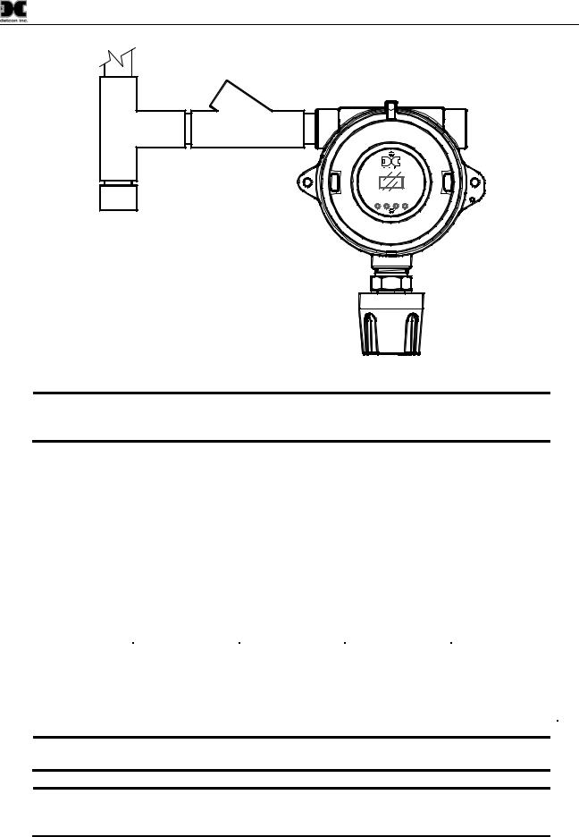
Proper electrical installation of the gas sensor is critical for conformance to Electrical Codes and to avoid damage due to water leakage. Refer to Figure 8 and Figure 9 for proper electrical installation.
NOTE: If a conduit run exits the secondary port, repeat the installation technique shown in Figure 8.
In Figure 8, the drain allows H2O condensation inside the conduit run to safely drain away from the sensor assembly. The electrical seal fitting is required to meet the National Electrical Code per NEC Article 500-3d (or Canadian Electrical Code Handbook Part 1 Section 18-154). Requirements for locations of electrical seals are covered under NEC Article 501-5. Electrical seals also act as a secondary seal to prevent water from entering the wiring terminal enclosure. However, they are not designed to provide an absolute watertight seal, especially when used in the vertical orientation.
NOTE: A conduit seal is typically required to be located within 18" of the J-Box and Sensor Assembly. Crouse Hinds type EYS2, EYD2 or equivalent are suitable for this purpose.
NOTE: The Detcon Warranty does not cover water damage resulting from water leaking into the enclosure.
TP-524D Instruction Manual |
Rev. 0.5 |
Page 7 of 36 |
Model TP-524D
Conduit |
|
"T" |
EYS Seal Fitting |
Drain |
|
PGM 
 1
1
MODEL HOUSTON, TEXAS TP-524D
MicroSafeTM H2S Gas Sensor
ALM ALM
FLT 1 2 CAL
PGM 
 2
2
Figure 8 Typical Installation
NOTE: Any unused ports should be blocked with suitable ¾” male NPT plugs. Detcon supplies one ¾” NPT male plug with each J-box enclosure. If connections are other than ¾” NPT, use an appropriate male plug of like construction material.
2.6 Field Wiring
Detcon Model TP-524D solid-state H2S sensor assemblies require three conductor connections between power supplies and host electronic controller’s 4-20mA output. A 250 ohm load resistor is needed on the 4-20 mA line when it is not being used. Wiring designations are DC+, DC-, MA (sensor signal). The maximum wire length between sensor and 24VDC source is shown in the Table below. The maximum wire size for termination in the Junction Box is 14 AWG.
Table 2 Wire Gauge vs. Distance
|
AWG |
|
|
Wire Dia. |
|
|
Meters |
|
|
Feet |
|
|
Over-Current |
|
|
|
|
|
|
|
|
|
|
Protection |
|
||||
|
|
|
|
|
|
|
|
|
|
|
|
|
|
|
22 |
|
|
0.723mm |
700 |
|
2080 |
|
|
3A |
|||||
20 |
|
|
0.812mm |
1120 |
|
3350 |
|
|
5A |
|||||
18 |
|
|
1.024mm |
1750 |
|
5250 |
|
|
7A |
|||||
16 |
|
|
1.291mm |
2800 |
|
8400 |
|
|
10A |
|||||
14 |
|
|
1.628mm |
4480 |
|
13,440 |
|
|
20A |
|||||
NOTE 1: Wiring table is based on stranded tinned copper wire and is designed to serve as a reference only.
NOTE 2: Shielded cable is required for installations where cable trays or conduit runs include high voltage lines or other possible sources of induced interference. Separate conduit runs are highly recommended in these cases.
TP-524D Instruction Manual |
Rev. 0.5 |
Page 8 of 36 |
 Loading...