

Page 1
INSTRUCTION MANUAL
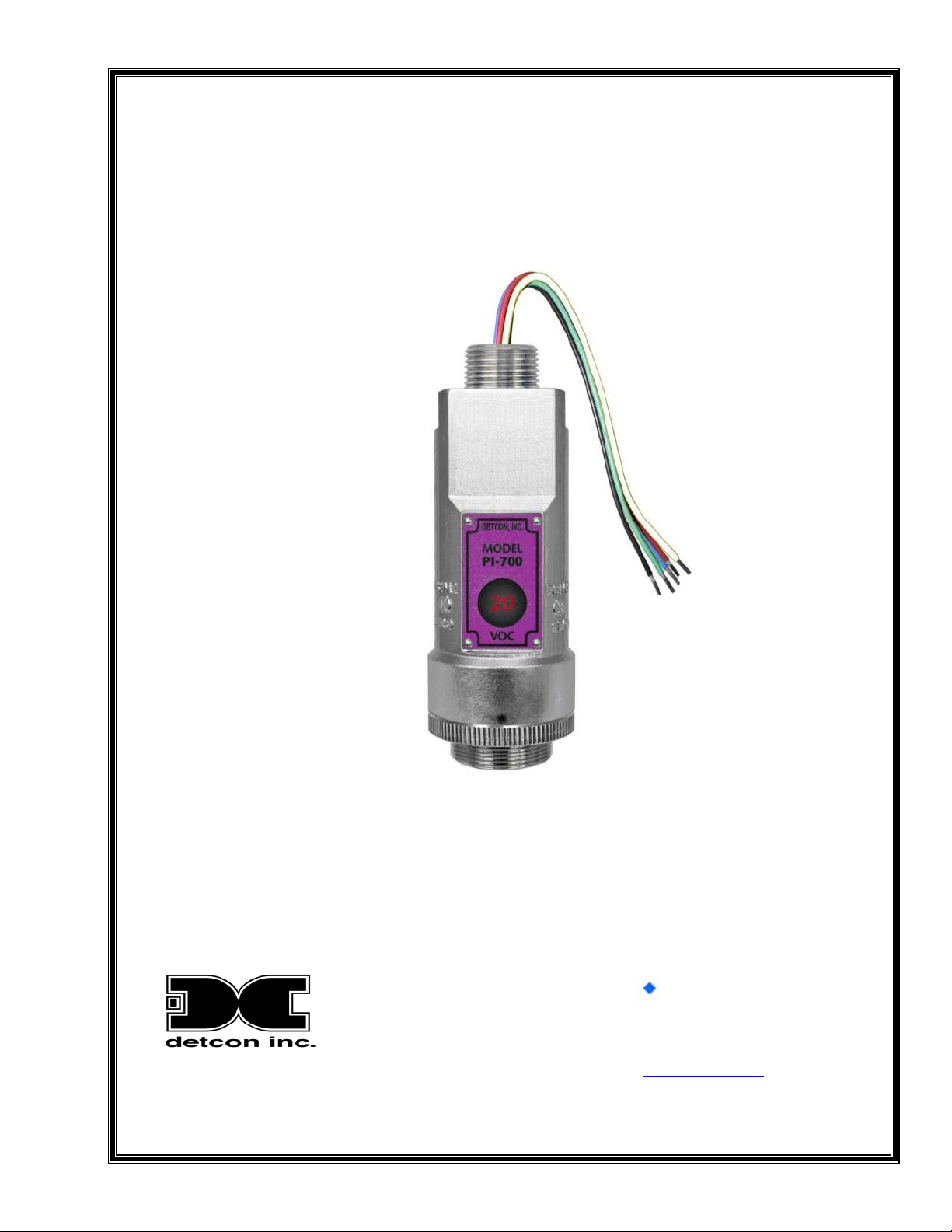
Detcon Model PI-700
PI-700 VOC Gas Sensors
This manual covers all ranges of PID based VOC Sensors
DETCON, Inc.
4055 Technology Forest Blvd.,
The Woodlands, Texas 77381
Ph.281.367.4100 / Fax 281.298.2868
www.detcon.com
April 15, 2014 • Document #3228 • Revision 2.5
Page 2

Model PI-700
Model PI-700 ii
Page 3

Model PI-700
Table of Contents
1. Introduction ..................................................................................................................................................1
1.1 Description.......................................................................................................................................... 1
1.2 Sensor Electronics Design .................................................................................................................. 1
1.3 Modular Mechanical Design............................................................................................................... 2
1.4 Intelligent Plug-in PID Gas Sensor..................................................................................................... 3
2. Installation....................................................................................................................................................4
2.1 ATEX Operational Guidelines for Safe Use....................................................................................... 4
2.2 Sensor Placement................................................................................................................................ 5
2.3 Sensor Contaminants and Interference ............................................................................................... 6
2.4 Mounting Installation.......................................................................................................................... 6
2.5 Electrical Installation .......................................................................................................................... 7
2.6 Field Wiring........................................................................................................................................ 8
2.7 Initial Start Up................................................................................................................................... 10
3. Operation....................................................................................................................................................12
3.1 Programming Magnet Operating Instructions................................................................................... 12
3.2 Operator Interface............................................................................................................................. 13
3.3 Normal Operation ............................................................................................................................. 14
3.4 Calibration Mode .............................................................................................................................. 15
3.4.1 AutoZero....................................................................................................................................... 15
3.4.2 AutoSpan...................................................................................................................................... 15
3.5 Program Mode .................................................................................................................................. 18
3.5.1 View Sensor Status....................................................................................................................... 18
3.5.2 Set AutoSpan Level...................................................................................................................... 20
3.5.3 Set Serial ID ................................................................................................................................. 21
3.5.4 Set Range...................................................................................................................................... 21
3.5.5 Set Gas Factor............................................................................................................................... 22
3.5.6 Set Zero Offset.............................................................................................................................. 22
3.5.7 Signal Output Check..................................................................................................................... 23
3.5.8 Restore Factory Defaults.............................................................................................................. 23
3.6 Program Features .............................................................................................................................. 24
3.6.1 Operational Features..................................................................................................................... 24
3.6.2 Fault Diagnostic/Failsafe Features ............................................................................................... 25
4. RS-485 Modbus™ Protocol .......................................................................................................................27
Content Description.............................................................................................................................................27
5. Service and Maintenance............................................................................................................................29
5.1 PID Plug-In Sensor Maintenance...................................................................................................... 29
5.2 Replacement of Intelligent Plug-in Sensor ....................................................................................... 36
5.3 Replacement of ITM......................................................................................................................... 37
5.4 Replacement of PI-700 Sensor Assembly......................................................................................... 38
6. Troubleshooting Guide...............................................................................................................................39
7. Customer Support and Service Policy........................................................................................................42
8. PI-700 Sensor Warranty .............................................................................................................................43
9. Appendix ....................................................................................................................................................44
9.1 Specifications.................................................................................................................................... 44
9.2 Gas Reference Table......................................................................................................................... 46
9.3 Spare Parts, Sensor Accessories, Calibration Equipment................................................................. 53
9.4 Model PI-700 Engineering Drawings ............................................................................................... 54
9.1 Revision History ............................................................................................................................... 54
Model PI-700 iii
Page 4

Model PI-700
Table of Figures
Figure 1 Typical Sensor Cell................................................................................................................................ 1
Figure 2 ITM Circuit Functional Block Diagram................................................................................................. 2
Figure 3 Sensor Assembly Front View ................................................................................................................ 2
Figure 4 Sensor Assembly Breakaway................................................................................................................ 3
Figure 5 Intelligent Plug-in Sensor....................................................................................................................... 3
Figure 6 PI-700 ATEX Approval Label............................................................................................................... 4
Figure 7 Outline and Mounting Dimensions........................................................................................................ 7
Figure 8 Typical Installation................................................................................................................................ 8
Figure 9 Sensor Wire Connections....................................................................................................................... 9
Figure 10 Magnetic Programming Tool............................................................................................................. 12
Figure 11 Magnetic Programming Switches..................................................................................................... 12
Figure 12 PI-700 Software Flowchart................................................................................................................ 14
Figure 14 UV Lamp Aging Expectation ............................................................................................................ 29
Figure 15 Splashguard Adapter with Integral Filter........................................................................................... 30
Figure 16 Plug-in sensor with Moisture control packet ..................................................................................... 30
Figure 17 Sensor Cell Parts................................................................................................................................ 31
Figure 18 Removal of Filter Cap........................................................................................................................ 31
Figure 19 Removal of Filter Media.................................................................................................................... 32
Figure 20 Removal of Spacer............................................................................................................................. 32
Figure 21 Removal of Cell Assembly................................................................................................................ 32
Figure 22 Removal of Lamp .............................................................................................................................. 33
Figure 23 Lamp cleaning.................................................................................................................................... 33
Figure 24 Polishing the Lamp ............................................................................................................................ 33
Figure 25 Lamp installation ............................................................................................................................... 34
Figure 26 Lamp seating...................................................................................................................................... 34
Figure 27 Cell Assembly installation................................................................................................................. 34
Figure 28 Spacer installation.............................................................................................................................. 35
Figure 29 Installing Filter Media........................................................................................................................ 35
Figure 30 Replacing the Cap.............................................................................................................................. 35
Figure 31 Sensor Assembly................................................................................................................................ 36
Figure 32 Sensor Cell and ITM Mating ............................................................................................................. 37
Figure 33 Sensor Cell and ITM Mating ............................................................................................................. 39
List of Tables
Table 1 Wire Gauge vs. Distance......................................................................................................................... 9
Table 2 Maximum and Minimum AutoSpan Settings........................................................................................ 20
Table 3 Modbus™ Registers.............................................................................................................................. 27
Table 4 Modbus™ Special Registers ................................................................................................................. 28
Table 3 Gas Factor Table ................................................................................................................................... 46
Shipping Address: 4055 Technology Forest Blvd., The Woodlands Texas 77381
Mailing Address: P.O. Box 8067, The Woodlands Texas 77387-8067
Phone: 888.367.4286, 281.367.4100 • Fax: 281.292.2860 • www.detcon.com • [email protected]
Model PI-700 iv
Page 5
1. Introduction
1.1 Description
Detcon Model PI-700 VOC gas sensors are non-intrusive “Smart” sensors designed
to detect and monitor a wide range of VOC and Toxic gasses in air. Ranges of
detection for target gasses are from 0-1ppm up to 0-5,000ppm. The sensor features
an LED display of current reading, fault and calibration status. The Sensor is
equipped with standard analog 4-20mA and Modbus™ RS-485 outputs. A primary
feature of the sensor is its method of automatic calibration, which guides the user
through each step via fully scripted instructions displayed on the LED display.
The microprocessor-supervised electronics are packaged in an encapsulated
module and housed in an explosion proof casting, called the ITM (Intelligent
Transmitter Module). The ITM includes a four character alpha/numeric LED used
to display sensor readings, and the sensor’s menu driven features when the handheld programming magnet is used.
Sensor Technology
Model PI-700
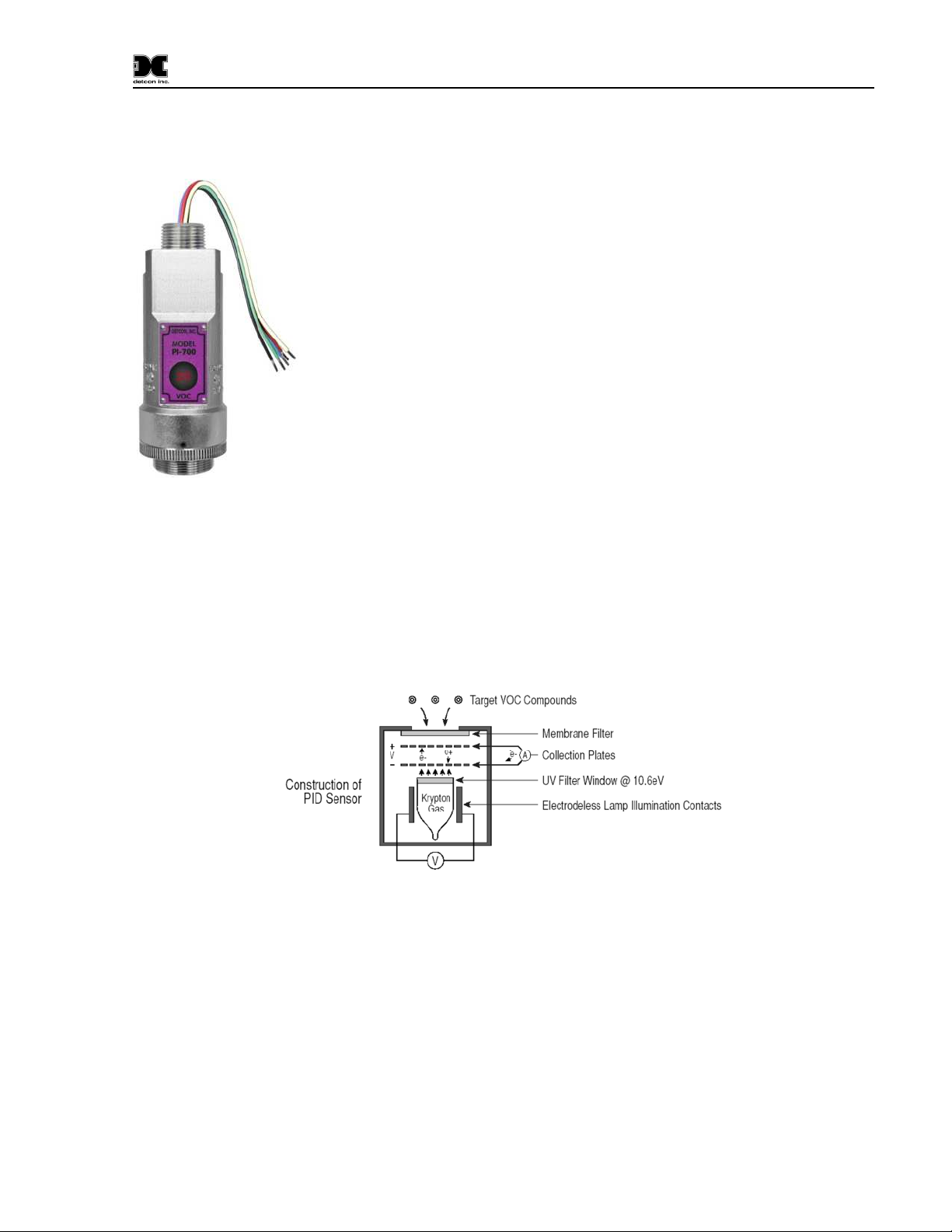
The sensors are based on plug-in replaceable miniature PID (Photo-Ionization Detector) sensor technology.
The sensor is sensitive to ambient gases that have ionization potentials of < 10.6eV, making it highly sensitive
but extremely non-specific. The sensor responds to most toxic VOC compounds and many other toxic gases
as well. The sensor is comprised of a UV lamp covered by a specific optical filter which projects only
radiation in the 10.6eV range. Target gases that diffuse into the sensor chamber with ionization potentials of <
10.6eV, are ionized by the radiation and give up free electrons. The free electrons are captured by the high
voltage collection grid and provide a current that is directly proportional to the concentration of the target gas.
Figure 1 Typical Sensor Cell
1.2 Sensor Electronics Design
Intelligent Transmitter Module
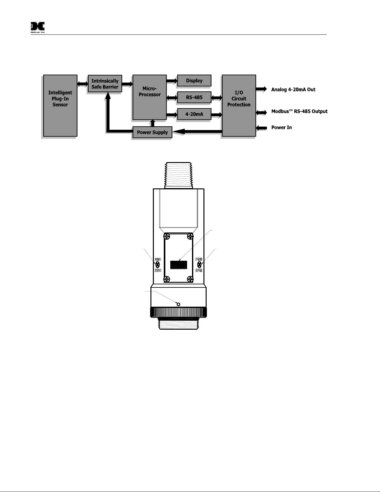
The PI-700 Intelligent Transmitter Module (ITM) is a fully encapsulated microprocessor-based package that is
universal in design and will accept any Detcon intelligent plug-in PID gas sensor. The ITM design uses an
internal intrinsically safe barrier circuit that lifts the requirement for use of flame arrestors to achieve Class 1,
Division 1 (Zone1) area classification. This facilitates fast response times and improved calibration
repeatability on strongly absorbing gas types. The ITM circuit functions include extensive I/O circuit
protection, on-board power supplies, internal intrinsically safe barrier circuit, microprocessor, LED display,
magnetic programming switches, a linear 4-20mA DC output, and a Modbus™ RS-485 output. Magnetic
program switches located on either side of the LED Display are activated via a hand-held magnetic
PI-700 Instruction Manual Rev. 2.5 Page 1 of 54
Page 6
Model PI-700
programming tool, thus allowing non-intrusive operator interface with the ITM. Calibration can be
accomplished without declassifying the area. Electrical classifications are Class I, Division 1, Groups B C D
and are ATEX Approved for Class I, Zone 1, Group IIC area classifications.
Figure 2 ITM Circuit Functional Block Diagram
LED Display
Program Switch #2
Program Switch #1
Splashguard Adapter
Locking Set-Screw
detcon inc.
detcon inc.
MODEL
PI-700
VOC
Figure 3 Sensor Assembly Front View
1.3 Modular Mechanical Design
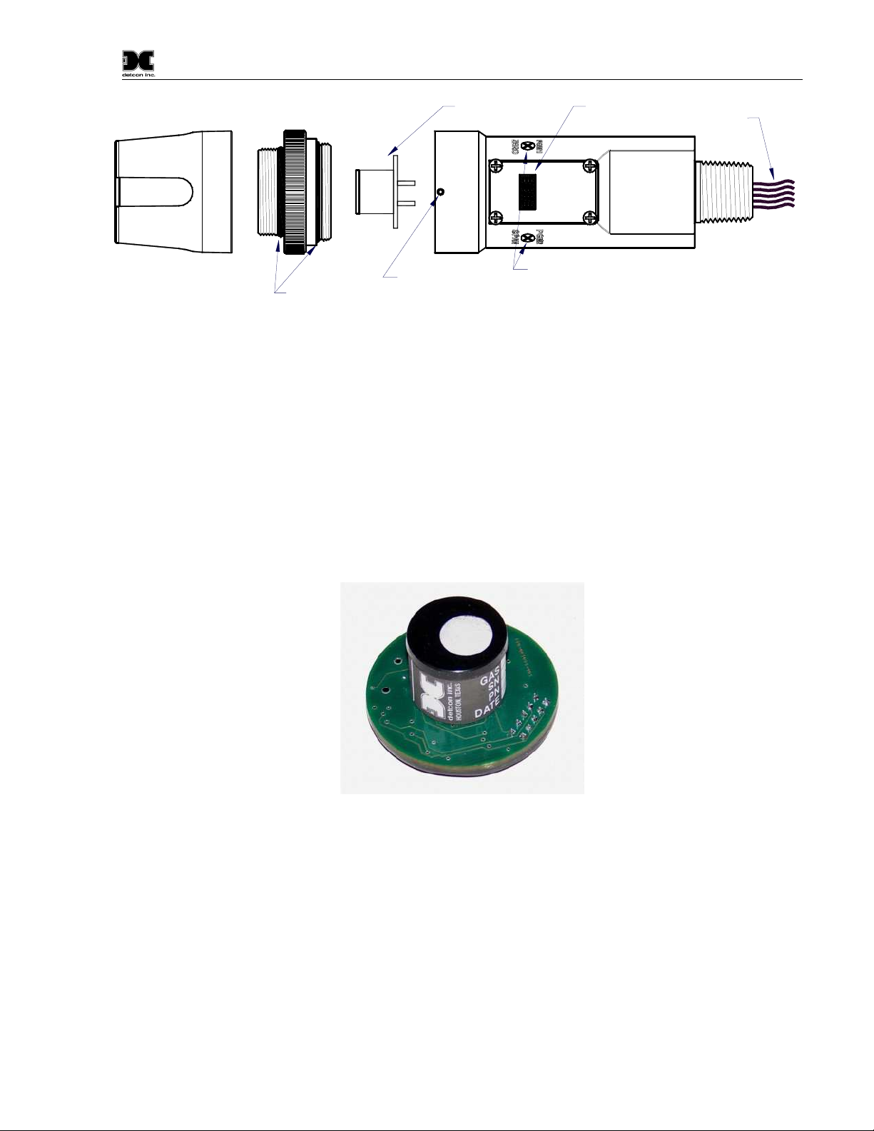
The Model PI-700 Sensor Assembly is completely modular and is made up of four parts (See Figure 4 for
Assembly Break-away):
1) PI-700 Intelligent Transmitter Module (ITM)
2) Intelligent Plug-in Sensor (varies by range)
3) PI-700 Splash Guard Adapter with Integral Filter
4) Splash Guard.
NOTE: All metal components are constructed from electro polished 316 Stainless Steel in order to maximize
corrosion resistance in harsh environments.
PI-700 Instruction Manual Rev. 2.5 Page 2 of 54
Page 7
Model PI-700
Lens and LCD
Display
detcon inc.
MODEL
PI-700
Interconnect Wiring
Intelligent ransmitter Module (ITM)
Microprocessor controlled circuit
encapsulated in an explosion
proof housing
Splash Guard
Splashguard
Adapter
O-Rings
Plug-In replaceable
Sensor Cell
Housing Bottom
Locking Set-Screw
PI-700
VOC
detcon inc.
MODEL
Magnetic
Programming
Switches
Figure 4 Sensor Assembly Breakaway
1.4 Intelligent Plug-in PID Gas Sensor
The Detcon range of PID gas sensors are field proven, intelligent plug-in sensors (one type is used for ranges
of 20ppm and less, another is used for ranges greater than 20ppm.) The Sensors employ 100% encapsulated
circuitry and over-sized gold-plated connections that eliminate corrosion problems. The intelligent design
provides automatic recognition of gas type, units, full-scale range, and calibrations data when a new sensor is
plugged in. The sensor can be accessed and replaced in the field very easily by releasing the locking setscrew
and unthreading the Splashguard Adapter. The PID Sensor cell can be disassembled so that the lamp used can
be cleaned or replaced. Detcon’s ranges of PID sensors has a long shelf life and are supported by an industryleading warranty.
Figure 5 Intelligent Plug-in Sensor
PI-700 Instruction Manual Rev. 2.5 Page 3 of 54
Page 8
Model PI-700
2. Installation
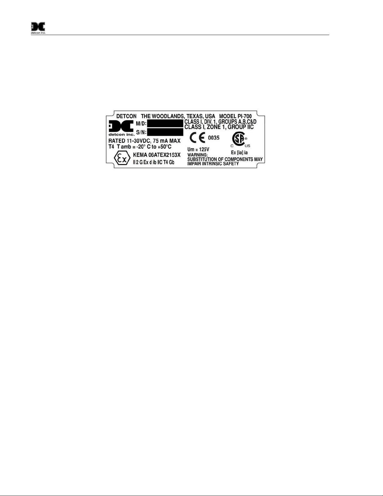
2.1 ATEX Operational Guidelines for Safe Use
1. Install sensor only in areas with classifications matching with those described on the approval label.
Follow all warnings listed on the label.
Figure 6 PI-700 ATEX Approval Label
2. Ensure that the sensor is properly threaded into a suitable explosion-proof rated junction box with a
downward pointing female ¾” NPT threaded connection. The sensor should be threaded up at least 5
full turns until tight, with the LED display facing forward. Avoid use of Teflon Tape, or any type of
non-conductive pipe thread coating on the NPT threaded connection.
3. A good ground connection should be verified between the sensor’s metal enclosure and the junction
box. If a good ground connection is not made, the sensor can be grounded to the junction box using
the sensor’s external ground lug. Also verify a good ground connection between the junction box and
earth ground.
4. Proper precautions should be taken during installation and maintenance to avoid the build-up of static
charge on the plastic components of the sensor. These include the splashguard and splashguard
adapter.
5. Do not substitute components that are not authorized by the scope of the safety approval. This may
impair the intrinsic safety rating.
6. Do not operate the sensor outside of the stated operating temperature limits.
7. Do not operate the sensor outside the stated operating limits for voltage supply.
8. The sensor power supply common (black wire) must be referenced to the metal enclosure body
(ground) during installation.
9. These sensors meet EN60079-0:2009, EN60079-1:2007, EN60079-11:2012 and EN50020.
10. These sensors have a maximum safe location voltage of Um=125V.
11. These sensors pass dielectric strength of 500VRMS between circuit and enclosure for a minimum of 1
minute at a maximum test current of 5mA.
PI-700 Instruction Manual Rev. 2.5 Page 4 of 54
Page 9

Model PI-700
NOTE:
2.2 Sensor Placement
Selection of sensor location is critical to the overall safe performance of the product. Six factors play an
important role in selection of sensor locations:
(1) Density of the gas to be detected
(2) Most probable leak sources within the industrial process
(3) Ventilation or prevailing wind conditions
(4) Personnel exposure
(5) Maintenance access
(6) Additional placement considerations
Density
Placement of sensors relative to the density of the target gas is such that sensors for the detection of heavier
than air gasses should be located within 4 feet of grade as these heavy gasses will tend to settle in low lying
areas. For gasses lighter than air, sensor placement should be 4-8 feet above grade in open areas or in pitched
areas of enclosed spaces.
Leak Sources
The most probable leak sources within an industrial process include flanges, valves, and tubing connections of
the sealed type where seals may either fail or wear. Other leak sources are best determined by facility
engineers with experience in similar processes.
Ventilation
Normal ventilation or prevailing wind conditions can dictate efficient location of gas sensors in a manner
where the migration of gas clouds is quickly detected.
Personnel Exposure
The undetected migration of gas clouds should not be allowed to approach concentrated personnel areas such
as control rooms, maintenance or warehouse buildings. A more general and applicable thought toward
selecting sensor location is combining leak source and perimeter protection in the best possible configuration.
Maintenance Access
Consideration should be given to providing easy access for maintenance personnel. Consideration should also
be given to the consequences of close proximity to contaminants that may foul the sensor prematurely.
All installations of the gas sensor should point straight down (refer to Figure 8).
Improper sensor orientation may result in false readings and permanent sensor damage.
Additional Placement Considerations
The sensor should not be positioned where it may be sprayed or coated with surface contaminating substances.
Painting sensor assemblies is prohibited.
Although the sensor is designed to be RFI resistant, it should not be mounted in close proximity to highpowered radio transmitters or similar RFI generating equipment.
Mount in an area void of high wind, accumulating dust, rain or splashing from hose spray, direct steam
releases, and continuous vibration. If the sensor cannot be mounted away from these conditions then make
sure the Detcon Harsh Environment Splashguard accessory is used.
PI-700 Instruction Manual Rev. 2.5 Page 5 of 54
Page 10

Model PI-700
Do not mount in locations where temperatures will exceed the operating temperature limits of the sensor.
Where direct sunlight leads to exceeding the high temperature-operating limit, use a sunshade to help reduce
temperature.
2.3 Sensor Contaminants and Interference
PID VOC and toxic gas sensors will respond to any gas with an ionization potential <10.6eV. This is not a
selective measurement technique, and hence can be used to measure a wide range of gases.
Some of the most commonly present gasses that potentially cause PID interference are listed in Table 5 Gas
Factor Table (refer to Section 9). The presence of cross-interference gases in an area does not preclude the
use of this sensor technology, although it is likely that the sensor will experience false high readings should
exposure occur.
Some heavy organic molecules may be polymerized onto, or strongly adhere to, the optical filter of the lamp.
When this occurs, the lamp will require cleaning or replacement.
Relative Response Gas Matrix
Table 5 Gas Factor Table shows the response of the PID sensor to a long list of components. It includes the
compound name, synonyms/abbreviations, and chemical formula. It also lists the 10.6eV Response Factor (the
measure of how strong the signal from the sensor is in reference to Isobutylene gas). Isobutylene gas is the
standard reference used with PID sensors, the lower the Response Factor, the stronger the signal.
2.4 Mounting Installation
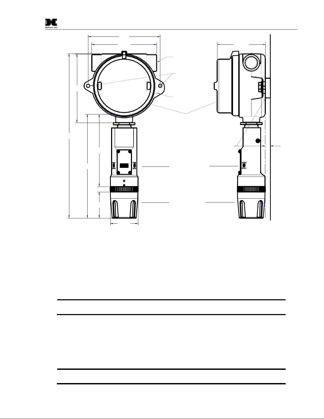
The PI-700 sensor assembly is designed to be threaded into a ¾” Female NPT fitting of a standard cast metal,
Explosion-Proof Enclosure or Junction Box. Two wrench flats on the upper section of the sensor should be
used to thread the sensor into a ¾” female NPT receiving connection. Thread the sensor up until tight (5 turns
is typically expected) and until the display is pointed in the direction that sensor will normally be viewed and
accessed.
The PI-700 should be vertically oriented so that the sensor points straight down. The explosion-proof
enclosure or junction box would then typically be mounted on a wall or pole. Detcon provides a standard
selection of junction boxes available as sensor accessories (See Figure 7 below). Any appropriately rated
enclosure with a downward facing ¾” NPT female connection will suffice.
When mounting on a wall, it is recommended to use a 0.25”-0.5” spacer underneath the mounting ears of the
Detcon standard J-Box to offset the sensor assembly from the wall and create open access around the sensor
assembly. Spacing requirements for other junction boxes may vary.
When mounting on a pole, secure the Junction Box to a suitable mounting plate and attach the mounting plate
to the pole using U-Bolts. (Pole-Mounting brackets for Detcon J-box accessories are available separately.)
PI-700 Instruction Manual Rev. 2.5 Page 6 of 54
Page 11
5.5"
NOTE:
NOTE:
4.95"
Model PI-700
3.675"
3/4" NPT
Ø0.265" x2
Mounting Holes
12.55"
5.25"
7.935"
5.53"
2"
8-32 Thread
Ground Point
Explosion Proof Enclosure
Junction-Box
(Detcon's Junction-Box shown)
Use Spacers to move
the J-Box and Sensor
detcon inc.
MODEL
PI-700
VOC
2.125"
Assembly away from the
wall at least 0.25-0.5" to
allow access to Sensor
Sensor Assembly
Splash Guard
Figure 7 Outline and Mounting Dimensions
Bolt
Mounting
Spacer
Wall (or other
mounting surface)
2.5 Electrical Installation
The Sensor Assembly should be installed in accordance with local electrical codes. The sensor assemblies are
designed for Class I, Division 1, Groups B, C, & D area classifications, and for ATEX Class I, Zone 1, Group
IIC area classifications.
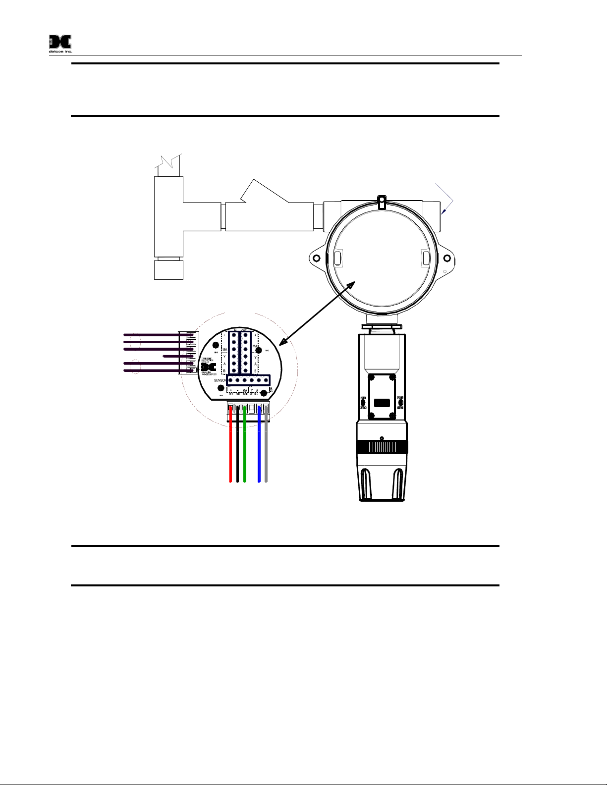
Proper electrical installation of the gas sensor is critical for conformance to Electrical Codes and to avoid
damage due to water leakage. Refer to Figure 8 and Figure 9 for proper electrical installation.
If a conduit run exits the secondary port, repeat the installation technique shown in
Figure 8.
In Figure 8, the drain allows water condensation inside the conduit run to safely drain away from the sensor
assembly. The electrical seal fitting is required to meet the National Electrical Code per NEC Article 500-3d
(or Canadian Electrical Code Handbook Part 1 Section 18-154). Requirements for locations of electrical seals
are covered under NEC Article 501-5. Electrical seals also act as a secondary seal to prevent water from
entering the wiring terminal enclosure. However, they are not designed to provide an absolute water-tight
seal, especially when used in the vertical orientation.
A conduit seal is typically required to be located within 18" of the J-Box and Sensor
Assembly. Crouse Hinds type EYS2, EYD2 or equivalent are suitable for this purpose.
PI-700 Instruction Manual Rev. 2.5 Page 7 of 54
Page 12
Model PI-700
NOTE:
NOTE:
The Detcon Warranty does not cover water damage resulting from water leaking into
the enclosure. Since the electronics are 100% epoxy encapsulated, only the wire terminations
can get wet. This could cause abnormal operation and possibly cause corrosion to the terminal
connections. However, it would not be expected to cause permanent damage to the sensor.
Conduit
"T"
Drain
Customer
Supplied Wiring
Transient Protection Module
(TPM) P/N 500-003087-100
mA
N/U
A(+)
B(-)
(+)
(-)
Mount TPM in Explosion
Proof Enclosure to ground
unit properly. Mount to
bottom of enclosure using
6-32 screws.
EYS Seal Fitting
Explosion
Proof
Junction Box
Blu
Blk
Grn
Wiring to
Wht
A(+)
B(-)
Red
(+)mA(-)
Sensor Assembly
DM-700
Sensor
Assembly
6-Pin Pheonix Plug
P/N 306-175705-100
Plug any unused
Explosion Proof
Housing
(J-Box)
detcon inc.
MODEL
PI-700
VOC
ports
Figure 8 Typical Installation
Any unused ports should be blocked with suitable ¾” male NPT plugs. Detcon
supplies one ¾” NPT male plug with their accessory J-box enclosures. If connections are other
than ¾” NPT, use an appropriate male plug of like construction material.
2.6 Field Wiring
Detcon Model PI-700 toxic gas sensors assemblies require three conductor connections between power
supplies and host electronic controller’s 4-20mA output, and two conductor connections for the Modbus™ RS485 serial interface. Wiring designations are + (DC), – (DC), mA (sensor signal), and Modbus™ RS-485 A
(+), and B (-). Maximum wire length between sensor and 24VDC source is shown in the Table 1 below.
Maximum wire size for termination in the Detcon J-Box accessory is 14 gauge.
PI-700 Instruction Manual Rev. 2.5 Page 8 of 54
Page 13
Model PI-700
NOTE 1:
NOTE
2
NOTE 3:
Table 1 Wire Gauge vs. Distance
AWG Wire Dia. Meters Feet
Over-Current
Protection
22 0.723mm 700 2080 3A
20 0.812mm 1120 3350 5A
18 1.024mm 1750 5250 7A
16 1.291mm 2800 8400 10A
14 1.628mm 4480 13,440 20A
Wiring table is based on stranded tinned copper wire and is designed to serve as a
reference only.
: Shielded cable is required for installations where cable trays or conduit runs include
high voltage lines or other possible sources of induced interference. Separate conduit runs are
highly recommended in these cases.
The supply of power should be from an isolated source with over-current protection
as stipulated in table.
Terminal Connections
CAUTION: Do not apply System power to the sensor until all wiring is properly terminated. Refer to
Section 2.7 Initial Start Up
Power from and 4-20mA
out to Control Device
Modbus RS-485 to
Host Control Device
Customer
Supplied Wiring (In)
(+)
(-)
mA
A(+)
B(-)
Explosion
Proof
Junction Box
Blu
Blk
Grn
Red
(+)mA(-)
Sensor Assembly
A(+)
Wiring to
Customer
Supplied Wiring
(Out to next Device)
(+)
(-)
mA
A(+)
B(-)
Modbus RS-485 to
next Device
Install a 100-250 Ohm
resistor if the 4-20mA
output is not used
Wht
B(-)
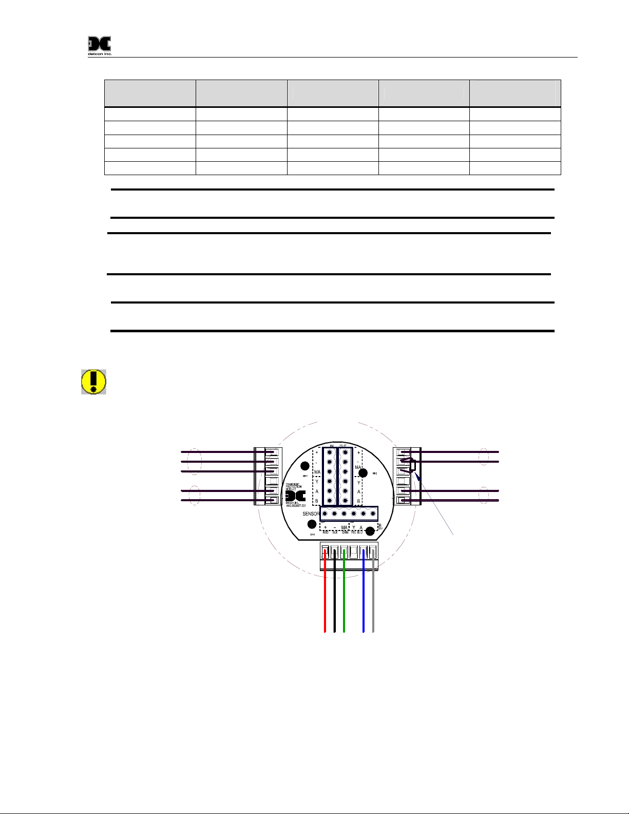
Figure 9 Sensor Wire Connections
a) Remove the junction box cover. Identify the terminal blocks for customer wire connections.
b) Observing correct polarity, terminate the 3-conductor 4-20mA field wiring (+, -, mA) to the sensor
assembly wiring in accordance with the detail shown in Figure 9. If the 4-20mA output is not used,
install a 100-250Ω resistor between the mA and (-) terminals on the Transient Protection Module.
PI-700 Instruction Manual Rev. 2.5 Page 9 of 54
Page 14

Model PI-700
NOTE
NOTE
NOTE
NOTE
: If the 4-20mA output is not being used, a 100-250Ω resistor must be installed between
the mA and (-) terminals on the Transient Protection Module to ensure RS-485 communication
is not disrupted by a 4-20mA Fault.
a) If applicable, terminate the RS-485 serial wiring as shown in Figure 9. Use the second plug (Out) as
termination point on the customer side to facilitate a continuous RS-485 serial loop
The RS-485 (if applicable) requires 24 gauge, two conductor, shielded, twisted pair cable between the sensor
and host. General Cable Commodore part number ZO16P0022189 is recommended.
: Install a 120-ohm resistor across A & B terminals on the last sensor in the serial loop.
c) Trim all exposed wire leads if they are not permanently landed in the terminal block.
d) Replace the junction box cover.
2.7 Initial Start Up
Upon completion of all mechanical mounting and termination of all field wiring, apply system power in the
range of 11.5-30VDC (24VDC typical) and observe the following normal conditions:
a) PI-700 display reads close to “0”, and no fault messages are flashing.
b) A temporary upscale or downscale reading may occur as the sensor stabilizes. This upscale reading will
typically decrease to near “0”ppm within 1-2 minutes of power-up, assuming there is no gas in the area of
the sensor. In some extreme cases, the sensor may require up to 5 minutes before the lamp ignites and
becomes operational.
: The 4-20mA signal is held constant at 4mA for the first two minutes after power up.
Initial Operational Tests
After a warm up period of 1 hour (or when zero has stabilized), the sensor should be checked to verify
sensitivity to the specific target gas of the application (not just Isobutylene span gas).
: A secondary filter accessory, built into the splashguard adapter, is used with the Model
700 PID sensors (Figure 14). This multi-stage filter is designed to prevent heavy and complex
airborne VOC molecules from contacting the PID sensor and causing surface contamination
and subsequent reading drift. When used effectively, it may extend the time between required
sensor cleaning and / or sensor replacement. Its use is limited to application cases where the
target gas(s) are moderate to small VOC molecules (i.e. benzene and smaller molecular
weights). Before installing, it must be verified that the filter does not inhibit response to the
target gas being monitored. Do not use this filter if the target gas response is inhibited. The
service life of the filter may vary depending on the application; however, it is advised to
change it out at least on a 18-24 month cycle.
Material Requirements
Detcon PN 613-120000-700 700 Series Splash Guard with integral Cal Port -OR-
Detcon PN 943-000006-132 Threaded Calibration Adapter
PI-700 Instruction Manual Rev. 2.5 Page 10 of 54
Page 15

Model PI-700
Detcon Span Gas (See Detcon for Ordering Information). Recommended span gas is 50% of range
with Isobutylene in air or N2balance.
Detcon P/N 985-241100-321 In-Line Humidifying Tube 24"
a) Attach the calibration adapter to the threaded sensor housing or connect tubing to integral cal port. Apply
the test gas at a controlled flow rate of 200 - 500cc/min using the in-line humidifying tube, (200cc/min is
the recommended flow). Observe that the ITM display increases to a level near that of the applied
calibration gas value.
b) Remove test gas and observe that the ITM display decreases to “0”.
Initial operational tests are complete. PI-700 VOC gas sensors are factory calibrated prior to shipment, and
should not require significant adjustment on start up. However, it is recommended that a complete calibration
test and adjustment be performed 16 to 24 hours after power-up. Refer to zero and span calibration
instructions in Section 3.4.
PI-700 Instruction Manual Rev. 2.5 Page 11 of 54
Page 16
Model PI-700
NOTE
3. Operation
3.1 Programming Magnet Operating Instructions
The Operator Interface of the Model 700 Series gas sensors is accomplished via two internal magnetic
switches located to either side of the LED display (see Figure 11). The two switches, labeled “PGM1” and
“PGM2”, allow for complete calibration and configuration, thereby eliminating the need for area declassification or the use of hot permits.
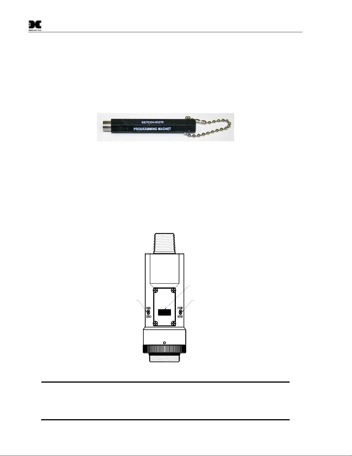
Figure 10 Magnetic Programming Tool
The magnetic programming tool (Figure 10) is used to operate the magnetic switches. Switch action is defined
as momentary contact, 3-second hold, and 10-second hold. (Hold times are defined as the time from the point
when the arrow-prompt “◄“appears.) For momentary contact use, the programming magnet is briefly held
over a switch location. For 3-second hold, the programming magnet is held in place over the switch location
for three seconds. For 10-second hold, the programming magnet is held in place over the switch location for
10 seconds. The 3 and 10 second holds are generally used to enter calibration/program menus and save new
data. The momentary contact is generally used to move between menu items and to modify set-point values.
Arrows (“◄” and “►”) are used on the LED display to indicate when the magnetic switches are activated.
The location of “PGM1” and “PGM2” are shown in Figure 11.
LED Display
Program Switch #2
Program Switch #1
detcon inc.
detcon inc.
MODEL
PI-700
VOC
Figure 11 Magnetic Programming Switches
: While in the Program Mode, if there is no magnetic switch interaction after 4
consecutive menu scrolls, the sensor will automatically revert to normal operating condition.
While changing values inside menu items, if there is no magnet activity after 3-4 seconds
the sensor will revert to the menu scroll.
(Exception to this is with “Signal Output Check” mode.)
PI-700 Instruction Manual Rev. 2.5 Page 12 of 54
Page 17

Model PI-700
3.2 Operator Interface
The operating interface is menu-driven via the two magnetic program switches located under the target marks
of the sensor housing. The two switches are referred to as “PGM1” and “PGM2”. The menu list consists of
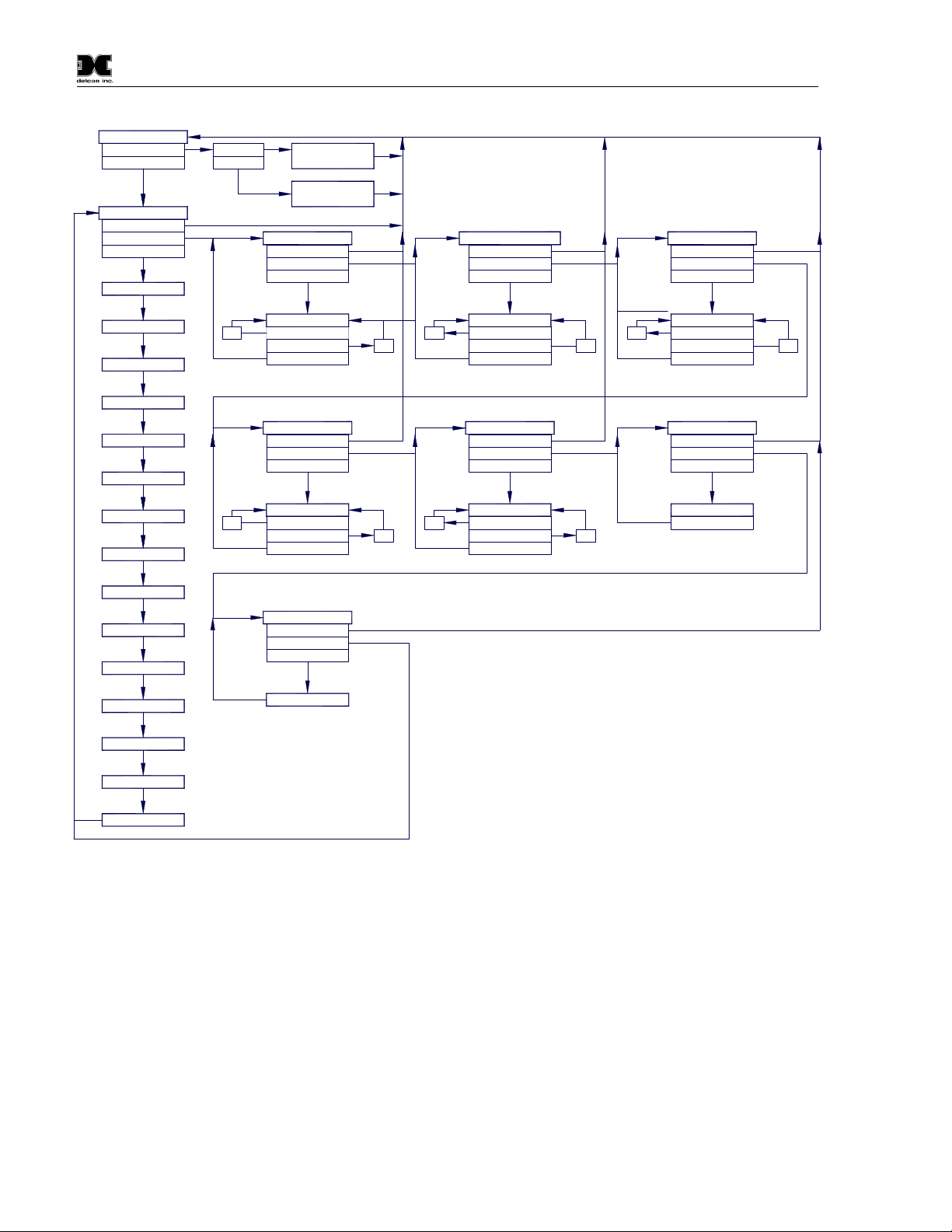
three major items that include sub-menus as indicated below. (Refer to the complete Software Flow Chart.)
Normal Operation
Current Reading and Gas Type/Fault Status
Calibration Mode
AutoZero
AutoSpan
Program Mode
View Sensor Status
Sensor Model Type
Current Software Version
Gas Type
Range of Detection
Serial ID address
AutoSpan Level
Days Since Last AutoSpan
Remaining Sensor Life
Gas Factor
Zero Offset
mA Output
Input Voltage Supply
Sensor Temperature
Gain Setting
Raw Counts
Set AutoSpan Level
Set Serial ID
Set Range
Set Gas Factor
Set Zero Offset
Signal Output Check
Restore Default Settings
PI-700 Instruction Manual Rev. 2.5 Page 13 of 54
Page 18
Normal Operation
PGM1 (3)
PGM2 (10)
View Sensor Status
Auto Time-Out
PGM1/2 (M)
PGM1/2 (3)
Model Type
PGM1 (3)
PGM2 (3)
AutoZero
AutoSpan
Set AutoSpan Level
AutoTime-out
PGM1/2 (M)
PGM1/2 (3)
Software Flowchart
Set Serial ID
Auto Time-Out
PGM1/2 (M)
PGM1/2 (3)
Set Range
Auto Time-Out
PGM1/2 (M)
PGM1/2 (3)
Model PI-700
Version X.XX
Gas Type
Range XXX
Serial ID XX
AutoSpan @ XX
Last Cal XX Days
Sensor Life XXX%
Gas Factor = XX
Zero Offset = X.X
mA Output = XX.XX
Input Volt = XX.XX
Temperature = XXX
Gain Setting = XXX
Raw Counts = XXX
inc
inc
##
PGM2 (S)
PGM1 (S)
PGM1/2 (3)
Set Gas Factor
Auto Time-Out
PGM1/2 (M)
PGM1/2 (3)
##
PGM2 (S)
PGM1 (S)
PGM1/2 (3)
Restore Defaults
Auto Time-Out
PGM1/2 (M)
PGM2 (10)
Defaults Restored
dec
dec
##
inc
inc
PGM2 (S)
PGM1 (S)
PGM1/2 (3)
Set Zero Offset
Auto Time-Out
PGM1/2 (M)
PGM1/2 (3)
##
PGM2 (S)
PGM1 (S)
PGM1/2 (3)
dec
dec
LEGEND:
PGM1 - Program Switch Location #1
PGM2 - Program Switch Location #2
(S) - Momentary Swipe
(M) - Momentary hold of Magnet during text
scroll until the ">" appears, then release
(3) - 3 second hold from ">" prompt
(10) - 10 second hold from ">" prompt
Auto Time-out - 5 seconds
inc - Increase
dec - Decrease
X, XX, XXX - numeric values
inc
##
PGM2 (S)
PGM1 (S)
PGM1/2 (3)
Signal Output Check
Auto Time-Out
PGM1/2 (M)
PGM1/2 (10)
Simulation
PGM1/2 (3)
dec
Figure 12 PI-700 Software Flowchart
3.3 Normal Operation
In normal operation, the ITM Display continuously shows the current sensor reading, which will normally
appear as “ 0 ”. Once every 60 seconds the LED display will flash the sensor’s measurement units and gas
type (i.e. ppm VOC). If the sensor is actively experiencing any diagnostic faults, a “Fault Detected” message
will scroll across the display on the ITM display once every minute instead of the units of measure and the gas
type. At any time, while the sensor is in “Fault Detected” mode, PGM1 or PGM2 can be swiped to prompt the
sensor to display a list of the active faults.
In normal operation, the 4-20mA current output linearity corresponds with the full-scale range. The RS-485
Modbus™ serial output provides the current gas reading and complete fault status on a continuous basis when
polled by the master device.
PI-700 Instruction Manual Rev. 2.5 Page 14 of 54
Page 19

Model PI-700
NOTE:
NOTE:
NOTE:
3.4 Calibration Mode
3.4.1 AutoZero
The AutoZero function is used to zero the sensor. Local ambient air can be used to zero calibrate a VOC gas
sensor as long as it can be confirmed that it contains no target or interference gasses. If this cannot be
confirmed then a zero air or N2cylinder should be used.
Material Requirements:
Detcon PN 327-000000-000 MicroSafe™ Programming Magnet
Detcon PN 613-120000-700 700 Series Splash Guard with integral Cal Port and Calibration Wind
Guard (P/N 943-000000-000) -OR-
Detcon PN 943-000006-132 Threaded Calibration Adapter
Detcon PN 942-001123-000 Zero Air cal gas (or use ambient air if no target gas is present).
Detcon P/N 942-640023-100 Nitrogen 99.99%
Detcon P/N 985-241100-321 In-Line Humidifying Tube 24"
The Calibration Wind Guard must be used when the Splashguard Adapter with
integral Cal Port is used. Failure to use the Calibration Wind Guard may result in an inaccurate
AutoZero calibration.
a) For VOC sensors, if the ambient air is known to contain no target gas content, then it can be used for zero
calibration. If a zero gas or N2cal cylinder is going to be used, be sure to use in-line humidifying tube to
present cal gas with correct ambient humidity level. Attach the calibration adapter and set flow rate of
200-500cc/min and let sensor purge for 1-2 minutes before executing the AutoZero.
b) From Normal Operation, enter Calibration Mode by holding the programming magnet over PGM1 for 3
seconds. Note, the “◄” prompt will show that the magnetic switch is activated during the 3 second hold
period. The display will then scroll “PGM1=AutoZero …PGM2=AutoSpan”. Hold the programming
magnet over PGM1 for 3 seconds once the “►” prompt appears to execute AutoZero (or allow to timeout
in 5 seconds if AutoZero is not desired).
Upon entering Calibration Mode, the 4-20mA signal drops to 2mA and is held at this
level until the program returns to normal operation. Modbus™ Status Register bit 14 is also set
to signify when the sensor is in-calibration mode.
c) The ITM will display the following sequence of text messages as it proceeds through the AutoZero
sequence:
Zero Cal . . . Setting Zero . . . Zero Saved
a) Remove the zero gas and calibration adapter, if applicable.
3.4.2 AutoSpan
The AutoSpan function is used to span calibrate the sensor. Unless otherwise specified, span adjustment is
recommended at 50% of range. This function is called “AUTO SPAN”.
Before performing AutoSpan Calibration, verify that the AutoSpan level matches the
span calibration gas concentration as described in Section 3.5.2 Set AutoSpan Level.
PI-700 Instruction Manual Rev. 2.5 Page 15 of 54
Page 20

Model PI-700
NOTE 1:
NOTE 2:
NOTE 3:
NOTE 4:
NOTE 5:
Material Requirements:
Detcon PN 327-000000-000 MicroSafe™ Programming Magnet
Detcon PN 613-120000-700 700 Series Splash Guard with integral Cal Port and Calibration Wind
Guard (P/N 943-000000-000) - OR -
Detcon PN 943-000006-132 Threaded Calibration Adapter
Target Span Gas (See Detcon for Ordering Information) representing the target gas (with air or N
balance) between 10% and 90% of the full-scale range - OR -
Isobutylene Span Gas. Recommended span gas is 50% of range with Isobutylene in air or N2balance
Detcon P/N 985-241100-321 In-Line Humidifying Tube 24"
Contact Detcon for Ordering Information on Span Gas cylinders.
For span, an Isobutylene gas concentration of 50% of range is normally
recommended (see Note 4). This should be supplied at a controlled flow rate of 500cc/min
using the in-line humidifying tube. Other concentrations can be used if they fall within
allowable levels of 5% to 100% of range.
If Isobutylene is used as span gas, the correct Gas Factor must be used.
It is strongly recommended to use the target VOC gas to calibrate for span. This
eliminates any possibility that Isobutylene cross-calibration is not accurate. Cross-calibration
by use of other gasses should be confirmed by Detcon or at a minimum executed relative to the
information provided in Table 5.
The Calibration Wind Guard must be used when the Splashguard Adapter with
integral Cal Port is used. Failure to use the Calibration Wind Guard may result in an inaccurate
AutoSpan calibration.
2
CAUTION: Verification that the calibration gas level setting matches the calibration span gas
concentration is required before executing “AutoSpan” calibration. These two numbers must be equal.
AutoSpan consists of entering Calibration Mode and following the menu-displayed instructions. The display
will ask for the application of span gas in a specific concentration. The applied gas concentration must be
equal to the calibration gas level setting. The factory default setting and recommendation for span gas
concentration is 50% of range. If a span gas containing the recommended concentration is not available, other
concentrations may be used as long as they fall between 5% and 100% of range. However, any alternate span
gas concentration value must be programmed via the “Set AutoSpan Level” menu before proceeding with
AutoSpan calibration. Follow the instructions “a” through “e” below for AutoSpan calibration.
a) Verify that the AutoSpan Level is equal to the Calibration Span Gas Concentration. (Refer to View
Sensor Status in Section 3.5.1.) If the AutoSpan Level is not equal to the Calibration span gas
concentration, adjust the AutoSpan Level as instructed in Section 3.5.2 Set AutoSpan Level.
b) From Normal Operation, enter Calibration Mode by holding the programming magnet over PGM1 for 3
seconds. Note, the “◄” prompt will show that the magnetic switch is activated during the 3 second hold
period. The display will then scroll “PGM1=AutoZero . . . PGM2=AutoSpan”. Hold the programming
PI-700 Instruction Manual Rev. 2.5 Page 16 of 54
Page 21

Model PI-700
NOTE:
NOTE:
NOTE 1
NOTE 2
“Range Fault”
NOTE 3
“Stability Fault”
magnet over PGM2 for 3 seconds to execute AutoSpan (or allow to timeout in 5 seconds if AutoSpan is
not intended). The ITM will then scroll “Apply XX ppm Gas”.
Upon entering Calibration Mode, the 4-20mA signal drops to 2mA and is held at this
level until the program returns to normal operation. Modbus™ Status Register bit 14 is also set
to signify when the sensor is in-calibration mode.
c) Apply the span calibration test gas for VOC gas sensors at a flow rate of 200-500cc/min using the in-line
humidifying tube (200cc/min is recommended). As the sensor signal begins to increase the display will
switch to flashing “XX“reading as the ITM shows the sensor’s “as found” response to the span gas
presented. If it fails to meet the minimum in-range signal change criteria within 2½ minutes, the display
will report “Range Fault” twice and the ITM will return to normal operation, aborting the AutoSpan
sequence. The ITM will continue to report a “Range Fault” and will not clear the fault until a successful
AutoSpan is completed.
Assuming acceptable sensor signal change, after 1 minute the reading will auto-adjust to the programmed
AutoSpan level. During the next 30 seconds, the AutoSpan sequence checks the sensor for acceptable reading
stability. If the sensor fails the stability check, the reading is re-adjusted back to the AutoSpan level and the
cycle repeats until the stability check is passed. Up to three additional 30-second stability check periods are
allowed before the unit reports a “Stability Fault” twice and the ITM will return to normal operation, aborting
the AutoSpan sequence. The ITM will continue to report a “Stability Fault” and will not clear the fault until a
successful AutoSpan is completed.
If the sensor passes the stability check, the ITM reports a series of messages:
“Span OK”
“Sensor Life XXX%”
“Remove Span Gas”
d) Remove the span gas source and calibration adapter. The ITM will report a live reading as it clears toward
“0”. When the reading clears below 10% of range, the ITM will display “Span Complete” and will revert
to normal operation. If the sensor fails to clear to less than 10% in less than 5 minutes, a “Clearing Fault”
will be reported twice and the ITM will return to normal operation, aborting the AutoSpan sequence. The
ITM will continue to report a “Clearing Fault” and will not clear the fault until a successful AutoSpan is
completed.
When calibrating sensors where there are high levels of VOC gases in the ambient
background, use Zero Air or N2to assist clearing to <10% of range.
e) The AutoSpan calibration is complete.
: Upon entering the calibration menu, the 4-20mA signal drops to 2mA and is held at
this level until the program returns to normal operation.
: If the sensor fails the minimum signal change criteria, a
will be
declared and a “Fault Detected” message will be displayed alternately with the sensor’s
current reading. The 4-20mA output will be taken to 0mA and the ‘Range Fault’ fault bit will
be set on the Modbus™ output.
: If the sensor fails the stability criteria, a
will be declared and a
“Fault Detected” message will be displayed alternately with the sensor’s current reading. The
4-20mA output will be taken to 0mA and the ‘Stability Fault’ fault bit will be set on the
Modbus™ output.
PI-700 Instruction Manual Rev. 2.5 Page 17 of 54
Page 22

Model PI-700
NOTE 4
Clearing Fault
: If the sensor fails the clearing time criteria, a “
” will be declared and a
“Fault Detected” message will be displayed alternately with the sensor’s current reading. The
4-20mA output will be taken to 0mA and the ‘Clearing Fault’ fault bit will be set on the
Modbus™ output.
3.5 Program Mode
Program Mode provides a “View Sensor Status” menu to check operational and configuration parameters.
Program Mode provides for adjustment of the AutoSpan Level, Serial ID, Set Range, Set Gas Factor, and Set
Zero Offset. Additionally, Program Mode includes the diagnostic function “Signal Output Check” and
“Restore Factory Defaults”.
The Program Mode menu items appear in the order presented below:
View Sensor Status
Set AutoSpan Level
Set Serial ID
Set Range
Set Gas Factor
Set Zero Offset
Signal Output Check
Restore Default Settings
Navigating Program Mode
From Normal Operation, enter Program Mode by holding the magnet over PGM2 for 10 seconds. Note, the
“◄” prompt will show that the magnetic switch is activated during the 10 second hold period. The ITM will
enter Program Mode and the display will display the first menu item “View Sensor Status”. To advance to the
next menu item, hold the magnet over PGM1 or PGM2 while the current menu item’s text is scrolling. At the
conclusion of the text scroll the arrow prompt (“◄” for PGM2 or “►” for PGM1) will appear, immediately
remove the magnet. The ITM will advance to the next menu item. Repeat this process until the desired menu
item is displayed. Note, PGM1 moves the menu items from right to left and PGM2 moves the menu items
from left to right.
To enter a menu item, hold the magnet over PGM1 or PGM2 while the menu item is scrolling. At the
conclusion of the text scroll the “◄”prompt (“◄” for PGM2 or “►” for PGM1) will appear, continue to hold
the magnet over PGM1 or PGM2 for an additional 3-4 seconds to enter the selected menu item. If there is no
magnet activity while the menu item text is scrolling (typically 4 repeated text scrolls), the ITM will
automatically revert to Normal Operation.
3.5.1 View Sensor Status
View Sensor Status displays all current configuration and operational parameters including: sensor type,
software version number, gas type, detection range, AutoSpan level, days since last AutoSpan, estimated
remaining sensor life, gas factor, zero offset, mA output, input voltage, sensor ambient temperature, gain
setting, and the sensor’s raw counts.
From the View Sensor Status text scroll, hold the magnet over PGM1 or PGM2 until the “◄” prompt appears
and continue to hold the magnet in place for an additional 3-4 seconds (until the display starts to scroll “Status
Is”). The display will scroll the complete list of sensor status parameters sequentially:
PI-700 Instruction Manual Rev. 2.5 Page 18 of 54
Page 23

Sensor Model Type
The menu item appears as: “Model PI-700”
Current Software Version
The menu item appears as: “Version 1.XX”
Gas Type
The menu item appears as: “ Gas Type = VOC”
Range of Detection.
The menu item appears as: “Range XXX”
Serial ID address.
The menu item appears as: “Serial ID XX”
AutoSpan Level.
The menu item appears as: “AutoSpan Level XX”
Model PI-700
Days Since Last AutoSpan.
The menu items appears as: “Last Cal XX days”
Remaining Sensor Life.
The menu item appears as: “Sensor Life 100%”
Gas Factor
The menu item appears as: “Gas Factor X.X”
Zero Offset
The menu item appears as: “Zero Offset X.X”
mA Output
The menu item appears as: “mA Output XX.XX”
Input Voltage Supply
The menu item appears as: “Voltage XX.X VDC”
Sensor Temperature
The menu item appears as: “Temp XX C”
Gain Setting
The menu item appears as: “Gain XX”
Raw Counts
The menu item appears as: “Counts XXXX”
PI-700 Instruction Manual Rev. 2.5 Page 19 of 54
Page 24

Model PI-700
When the status list sequence is complete, the ITM will revert to the “View Sensor Status” text scroll. The
user can either: 1) review list again by executing another 3-4 second hold, 2) move to another menu item by
executing a momentary hold over PGM1 or PGM2, or 3) return to Normal Operation via automatic timeout of
about 15 seconds (the display will scroll “View Sensor Status” 4 times and then return to Normal Operation).
3.5.2 Set AutoSpan Level
Set AutoSpan Level is used to set the span gas concentration level that is being used to calibrate the sensor.
This level is adjustable from 1% to 99% of range depending on the range of the sensor (see Table 2) . The
current setting can be viewed in View Program Status.
Table 2 Maximum and Minimum AutoSpan Settings
Sensor
Full Scale
Range
1.00 0.01 0.99 0.01 95 1 90 Note 1
2.00 0.01 1.99 0.01 100 1 95 Note 1
3.00 0.01 2.99 0.01 150 1 100 Note 1
4.00 0.01 3.99 0.01 200 1 150 Note 1
5.00 0.01 4.99 0.01 250 1 200 Note 1
6.00 0.01 5.99 0.01 300 1 250 Note 1
7.00 0.01 6.99 0.01 350 1 300 Note 1
8.00 0.01 7.99 0.01 400 1 350 Note 1
9.00 0.01 8.99 0.01 450 1 400 Note 1
10.0 1.0 9.9 0.1 500 1 450 Note 1
11.0 1.0 10.9 0.1 550 1 500 Note 1
12.0 1.0 11.9 0.1 600 1 550 Note 1
13.0 1.0 12.9 0.1 650 1 600 Note 1
14.0 1.0 13.9 0.1 700 1 650 Note 1
15.0 1.0 14.9 0.1 750 1 700 Note 1
16.0 1.0 15.9 0.1 800 1 750 Note 1
17.0 1.0 16.9 0.1 850 1 800 Note 1
18.0 1.0 17.9 0.1 900 1 850 Note 1
19.0 1.0 18.9 0.1 950 1 900 Note 1
20.0 1.0 19.9 0.1 1000 1 950 Note 1
21.0 1.0 20.9 0.1 1500 1 1000 Note 1
22.0 1.0 21.9 0.1 2000 1 1500 Note 1
23.0 1.0 22.9 0.1 2500 1 2000 Note 1
24.0 1.0 23.9 0.1 3000 1 2500 Note 1
25.0 1.0 24.9 0.1 3500 1 3000 Note 1
30 1 25 Note 1 4000 1 3500 Note 1
35 1 30 Note 1 4500 1 4000 Note 1
40 1 35 Note 1 5000 1 4500 Note 1
45 1 40 Note 1 5500 1 5000 Note 1
50 1 45 Note 1 6000 1 5500 Note 1
55 1 50 Note 1 6500 1 6000 Note 1
60 1 55 Note 1 7000 1 6500 Note 1
65 1 60 Note 1 7500 1 7000 Note 1
70 1 65 Note 1 8000 1 7500 Note 1
75 1 70 Note 1 8500 1 8000 Note 1
80 1 75 Note 1 9000 1 8500 Note 1
85 1 80 Note 1 9500 1 9000 Note 1
90 1 85 Note 1 10000 1 9500 Note 1
Note 1: When the AutoSpan value is between 1 and 25, the adjustment increment is 1
Minimum
AutoSpan
Level
When the AutoSpan value is between 26 and 100, the adjustment increment is 5
Maximum
AutoSpan
Level
Adjustment
Increment
Sensor
Full Scale
Range
Minimum
AutoSpan
Level
Maximum
AutoSpan
Level
Adjustment
Increment
PI-700 Instruction Manual Rev. 2.5 Page 20 of 54
Page 25

Model PI-700
When the AutoSpan value is between 101 and 1000, the adjustment increment is 50
When the AutoSpan value is between 1001 and 10000, the adjustment increment is 500
The menu item appears as: “Set AutoSpan Level”.
From the Set AutoSpan Level text scroll, hold the magnet over PGM1 or PGM2 until the “◄” prompt
appears and continue to hold the magnet in place for an additional 3-4 seconds (until the display starts to scroll
“Set Level”). The display will switch to “ XX“ (where XX is the current gas level). Swipe the magnet
momentarily over PGM2 to increase or PGM1 to decrease the AutoSpan Level until the correct level is
displayed. When the correct level is achieved, hold the magnet over PGM1 or PGM2 for 3-4 seconds to
accept the new value. The display will scroll “Level Saved”, and revert to “Set AutoSpan Level” text scroll.
Move to another menu item by executing a momentary hold, or return to Normal Operation via automatic
timeout of about 15 seconds (the display will scroll “Set AutoSpan Level” 4 times and then return to Normal
Operation).
3.5.3 Set Serial ID
Detcon Model PI-700 sensors can be polled serially via RS-485 Modbus™ RTU. Refer to Section 4.0 for
details on using the Modbus™ output feature.
Set Serial ID is used to set the Modbus™ serial ID address. It is adjustable from 01 to 256 in hexadecimal
format (01-FF hex). The current serial ID can be viewed in View Sensor Status using the instruction given in
Section 3.5.1 View Sensor Status.
The menu item appears as: “Set Serial ID”.
From the “Set Serial ID” text scroll, hold the programming magnet over PGM1 or PGM2 until the “◄”
prompt appears and continue to hold the magnet in place for an additional 3-4 seconds (until the display starts
to scroll “Set ID”). The display will then switch to “ XX“ (where XX is the current ID address). Swipe the
magnet momentarily over PGM2 to increase or PGM1 to decrease the hexadecimal number until the desired
ID is displayed. Hold the magnet over PGM1 or PGM2 for 3-4 seconds to accept the new value. The display
will scroll “ID Saved”, and revert to “Set Serial ID” text scroll.
Move to another menu item by executing a momentary hold, or, return to Normal Operation via automatic
timeout of about 15 seconds (the display will scroll “Set Serial ID” 5 times and then return to Normal
Operation).
3.5.4 Set Range
The full-scale range of a PI-700 sensor is determined at the time of order. The Intelligent Plug-in Sensor is
factory calibrated for this range. However, if the application requirements change and the user needs to alter
the original range, the “Set Range” function can be used to make field adjustments.
The currently selected full-scale range is displayed in the “View Sensor Status” menu. The factory calibrated
full-scale range is printed on the Intelligent Plug-in Sensor Label. When a new range is selected the 4-20mA
and Modbus™ outputs will automatically be rescaled, and the span gas level will default to 50% of the new
range.
The menu item appears as: “Set Range”
From the “Set Range” text scroll, hold the programming magnet over PGM1 or PGM2 until the “◄” prompt
appears and continue to hold the magnet in place for an additional 3-4 seconds (until the display starts to scroll
PI-700 Instruction Manual Rev. 2.5 Page 21 of 54
Page 26

Model PI-700
NOTE1:
calibrated after any change is made to the sensor range.
NOTE2:
“Set Range”). The display will then switch to “XXX“(where XXX is the current Range). Swipe the magnet
momentarily over PGM2 to increase or PGM1 to decrease the range Level until the desired range is displayed.
Hold the magnet over PGM1 or PGM2 for 3 seconds to accept the new value. The display will scroll “Range
Saved”, and revert to “Set Range” text scroll.
Selectable ranges are:
1, 2, 3, 4, 5, 6, 7, 8, 9, 10, 15, 20 – Normal ranges for Low Range Sensors.
25, 30, 35, 40, 45, 50, 55, 60, 65, 70, 75, 80, 85, 90, 100, 150, 200, 250, 300, 350, 400, 450, 500, 600, 700,
800, 900, 1000, 2000, 3000, 4000, 5000 – Normal ranges for High Range Sensors.
The PI-700 ITM output range can be changed from the plug-in intelligent PID sensor range, but only within
the following limitations: The range can be lowered by a factor of 4, or increased by a factor of 4. It is
possible, but not advisable, to take a sensor outside the normal ranges for the sensor. Taking a sensor out of
the normal range limits for that sensor may give unreliable, inconsistent results, and should be avoided.
Move to another menu item by executing a momentary hold, or, return to Normal Operation via automatic
timeout of about 15 seconds (the display will scroll “Set Range” 4 times and then return to Normal Operation).
The sensor should be re-
AutoSpan and AutoZero should be re-established.
When a new plug-in sensor is installed, the ITM will automatically default to the
range of the plug-in sensor.
3.5.5 Set Gas Factor
All span calibrations are recommended to be done with a calibration standard consisting of Isobutylene in air
background. If the target gas is not Isobutylene the correct Gas Factor will need to be set for correct operation.
Refer to Table 5 for the correct Gas Factor for the target gas. The current Gas Factor is displayed in the “View
Sensor Status” menu.
The menu item appears as: “Set Gas Factor”
From the Set Gas Factor text scroll, hold the magnet over PGM1 or PGM2 until the “◄” prompt appears and
continue to hold the magnet in place for an additional 3-4 seconds (until the display starts to scroll “Set
Factor”). The display will then switch to “ X.XX“ (where X.XX is the current gas factor). Swipe the magnet
momentarily over PGM2 to increase or PGM1 to decrease the gas factor level until the correct value is
displayed. Hold the magnet over PGM1 or PGM2 for 3 seconds to accept the new value. The display will
scroll “Factor Saved”, and revert to “Set Gas Factor” text scroll.
Move to another menu item by executing a momentary hold, or, return to Normal Operation via automatic
timeout of about 15 seconds (the display will scroll “Set Gas Factor” 4 times and then return to Normal
Operation.
3.5.6 Set Zero Offset
If it is determined that there is a constant but negligible amount of residual active VOC gases in the
background air, the Zero Offset feature can optionally be used to null this reading out.
To set the “Zero Offset” of the sensor, observe the sensor’s concentration reading after a ‘true’ zero air
calibration procedure. This reading represents the background ambient VOC contribution to the sensors actual
zero set point. Record this reading to set the Zero Offset.
PI-700 Instruction Manual Rev. 2.5 Page 22 of 54
Page 27

Model PI-700
NOTE
NOTE
The menu item appears as: “Set Zero Offset”
From the “Set Zero Offset” text scroll, hold the programming magnet over PGM1 or PGM2 until the “◄”
prompt appears and then hold continue to hold the magnet in place for an additional 3-4 seconds (until the
display starts to scroll “Set Zero Offset”). The display will then switch to “ X.X“ (where X.X is the current
offset). Swipe the magnet momentarily over PGM2 to increase or PGM1 to decrease the number until the
desired zero offset is displayed. Hold the magnet over PGM1 or PGM2 for 3-4 seconds to accept the new
value. The display will scroll “ID Saved”, and revert to “Set Zero Offset” text scroll.
Move to another menu item by executing a momentary hold, or, return to Normal Operation via automatic
timeout of about 15 seconds (the display will scroll “Set Zero Offset” 5 times and then return to Normal
Operation).
If performed correctly the sensor should read 0.0 after returning to normal operation.
3.5.7 Signal Output Check
Signal Output Check provides a simulated 4-20mA output and RS-485 Modbus™ output. This simulation
allows the user to conveniently perform a functional system check of their entire safety system. This signal
output simulation also aids the user in performing troubleshooting of signal wiring problems.
The menu item appears as: “Signal Output Check”.
From the “Signal Output Check” text scroll, hold the magnet over PGM1 or PGM2 until the “◄” prompt
appears and then hold continuously for an additional 10 seconds. Once initiated, the display will scroll
“Simulation Active” until the function is stopped. During simulation mode, the 4-20mA value will be
increased from 4.0mA to 20.0mA (in 1% of range increments at about a 1 second update rate) and then
decreased from 20.0mA to 4.0mA. The same simulation sequence is applied to the Modbus™ output gas
reading.
: Signal Output Check stays active indefinitely until the user stops the function. There
is no automatic timeout for this feature.
To end simulation mode, hold magnet over PGM1 or PGM2 for 3 seconds. The display will either move to the
prior menu item or move to the next menu item respectively.
Move to another menu item by executing a momentary hold, or, return to Normal Operation via automatic
timeout of about 15 seconds.
3.5.8 Restore Factory Defaults
Restore Factory Defaults is used to clear current user configuration and calibration data from memory and
revert to factory default values. This may be required if the settings have been configured improperly and a
known reference point needs to be re-established to correct the problem.
This menu item appears as: “Restore Defaults”.
: Restoring factory defaults should only be used when absolutely necessary. All
previously existing configuration inputs will have to be re-entered if this function is executed.
A full 10-second magnet hold on PGM 2 is required to execute this function.
PI-700 Instruction Manual Rev. 2.5 Page 23 of 54
Page 28

Model PI-700
NOTE
From the “Restore Defaults” text scroll, hold the programming magnet over PGM2 until the “◄” prompt
appears and continue to hold 10 seconds. The display will scroll “Restoring Defaults”, followed by “New
ECS Connected”, and “Range XX” where XX is the default range of the intelligent plug-in sensor.
Move to another menu item by executing a momentary hold, or, return to Normal Operation via automatic
timeout of about 15 seconds (the display will scroll “Restore Defaults” 4 times and then return to Normal
Operation).
Following the execution of “Restore Defaults”, the PI-700 will revert to its factory default settings. The
default settings are:
Serial ID = 01. The Serial ID must be set appropriately by the operator (Section 3.5.3).
: The following must be performed in order before the sensor can be placed in operation.
AutoSpan Level = 50% of range. AutoSpan level must be set appropriately by the operator (Section 3.5.2).
Range: Defaults to range of intelligent plug-in sensor, must be set to the appropriate level by the operator
(Section 3.5.4).
AutoZero: AutoZero settings are lost and user must perform new AutoZero (Section 3.4).
AutoSpan: AutoSpan Settings are lost and user must perform new AutoSpan (Section 3.4).
3.6 Program Features
Detcon PI-700 toxic gas sensors incorporate a comprehensive set of diagnostic features to achieve Fail-Safe
Operation. These Operational features and Failsafe Diagnostic features are detailed below.
3.6.1 Operational Features
Over-Range
When gas greater than the full-scale range is detected, the ITM display will continuously flash the full-scale
reading. This designates an over-range condition. The 4-20mA signal will report a 22mA output during this
time.
In-Calibration Status
When the sensor is engaged in AutoZero or AutoSpan calibrations, the 4-20 mA output signal is taken to 2.0
mA and the in-calibration Modbus™ register bit is set. This alerts the user that the ITM is not in an active
measurement mode. This feature also allows the user to log the AutoZero and AutoSpan events via their
master control system.
Sensor Life
Sensor Life is calculated after each AutoSpan calibration and is reported as an indicator of remaining service
life. It is reported in the “View Sensor Status” menu and as a RS-485 Modbus™ register bit. Sensor Life is
reported on a scale of 0-100%. When Sensor Life falls below 25%, the sensor cell should be cleaned or
replaced within a reasonable maintenance schedule.
Last AutoSpan Date
This reports the number of days that have elapsed since the last successful AutoSpan. This is reported in the
View Sensor Status menu. After 180 days, an AutoSpan Fault will be declared.
PI-700 Instruction Manual Rev. 2.5 Page 24 of 54
Page 29

Model PI-700
NOTE
3.6.2 Fault Diagnostic/Failsafe Features
Fail-Safe/Fault Supervision
Model PI-700 sensors are designed for Fail-Safe operation. If any of the diagnostic faults listed below are
active, the ITM Display will scroll the message “Fault Detected” every 1 minute during normal operation. At
any time during “Fault Detected” mode, holding the programming magnet over PGM1 or PGM2 for 1 second
will display the active fault(s). All active faults are reported sequentially.
Most fault conditions result in failed operation of the sensor. In these cases the 4-20mA signal is dropped to
the universal fault level of 0mA. These include the AutoSpan Calibration faults, Sensor Fault, Processor Fault,
Memory Fault, Loop Fault, and Input Voltage Fault. The 0mA fault level is not employed for Temperature or
AutoSpan Faults. For every diagnostic fault condition the associated RS-485 Modbus™ fault register will be
flagged to alert the user digitally.
: Refer to the Troubleshooting Guide section for guidance on how to address fault
conditions.
Range Fault – AutoSpan
If the sensor fails the minimum signal change criteria (Section 3.4.2) during AutoSpan sequence, the “Range
Fault” will be declared. A “Range Fault” will cause a “Fault Detected” message to flash intermittently on the
ITM display and drop the 4-20mA output to 0mA. The Modbus™ fault register bit for Range Fault will be set
and will not clear until the fault condition has been cleared. The sensor should be considered ‘Out-of-Service’
until a successful AutoSpan calibration is performed.
Stability Fault - AutoSpan
If the sensor fails the signal stability criteria (Section 3.4.2) during AutoSpan sequence, the “Stability Fault”
will be declared. A “Stability Fault” will cause a “Fault Detected” message to flash intermittently on the ITM
display and drop the mA output to 0mA. The Modbus™ fault register bit for Stability Fault will be set and
will not clear until the fault condition has been cleared. The sensor should be considered as ‘Out-of-Service’
until a successful AutoSpan calibration is performed.
Clearing Fault - AutoSpan
If the sensor fails the signal stability criteria (Section 3.4.2) during AutoSpan sequence, the “Clearing Fault”
will be declared. A “Clearing Fault” will cause a “Fault Detected” message to flash intermittently on the ITM
display and drop the mA output to 0mA. The Modbus™ fault register bit for Clearing Fault will be set and
will not clear until the fault condition has been cleared. The sensor should be considered as ‘Out-of-Service’
until a successful AutoSpan calibration is performed.
Zero Fault
If the sensor drifts to < -10% of range, an “Under-Range Fault” will be declared. An “Under-Range Fault”
will cause a “Fault Detected” message to flash intermittently on the ITM display. The Modbus™ fault register
bit for Under-Range Fault will be set and will not clear until the fault condition has been cleared. If an UnderRange Fault occurs, the 4-20mA signal will be set at 0mA until the fault condition is resolved.
Sensor Fault
If the intelligent plug-in sensor is not plugged in, plugged in incorrectly, or there is a communication failure, a
“Sensor Fault” is declared. A “Sensor Fault” will cause a “Fault Detected” message to flash intermittently on
the ITM display. The Modbus™ fault register bit for Sensor Fault will be set and will not clear until the fault
PI-700 Instruction Manual Rev. 2.5 Page 25 of 54
Page 30

Model PI-700
condition has been cleared. If a Sensor Fault occurs, the 4-20mA signal will be set at 0mA until the fault
condition is resolved.
Processor Fault
If the detector has any unrecoverable run-time errors, a “Processor Fault” is declared. A “Processor Fault”
will cause a “Fault Detected” message to flash intermittently on the ITM display. The Modbus™ fault register
bit for Processor Fault will be set and will not clear until the fault condition has been cleared. If a Processor
Fault occurs, the 4-20mA signal will be set at 0mA until the fault condition is resolved.
Memory Fault
If the detector has a failure in saving new data to memory, a “Memory Fault” is declared. A “Memory Fault”
will cause the “Fault Detected” message to flash intermittently on the ITM display. The Modbus™ fault
register bit for Memory Fault will be set and will not clear until the fault condition has been cleared. If a
Memory Fault occurs, the 4-20mA signal will be set at 0mA until the fault condition is resolved.
4-20mA Loop Fault
If the sensor detects a condition where the 4-20mA output loop is not functional (high loop resistance or failed
circuit function) a “4-20mA Fault” is declared. A “4-20mA Fault” will cause the “Fault Detected” message to
scroll once a minute on the ITM display. The Modbus™ fault register bit for Loop Fault will be set and will
not clear until the fault condition has been cleared. If a Loop Fault occurs, the 4-20mA signal will be set at
0mA until the fault condition is resolved. If the 4-20mA current loop is still out of tolerance, contact Detcon
at [email protected], or contact Detcon customer service.
Input Voltage Fault
If the detector is currently receiving an input voltage that is outside of the 11.5-28VDC range, an “Input
Voltage Fault” is declared. An “Input Voltage Fault” will cause the “Fault Detected” message to flash
intermittently on the ITM display. The fault register bit for Input Voltage Fault will be set and will not clear
until the fault condition has been cleared. If an Input Voltage Fault occurs, the 4-20mA signal will be set at
0mA until the fault condition is resolved.
Temperature Fault
If the detector is currently reporting an ambient temperature that is outside of the –40C° to +75C° range a
“Temperature Fault” is declared. A “Temperature Fault” will cause the “Fault Detected” message to flash
intermittently on the ITM display. The Modbus™ fault register bit for Temperature Fault will be set and will
not clear until the fault condition has been cleared. If a Temperature Fault occurs, the 4-20mA signal remains
operational.
AutoSpan Fault
If 180 days has elapsed since the last successful AutoSpan, an AutoSpan Fault will be generated. An
“AutoSpan Fault” will cause the “Fault Detected” message to flash intermittently on the ITM display. The
Modbus™ fault register bit for AutoSpan Fault will be set and will not clear until the fault condition has been
cleared by executing a successful AutoSpan. If an AutoSpan occurs, the 4-20mA signal remains operational.
PI-700 Instruction Manual Rev. 2.5 Page 26 of 54
Page 31

Model PI-700
3,2
40003
4,2
5
4. RS-485 Modbus™ Protocol
Model DM-700 sensors feature Modbus™ compatible communications protocol and are addressable via the
program mode. Other protocols are available. Contact the Detcon factory for specific protocol requirements.
Communication is two wire, half duplex 485, 9600 baud, 8 data bits, 1 stop bit, no parity, with the sensor set
up as a slave device. A master controller up to 4000 feet away can theoretically poll up to 256 different
sensors. This number may not be realistic in harsh environments where noise and/or wiring conditions would
make it impractical to place so many devices on the same pair of wires. If a multi-point system is being
utilized, each sensor should be set for a different address. Typical address settings are: 01, 02, 03, 04, 05, 06,
07, 08, 09, 0A, 0B, 0C, 0D, 0E, 0F, 10, 11…etc.
Sensor RS-485 ID numbers are factory default to 01. These can be changed in the field via the Operator
Interface described in Section 3.5.5 Set Serial ID.
The following section explains the details of the Modbus™ protocol that the DM-700 sensor supports.
Code 03 - Read Holding Registers is the only code supported by the transmitter. Each transmitter contains 6
holding registers which reflect its current status.
Table 3 Modbus™ Registers
FC REG Content Description R/W Content Definition
03 40000 Device Type R 8 700 Sensor
030640001
40001
03 40002 Read Concentration
030640003
03 40004 Read Sensor Life R 85 For 85% sensor life
03 40005 Read Fault Status Bits
03 40006 Read Model # R 1, 2, 3, 4, 5 DM, FP, IR, TP, PID
03 40007 Read Days Since Cal R 29 29days
03 40008 4-20 Current Output
03 40009 Read Input Voltage
03 40010 Read Temperature R 28 28 °C
03/0640011 Special #1 R/W Function dependent on value of
Read Detectable
Write Detectable Range
Read AutoSpan Level
Write AutoSpan Level
Range
mA x100
V x100
1,2
R/W 100
R 1000 Bound by range. If > range, this
R/W 50 Span gas at 50 DM – 1% to 95% of Range (40001)
R 0x0001
R 400 4.00mA
R 2400 24.00V
Value Meaning Range
10000
0x0002
0x0004
0x0008
0x0010
0x0020
0x0040
0x0080
0x0100
0x0200
0x0400
0x0800
0x1000
0x2000
0x4000
0x8000
For 0-100
For 0-10000
value is in fault.
Global Fault
Auto Span Fault
Temperature Fault
4-20mA Fault
Input Voltage Fault
Memory Fault
Processor Fault
Clearing Fault
Stability Fault
Range Fault
Sensor Fault
Zero Fault
Sensor Fault 2
<reserved>
In Calibration
Communication Error
respectively
40006 (See Special Register
2
Table 4)
DM – 0 to 10000
FP – Read only
TP – 20, 50, 100, 200
IR – 0 to 10000
PI – 0 to 10000
FP – 5% to 95% of Range (40001)
TP – 2% to 50% of Range (40001)
IR – 5% to 95% of Range (40001)
PI – 1% to 95% of Range (40001)
Range
PI-700 Instruction Manual Rev. 2.5 Page 27 of 54
Page 32
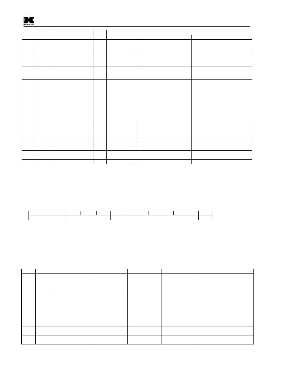
Model PI-700
6
6
6
6
6
6
1
(R/W)
(R/W)
(R/W)
FC REG Content Description R/W Content Definition
Value Meaning Range
03/0640012 Special #2 R/W Function dependent on value of
40006 (See Special Register
Table 4)
03 40013 Special #3 R Function dependent on value of
40006 (See Special Register
Table 4)
03/0640014 Special #4 R/W Function defendant on value of
40006 (See Special Register
Table 4)
030640015
40015
Calibration Status
Calibration Enable
RW0x0000
0x0001
0x0002
0x0003
0x0004
0x0001
0x0002
0x0008
0x0009
0x000A
0x000B
Idle
Zero Calibration Started
Span Calibration Started
Span Set
Span Calibration Unsuccessful
Set Zero
Set Span
Signal simulation mode
Set FP Bridge Voltage
Set TP Heater Power
Set IR Gain
03 40016 Read Text 1, first char inLR Two Char of Gas/Units String
03 40017 Read Text 2 R Two Char of Gas/Units String
03 40018 Read Text 3 R Two Char of Gas/Units String
03 40019 Read Text 4 R Two Char of Gas/Units String
03 40020 Read Text 5, last char inHR Two Char of Gas/Units String
03 40021 Text null terminator in L R Two Char of Gas/Units String
1
Integer ranges from 1 all the way to 10,000.
2
Units are determined by “units” field in the “notation” string
3
Gas Reading times one (x 1) with units in notation string for “Low Range” = 0. Gas Reading times one (x 10) with units in notation string for “Low
Range” = 1. Gas Reading times one (x 100) with units in notation string for “Low Range” = 2.
4
Span Gas must be less than or equal to Detectable Range and is usually about ½ of it.
5
Fault status bits self-reset when fault clears
6
Text in ASCII, in order L byte, H byte, L byte… See field descriptions of notation string.
Gas/Units String
Character # 1 2 3 4 5 6 7 8 9 10 11
Description Units 0x20 Gas Type 0x00
Units – This field is ‘PPM’, ‘PPB’, or ‘_ _ %’ (where ‘ _ ‘ is a space, 0x20).
0x20 – The units filed is terminated with an ASCII space (0x20)
Gas Type – This field contains the gas type of the cell. Any ASCII string is permissible
0x00 – The notation string is terminated with an ASCII null character
Table 4 Modbus™ Special Registers
REG DM (40006 = 1) FP (40006 = 2) IR(40006 = 3) TP (40006 = 4)
40011 Low Range= 0, 1, 2
0: Range >25 (0 decimal place)
1: Range 10-25 (1 decimal place)
2: Range <10 (2 decimal place)
40012 0x8XXX
0x0XXX
0xX000
0xX096
0xX0C8
0xX12C
Positive Polarity Cell
Negative Polarity Cell
Bias = 0mV
Bias = 150mV
Bias = 200mV
Bias = 300mV
40013 Gain Code
(integer between 0 & 15)
40014 Raw Counts 0-0xFFFF
1
Only possible ranges are 20, 50, 100, 200. Modbus register 40001 will contain either 20, 50, 100, or 200, range divisor is not necessary.
(0x8000 = nominal 0)
Gas Factor
Range = 79 to 565
Cal Factor
Range = 79 to 565
Gas Factor
Range = 20 to 565
Heater Power
(mW) (R/W)
Active Counts Heater Voltage
(mV)
Bridge Current (mA) Reference Counts Sensor Resistance
(x100 Ω)
Bridge Voltage (mV)
(Read only)
Range Divisor
1,10,100, or 1000
Heater Current
(mA )
Low Range= 0, 1, 2
0: Range >25
1: Range 10-25
2: Range <10
0x8XXX
0x0XXX
0xX000
0xX096
0xX0C8
0xX12C
Gain Code
Raw Counts
PI (40006 = 5)
Positive Polarity
Cell
Negative Polarity
Cell
Bias = 0mV
Bias = 150mV
Bias = 200mV
Bias = 300mV
PI-700 Instruction Manual Rev. 2.5 Page 28 of 54
Page 33
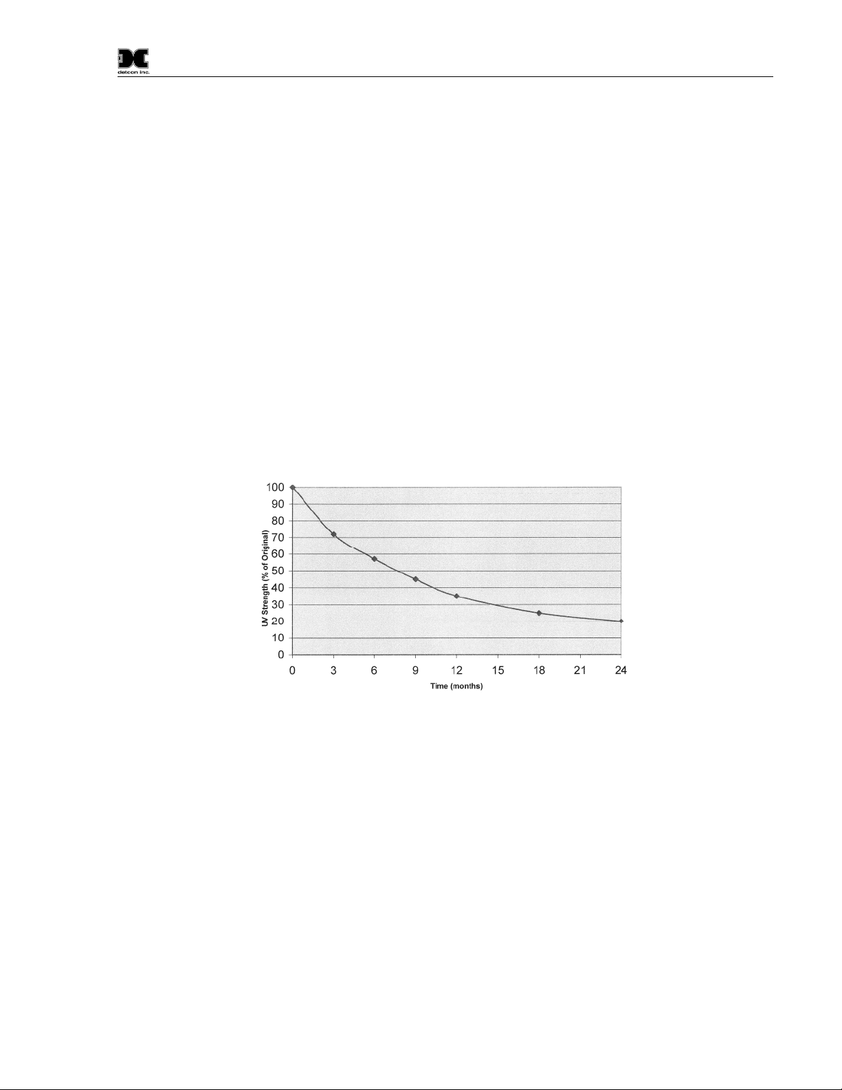
Model PI-700
5. Service and Maintenance
Calibration Frequency
In most applications, quarterly span calibration intervals will assure reliable detection. However, industrial
environments differ. Upon initial installation and commissioning, close frequency tests should be performed,
weekly to monthly. Test results should be recorded and reviewed to determine a suitable calibration interval.
If, after 180 days, an Auto-Span Calibration is not performed, the ITM will generate an AutoSpan Fault.
5.1 PID Plug-In Sensor Maintenance
The plug-in PID Sensor will need to be properly maintained to achieve proper long-term performance. All
PID sensors use a UV lamp that has a finite lifetime. The Detcon PID UV lamp source is expected to last at
least 1 year. However, from the time of installation a gradual loss in UV lamp strength is expected (Figure
13). As the UV lamp strength decreases the sensor signal will decrease accordingly. This dictates that
periodic span calibrations are required to maintain calibration accuracy. To determine the present signal
strength of the PID sensor execute a valid span calibration and view the Sensor Life from the ‘View Program
Status’ menu. Any Sensor Life value less than 30% should result in the user’s choice of replacing the plug-in
sensor, cleaning the UV Lamp, or replacing the UV Lamp.
Figure 13 UV Lamp Aging Expectation
If the PID sensor appears to be losing signal strength at a rate faster than the estimates shown in Figure 13, the
sensor is most likely experiencing contamination film build-up on the UV optical filter. This will happen
when exposed to certain gases or ambient contaminations that collect on the surface of the UV filter. The
result is a decrease in the amount of emitted UV light from the lamp source. This is known to happen with
gases that can be polymerized by UV light (such as heavy complex VOC’s), airborne oil vapors, and very fine
dust. As UV Filter contamination occurs, the sensor’s signal strength falls off in addition to the expected loss
rate shown in Figure 13. This phenomenon can be reversed by disassembling the sensor and carefully cleaning
the UV lamp filter using a specialized cloth.
A secondary filter accessory, built into the splashguard adapter, is used with the Model 700 PID sensors
(Figure 14). This multi-stage filter is designed to prevent heavy and complex airborne VOC molecules from
contacting the PID sensor and causing surface contamination and subsequent reading drift. When used
effectively, it may extend the time between required sensor cleaning and / or sensor replacement. Its use is
limited to application cases where the target gas(s) are moderate to small VOC molecules (i.e. benzene and
smaller molecular weights). Before installing, it must be verified that the filter does not inhibit response to the
target gas being monitored. Do not use this filter if the target gas response is inhibited. The service life of the
PI-700 Instruction Manual Rev. 2.5 Page 29 of 54
Page 34
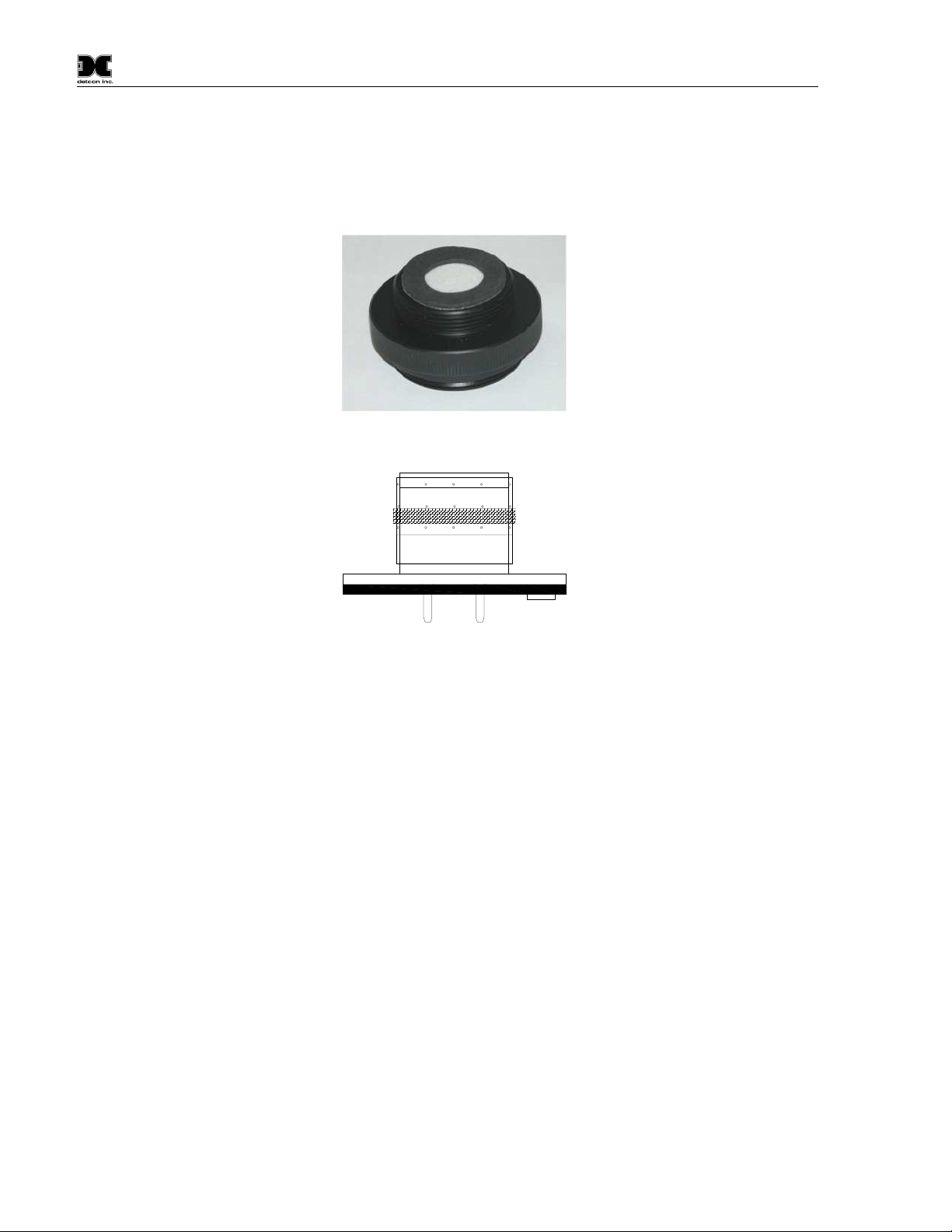
Model PI-700
filter may vary depending on the application; however, it is advised to change it out at least on a 18-24 month
cycle.
In addition, a small moisture control packet (P/N 960-700PID-000) Figure 15 is banded around the plug-in
PID sensor. This helps the sensor maintain better zero stability in extremely high humidity conditions. It is
only to be used in conjunction with the secondary filter discussed previously. This moisture control packet
should be replaced on an 18-24 month cycle.
Figure 14 Splashguard Adapter with Integral Filter
DetconP/N 960-700PID-000
Avoidcontactwith crystals
Figure 15 Plug-in sensor with Moisture control packet
It is also possible, under certain ambient contamination conditions, that the sensor’s Detector Cell may have a
partially conductive film that forms across the contact grids. This condition causes the zero background signal
to gradually increase to the point where it becomes unacceptable for the range of signal input to the transmitter
electronics. When this occurs the detector cell should be replaced. This can be checked by examining the
amount of raw signal that is produced during exposure to zero gas. Refer to the ‘View Program Status’ menu
and record the Raw Signal report after 5 minutes of zero gas exposure. A value that exceeds 3000 counts
would be evidence of this problem.
General recommendations for Sensor Maintenance
For normal environmental exposure and signal decay, replace the plug-in sensor every 9-12 months.
(especially if there are no skilled technicians to handle proper UV lamp replacement.)
If skilled technicians are available, replace just the UV lamp every 9-12 months.
For abnormally high rates of signal decay, clean the UV lamp monthly, using a Lamp Cleaning Kit, and
replace the UV lamp every 9-12 months.
For any proven cases where the zero baseline has drifted up, replace the detector cell.
PI-700 Instruction Manual Rev. 2.5 Page 30 of 54
Page 35
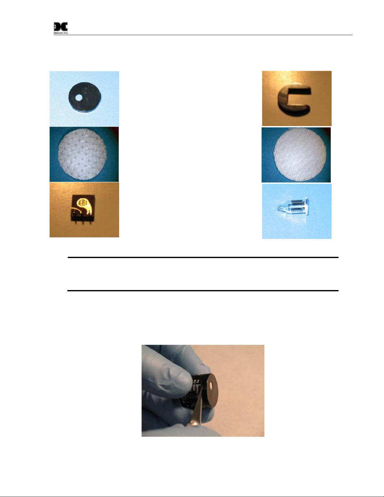
All piD Sensor Cells contain six user replaceable components:
NOTE
Filter Cap Spacer
Filter Media #1 Filter Media #2
Cell Assembly 10.6eV Lamp
Model PI-700
Figure 16 Sensor Cell Parts
: Avoid touching lamp’s window as well as any metal portion of the Detector Cell
with bare fingers. It is acceptable to hold the lamp by its glass body or by the edges of
the window. Fingerprints left on those parts may adversely affect the sensor’s
operation. Use of cotton or latex gloves is suggested.
Disassembly
1. Power down the instrument and remove the sensor cell.
2. Remove the filtercap by applying a slight upward pressure with the tip of a screwdriver or an Exacto Blade
just below the hole in the cap and between the cap and the housing.
Figure 17 Removal of Filter Cap
3. With a fine tipped tweezers, remove both the Filter Media and set aside.
PI-700 Instruction Manual Rev. 2.5 Page 31 of 54
Page 36
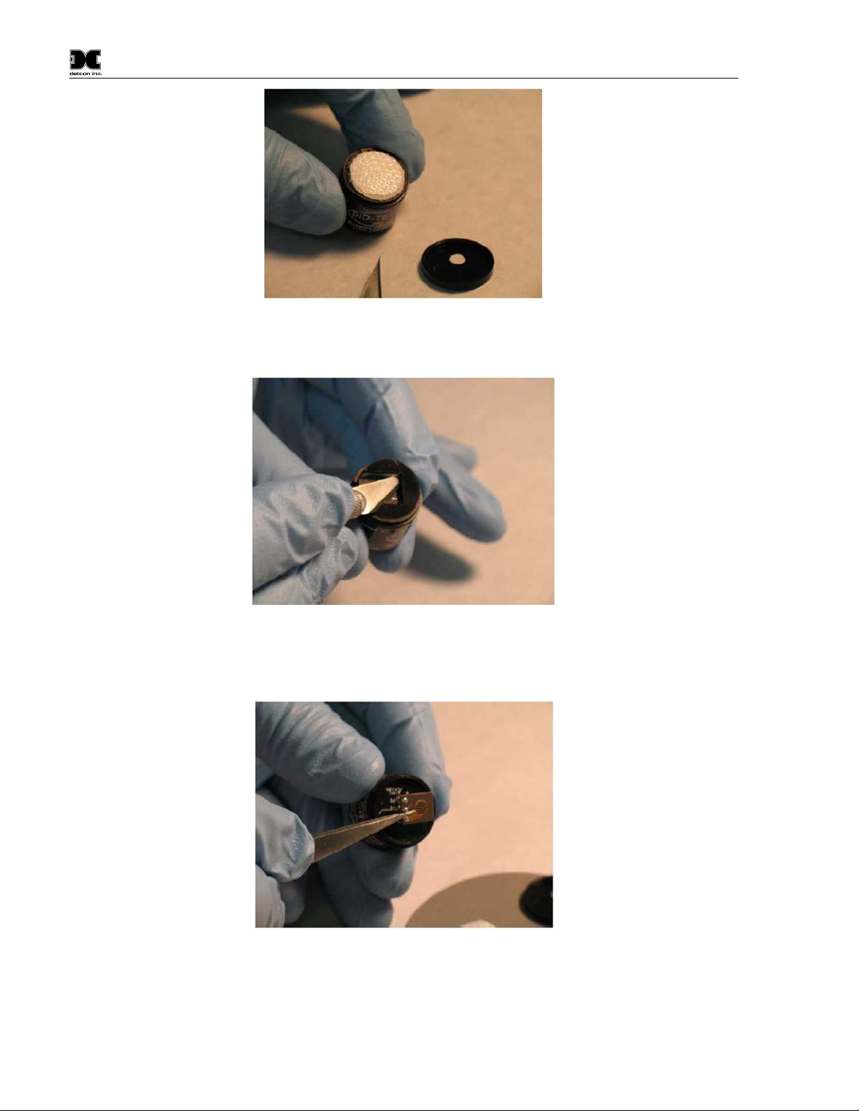
Figure 18 Removal of Filter Media
4. Using the Exacto Blade, remove the spacer and set it aside.
Model PI-700
Figure 19 Removal of Spacer
5. With fine tipped tweezers, carefully remove the cell assembly by prying under the cell’s edge where the
connector pins are located.
Figure 20 Removal of Cell Assembly
6. With fine tipped tweezers, grasp the lamp by placing the tips in the housing notch and gently pulling it out.
Be careful not to scratch the lamp lens or chip the edges.
PI-700 Instruction Manual Rev. 2.5 Page 32 of 54
Page 37
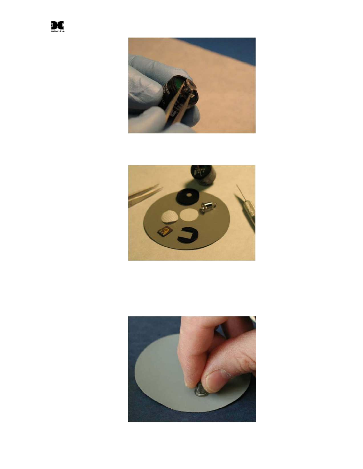
Cleaning the Lamp
Model PI-700
Figure 21 Removal of Lamp
Figure 22 Lamp cleaning
Wearing gloves grab the lamp by the cylindrical glass body and clean the window by rubbing it against the
Polishing Pad. Use a circular motion and try to keep the window surface flat relative to the pad. Five seconds
of rubbing should be enough in most cases. Another indication of cleaning completeness is that about 1/16thof
the pad surface is used during the process.
Figure 23 Polishing the Lamp
PI-700 Instruction Manual Rev. 2.5 Page 33 of 54
Page 38
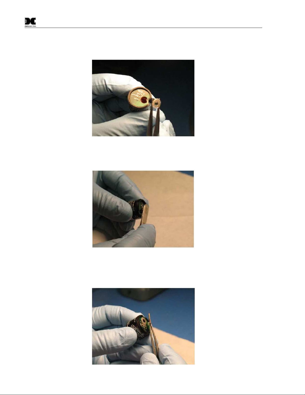
Model PI-700
Reassembly
1. Install the lamp into the sensor, making sure that the lamp’s metalized pads are aligned with the
corresponding excitation springs inside the lamp cavity
Figure 24 Lamp installation
2. With the end of the clean tweezers, or a clean blade of a screwdriver, press down firmly, being careful not
to scratch the surface of the lamp.
Figure 25 Lamp seating
3. Using fine tipped tweezers, install the cell assembly. Align the pins with the corresponding sockets on the
sensor and push down on the end with the pins. Make sure the cell assembly is flush with the lamp
window.
Figure 26 Cell Assembly installation
PI-700 Instruction Manual Rev. 2.5 Page 34 of 54
Page 39
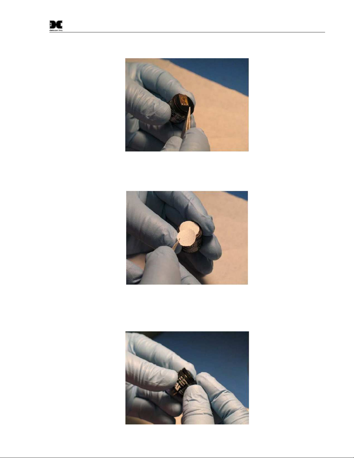
Model PI-700
4. Place the spacer around the assembly.
Figure 27 Spacer installation
5. Place the filter media over the Cell Assembly centered on the top of the sensor. Make sure the filters are
installed in the correct order. Filter Media #2 first, then Filter Media #1 on top, with the shiny side up.
Figure 28 Installing Filter Media
6. Align the Cap Key with the notch on the housing. Starting at the side opposite the notch, press down until
the Filter Cap snaps on to the housing. If the Cap Key is incorrectly aligned there will be a noticeable
bulge on the side of the cap.
Figure 29 Replacing the Cap
PI-700 Instruction Manual Rev. 2.5 Page 35 of 54
Page 40
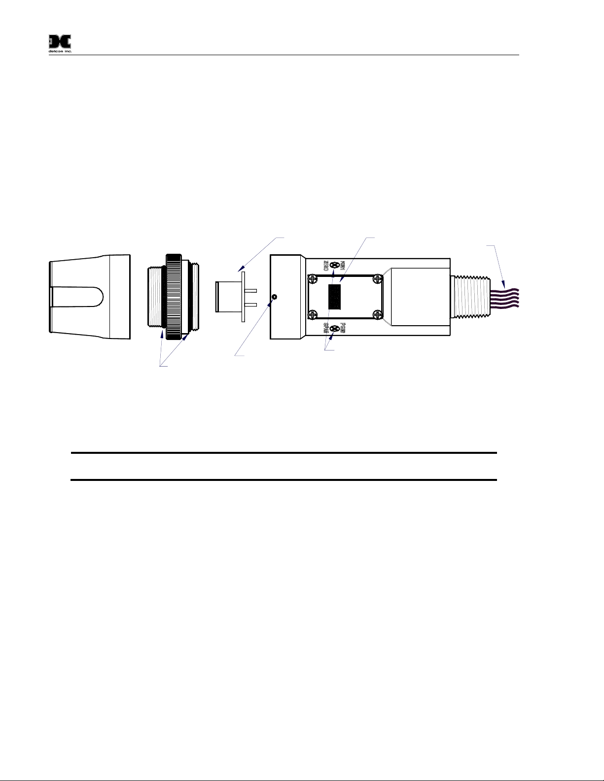
Model PI-700
NOTE
Visual Inspection
The Sensor should be inspected annually. Inspect for signs of corrosion, pitting, and water damage. During
visual inspection, the Splash Guard should be inspected to insure that it is not blocked. Examine the plug-in
sensor for signs of physical blockage, electrolyte leakage, or severe corrosion. Also, inspect inside the
Junction Box for signs of water accumulation or Terminal Block corrosion.
Condensation Prevention Packet
A moisture condensation packet should be installed in every explosion proof Junction Box. The moisture
condensation prevention packet will prevent the internal volume of the J-Box from condensing and
accumulating moisture due to day-night humidity changes. This packet provides a critical function and should
be replaced annually. Detcon’s PN is 960-202200-000.
Lens and LCD
Display
detcon inc.
MODEL
PI-700
Interconnect Wiring
Intelligent ransmitter Module (ITM)
Microprocessor controlled circuit
encapsulated in an explosion
proof housing
Splash Guard
Splashguard
Adapter
O-Rings
Plug-In replaceable
Sensor Cell
Housing Bottom
Locking Set-Screw
PI-700
VOC
detcon inc.
MODEL
Magnetic
Programming
Switches
Figure 30 Sensor Assembly
5.2 Replacement of Intelligent Plug-in Sensor
: It is not necessary to remove power while changing the Intelligent plug-in VOC gas
sensor in order to maintain area classification, since it is intrinsically safe.
a) Use a 1/16” Allen wrench to release the locking setscrew that locks the ITM and Splash Guard Adapter
together (One turn will suffice - Do not remove setscrew completely).
b) Remove splashguard. Unthread and remove the Splash Guard Adapter from the ITM.
c) Gently pull the plug-in sensor out of the ITM. Remove moisture control packet if supplied. Transfer to new
plug-in sensor. Orient the new plug-in sensor so that it matches with the female connector pins. When
properly aligned, press the sensor in firmly to make the proper connection.
PI-700 Instruction Manual Rev. 2.5 Page 36 of 54
Page 41

Model PI-700
NOTE
Locking Setscrew
Display Window
ITM
Bottom View
Plug-in Sensor
(Bottom View)
Figure 31 Sensor Cell and ITM Mating
d) Thread the Splash Guard Adapter onto the ITM to a snug fit and tighten the locking setscrew using the
1/16” Allen wrench. Reinstall the splashguard.
e) Verify the gas type and range of the new sensor by checking in View Program Status. It is recommended
“AutoZero and AutoSpan functions be performed, as per Section 3.4 Calibration Mode, to match the new
intelligent plug-in sensor with the ITM.
5.3 Replacement of ITM
a) Remove the power source from the sensor assembly. Disconnect all sensor wire connections at the J-Box
taking note of the wire connections.
: It is necessary to remove power to the J-Box while changing the ITM in order to
maintain area classification.
b) Use a wrench and the wrench flats provided at the top section of the ITM and unthread the ITM until it can
be removed.
c) Use a 1/16” Allen wrench to release the locking setscrew that locks the ITM and Splash Guard Adapter
together (One turn will suffice - Do not remove setscrew completely).
d) Remove splashguard. Unthread and remove the Splash Guard Adapter from the ITM.
e) Gently remove the plug-in gas sensor from the old ITM and install it in the new ITM. Orient the plug-in
sensor pins so that they match with the female connector sockets on the new ITM then press the sensor in
firmly to make proper connection.
f) Thread the Splash Guard Adapter onto the ITM until snug, tighten the locking setscrew and reconnect
splashguard.
g) Feed the sensor assembly wires through the ¾” female NPT mounting hole and thread the assembly into the
J-box until tight and the ITM lens faces toward the front access point. Connect the sensor assembly wires
inside J-Box (Refer to Section 2.6, and Figure 9).
h) Perform Set AutoSpan Level, Set Serial ID, Set Range, and then perform a successful AutoZero and
AutoSpan before placing sensor into service.
PI-700 Instruction Manual Rev. 2.5 Page 37 of 54
Page 42

Model PI-700
NOTE
5.4 Replacement of PI-700 Sensor Assembly
a) Remove the power source from the sensor assembly. Disconnect all sensor wire connections at the J-Box.
: It is necessary to remove power to the J-Box while changing the PI-700 sensor in order
to maintain area classification.
b) Use a wrench and the wrench flats provided at the top section of the ITM and unthread the ITM until it can
be removed.
c) Use a 1/16” Allen wrench to release the locking setscrew that locks the ITM and Splash Guard Adapter
together (One turn will suffice - Do not remove setscrew completely).
d) Remove splashguard. Unthread and remove the Splash Guard Adapter from the ITM.
e) Feed the new PI-700 sensor assembly wires through the ¾” female NPT mounting hole and thread the
assembly into the J-box until tight and the ITM lens faces toward the front access point. Connect the sensor
assembly wires inside J-Box (Refer to Section 2.6, and Figure 9).
f) PI-700 sensors are factory calibrated, however, they require an initial AutoZero and AutoSpan calibration
(Section 3.4), and must be configured per customer specific application requirements.
PI-700 Instruction Manual Rev. 2.5 Page 38 of 54
Page 43

Model PI-700
6. Troubleshooting Guide
Refer to the list of Failsafe Diagnostic features listed in Section 3.6.2 for additional reference in
troubleshooting activities. Listed below are some typical trouble conditions and their probable cause and
resolution path.
Locking Setscrew
Display Window
ITM
Bottom View
Plug-in Sensor
(Bottom View)
Figure 32 Sensor Cell and ITM Mating
Under-Range Fault
Probable Cause: Sensor Baseline drifted lower, Ambient Interference gasses reduced.
Repeat AutoZero. Use Zero Air or N2source.
Execute successful AutoSpan and verify adequate Sensor Life.
Check Raw counts in View Sensor Status. Count should be close to 1,500 for high range and 3,000
for low range.
Replace plug-in sensor if fault continues.
Missing Sensor Fault
Probable Cause: Sensor is Missing, Failed Plug-in Sensor Electronics, or ITM I.S. Barrier Failure.
Make sure plug-in sensor is plugged in properly with correct orientation.
Swap plug-in sensor into another ITM to determine if plug-in sensor problem or ITM problem.
Replace the plug-in sensor if proven faulty.
Replace the ITM if proven faulty.
AutoSpan Calibration Faults – (Range, Stability and Clearing)
To clear any AutoSpan Calibration fault, the AutoSpan process must be completed successfully (Section 3.4).
Use zero air gas after AutoSpan Calibration to avoid clearing fault from high background VOC levels.
Range Fault
Probable Causes: Failed Sensor, Cal Gas not applied or not applied at appropriate time, or problems w/ cal gas
and delivery.
Check validity of span gas (check MFG date on cal gas cylinder).
Use proper cal gas regulators and tubing for highly absorbing or corrosive gasses.
If using Splashguard with Integral Cal Port, must use Calibration Wind Guard or air movement can
compromise span gas delivery.
Check for obstructions affecting cal gas hitting sensor face (including being wet, blocked, or
corroded).
PI-700 Instruction Manual Rev. 2.5 Page 39 of 54
Page 44

Model PI-700
Verify adequate Sensor Life.
Clean or replace the PID lamp.
Replace the plug-in VOC sensor.
Stability Fault
Probable Causes: Failed Sensor, empty or close to empty Cal Gas Cylinder, or problems with cal gas and
delivery.
Check validity of span gas using pull tube or other means (check MFG date on cal gas cylinder).
Use proper cal gas regulators and tubing for highly corrosive gasses.
If using Splashguard with Integral Cal Port, must use Calibration Wind Guard or air movement can
compromise span gas delivery.
Check for obstructions affecting cal gas hitting sensor face (including being wet, blocked, or
corroded).
Verify adequate Sensor Life.
Clean or replace the PID lamp.
Replace the plug-in VOC sensor.
Clearing Fault
Probable Causes: Failed Sensor, Cal Gas not removed at appropriate time, problems with cal gas and delivery,
or background of Target Gas.
Must recover to < 5% of range in < 5 min after AutoSpan is complete.
Use bottled air (zero air or N2) if there is a known continuous background level.
Check validity of span gas using pull tube or other means (check MFG date on cal gas cylinder).
Use proper cal gas regulators and tubing for highly corrosive gasses.
Check for obstructions affecting cal gas hitting sensor face (including being wet, blocked, or
corroded).
Verify adequate Sensor Life.
Clean or replace the PID lamp.
Replace the plug-in VOC sensor.
Poor Calibration Repeatability
Probable Causes: Failed Sensor, use of wrong Cal Gas or problems with cal gas and delivery, or Interference
Gasses.
Check for adequate Sensor Life.
Check validity of span gas using pull tube or other means (check MFG date on cal gas cylinder).
Use proper cal gas regulators and tubing for highly corrosive gasses.
Check for obstructions affecting cal gas hitting sensor face (including being wet, blocked, or
corroded).
Verify adequate Sensor Life.
Clean or replace the PID lamp.
Replace the plug-in VOC sensor.
Unstable Output/ Sudden spiking
Possible Causes: Unstable power supply, inadequate grounding, or inadequate RFI protection.
Verify Power source is stable.
PI-700 Instruction Manual Rev. 2.5 Page 40 of 54
Page 45

Model PI-700
Verify field wiring is properly shielded and grounded.
Contact Detcon to optimize shielding and grounding.
Nuisance Alarms
Check condulet for accumulated water and abnormal corrosion on terminal blocks.
If nuisance alarms are happening at night suspect condensation in condulet.
Add or replace Detcon’s Condensation Prevention Packet P/N 960-202200-000.
Investigate the presence of other target gasses that are causing cross-interference signals.
Determine if cause is RFI induced.
Processor and/or Memory Faults
Recycle power in attempt to clear problem
Restore Factory Defaults - This will clear the processor’s memory and may correct problem.
Remember to re-enter all customer settings for range and cal gas level after Restore Factory Defaults.
If problem persists, replace the Intelligent Transmitter Module.
Unreadable Display
If due to excessive sunlight, install a sunshade to reduce glare.
Nothing Displayed – Transmitter not Responding
Verify condulet has no accumulated water or abnormal corrosion.
Verify required DC power is applied to correct terminals.
Swap with a known-good ITM to determine if ITM is faulty.
Faulty 4-20 mA Output
If Sensor has a normal reading with no Faults displayed, and the 4-20 mA signal output is 0mA….
Check that wiring is properly connected at terminal blocks and through to controller inputs.
The 4-20 output loop must be closed (resistance of < 1000 ohms) to avoid the Loop Fault.
Perform a “Signal Output Check” sequence via Section 3.5.7 and verify 4-20mA output with Current
Meter.
Swap with new ITM to determine if the ITM’s 4-20mA output circuit has failed.
If the 4-20mA current loop is still out of tolerance, contact Detcon at [email protected], or contact
Detcon customer service.
No Communication - RS-485 Modbus™
If sensor has a normal reading with no Faults displayed and the Modbus™ is not communicating….
Verify that the correct (and non-duplicated) serial address is entered (per Section 3.5.3).
Check that the wiring is properly connected at terminal blocks, and the serial loop is wired correctly.
Perform a “Signal Output Check” per Section 3.5.7 and troubleshoot wiring.
Consider adding a Modbus™ repeater if the distance from the nearest distribution drop is excessive.
Swap with new ITM to determine if the ITM’s serial output circuit is faulty.
Refer to Detcon’s “Guide to Proper Modbus™ Communications” Application Note.
PI-700 Instruction Manual Rev. 2.5 Page 41 of 54
Page 46

Model PI-700
7. Customer Support and Service Policy
Detcon Headquarters
Shipping Address: 4055 Technology Forest Blvd., The Woodlands Texas 77381
Mailing Address: P.O. Box 8067, The Woodlands Texas 77387-8067
Phone: 888.367.4286, or 281.367.4100
Fax: 281.292.2860
• www.detcon.com
All Technical Service and Repair activities should be handled by the Detcon Service Department via phone,
fax, or email at contact information given above. RMA numbers should be obtained from the Detcon Service
Department prior to equipment being returned. For on-line technical service, customers should have ready the
model number, part number, and serial number of product(s) in question.
All Sales activities (including spare parts purchase) should be handled by the Detcon Sales Department via
phone, fax or email at contact information given above.
Warranty Notice
Detcon Inc. warrants the Model PI-700 VOC gas sensors to be free from defects in workmanship and material
under normal use and service for two years from the date of shipment on the ITM electronics, and for the
conditional warranty period of twelve months on the intelligent plug-in sensor.
Detcon Inc. will repair or replace without charge any such equipment found to be defective during the
warranty period. Full determination of the nature of, and responsibility for, defective or damaged equipment
will be made by Detcon Inc. personnel.
Defective or damaged equipment must be shipped to the Detcon Inc. factory or representative from which the
original shipment was made. In all cases, this warranty is limited to the cost of the equipment supplied by
Detcon Inc. The customer will assume all liability for the misuse of this equipment by its employees or other
contracted personnel.
All warranties are contingent upon the proper use in the application for which the product was intended and
does not cover products which have been modified or repaired without Detcon Inc. approval, or which have
been subjected to neglect, accident, improper installation or application, or on which the original identification
marks have been removed or altered.
Except for the express warranty stated above, Detcon Inc. disclaims all warranties with regard to the products
sold. Including all implied warranties of merchantability and fitness and the express warranties stated herein
are in lieu of all obligations or liabilities on the part of Detcon Inc. for damages including, but not limited to,
consequential damages arising out of, or in connection with, the performance of the product.
PI-700 Instruction Manual Rev. 2.5 Page 42 of 54
Page 47

Model PI-700
NOTE
8. PI-700 Sensor Warranty
Intelligent Plug-in Sensor Warranty
Detcon Inc. warrants, under normal intended use, each new intelligent plug-in sensor for a period of twelve
months and under the conditions described as follows: The warranty period begins on the date of shipment to
the original purchaser. The sensor element is warranted to be free of defects in material and workmanship.
Should any sensor fail to perform in accordance with published specifications within the warranty period,
return the defective part to Detcon, Inc., 4055 Technology Forest Blvd., The Woodlands, Texas 77381, for
necessary repairs or replacement.
: The warranty only covers parts not working. This warranty does not cover conditions where the
detector cell or lamp may be dirty and can be restored by cleaning.
Terms & Conditions
* The original serial number must be legible on each sensor element base.
* Shipping point is FOB the Detcon factory.
* Net payment is due within 30 days of invoice.
* Detcon, Inc. reserves the right to refund the original purchase price in lieu of sensor replacement.
ITM Electronics Warranty
Detcon Inc. warrants, under intended normal use, each new Model 700 ITM to be free from defects in material
and workmanship for a period of two years from the date of shipment to the original purchaser. All warranties
and service policies are FOB the Detcon facility located in The Woodlands, Texas.
Terms & Conditions
* The original serial number must be legible on each ITM.
* Shipping point is FOB the Detcon factory.
* Net payment is due within 30 days of invoice.
* Detcon, Inc. reserves the right to refund the original purchase price in lieu of ITM replacement.
PI-700 Instruction Manual Rev. 2.5 Page 43 of 54
Page 48

Model PI-700
9. Appendix
9.1 Specifications
System Specifications
Sensor Type: Continuous diffusion/adsorption type
Photo Ionization Detector - PID
Plug-in Replaceable Intelligent Type (with replaceable Lamp)
Sensor Life: 2 years typical
Measuring Ranges: Gas Dependent, ranges as low as 0-10ppm or as high as 0-5,000ppm
(Consult Detcon) Special Low Range 0-500ppb
Accuracy/ Repeatability: ±10% of reading of full-range or ±2% of range (greater of)
Response Time: T50 <30 seconds; T90 < 60 seconds
Outputs: Linear 4-20mA DC
RS-485 Modbus™ RTU
Electrical Classification: Explosion Proof
CSA and US (NRTL)
Class I, Division 1, Groups B, C, D (Tamb=-40° to 75°C)
Class I, Zone I, Group IIB+H2
ATEX
EEx d IIB+H2T4 (Tamb=-40° tp 75°C)
Ingress Protection: NEMA 4X, IP66
Safety Approvals: cCSAus Performance to ISA 12.13.01-2000 and CSA 22.2 #152
ATEX
CE Marking
Warranty: Plug-in detector – 1 year
Transmitter – 2 years
Environmental Specifications
Operating Temperature: -4°F to +122°F; -20°C to +50°C
(Special -40°C version available)
Storage Temperature: --4°F to +122°F; -20°C to +50°C
Operating Humidity: 0-100% RH Non-Condensing
Mechanical Specifications
Dimensions 7"H x 2.2" Dia.; 178mmH x 65mm Dia. (sensor assembly only)
11"H x 6.1"W x 3.75"D; 280mmH x 155mmW x 96mmD (with junction box)
Mounting holes (J-box) 5.5"; 140mm center to center
PI-700 Instruction Manual Rev. 2.5 Page 44 of 54
Page 49

Model PI-700
Weight: 2 lbs; 0.907kg (sensor only)
6 lbs; 2.72kg (w/aluminum j-box)
9 lbs; 4.08kg (w/stainless steel j-box)
Electrical Specifications
Input Voltage: 11-30 VDC
Power Consumption: Normal operation = 68mA (<1.7 watt)
Maximum = 85mA (2 watts)
Inrush current: 1.67A @ 24V
RFI/EMI Protection: Complies with EN61000
Analog Output: Linear 4-20mA DC current (1000 ohms maximum loop load @ 24VDC)
0mA All Fault Diagnostics
2mA In-Calibration
4-20mA 0-100% full-scale
22mA Over-range condition
Serial Output: RS-485 Modbus™ RTU
Baud Rate: 9600 BPS (9600,N,8,1 Half Duplex)
Status Indicators: 4-digit LED Display with gas concentration
full-script menu prompts for AutoSpan,
Set-up Options, and Fault Reporting
Faults Monitored: Loop, Input Voltage,
Zero, Missing Sensor,
Processor, Memory, Calibration
Cable Requirements: Power/Analog: 3-wire shielded cable
Maximum distance is 13,300 feet with 14 AWG
Serial Output: 2-wire twisted-pair shielded cable specified for RS-485 use
Maximum distance is 4,000 feet to last sensor
I/O Protection: Over-Voltage, Miss-wiring, EMI/RFI Immunity
PI-700 Instruction Manual Rev. 2.5 Page 45 of 54
Page 50
Model PI-700
1
9.2 Gas Reference Table
Table 5 Gas Factor Table
Compound Name Synonym/Abbreviation Formula
Response
Factor
Acetaldehyde C2H4O 5.5 + 10.23 C25
Acetic Acid Ethanoic Acid C2H4O2 22 + 10.66 10
Acetic Anhydride Ethanoic Acid Anhydride C4H6O3 6.1 + 10.14 5
Acetone 2-Propanone C3H6O 1.1 + 9.71 500
Acetonitrile Methyl cyanide, Cyanomethane C2H3N NR 12.19 40
Acetylene Ethyne C2H2 NR 11.40 ne
Acrolein Propenal C3H4O 3.9 + 10.10 0.1
Acrylic Acid Propenoic Acid C3H4O2 12 + 10.60 2
Acrylonitrile Propenenitrile C3H3N NR + 10.91 2
Allyl alcohol C3H6O 2.4 + 9.67 2
Allyl chloride 3-Chloropropene C3H5Cl 4.3 9.9 1
Ammonia H3N 9.7 + 10.16 25
Amyl alcohol
mix of n-pentyl acetate &
2-Methylbutyl acetate
C5H12O 5 10.00 100
Aniline Aminobenzene C7H7N 0.5 + 7.72 2
Anisole Methoxybenzene C7H8O 0.8 8.21 ne
Arsine Arsenic trihydride AsH3 1.9 + 9.89 0.05
Benzaldehyde C7H6O ? 9.49 ne
Benzene C6H6 0.5 + 9.25 0.5
Benzonitrile Cyanobenzene C7H5N 1.6 9.62 ne
a-Hydroxytoluene,
Benzyl alcohol
Hydroxymethylbenzene,
C7H8O 1.1 + 8.26 ne
Benzenemethanol
Benzyl chloride
a-Chlorotoluene,
Chloromethylbenzene
C7H7Cl 0.6 + 9.14 1
Benzyl formate Formic acid benzyl ester C8H8O2 0.73 + ne
Boron trifluoride BF3 NR 15.5 C1
Bromine Br3 1.30 + 10.51 0.1
Bromobenzene C6H5Br 0.6 8.98 ne
2-Bromoethyl methyl ether C3H7OBr 0.84 + ~10 ne
Bromoform Tribromomethane CHBr3 2.5 + 10.48 0.5
Bromopropane, 1- n-Propyl bromide C3H7Br 1.5 + 10.18 ne
Butadiene 1,2-Butadiene, Vinyl ethylene C4H6 0.85 + 9.07 2
Butadiene diepoxide, 1, 3- 1,2,3,4-Diepoxybutane C4H6O2 3.5 + ~10 ne
Butane C4H10 67 10.53 ne
Butanol, 1- Butyl alcohol, n-Butanol C4H10O 4.7 + 9.99 C50
Butanol, t- tert-butanol, t-Buty alcohol C4H10O 2.9 + 9.90 100
Butene, 1- 1-Butylene C4H8 0.9 9.58 ne
Butoxyethanol, 2-
Butyl Cellosolve,
Ethyleneglycol monobutyl ether
C6H14O2 1.2 + <10 25
Butyl acetate, n- C6H12O2 2.6 + 10 150
Butyl acrylate, n-
Butyl 2-propenoate,
Acrylic acid butyl ester
C7H12O2 1.6 + 10
Butylamine, n- C4H11N 1.1 + 8.71 C5
Butyl cellosolve see 2-Butoxyethanol
Butyl hydroperoxide, t- C4H10O2 1.6 + <10 1
Butyl mercaptan 1-Butanethiol C4H10S 0.52 + 9.14 0.5
Confirmed
Value
IP (eV) TWA
1
NR = not recommended (does not register)
? = measurable but no data exist
Confirmed Value = “+” means actual gas has been used to verify RF, “blank” means it is an empirical estimate
IP = is the gases ionization potential (only gases < 10.6eV will respond to sensor)
TWA/Time Weighted Average = generally accepted limit for safe 8 hour exposure (in ppm)
ne = None Established
PI-700 Instruction Manual Rev. 2.5 Page 46 of 54
Page 51

Model PI-700
1
Compound Name Synonym/Abbreviation Formula
Carbon disulfide CS2 1.2 + 10.07 10
Carbon monoxide CO NR + 14.07 50
Carbon tetrachloride Tetrachloromethane CCl4 NR + 11.47 5
Carbonyl sulfide Carbon Oxysulfide COS NR 11.18
Cellosolve
(see 2-Ethoxyethanol)
CFC-14
(see Tetrafluoromethane)
CFC-113
(see 1,1,2-Trichloro-1,2,2-
trifluoroethane)
Chlorine Cl2 NR 11.48 0.5
Chlorine dioxide ClO2 NR + 10.57 0.1
Chloro-1,3-butadiene, 2- Chloroprene C4H5Cl 3 10
Chlorobenzene Monochlorobenzene C6H5Cl 0.40 + 9.06 10
Chloro-1, 1-difluoroethane,
1-(R-142B)
Chlorodifluoromethane HCFC-22, R-22 CHClF2 NR 12.2 1000
Chloroethane Ethyl chloride C2H5Cl NR + 10.97 100
Chloroethanol Ethylene chlorhydrin C2H5ClO 10.52 C1
Chloroethyl ether, 2- bis(2-chloroethyle) ether C4H8Cl2O 3.0 + 5
Chloroethyl methyl ether,2- Methyl 2-chloroethyl ether C3H7ClO 3 ne
Chloroform Trichloromethane CHCl3 NR + 11.37 10
Chloropicrin CCl3NO2 ~400 + ? 0.1
Chlorotoluene, o- o-Chloromethylbenzene C7H7Cl 0.5 8.83 50
Chlorotoluene, p- p-Chloromethylbenzene C7H7Cl 0.5 8.69 ne
Crotonaldehyde trans-2-Butenal C4H6O 1.1 + 9.73 2
Cumene Isopropylbenzene C9H12 0.54 + 8.73 50
Cyanogen bromide CNBr NR 11.84 ne
Cyanogen chloride CNCl NR 12.34 C0.3
Cyclohexane C6H12 1.4 + 9.86 300
Cyclohexanol Cyclohexyl alcohol C6H12O ? 9.75 50
Cyclohexanone C6H10O 0.9 + 9.14 25
Cyclohexene C6H10 0.8 + 8.95 300
Cyclohexylamine C6H13N 1.2 8.62 10
Cyclopentane C5H10 ? 10.51 600
Decane C10H22 1.4 + 9.65 ne
Diacetone alcohol 4-Methyl-4-hydroxy-2- pentanone C6H12O2 0.7 50
Dibromoethane,1,2-
Dichlorobenzene, o 1,2-Dichlorobenzene C6H4Cl2 0.47 + 9.08
Dichlorodifluoromethane CFC-12 CCl2F2 NR + 11.75 1000
Dichloroethane, 1,2Dichloroethene, 1,1- 1,1-DCE, Vinylidene chloride C2H2Cl2 0.9 9.79 5
Dichloroethene, c-1,2- c-1,2-DCE, cis-Dichloroethylene C2H2Cl2 0.8 9.66 200
Dichloroethene, t-1,2-
Dichloro-1-fluoroethane, 1,1- R-141B C2H3Cl2F NR + ne
Dichloromethane
(see Methylene chloride)
Dichloropentafluoropropane
Dichloropropane, 1,2 C3H6Cl2 NR 10.87 75
PI-700 Instruction Manual Rev. 2.5 Page 47 of 54
EDB, Ethylene dibromide,
Ethylene bromide
EDC, 1,2-DCA, Ethylene
dichloride
t-1,2-DCE, transDichloroethylene
AK-255, mix of ~45% 3,3-
dichloro-1,1,1,2,2-pentafluoro-
propane (HCFC-225ca) & ~55%
1,3-Dichloro-1,1,2,2,3-
pentafluoropropane
(HCFC-225cb)
C2H3ClF2 NR 12.0
C2H4Br2 1.7 + 10.37 ne
C2H4Cl2 NR + 11.04 10
C2H2Cl2 0.45 + 9.65 200
C3HCl2F5 NR + ne
Response
Factor
Confirmed
Value
IP (eV) TWA
Page 52

Model PI-700
1
Compound Name Synonym/Abbreviation Formula
Dichloro-1-propene, 1,3- C3H4C12 0.96 + <10 1
Dichloro-1-propene, 2,3- C3H4Cl2 1.3 + <10 ne
Dichloro-1,1,1-trifluoro-
ethane, 2,2-
Dichlorvos
Dicyclopentadiene DCPD, Cyclopentadiene dimer C10H12 0.5 + 8.8 5
Diesel Fuel #1 m.w. 226 0.9 +
Diesel Fuel #2 m.w. 216 0.7 +
Diethylamine C4H11N 1 + 8.01 5
Diethylaminopropylamine, 3- C7H18N2 1.3
Diethylmaleate C8H12O4 4 ne
Diethyl sulfide see Ethyl sulfide
Diisopropylamine C6H15N 0.74 + 7.73 5
Diketene Ketene dimer C4H4O2 2.0 + 9.6 0.5
Dimethylacetamide, N,N- DMA C4H9NO 0.8 + 8.81 10
Dimethylamine C2H7N 1.5 8.23 5
Dimethyl carbonate Carbonic acid dimethyl ester C3H6O3 ~70 + ~10.5 ne
Dimethyl disulfide DMDS C2H6S2 0.20 + 7.4 ne
Dimethylethylamine DMEA C4H11N 1.0 + 7.74 ~3
Dimethylformamide, N,N- DMF C3H7NO 0.8 9.13 10
Dimethylhydrazine, 1,1- UDMH C2H8N2 0.8 + 7.28 0.01
Dimethyl methylphosphonate
Dimethyl sulfate C2H6O4S ~20 + 0.1
Dimethyl sulfide see Methyl sulfide
Dimethyl sulfoxide DMSO, Methyl sulfoxide C2H6OS 1.4 + 9.10 ne
Dioxane, 1,4- C4H8O2 1.3 9.19 25
Dowtherm A see Therminol
DS-108F Wipe Solvent
Epichlorohydrin
Ethane C2H6 NR + 11.52 ne
Ethanol Ethyl alcohol C2H6O 12 + 10.47 1000
Ethanolamine
(not recommended)
Ethene Ethylene C2H4 10 + 10.51 ne
Ethoxyethanol, 2-
Ethyl acetate C4H8O2 4.6 + 10.01 400
Ethyl acrylate C5H8O2 2.4 + (<10.3) 5
Ethylamine C2H7N 0.8 8.86 5
Ethylbenzene C8H10 0.52 + 8.77 100
Ethylene glycol 1,2-Ethanediol C2H6O2 16 + 10.16 C100
Ethylene oxide Oxirane, Epoxyethane C2H4O 13 + 10.57 1
Ethyl ether Diethyl ether C4H10O 1.1 + 9.51 400
Ethyl 3-ethoxypropionate EEP C7H14O3 0.75 + ne
Ethyl formate C3H6O2 ? 10.61 100
Ethyl hexyl acrylate, 2- Acrylic acid 2-ethylhexyl ester C11H20O2 1.1 + ne
Ethyl (S)-(-)-lactate see also
DS-108F
Ethyl mercaptan Ethanethiol C2H6S 0.56 + 9.29 0.5
Ethyl sulfide Diethyl sulfide C4H10S 0.5 + 8.43 ne
Formaldehyde Formalin CH2O ? 10.87 C0.3
Formic acid CH2O2 NR + 11.33 5
Furfural 2-Furaldehyde C5H4O2 0.92 + 9.21 2
PI-700 Instruction Manual Rev. 2.5 Page 48 of 54
Vapona; O,O-dimethyl O-
dichlorovinyl phospate
DMMP, methyl phosphonic acid
Ethyl lactate/Isopar H/
Propoxypropanol ~7:2:1
ECH Chloromethyloxirane, 1-
chloro2,3-epoxypropane
MEA, Monoethanolamine C2H7NO 1.6 + 8.96 3
Ethyl cellosolve, Ethylene glycol
Ethyl lactate, Ethyl (S)-(-)-
R123 C2HCl2F3 NR + 11.5 ne
C4H7Cl2O4P 0.9 + <9.4 0.1
dimethyl ester
monoethyl ether
hydroxypropionate
C3H9O3P 4.3 + 10.0 ne
m.w. 118 1.6 + ne
C2H5ClO 8.5 + 10.2 0.5
C4H10O2 1.3 9.6 5
C5H10O3 3.2 + ~10 ne
Response
Factor
Confirmed
Value
IP (eV) TWA
Page 53

Model PI-700
1
Compound Name Synonym/Abbreviation Formula
Furfuryl alcohol C5H6O2 0.80 + <9.5 10
Gasoline #1 m.w. 72 0.9 + 300
Gasoline #2, 92 octane m.w. 93 1.0 + 300
Glutaraldehyde
Halothane
HCFC-22
(see Chlorodifluoromethane)
HCFC-123 (see 2,2-Dichloro-
1,1,1-trifluoroethane, R-123)
HCFC-141B (see 1,1-
Dichloro-1-fluorethane)
HCFC-142B (see 1-Chloro-
1,1-difluoroethane)
HCFC-134A (see 1,1,1,2-
Tetrafluoroethane)
HCFC-225 (see
Dichloropentafluoropropane)
Heptane, n- C7H16 2.8 + 9.92 400
Hexamethyldisilazane,1,1,1,3
,3,3-
Hexane, n C6H14 4.3 + 10.13 50
Hexanol, 1- Hexyl alcohol C6H14O 2.5 + 9.86 ne
Hexene, 1- C6H12 0.8 9.44 30
Hydrazine H4N2 2.6 + 8.1
Hydrogen Synthesis gas H2 NR + 15.43 ne
Hydrogen cyanide Hydrocyanic acid HCN NR + 13.60 C4.7
Hydrogen peroxide H2O2 NR + 10.54 1
Hydrogen sulfide H2S 3.3 + 10.45 10
Iodine I2 0.1 + 9.40 C0.1
Iodomethane Methyl iodide CH3I 0.2 + 9.54 2
Isoamyl acetate Isopentyl acetate C7H14O2 2.1 <10 100
Isobutne 2-Methylpropane C4H10 100 + 10.57 ne
Isobutanol 2-Methyl-2-propanol C4H10O 3.8 + 10.02 50
Isobutylene Isobutxene, Methyl butene C4H8 1.00 + 9.24 ne
Isobutyl acetate C6H12O2 2.6 150
Isobutyl acrylate
Isoflurane
Isooctane 2,2,4-Trimethylpentane C8H18 1.2 9.86 ne
Isopar E Solvent Isoparaffinic hydrocarbons m.w. 121 0.8 + ne
Isopar G Solvent Photocopier diluent m.w. 148 0.8 + ne
Isopar K Solvent Isoparaffinic hydrocarbons m.w. 156 0.5 + ne
Isopar L Solvent Isoparaffinic hydrocarbons m.w. 163 0.5 +
Isopar M Solvent Isoparaffinic hydrocarbons m.w. 191 0.7 +
Isopentane 2-Methylbutane C5H12 8.2 ne
Isophorone C9H14O ? 9.07 C5
Isoprene 2-Methyl-1,3-butadiene C5H8 0.63 + 8.85 ne
Isopropanol Isopropyl alcohol, 2-propanol C3H8O 6.0 + 10.12 400
Isopropyl acetate C5H10O2 2.6 9.99 250
Isopropyl ether Diisopropyl ether C6H14O 0.8 9.20 250
Jet fuel JP-4
Jet fuel JP-5 Jet 5, Kerosene type aviaton fuel m.w. 167 0.6 + 15
Jet fuel JP-8
1,5-Pentanedial, Glutaric
dialdehyde
2-Bromo-2-chloro-1,1,1-
trifluoroethane
HMDS C6H19NSi2 0.2 + ~8.6
Isobutyl 2-propenoate, Acrylic
acid Isobutyl ester
1-Chloro-2,2,2-trifluoroethyl
difluoromethyl ether, forane
Jet B, Turbo B, Wide cut type
aviation fuel
Jet A-1, Kerosene type aviation
fuel
C5H8O2 0.8 + C0.0
C2HBrClF3 NR
C7H12O2 1.5 + ne
C3H2ClF5O NR ~11.7 ne
m.w. 115 1.0 + ne
m.w. 165 0.6 + 15
Response
Factor
Confirmed
Value
IP (eV) TWA
PI-700 Instruction Manual Rev. 2.5 Page 49 of 54
Page 54

Model PI-700
1
Compound Name Synonym/Abbreviation Formula
Limonene, D- (R)-(+)-Limonene C10H16 0.33 + ~8.2 ne
Kerosene (C10-C16 petro.
distillate - see Jet Fuels)
MDI (see 4,4'-Methylenebis
(phenylisocynate))
Mesitylene 1,3,5-Trimethylbenzene C9H12 0.35 + 8.41 ne
Methane Natural gas CH4 NR + 12.51 ne
Methanol Methyl alcohol, carbinol CH4O NR + 10.85 200
Methoxyethanol, 2-
Methoxyethoxyethanol, 2-
Methyl acetate C3H6O2 6.6 + 10.27 200
Methyl acrylate
Methylamine Aminomethane CH5N 1.2 8.97
Methyl bromide Bromomethane CH3Br 1.7 + 10.54 1
Methyl t-butyl ether MTBE, tert-Butyl methyl ether C5H12O 0.9 + 9.24 40
Methyl cellosolve
(see 2-Methoxyethanol)
Methyl chloride Chloromethane CH3Cl NR + 11.22 50
Methylcyclohexane C7H14 0.97 + 9.64 400
Methylene bis
(phenyl-isocyanate)
4,4'-Methylene chloride Dichloromethane CH2Cl2 NR + 11.32 25
Methyl ether Dimethyl ether C2H6O 3.1 + 10.03 ne
Methyl ethyl ketone MEK, 2-Butanone C4H8O2 0.9 + 9.51 200
Methylhydrazine
Methyl isobutyl ketone MIBK, 4-Methyl-2-pentanone C6H12O 0.8 + 9.30 50
Methyl Isocyanate CH3NCO C2H3NO 4.6 + 10.67 0.02
Methyl isothiocyanate CH3NCS C2H3NS 0.45 + 9.25 ne
Methyl mercaptan Methanethiol CH4S 0.54 9.44 0.5
Methyl methacrylate C5H8O2 1.5 + 9.7 100
Methyl nonafluorobutyl ether HFE-7100DL C5H3F9O NR + ne
Methyl-1,5-pentane-diamine,
2- (coats lamp)
Methyl propyl ketone MPK, 2-Pentanone C5H12O 0.93 + 9.38 200
Methyl-2-pyrrolidinone, N-
Methyl salicylate Methyl 2-hydroxybenzoate C8H8O3 1 ~9 ne
Methylstyrene, a- 2-Propenylbenzene C9H10 0.5 8.18 50
Methyl sulfide DMS, Dimethyl sulfide C2H6S 0.44 + 8.69 ne
Mineral spirits (Stoddard
Solvent, see also Viscor
120B)
Mineral spirits Viscor 120B
Calibration Fluid, b.p. 156-
207°C
Mustard HD, Bis (2-chloroethyl) sulfide C4H8Cl2S 0.6 0.0005
Naphthalene Mothballs C10H8 0.42 + 8.13 10
Nitric oxide NO 5.2 + 9.26 25
Nitrobenzene C6H5NO2 1.9 + 9.81 1
Nitroethane C2H5NO2 NR 10.88 100
Nitrogen dioxide NO2 16.0 + 9.75 3
Nitromethane CH3NO2 NR 11.02 20
Methyl cellosolve, Ethylene
glycol monomethy ether
2-(2-Methoxyethoxy)ethanol
Diethylene glycol monomethyl
ether
Methyl 2-propenoate, acrylic acid
methyl ester
MDI, Mondur M C15H10N2O2
Monomethylhydrazine,
Hydrazomethane
Dytek-A amine, 2-Methyl
pentamethylenediamine
NMP, N-Methylpyrrolidone,
1-Methyl-2-pyrrolidinone, 1-
Methyl-2-pyrrolidone
C3H8O2 2.4 + 10.1 5
C7H16O3 1.2 + <10 ne
C4H6O2 3.7 + -9.9 2
C2H6N2 1.2 + 7.7 0.01
C6H16N2 ~0.6 + <9.0 ne
C5H9NO 0.8 + 9.17 ne
m.w. 144 0.7 + 100
m.w. 142 0.7 + 100
Response
Factor
Very slow ppb
level response
Confirmed
Value
+ 0.005
IP (eV) TWA
PI-700 Instruction Manual Rev. 2.5 Page 50 of 54
Page 55

Model PI-700
1
Compound Name Synonym/Abbreviation Formula
Nitropropane, 2- C3H7NO2 NR 10.71 10
Nonane C9H20 1.4 9.72 200
Octane, n- C8H18 1.8 + 9.82 300
Pentane C5H12 8.4 + 10.35 600
Peracetic acid
Peracetic/Acetic acid mix
Perchloroethene
PGME
PGMEA
Phenol Hydroxybenzene C6H6O 1.0 + 8.51 5
Phosgene Dichlorocarbonyl CCl2O NR 11.2 0.1
Phosphine in N2 PH3 3.9 + 9.87 0.3
Photocopier Toner Isoparaffin mix 0.5 +
Picoline, 3- 3-Methylpyridine C6H7N 0.9 9.04
Pinene, a- C10H16 0.31 + 8.07 ne
Pinene, b C10H16 0.37 + ~8 100
Piperylene, isomer mix 1,3-Pentadiene C5H8 0.69 + 8.6 100
Propane C3H8 NR + 10.95 2500
Propanol, n- Propyl alcohol C3H8O 5 10.22 200
Propene Propylene C3H6 1.4 + 9.73 ne
Propionaldehyde Propanal C3H6O 1.9 9.95 ne
Propyl acetate, n- C5H10O2 3.5 10.04 200
Propylene carbonate C4H6O3 62 + 10.5 ne
Propylene glycol 1,2-Propanediol C3H8O2 5.5 + <10.2 ne
Propylene oxide Methyloxirane C3H6O 6.6 + 10.22 20
Propyleneimine 2-Methylaziridine C3H7N 1.3 + 9.0 2
Propyl mercaptan, 2-
Pyridine C5H5N 0.7 + 9.25 5
Pyrrolidine (coats lamp) Azacyclohexane C4H9N 1.3 + ~8.0 ne
RR7300 (PGME?PGMEA)
Sarin
Stoddard Solvent
(see Mineral Spirits)
Styrene C8H8 0.40 + 8.43 20
Sulfur dioxide SO2 NR + 12.32
Sulfur hexafluoride SF6 NR 15.3 1000
Sulfuryl fluoride Vikane SO2F2 NR 13.0 6
Tabun
Tetrachloroethane, 1,1,1,2- C2H2Cl4 NR ~11.1 ne
Tetrachloroethane, 1,1,2,2- C2H2Cl4 NR + ~11.1 1
Tetraethyllead TEL C8H20Pb 0.3 ~11.1 0.008
Tetraethyl orthosilicate Ethyl silicate, TEOS C8H20O4Si 0.7 + ~9.8 10
Tetrafluoroethane, 1,1,1,2- HFC-134A C2H2F4 NR ne
Tetrafluoroethene
Tetrafluoromethane CFC-14, Carbon tetrafluoride CF4 NR + >15.3 ne
Peroxyacetic acid, Acetyl
Hydroperoxide
Peroxyacetic acid, Acetyl
Hydroperoxide
PCE, Perchloroethylene,
Tetrachloroethylene
Propylene glycol methyl ether,
107-98-2 1-Methoxy-2-propanol
Propylene glycol methyl ether
108-65-6 acetate, 1-Methoxy-2-
acetoxypropane, 1-Methoxy-2-
propanol acetate
2-Propanethiol, Isopropyl
mercaptan
70:30 PGME:PGMEA (1-
Methoxy-2- propanol:1-
Methoxy-2-acetoxypropane)
GB, Isopropyl
methylphosphonofluoridate
Ethyl N, N-
dimethylphosphoramidocyanidate
TFE, Tetrafluoroethylene,
Perfluoroethylene
C2H4O3 NR + ne
C2H4O3/C2H
4O2
C2Cl4 0.57 + 9.32 25
C6H12O3 1.5 + 100
C6H12O3 1.0 + ne
C3H7N 0.66 + 9.2 ne
C4H10O2 /
C6H12O3
C4H10FO2P ~3
C5H11N2O2P 0.8 15ppt
C2F4 ~15 10.12 ne
Response
Factor
50 + ne
1.4 + ne
Confirmed
Value
IP (eV) TWA
PI-700 Instruction Manual Rev. 2.5 Page 51 of 54
Page 56
Model PI-700
1
Compound Name Synonym/Abbreviation Formula
Response
Factor
Confirmed
Value
IP (eV) TWA
Tetrahydrofuran THF C4H8O 1.7 + 9.41 200
Tetramethyl orthosilicate Methyl silicate, TMOS C4H12O4Si 1.9 + ~10 1
Therminol VP-1
Dowthern,3:1 Diphenyl oxide:
Biphenyl
C12H10O
C12H10
0.7 + ne
Toluene Methylbenzene C7H8 0.50 + 8.82 50
Tolylene-2,4-diisocyanate
TDI, 4-Methyl-1,3-phenylene-
2,4- diisocyanate
C9H6N2O2 1.4 + 0.002
Trichlorobenzene, 1,2,4- 1,2,4-TCB C6H3Cl3 0.46 + 9.04 C5
Trichloroethane, 1,1,1- 1,1,1-TCA, Methyl chloroform C2H3Cl3 NR + 11 350
Trichloroethane, 1,1,2- 1,1,2-TCA C2H3Cl3 NR + 11.0 10
Trichloroethene TCE, Trichloroethylene C2HCl3 0.54 + 9.47 50
Trichlorotrifluoroethane,
1,1,2- CFC-113
C2Cl3F3 NR 11.99 1000
Triethylamine TEA C6H15N 0.9 + 7.3 1
Triethyl borate
TEB; Boric acid triethyl ester,
Boron ethoxide
C6H15O3B 2.2 + ~10
Triethyl phosphate Ethyl phosphate C6H15O4P 3.1 + 9.79 ne
Trifluoroethane, 1,1,2-
Trimethylamine
Trimethylbenzene, 1,3,5-
(see Mesitylene)
Trimethyl borate
TMB; Boric acid trimethyl ester,
Boron methoxide
C2H3F3 NR 12.9 ne
C3H9N 0.9 7.82 5
C3H9O3B 5.1 + 10.10 ne
Trimethyl phosphate Ethyl phosphate C3H9O4P 8.0 + 9.99 ne
Turpentine Pinenes (85%) + other diisoprenes C10H16 0.3 + ~8 100
Undecane C11H24 2 9.56 ne
Varsol (see Mineral Spirits)
Vinyl actetate C4H6O2 1.2 + 9.19 10
Vinyl bromide Bromoethylene C2H3Br 0.4 9.80 5
Vinyl chloride in N2 Chloroethylene, VCM C2H3Cl 2.0 + 9.99 5
Vinylidene chloride –
(see 1,1-Dicholorethene)
Vinyl-2-pyrrolidinone, 1-
NVP, N-vinylpyrrolidone, 1-
ethenyl-2-pyrrolidinone
C6H9NO 0.8 + ne
Viscor 120B – (see Mineral
Spirits - Viscor 120B
Calibration Fluid)
Xylene, m- C8H10 0.4 + 8.56
Xylene, o- C8H10 0.6 + 8.56
Xylene, p- C8H10 0.5 + 8.44
NR = not recommended (does not register)
? = measurable but no data exists
Confirmed Value = “+” means actual gas has been used to verify RF, “blank” means it is an empirical estimate
IP = is the gases ionization potential (only gases < 10.6eV will respond to sensor)
TWA/Time Weighted Average = generally accepted limit for safe 8 hour exposure (in ppm)
ne = None established
PI-700 Instruction Manual Rev. 2.5 Page 52 of 54
Page 57

9.3 Spare Parts, Sensor Accessories, Calibration Equipment
Part Number Spare Parts
927-P25500-000 PI-700 Intelligent Transmitter Module (ITM for VOC Gas Sensors)
602-003295-FLT Model PI-700 Splash Guard Adapter with Integral Filter
377-P10000-0XX Replacement Plug-in VOC gas sensor (≤20ppm where XX=range)
377-P20000-XXX Replacement Plug-in VOC gas sensor (>20ppm where
XXX=range)
500-003087-100 Transient Protection PCA
Sensor Accessories
897-850800-010 NEMA 7 Aluminum Enclosure less cover – 3 port
897-850400-010 NEMA 7 Aluminum Enclosure Cover (Blank)
897-850801-316 NEMA 7 316SS Enclosure less cover – 3 port
897-850401-316 NEMA 7 316SS Enclosure Cover (Blank)
602-003295-000 Splashguard Adapter without Integral Filter
613-120000-700 Sensor Splashguard with Cal Port
613-2R0000-000 Remote Calibration Adapter
943-002273-000 Harsh Environment Sensor guard
327-000000-000 Programming Magnet
960-202200-000 Condensation prevention packet (for J-Box replace annually)
960-700PID-000 Moisture control Packet for plug-in sensor
017-557718-000 O-ring (used to secure Moisture Control Packet)
Model PI-700
Calibration Accessories
943-000000-000 Calibration Wind Guard
943-000006-132 Threaded Calibration Adapter
943-020000-000 Span Gas Kit: Includes calibration adapter, span gas humidifier,
200cc/min fixed flow regulator, and carrying case. (Not including
gas).
942-001123-000 Zero Air 103Liters
See Detcon For Isobutylene Span Gasses (Range Specific)
943-090005-502 500 cc/min Fixed Flow Regulator for span gas bottle
985-241100-321 In-Line Humidifying Tube 24"
Recommend Spare Parts for 2 Years
927-P25500-000 PI-700 Intelligent Transmitter Module (ITM for VOC Gas Sensors)
600-003295-FLT Model PI-700 Splash Guard Adapter with Integral Filter
377-P10000-0XX Replacement Plug-in VOC gas sensor (≤20ppm where XX=range)
377-P20000-XXX Replacement Plug-in VOC gas sensor (>20ppm where
XXX=range)
500-003087-100 Transient Protection PCA
960-202200-000 Condensation prevention packet (for J-Box. Replace annually)
960-700PID-000 Moisture Control Packet for sensor
017-557718-000 O-ring (used to secure Moisture Control Packet)
PI-700 Instruction Manual Rev. 2.5 Page 53 of 54
Page 58

Model PI-700
9.4 Model PI-700 Engineering Drawings
1) PI-700 Series Breakaway and Wiring
2) PI-700 Series Dimensional, Mounting, and Wiring - 316 SS condulet
3) PI-700 Series Dimensional, Mounting, and Wiring - Aluminum condulet
9.1 Revision History
Revision Date Changes made Approval
0.0 08/01/2006 Initial Manual release. BM
0.1 04/01/2007 Engineering drawings changed to rev 1.
0.2 11/26/2007 Engineering drawings changed to rev 2. BM
1.0 02/29/2008 Yellow wire removed from ITM assembly, changed from DM 700
splashguard adapter to PI-700 Splashguard adapter.
1.1 07/14/2008 PID Sensor maintenance procedure modified. BM
1.2 10/01/2009 Added in-line humidifying tube to calibration procedures and Spare
parts, Added PI-700 Splashguard adapter to Spare parts. Updated
engineering drawings to rev 4.
1.3 11/16/2009 Addition of Splashguard Adapter with Integral Filter to Maintenance
and Accessories.
1.4 12/17/2009 Changed Warranty period from 6 months to 12 months on PID
Sensor cell
1.5 05/12/2010
Updated engineering drawings to rev 5.
Splash Guard adapter with Integral Filter now Standard, (before was
option)
Changed Spare parts list
1.6 12/13/2010 Correction to Note 2 page 15. regarding flow rate BM
1.7 04/25/2011 Added standard EN60079-11 to Section 2.1 and removed Teflon note
in Section 2.5.
1.8 7/11/2011 Added Inrush current information to Specifications section.
Added dimensional drawings for Aluminum condulet
1.9 04/16/2012
2.0 01/07/2013
Changed cable recommendation, updated the Modbus Register Map,
company address.
Updated ATEX approvals label, updated EN standards that sensor
assembly meets.
2.1 04/10/2013
2.2 11/19/2013
2.3 12/25/2013
2.4 02/12/2014
2.5 04/15/2014
Added max/min AutoSpan chart LU
Updated approvals label BM
Update Calibration to include Wind Guard BM
Clarifications to span cal procedure with target gas LU
Update Specification to reflect slower response times BM
BM
BM
BM
BM
BM
BM
LU
LU
LU
BM
Shipping Address: 4055 Technology Forest Blvd., The Woodlands Texas 77381
Mailing Address: P.O. Box 8067, The Woodlands Texas 77387-8067
Phone: 888.367.4286, 281.367.4100 • Fax: 281.292.2860 • www.detcon.com • [email protected]
PI-700 Instruction Manual Rev. 2.5 Page 54 of 54
Page 59
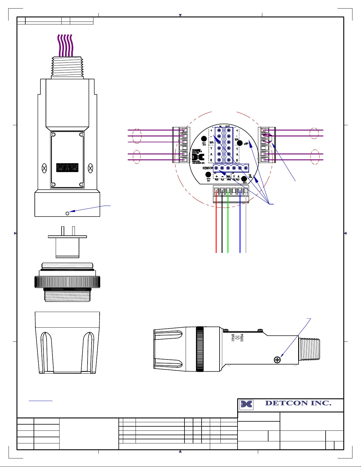
4
Sensor Wiring
to Junction Box
Intelligent
Transmitter
Module
(ITM)
Customer
Supplied Wiring (In)
Transient Protection Module
(TPM) P/N 500-003087-100
Explosion
Proof
Junction Box
Customer
Supplied Wiring
(Out to next Device)
Power to next Device
(+)
(-)
mA
PGM1
ZERO
MODEL
PI-700
PGM2
SPAN
A(+)
B(-)
Modbus RS-485 to
Host Control Device
A(+)
B(-)
Modbus RS-485 to
next Device
VOC
Housing Bottom
Locking Set-Screw
Install a 100-250 Ohm
resistor if the 4-20mA
output is not used
Ground Points
Earth-Ground connection
is made via 6-32
mounting holes.
Intelligent
Plug-in
Sensor
Splash Guard
P/N 613-120000-700
Remove Splash Guard
Adapter from ITM to
access Plug-in Sensor
Splash Guard Adapter
P/N 602-003295-FLT
Wiring to
Sensor Assembly
6-32 threaded
Ground point
NOTES:
det c on , i nc .
3200 Research Forest Dr. A-1 * The W oodlands Texas 77381 * www.detcon.com
detcon inc.
Power from and 4-20mA
out to Control Device
(+)
(-)
mA
CLIENT:
PROJECT:
Rev DATE DESCRIPTION
DRN CHKD
REF. DWGS
P.O. NO.
REQ. NO.
PROJECT NO.
SERIAL NO.
PLANT:
NA
NA
NA
NA
NA
The information and technical data disclosed by
this document may be used and disseminated
only for the purposes and to the extent
specifically authorized by Detcon Incorporated
in writing. Such information and technical data
are proprietary to Detcon Incorporated and may
not be used or disseminated except as provided
in the foregoing sentence.
4
3
2
1
0
11/20/13
06/25/10
01/14/08
04/01/07
08/01/06
Changes to Housing and Splashguard
Add draw ing for Aluminum Condulet
Removed yellow wire
TPM Changed
RELEASE FOR MAN UFACTURE
REVISION HISTORY
RH
RH
RH
RH
RH
LU
SF
SF
EM
SF
BM
BM
BM
BM
BM
APPD
3228
3228
3228
3228
3228
DWG #
Updates
Updates
Updates
Updates
Updates
SUBJECT
NA
DRAWN BY:
R HUTSKO
FIRST ISSUE:
08/01/06
PI-700 Series
Breakaway and Wiring
NA
_
SCALE
NTS
SALES ORDER NO.
NA
DRAWING NO.
3228-1
SHEET NUM.
SIZE REV
NA
A
4
REV
3207-1
A
DRAWING NO.
JOB NO.NASIZE
Red
(+)mA(-)
Blk
Blu
Grn
A(+)
Wht
B(-)
Page 60

Model DM-700
This page left intentionally blank
Shipping Address: 4055 Technology Forest Blvd., The Woodlands Texas 77381
Mailing Address: P.O. Box 8067, The Woodlands Texas 77387-8067
Phone: 888.367.4286, 281.367.4100 • Fax: 281.292.2860 • www.detcon.com • [email protected]
PI-700 Instruction Manual Rev. 2.5
Page 61
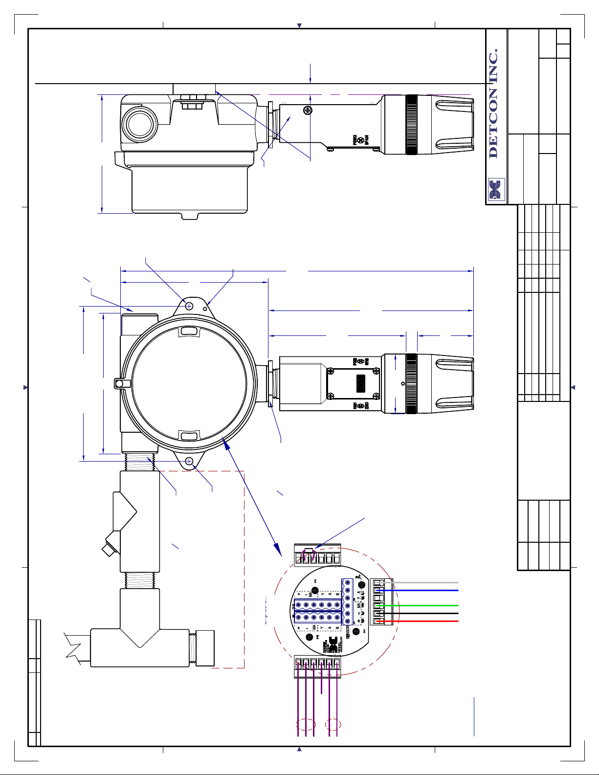
4
REV
A
3228-2
SIZE
DRAWING NO.
mounting surface)
Wall (or other
Spacer
and Mounting
Bolt
Mounting
4.25"
ITM
PI-700 Series
Wiring, Dimensional,
NANTS
NA
SALES ORDER NO.
SHEET NUM.
SCALE
_
NA
3200 Res earch Forest Dr. A-1 * The W oodlands Texas 77381 * www.detcon.com
08/01/06
NA
detcon, inc.
CLIENT:
Ground Point
6-32 threaded
Use Spacers to move
the J-Box and Sensor
allow access to Sensor
wall at least 0.25-0.5" to
Ø0.265"
" NPT Fitting
Mounting Hole
4
3
Plug unused ports
5.25"
8-32 Threaded
Ground Point
Assembly away from the
Typ.
12.55"
7.3"
Typ.
R. Hutsko
PROJECT:
Updates
Updates
3228
3228
BMSFRH
BMLURH
FIRST ISSUE:
DRAWN BY:
Updates
Updates
SUBJECT
REF. DWGS
3228BMEMRH UpdatesTPM Changed04/01/071
3228
3228
DWG #
BMSFRH
BMSFRH
APPDDRN CHKD
4.9"
Typ.
5"
5.5"
Mounting Holes
Junction-Box
(Detcon's J-Box Shown)
Explosion Proof Housing
MODEL
PI-700
detcon inc.
VOC
2.125"
(ITM)
2"
Removed yellow wire01/14/082
RELEASE FOR MANUFACTURE08/01/060
Changes to Housing and Splashguard11/20/134
Add drawing for Aluminum Condulet06/25/103
REVISION HISTORY
Rev DATE DESCRIPTION
Splash Guard
Housing Bottom
Transmitter Module
" NPT Fitting
4
3
Ø0.265"
Mounting Hole
EYS Seal Fitting
" NPT Fitting
4
3
Installation Method
Recommended Electrical
NA
JOB NO.
"T"
Proof
Junction Box
Model-700 Inteligent
this document may be used and disseminated
The information and technical data disclosedby
NA
output is not used
resistor if the 4-20mA
Install a 100-250 Ohm
P.O. NO.
Wht
Blu
Grn
Blk
Red
B(-)
A(+)
mA
Wiring to
(-)
(+)
Sensor Assembly
not be used or disseminated except as provided
only for the purposes and to the extent
in writing. Such information and technical data
are proprietary to Detcon Incorporated and may
in the foregoing sentence.
specifically authorized by Detcon Incorporated
NANANA
NA
PROJECT NO.
SERIAL NO.
REQ. NO.
PLANT:
SIZE
A
3228-2
4
Conduit
DRAWING NO.
REV
Drain
(-)
(+)
mA
B(-)
N/U
A(+)
Customer
Supplied Wiring
(TPM) P/N 500-003087-100
Transient Protection Module
Enclosure to ground unit
properly. Mount to bottom of
enclosure using 6-32 screws.
Mount TPM in Explosion Proof
NOTES:
If the Sensor is not mechanically
grounded to the Junction Box, and
insure proper grounding.
external ground strap should be used to
Page 62

Model DM-700
This page left intentionally blank
Shipping Address: 4055 Technology Forest Blvd., The Woodlands Texas 77381
Mailing Address: P.O. Box 8067, The Woodlands Texas 77387-8067
Phone: 888.367.4286, 281.367.4100 • Fax: 281.292.2860 • www.detcon.com • [email protected]
PI-700 Instruction Manual Rev. 2.5
Page 63
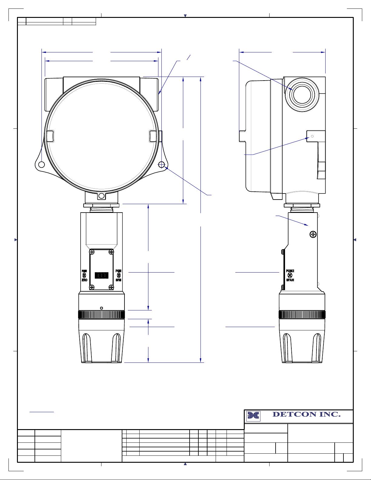
4
5.5" 3.95"
5.2"
Detcon's Aluminum
Explosion Proof
Junction-Box
(Condulet)
4
" NPT Port
Plug unused ports
5.825"
8-32 Threaded
Ground Point
Ø0.275"
Mounting
Hole
13.1" Typ
6-32 Threaded
Ground Point
detcon inc.
MODEL
4.88"
PI-700
Sensor Assembly
VOC
0.4" Typ
Splash Gaurd
2"
NOTES:
det c on , i nc .
3200 Research Forest Dr. A-1 * The W oodlands Texas 77381 * www.detcon.com
3
CLIENT:
PROJECT:
Rev DATE DESCRIPTION
DRN CHKD
REF. DWGS
P.O. NO.
REQ. NO.
PROJECT NO.
SERIAL NO.
PLANT:
NA
NA
NA
NA
NA
The information and technical data disclosed by
this document may be used and disseminated
only for the purposes and to the extent
specifically authorized by Detcon Incorporated
in writing. Such information and technical data
are proprietary to Detcon Incorporated and may
not be used or disseminated except as provided
in the foregoing sentence.
4
3
2
1
0
11/20/13
06/25/10
01/14/08
04/01/07
08/01/06
Changes to Housing and Splashguard
Add draw ing for Aluminum Condulet
Removed yellow wire
TPM Changed
RELEASE FOR MAN UFACTURE
REVISION HISTORY
RH
RH
RH
RH
RH
LU
SF
SF
EM
SF
BM
BM
BM
BM
BM
APPD
3228
3228
3228
3228
3228
DWG #
Updates
Updates
Updates
Updates
Updates
SUBJECT
NA
DRAWN BY:
R HUTSKO
FIRST ISSUE:
06/25/10
DM-700 Series
with Detcon Aluminum
NA
_
SCALE
NTS
Junction-Box
SALES ORDER NO.
NA
DRAWING NO.
3207-3
SHEET NUM.
SIZE REV
NAA4
REV
3207-3
A
DRAWING NO.
JOB NO.NASIZE
Page 64

Model DM-700
This page left intentionally blank
Shipping Address: 4055 Technology Forest Blvd., The Woodlands Texas 77381
Mailing Address: P.O. Box 8067, The Woodlands Texas 77387-8067
Phone: 888.367.4286, 281.367.4100 • Fax: 281.292.2860 • www.detcon.com • [email protected]
PI-700 Instruction Manual Rev. 2.5
 Loading...