


INSTRUCTION MANUAL
Detcon Model IR-700
IR-700 Combustible Gas Sensor
0-100% LEL and 0-50% LEL range
IR-700 CO2 Carbon Dioxide Gas Sensor
All Ranges
 DETCON, Inc.
4055 Technology Forest Blvd.,
The Woodlands, Texas 77381
Ph.281.367.4100 / Fax 281.298.2868
www.detcon.com
February 28, 2014 • Document #3169 • Revision 3.1

Model IR-700
This page left intentionally blank
Model IR-700 |
ii |

|
|
|
Model IR-700 |
|
|
|
Table of Contents |
|
|
1. |
Introduction .................................................................................................................................................. |
1 |
||
|
1.1 |
Description.......................................................................................................................................... |
1 |
|
|
1.1.1 Non-Dispersive Infrared (NDIR) Optical Sensor Technology ....................................................... |
1 |
||
|
1.1.2 |
Principle of Operation .................................................................................................................... |
2 |
|
|
1.1.3 |
Performance Characteristics ........................................................................................................... |
2 |
|
|
1.2 |
Sensor Electronics Design .................................................................................................................. |
3 |
|
|
1.2.1 |
Intelligent Transmitter Module....................................................................................................... |
3 |
|
|
1.3 |
Modular Mechanical Design............................................................................................................... |
3 |
|
|
1.4 |
Plug-in Replaceable Sensor ................................................................................................................ |
4 |
|
2. |
Installation .................................................................................................................................................... |
5 |
||
|
2.1 |
ATEX Operational Guidelines for Safe Use....................................................................................... |
5 |
|
|
2.2 |
Sensor Placement ................................................................................................................................ |
6 |
|
|
2.3 |
Sensor Contaminants and Interference ............................................................................................... |
7 |
|
|
2.4 |
Mounting Installation.......................................................................................................................... |
7 |
|
|
2.5 |
Electrical Installation .......................................................................................................................... |
8 |
|
|
2.6 |
Field Wiring ........................................................................................................................................ |
9 |
|
|
2.7 |
Initial Start Up................................................................................................................................... |
11 |
|
3. |
Operation .................................................................................................................................................... |
12 |
||
|
3.1 |
Programming Magnet Operating Instructions................................................................................... |
12 |
|
|
3.2 |
Operator Interface ............................................................................................................................. |
13 |
|
|
3.3 |
Normal Operation ............................................................................................................................. |
14 |
|
|
3.4 |
Calibration Mode (AutoZero and AutoSpan) ................................................................................... |
15 |
|
|
3.4.1 |
AutoZero....................................................................................................................................... |
15 |
|
|
3.4.2 |
AutoSpan ...................................................................................................................................... |
15 |
|
|
3.5 |
Program Mode .................................................................................................................................. |
17 |
|
|
3.5.1 |
View Sensor Status....................................................................................................................... |
18 |
|
|
3.5.2 |
Set AutoSpan Level ...................................................................................................................... |
19 |
|
|
3.5.3 Set Gas Type& Range .................................................................................................................. |
20 |
||
|
3.5.4 |
Set Gas Factor............................................................................................................................... |
20 |
|
|
3.5.5 |
Set Serial ID ................................................................................................................................. |
21 |
|
|
3.5.6 |
Set Sensor Gain ............................................................................................................................ |
22 |
|
|
3.5.7 |
Signal Output Check..................................................................................................................... |
22 |
|
|
3.5.8 |
Restore Factory Defaults .............................................................................................................. |
23 |
|
|
3.6 |
Program Features .............................................................................................................................. |
23 |
|
|
3.6.1 |
Operational Features..................................................................................................................... |
24 |
|
|
3.6.2 |
Fault Diagnostic/Fail-Safe Features ............................................................................................. |
24 |
|
4. |
RS-485 Modbus™ Protocol ....................................................................................................................... |
27 |
||
Content Description............................................................................................................................................. |
27 |
|||
5. |
Service and Maintenance............................................................................................................................ |
29 |
||
|
5.1 |
Calibration Frequency....................................................................................................................... |
29 |
|
|
5.2 |
Visual Inspection .............................................................................................................................. |
29 |
|
|
5.3 |
Condensation Prevention Packet....................................................................................................... |
29 |
|
|
5.4 |
Replacement of IR Plug-in Combustible Gas Sensor ....................................................................... |
29 |
|
|
5.5 |
Replacement of ITM ......................................................................................................................... |
30 |
|
|
5.6 |
Replacement of IR-700 Sensor Assembly ........................................................................................ |
30 |
|
6. |
Troubleshooting Guide ............................................................................................................................... |
31 |
||
7. Customer Support and Service Policy ........................................................................................................ |
34 |
|||
8. |
IR-700 Sensor Warranty............................................................................................................................. |
35 |
||
9. |
Appendix .................................................................................................................................................... |
36 |
||
|
9.1 |
Specifications.................................................................................................................................... |
36 |
|
Model IR-700 |
|
iii |
||

|
|
Model IR-700 |
9.2 |
Spare Parts, Sensor Accessories, Calibration Equipment ................................................................. |
38 |
9.3 |
Model IR-700 Engineering Drawings............................................................................................... |
39 |
10. |
Revision Log ......................................................................................................................................... |
39 |
|
Table of Figures |
|
Figure 1 Sensor Cell Construction ....................................................................................................................... |
1 |
|
Figure 2 Principle of Operation............................................................................................................................ |
2 |
|
Figure 3 Response Curve ..................................................................................................................................... |
2 |
|
Figure 4 ITM Circuit Functional Block Diagram................................................................................................. |
3 |
|
Figure 5 Sensor Assembly Front View ................................................................................................................ |
3 |
|
Figure 6 Sensor Assembly Breakaway................................................................................................................. |
4 |
|
Figure 7 IR Sensor Cell ........................................................................................................................................ |
4 |
|
Figure 8 ATEX Approval Label........................................................................................................................... |
5 |
|
Figure 9 Outline and Mounting Dimensions ........................................................................................................ |
8 |
|
Figure 10 Typical Installation .............................................................................................................................. |
9 |
|
Figure 11 Sensor Wire Connections................................................................................................................... |
10 |
|
Figure 12 Magnetic Programming Tool ............................................................................................................. |
12 |
|
Figure 13 Magnetic Programming Switches ...................................................................................................... |
12 |
|
Figure 14 IR-700 Software Flowchart................................................................................................................ |
14 |
|
Figure 15 Sensor Assembly................................................................................................................................ |
29 |
|
|
List of Tables |
|
Table 1Wire Gauge vs. Distance .......................................................................................................................... |
9 |
|
Table 2 Gas Factors............................................................................................................................................ |
21 |
|
Table 3 Modbus™ Registers .............................................................................................................................. |
27 |
|
Table 4 Modbus™ Special Registers ................................................................................................................. |
28 |
|
|
Shipping Address: 4055 Technology Forest Blvd., The Woodlands Texas 77381 |
|
Mailing Address: P.O. Box 8067, The Woodlands Texas 77387-8067 |
|
Phone: 888.367.4286, 281.367.4100 • Fax: 281.292.2860 • www.detcon.com • sales@detcon.com |
Model IR-700 |
iv |
Model IR-700
1.Introduction
1.1Description
Detcon Model IR-700 combustible gas sensors are non-intrusive “Smart” sensors designed to detect and monitor combustible hydrocarbon gases in air. The range of detection is 0-100% LEL or 0-50% LEL. The Model IR-700 CO2 Sensor is designed to detect CO2 in air at ranges from 0-.3% to 0-100% by Volume. The sensor features an LED display of current reading, fault and calibration status. The unit is equipped with standard analog 4-20mA and Modbus™ RS-485 outputs. A primary feature of the sensor is its method of automatic calibration, which guides the user through each step via fully scripted instructions shown on the LED display.
The microprocessor-supervised electronics are packaged in an encapsulated module and housed in an explosion proof casting. The unit includes a 4 character alpha/numeric LED used to display sensor readings and the sensor’s menu-driven interface when the hand-held programming magnet is used.
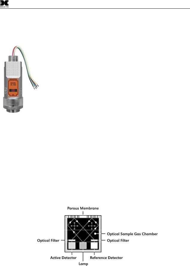
1.1.1Non-Dispersive Infrared (NDIR) Optical Sensor Technology
The sensor technology is designed as a miniature plug-in replaceable component, which can easily be changed out in the field. The NDIR sensor consists of an infrared lamp source, two pyro electric detectors, and an optical gas sample chamber. The lamp source produces infrared radiation, which interacts with the target gas as it is reflected through the optical gas sample chamber. The infrared radiation contacts each of the two pyro electric detectors at the completion of the optical path. The “active” pyro electric detector is covered by a filter specific to the part of the IR spectrum where the target gas absorbs light. The “reference” pyro electric detector is covered by a filter specific to the non-absorbing part of the IR spectrum. When the target gas is present, it absorbs IR radiation and the signal output from the active detective decreases accordingly. The reference detector output remains unchanged. The ratio of the active and reference detector outputs are then used to compute the target gas concentration.
The technique is referred to as non-selective and may be used to monitor most any combustible hydrocarbon gas. The technique for CO2 is similar except that the sensor provides a selective response to CO2. Unlike catalytic bead type sensors, Detcon IR sensors are completely resistant to poisoning from corrosive gases and they can operate in the absence of an oxygen background. The sensors are characteristically stable and capable of providing reliable performance for periods exceeding 5 years in most industrial environments.
Figure 1 Sensor Cell Construction
IR-700 Instruction Manual |
Rev. 3.1 |
Page 1 of 40 |
Model IR-700
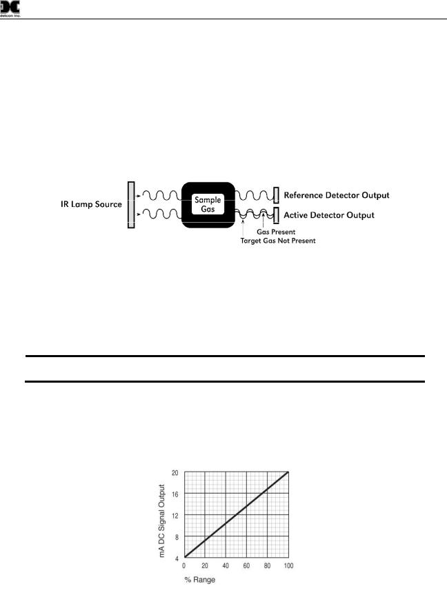
1.1.2Principle of Operation
The target gas diffuses through a sintered stainless steel flame arrestor and into the volume of the sample gas optical chamber. An alternating miniature lamp provides a cyclical IR radiation source, which reflects through the optical gas sample chamber and terminates at two pyro electric detectors. The active and reference pyro electric detectors each give an output which measures the intensity of the radiation contacting their surface. The active detector is covered by an optical filter specific to the part of the IR spectrum where the target gas absorbs light. The reference detector is covered by a filter specific to the non-absorbing part of the IR spectrum. When present, the target gas absorbs a fraction of the IR radiation and the signal output from the active detector decreases accordingly. The signal output of the reference detector remains unchanged in the presence of the target gas. The ratio of the active/reference signal outputs is then used to compute the target gas concentration. By using the ratio of the active/reference signal outputs, measurement drift caused by the changes in the intensity of the IR lamp source or changes in the optical path’s reflectivity is prevented.
Figure 2 Principle of Operation
1.1.3Performance Characteristics
The IR sensor maintains strong sensitivity to most all combustible hydrocarbon gases in the Lower Explosive Limit (LEL) range, as shown in the response curve illustration below. When compared with the typical catalytic bead LEL sensor, the IR sensor exhibits improved long-term zero and span stability. Typical zero calibration intervals would be quarterly to semi-annual and typical span intervals would be semi-annual to annual. However, actual field experience is always the best determination of appropriate calibration intervals.
NOTE: The IR-700 sensor will not respond to combustible gases that are not hydrocarbons, such as H2, NH3, CO, H2S….etc. It can only be used to measure hydrocarbon type gases.
The IR sensor generates different signal sensitivity levels for different combustible hydrocarbon target gases. Unless otherwise specified the IR-700 sensor will be factory calibrated for methane service. If the target hydrocarbon gas is other than methane, then the unit will have to be span calibrated and configured accordingly per this Instruction Manual.
Figure 3 Response Curve
IR-700 Instruction Manual |
Rev. 3.1 |
Page 2 of 40 |

Model IR-700
1.2 Sensor Electronics Design
1.2.1Intelligent Transmitter Module
The Intelligent Transmitter Module (ITM) is a fully encapsulated microprocessor-based package that accepts a plug-in field replaceable combustible gas sensor and for IR-700 CO2 sensors, a plug-in replaceable CO2 sensor. Circuit functions include extensive I/O circuit protection, sensor pre-amplifier, on-board power supplies, microprocessor, LED display, magnetic programming switches, a linear 4-20mA DC output, and a Modbus™ RS-485 output. Magnetic program switches located on either side of the LED Display are activated via a hand-held magnetic programming tool, thus allowing non-intrusive operator interface with the ITM. Calibration can be accomplished without declassifying the area. Electrical classifications are Class I, Division 1, Groups B C D and Class I, Zone 1, Group IIB+H2.
|
|
|
|
|
|
Display |
|
|
|
|
|
|
|
|
|
|
|
|
Pre-Amp |
|
Micro- |
|
|
|
|
Analog 4-20mA Out |
|
|
|
|
|||||
Plug-In |
|
|
Processor |
|
|
RS-485 |
|
I/O |
Sensor |
|
|
|
|
|
|
Circuit |
|
|
|
|
|
|
|
|||
Element |
|
|
|
|
|
|
|
Protection |
|
|
|
|
|
|
|||
|
|
|
|
|
|
4-20mA |
|
Modbus™ RS-485 Output |
|
|
|
|
|
|
|
|
|
|
|
|
|
|
|
|
|
|
Power In
Power Supply
Figure 4 ITM Circuit Functional Block Diagram
Program Switch #1
Splash Guard Adapter
Locking Set-Screw
detcon inc. |
MODEL |
IR-700 |
LEL Sensor |
LED Display
Program Switch #2
Figure 5 Sensor Assembly Front View
1.3 Modular Mechanical Design
The Model IR-700 Sensor Assembly is completely modular and made up of four parts (See Error! Reference source not found. for Assembly Breakaway):
1)IR-700 Intelligent Transmitter Module (ITM)
2)Field Replaceable Plug-in Infra-Red Gas Sensor
IR-700 Instruction Manual |
Rev. 3.1 |
Page 3 of 40 |
Model IR-700
3)Model 700 Housing Bottom Assembly (contains the Housing Bottom, Flame Arrestor, Retaining Ring, and rubber O-Rings)
4)Splash Guard.
NOTE: All metal components are constructed from electro-polished 316 Stainless Steel in order to maximize corrosion resistance in harsh environments.
|
Plug-in Replacable |
|
|
Housing Bottom |
Combustible |
Lens and LCD |
|
Hydrocarbon Sensor |
Display |
||
Assembly |
|||
|
|
Splash Guard
O-Rings
ensorS LEL |
MODEL 700-IR |
.inc detcon |
|
|
|
Magnetic |
Intelligent Transmitter Module (ITM) |
|
|
|
||
Housing Bottom |
Micro-Processor controlled circuit |
|||
Locking Set-Screw |
Programming |
encapsulated in an explosion proof |
||
|
|
|
Switches |
housing. |
Figure 6 Sensor Assembly Breakaway
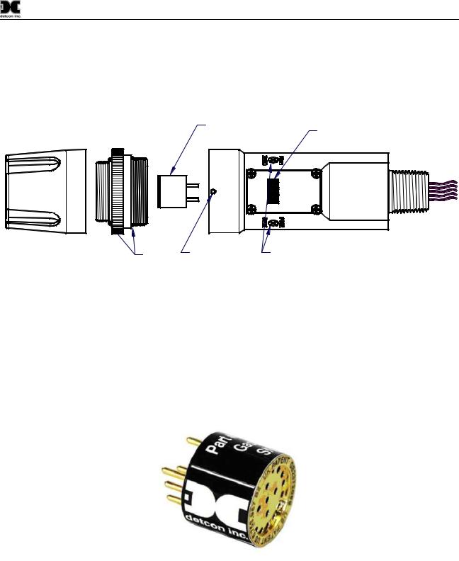
1.4 Plug-in Replaceable Sensor
The Detcon IR combustible hydrocarbon gas sensor is a unique and miniaturized single-package optical design that generates enough internal heat to prevent condensation. It is packaged as a true plug-in replaceable type sensor with over-sized gold-plated connections that eliminate corrosion problems. It can be accessed and replaced in the field very easily by releasing the locking screw and unthreading the housing bottom. The Detcon IR combustible hydrocarbon gas sensor and the CO2 gas sensor have an infinite shelf life, and are supported by a 5-year pro-rated warranty. The expected service life is 5 years or greater.
Figure 7 IR Sensor Cell
IR-700 Instruction Manual |
Rev. 3.1 |
Page 4 of 40 |
Model IR-700
2.Installation
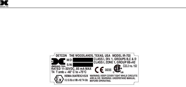
2.1ATEX Operational Guidelines for Safe Use
1.Install sensor only in areas with classifications matching with those described on the ATEX approval label. Follow all warnings listed on the label.
Figure 8 ATEX Approval Label
2.Ensure that the sensor is properly threaded into a suitable explosion-proof rated junction box with a downward pointing female ¾” NPT threaded connection. The sensor should be threaded up at least 5 full turns until tight, with the LED display facing forward. Avoid use of Teflon Tape, or any type of non-conductive pipe thread coating on the NPT threaded connection.
3.A good ground connection should be verified between the sensor’s metal enclosure and the junction box. If a good ground connection is not made, the sensor can be grounded to the junction box using the sensor’s external ground lug. Also verify a good ground connection between the junction box and earth ground. Installer shall use ring terminal to make connection to earth ground to be secured by screw and lock washer on sensor housing.
4.Ensure that the Housing Bottom and plug-in sensor are installed during operation. The Housing Bottom should be threaded tightly to the Intelligent Transmitter Module. The locking setscrew (M3.5 x 0.6 6g6h Stainless Steel Allen set screw cup point with yield strength of greater than 40,000 PSI, typical 80,000 PSI) should then be tightened down to keep the Housing Bottom from being inadvertently removed or from becoming loose under vibration. The locking setscrew ensures that Housing Bottom is only removable by authorized personnel with the use of special tools. A M1.5 Allen Wrench is required. If screw requires replacement, only an identical screw may be used.
5.Removal of the Housing Bottom violates the Ex d protection method and hence power must be removed from the sensor prior its safe removal.
6.The screws holding down the retaining plate label are special fasteners of type Stainless Steel, Phillips Pan-head Machine screw, M3 x 0.5 6g6h having yield strength of greater than 40,000 PSI, typical 80,000 PSI. If screw requires replacement, only an identical screw may be used.
7.Proper precautions should be taken during installation and maintenance to avoid the build-up of static charge on the plastic components of the sensor. These include the splashguard and splashguard adapter.
8.Do not operate the sensor outside of the stated operating temperature limits.
9.Do not operate the sensor outside the stated operating limits for voltage supply.
10.These sensors meet EN60079-0:2009, EN60079-1:2007.
IR-700 Instruction Manual |
Rev. 3.1 |
Page 5 of 40 |

Model IR-700
2.2 Sensor Placement
Selection of sensor location is critical to the overall safe performance of the product. Five factors play an important role in selection of sensor locations:
(1)Density of the gas to be detected
(2)Most probable leak sources within the industrial process
(3)Ventilation or prevailing wind conditions
(4)Personnel exposure.
(5)Maintenance access.
Density
Placement of sensors relative to the density of the target gas is such that sensors for the detection of heavier than air gases should be located within 4 feet of grade as these heavy gases will tend to settle in low lying areas. For gases lighter than air, sensor placement should be 4-8 feet above grade in open areas or in pitched areas of enclosed spaces.
NOTE: Methane is lighter than air. Most other combustible hydrocarbon gases are heavier than air. Compare the molecular weight, density, or specific gravity of the target gas(es) with that of air to determine appropriate placement.
Leak Sources
The most probable leak sources within an industrial process include flanges, valves, and tubing connections of the sealed type where seals may either fail or wear. Other leak sources are best determined by facility engineers with experience in similar processes.
Ventilation
Normal ventilation or prevailing wind conditions can dictate efficient location of gas sensors in a manner where the migration of gas clouds is quickly detected.
Personnel Exposure
The undetected migration of gas clouds should not be allowed to approach concentrated personnel areas such as control rooms, maintenance or warehouse buildings. A more general and applicable thought toward selecting sensor location is combining leak source and perimeter protection in the best possible configuration.
Maintenance Access
Consideration should be given to providing easy access for maintenance personnel. Consideration should also be given to the consequences of close proximity to contaminants that may foul the sensor prematurely.
NOTE: In all installations the gas sensor should point straight down. Refer to Figure 10. Improper sensor orientation may result in false readings and permanent sensor damage.
Additional Placement Considerations
The sensor should not be positioned where it may be sprayed or coated with surface contaminating substances. Painting sensor assemblies is prohibited.
IR-700 Instruction Manual |
Rev. 3.1 |
Page 6 of 40 |
Model IR-700
Although the sensor is designed to be RFI resistant, it should not be mounted in close proximity to highpowered radio transmitters or similar RFI generating equipment.
When possible, mount the sensor in an area void of high wind, accumulating dust, rain, or splashing from hose spray, direct steam releases, and continuous vibration. If the sensor cannot be mounted away from these conditions then make sure the Detcon Harsh Environment Splashguard accessory is used.
Do not mount in locations where temperatures will exceed the operating temperature limits of the sensor. Where direct sunlight leads to exceeding the high temperature-operating limit, use a sunshade to help reduce temperature.
2.3 Sensor Contaminants and Interference
Detcon IR-700 combustible hydrocarbon gas sensors may be adversely affected by exposure to certain airborne substances. Loss of sensitivity or corrosion may be gradual if such materials are present in sufficient concentrations.
The performance of the IR sensor may be impaired during operation in the presence of substances that can cause corrosion on gold plating. Other inhibiting substances are those that can coat the internal walls of the optical chamber and reduce reflectivity. These include but are not limited to heavy oil deposits, dust/powder, water condensation, and salt formation. Continuous and high concentrations of corrosive gases (such as Cl2, H2S, HCl …etc.) may also have a detrimental long-term effect on the sensor’s service life.
The presence of such substances in an area does not preclude the use of this sensor technology, although it is likely that the sensor lifetime will be shorter as a result. Use of this sensor in these environments may require more frequent calibration checks to ensure safe system performance.
For the IR-700 Combustible gas sensors there are no known cross-interference gases that are not combustible hydrocarbon gases. For the IR-700 CO2 Sensor, there are no known cross interference gases.
2.4 Mounting Installation
The IR-700 sensor assembly is designed to be threaded into a ¾” female NPT fitting of a standard cast metal Explosion-Proof Enclosure or Junction Box. There are two wrench flats on the upper section of the sensor that should be used to thread the sensor into the ¾” female NPT receiving connection. Thread the sensor up until tight (5 turns is typically expected) and until the display is facing the direction that the sensor will normally be viewed and accessed.
The IR-700 should be vertically oriented so that the sensor points straight downward. The explosion-proof enclosure or junction box would then typically be mounted on a wall or pole. Detcon provides a standard selection of junction boxes available as sensor accessories (See Figure 4 below), but any appropriately rated enclosure with a downward facing ¾” NPT female connection will suffice.
When mounting on a wall, it is recommended to use a 0.25”-0.5” spacer underneath the mounting ears of the Detcon standard J-Box to offset the sensor assembly from the wall and create open access around the sensor assembly. Spacing requirements for other junction boxes may vary.
When mounting on a pole, secure the Junction Box to a suitable mounting plate and attach the mounting plate to the pole using U-Bolts. (Pole-Mounting brackets for Detcon J-Box accessories are available separately.)
IR-700 Instruction Manual |
Rev. 3.1 |
Page 7 of 40 |

|
|
|
|
|
|
Model IR-700 |
||
Conduit |
|
|
|
|
|
|
|
|
|
|
|
Mounting Holes |
|
3 4" NPT Fitting |
|
|
|
|
|
|
5.5" |
|
|
|
||
|
|
|
5" |
|
Plug unused ports |
|
|
|
|
|
|
|
|
|
|
|
|
"T" |
EYS Seal Fitting |
|
|
|
|
Ø0.265" |
|
|
|
|
|
|
|
Mounting Hole |
|
|
|
|
3 4" NPT Fitting |
Explosion Proof Housing |
|
Mounting Bolt |
Spacer |
|
||
|
|
|
|
|||||
|
|
|
|
|
|
|||
|
|
|
Junction-Box |
|
5.25" |
|
|
|
|
|
(Detcon's J-Box Shown) |
|
|
|
|||
|
|
|
|
|
|
|||
Drain |
Ø0.265" |
|
|
|
|
|
|
surface)mounting |
Mounting Hole |
|
|
12.5" |
Ground Point |
Wallother(or |
|||
|
|
|
|
|
8-32 Threaded |
|
|
|
|
Recommended Electrical |
|
|
|
Ground Point |
|
|
|
|
Installation Method |
|
|
|
|
6-32 threaded |
|
|
|
|
|
|
|
|
|
|
|
|
3 4" NPT Fitting |
|
|
Typ. |
|
|
|
|
|
|
|
|
Use Spacers to move |
|
|
||
|
|
|
|
|
|
|
|
|
|
|
|
|
|
|
the J-Box and Sensor |
|
|
|
|
|
|
|
Assembly away from the |
|
|
|
|
|
|
|
4.9" |
wall at least 0.25-0.5" to |
|
|
|
|
|
IR-700 Inteligent |
detcon inc. |
|
allow access to Sensor |
|
|
|
|
|
MODEL |
Typ. |
|
|
|
|
|
|
|
Transmitter Module |
IR-700 |
|
|
|
|
|
|
|
|
|
|
ITM |
|
|
|
|
|
(ITM) |
|
|
7.2" |
|
|
|
|
|
|
|
|
|
|
|
|
|
|
|
LEL |
|
Typ. |
|
|
|
|
|
Housing Bottom |
2.125" |
|
|
|
|
|
|
|
|
|
|
|
|
|
|
Splash Guard 
2"
Figure 9 Outline and Mounting Dimensions
2.5 Electrical Installation
The Sensor Assembly should be installed in accordance with local electrical codes. The sensor assemblies are CSA/NRTL approved (US and Canada) for Class I, Division 1, Groups B, C, & D area classifications, and are ATEX Approved for Class I, Zone 1, Group IIB+H2 area classifications.
Proper electrical installation of the gas sensor is critical for conformance to Electrical Codes and to avoid damage due to water leakage. Refer to Figure 10 and Figure 11 for proper electrical installation.
NOTE: If a conduit run exits the secondary port, repeat the installation technique shown in Figure 10.
In Figure 10, the drain allows H2O condensation inside the conduit run to safely drain away from the sensor assembly. The electrical seal fitting is required to meet the National Electrical Code per NEC Article 500-3d (or Canadian Electrical Code Handbook Part 1 Section 18-154). Requirements for locations of electrical seals are covered under NEC Article 501-5. Electrical seals also act as a secondary seal to prevent water from entering the wiring terminal enclosure. However, they are not designed to provide an absolute water-tight seal, especially when used in the vertical orientation.
NOTE: A conduit seal is typically required to be located within 18" of the J-Box and Sensor Assembly. Crouse Hinds type EYS2, EYD2 or equivalent are suitable for this purpose.
IR-700 Instruction Manual |
Rev. 3.1 |
Page 8 of 40 |

Model IR-700
NOTE: The Detcon Warranty does not cover water damage resulting from water leaking into the enclosure. However, since the electronics are 100% epoxy encapsulated, only the wire terminations could get wet. Moisture could cause abnormal operation and possibly corrosion to the terminal connections, but permanent damage to the sensor would not be expected.
Conduit
|
Plug any unused |
|
ports |
"T" |
EYS Seal Fitting |
|
Explosion Proof |
|
Housing |
Drain |
(J-Box) |
|
Explosion |
|
Customer |
Proof |
|
Junction Box |
||
Supplied Wiring |
||
|
||
(+) |
|
|
(-) |
|
|
mA |
|
|
N/U |
|
|
A(+) |
|
|
B(-) |
|
Transient Protection Module
(TPM) P/N 500-003087-100
Mount TPM in Explosion Proof Enclosure to ground unit properly. Mount to bottom of enclosure using 6-32 screws.
|
|
IR-700 |
|
|
Sensor |
|
|
Assembly |
|
|
6-Pin Pheonix Plug |
Red Blk Grn |
Blu Wht |
P/N 306-175705-100 |
|
||
(+) (-) mA |
A(+) B(-) |
|
Wiring to |
|
|
Sensor Assembly |
||
detcon inc. |
MODEL |
IR-700 |
LEL Sensor |
Figure 10 Typical Installation
NOTE: Any unused ports should be blocked with suitable ¾” male NPT plugs. Detcon Supplies one ¾” NPT male plug with their accessory J-box enclosures. If connections are other than ¾” NPT, use an appropriate male plug of like construction material.
2.6 Field Wiring
Detcon Model IR-700 combustible hydrocarbon gas sensor assemblies require three conductor connections between power supplies and host electronic controller’s 4-20mA output, and 2 conductor connections for the Modbus™ RS-485 serial interface. Wiring designations are + (DC), – (DC), mA (sensor signal), and Modbus™ RS-485 A (+), and B (-). Maximum wire length between sensor and 24VDC source is shown in the Table below. Maximum wire size for termination in the Detcon J-Box accessory is 14AWG.
Table 1Wire Gauge vs. Distance
|
|
AWG |
|
|
Wire Dia. |
|
|
Meters |
|
|
Feet |
|
|
Over-Current |
|
|
|
|
|
|
|
|
|
|
|
|
Protection |
|
|
||||
|
|
|
|
|
|
|
|
|
|
|
|
|
|
|
|
|
|
22 |
|
|
0.723mm |
700 |
|
2080 |
|
|
|
3A |
|
||||
|
20 |
|
|
0.812mm |
1120 |
|
3350 |
|
|
|
5A |
|
||||
IR-700 Instruction Manual |
|
|
|
|
Rev. 3.1 |
|
|
|
|
Page 9 of 40 |
||||||

Model IR-700
18 |
1.024mm |
1750 |
5250 |
7A |
16 |
1.291mm |
2800 |
8400 |
10A |
14 |
1.628mm |
4480 |
13,440 |
20A |
NOTE 1: Wiring table is based on stranded tinned copper wire and is designed to serve as a reference only.
NOTE 2: Shielded cable is required for installations where cable trays or conduit runs include high voltage lines or other possible sources of induced interference. Separate conduit runs are highly recommended in these cases.
NOTE 3: The supply of power should be from an isolated source with over-current protection as stipulated in table.
Terminal Connections
CAUTION: Do not apply System power to the sensor until all wiring is properly terminated. Refer to Section 2.7Initial Start Up
Customer |
|
|
|
Supplied Wiring (In) |
Explosion |
Customer |
|
Power from and 4-20mA |
Proof |
Supplied Wiring |
|
Junction Box |
(Out to next Device) |
||
out to Control Device |
|||
|
|
||
(+) |
|
(+) |
|
(-) |
|
(-) |
|
mA |
|
mA |
|
A(+) |
|
A(+) |
|
B(-) |
|
B(-) |
Modbus RS-485 to Host Control Device
Modbus RS-485 to next Device
Red |
Blk |
Grn |
Blu |
Wht |
(+) |
(-) |
mA |
A(+) |
B(-) |
Wiring to Sensor Assembly
Install a 100-250 Ohm resistor if the 4-20mA output is not used
Figure 11 Sensor Wire Connections
a)Remove the junction box cover. Identify the terminal blocks for customer wire connections.
b)Observing correct polarity, terminate the 3-conductor 4-20mA field wiring (+, -, mA) to the sensor assembly wiring in accordance with the detail shown in Figure 11. If the 4-20mA output is not used, the green wire from the sensor must be connected to the (-) terminal on the Transient Protection Module.
NOTE: If the 4-20mA output is not being used, the Green wire from the sensor m ustbe connected to the Black wire at the (-) terminal on the Transient Protection Module to ensure RS-485 communication is not disrupted by a 4-20mA Fault.
c)If applicable, terminate the RS-485 serial wiring as shown in Figure 11. Use the second plug (Out) as termination point on the customer side to facilitate a continuous RS-485 serial loop
IR-700 Instruction Manual |
Rev. 3.1 |
Page 10 of 40 |

Model IR-700
The RS-485 (if applicable) requires 24 gauge, two conductor, shielded, twisted pair cable between sensor and host controller. General Cable Commodore part number ZO16P0022189 is recommended.
NOTE: Install a 120 ohm resistor across A & B terminals on the last sensor in the serial loop.
d)Trim all exposed wire leads if they are not permanently landed in a terminal block.
e)Replace the junction box cover.
2.7 Initial Start Up
Upon completion of all mechanical mounting and termination of all field wiring, apply system power in the range of 11.5-30 VDC (24 VDC typical) and observe the following normal conditions:
a)IR-700 display reads “0”, and no fault messages are flashing.
b)A temporary non-zero reading may occur as the sensor reaches stabilization. The reading will converge to “0” within 1-2 minutes of power-up, assuming there is no combustible gas in the area of the sensor.
NOTE: The 4-20mA signal is held constant at 4mA for the first two minutes after power up.
Initial Operational Tests
After a warm up period of 1 hour, the sensor should be checked to verify sensitivity to combustible gas. For the IR-700 CO2 series sensors, test the sensor with a suitable CO2 span gas.
Material Requirements
Detcon PN 613-120000-700 700 Series Splash Guard with integral Cal Port –OR-
Detcon PN 943-000006-132 Threaded Calibration Adapter
Detcon PN 942-520124-050 Span Gas; 50% LEL methane/balance Air at fixed flow rate of 200 cc/min (for 0-100% range)
Detcon PN 942-520124-025 Span Gas; 25% LEL methane/balance Air at fixed flow rate of 200 cc/min (for 0-50% range)
a)Attach the calibration adapter to the threaded sensor housing. Apply the test gas at a controlled flow rate of 200cc/min. Allow 1-2 minutes for the reading to stabilize. Observe that during the 1-2 minutes the ITM display increases to a level near that of the applied calibration gas value.
b)Remove test gas and observe that the ITM display decreases to “0”.
Initial operational tests are complete. Detcon IR-700 combustible gas sensors are factory calibrated prior to shipment, and should not require significant adjustment on start up. However, it is recommended that a complete calibration test and adjustment be performed 16 to 24 hours after power-up. Refer to zero and span calibration instructions in Section 3.4.
IR-700 Instruction Manual |
Rev. 3.1 |
Page 11 of 40 |
 Loading...