


detcon inc.
Detcon MicroSafe™
DM-634 Oxygen Deficiency Sensor (0-25% O2)
Operator’s Installation & Instruction Manual
June 18,2009 • Document #2016T • Version 6.5

Table of Contents
3.0Description
3.1Principle of Operation
3.2Application
3.3Specifications
3.4Operating Software
3.5Installation
3.6Start-up
3.7Calibration
3.8Status of Programming: Alarms, Calibration Level, RS-485 ID, and Sensor Life
3.9Programming Alarms
3.10Program Features
3.11RS-485 Protocol
3.12Display Contrast Adjust
3.12A Trouble Shooting Guide
3.13Spare Parts List
3.14Warranty
3.15Service Policy
3.16Software Flow Chart
Detcon Model DM-634 Oxygen Sensor PG.2

3.0 DESCRIPTION
Detcon MicroSafe™ Model DM-634, oxygen deficiency sensors are non-intrusive “Smart” sensors designed to detect and monitor O2 in air over the range of 0-25%. One of the primary features of the sensor is its method of automatic calibration which guides the user through each step via instructions displayed on the backlit LCD. The sensor features field adjustable, fully programmable alarms and provides relays for two alarms plus fault as standard. The sensor comes with two different outputs: analog 4-20 mA, and serial RS-485. These outputs allow for greater flexibility in system integration and installation. The microprocessor supervised electronics are packaged as a plugin module that mates to a standard connector board. Both are housed in an explosion proof condulet that includes a glass lens window which allows for the display of sensor readings as well as access to the sensor’s menu driven features via a hand-held programming magnet.
3.0.1 Sensor Technology
The sensor technology is of the two electrode, galvanic metal air battery type cell, which is housed as a field replaceable plug–in module. The cell is diffusion limited and functions as a direct current generator proportional to the amount of oxygen adsorption. The sensors are temperature compensated and show good accuracy and stability over the operating temperature range -4° to +122° Fahrenheit. The sensor is warranted for two year and has an expected service life of up to two years in ambient air at 20.9% oxygen
Air Supply
 Diffusion Barrier
 Cathode
Load
Resistor
Anode
Construction of Galvanic Cell
Detcon Model DM-634 Oxygen Sensor PG.3
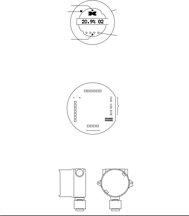
3.0.2 Microprocessor Control Circuit
The control circuit is microprocessor based and is packaged as a plug-in field replaceable module, facilitating easy replacement and minimum down time. Circuit functions include a basic sensor pre-amplifier, on-board power supplies, microprocessor, back lit alpha numeric display, alarm status LED indicators, magnetic programming switches, an RS-485 communication port, and a linear 4-20 mA DC output.
Program Switch #1
Display Contrast Adjust
Program Switch #2
PGM 1 |
Plug-in Microprocessor Control Circuit |
CONTRAST |
|
detcon inc.
MODEL HOUSTON, TEXAS DM-634
 Menu Driven Display
MicroSafe™ O2 Gas Sensor
ALM ALM
FLT 1 2 CAL
PGM 2
Alarm & Cal LEDs
3.0.3 Base Connector Board
The base connector board is mounted in the explosion proof enclosure and includes: the mating connector for the control circuit, reverse input and secondary transient suppression, input filter, alarm relays, lugless terminals for all field wiring, and a terminal strip for storing unused programming jumper tabs. The alarm relays are contact rated 5 amps @ 250 VAC, 5 amps @ 30 VDC and coil rated at 24 VDC. Gold plated program jumpers are used to select either the normally open or normally closed relay contacts.
|
|
|
|
|
|
|
|
|
|
|
|
|
|
|
Alarm Dry Contacts |
|||||||||||||
Optional Voltage |
|
|
|
|
|
|
|
|
|
|
|
|
|
|
FAULT |
|
ALM-2 |
|
ALM-1 |
|||||||||
|
|
|
|
|
|
|
|
|
|
|
|
|
|
|
|
|
|
|
|
|
|
|
|
|
|
|
|
|
|
|
|
|
|
|
|
|
|
|
|
|
|
|
NO/NC |
COM |
NO/NC |
COM |
NO/NC |
COM |
|||||||||
Use 250 ohm 1/4w |
|
|
|
|
|
|
|
|
|
|
|
|
|
|
||||||||||||||
Developing Resistor |
|
R1 |
|
|
|
|
|
|
|
|
|
|
|
|
|
|
|
|
|
|
|
|
|
|
||||
VDC Power In |
|
|
|
|
|
|
|
|
|
|
|
|
|
|
|
|
|
|
|
|
||||||||
|
|
|
|
|
|
|
|
|
|
|
|
|
|
|
|
|
|
|
|
|
|
|
|
|
|
|
|
|
|
|
|
|
|
|
|
|
|
|
|
|
|
|
|
|
|
|
|
|
|
|
|
|
|
|
|
|
|
|
|
|
|
|
|
|
|
|
|
|
|
|
|
|
|
|
|
|
|
|
|
|
|
|
|
|
|
|
|
|
|
|
|
|
|
|
|
|
|
|
|
|
|
|
|
|
|
|
|
|
|
|
|
|
|
|
|
4-20 mA Output |
|
|
|
|
|
|
|
|
|
|
|
|
|
|
|
|
|
|
|
|
|
|
|
|
|
|
|
|
|
|
|
|
|
|
|
|
MA |
|
|
|
|
|
|
|
|
|
|
|
|
|
|
|
|
||||
|
|
|
|
|
|
|
|
|
|
|
|
|
|
|
|
|
|
|
|
|
|
|
|
|
|
|
|
|
RS-485 In |
|
|
|
|
|
|
|
|
A |
|
|
|
|
|
|
|
|
|
|
|
|
|
|
|
|
|||
|
|
|
|
|
|
|
|
|
|
|
|
|
|
|
|
|
|
|
|
|
|
|
|
|
|
|
|
|
|
|
|
|
|
|
|
|
B |
|
|
|
|
|
|
|
|
|
|
|
|
|
|
|
|
||||
|
|
|
|
|
|
|
|
|
|
|
|
|
|
|
|
|
|
|
|
|
|
|
|
|
||||
|
|
|
|
|
|
|
|
|
|
|
|
|
|
|
|
|
|
|
|
|
|
|
|
|
|
|
|
|
RS-485 Out |
|
|
|
|
|
|
|
|
A |
|
|
|
|
|
|
|
|
|
|
|
|
|
|
|
|
|||
|
|
|
|
|
|
|
|
|
|
|
|
|
|
|
|
|
|
|
|
|
|
|
|
|
|
|
|
|
|
|
|
|
|
|
|
|
B |
|
|
|
|
|
|
|
|
|
|
|
|
|
|
|
|
||||
|
|
|
|
|
|
|
|
|
|
|
|
|
|
|
|
|
WHT |
BLK |
YEL |
BLU |
|
|
||||||
|
|
|
|
|
|
|
|
|
|
|
|
|
|
|
|
|
|
|
|
|
|
|
|
|
|
|
|
|
|
|
|
|
|
|
|
|
|
|
|
|
|
|
|
|
|
|
|
|
|
|
|
|
|
|
|
|
|
|
|
|
|
|
|
|
|
|
|
|
|
|
|
|
|
|
|
|
|
|
|
|
|
|
|
|
|
|
 NC ALARM 1
 NO
NO
 NC ALARM 2
 NO
NO
 NC FAULT
 NO
NO
UN-USED
JUMPERS
Jumper Programmable Alarm Outputs Normally Open or Normally Closed
 Place un-used alarm programming jumper tabs here
Sensor
3.0.4 Explosion Proof Enclosure
The sensors are packaged in a cast metal explosion proof enclosure. The enclosure is fitted with a threaded cover that has a glass lens window. Magnetic program switches located behind the transmitter module face plate are activated through the lens window via a hand-held magnetic programming tool allowing non-intrusive operator interface with the sensor. All calibration and alarm level adjustments can be accomplished without removing the cover or declassifying the area. Electrical classification is Class I; Groups B, C, D; Div. 1.
Detcon Model DM-634 Oxygen Sensor PG.4
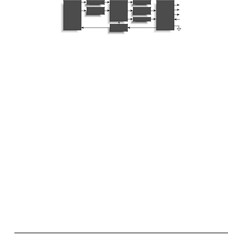
3.1 PRINCIPLE OF OPERATION
Method of detection is by a controlled rate of diffusion. Air and gas diffuse through a sintered stainless steel filter and a diffusion barrier. As oxygen is adsorbed into the electrolyte solution a current is generated between the cathode and anode electrodes. This current output rises with increases in oxygen concentration and reverses with lower concentrations. The quick response of the cell results in continuous monitoring of ambient air conditions.
Functional
Block
Diagram
Sensor |
Element |
Pre-Amp |
Temperature |
Compensation |
|
Display |
|
Relays Out |
|
|
|
|
Micro- |
Alarm & Fault |
|
Serial RS-485 Out |
processor |
Relays |
I/O Circuit |
Analog 4-20 mA Out |
|
|
||
|
|
Protection |
|
|
RS-485 & 4-20mA |
Power In |
|
|
|
||
Transmitter |
|
|
|
Power Supply |
|
|
|
3.2 APPLICATION
Model DM-634 MicroSafe™ sensors are designed to detect and monitor oxygen deficiency in ambient air in the range of 0-25%. Minimum sensitivity and scale resolution is 0.1%. Operating temperature range is -4° F. to +122° F. While the sensor is capable of operating outside these temperatures, performance specifications are verified within the limit.
3.2.1 Sensor Placement/Mounting
Sensor location should be reviewed by facility engineering and safety personnel. Area leak sources and perimeter mounting are typically used to determine number and location of sensors. The sensors are generally located 2 - 4 feet above grade.
3.2.2 Interference Data |
|
Methane |
100% = 0 |
Hydrocarbons |
100% = 0 |
Hydrogen |
100% = < -2% |
Carbon Monoxide |
20% = < -0.5% |
3.3 SPECIFICATIONS
Method of Detection
Air battery diffusion/adsorption
Electrical Classification
Class I; Groups B, C, D; Div. 1.
Response Time (T90)
T90 < 20 seconds
Clearing Time
90% < 20 seconds
Repeatability
±2% FS
Range
0-25% O2
Operating Temperature
-4° to +122° F
Accuracy
±2% FS
Sensor Warranty
2 year conditional
Detcon Model DM-634 Oxygen Sensor PG.5

Power Consumption
Normal operation = 28 mA (<3/4 watt); Full alarm = 85 mA (2 watts)
Output
3 relays (alarm 1, alarm 2, and fault) contact rated 5 amps @ 250 VAC, 5 amps @ 30 VDC; Linear 4-20 mA DC; RS-485 Modbus™
Input Voltage
22.5-28 VDC
3.4 OPERATING SOFTWARE
Operating software is menu listed with operator interface via the two magnetic program switches located under the face plate. The two switches are referred to as “PGM 1” and “PGM 2”. The menu list consists of 3 items which include sub-menus as indicated below. (Note: see the end of this manual for a complete software flow chart.)
01.Normal Operation
a)Current Status
02.Calibration Mode
a)Span
03.Program Menu
a)Program Status
b)Alarm 1 Level
c)Alarm 2 Level
d)Set Calibration Level
3.4.1Normal Operation
In normal operation, the display tracks the current status of the sensor and gas concentration and appears as: “20.9 % O2”. The mA current output corresponds to the monitoring level of 0-25% O2 = 4-20 mA.
3.4.2 Calibration Mode
Calibration mode allows for sensor span adjustments. “2-SPAN”
The default span adjustment setting is 20.9% which is the normal atmospheric concentration of O2. Span gas concentrations other than 20.9% may be used. Refer to section 3.4.3.4 for details. “AUTO SPAN”
3.4.3 Program Mode
The program mode provides a program status menu and allows for the adjustment of alarm set point levels and the programming of the calibration gas level setting.
3.4.3.1 Program Status
The program status scrolls through a menu that displays:
* The gas type, range of detection and software version number. The menu item appears as: “O2 0-25 V528J”
*The alarm set point level of alarm 1. The menu item appears as: “ALM1 SET @ xx.x%”
*The alarm firing direction of alarm 1. The menu item appears as: “ALM1 DESCENDING” or ascending.
*The alarm relay latch mode of alarm 1. The menu item appears as: “ALM1 NONLATCHING” or latching.
*The alarm relay energize state of alarm 1. The menu item appears as: “ALM1 DE-ENERGIZED” or energized.
*The alarm set point level of alarm 2. The menu item appears as: “ALM2 SET @ xx.x%”
*The alarm firing direction of alarm 2. The menu item appears as: “ALM2 DESCENDING” or ascending.
*The alarm relay latch mode of alarm 2. The menu item appears as: “ALM2 LATCHING” or nonlatching.
*The alarm relay energize state of alarm 2. The menu item appears as: “ALM2 DE-ENERGIZED” or energized.
*The alarm relay latch mode of the fault alarm. The menu item appears as: “FLT NONLATCHING” or latching.
*The alarm relay energize state of the fault alarm. The menu item appears as: “FLT ENERGIZED” or de-energized.
*The calibration gas level setting. The menu item appears as: “CalLevel @ xx.x%”
*Identification of the RS-485 ID number setting. The menu item appears as: “485 ID SET @ ##”
Detcon Model DM-634 Oxygen Sensor PG.6

* The estimated remaining sensor life. The menu item appears as: “SENSOR LIFE 100%”
3.4.3.2 Alarm 1 Level Adjustment
The alarm 1 level is adjustable from 2.5% to 22.5%. The menu item appears as: “SET ALM1 @ 19.5%”
3.4.3.3 Alarm 2 Level Adjustment
The alarm 2 level is adjustable from 2.5% to 22.5%. The menu item appears as: “SET ALM2 @ 17.5%”
3.4.3.4 Calibration Level Adjustment
The calibration level is adjustable from 15.0% to 25.0% O2. The menu item appears as: “CalLevel @ xx.x%”
3.5 INSTALLATION
Optimum performance of ambient air/gas sensor devices is directly relative to proper location and installation practice.
3.5.1 Field Wiring Table (4-20 mA output)
Detcon MicroSafe™ O2 sensor assemblies require three conductor connection between power supplies and host electronic controllers. Wiring designators are + (DC), – (DC) , and mA (sensor signal). Maximum single conductor resistance between sensor and controller is 10 ohms. Maximum wire size for termination in the sensor assembly terminal board is 14 gauge.
AWG |
Meters |
Feet |
20 |
240 |
800 |
18 |
360 |
1200 |
16 |
600 |
2000 |
14 |
900 |
3000 |
Note 1: This wiring table is based on stranded tinned copper wire and is designed to serve as a reference only. Note 2: Shielded cable may be required in installations where cable trays or conduit runs include high voltage lines or other sources of induced interference.
The RS-485 (if applicable) requires 24 gauge, two conductor, shielded, twisted pair cable between sensor and host PC. Use Belden part number 9841. Two sets of terminals are located on the connector board to facilitate serial loop wiring from sensor to sensor. Wiring designators are A & B (IN) and A & B (OUT).
3.5.2 Sensor Location
Selection of sensor location is critical to the overall safe performance of the product. Five factors play an important role in selection of sensor locations:
(1)Density of the gas to be detected
(2)Most probable leak sources within the industrial process
(3)Ventilation or prevailing wind conditions
(4)Personnel exposure
(5)Accessibility for routine maintenance
Density - Placement of sensors relative to the density of the target gas is such that sensors for the detection of heavier than air gases should be located within 2-4 feet of grade as these heavy gases will tend to settle in low lying areas. For gases lighter than air, sensor placement should be 4-8 feet above grade in open areas or in pitched areas of enclosed spaces.
Leak Sources - Most probable leak sources within an industrial process include flanges, valves, and tubing connections of the sealed type where seals may either fail or wear. Other leak sources are best determined by facility engineers with experience in similar processes.
Detcon Model DM-634 Oxygen Sensor PG.7
 Loading...