


Wireless Modbus™ and
4-20mA Transceiver
Model RXT-320
Operator’s Installation and Instruction Manual
 DETCON, Inc.
4055 Technology Forest Blvd.,
The Woodlands, Texas 77381
Ph.281.367.4100 / Fax 281.298.2868
www.detcon.com
August 2, 2012 • Document # 3588 • Revision 2.1

RXT-320 Wireless Modbus™
Page intentionally blank
Shipping Address: 4055 Technology Forest Blvd., The Woodlands Texas 77381
Mailing Address: P.O. Box 8067, The Woodlands Texas 77387-8067
Phone: 888.367.4286, 281.367.4100 • Fax: 281.292.2860 • www.detcon.com • sales@detcon.com
RXT-320 Wireless IM |
ii |

|
|
|
RXT-320 Wireless Modbus™ |
|
|
Table of Contents |
|
1.0 |
Introduction ........................................................................................................................................ |
1 |
|
1.1 |
Description ...................................................................................................................................... |
1 |
|
1.2 |
RXT-320 Wireless Radio................................................................................................................. |
2 |
|
1.3 |
Model 100 Terminal Board (Optional) ............................................................................................. |
3 |
|
1.4 |
Smart Battery Pack (Optional) ......................................................................................................... |
4 |
|
1.5 |
Quad Battery Charger (Optional) ..................................................................................................... |
5 |
|
1.6 |
Solar Panel (Optional) ..................................................................................................................... |
6 |
|
2.0 |
Installation .......................................................................................................................................... |
6 |
|
2.1 |
Guidelines for Safe Use ................................................................................................................... |
6 |
|
2.2 |
Mounting......................................................................................................................................... |
7 |
|
|
2.2.1 |
Remote Mounting..................................................................................................................... |
8 |
2.3 |
Wiring Connections / Functions..................................................................................................... |
12 |
|
|
2.3.1 |
VDC Power & VDC Return.................................................................................................... |
12 |
|
2.3.2 |
Modbus™ A & B.................................................................................................................... |
13 |
|
2.3.3 |
Alarm 0-3............................................................................................................................... |
13 |
|
2.3.4 |
4-20mA A & B........................................................................................................................ |
14 |
|
2.3.5 |
Serial Clock & Serial Data Line............................................................................................. |
15 |
|
2.3.6 |
Programming Data, Clock & Reset ........................................................................................ |
15 |
2.4 |
Model 100 Terminal Board Settings............................................................................................... |
15 |
|
3.0 |
Operation and Configuration........................................................................................................... |
16 |
|
3.1 |
Transparent Mode.......................................................................................................................... |
16 |
|
3.2 |
Master Configuration with Controller ............................................................................................ |
17 |
|
3.3 |
Slave Configuration with Sensor.................................................................................................... |
17 |
|
3.4 |
Slave Configuration with Alarm Station......................................................................................... |
17 |
|
3.5 |
Sleep Mode ................................................................................................................................... |
18 |
|
4.0 |
Modbus Communications................................................................................................................. |
18 |
|
4.1 |
General Modbus™ Description...................................................................................................... |
19 |
|
|
4.1.1 |
Modbus™ Exceptions ............................................................................................................ |
19 |
|
4.1.2 |
Modbus™ Broadcast Requests............................................................................................... |
20 |
4.2 |
Modbus™ Register Map & Description ......................................................................................... |
20 |
|
|
4.2.1 |
Register – Detcon Type .......................................................................................................... |
21 |
|
4.2.2 |
Register – Alarm Outputs ....................................................................................................... |
21 |
|
4.2.3 |
Register – 4-20mA Reading.................................................................................................... |
22 |
|
4.2.4 |
Register – Battery Info ........................................................................................................... |
22 |
|
4.2.5 |
Register – uC Version ............................................................................................................ |
22 |
|
4.2.6 |
Register – Sleep Time............................................................................................................. |
22 |
|
4.2.7 |
Register – Control.................................................................................................................. |
23 |
|
4.2.8 |
Register – Status .................................................................................................................... |
23 |
|
4.2.9 |
Register – Address Switch ...................................................................................................... |
23 |
|
4.2.10 Register – Timestamp............................................................................................................. |
24 |
|
5.0 |
Troubleshooting Guide ..................................................................................................................... |
24 |
|
6.0 |
Warranty........................................................................................................................................... |
24 |
|
7.0 |
Specifications .................................................................................................................................... |
25 |
|
7.1 |
Spare Parts .................................................................................................................................... |
26 |
7.2 |
Revision Log ................................................................................................................................. |
27 |
RXT-320 Wireless IM |
iii |
|

RXT-320 Wireless Modbus™ |
|
Table of Figures |
|
Figure 1 RXT-320 Wireless Transceiver Assembly...................................................................................... |
1 |
Figure 2 Typical Wireless Layout ................................................................................................................ |
2 |
Figure 3 Mesh Network Topology .............................................................................................................. |
3 |
Figure 4 Model 100 Terminal Board............................................................................................................ |
4 |
Figure 5 Smart Battery Pack ........................................................................................................................ |
4 |
Figure 6 Quad Battery Charger .................................................................................................................... |
5 |
Figure 7 Solar Panel .................................................................................................................................... |
6 |
Figure 8 RXT-320 Approval Label ............................................................................................................. |
6 |
Figure 9 RXT-320 Wireless Transceiver w/Battery Assembly and Mounting Dimensions ........................... |
8 |
Figure 10 RXT-320 Wireless Transceiver Remote Mounting ...................................................................... |
9 |
Figure 11 Wiring Diagram for Remote RXT-320 Transceiver Mounting...................................................... |
10 |
Figure 12 Internal Alarm Output Circuit ..................................................................................................... |
14 |
Figure 13 Up to two Sensors using two 4-20mA Interfaces ......................................................................... |
14 |
Figure 14 Model 100 Terminal Board Rotary Switches................................................................................ |
15 |
Figure 16 Modbus™ Frame Format............................................................................................................. |
19 |
|
List of Tables |
|
Table 1 Extension Cable Wire Identification................................................................................................ |
12 |
|
Table 2 RXT-320 Transceiver Wire Identification ....................................................................................... |
12 |
|
Table 3 Wire Gauge vs. Distance................................................................................................................. |
13 |
|
Table 4 Model 100 Terminal Board Jumper Settings.................................................................................... |
15 |
|
Table 5 |
RXT-320 Addressing and Operational Modes ................................................................................. |
16 |
Table 6 Exception Codes ............................................................................................................................. |
19 |
|
Table 7 |
RXT-320 Register Map................................................................................................................... |
21 |
Table 8 |
RXT-320 Secondary Alarm Output Register Map ........................................................................... |
21 |
RXT-320 Wireless IM |
iv |
RXT-320 Wireless Modbus™
1.0Introduction
1.1Description
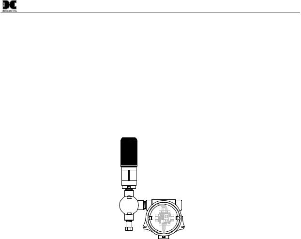
The RXT-320 wireless transceiver is designed to take Modbus™ communication between devices to a wireless platform. The transceiver connects directly to a Modbus™ device and transfers Modbus™ data to/from the device through the transceiver’s wireless radio. The transceiver broadcasts this information throughout a wireless network of other RXT-320 transceivers connected to Modbus™ devices thus creating a seamless network of Modbus™ devices that need not be physically connected in any way. The RXT-320 transceiver can be mounted to a J-Box/condulet with an optional Model 100 Terminal Board that allows for power, data connections and addressing enabling it to interface with a wide range of devices. Refer to Figure 1 for a typical wireless transceiver assembly.
RXT-320 Wireless Transceiver
J-Box w/
Model 100
Terminal Board
34" NPT T-Outlet
Box w/Drain
Figure 1 RXT-320 Wireless Transceiver Assembly
The RXT-320 wireless transceiver provides interfaces for 4-20mA devices as well as Modbus™ devices. There can be up to 32 devices total on a single wireless network and a transceiver can support more than one device. Additionally, there can be up to 32 RXT-320 transceivers in a single wireless network. The RXT-320 transceiver’s radio operates at 2.4GHz and conforms to non-licensed radio frequency appliance usage around the world. Wireless network integrity and security is accomplished using Direct Sequence Spread Spectrum (DSSS) wireless mesh technology. Each transceiver is capable of functioning as a router or repeater for all other RXT-320 transceivers on the network. This means that data between devices can “hop” through neighboring transceivers to communicate with each other thereby widening network access points. This unique and innovative technology is designed to create a robust network that automatically routes around congestion and line-of-sight obstacles while improving throughput as the number of devices increases.
The RXT-320 transceiver comes equipped with an RS-485 port for communication with local Modbus™ devices. As with normal Modbus™ operation, there can only be one Modbus™ master and all other devices are considered as slave devices. Each device must have a unique Modbus™ address. Each transceiver is also assigned a Modbus™ address via the Model 100 Terminal Board which has two rotary switches used to set the address.
The Modbus™ master unit’s transceiver is responsible for broadcasting requests and receiving slave device responses. Slave device transceivers receive these broadcasts and pass the Modbus™ information on to the slave devices attached via their local Modbus™ interface. When a response is generated by the slave device, it sends it back to its transceiver through the Modbus™ interface. The transceiver then broadcasts that
RXT-320 Wireless IM |
Rev. 2.1 |
Page 1 of 27 |
RXT-320 Wireless Modbus™
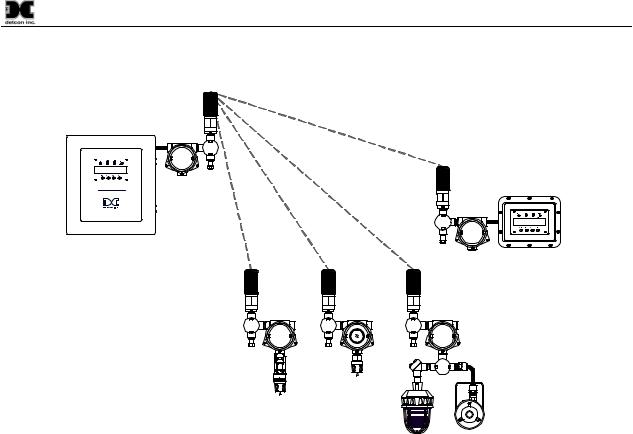
information back to the master unit’s transceiver, which then places that information on the bus for the master unit.
Modbus Master
Control Unit
|
Remote Monitor |
Model X40-N4X |
Unit |
Muiti-Channel Gas Detection Control System |
Modbus Slave
Devices
Figure 2 Typical Wireless Layout
The transceiver provides for the following features/connectivity:
|
Modbus™ Interface: |
Master or Slave connection for up to 32 Modbus™ devices on the network |
|
Wireless Radio: |
IEEE 802.15.4, Mesh Topology, 16 RF channels, DSSS encoding, 2.4GHz |
|
4-20mA Inputs: |
Two inputs available to connect two 4-20mA sensors/devices |
|
Alarm Outputs: |
4 low current outputs capable of driving relays for audible/visual alarms |
|
Battery Operation: |
Low Power Sleep and battery life available from Detcon Smart Battery Pack |
|
Addressable: |
For Modbus™ access to RXT-320 control and status (set through term board) |
|
Multiple Modes: |
Operational mode (Transparent, Master, Slave, Alarm Station) based on |
|
|
address configuration |
1.2RXT-320 Wireless Radio
The RXT-320 transceivers utilize radios based upon the IEEE 802.15.4 standard that operate at 2.4 GHz using DSSS encoding for robustness. DSSS was initially used by the military to resist jamming but later was widely adopted for wireless implementations since it was robust in noisy environments. DSSS transmits data across a wider frequency range than the actual frequency range required for the information. This operation minimizes cross talk and interference from other transceivers and is less susceptible to noise from other sources.
The IEEE 802.15.4 defines 16 separate RF Channels that can be used in the 2.4 GHz range. The default channel is 1 but can be change if there is RF interference or if there is an existing network using that channel. Transceivers will only respond to other transceivers with the same RF Channel.
RXT-320 Wireless IM |
Rev. 2.1 |
Page 2 of 27 |

RXT-320 Wireless Modbus™
NOTE: If there are multiple Modbus™ networks in the same vicinity each system must reside on a different RF Channel to keep data from one appearing on the other.
The 802.15.4 standard also implements a mesh network allowing any RXT-320 transceiver to relay or repeat data between adjacent neighbors. This makes the network very robust and provides the following immediate benefits:
Allows re-routing of data in case of loss of a transceiver
Allows re-routing around wireless obstacles
Longer distances between transceivers because data can “hop” from one transceiver to the next
Included in sensor, controller and alarm station transceivers
RXT-320 transceivers can be deployed with less concern about physical location
Figure 3 Mesh Network Topology
1.3Model 100 Terminal Board (Optional)
The RXT-320 wireless transceiver can be ordered with an optional Model 100 Terminal Board mounted in a condulet/J-Box (See Figure 4). The terminal board includes connector plugs for the following:
J1 6-Pin Phoenix Connector – RXT-320 Wireless Transceiver
J2 5-Pin Phoenix Connector – Slave Device/Master Controller/Remote Monitor J3 6-Pin Connector – RXT Programming Port (Detcon Factory use only)
J4 3-Pin Phoenix Connector – Model 100 Loop Powered LED display
J5 3-Pin Phoenix Connector – 7-30VDC External power source or 24VDC Solar Panel
J6 8-Pin Beau Connector – 12VDC Battery Power (Use only Detcon’s Smart Battery Pack) J7 3-Pin Phoenix Connector – Spare Modbus™ Connection
J8 3-Pin Phoenix Connector – RXT Programming Interface to Wireless Transceiver
Refer to section 2.4 for more information about the setup of the Model 100 Terminal Board.
RXT-320 Wireless IM |
Rev. 2.1 |
Page 3 of 27 |

WIRELESS
|
|
|
|
AIN1 |
W/BK |
W/BN |
W/BU |
W/GN |
W/V |
MODBUS OUT |
J8 |
|
|
|
|
|
|||
|
|
|
|
|
|
||||
(WIRELESS) |
|
|
|
|
|
|
|||
B |
A |
GND |
24V |
SW2 |
|
|
|
|
|
|
|
|
|
|
|
|
|
|
|
|
|
|
J1 |
|
|
|
|
|
|
|
|
|
J4 |
SW1 |
|
|
|
|
|
|
|
|
|
|
|
|
|
|
|
24V |
GND |
A |
B |
|
|
|
|
|
|
|
MODBUS IN |
|
|
|
|
|
|
||
|
|
|
|
J5 |
|
|
|
|
|
|
|
|
TERM |
|
|
|
|
|
|
|
|
PROGRAM |
PWR |
GND |
SCL |
SDA |
SP1 |
SP2 |
|
|
|
|
|
||||||
L9 DISPLAY
RXT-320 Wireless Modbus™
WIRELESS
PROGRAM
J2
POWER IN (SOLAR)
AIN2 |
MA |
GND |
PWR |
J7
J6
24V |
GND |
A |
B |
SENSOR
JP1
Figure 4 Model 100 Terminal Board
1.4Smart Battery Pack (Optional)
The RXT-320 transceiver can also be powered by an optional battery pack that enables it to be remotely mounted without the need for any cables because of its wireless operation. The available battery pack is Detcon’s plug-in Smart Battery Pack which provides an output of 12VDC (See Figure 5). If installed, the RXT-320 transceiver will detect the battery and will continuously query the battery pack for remaining battery life. The battery pack consists of rechargeable Lithium-Ion batteries and is equipped with integrated safety electronics that include fuel gauge, voltage, current and temperature monitoring circuits. This “smart” circuitry continuously monitors the battery’s condition and reports critical status information to the wireless transceiver via the Modbus™ registers. The battery pack is designed to plug onto an 8-pin Beau connector on the Model 100 Terminal Board and should not be exposed to outside elements without being housed and protected. Only Detcon products specifically designed to utilize these battery packs should be used. Operating periods before recharge will vary based on devices attached along with the transceiver and the usage of those devices, but can be as long as 2-3 months and battery life can be up to 5 years before battery pack replacement is required. Improper use of the battery pack may be hazardous to personnel or the environment and will void the warranty.
Figure 5 Smart Battery Pack
NOTE: The RXT-320 wireless transceiver can also be powered by a customer provided external DC power source. Refer to section 2.3.1 for more details.
RXT-320 Wireless IM |
Rev. 2.1 |
Page 4 of 27 |

RXT-320 Wireless Modbus™
1.5Quad Battery Charger (Optional)
Detcon’s Smart Battery Pack can be charged as needed using Detcon’s optional Quad Battery Charger which can charge up to four battery packs at one time. The Quad Battery Charger comes with a plug-in AC/DC adapter that plugs into a standard 120VAC outlet for power. The DC end of the adapter plugs into the DC power jack of the charger providing 24VDC. The Quad Battery Charger has four charging ports, each with 8- pin Beau connectors for battery pack connection. The ports and connectors are keyed to prevent incorrect positioning and connection. Each port has its own “FAULT” LED indicator and “CHARGE” LED indicator and will display either a red light or green light depending on the status of each battery being charged. Charging times will vary depending on the charge state of each battery pack, but a full charge of a depleted battery pack can take up to 24 hours.
Figure 6 Quad Battery Charger
When first powered on and with no battery packs connected to the charger, all the LED indicators on the Quad Charger should be green. When a battery pack is seated into a charging port, the “CHARGE” LED will change from green to red indicating the battery pack is not sufficiently charged. Once fully charged, the LED will change from red to green and the battery pack is ready to be used.
The “Fault” LED should remain green indicating that there are no problems with the battery pack or charging port. If the “Fault” LED turns red with the battery pack connected, then there is a problem or issue with the battery pack and it should not be used and be removed immediately. If the “Fault” LED turns red without a battery pack connected to the charge port, then there is a problem or issue with the port and that port should no longer be used.
Battery packs can remain connected to the charger even after a full charge indication (Green “Charge” LED) is shown due to the protection circuitry of the battery pack which prevents any overcharging issues.
RXT-320 Wireless IM |
Rev. 2.1 |
Page 5 of 27 |
RXT-320 Wireless Modbus™
1.6Solar Panel (Optional)
Detcon also offers an optional solar panel to be used in conjunction with the Smart Battery Pack. It provides 24VDC output and connects to the J5 connector of the Model 100 Terminal Board. This option enables continuous operation of the wireless transceiver and charging of the battery pack eliminating the need for external recharging. It is an ideal choice for virtually any area with sufficient daily average sunlight. Since the solar panel is considered and external power supply, a special conduit installation will be required.
If the optional solar panel is installed, consideration should be given to position the panel where the most sunlight is available. The solar panel can be mounted remotely to allow for maximum sunlight exposure. If necessary, a sunshade can be used for the wireless transceiver assembly to help reduce its operating temperature.
Figure 7 Solar Panel
2.0Installation
2.1Guidelines for Safe Use
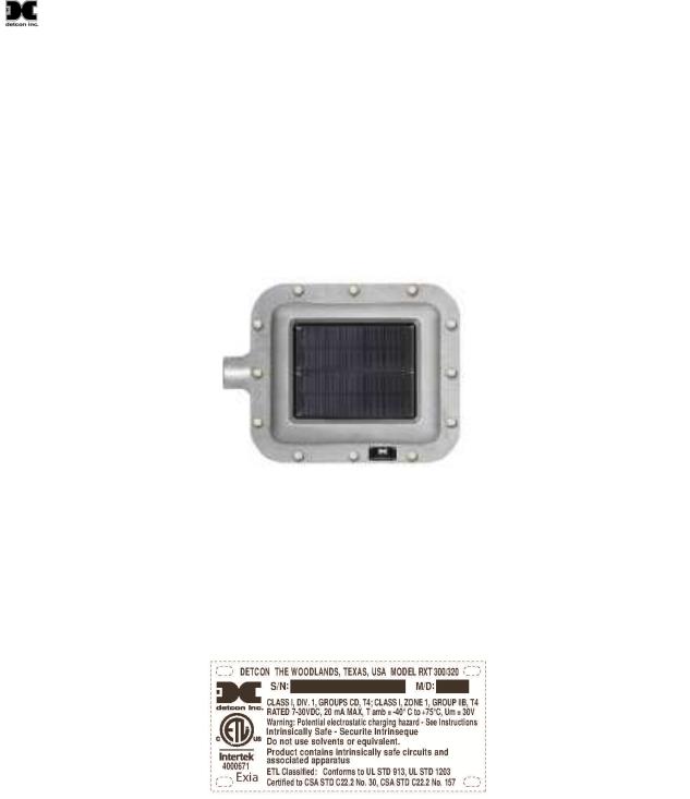
1.Install unit only in areas with classifications matching with those described on the approval label. Follow all warnings listed on the label.
Figure 8 RXT-320 Approval Label
2.Do not use in areas containing air saturation levels of Acetic Acid, Acetone, Ammonium Hydroxide, Fuel C, Diethyl Ether, Ethyl Acetate, Ethylene Dichloride, Furfural, N-Hexane, MEK, Methanol, 2- Nitropropane, or Toluene.
3.Ensure that the transceiver is properly threaded into a suitable explosion-proof rated junction box with a female ¾” NPT threaded connection. The sensor should be threaded up at least 5 full turns until tight. Avoid use of Teflon Tape, or any type of non-conductive pipe thread coating on the NPT threaded connection.
RXT-320 Wireless IM |
Rev. 2.1 |
Page 6 of 27 |
 Loading...