


Denon DVD-3800BDCI Service Manual
Ver. 1
SERVICE MANUAL
MODEL JP E3 E2 EK E2A E1C E1K EUT
DVD-3800BDCI
BLU-RAY DISC/DVD VIDEO PLAYER
3
注 意
サービスをおこなう前に、このサービスマニュアル
を必ずお読みください。本機は、火災、感電、けが
などに対する安全性を確保するために、さまざまな
配慮をおこなっており、また法的には「電気用品安
全法」にもとづき、所定の許可を得て製造されてお
ります。従ってサービスをおこなう際は、これらの
安全性が維持されるよう、このサービスマニュアル
に記載されている注意事項を必ずお守りください。
●
For purposes of improvement, specifications and
design are subject to change without notice.
●
Please use this service manual with referring to the
operating instructions without fail.
●
Some illustrations using in this service manual are
slightly different from the actual set.
e
Denon Brand Company, D&M Holdings lnc.
●
本機の仕様は性能改良のため、予告なく変更すること
があります。
●
補修用性能部品の保有期間は、製造打切後 8 年です。
●
修理の際は、必ず取扱説明書を参照の上、作業を行っ
てください。
●
本文中に使用しているイラストは、説明の都合上現物
と多少異なる場合があります。
X0380 V.01 DE/CDM 0803

SAFETY PRECAUTIONS
The following check should be performed for the continued protection of the customer and service technician.
LEAKAGE CURRENT CHECK
Before returning the unit to the customer, make sure you make either (1) a leakage current check or (2) a line to chassis
resistance check. If the leakage current exceeds 0.5 milliamps, or if the resistance from chassis to either side of the
power cord is less than 460 kohms, the unit is defective.
LASER RADIATION
Caution - Class 1M visible and invisible laser radiation when open.
Do not view directly with optical instruments.
CAUTION
Please heed the points listed below during servicing and inspection.
◎ Heed the cautions!
Spots requiring particular attention when servicing, such
as the cabinet, parts, chassis, etc., have cautions indicated
on labels or seals. Be sure to heed these cautions and the
cautions indicated in the handling instructions.
◎ Caution concerning electric shock!
(1) An AC voltage is impressed on this set, so touching in-
ternal metal parts when the set is energized could
cause electric shock. Take care to avoid electric shock,
by for example using an isolating transformer and
gloves when servicing while the set is energized, unplugging the power cord when replacing parts, etc.
(2)There are high voltage parts inside. Handle with extra
care when the set is energized.
◎ Caution concerning disassembly and
assembly!
Though great care is taken when manufacturing parts from
sheet metal, there may in some rare cases be burrs on the
edges of parts which could cause injury if fingers are
moved across them. Use gloves to protect your hands.
◎ Inspect for safety after servicing!
Check that all screws, parts and wires removed or disconnected for servicing have been put back in their original positions, inspect that no parts around the area that has been
serviced have been negatively affected, conduct an insulation check on the external metal connectors and between
the blades of the power plug, and otherwise check that
safety is ensured.
(Insulation check procedure)
Unplug the power cord from the power outlet, disconnect
the antenna, plugs, etc., and turn the power switch on. Using a 500V insulation resistance tester, check that the insulation resistance between the terminals of the power
plug and the externally exposed metal parts (antenna terminal, headphones terminal, microphone terminal, input
terminal, etc.) is 1MΩ or greater. If it is less, the set must
be inspected and repaired.
CAUTION
Concerning important safety
parts
◎ Only use designated parts!
The set's parts have specific safety properties (fire resistance, voltage resistance, etc.). For replacement parts, be
sure to use parts which have the same properties. In particular, for the important safety parts that are marked z on
wiring diagrams and parts lists, be sure to use the designated parts.
◎ Be sure to mount parts and arrange
the wires as they were originally!
For safety reasons, some parts use tape, tubes or other insulating materials, and some parts are mounted away from
the surface of printed circuit boards. Care is also taken with
the positions of the wires inside and clamps are used to
keep wires away from heating and high voltage parts, so
be sure to set everything back as it was originally.
DVD-3800BDCI
Many of the electric and structural parts used in the set
have special safety properties. In most cases these properties are difficult to distinguish by sight, and using replacement parts with higher ratings (rated power and
withstand voltage) does not necessarily guarantee that
safety performance will be preserved. Parts with safety
properties are indicated as shown below on the wiring diagrams and parts lists is this service manual. Be sure to replace them with parts with the designated part number.
(1) Schematic diagrams ... Indicated by the z mark.
(2) Parts lists ... Indicated by the z mark.
Using parts other than the designated
parts could result in electric shock, fires or
other dangerous situations.
2
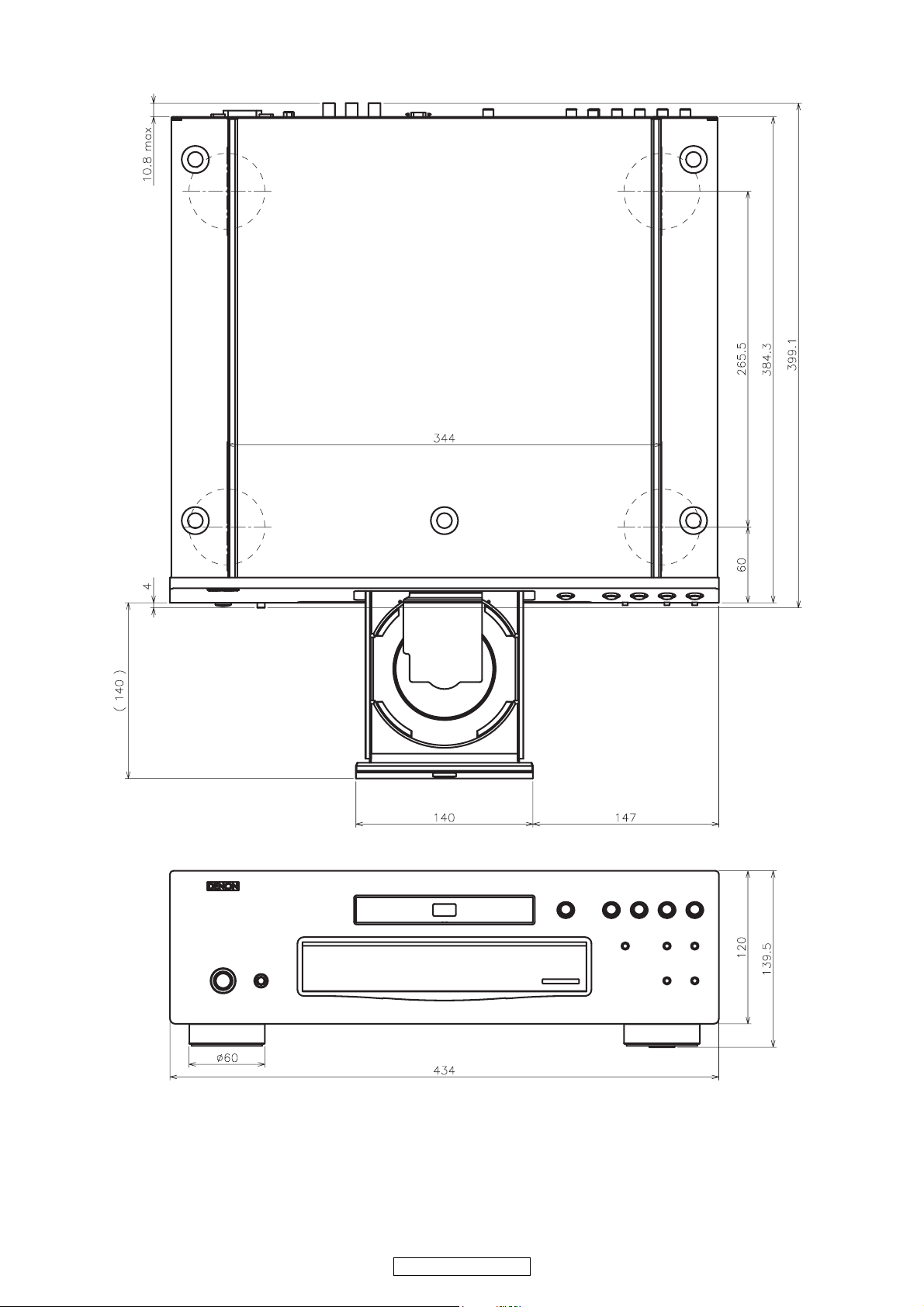
DIMENSION
3
DVD-3800BDCI

WIRE ARRANGEMENT
If wire bundles are untied or moved to perform adjustment or parts replacement etc., be sure to rearrange
them neatly as they were originally bundled or placed afterward.
Otherwise, incorrect arrangement can be a cause of noise generation.
Wire arrangement viewed from the top
4
DVD-3800BDCI
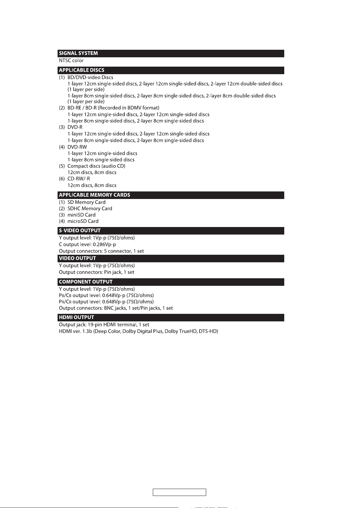
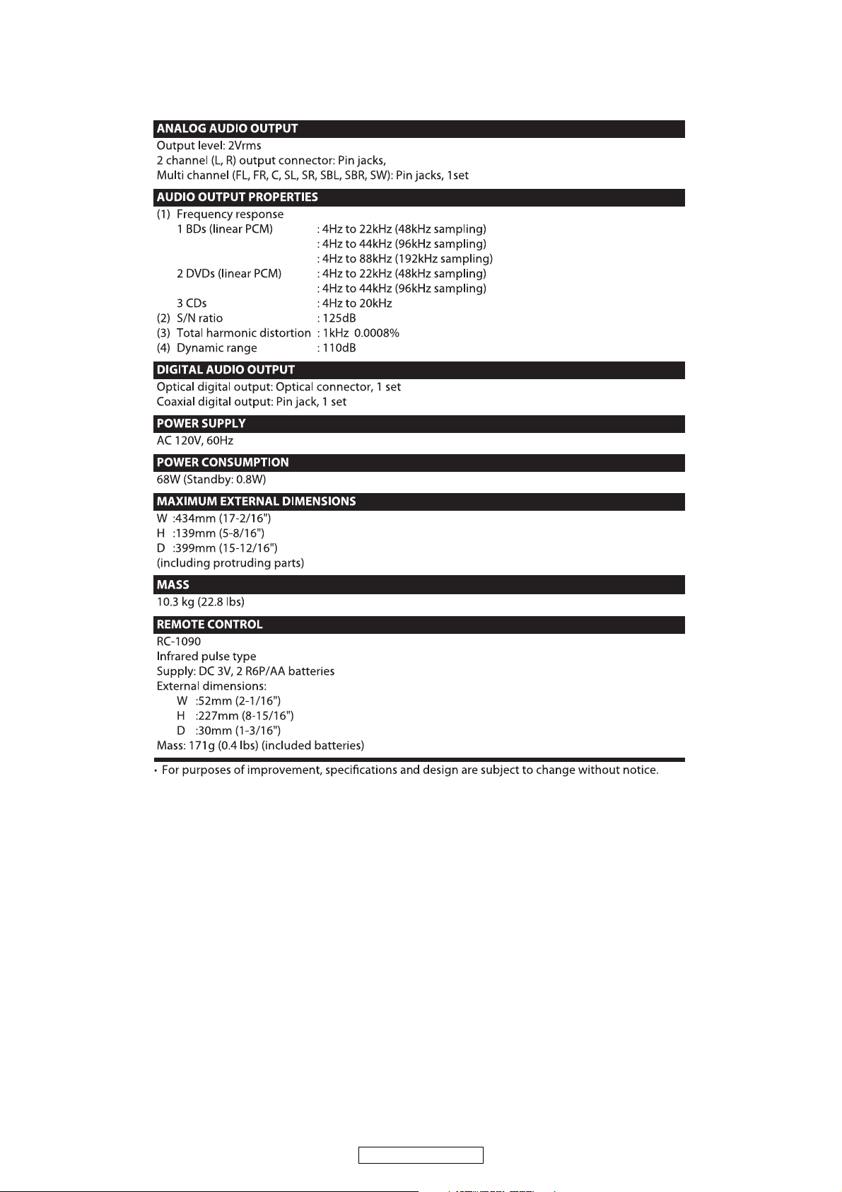
SPECIFICATIONS
5
DVD-3800BDCI
6
DVD-3800BDCI
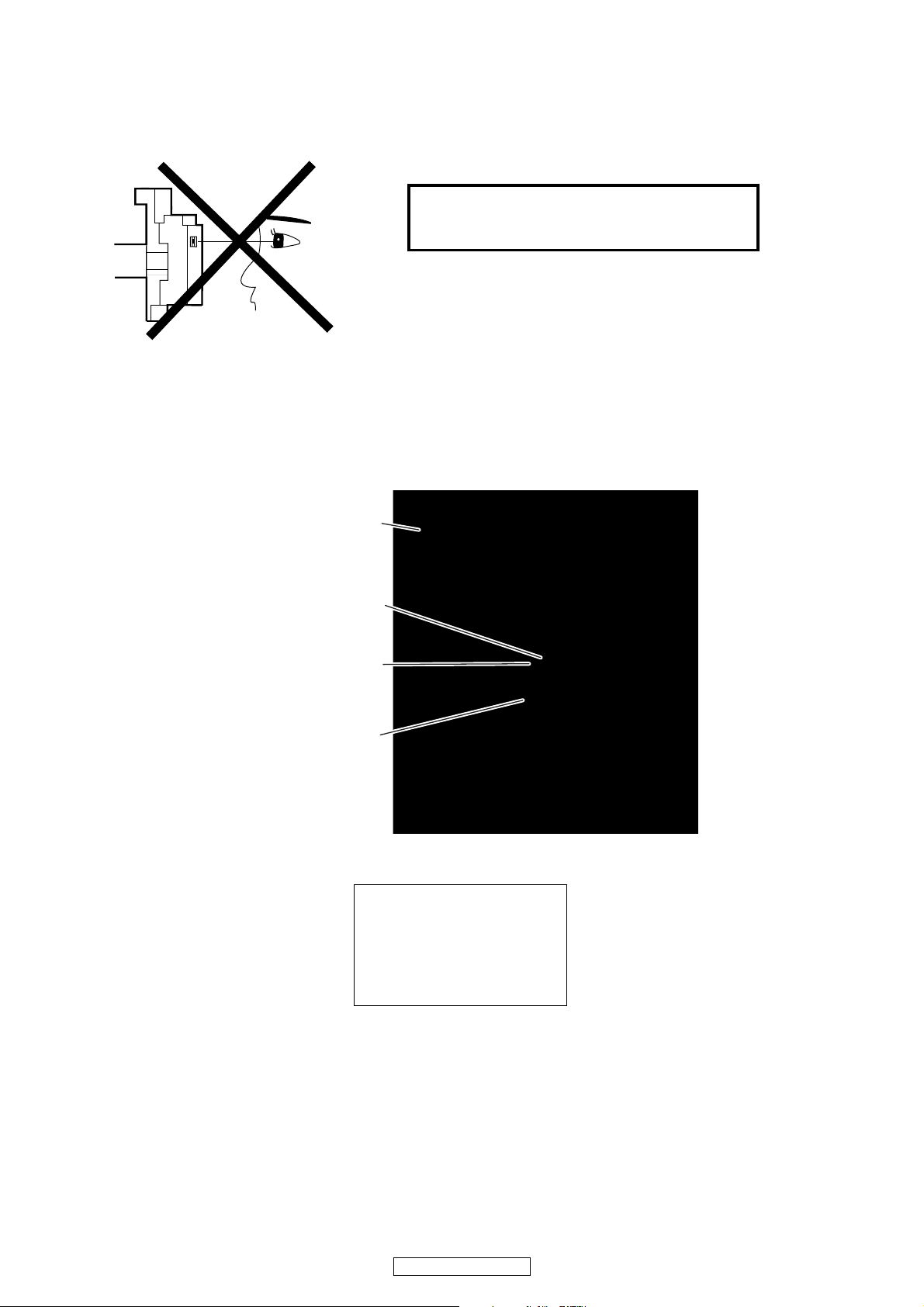
LASER BEAM SAFETY PRECAUTIONS
This BD player uses a pickup that emits a laser beam.
Do not look directly at the laser beam coming
from the pickup or allow it to strike against your
skin.
The laser beam is emitted from the location shown in the figure. When checking the laser diode, be sure to keep
your eyes at least 30 cm away from the pickup lens when the diode is turned on. Do not look directly at the laser
beam.
CAUTION: Use of controls and adjustments, or doing procedures other than those specified herein, may result in
hazardous radiation exposure.
Drive Mechanism Assembly
Laser Beam Radiation
Laser Pickup
Turntable
WHEN OPEN. DO NOT
Location: Top of BD mechanism.
CAUTION
LASER RADIATION
STARE INTO BEAM.
7
DVD-3800BDCI
Safety Check after Servicing
Examine the area surrounding the repaired location for damage or deterioration. Observe that screws, parts, and
wires have been returned to their original positions. Afterwards, do the following tests and confirm the specified
values to verify compliance with safety standards.
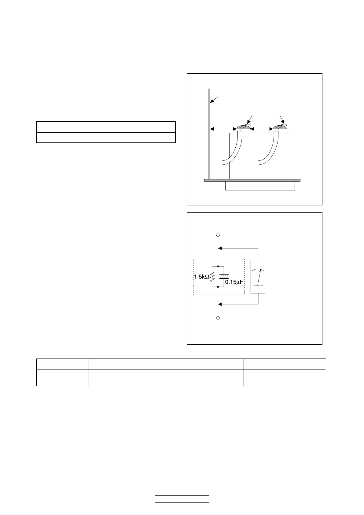
1. Clearance Distance
When replacing primary circuit components, confirm
specified clearance distance (d) and (d’) between
soldered terminals, and between terminals and
surrounding metallic parts. (See Fig. 1)
Table 1: Ratings for selected area
Chassis or Secondary Conductor
Primary Circuit
AC Line Voltage Clearance Distance (d), (d’)
120 V ≥ 3.2 mm (0.126 inches)
Note: This table is unofficial and for reference only. Be
sure to confirm the precise values.
2. Leakage Current Test
Confirm the specified (or lower) leakage current
between B (earth ground, power cord plug prongs) and
externally exposed accessible parts (RF terminals,
antenna terminals, video and audio input and output
terminals, microphone jacks, earphone jacks, etc.) is
lower than or equal to the specified value in the table
below.
Measuring Method (Power ON):
Insert load Z between B (earth ground, power cord plug
prongs) and exposed accessible parts. Use an AC
voltmeter to measure across the terminals of load Z.
See Fig. 2 and the following table.
d' d
Fig. 1
Exposed Accessible Part
Z
AC Voltmeter
(High Impedance)
Earth Ground
B
Power Cord Plug Prongs
Table 2: Leakage current ratings for selected areas
AC Line Voltage Load Z Leakage Current (i) Earth Ground (B) to:
120 V
Note: This table is unofficial and for reference only. Be sure to confirm the precise values.
0.15 μF CAP. & 1.5 kΩ RES.
Connected in parallel
i ≤ 0.5 mA Peak Exposed accessible parts
8
DVD-3800BDCI
Fig. 2
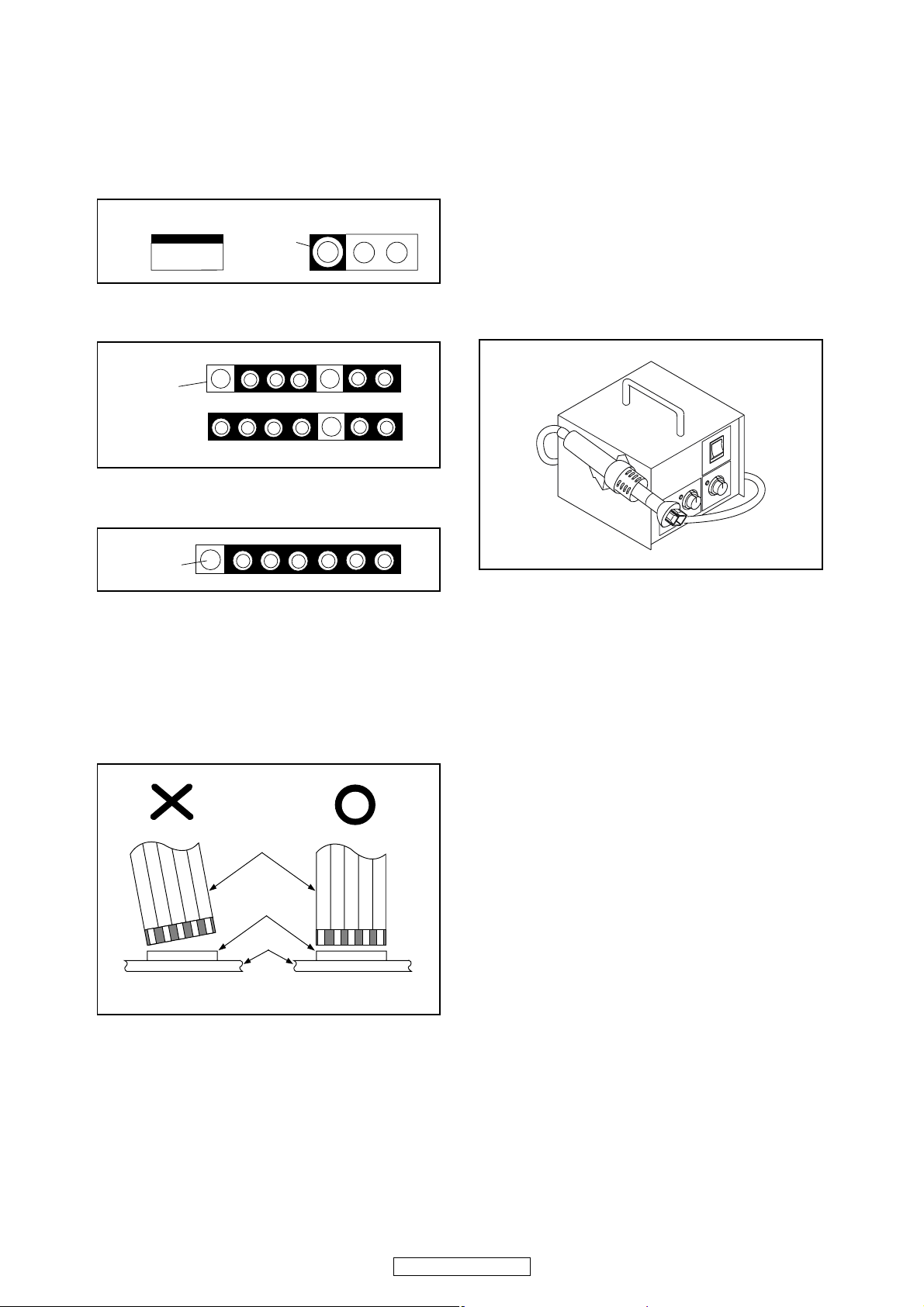
STANDARD NOTES FOR SERVICING
Circuit Board Indications
1. The output pin of the 3 pin Regulator ICs is
indicated as shown.
Top View
Out
2. For other ICs, pin 1 and every fifth pin are
indicated as shown.
Pin 1
3. The 1st pin of every male connector is indicated as
shown.
Pin 1
Input
In
Bottom View
5
10
Pb (Lead) Free Solder
When soldering, be sure to use the Pb free solder.
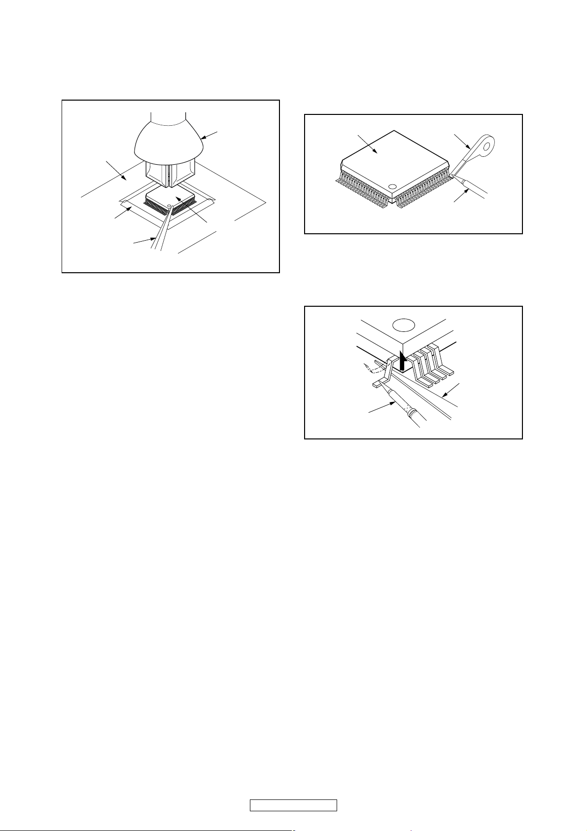
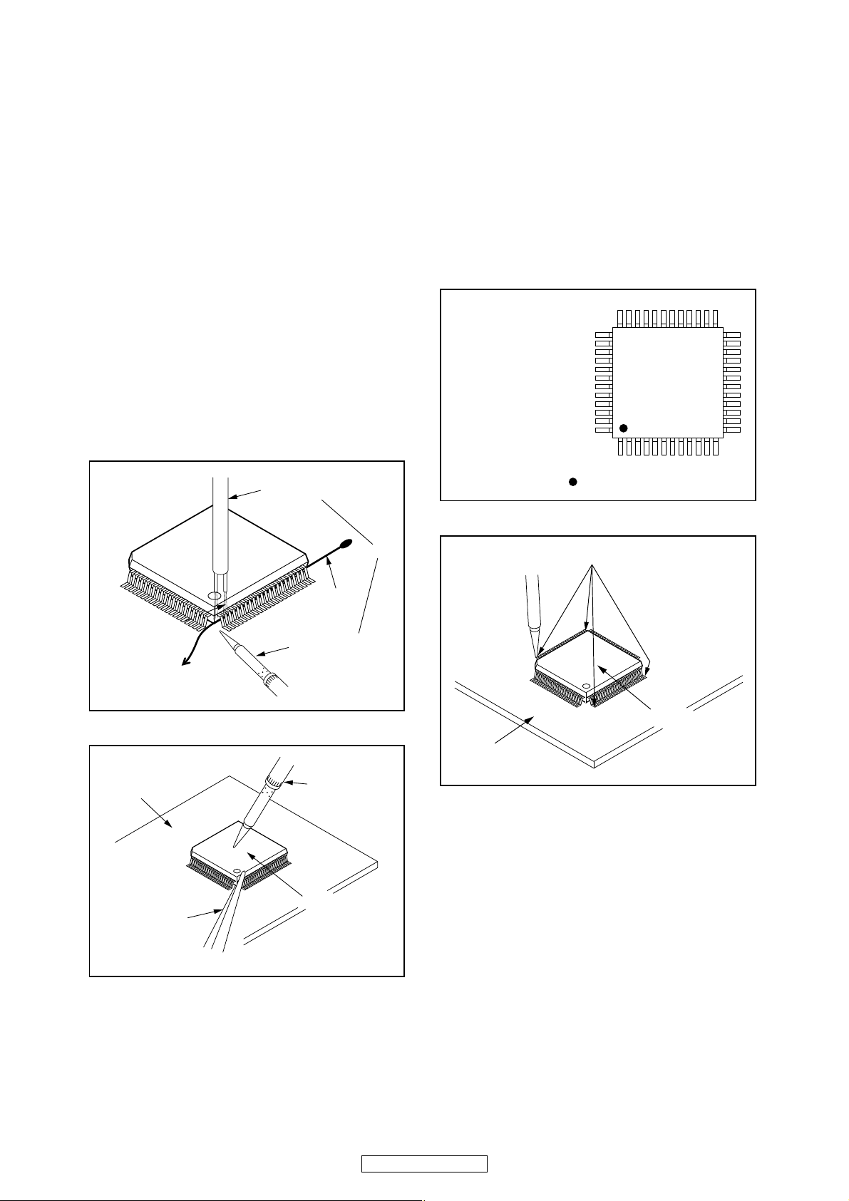
How to Remove / Install Flat Pack-IC
1. Removal
With Hot-Air Flat Pack-IC Desoldering Machine:
1. Prepare the hot-air flat pack-IC desoldering
machine, then apply hot air to the Flat Pack-IC
(about 5 to 6 seconds). (Fig. S-1-1)
Fig. S-1-1
Instructions for Connectors
1. When you connect or disconnect the FFC (Flexible
Foil Connector) cable, be sure to first disconnect
the AC cord.
2. FFC (Flexible Foil Connector) cable should be
inserted parallel into the connector, not at an
angle.
FFC Cable
Connector
CBA
* Be careful to avoid a short circuit.
2. Remove the flat pack-IC with tweezers while
applying the hot air.
3. Bottom of the flat pack-IC is fixed with glue to the
CBA; when removing entire flat pack-IC, first apply
soldering iron to center of the flat pack-IC and heat
up. Then remove (glue will be melted). (Fig. S-1-6)
4. Release the flat pack-IC from the CBA using
tweezers. (Fig. S-1-6)
CAUTION:
1. The Flat Pack-IC shape may differ by models. Use
an appropriate hot-air flat pack-IC desoldering
machine, whose shape matches that of the Flat
Pack-IC.
2. Do not supply hot air to the chip parts around the
flat pack-IC for over 6 seconds because damage
to the chip parts may occur. Put masking tape
around the flat pack-IC to protect other parts from
damage. (Fig. S-1-2)
9
DVD-3800BDCI
3. The flat pack-IC on the CBA is affixed with glue, so
be careful not to break or damage the foil of each
pin or the solder lands under the IC when
removing it.
With Soldering Iron:
1. Using desoldering braid, remove the solder from
all pins of the flat pack-IC. When you use solder
flux which is applied to all pins of the flat pack-IC,
you can remove it easily. (Fig. S-1-3)
CBA
Masking
Tape
Tweezers
Hot-air
Flat Pack-IC
Desoldering
Machine
Flat Pack-IC
Fig. S-1-2
Flat Pack-IC
2. Lift each lead of the flat pack-IC upward one by
one, using a sharp pin or wire to which solder will
not adhere (iron wire). When heating the pins, use
a fine tip soldering iron or a hot air desoldering
machine. (Fig. S-1-4)
Desoldering Braid
Soldering Iron
Fig. S-1-3
Sharp
Pin
Fine Tip
Soldering Iron
3. Bottom of the flat pack-IC is fixed with glue to the
CBA; when removing entire flat pack-IC, first apply
soldering iron to center of the flat pack-IC and heat
up. Then remove (glue will be melted). (Fig. S-1-6)
4. Release the flat pack-IC from the CBA using
tweezers. (Fig. S-1-6)
Fig. S-1-4
10
DVD-3800BDCI
With Iron Wire:
1. Using desoldering braid, remove the solder from
all pins of the flat pack-IC. When you use solder
flux which is applied to all pins of the flat pack-IC,
you can remove it easily. (Fig. S-1-3)
2. Affix the wire to a workbench or solid mounting
point, as shown in Fig. S-1-5.
3. While heating the pins using a fine tip soldering
iron or hot air blower, pull up the wire as the solder
melts so as to lift the IC leads from the CBA
contact pads as shown in Fig. S-1-5.
4. Bottom of the flat pack-IC is fixed with glue to the
CBA; when removing entire flat pack-IC, first apply
soldering iron to center of the flat pack-IC and heat
up. Then remove (glue will be melted). (Fig. S-1-6)
5. Release the flat pack-IC from the CBA using
tweezers. (Fig. S-1-6)
Note: When using a soldering iron, care must be
taken to ensure that the flat pack-IC is not
being held by glue. When the flat pack-IC is
removed from the CBA, handle it gently
because it may be damaged if force is applied.
Hot Air Blower
2. Installation
1. Using desoldering braid, remove the solder from
the foil of each pin of the flat pack-IC on the CBA
so you can install a replacement flat pack-IC more
easily.
2. The “●” mark on the flat pack-IC indicates pin 1.
(See Fig. S-1-7.) Be sure this mark matches the 1
on the PCB when positioning for installation. Then
presolder the four corners of the flat pack-IC. (See
Fig. S-1-8.)
3. Solder all pins of the flat pack-IC. Be sure that
none of the pins have solder bridges.
Example :
Pin 1 of the Flat Pack-IC
is indicated by a " " mark.
Fig. S-1-7
To Solid
Mounting Point
CBA
Tweezers
Iron Wire
Soldering Iron
Fig. S-1-5
Fine Tip
Soldering Iron
Flat Pack-IC
or
Presolder
Flat Pack-IC
CBA
Fig. S-1-8
Fig. S-1-6
DVD-3800BDCI
11
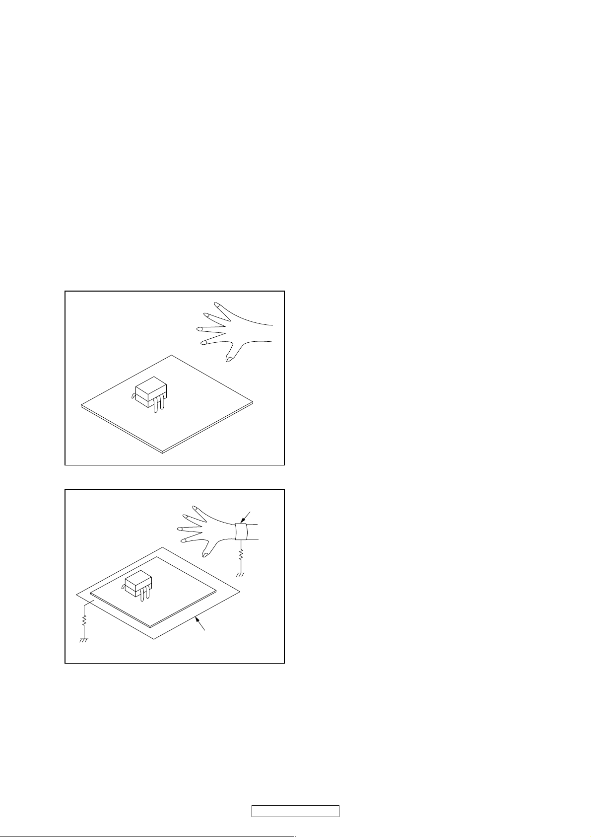
Instructions for Handling Semiconductors
Electrostatic breakdown of the semi-conductors may
occur due to a potential difference caused by
electrostatic charge during unpacking or repair work.
1. Ground for Human Body
Be sure to wear a grounding band (1 MΩ) that is
properly grounded to remove any static electricity that
may be charged on the body.
2. Ground for Workbench
Be sure to place a conductive sheet or copper plate
with proper grounding (1 MΩ) on the workbench or
other surface, where the semi-conductors are to be
placed. Because the static electricity charge on
clothing will not escape through the body grounding
band, be careful to avoid contacting semi-conductors
with your clothing.
<Incorrect>
<Correct>
1MΩ
CBA
Grounding Band
1MΩ
CBA
Conductive Sheet or
Copper Plate
12
DVD-3800BDCI
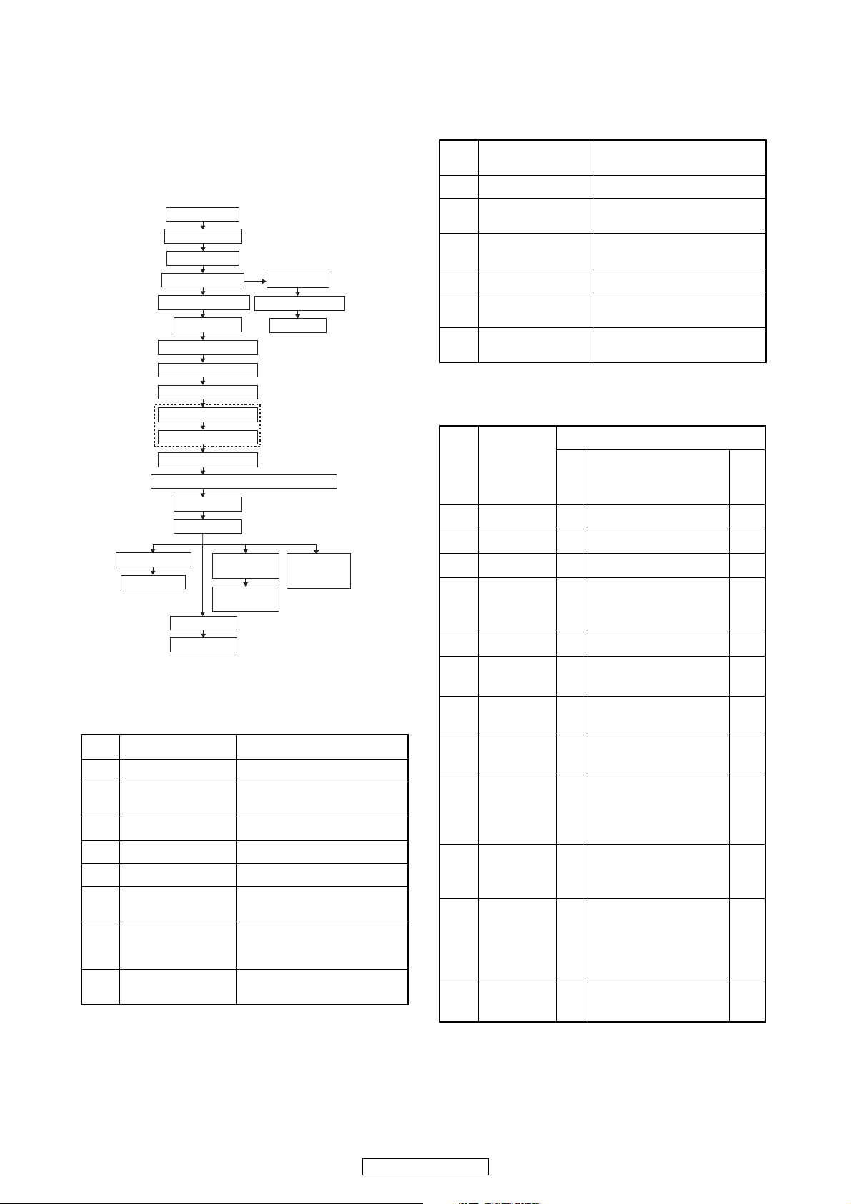
CABINET DISASSEMBLY INSTRUCTIONS
1. Disassembly Flowchart
This flowchart indicates the disassembly steps to gain
access to item(s) to be serviced. When reassembling,
follow the steps in reverse order. Bend, route, and
dress the cables as they were originally.
[1] Top Cover
[2] Top Panel
[3] Tray Panel
[4] Front Assembly
[8] Front Bracket
[9] Rear Panel
[10] BE Main CBA Unit
[11] Scaler CBA Unit
[12] D-Audio CBA
[13] F-Audio CBA
[14] S-Audio CBA
[15] ADSP CBA Unit
[16] FE Main CBA & BD Mechanism Assembly
[17] Fan Holder
[18] Fan Motor
[19] RS232C CBA
[20] Jack CBA
[23] AV CBA
[25] Pedestal
[21] Power
Supply CBA
[22] Sub Power
[5] Front CBA
[6] Power Switch CBA
[7] SD CBA
Analog Audio CBA Unit
CBA
[24] Sub
Microcontroller
CBA
[18] Fan Motor
[19] RS232C CBA [1]→[2]→ [9]→[10]→[11]→[19]
[20] Jack CBA
[21] Power Supply CBA
[22] Sub Power CBA [1] → [2] → [3] → [4] → [8] → [22]
[23] AV CBA
Sub Microcontroller
[24]
CBA
[1] → [2] → *[9](S-14) → [10] →
[11] → [17] → [18]
[1]→[2]→ [9]→[10]→[11]→[19]
→ [20]
[1] → [2] → *[9](S-14) → [10] →
[11] → [17] → [21]
[1]→ [2]→ [3]→ [9]→ [10]→ [11]
→ [12] → [13] → [14] → [23]
[1] → [2] → [12] → [13] → [14] →
[24]
*About *[9](S-14), remove only (S-14) of Rear Panel.
3. Disassembly Method
ID/
Loc.
No.
Part
Fig.
No.
[1] Top Cover D1 9(S-1), 2(S-2) --[2] Top Panel D2 10(S-3) --[3] Tray Panel D3 *2(L-1) 1
2(S-4), 2(S-5), (S-5a),
D3
*3(L-2), *CN2001,
*CN4002
[4]
Front
Assembly
[5] Front CBA D4 7(S-6) ---
Removal
Remove/*Unhook/
Unlock/Release/
Unplug/Desolder
Note
1
2. Disassembly of Main parts
When replacing the main parts, see the following procedures. For more details, refer to Fig. D1~D10.
Part Steps
[10] BE Main CBA Unit [1] → [2] → *[9](S-14) → [10]
[11] Scaler CBA Unit
[12] D-Audio CBA Unit [1] → [2] → [9] → [12]
[13] F-Audio CBA Unit [1] → [2] → [9] → [12] → [13]
[14] S-Audio CBA Unit [1]→[2]→[9]→ [12]→[13]→[14]
[15] ADSP CBA Unit
FE Main CBA & BD
[16]
Mechanism
Assembly
[17] Fan Holder
[1]→[2]→ [3]→ *[9](S-14)→[10]
→ [11]
[1]→[2]→[9]→[10]→[11]→ [12]
→ [13] → [14] → [15]
[1]→[2]→ [3]→ *[9](S-14)→[10]
→ [16]
[1] → [2] → *[9](S-14) → [10] →
[11] → [17]
Power
[6]
Switch CBA
[7] SD CBA D4
Front
[8]
Bracket
[9] Rear Panel D5
BE Main
[10]
CBA Unit
Scaler CBA
[11]
Unit
D-Audio
[12]
CBA
D4 2(S-7), Desolder ---
2(S-8), SD PCB
Holder
---
D5 2(S-9) ---
2(S-10), 2(S-11),
2(S-12), 18(S-13),
4(S-14), 3(S-15),
2(S-16) *CN1001
4(S-17), *CN6401,
D6
*CN7001, *CN7401,
*CX813
4(S-18), 3(S-19),
3(S-20), *CX874,
D6
*CX875, *CY080,
--BE Scaler Holder, BE
Scaler Sub Holder
D7 2(S-21), *CX877 ---
2
2
13
DVD-3800BDCI
ID/
Loc.
No.
[13]
[14]
[15]
[16]
[17] Fan Holder D8 2(S-29), *CN2500 --[18] Fan Motor D8 2(S-30) ---
[19]
Part
F-Audio
CBA
S-Audio
CBA
ADSP CBA
Unit
FE Main
CBA & BD
Mechanism
Assembly
RS232C
CBA
Fig.
No.
3(S-22), *CN061,
D7
*CN10, *CX201,
*CY281
D7 3(S-23) ---
2(S-24), (S-25),
4(S-26), 2(S-27),
D7
*CX876, DSP PCB
Holder, Audio PCB
Holder
D8 4(S-28), *CN2601 ---
3(S-31), *CN2551,
D9
RS232C Holder
Removal
Remove/*Unhook/
Unlock/Release/
Unplug/Desolder
Note
---
---
---
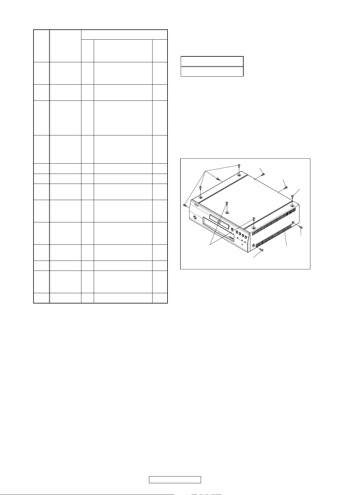
About tightening screws
When tightening screws, tighten them with the
following torque.
Torque
0.45 ± 0.05 N·m
Reference Notes
1. CAUTION 1: Locking Tabs (L-1) and (L-2) are
fragile. Be careful not to break them.
1) Release three Locking Tabs (L-2).
2) Disconnect connectors CN2001, CN4002, then
remove the Front Assembly.
2. CAUTION 2: When installing the BE Main CBA
Unit with a screw, hold and press the BE Main
CBA Unit to align the HDMI connector with the
connector’s hole for HDMI on the Rear Panel.
(S-1)
(S-2)
(S-2)
(S-1)
(S-32), (S-33),
[20] Jack CBA D9
Power
[21]
Supply
CBA
Sub Power
[22]
CBA
[23] AV CBA D9 7(S-38), *CN2503 ---
Sub
[24]
Microcontro
ller CBA
[25] Pedestal D10 3(S-40) ---
↓
(1)
Note:
(1) Identification (location) No. of parts in the figures
(2) Name of the part
(3) Figure Number for reference
(4) Identification of parts to be removed, unhooked,
unlocked, released, unplugged, unclamped, or
desoldered.
P = Spring, L = Locking Tab, S = Screw,
CN = Connector
* = Unhook, Unlock, Release, Unplug, or Desolder
e.g. 2(S-2) = two Screws (S-2),
2(L-2) = two Locking Tabs (L-2)
(5) Refer to “Reference Notes.”
↓
(2)
*CN2730, BNC PCB
Holder
2(S-34), 2(S-35),
D9
*CN101, *CN2501
3(S-36), 2(S-37),
D9
Power PCB Holder
D10 4(S-39) ---
↓
(3)
↓
(4)
---
---
---
(5)
(S-1)
(S-1)
(S-1)
[1] Top Cover
Fig. D1
↓
14
DVD-3800BDCI
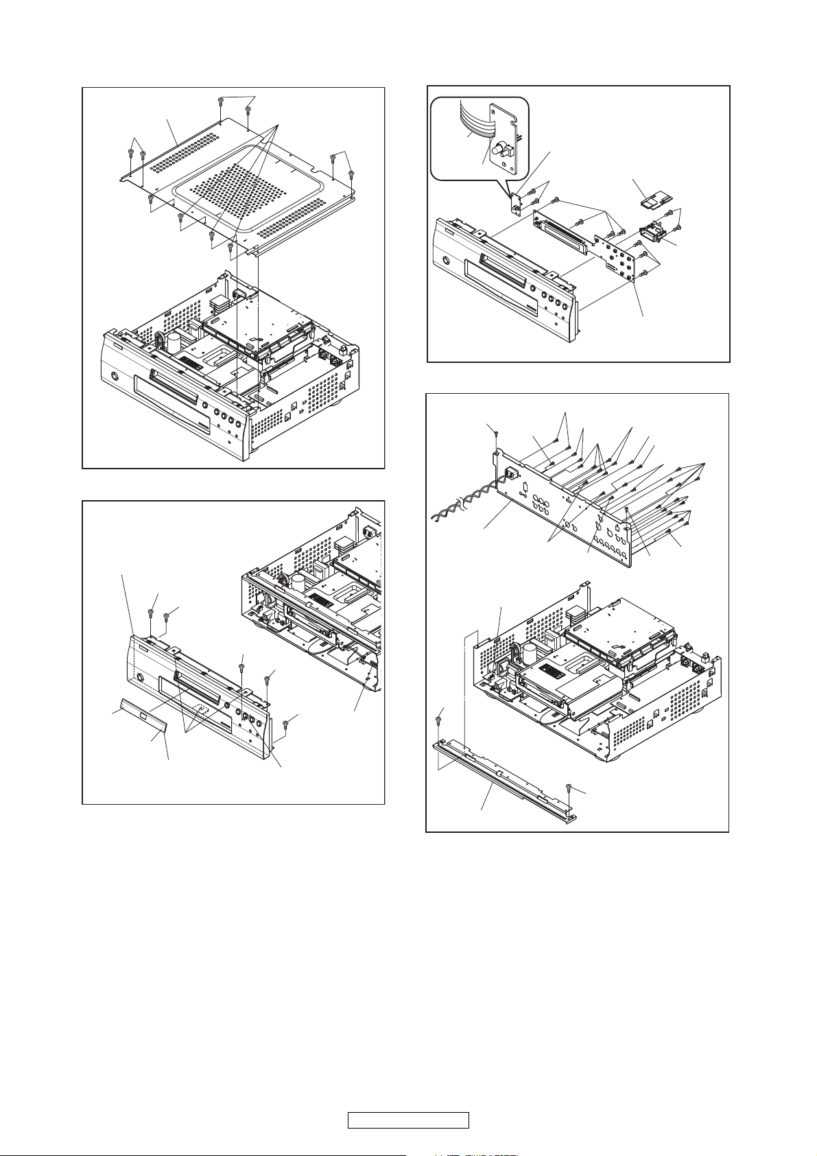
[2] Top Panel
(S-3)
(S-3)
(S-3)
(S-3)
Lead with
blue stripe
Desolder
[6] Power Switch CBA
[7] SD CBA
(S-7)
[4] Front Assembly
(S-4)
(S-5)
Fig. D2
(S-10)
[9] Rear Panel
CN1001
(S-15)
(S-16)
(S-12)
(S-11)
(S-15)
(S-6)
[5] Front CBA
(S-14)
(S-13)
*(S-14)
(S-14)
(S-13)
(S-10)
(S-8)
SD PCB
Holder
(S-6)
Fig. D4
(S-13)
(S-13)
(S-13)
(S-15)
(L-1)
(L-1)
(L-2)
[3] Tray Panel
(S-5a)
(S-4)
(S-5)
CN4002
CN2001
Fig. D3
(S-9)
[8] Front Bracket
(S-9)
Fig. D5
15
DVD-3800BDCI
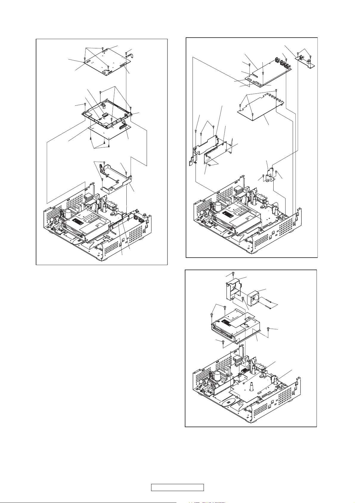
[10] BE Main
CBA Unit
CN6401
CN817
(S-18)
[11] Scaler
CBA Unit
(S-17)
CY080
(S-19)
(S-20)
CN7401
(S-18)
(S-19)
(S-17)
CN7001
CX813
BE Scaler
Holder
[13] F-Audio CBA
CY281
CX201
CN061
DSP PCB Holder
(S-25)
(S-24)
CX877
(S-26)
(S-26)
[12] D-Audio CBA
(S-22)
(S-23)
[14] S-Audio CBA
[15] ADSP CBA
Unit
Audio PCB Holder
(S-22)
(S-22)
CN10
(S-21)
CX875
CX874
BE Scaler
Sub Holder
Fig. D6
CX876
(S-28)
(S-28)
(S-29)
(S-27)
(S-27)
Fig. D7
[17] Fan Holder
[18] Fan Motor
(S-30)
(S-29)
(S-28)
[16] FE Main CBA &
BD Mechanism Assembly
CN2500
CN2601
16
DVD-3800BDCI
Fig. D8
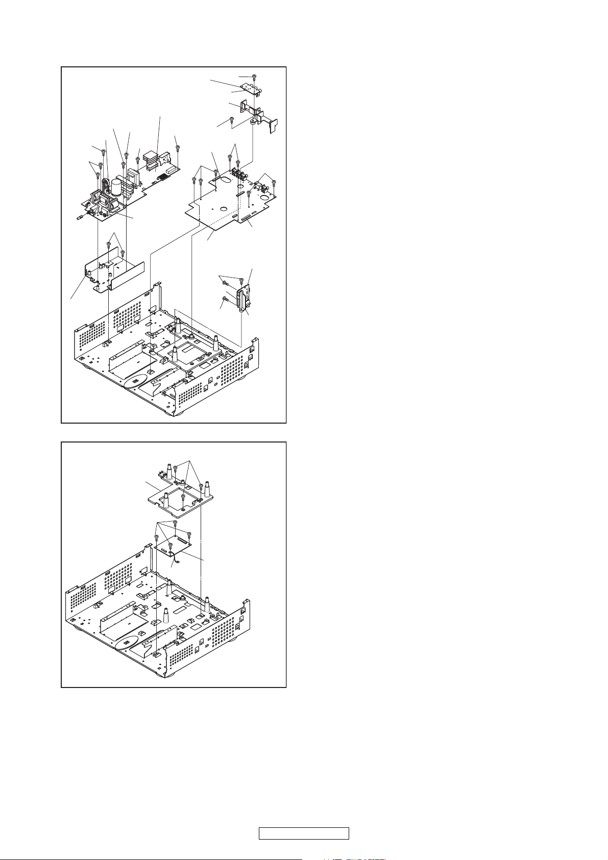
[21] Power Supply CBA
(S-36)
CN101
(S-35)
(S-36)
(S-37)
Power PCB
Holder
[20] Jack CBA
(S-35)
(S-34)
[22] Sub
Power CBA
(S-32)
BNC PCB Holder
(S-34)
CN2730
(S-33)
CN2501
(S-38)
[23] AV CBA
[19] RS232C CBA
(S-31)
CN2551
(S-31)
(S-38)
(S-38)
CN2503
RS232C
Holder
[25] Pedestal
(S-39)
Wire
Fig. D9
(S-40)
[24] Sub
Microcontroller
CBA
Fig. D10
17
DVD-3800BDCI
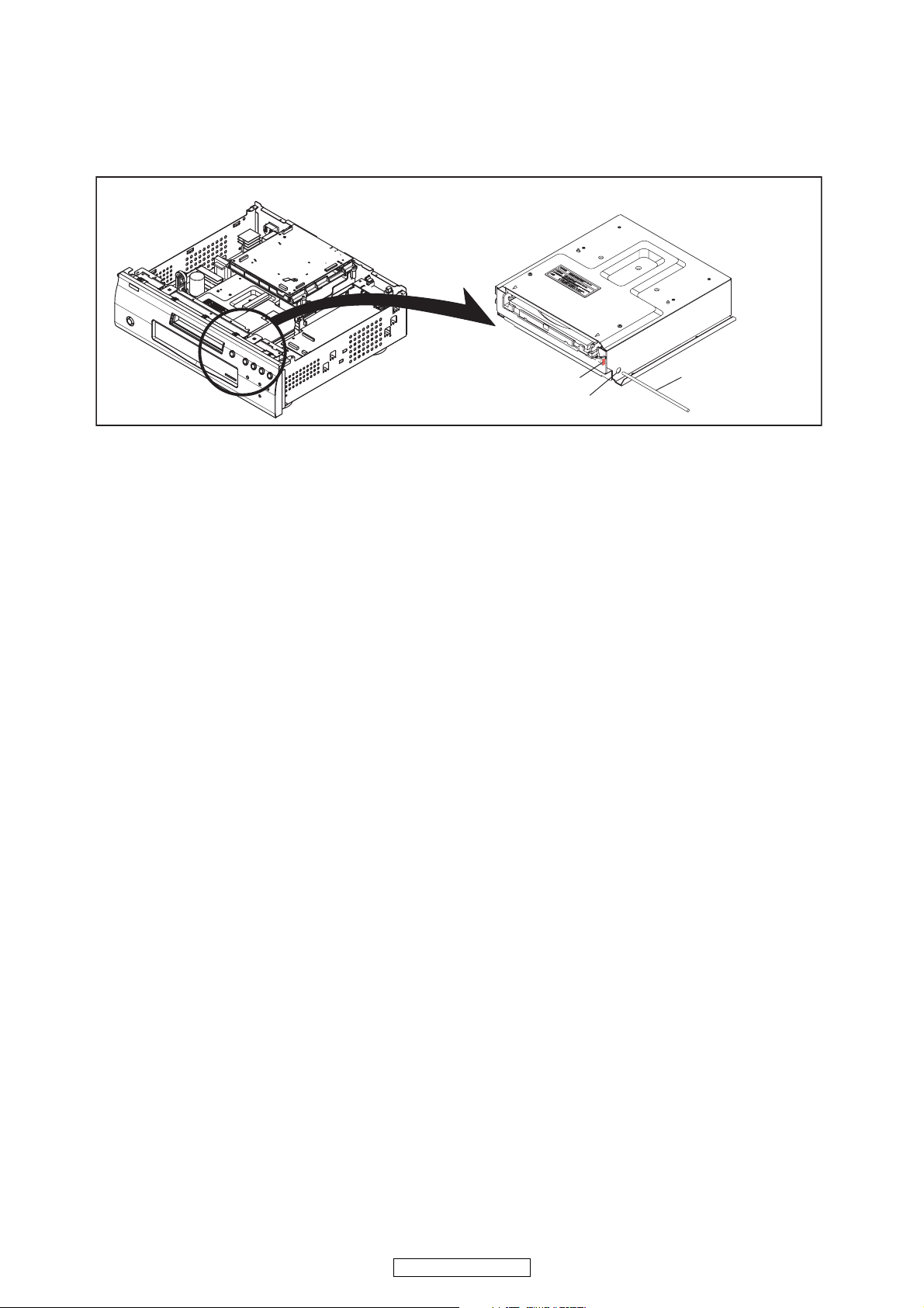
4. How to Eject Manually
1. Remove the Top Cover and the Top Panel.
2. Insert a screwdriver, etc. into the Hole A straightly so that the Portion A is pushed.
3. Pull the tray out manually and remove a disc.
Portion A
Hole A
Screwdriver,
hexagon wrench
18
DVD-3800BDCI

HOW TO INITIALIZE THE BLU-RAY DISC PLAYER
To put the program back at the factory-default,
initialize the BD player as the following procedure.
1. Turn the power on by pressing the [POWER]
button and the tray will close.
2. Press [1], [2], [3], [4], and [DISPLAY] buttons on
the remote control unit in that order.
Fig. a appears on the screen.
"
" differ depending on the models.
*******
MODEL : *******
Version
Region
3. Press [RED] button on the remote control unit.
Fig. b appears on the screen and Fig. c appears
on the VFD.
: *.***
: * / *
Fig. a
"
" differ depending on the models.
*******
EXIT: POWEREEPROM CLEAR : RED
MODEL : *******
Version
Region
EEPROM CLEAR : OK
: *.***
: * / *
EXIT: POWEREEPROM CLEAR : RED
Fig. b
Fig. c
4. To exit this mode, press [POWER OFF] button.
19
DVD-3800BDCI
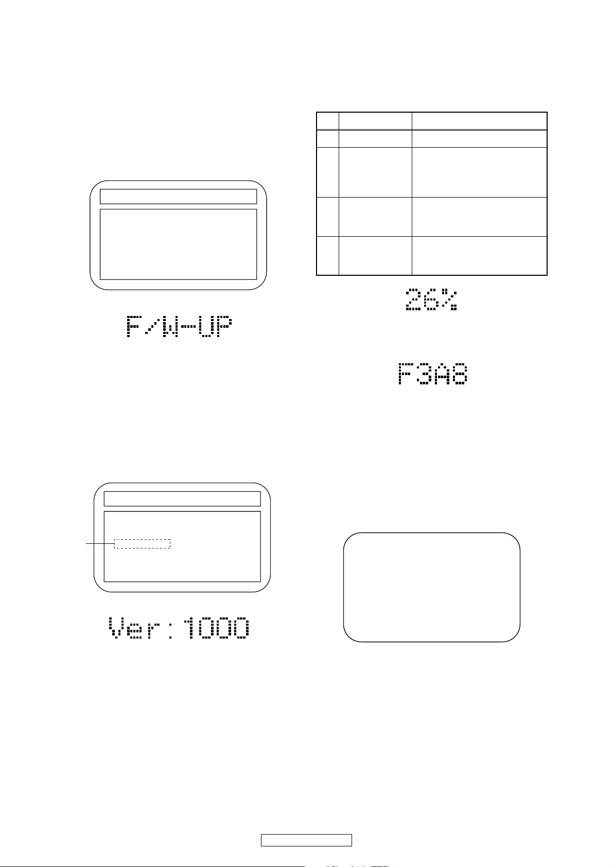
FIRMWARE RENEWAL MODE
1. Turn the power on and remove the disc on the tray.
2. To put the BD player into version up mode, press
[9], [8], [7], [6], and [MENU/POP MENU] buttons
on the remote control unit in that order. The tray
will open automatically.
Fig. a appears on the screen and Fig. b appears
on the VFD.
"
" differs depending on the models.
*******
F/W VERSION UP MODE Model No : ******* VERSION : *.***
Please insert a DISC
for F/W Version Up.
Fig. a Version Up Mode Screen
Fig. b VFD in Version Up Mode
The BD player can also enter the version up mode
with the tray open. In this case, Fig. a will be
shown on the screen while the tray is open.
3. Load the disc for version up.
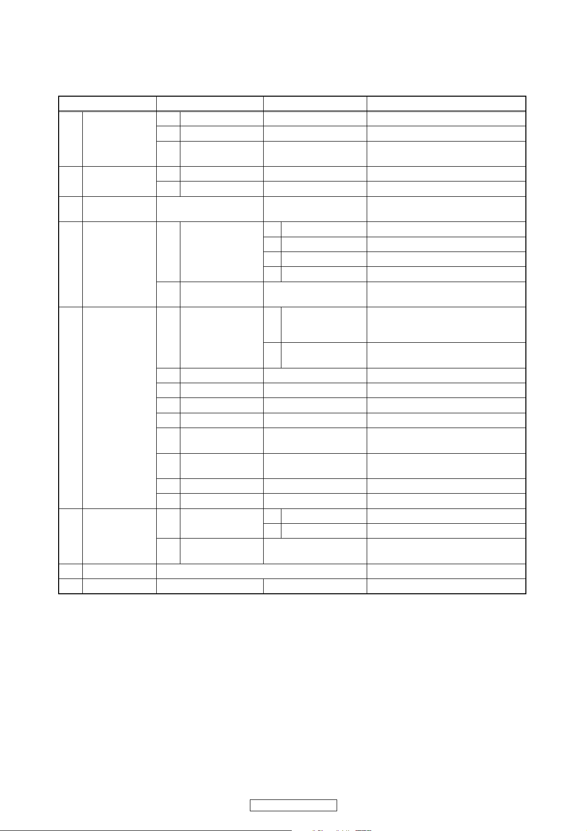
4. The BD player enters the F/W version up mode
automatically. Fig. c appears on the screen and
Fig. d appears on the VFD. If you enter the F/W for
different models, “Disc Error” will appear on the
screen, then the tray will open automatically.
"
" differs depending on the models.
*******
F/W VERSION UP MODE Model No : ******* VERSION : *.***
1. ALL
VERSION : *.** ************A*.bin
(*1)
Now Loading...
The appearance shown in (*1) of Fig. c is
described as follows:
No. Appearance State
1 Now Loading... Loading the disc
Sending files into the
2 Reading...
memory.
After reading, automatically
the tray opens.
Remove the
3
disc
Reading has finished.
Remove the disc and close
the tray.
Writing new version data,
4 See FL display
the progress will be displayed
as shown in Fig. e.
Fig. e VFD in Version Up Mode
5. After programming is finished, the checksum on
the VFD (Fig. f).
Fig. f VFD upon Finishing the Programming Mode (Example)
At this time, no button is available.
6. Unplug the AC cord from the AC outlet. Then plug
it again.
7. Turn the power on by pressing the [POWER ON]
button and the tray will close.
8. Press [1], [2], [3], [4], and [DISPLAY] buttons on
the remote control unit in that order.
Fig. g appears on the screen.
"
" differ depending on the models.
*******
MODEL : *******
Version
Region
: *.***
: * / *
Fig. c Programming Mode Screen (Example)
Fig. d VFD in Programming Mode (Example)
EXIT: POWEREEPROM CLEAR : RED
Fig. g
20
DVD-3800BDCI

9. Press [STOP] button on the remote control unit.
Fig. h appears on the screen and Fig. i appears on
the VFD.
"
" differ depending on the models.
*******
MODEL : *******
Version
Region
EEPROM CLEAR : OK
: *.***
: * / *
EXIT: POWEREEPROM CLEAR : RED
Fig. h
Fig. i
10. To exit this mode, press [POWER OFF] button.
21
DVD-3800BDCI
SERVICE MODE
Service Mode
1st level 2nd level 3rd level Description
1 Tray Aging Aging of tray open/close
1 Mecha test
2 VFD/LED Test
3Error Rate
4LD Test
5 Channel Level
6 RS-232C
7 SD Card Test
8 Default Setting Default setting
2 TOC Read TOC reading
3Heat Run
1 All On Turning on all VFD
2 All Off Turning off all VFD
1 Off Turning off LD
1LD Power
2 Operating Time
1TEST TONE
2 Front Lch
3Center
4Front Rch
5 Surround Rch
Surround Back
6
Rch
Surround Back
7
Lch
8 Surround Lch
9 Sub woofer
1 Parity Setting
2 Version Up Mode
2 BD Turning on BD LD
3 DVD Turning on DVD LD
4 CD Turning on CD LD
Center/
1
Subwoofer/Front
LR
Surround LR/
2
Surround Back LR
1 Even Setting even parity
2 Non Setting non parity
Tray close -> TT1 playback -> TT10
playback -> Tray open -> Tray close
Displaying Error rate, Jitter
during playback
Displaying LD Operation Time
(with clear function)
Realta Version up with connecting
RS-232C
Note: If some test are performed continuously, any error will occur.
22
DVD-3800BDCI
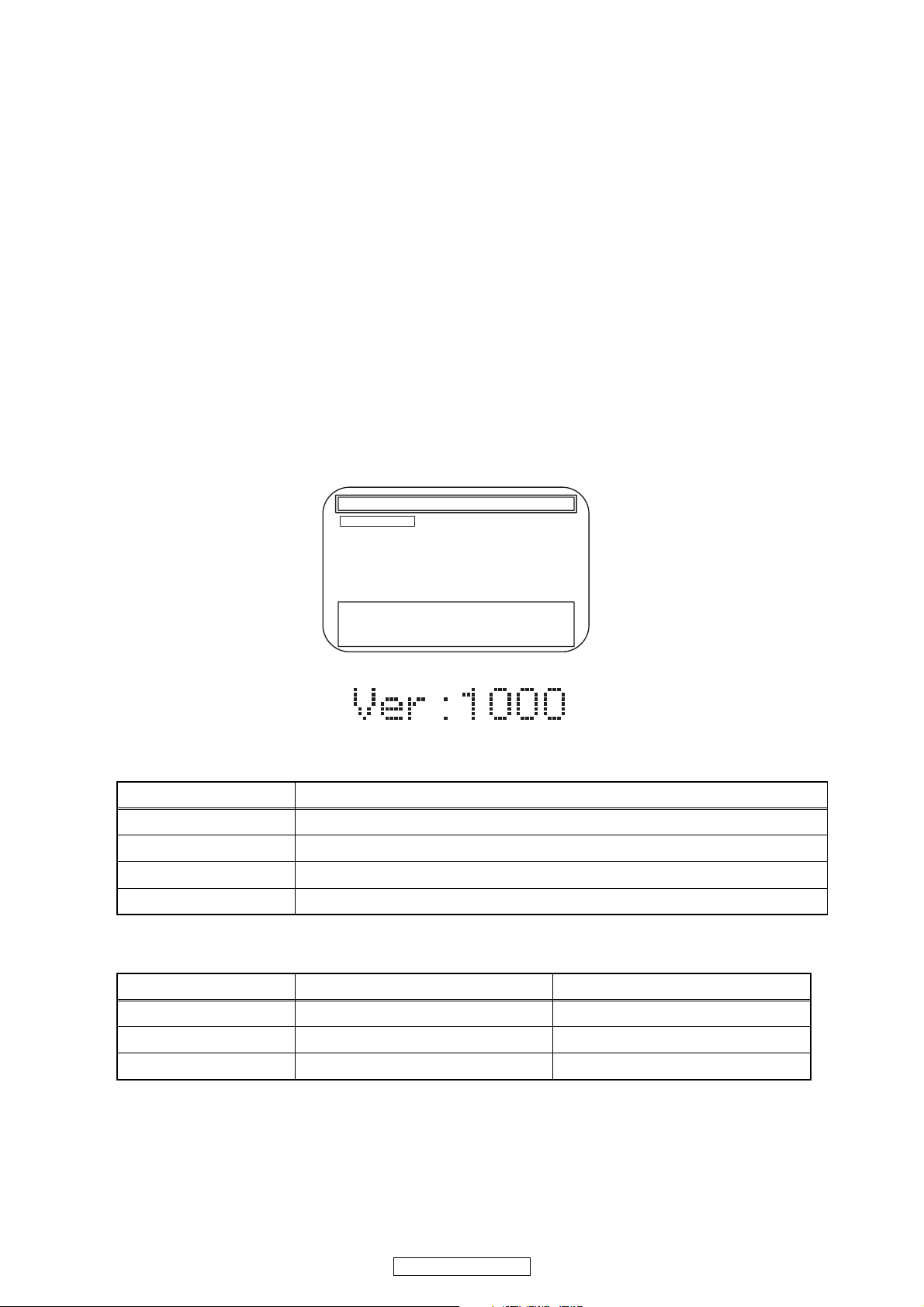
Entering Service Mode
In power on condition, no discs and tray close, it will be entered into service mode by the following operation using
the remote controller. However, it will not be entered when Media Select Item is SD Memory.
Service Mode by using remote controller
Press the following buttons on the remote controller in power on condition, no discs and tray close;
[2]->[5]->[8]->[0]->[CLEAR]
Release from Service Mode
Press the [POWER OFF] button to turn off power.
Screen saver/Auto Power Off in Service Mode
These functions are not performed in Service Mode.
After entering, Fig. j appears on the screen and Fig. k appears on the VFD.
* Firmware Version differs depending on the
models, and this indication is one example.
Service Mode
1. Mecha Test
2. VFD/LED Test
3: Error Rate
4: LD Test
5: RS-232C
6: Channel Level
7: SD Card Test
8: Default Setting
Model: :E5E**UD Region :A-1
Release Ver. :*.***
ADSP1/2 Ver.: ****/**** PLD Ver. :*
FPGA Ver.:** I/P Scaler Ver.:*****
Fig. j Service Mode (Main menu)
Fig. k Service Mode
Available button in service mode
Button condition
ENTER Enter the next level
POWER Turn the power off (when the service mode is completed)
1~8 Enter the selected item (next level)
OTHER Not available
Note:Press the number key to select items. Or, press the cursor button (up/down) to select items and press
[ENTER] button.
INDICATION DESCRIPTION REMARK
Model Name Model Name E5E***D, etc.
Region BD region - DVD region A-1, etc.
Rel. Ver. Release version
23
DVD-3800BDCI

TRAY LOCK MODE
Tray Lock Mode prevents the tray opening or closing to
prevent disc theft in demo mode.
Enter this mode using the following procedure.
1. Confirm that the TV Monitor is connected.
2. With playback stopped, press [SETUP], [TOP
MENU], [3], [AUDIO], [0] and [SETUP] buttons on
the remote control unit in that order. "Trade On" will
appear in the upper right corner on the screen, and
on VFD for 2 seconds.
Fig.a VFD
3. To exit this mode, press [SETUP], [TOP MENU],
[3], [AUDIO], [0] and [SETUP] buttons on the
remote control unit in that order. "Trade Off" will
appear in the upper right corner on the screen, and
on VFD for 2 seconds.
Fig.b VFD
24
DVD-3800BDCI
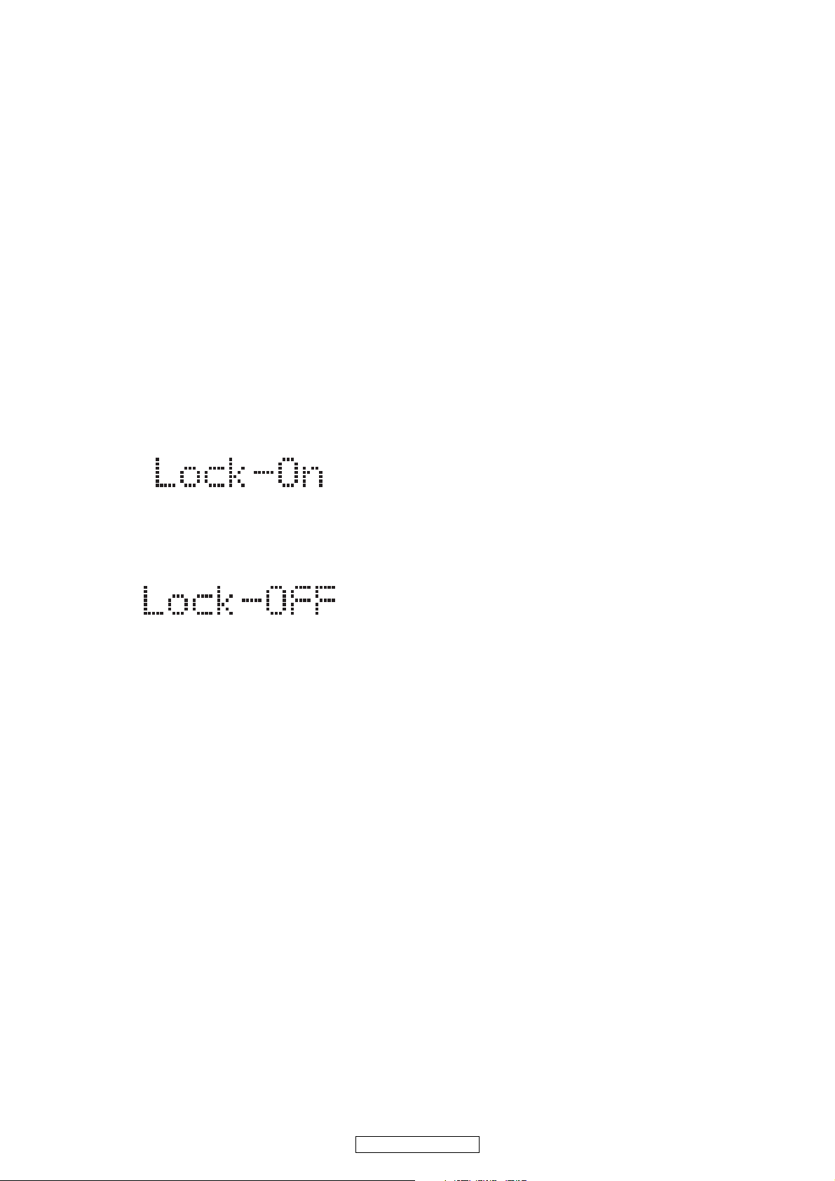
REMOTE LOCK MODE
SETTING MENU:
Remote Lock Off Mode:
This mode receives an input signal from the remote
control unit or from the Remote In-Jack on the rear
panel.
Remote Lock On Mode:
This mode dose not receive an input signal from
the remote control unit or from the Remote In-Jack
on the rear panel.
Perform the setting using the following procedure.
1. Press [ON/STANDBY] and [STOP] buttons on the
front panel simultaneously for over 3 seconds to set
"Remote Lock Mode" and display mode.
2. Press [STILL/PAUSE] button on the remote control
unit to set to "On" or "Off". When "Remote Lock
On", "Remote Lock On" will appear in the upper
right corner on the screen and appears on the VFD.
Fig.a VFD
When "Remote Lock Off", "Remote Lock Off" will
appear in the upper right corner on the screen and
appears on the VFD.
Fig.b VFD
a. If [STILL/PAUSE] button is not pressed for 5
seconds or any other button is pressed within 5
seconds, the unit will be released from
"Remote Lock Mode".
b. When initializing, set the Remote Lock Mode
"off".
25
DVD-3800BDCI
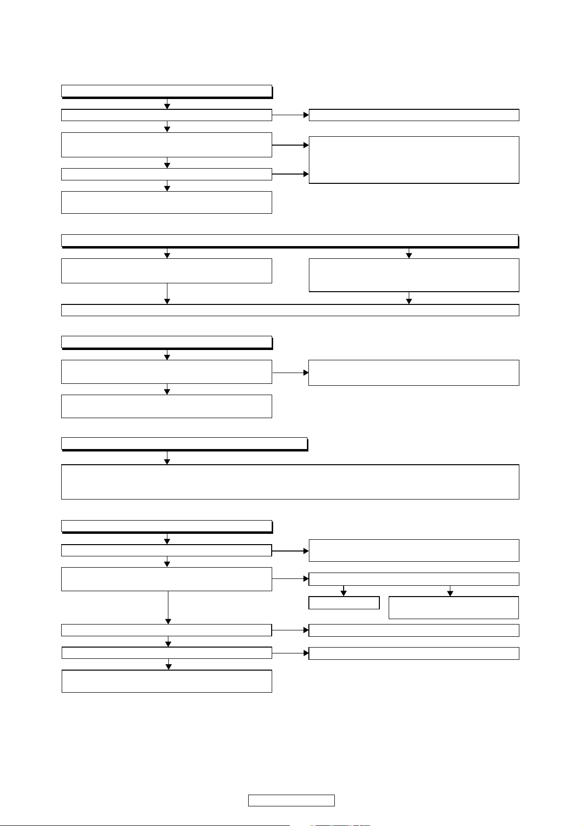
FLOW CHART NO.1
The power cannot be turned on.
TROUBLESHOOTING
Is the fuse normal?
Ye s
Is normal state restored when once unplugged
power cord is plugged again after several seconds?
Ye s
Is the AL+5V line voltage normal?
Ye s
Check each rectifying circuit of the secondary circuit
and service it if defective.
FLOW CHART NO.2
The fuse blows out.
Check the presence that the primary component
is leaking or shorted and service it if defective.
After servicing, replace the fuse.
FLOW CHART NO.3
When the output voltage fluctuates.
Does the photo coupler circuit on the secondary
side operate normally?
Ye s
Check D1107, IC1101, IC1103 and their periphery,
and service it if defective.
No
No
No
No
See FLOW CHART No.2 <The fuse blows out.>
Check if there is any leak or short-circuiting on the
primary circuit component, and service it if defective.
(D1101, D1102, D1103, D1104, D1109, D1110,
IC1101, Q1103, T1101, C1110, R1117)
Check the presence that the rectifying diode or
circuit is shorted in each rectifying circuit of
secondary side, and service it if defective.
Check D1117, D1129, IC1103 and their periphery,
and service it if defective.
FLOW CHART NO.4
When buzz sound can be heard in the vicinity of power circuit.
Check if there is any short-circuit on the rectifying diode and the circuit in each rectifying circuit of the secondary
side
, and service it if defective.
IC1105, IC1106, IC2600, IC2601, Q2600, Q2606, Q2608, Q2610, Q2611)
FLOW CHART NO.5
-FL is not outputted.
Is -30V voltage supplied to the emitter of Q2503?
Is the "L" signal outputted to the collector of
Q2507?
Is 3.3V voltage supplied to the emitter of Q2504?
Is 3.3V voltage outputted to collector of Q2504?
Check Q2503 and their periphery, and service it if
defective.
(D1112, D1113, D1114, D1115, D1116, D1118, D1120, D1121,D1122, D1124, D1146,
Check D1118, D1130, C1126 and periphery circuit,
and service it if defective.
Is the "H" signal inputted to the base of Q2507?
Ye s
Replace Q2507.
Check EV+3.3V line and service it if defective.
Replace Q2504.
Check FL-SW line and service
it if defective.
No
Ye s
Ye s
Ye s
Ye s
No
No
No
No
26
DVD-3800BDCI
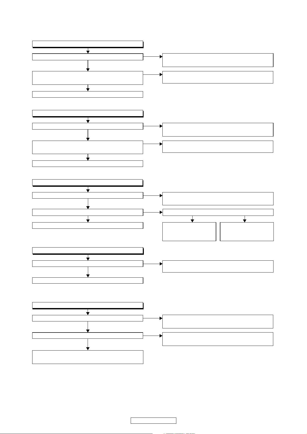
FLOW CHART NO.6
P-ON+5V (1) is not outputted.
Is 5V voltage inputted to the emitter of Q2610?
Ye s
Is the voltage of base on Q2610 lower than the
voltage of emitter on Q2610 when turning the power on?
Ye s
Replace Q2610.
FLOW CHART NO.7
P-ON+5V (2) is not outputted.
Is 5V voltage inputted to the emitter of Q2606?
Ye s
Is the voltage of base on Q2606 lower than the
voltage of emitter on Q2606 when turning the power on?
Ye s
Replace Q2606.
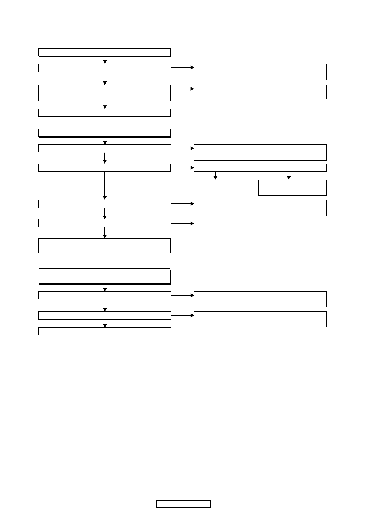
FLOW CHART NO.8
P-ON+10.5V is not outputted.
Is 13.5V voltage inputted to the collector of Q2611?
Ye s
Is 11V voltage inputted to the base of Q2611? Is 13.5V voltage inputted to the base of Q2605?
Ye s Ye s No
Replace Q2611.
FLOW CHART NO.9
P-ON+1.2V is not outputted.
No
No
No
No
No
No
Check D1112, D1113, D1114, D1129, C1125, C1132
and their periphery, and service it if defective.
Check Q2607 and PWSW3 line and service it if
defective.
Check D1112, D1113, D1114, D1129, C1125, C1132
and their periphery, and service it if defective.
Check Q2607 and PWSW3 line and service it if
defective.
Check D1122, D1128, C1124, L1105
their periphery, and service it if defective.
Check Q2605, D2601,
and their periphery, and
service it if defective.
Check Q2604,
PWSW3 line, and
service it if defective.
and
and
Is 2.5V voltage supplied to Pin(1) of IC2601?
Ye s
Replace IC2601.
FLOW CHART NO.10
P-ON+3.3V is not outputted.
Is 5V voltage supplied to Pin(1) of IC2600?
Ye s
ls "L" signal outputted to the collector of Q2603?
Ye s
Check IC2600, D2600 and their periphery circuit,
and service it if defective.
No
No
No
Check D1115, C1119
and service it if defective.
Check D1112, D1113, D1114, D1129, C1125, C1132 and
their periphery circuit, and service it if defective.
Check Q2603 and PWSW3 line and service it if
defective.
and their periphery circuit,
27
DVD-3800BDCI
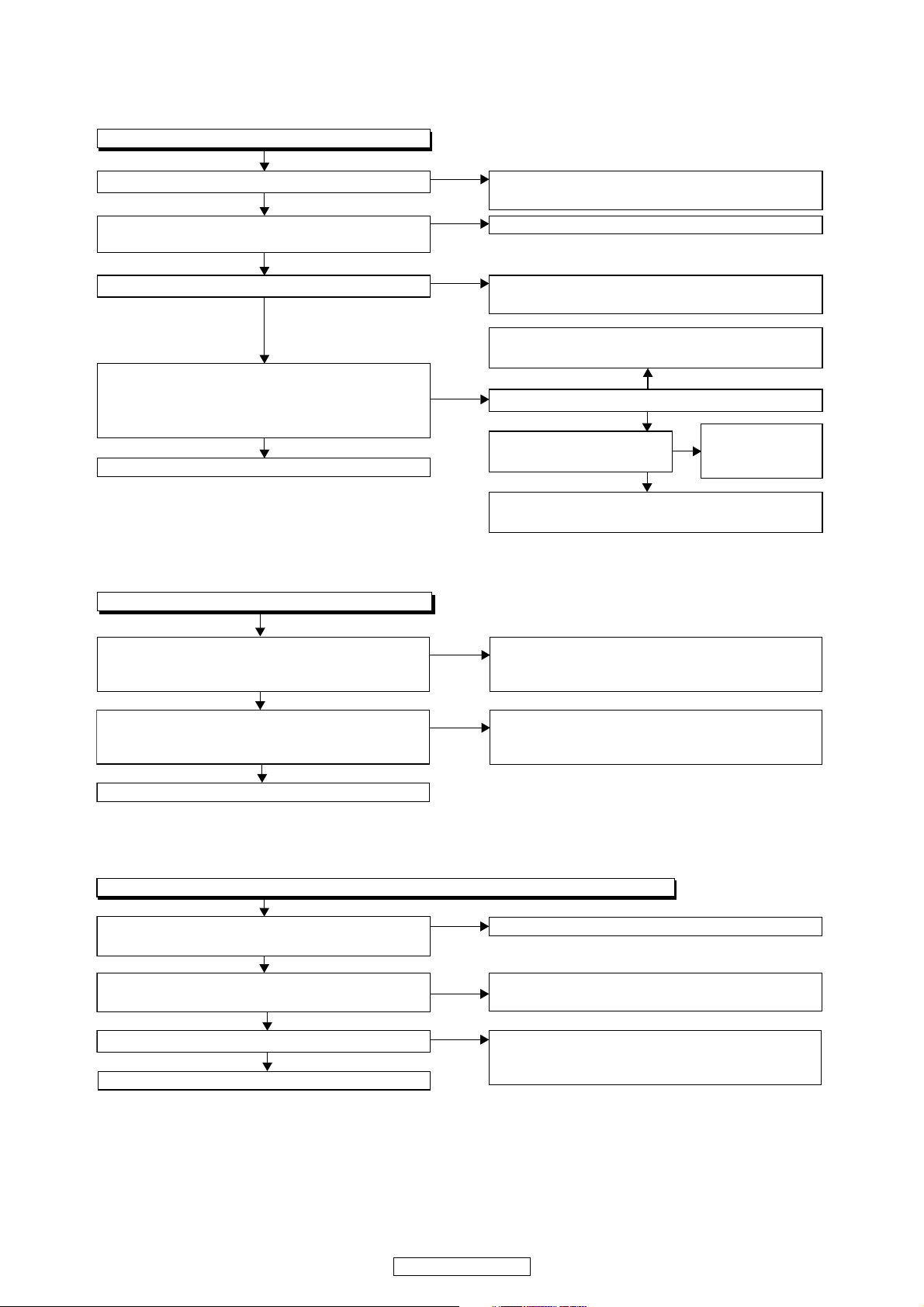
FLOW CHART NO.11
P-ON+15V is not outputted.
Is 14V voltage inputted to the emitter of Q2609?
Ye s
Is the voltage of base on Q2609 lower than the
voltage of emitter on Q2609 when turning the power on?
Ye s
Replace Q2609.
FLOW CHART NO.12
P-ON-12V is not outputted.
Is -12V voltage inputted to the emitter of Q2600?
Ye s
ls "L" signal outputted to the collector of Q2601? ls "H" signal inputted to the base of Q2601?
Ye s
Is 5V voltage inputted to the emitter of Q2602?
Ye s
Is 5V voltage outputted to the collector of Q2602?
Ye s
Check Q2600
it if defective.
and their periphery, and service
No
No
No
No
No
No
Check D1121, D1127, C1123, L1104 and their
periphery, and service it if defective.
Check Q2604 and PWSW3 line and service it if
defective.
Check D1124, D1125, C1121, L1102
and their periphery, and service it if defective.
Ye s
Replace Q2601.
Check D1112, D1113, D1114, D1129, C1132, C1125
and their periphery, and service it if defective.
Replace Q2602.
Check PWSW3 line and
service it if defective.
No
FLOW CHART NO.13
EV+3.3V(2) is not outputted.
(AL+5V is output normally.)
Is 3.3V voltage inputted to the emitter of Q2613?
Ye s
Is 2.6V voltage inputted to the base of Q2613?
Ye s
Replace Q2613.
No
No
Check D1145, R1128, R1129, R1130
their periphery, and service it if defective.
Check Q2612
and service it if defective.
and A33-PW-CONT line,
and
28
DVD-3800BDCI
FLOW CHART NO.14
The fluorescent display tube does not light up.
Is 3.3V voltage supplied to Pin(64) of IC3001?
Ye s
Is the voltage of approximately -30V supplied to
Pin(56) of IC3001?
Ye s
Is there 1.8MHz oscillation at Pin(58) of IC3001?
Ye s
Are the filament voltage supplied between Pin(1)
and Pin(62) of the fluorescent display tube?
And the negative voltage applied between these
pins and GND?
Ye s
Replace the fluorescent display tube.
FLOW CHART NO.15
The key operation is not functioning.
No
No
No
No
Check the P-ON+3.3V line and service it if
defective.
Check the -FL line and service it if defective.
Check R3006, C3003, IC3001 and their periphery,
and service it if defective.
Check D1116, D1123, C1117 and their periphery,
and service it if defective.
No
Is -20V voltage supplied to collector of Q2502?
Ye s
Is the "H" signal inputted
to the base of Q2507?
Ye s
Check Q2502, Q2508 and their periphery,
and service it if defective.
Check FL-SW
line, and service
No
it if defective.
Are the contact point and the installation state of
the key switches (SW3000-3004,
SW3006-SW3010, SW3100) normal?
Ye s
When pressing each switches (SW3000-3004,
SW3006-SW3010, SW3100), do the voltage of
Pin(3,4) of IC2000 increase?
Ye s
Replace IC2000.
FLOW CHART NO.16
No operation is possible from the remote control unit.(Operation is possible from the unit.)
Is 5V voltage supplied to Pin(1) of RS3000
(remote control receiver) ?
Ye s
Is the "L" pulse sent out Pin(1) of RS3000 (remote
control receiver) when the remote control unit is activated?
Ye s
Is the "H" pulse inputted to the Pin(27) of IC2000?
Ye s
Replace IC2000.
No
No
No
No
No
Re-install the switches (SW3000-3004,
SW3006-SW3010, SW3100) correctly or replace
the poor switch.
Check the switches (SW3000-3004,
SW3006-SW3010,SW3100) and their periphery,
and service it if detective.
Check EV+5V line and service it if defective.
Replace the RS3000 (remote control receiver) or
remote control unit.
Check the line between the
receiver)
detective.
and the
Pin(27) of IC2000,
RS3000 (remote control
and service it if
29
DVD-3800BDCI