

Page 1

AV SURROUND RECEIVER
AVR-5805CI
OPERATING INSTRUCTIONS
Page 2
2 SAFETY PRECAUTIONS
CAUTION
RISK OF ELECTRIC SHOCK
DO NOT OPEN
CAUTION: TO REDUCE THE RISK OF ELECTRIC SHOCK,
DO NOT REMOVE COVER (OR BACK). NO
USER-SERVICEABLE PARTS INSIDE. REFER
SERVICING TO QUALIFIED SERVICE
PERSONNEL.
The lightning flash with arrowhead symbol, within an
equilateral triangle, is intended to alert the user to the
presence of uninsulated “dangerous voltage” within the
product’s enclosure that may be of sufficient magnitude to
constitute a risk of electric shock to persons.
The exclamation point within an equilateral triangle is intended
to alert the user to the presence of important operating and
maintenance (servicing) instructions in the literature
accompanying the appliance.
WARNING: TO REDUCE THE RISK OF FIRE OR ELECTRIC
SHOCK, DO NOT EXPOSE THIS APPLIANCE
TO RAIN OR MOISTURE.
FCC INFORMATION (For US customers)
1. COMPLIANCE INFORMATION
Product Name: AV Surround Receiver
Model Number: AVR-5805CI
This product complies with Part 15 of the FCC Rules. Operation is subject to
the following two conditions: (1) this product may not cause harmful
interference, and (2) this product must accept any interference received,
including interference that may cause undesired operation.
Denon Electronics (USA), LLC
(a D & M Holdings Company)
100 Corporate Drive
Mahwah, NJ 07430-2041
Tel. (800) 497-8921
2. IMPORTANT NOTICE: DO NOT MODIFY THIS PRODUCT
This product, when installed as indicated in the instructions contained in this
manual, meets FCC requirements. Modification not expressly approved by
DENON may void your authority, granted by the FCC, to use the product.
3. NOTE
This product has been tested and found to comply with the limits for a Class
B digital device, pursuant to Part 15 of the FCC Rules. These limits are
designed to provide reasonable protection against harmful interference in a
residential installation.
This product generates, uses and can radiate radio frequency energy and, if
not installed and used in accordance with the instructions, may cause
harmful interference to radio communications. However, there is no
guarantee that interference will not occur in a particular installation. If this
product does cause harmful interference to radio or television reception,
which can be determined by turning the product OFF and ON, the user is
encouraged to try to correct the interference by one or more of the following
measures:
• Reorient or relocate the receiving antenna.
• Increase the separation between the equipment and receiver.
• Connect the product into an outlet on a circuit different from that to which
the receiver is connected.
• Consult the local retailer authorized to distribute this type of product or an
experienced radio/TV technician for help.
This Class B digital apparatus complies with Canadian ICES-003.
Cet appareil numérique de la classe B est conforme à la norme NMB-003 du
Canada.
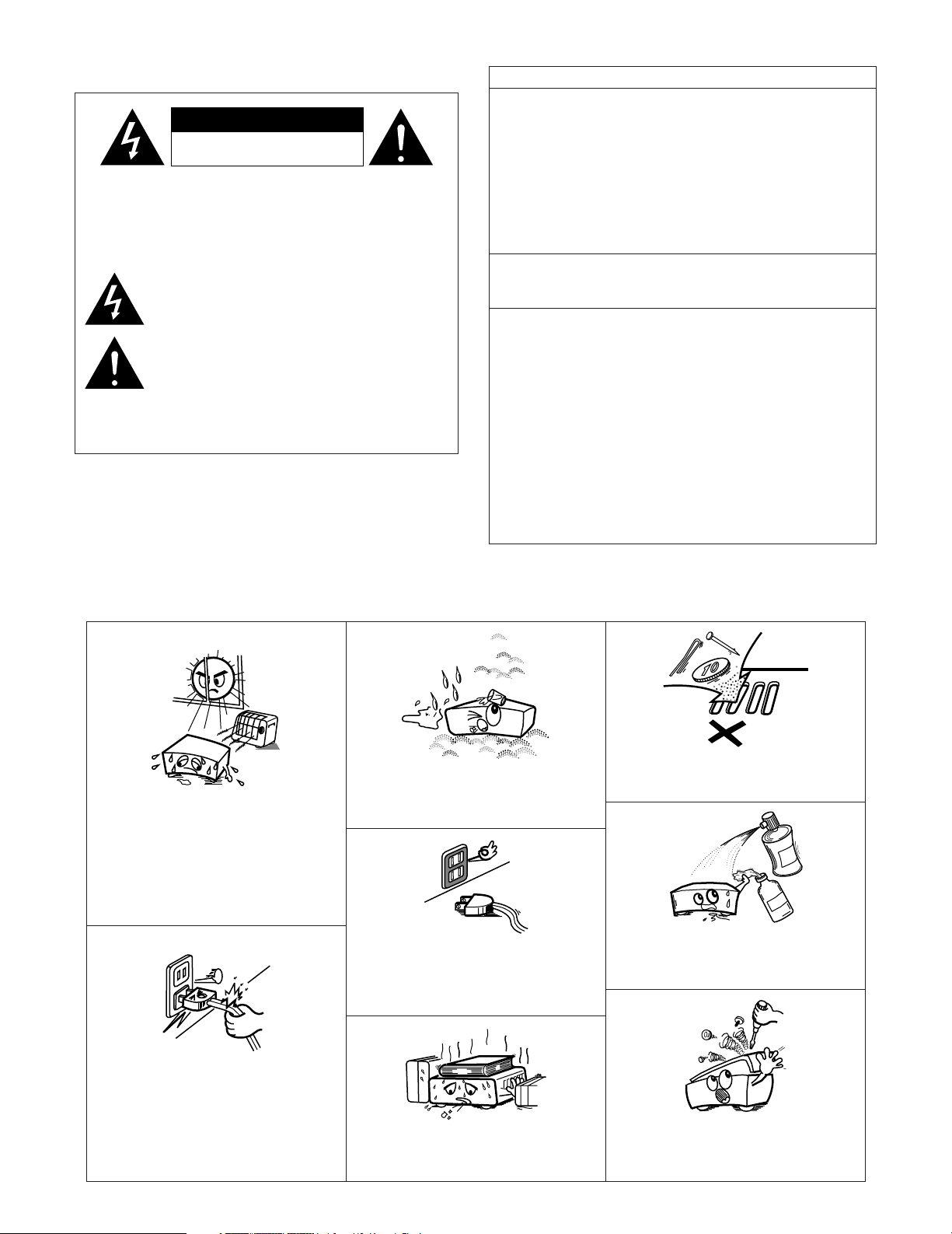
2 NOTE ON USE / OBSERVATIONS RELATIVES A L’UTILISATION
•Avoid high temperatures.
Allow for sufficient heat dispersion when
installed in a rack.
• Eviter des températures élevées
Tenir compte d’une dispersion de chaleur
suffisante lors de l’installation sur une
étagère.
• Handle the power cord carefully.
Hold the plug when unplugging the cord.
• Manipuler le cordon d’alimentation avec
précaution.
Tenir la prise lors du débranchement du
cordon.
• Keep the apparatus free from moisture,
water, and dust.
•Protéger l’appareil contre l’humidité, l’eau et
lapoussière.
• Unplug the power cord when not using the
apparatus for long periods of time.
•Débrancher le cordon d’alimentation lorsque
l’appareil n’est pas utilisé pendant de
longues périodes.
* (For apparatuses with ventilation holes)
• Do not obstruct the ventilation holes.
• Ne pas obstruer les trous d’aération.
2
• Do not let foreign objects into the apparatus.
• Ne pas laisser des objets étrangers dans l’appareil.
• Do not let insecticides, benzene, and thinner come
in contact with the apparatus.
•Ne pas mettre en contact des insecticides, du
benzène et un diluant avec l’appareil.
• Never disassemble or modify the apparatus
in any way.
• Ne jamais démonter ou modifier l’appareil
d’une manière ou d’une autre.
Page 3
SAFETY INSTRUCTIONS
1. Read Instructions – All the safety and operating instructions
should be read before the product is operated.
2. Retain Instructions – The safety and operating instructions
should be retained for future reference.
3. Heed Warnings – All warnings on the product and in the
operating instructions should be adhered to.
4. Follow Instructions – All operating and use instructions should
be followed.
5. Cleaning – Unplug this product from the wall outlet before
cleaning. Do not use liquid cleaners or aerosol cleaners.
6. Attachments – Do not use attachments not recommended by
the product manufacturer as they may cause hazards.
7. Water and Moisture – Do not use this product near water – for
example, near a bath tub, wash bowl, kitchen sink, or laundry
tub; in a wet basement; or near a swimming pool; and the like.
8. Accessories – Do not place this product on an unstable cart,
stand, tripod, bracket, or table. The product may fall, causing
serious injury to a child or adult, and serious damage to the
product. Use only with a cart, stand, tripod, bracket, or table
recommended by the manufacturer, or sold with the product.
Any mounting of the product should follow the manufacturer’s
instructions, and should use a
mounting accessory
recommended by the
manufacturer.
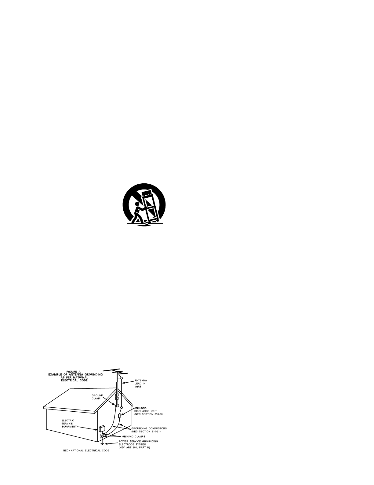
9. A product and cart
combination should be
moved with care. Quick
stops, excessive force,
and uneven surfaces may
cause the product and cart
combination to overturn.
10. Ventilation – Slots and openings in the cabinet are provided for
ventilation and to ensure reliable operation of the product and to
protect it from overheating, and these openings must not be
blocked or covered. The openings should never be blocked by
placing the product on a bed, sofa, rug, or other similar surface.
This product should not be placed in a built-in installation such
as a bookcase or rack unless proper ventilation is provided or
the manufacturer’s instructions have been adhered to.
11. Power Sources – This product should be operated only from the
type of power source indicated on the marking label. If you are
not sure of the type of power supply to your home, consult your
product dealer or local power company. For products intended
to operate from battery power, or other sources, refer to the
operating instructions.
12. Grounding or Polarization – This product may be equipped with
a polarized alternating-current line plug (a plug having one blade
wider than the other). This plug will fit into the power outlet
only one way. This is a safety feature. If you are unable to
insert the plug fully into the outlet, try reversing the plug. If the
plug should still fail to fit, contact your electrician to replace your
obsolete outlet. Do not defeat the safety purpose of the
polarized plug.
13. Power-Cord Protection – Power-supply cords should be routed
so that they are not likely to be walked on or pinched by items
placed upon or against them, paying particular attention to
cords at plugs, convenience receptacles, and the point where
they exit from the product.
15. Outdoor Antenna Grounding – If an outside antenna or cable
system is connected to the product, be sure the antenna or
cable system is grounded so as to provide some protection
against voltage surges and built-up static charges. Article 810
of the National Electrical Code, ANSI/NFPA 70, provides
information with regard to proper grounding of the mast and
supporting structure, grounding of the lead-in wire to an
antenna discharge unit, size of grounding conductors, location
of antenna-discharge unit, connection to grounding electrodes,
and requirements for the grounding electrode. See Figure A.
16. Lightning – For added protection for this product during a
lightning storm, or when it is left unattended and unused for
long periods of time, unplug it from the wall outlet and
disconnect the antenna or cable system. This will prevent
damage to the product due to lightning and power-line surges.
17. Power Lines – An outside antenna system should not be
located in the vicinity of overhead power lines or other electric
light or power circuits, or where it can fall into such power lines
or circuits. When installing an outside antenna system,
extreme care should be taken to keep from touching such
power lines or circuits as contact with them might be fatal.
18. Overloading – Do not overload wall outlets, extension cords, or
integral convenience receptacles as this can result in a risk of
fire or electric shock.
19. Object and Liquid Entry – Never push objects of any kind into
this product through openings as they may touch dangerous
voltage points or short-out parts that could result in a fire or
electric shock. Never spill liquid of any kind on the product.
Servicing – Do not attempt to service this product yourself as
20.
opening or removing covers may expose you to dangerous
voltage or other hazards. Refer all servicing to qualified
service personnel.
21.
Damage Requiring Service – Unplug this product from the
wall outlet and refer servicing to qualified service
under the following conditions:
a) When the power-supply cord or plug is damaged,
b) If liquid has been spilled, or objects have fallen into the
product,
c) If the product has been exposed to rain or water,
d) If the product does not operate normally by following the
operating instructions. Adjust only those controls that are
covered by the operating instructions as an improper
adjustment of other controls may result in damage and will
often require extensive work by a qualified technician to
restore the product to its normal operation,
e) If the product has been dropped or damaged in any way, and
f) When the product exhibits a distinct change in performance
– this indicates a need for service.
22. Replacement Parts – When replacement parts are required, be
sure the service technician has used replacement parts
specified by the manufacturer or have the same characteristics
as the original part. Unauthorized substitutions may result in
fire, electric shock, or other hazards.
23. Safety Check – Upon completion of any service or repairs to this
product, ask the service technician to perform safety checks to
determine that the product is in proper operating condition.
24. Wall or Ceiling Mounting – The product should be mounted to a
wall or ceiling only as recommended by the manufacturer.
25. Heat – The product should be situated away from heat sources
such as radiators, heat registers, stoves, or other products
(including amplifiers) that produce heat.
personnel
3
Page 4

Getting Started
Thank you for choosing the DENON AVR-5805CI AV Surround Receiver. This remarkable component has been engineered to
provide superb surround sound listening with home theater sources such as DVD, as well as providing outstanding high fidelity
reproduction of your favorite music sources.
As this product is provided with an immense array of features, we recommend that before you begin hookup and operation that
you review the contents of this manual before proceeding.
Contents
Getting Started
Accessories ...................................................................................7
Before using..................................................................................7
Cautions on installation............................................................7
Cautions on handling.................................................................8
Preparing the remote control unit.........................................8
Inserting the batteries...............................................................8
Operating range of the remote control unit.......................9
Part names and functions
Front panel .............................................................................10, 11
Display..........................................................................................12
Remote control unit .....................................................................13
Easy Setup and Operation
Easy to setup flow....................................................................14
Speaker system layout............................................................15
Speaker connections .........................................................16, 17
Connecting a DVD player and TV (Monitor)...............18, 19
Auto Setup / Room EQ ...........................................................20
Connecting a microphone ............................................................21
Turning on the power...................................................................22
Starting Auto Setup......................................................................22
Extra Setup...................................................................................23
Preliminary measurements ....................................................23, 24
Speaker system measurement ....................................................24
Check of the measurement result ...............................................25
About the error message .............................................................26
Connecting Other Sources
Cable indications
The video conversion function
On screen display for component video outputs and
HDMI output
Connecting equipment with HDMI terminals
[To convert analog video signals to HDMI signals]
Connecting a TV tuner
Connecting a DBS tuner
Connecting the external inputs (EXT. IN) terminals
Connecting a video camera or video game
Connecting a DVD recorder
Connecting a VCR
Connecting a CD player
Connecting a turntable
Connecting a CD recorder or MD recorder
Connecting a tape deck
DENON LINK connection
Connecting equipment with HDMI terminals
Connecting equipment with DVI-D terminals
Connecting IEEE1394 devices
Connecting the antenna terminals
Connecting the XM terminal
Connecting the CONTROL terminal
Connecting the TRIGGER OUT terminals
Connecting the MULTI ZONE terminals
ZONE2 connections .....................................................................41
Connecting the pre-out terminals
Connecting the power supply cord
..........................................................................27
....................................................28
..................................................................................28
...................29
.................................................................30
..............................................................30
.................31
...............................31
.........................................................32
.........................................................................33
...............................................................33
................................................................34
................................34
...............................................................35
.............................................................35
............................36
...........................37
......................................................38
.............................................39
.......................................................40
............................................40
...................................41
...............................................42
............................................42
Basic Operation
Playback
Operating the remote control unit ...............................................43
Playing the input source...............................................................44
Turning the sound off temporarily (MUTING)...............................45
Listening over headphones ..........................................................45
Switching the surround speakers ................................................45
Switching between HDMI and DVI-D monitor output .................45
Selection of resolution setting (SCALE) .......................................45
Combining the currently playing sound with the desired
image (VIDEO SELECT)................................................................45
Video on/off..................................................................................45
Checking the currently playing program source, etc. ..................46
Input mode ..........................................................................46 ~ 48
Room EQ function........................................................................48
Surround
Playing modes for different sources ............................................49
Playing audio sources (CDs and DVDs)
2 channel playback modes...........................................................50
THX Surround EX / Home THX Cinema mode
• Playing sources recorded in Dolby Surround in
the Home THX Cinema Surround mode ..................................51
•To play in the THX Surround EX / Home THX Cinema
Surround mode for sources recorded in Dolby Digital
or DTS .......................................................................................51 ~ 53
Dolby Digital mode and DTS Surround
(only with digital input) ...........................................................54, 55
Night mode ..................................................................................55
Dolby Pro Logic IIx (Pro Logic II) mode.................................56, 57
DTS NEO:6 mode.........................................................................58
The Dolby Headphone..................................................................59
USER MODE function..................................................................59
DENON original surround modes
Surround modes and their features .............................................60
DSP surround simulation .......................................................61, 62
Tone control setting
• Adjusting the tone from the remote control unit...............62, 63
• Adjusting the tone from the main unit.....................................63
•Tone defeat mode ....................................................................63
Channel Level...............................................................................64
Fader function ..............................................................................65
Listening to the radio
Auto tuning...................................................................................65
Manual tuning ..............................................................................66
Preset memory ............................................................................66
Checking the preset stations .......................................................67
Recalling preset stations ..............................................................67
RDS (Radio Data System) ............................................................67
RDS search ..................................................................................68
PTY search ...................................................................................69
TP search ...............................................................................69, 70
RT (Radio Text) .............................................................................70
XM Satellite Radio
Checking the XM signal strength and Radio ID ...........................71
Channel selection.........................................................................72
Category search ...........................................................................72
Direct access of channels ............................................................73
4
(to be continued on page 6.)
Page 5
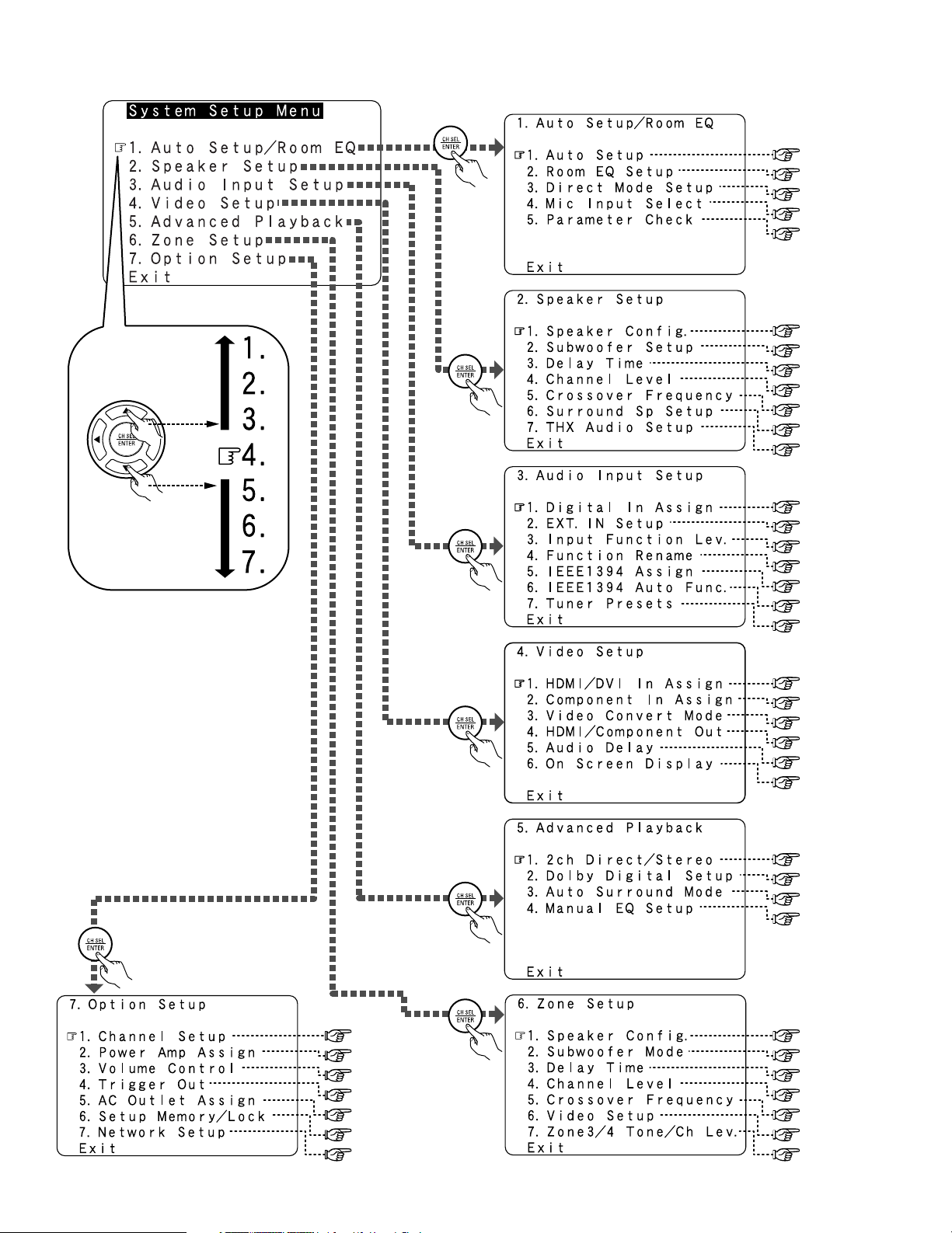
2 System Setup Menu
page 20 ~ 26
page 149
page 150
page 150, 151
page 151, 152
page 140, 141
page 141, 142
page 142, 143
page 143 ~ 145
page 145, 146
page 146, 147
page 147, 148
page 104
page 105
page 106
page 106, 107
page 107
page 108
page 108 ~ 110
page 126 ~ 128
page 129 ~ 133
page 134
page 135
page 136
page 137
page 138, 139
page 111, 112
page 112
page 112
page 113, 114
page 114
page 115
page 116
page 117
page 117
page 118, 119
page 120
page 120
page 121
page 122, 123
page 123
page 123,124
page 124, 125
5
Page 6

Getting Started
Using the Network Audio Function
Internet radio function..................................................................74
Music server function ..................................................................74
System requirements ..........................................................74 ~ 76
Listening to Internet radio......................................................76, 77
Presetting (registering) Internet radio stations.............................77
Registering Internet radio stations in your favorites..............77, 78
Character search function (searching by first letter) ....................78
Updating the list of radio stations ................................................79
Playing music files stored on the computer
(music server).........................................................................79, 80
Operating the AVR-5805CI using a browser................................80
Advanced Operation
Remote control unit
Operating DENON audio components.........................................81
Setting the preset memory function............................................82
Operating a component stored in the preset memory ..........82, 83
Setting the learning function........................................................84
Using the system call function.....................................................84
• Registering ...............................................................................85
• Operating..................................................................................85
Setting the punch through function .............................................85
Setting the back light’s lighting time............................................85
Setting the brightness..................................................................85
Resetting the remote control unit................................................86
Multi zone music entertainment system...........................87
ZONE2 playback ..................................................................87 ~ 90
ZONE3 playback...........................................................................91
ZONE4 playback...........................................................................92
Outputting a program source to an amplifier, etc.,
in a ZONE2 room (ZONE2 SELECT mode) ..................................93
Outputting a program source to an amplifier, etc.,
in a ZONE3 or ZONE4 room (ZONE3, ZONE4 SELECT mode) ....93
Remote control unit operations during multi-source playback.....94
System setup for multi-zone........................................................95
Adjustment steps that need to be performed prior to
surround sound playback in ZONE2
•Test Tone ..................................................................................95
• Channel Level...........................................................................95
• Fader function ..........................................................................96
ZONE2 Surround ..........................................................................97
USER MODE function of ZONE2 ................................................97
ZONE2 tone control setting .........................................................98
Other function
Playing Super Audio CDs with an IEEE1394 cable ......................99
Multi-source recording / playback
• Playing one source while recording another
(REC OUT mode)....................................................................100
• Recording Dolby Digital and DTS multi channel sources.......100
• Dolby Headphone recording...................................................101
Last function memory ................................................................101
Initialization of the microprocessor ............................................101
Advanced Setup – Part 1
Navigating through the System Setup Menu................102
On screen display and front display .................................103
Audio Input Setup
Setting the Digital In Assignment ..............................................104
• Setting the DENON LINK.......................................................104
Setting the EXT. IN Setup ..........................................................105
Setting the Input Function Level................................................106
Setting the Function Rename ............................................106, 107
Setting the IEEE1394 Assignment.............................................107
Setting the IEEE1394 Auto Function .........................................108
Tuner Presets
•Auto Preset Memory..............................................................108
•Preset Skip .............................................................................109
•Preset Name ..................................................................109, 110
Video Setup
Setting the HDMI/DVI In Assignment................................111, 112
Setting the Component In Assignment .....................................112
Setting the Video Convert Mode ...............................................112
Setting the HDMI/Component Out Setup .........................113, 114
Setting the Audio Delay .............................................................114
Setting the On Screen Display (OSD) ........................................115
Advanced Playback
Setting the 2ch Direct/Stereo ....................................................116
Setting the Dolby Digital Setup..................................................117
Setting the Auto Surround Mode...............................................117
Setting the Manual EQ Setup ............................................118, 119
•Procedure for copying the “Flat” correction curve ................119
Zone Setup (ZONE2 = 5.1/7.1ch)
Setting the type of speakers for ZONE2....................................120
Setting the low frequency distribution for ZONE2.....................120
Setting the Delay Time for ZONE2.............................................121
Setting the Channel Level for ZONE2................................122, 123
Setting the Crossover Frequency for ZONE2 ............................123
Setting the Video Setup for ZONE2
•Video Convert Mode (ZONE2) ................................................123
• Audio Delay (ZONE2)..............................................................124
Setting the ZONE3 and ZONE4 tone control
and channel level .................................................................124, 125
Option Setup
Setting the Channel Setup ..............................................126 ~ 128
Setting the Power Amplifier Assignment........................129 ~ 133
Setting the Volume Control........................................................134
Setting the Trigger Out...............................................................135
Setting the AC Outlet Assignment ............................................136
Memory backup and protecting the setting ..............................137
Setting the Network Setup ................................................138, 139
Advanced Setup – Part 2
Speaker Setup
Setting the type of speakers..............................................140, 141
Setting the low frequency distribution...............................141, 142
Setting the Delay Time.......................................................142, 143
Setting the Channel Level ...............................................143 ~ 145
• Adjusting the test tone using the remote control unit...........145
Setting the Crossover Frequency ......................................145, 146
• Setting the crossover frequency individually for the
different channels...................................................................146
Selecting the Surround Speakers
for the different surround modes ......................................146, 147
Settings the THX Audio Setup
• Settings for using a THX Ultra2 compatible subwoofer ........147
• Surround Back Speaker Position Settings..............................148
Others Setup
Setting the Room EQ Setup ......................................................149
Setting the Direct Mode Setup ..................................................150
Setting the MIC Input Select .............................................150, 151
Check the parameter .........................................................151, 152
System setup items and default values................153 ~ 156
Troubleshooting ..............................................................157, 158
Additional information ...............................................159 ~ 173
Specifications...................................................................174, 175
List of preset code
s ········································End of this manual
6
Page 7
r
t
yui
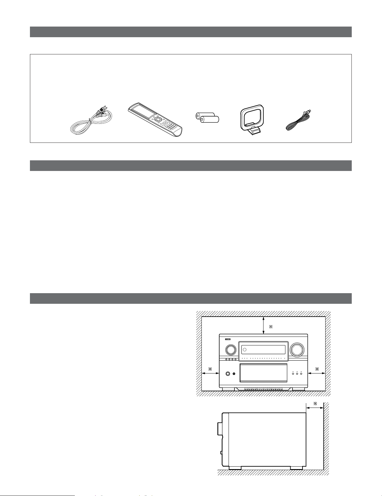
Accessories
• Check that the following parts are included in addition to the main unit:
Getting Started
q Operating instructions ..................................................1
w Warranty (for North America model only).....................1
e Service station list.........................................................1
r Power supply cord ........................................................1
Before using
Pay attention to the following before using this unit:
• Moving the set
To prevent short circuits or damaged wires in the connection
cables, always unplug the power supply cord and disconnect
the connection cables between all other audio components
when moving the set.
• Before turning the Power operation button on
Check once again that all connections are proper and that
there are not problems with the connection cables. Always
set the power operation button to the standby position
before connecting and disconnecting connection cables.
t Remote control unit (RC-1036) .....................................1
y LR6/AA alkaline batteries..............................................2
u AM loop antenna ..........................................................1
i FM indoor antenna........................................................1
• Store these instructions in a safe place.
After reading, store these instructions along with the
warranty in a safe place.
• Note that the illustrations in these instructions may
differ from the actual set for explanation purposes.
Cautions on installation
Noise or disturbance of the picture may be generated if this
unit or any other electronic equipment using microprocessors
is used near a tuner or TV.
If this happens, take the following steps:
• Install this unit as far as possible from the tuner or TV.
• Set the antenna wires from the tuner or TV away from this
unit’s power supply cord and input/output connection cables.
• Noise or disturbance tends to occur particularly when using
indoor antennas or 300 Ω/ohms feeder wires. We
recommend using outdoor antennas and 75 Ω/ohms
coaxial cables.
Note:
For heat dispersal, do not install this unit in a confined
space such as a bookcase or similar enclosure.
Note
Wall
7
Page 8
Getting Started
Cautions on handling
• Switching the input function when input terminals are
not connected.
A clicking noise may be produced if the input function is
switched when nothing is connected to the input terminals.
If this happens, either turn down the MASTER VOLUME
control knob or connect components to the input terminals.
• Muting of PRE OUT terminals and SPEAKER terminals.
The PRE OUT terminals and SPEAKER terminals include a
muting circuit. Because of this, the output signals are
greatly reduced for several seconds after the power switch
is turned on or input function, surround mode or any otherset-up is changed. If the volume is turned up during this
time, the output will be very high after the muting circuit
stops functioning. Always wait until the muting circuit turns
off before adjusting the volume.
• Whenever the power operation button is in the
STANDBY state, the apparatus is still connected on AC
line voltage.
Please be sure to turn off the power switch or unplug
the cord when you leave home for, say, a vacation.
Preparing the remote control unit
• The included remote control unit (RC-1036) can be used to operate not only the AVR-5805CI but other remote control
compatible DENON components as well. In addition, the memory contains the control signals for other remote control units,
so it can be used to operate non-DENON remote control compatible products.
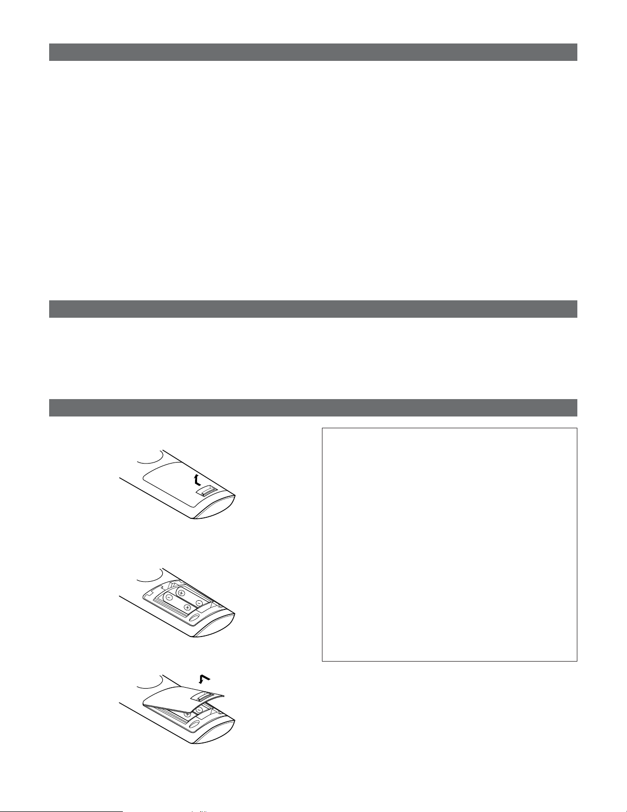
Inserting the batteries
q Remove the remote control unit’s rear cover.
w Set two LR6/AA batteries in the battery compartment in
the indicated direction.
e Put the rear cover back on.
Notes on batteries:
• Replace the batteries with new ones if the set does not
operate even when the remote control unit is operated
nearby the set. (The included battery is only for verifying
operation.)
• When inserting the batteries, be sure to do so in the
proper direction, following the “<” and “>” marks in the
battery compartment.
•To prevent damage or leakage of battery fluid:
•Do not use a new battery together with an old one.
• Do not use two different types of batteries.
• Do not short-circuit, disassemble, heat or dispose of
batteries in flames.
• Remove the batteries from the remote if it will not be in
use for long periods.
•If the battery fluid should leak, carefully wipe the fluid off
the inside of the battery compartment and insert new
batteries.
•When replacing the batteries, have the new batteries
ready and insert them as quickly as possible.
8
Page 9
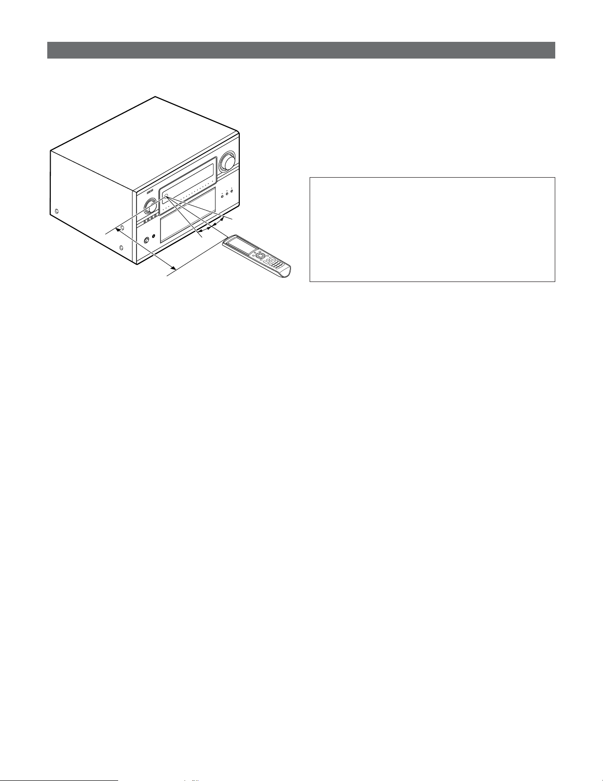
Operating range of the remote control unit
30°
30°
Approx. 23 feet/7 m
Getting Started
• Point the remote control unit at the remote sensor on the
main unit as shown on the diagram.
• The remote control unit can be used from a straight distance
of approximately 23 feet/7 meters from the main unit, but
this distance will be shorter if there are obstacles in the way
or if the remote control unit is not pointed directly at the
remote sensor.
• The remote control unit can be operated at a horizontal angle
of up to 30 degrees with respect to the remote sensor.
NOTE:
• It may be difficult to operate the remote control unit if the
remote sensor is exposed to direct sunlight or strong
artificial light.
• Do not press buttons on the main unit and remote control
unit simultaneously. Doing so may result in malfunction.
• Neon signs or other devices emitting pulse-type noise
nearby may result in malfunction, so keep the set as far
away from such devices as possible.
9
Page 10
Getting Started
!3 !2 !1 !0 o
q w e r t y
u i
!4 !5 !6 !7
!8
!9
@0
#7 #9 $1 $2#5
#4#2 #6 #8 $0
#3 $7$5$3 $9
%0
%1
$8$6$4
@2@1 @3 @4 @5 @8@7@6 @9 #0 #1
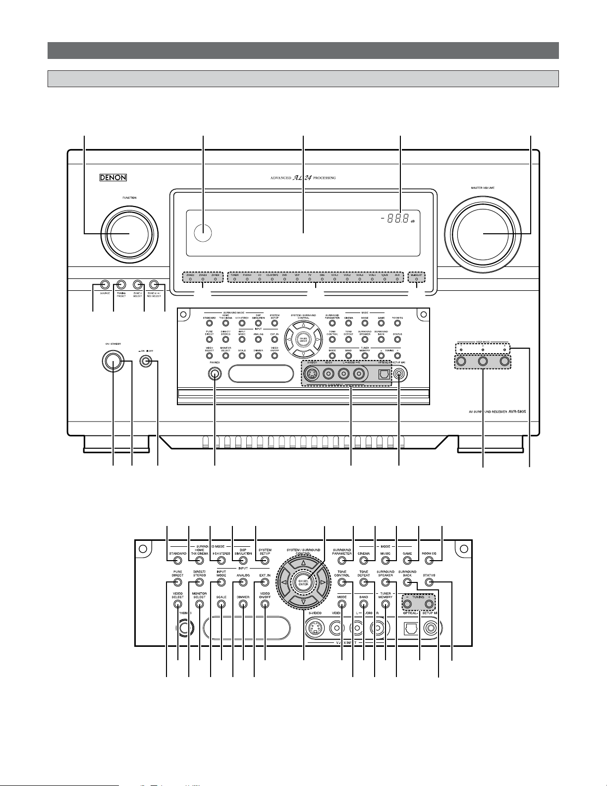
Part names and functions
Front panel
• For details on the functions of these parts, refer to the pages given in parentheses ( ).
10
Page 11

Getting Started
q Power ON/STANDBY button................................(22)
w Power indicator ........................................................(22)
e Power switch ....................................................(22, 101)
r Headphones jack (PHONES) .................................(45)
t V. AUX INPUT terminals .........................................(31)
y SETUP MIC jack ........................................................(21)
u USER MODE buttons ..............................................(60)
i USER MODE indicators ..........................................(60)
o MASTER VOLUME control knob .........................(44)
!0 Master volume indicator........................................(44)
!1 Display ........................................................................(12)
!2 Remote control sensor .............................................(9)
!3 FUNCTION knob .......................................................(44)
!4 SOURCE button........................................................(44)
!5 TUNING PRESET button ........................................(67)
!6 ZONE2 SELECT button ...........................................(93)
!7 ZONE3/4/REC SELECT button .....................(93, 100)
!8 Multi Zone power indicators ................................(94)
!9 Input source indicators ..........................................(44)
@0 MultEQ XT indicator ...............................................(48)
@1 STANDARD button ..................................................(54)
@2 HOME THX CINEMA button .................................(44)
@3 9CH STEREO button................................................(62)
@4 DSP SIMULATION button......................................(62)
@5 SYSTEM SETUP button .........................................(22)
@6 CH SELECT/ENTER button..............................(22, 64)
@7 SURROUND PARAMETER button .......................(50)
@8 CINEMA button ........................................................(56)
@9 MUSIC button ...........................................................(56)
#0 GAME button ............................................................(56)
#1 ROOM EQ button .....................................................(48)
#2 PURE DIRECT button ..............................................(50)
#3 VIDEO SELECT button ............................................(46)
#4 DIRECT/STEREO button.........................................(50)
#5 MONITOR SELECT button .....................................(45)
#6 INPUT MODE button...............................................(47)
#7 SCALE button ...........................................................(45)
#8 ANALOG button .......................................................(47)
#9 DIMMER button........................................................(46)
$0 EXT.IN button............................................................(47)
$1 VIDEO ON/OFF button ...........................................(46)
$2 CURSOR buttons .....................................................(22)
$3 MODE button ............................................................(65)
$4 TONE CONTROL button.........................................(63)
$5 BAND button .............................................................(65)
$6 TONE DEFEAT button.............................................(63)
$7 MEMORY button ......................................................(66)
$8 SURROUND SPEAKER button..............................(45)
$9 TUNING buttons ......................................................(65)
%0 SURROUND BACK button .....................................(52)
%1 STATUS button.........................................................(46)
11
Page 12
Getting Started
u yo!0!1!3!2!4!6!7!8 !5 i
e
r t
q
w
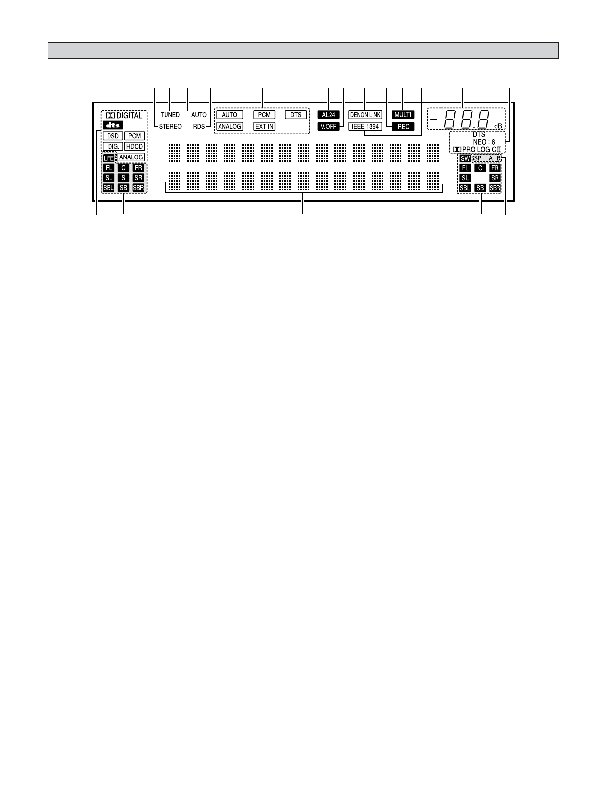
Display
q Input signal indicator
The respective indicator will light corresponding to the
input signal.
w Input signal channel indicator
The channels included in the input source will light.
This lights when the digital signal is input.
e Information display
This displays the surround mode, function name or setting
value, etc.
r Output signal channel indicator
The audio channels that can be output light.
t Speaker indicator
This lights corresponding to the settings of the surround
speakers of the various surround modes.
y Decoder indicator
This lights when each decoder is operating.
u Master volume indicator
This displays the volume level.
The Setup item number is displayed in System Setup.
i IEEE1394 indicator
This lights during playback in a IEEE1394 connection.
o MULTI (zone) indicator
ZONE3 mode is selected in ZONE3/REC SELECT.
!0 Recording output source indicator
REC OUT mode is selected in ZONE3/REC SELECT.
!1 DENON LINK indicator
This lights during playback in a DENON LINK connection.
!2 V. OFF indicator
This lights when the operation of the video circuit has been
turned off.
!3 AL24 indicator
The AL24 indicator lights when the PURE DIRECT, DIRECT,
STEREO, MULTI CH PURE DIRECT , MULTI CH DIRECT,
MULTI CH IN mode is selected in the PCM input signal.
!4 Input mode indicator
This lights corresponding to the setting of the INPUT mode.
!5 RDS indicator
This lights when RDS broadcast has been received.
!6 AUTO indicator
This lights when the broadcast station is selected in the
AUTO tuning mode.
!7 TUNED indicator
This lights when an FM/AM broadcast has been received.
!8 STEREO indicator
This lights when an FM stereo broadcast has been received.
12
Page 13
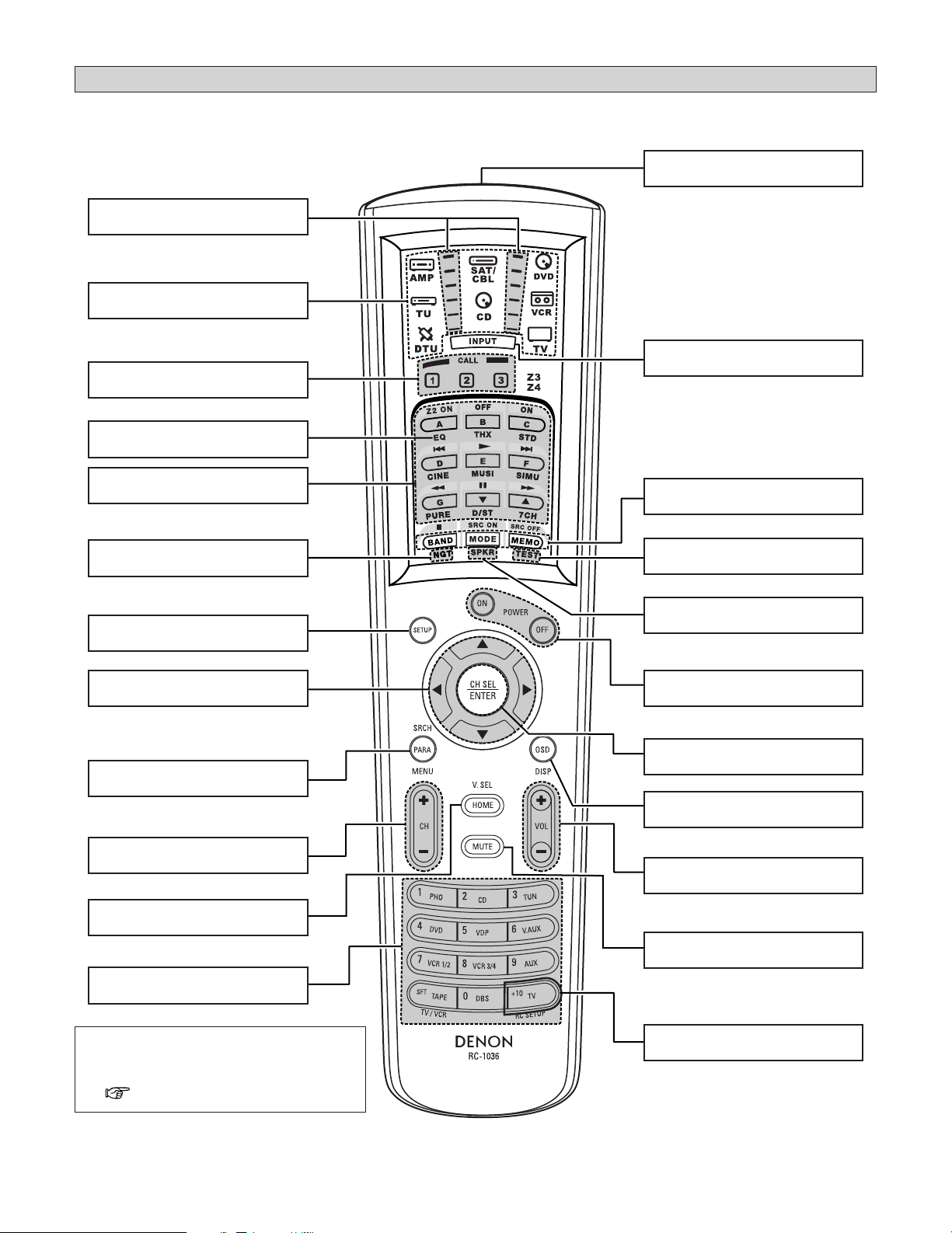
Remote control unit
• For details on the functions of these parts, refer to the pages given in parentheses ( ).
IR segment
·······················································(82)
MODE SELECTOR buttons
·······················································(81)
USER MODE/SYSTEM
CALL buttons ·························(60, 84)
ROOM EQ button
·······················································(48)
Getting Started
Remote control signal transmitter
·························································(9)
INPUT MODE selector button
·······················································(47)
Surround mode/System
buttons ···································(50, 83)
NIGHT button
·······················································(55)
SYSTEM SETUP button
·······················································(22)
CURSOR buttons
·······················································(22)
SURROUND PARAMETER/SEARCH
button·······························(51, 67, 73)
Tuner system buttons
·······················································(65)
HOME/VIDEO SELECT button
·················································(46, 81)
FUNCTION/NUMBER
buttons ···································(44, 82)
Tuner system buttons
·······················································(65)
TEST TONE button
···············································(95, 145)
SPEAKER button
·······················································(45)
Power buttons
·······················································(22)
CH SELECT/ENTER button
·················································(22, 64
ON SCREEN button
·······················································(46)
Master volume control buttons
·······················································(44)
MUTE button
·······················································(45)
)
NOTE:
• For instructions on setting the remote
control unit back light’s lighting time
( page 85).
RC SETUP button
·······················································(82)
13
Page 14
Easy Setup and Operation
• This section contains the basic steps necessary to configure the AVR-5805CI according to your listening room environment and
the source equipment and loudspeakers you are using.
• For optimum performance, we recommend using the Auto Setup function.
• If you wish, you can set the various settings manually without using Auto Setup ( page 140 ~ 148).
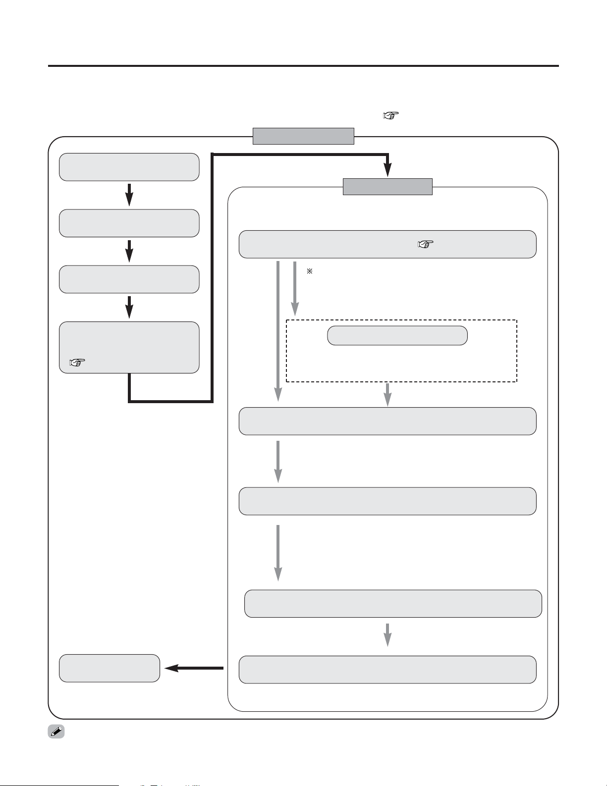
Easy to setup flow
Placing the speakers.
Auto setup flow
Perform the auto setup procedure, following the
Connecting the speakers.
instructions displayed on the TV’s screen.
Connecting a microphone ( page 21).
Connect the DVD player to the
AVR-5805CI.
Connect the AVR-5805CI’s
monitor output terminal to
the TV’s video input terminal
( page 19).
By default, the speaker system setting is set
to 9.1 channels.
Please set under “Extra Setup”, only when
you want to change this arrangement.
Extra Setup
1) Channel Setup
2) Power Amplifier Assignment
Perform the preliminary measurements.
1) Measuring the background noise (noise in the room).
2) Determining whether or not speakers are connected.
3) Checking the polarities of the speakers.
The measurement of the speakers in the main listening position.
1) Speaker Configuration
2) Delay Time (speaker distance)
3) Channel Level
4) Crossover Frequency
5) Room EQ
The measurement of the speakers
in the 2nd to 8th listening position.
Play a DVD.
Store the measurement result in the memory.
• Do not plug in the power supply cord until all connections have been completed.
Check of the measurement result.
14
Page 15
Easy Setup and Operation
AA
BB
AA
BB
SB SB SB SB
BB
SB SB
AA
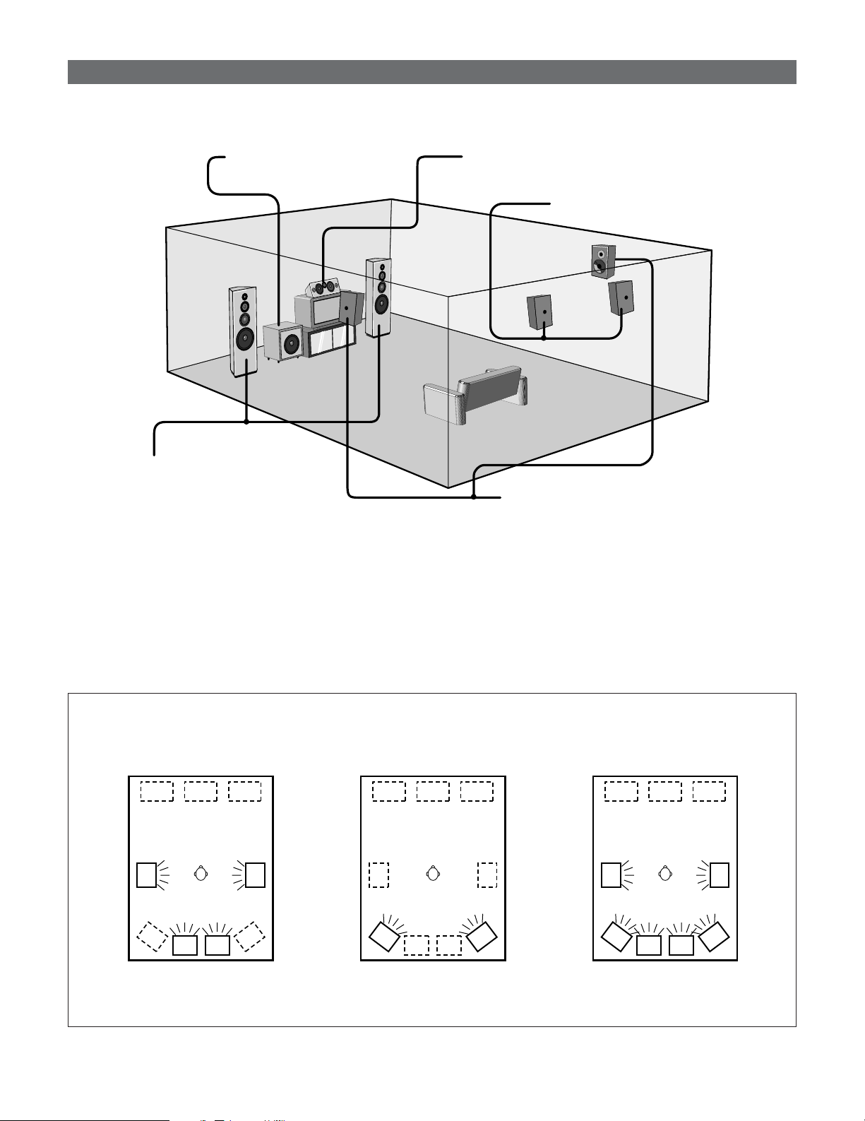
Speaker system layout
2 Basic system layout (For a THX Ultra2 system)
• The following is an example of the basic layout for a system consisting of eight speaker systems and a television monitor:
Subwoofer Center speaker system
Surround back speaker systems
Front speaker systems
Set these at the sides of the TV or screen
with their front surfaces as flush with the
front of the screen as possible.
Two surround back speakers are required to use the THX Ultra2 Cinema,THX Music mode and THX Games mode.
Set the surround back speakers so that the distance to the listening position is the same for both the left and right speakers. It is
also recommended that the deviations of the distance from the listening position to L and R channel speakers (front left (FL) and
front right (FR), surround left (SL) and surround right (SR), surround back left (SBL) and surround back right (SBR)) is less than 2
ft (60 cm).
With the AVR-5805CI it is also possible to use the surround speaker selector function to choose the best layout for a variety of
sources and surround modes.
2 Surround speaker selector function
This function makes it possible to achieve the optimum sound fields for different sources by switching between two
systems of surround speakers (A and B). The settings of the different speakers (A only, B only or A+B) are stored in the
memory for the different surround modes, so they are set automatically when the surround mode is selected.
Surround speaker systems
Using A only
(Multi surround speaker system)
Using B only
(Single surround speaker system)
(SB: Surround Back Speakers)
15
Using A and B
Page 16
Easy Setup and Operation
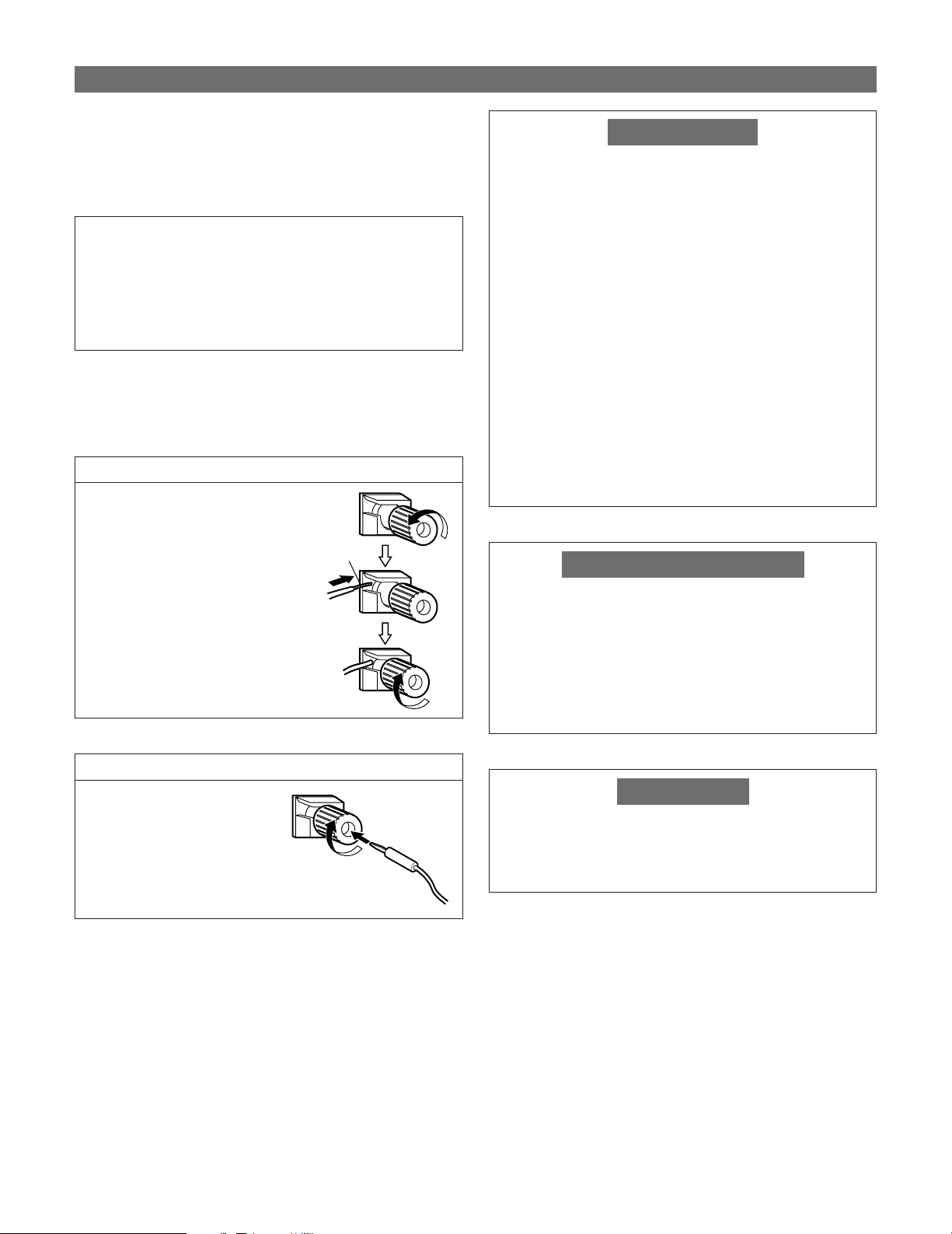
Speaker connections
• Connect the speaker terminals with the speakers making
sure that like polarities are matched (
Mismatching of polarities will result in weak central sound,
unclear orientation of the various instruments, and the
sense of direction of the stereo being impaired.
NOTE:
• NEVER touch the speaker terminals when the power
is on. Doing so could result in electric shocks.
• When making connections, take care that none of the
individual conductors of the speaker cable come in
contact with adjacent terminals, with other speaker
cable conductors, or with the rear panel and screws.
2
Speaker Impedance
• Speakers with an impedance of from 6 to 16 Ω/ohms can
be connected.
with <, >with >).
<
Connecting the speaker cables
1. Loosen by turning
counterclockwise.
Either tightly twist or terminate the core wires.
2. Insert the cable.
3. Tighten by turning clockwise.
Protector circuit
This unit is equipped with a high-speed protection circuit.
The purpose of this circuit is to protect the speakers under
circumstances such as when the output of the power
amplifier is inadvertently short-circuited and a large current
flows, when the temperature surrounding the unit
becomes unusually high, or when the unit is used at high
output over a long period which results in an extreme
temperature rise.
When the protection circuit is activated, the speaker output
is cut off and the power supply indicator flashes. Should
this occur, please follow these steps: be sure to switch off
the power of this unit, check whether there are any faults
with the wiring of the speaker cables or input cables, and
wait for the unit to cool down if it is very hot. Improve the
ventilation condition around the unit and switch the power
back on.
If the protection circuit is activated again even though there
are no problems with the wiring or the ventilation around
the unit, switch off the power and contact a DENON
service center.
Note on speaker impedance
The protector circuit may be activated if the set is played for
long periods of time at high volumes when speakers with
an impedance lower than the specified impedance (for
example speakers with an impedance of lower than 4
Ω/ohms) are connected. If the protector circuit is activated,
the speaker output is cut off. Turn off the set’s power, wait
for the set to cool down, improve the ventilation around the
set, then turn the power back on.
Connecting banana plugs
Turn clockwise to tighten, then
insert the banana plug.
Cooling fan
The AVR-5805CI is equipped with a cooling fan to prevent
the temperature inside the set from rising. The fan is
activated under certain usage conditions. It is temperature
sensitive, to minimize or prevent audible fan noise.
16
Page 17
Easy Setup and Operation
>< <>
><
><
>< <>
<>
>< <>
IN
(L)
(R)
(R) (L)
(L)
(R) (L)
(R)
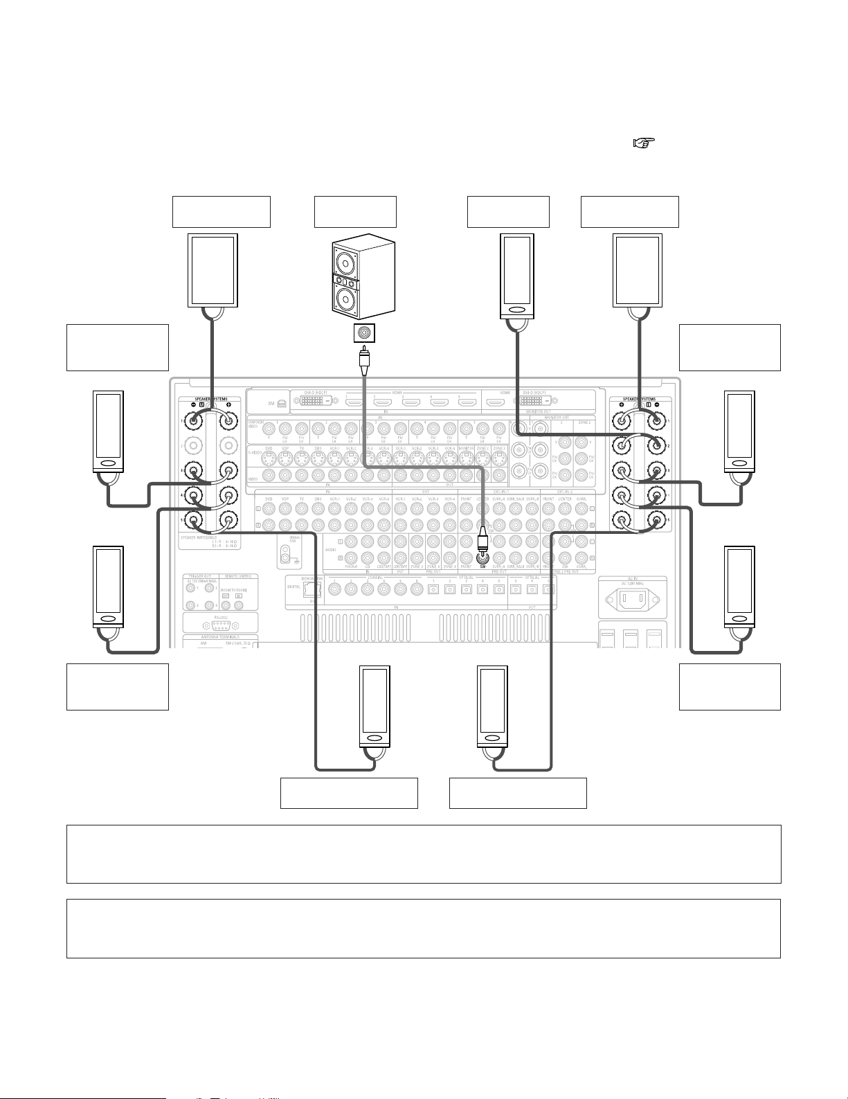
2 Connections
• By default, the speaker system setting is set to 9.1 channels.
• The AVR-5805CI can be configured for 10 speaker playback using two pairs of surround speakers (A+B) and one pair of
surround back speakers as shown below.
• The output of each power amplifier can be assigned to any desired channel to best suit the application.
For details, refer to “Setting the Channel Setup” and “Setting the Power Amplifier Assignment” ( page 129 ~ 133).
• When making connections, also refer to the operating instructions of the other components.
Example: 9.1 channel connections
Surround
right speaker
(A)
Front
right speaker
Subwoofer
Center
speaker
Connection
terminal for
subwoofer with
built-in amplifier
(subwoofer), etc.
Front
left speaker
Surround
left speaker
(A)
Surround
right speaker
(B)
Surround back
• Precautions when connecting speakers
If a speaker is placed near a TV or video monitor, the colors on the screen may be disturbed by the speaker’s magnetism. If
this should happen, move the speaker away to a position where it does not have this effect.
NOTE:
• Route the connection cables, etc., in such a way that they do not obstruct the ventilation holes.
• When using only one surround back speaker, connect it to left channel (L5).
right speaker
Surround back
left speaker
Surround
left speaker
(B)
17
Page 18
Easy Setup and Operation
DVD player
S VIDEO
OUT
COAXIAL
OUT
R
L
AUDIO OUT
VIDEO
OUT
COMPONENT VIDEO OUT
Y
P
B
PR
HDMI
OUT
DVI-D
OUT
R
L
R
L
H
J
I
A
C
M
L
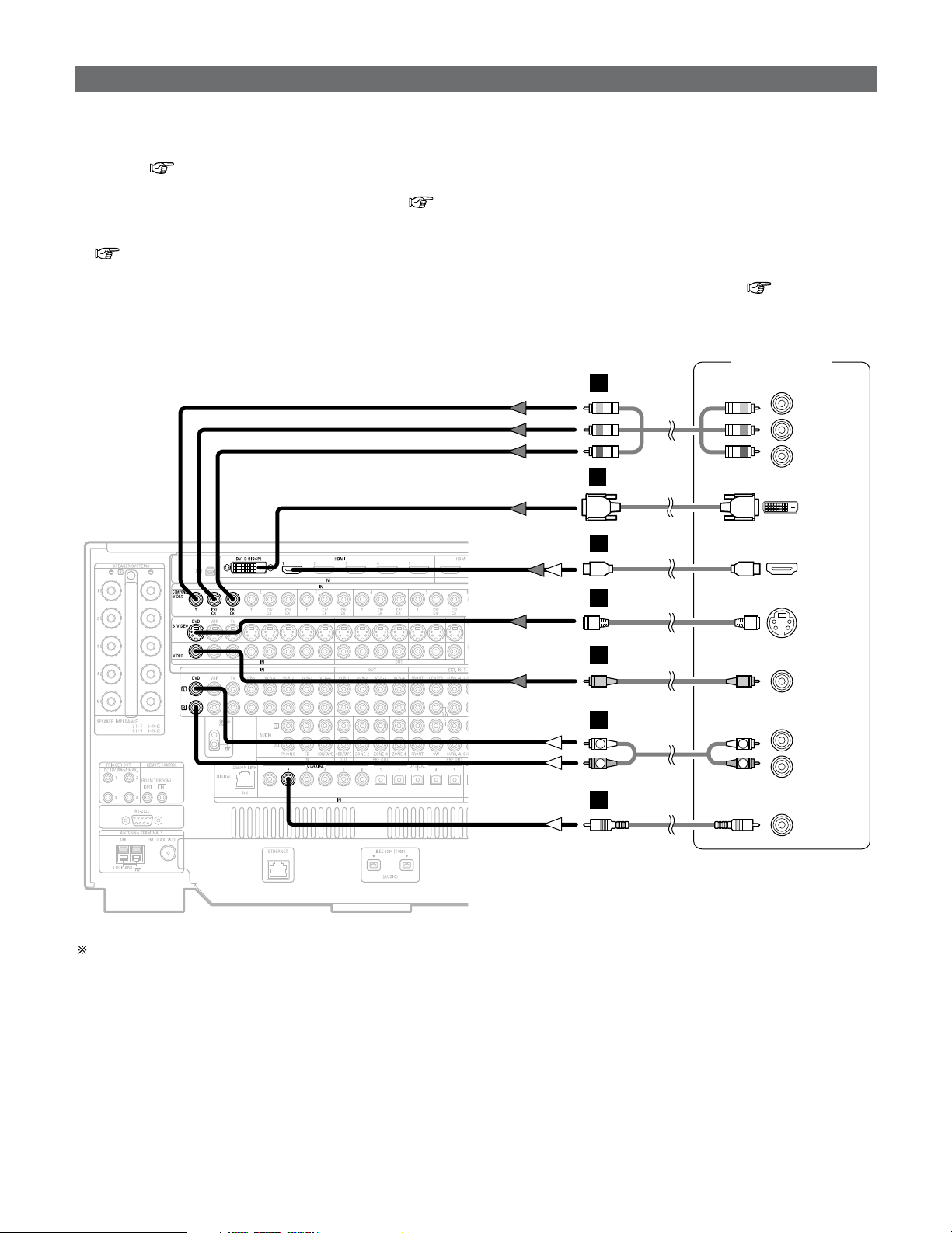
Connecting a DVD player and TV (Monitor)
•To connect the video output from the DVD player to the AVR-5805CI, you only need to choose one connection type. Component
video connection offers the best quality (and is required for progressive DVD playback), followed by S-Video, while composite
video offers the lowest picture quality of the three connection types. For more information about the video up conversion
function ( page 28).
• The AVR-5805CI is equipped with HDMI terminals, so it can be connected to a DVD player or TV (monitor) using an HDMI cable.
To connect it to a DVD player using a DVI-D cable ( page 37).
• The AVR-5805CI is equipped with a BNC terminal, so a DVD player or monitor can be connected using a BNC cable.
If you choose to use the BNC connection, it needs to be assigned. For more information about Component Input Assignment
( page 112).
•To connect the digital audio output from the DVD player, you can choose from either the coaxial or optical connections. If you choose
to use the optical connection, it needs to be assigned. For more information about Digital Input Assignment ( page 104).
• The AVR-5805CI is equipped with another set of input terminals for a non-DVD Video Disc Player (such as laser disc, VCD/SVCD,
or future high definition disc player). The above connection guidelines for DVD also apply to the VDP input.
Audio signal flow is shown with white arrows, video signal flow is shown with gray arrows.
18
Page 19
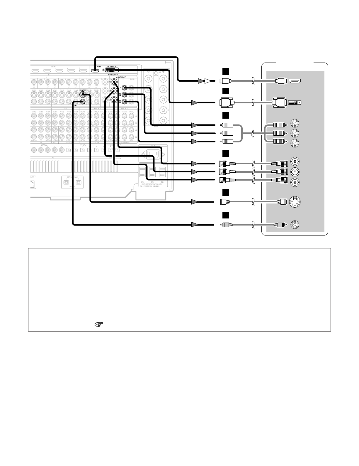
Easy Setup and Operation
TV (Monitor)
S VIDEO
IN
VIDEO
IN
COMPONENT VIDEO IN
Y
P
B
PR
HDMI
IN
DVI-D
IN
COMPONENT VIDEO OUT
Y
PB
PR
H
J
I
M
L
K
or
• For best picture quality (especially with progressive DVD and other high definition sources) choose the component video or
HDMI connection to your monitor or TV. S-Video and composite video outputs are also provided if your TV does not have
component video inputs.
NOTE:
• The component video input and/or output terminals may be labeled differently on some TVs, monitors or video
components (Y, P
B, P
R; Y, CB, CR; Y, B-Y, R-Y). Check the operating instructions for other components for further
information.
• The COMPONENT MONITOR OUT-1 and the COMPONENT MONITOR OUT-2 can be used simultaneously. Connect with
a BNC cable when using the COMPONENT MONITOR OUT-1 terminal, a component video cable when using the
COMPONENT MONITOR OUT-2 terminal.
•The HDMI and DVI-D monitor output terminals on the AVR-5805CI can only be used one at a time, not simultaneously.
• Audio signals are only output from the HDMI monitor out connector when audio signals are input to the HDMI input
connector.
• When connecting the AVR-5805CI and DVD player using an HDMI cable, also connect the AVR-5805CI and monitor or TV
using an HDMI cable ( page 36).
19
Page 20
Easy Setup and Operation
*
M
*
M
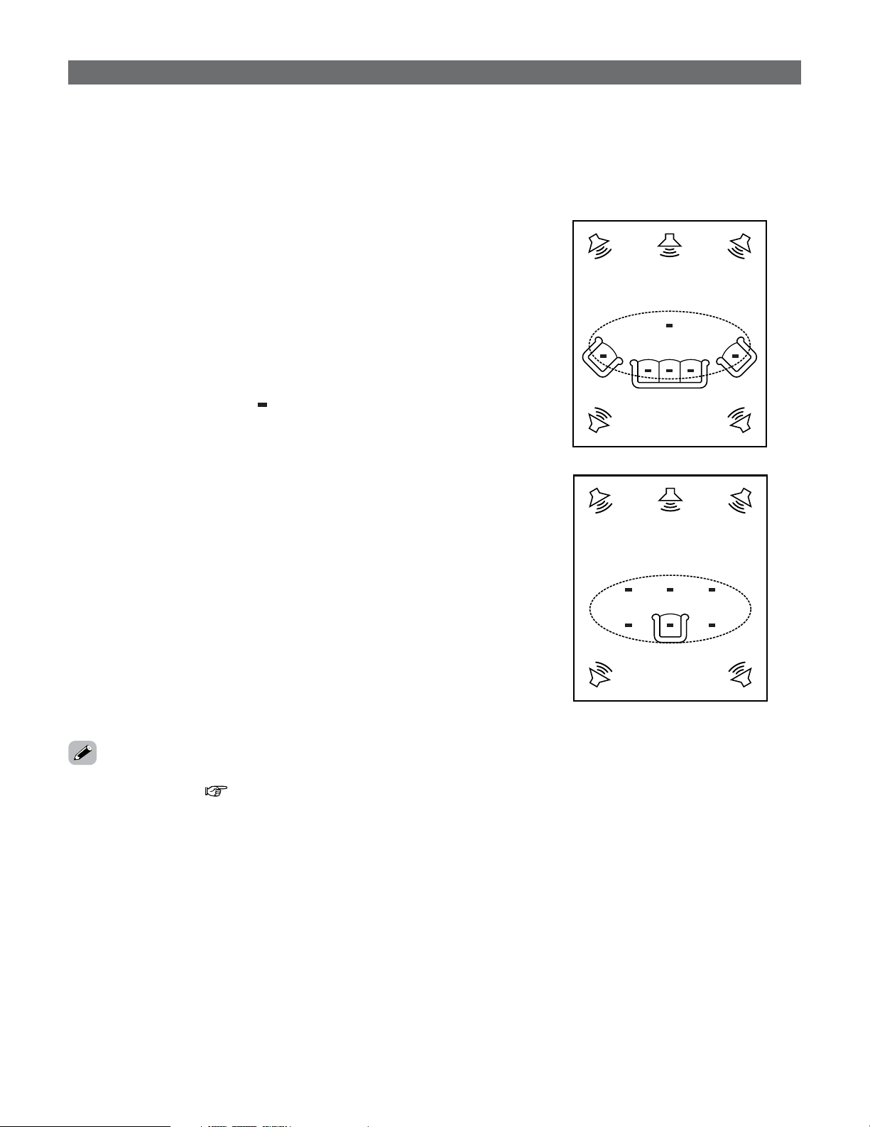
Auto Setup / Room EQ
The Auto Setup and Room EQ function of this unit performs an
analysis of the speaker system and measures the acoustic
characteristics of your room to permit an appropriate automatic
setting.
The AVR-5805CI’s Audyssey MultEQ XT function has the
feature that it provides the optimum listening environment at
all listening positions in the home theater, where there are
often multiple listeners viewing programs together. To achieve
this, it is first necessary to use a microphone to measure test
tones generated from the different speakers at the various
listening positions. All this measured data is analyzed with a
unique method to comprehensively improve acoustic
characteristics in the listening area. For optimum
effectiveness, measurements should be performed at six or
more points. Move the microphone successively within the
listening area surrounded by the speakers as shown on the
diagram below to measure the test tones. When listening to
music or viewing movies with the whole family, move the
microphone successively to the different positions in which
the members of the family sit (“ ” on the diagram indicates
the points of installation) and measure repeatedly (Example
q). Even if the number of people using the home theater is
small, taking multiple measurements at or near the listening
positions makes it possible to correct the sound more
effectively (Example w).
The AVR-5805CI’s Room EQ function offers three correction
curves: “Audyssey”, “Front” and “Flat”. These can be
selected after performing the auto setup procedure. Details of
the different correction curves are described below.
• Audyssey:
This adjusts the frequency response of all speakers to
correct the effects of room acoustics.
• Front:
This adjusts the characteristics of each speaker to the
characteristics of the front speakers.
• Flat:
Makes the frequency response for all the speakers flat.
This is suitable for multi-channel music reproduction, from
discrete music sources such as Dolby Digital 5.1, DTS, DVDAudio and Super Audio CD.
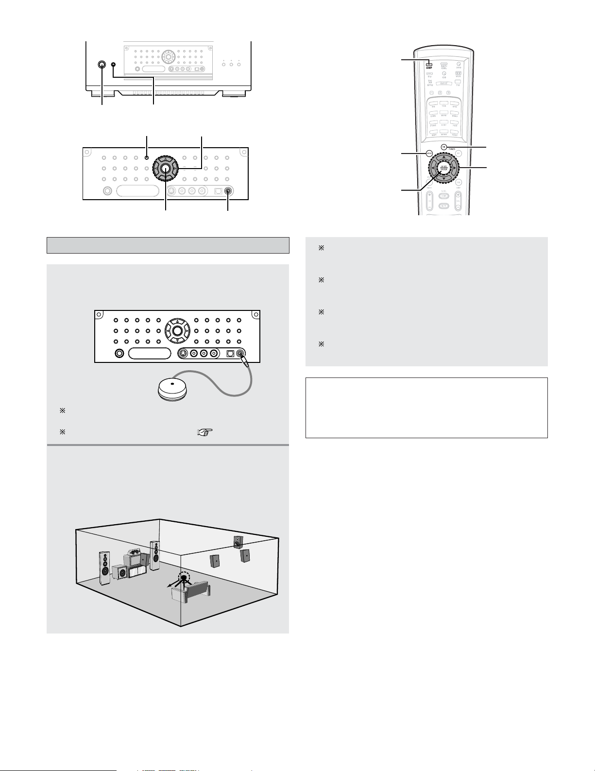
2 About the main listening position (*M)
• The main listening position is the point where a listener
sits most often or the listening position when only one
person is listening. Measurements on the AVR-5805CI
start from this point. Correction for the speaker distance
(“Delay Time”) is set based on this point.
Example: q
Example: w
•To make the Speaker system settings without using the
Auto Setup function ( page 140 ~ 148).
20
Page 21
Easy Setup and Operation
ON/STANDBY
POWER
AMP
ON
SYSTEM SETUP
CURSOR
ENTER
SYSTEM SETUP
SETUP MIC
ENTER
CURSOR
Connecting a microphone
Connect the optional microphone for Auto
Setup to the
1
SETUP MIC jack on the front
panel of the unit.
The optional standard microphone is DENON DM-S305
sold separately.
When using other microphone ( page 150, 151).
Mount the auto setup microphone onto a
camera tripod, etc., and place it at ear height
2
at the main listening position in the listening
room with the sound receptor facing the
ceiling.
When placing the microphone, adjust the height so
that the microphone’s sound receptor is at the height
of the ears of the listener.
Be sure that at the beginning, the measurement is
started with the microphone set up at the main
listening position.
It is not possible to measure properly if there are any
obstacles between the speakers and microphone.
Check that there are no obstacles.
Please do not stand between or near the speakers and
the microphone during the measurements.
NOTE:
• Do not disconnect the microphone until the settings are
completed.
• Do not change the connection of speakers or the
subwoofer’s volume after performing these measurements.
Microphone
21
Page 22
Easy Setup and Operation
Turning on the power
Turn on your subwoofer.
1
Set the volume to halfway and set the crossover
frequency to the maximum or Low pass filter off if your
subwoofer can adjust the output volume and the
crossover frequency.
Some subwoofers have a standby mode. Be sure to
turn this function off before performing the Auto Setup
procedure.
Turn on your TV (monitor).
2
Press the POWER switch.
3
¢ ON:
The power turns on and the power indicator lights.
Set the POWER switch to this position to turn the
power on and off from the included remote control
unit.
£ OFF:
The power turns off and indicator is off.
In this position, the power cannot be turned on and
off from the remote control unit.
Press the ON/STANDBY switch on the main
4
unit or
• When pressed, the power turns on and the display
• When pressed again, the power turns off, the
ON button on the remote control unit.
lights.
standby mode is set and the display turns off.
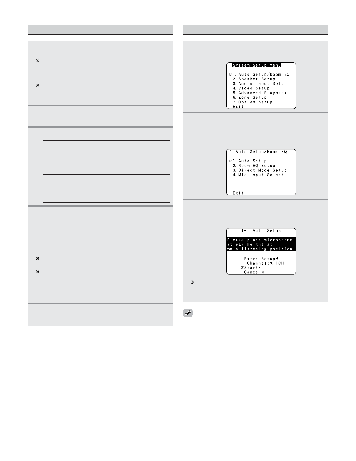
Starting Auto Setup
Press the SYSTEM SETUP button.
• The “System Setup Menu” appears.
1
Press the CURSORDDorHHbutton to select
2
“Auto Setup / Room EQ”, then press the
ENTER button.
• The “Auto Setup / Room EQ” menu appears.
Press the CURSORDDorHHbutton to select
3
“Auto Setup”, then press the
• The “Auto Setup” screen appears.
ENTER button.
The sound is muted for several seconds, after which
the unit operates normally.
Whenever the ON/STANDBY button is in the standby
state, the apparatus is still connected to the AC line
voltage. Please be sure to turn off the POWER switch or
unplug the cord when you leave home for, say, a
vacation.
Press the AMP button to select “AMP” (only
5
when operating with the remote control unit).
The message “Connect Microphone” is displayed if no
microphone is connected. If so, connect the auto setup
microphone.
• If no operation is performed for approximately 3 minutes
during the auto setup procedure, the screensaver is
launched. The screensaver is canceled if any one of the
CURSOR, ENTER or SYSTEM SETUP button is pressed.
22
Page 23
Easy Setup and Operation
Extra Setup
• The AVR-5805CI has ten available amplifier channels, some
of which can be assigned for powering speakers in ZONE2,
ZONE3 and ZONE4 depending on the speaker system
complement in the main room. If this functionality is not
needed, skip this “Extra Setup” procedure and proceed to
“Preliminary Measurements”.
• By default, the speaker system setting is set to 9.1 channels.
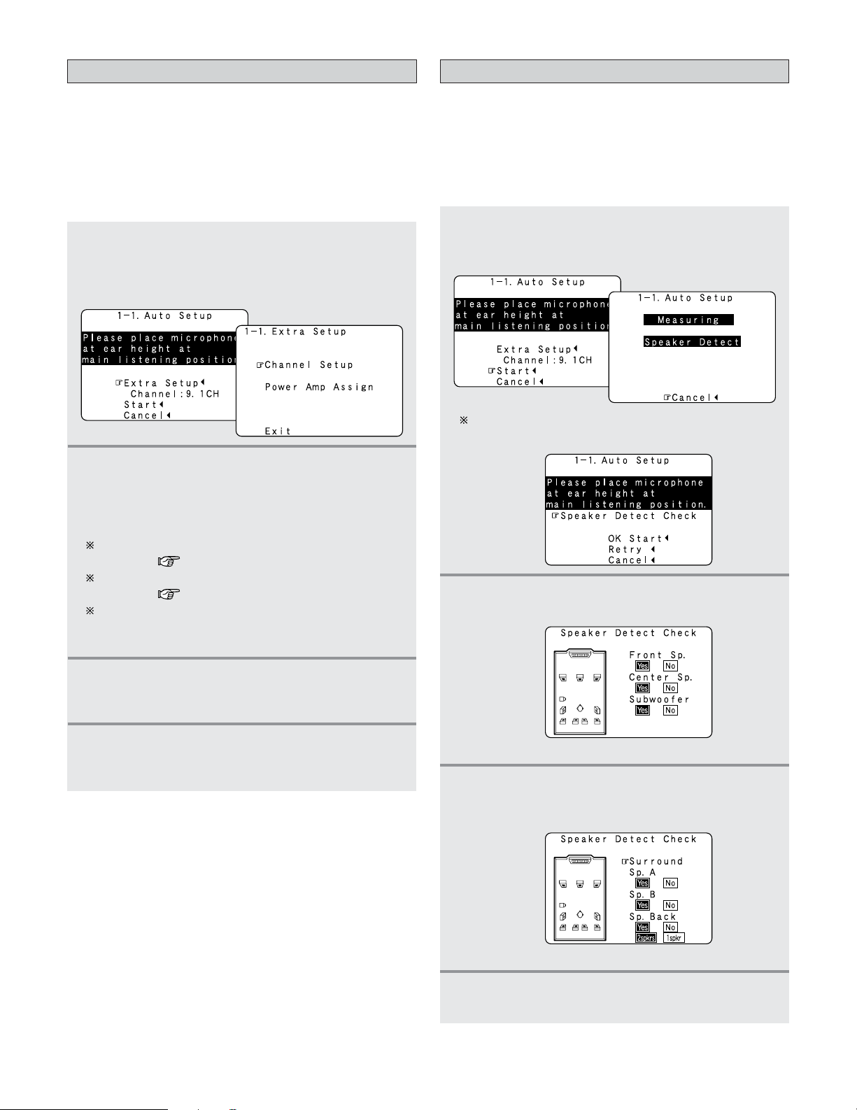
Press the CURSORDDorHHbutton to select
1
“Extra Setup”, then press the
button.
•Switch to the “Extra Setup” screen.
Press the CURSORDDorHHbutton to choose the
2
setting you want to change, then press the
ENTER button.
•Switch to the setting screen.
CURSOR
FF
Preliminary measurements
• This procedure is used to automatically determine the
background noise, whether or not speakers are connected,
and the polarities of the connected speakers.
•To avoid affecting the measurements, turn off the airconditioner or any other device that makes noise and take
the measurements with the room as quiet as possible.
Press the CURSORDDorHHbutton to select
1
“Start”, then press the
• Start the preliminary measurements.
The screen shown at the below appears once the
preliminary measurements are completed.
CURSOR
FF
button.
For instructions on making the “Channel Setup”
settings ( page 126 ~128).
For instructions on making the “Power Amp Assign”
settings ( page 129 ~ 133).
The speakers measured with this Auto Setup
procedure are based on the setting of these “Channel
Setup” and “Power Amp Assign” functions.
Once the settings are completed, press the
ENTER button at the each setting screen.
3
• The “Extra Setup” screen reappears.
Press the CURSORDDorHHbutton to select
4
“Exit”, then press the
• Return to the “Auto Setup” screen.
ENTER button.
Press the ENTER button.
• Switch to the “Speaker Detect Check” screen.
2
[ First screen ]
Check the results of the speaker detection,
then press the
3
• Switch to the second screen.
ENTER button.
23
[ Second screen ]
If the check ends, press the ENTER button
4
again.
Page 24
Easy Setup and Operation
NOTE:
• If the results are not as expected or if an error message is
displayed, select “Retry” and perform the measurements
again. (For details on the error messages ( page 26).)
If the results of remeasurement are still not as expected
or if an error message is displayed, turn off the power
switch and check the speaker connections. Then start the
measurements again from the beginning.
• Measurement is cancelled when MASTER VOLUME is
operated while the Auto Setup is performed.
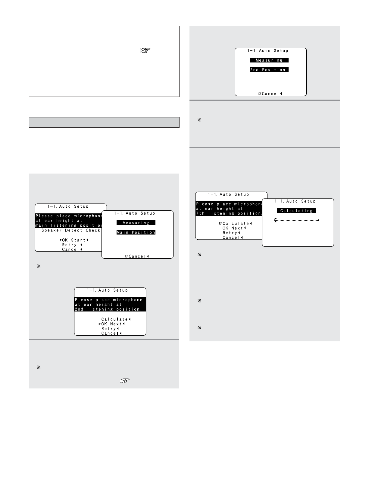
Speaker system measurement
•With these measurements, the “Speaker Configuration”,
“Delay Time”, “Channel Level”, “Crossover Frequency” and
“Room EQ” are analyzed automatically. The main listening
position is measured first, so leave the microphone where it
is.
Press the CURSORDDorHHbutton to select “OK
1
Start”, then press the
• Measurements for the first point start.
CURSOR
FF
button.
Press the CURSORFFbutton.
• Measurements for the second point start.
3
Perform step 2, 3 repeatedly.
4
The more measurement points, the better the
resulting room correction effect. We recommend a
minimum of 6 measurement points – 8 measurement
points provides the best room correction effect.
After measuring at the number of points
according to your listening environment, press
5
the
CURSOR
“Calculate”, then press the
• The speaker system is analyzed.
DD
or
HH
button to select
CURSOR
FF
button.
The screen shown at the below appears once the
measurements for the main listening position are
completed.
Next the measurements for the second point
will be taken.
2
Place the microphone at the second listening position.
For instructions on the position in which the
microphone should be placed ( page 20).
The amount of time required for the analysis depends
on the number of speakers and the number of
measuring points. The greater the number of speakers
and measuring points, the longer the time required. For
example, for ten speaker systems and 6 measuring
points, the calculations require approximately 6
minutes.
Measurements can be ended when there are 5 or less
measurement locations; however, to obtain better
results, measurements at 6 or more locations is
recommended.
Once the calculations are completed, a screen for
confirming the results of the measurements appears.
24
Page 25
Easy Setup and Operation
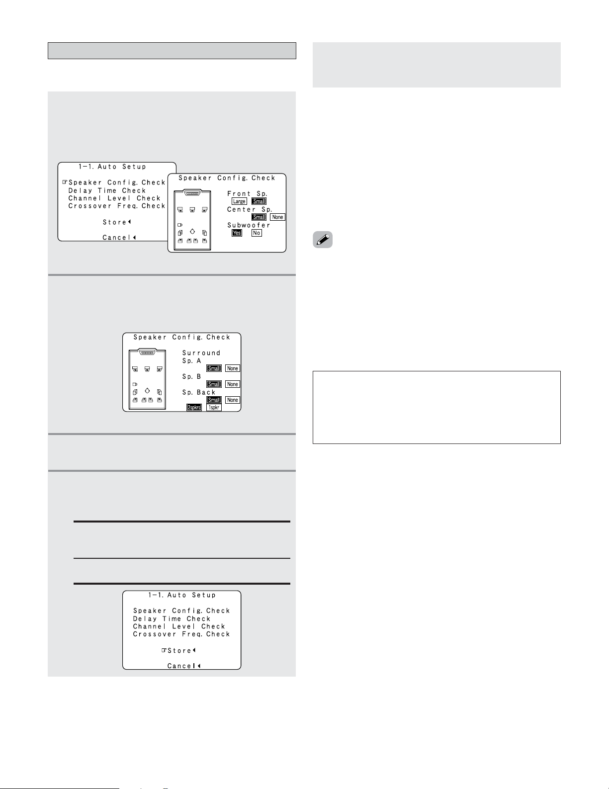
Check of the measurement result
• The results of the measured items can be checked.
Press the CURSORDDorHHbutton to select
1
items, then press the
• Switch to the verification screen.
Example: Speaker Config. Check
Press the ENTER button.
• Switch to the second screen.
2
Example: Speaker Config. Check
ENTER button.
[ First screen ]
Press the CURSOR
•After the data is stored, the “Auto Setup / Room
5
• Sometimes due to the electrical complexities of subwoofers
• Sometimes due to interaction with the room, you may notice
• Please note that any THX main speakers should be set to
• When measurements have been made using the
• If the “Channel Setup” or “Power Amplifier Assignment”
EQ” menu appears automatically.
and the interaction with the room, THX recommends setting
the level and the distance of the subwoofer manually.
irregular results when setting the level and/or distance of the
main speakers. If this happens, THX recommends setting
them manually.
Small (80 Hz). If you set up your speakers using Auto Setup,
please make sure manually that any THX speakers are set to
Small with 80 Hz crossover.
measurement microphone, speakers with a built-in filter
such as subwoofers might be set with a value that differs
from the physical distance because of the internal electrical
delay.
settings are changed after completing the auto setup,
perform the auto setup procedure again. In the same way, if
the speaker layout has been changed, we recommended
performing the auto setup procedure over again.
FF
button.
[ Second screen ]
If the check ends, press the ENTER button
3
again.
Press the CURSORDDorHHbutton to select
4
whether or not to save the data you have
checked.
Store:
Set with the checked measurement value.
All parameters are stored up.
Cancel:
Cancel the auto setup settings.
NOTE:
• Do not turn off the power while the data is being stored.
If the power is turned off while the data is being stored,
the Room EQ parameters stored in the memory will be
cleared, and it will not be possible to select “Audyssey”,
“Front” or “Flat” equalizer settings.
25
Page 26
Easy Setup and Operation
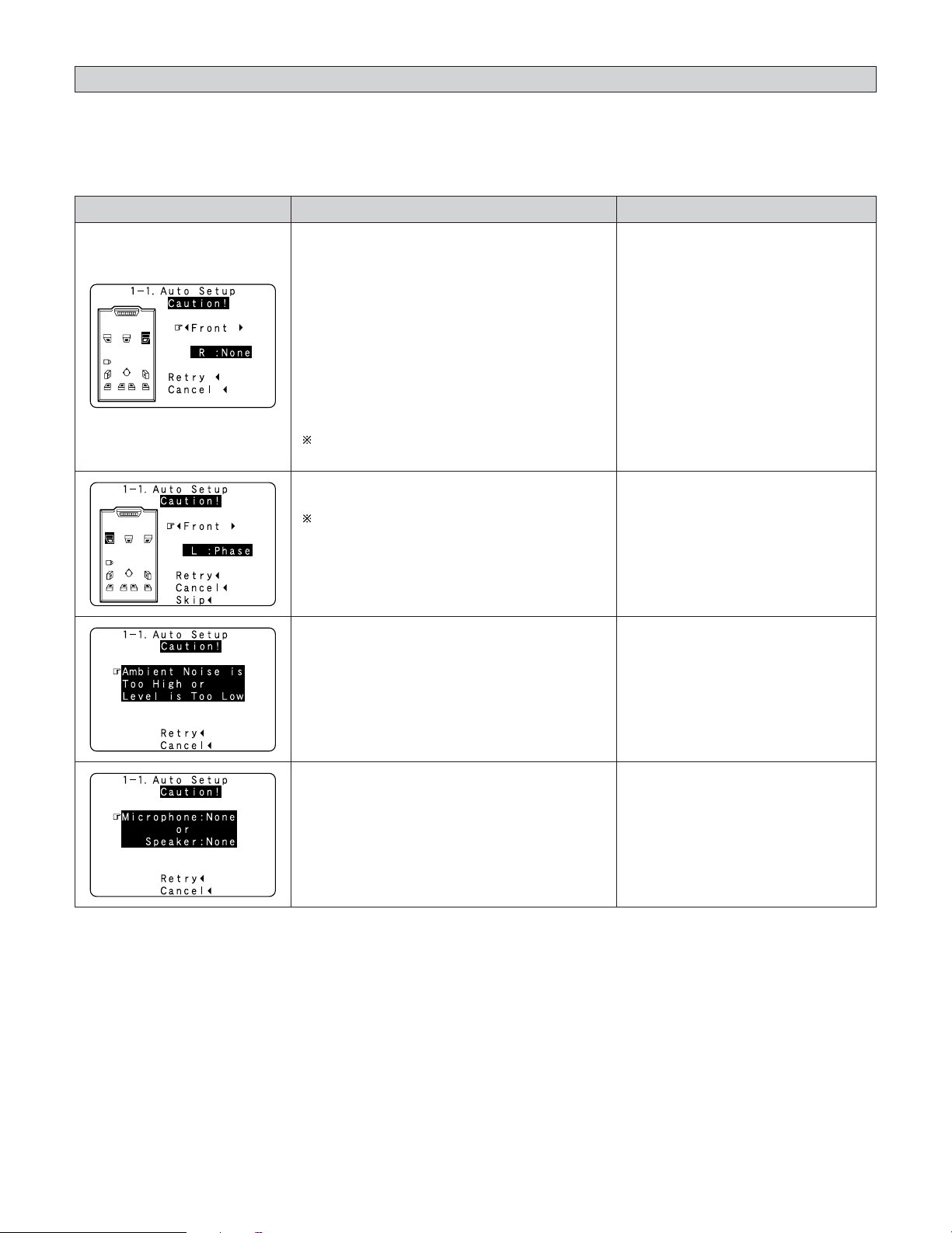
About the error message
• These error messages will be displayed when performing the measurements of Auto Setup and the automatic measurements
can not be completed because of the speaker arrangement, measurement environment, or other factors. Please check the
following matters, reset the pertinent items, and measure again. Be sure to turn off the AVR-5805CI’s power before checking
the speaker connections.
MeasuresCauseScreen example
q The speakers required for producing suitable
reproduction have not been detected.
• The front L speaker was detected, but the
front R speaker was not detected.
• Only one channel of the surround (A) and
surround (B) speakers was detected.
• Sound was output from the R channel when
only one surround back speaker was
connected.
• The surround back or the surround (B) speaker
was detected, but the surround (A) speaker
was not detected.
If multiple errors occur, press the CURSORFFor
GG
button to check the contents.
w The speaker polarity is connected in reverse.
If multiple errors occur, press the CURSORFFor
GG
button to check the contents.
• Check that the pertinent speakers
are properly connected.
• Check the polarity of the pertinent
speakers.
• For some speakers, the screen
below may be displayed even though
the speakers are properly connected.
If so, select “Skip
0
”.
e There is too much ambient noise in the room
and the measurements cannot be made
accurately.
r The sound level that is output from the
speakers and/or subwoofer is too low.
t The measurement microphone is not
connected, or all of speakers have not been
detected.
y The front L speaker was not detected.
• Either turn off the power of the
device that generated the noise
during the measurements or move
the device away.
•Try again at a time when it is quieter.
• Check the placement and orientation
of the loudspeakers.
• Adjust the subwoofer’s output level.
• Connect the measurement microphone
to the SETUP MIC jack.
• Check the speaker connection.
26
Page 27
Connecting Other Sources
R
L
R
L
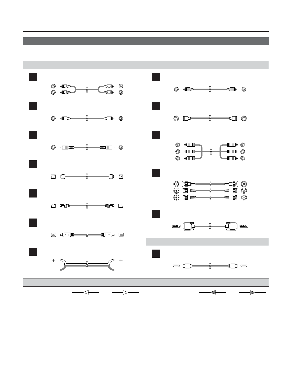
Cable indications
• The hookup diagrams on the subsequent pages assume the use of the following optional connection cables (not supplied).
Video cableAudio cable
Analog connections (Stereo)
A
(White)
(Red)
Pin-plug cable
Analog connections (Monaural, for subwoofer)
B
Pin-plug cable
Digital connections (Coaxial)
C
(Orange)
Coaxial cable (75 Ω/ohms pin-plug cable)
Digital connections (Optical)
D
Optical cable (Optical fiber cable)
DENON LINK connections
E
DENON LINK cable
IEEE1394 connections
F
Video connections
H
(Yellow)
Video cable (75 Ω/ohms video pin-plug cable)
S-Video connections
I
S-Video cable
Component video connections
J
(Green)
(Blue)
(Red)
Component video cable
Component video connections
K
(Y)
B/CB
)
(P
R/CR
(P
)
BNC (75 Ω/ohms) cable
DVI-D connections
L
(Y)
(PB/CB)
R/CR
(P
(Y)
B/CB
(P
R/CR
(P
)
)
)
4-pin, S400 IEEE1394 cable
Speaker connections
G
Speaker cable
M
Signal direction
Audio signal Video signal
NOTE:
• Do not plug in the power supply cord until all connections
have been completed.
• When making connections, also refer to the operating
instructions of the other components.
• Be sure to connect the left and right channels properly
(left with left, right with right).
• Note that binding pin-plug cables together with power
supply cords or placing them near a power transformer
will result in generating hum or other noise.
NOTE:
• Connecting a LD (laser disc) player with a Dolby
Digital RF Output
The AVR-5805CI does not have a DD RF demodulator
function. Therefore, you need to use a commercially
available outboard DD RF demodulator and connect its
digital output to one of the AVR-5805CI available digital
inputs. Refer to the demodulator’s operating instruction
for further information.
27
24-pin DVI-D cable
Audio and Video cable
HDMI connections
19-pin HDMI cable
IN OUT OUT ININ OUT OUT IN
Page 28
Connecting Other Sources
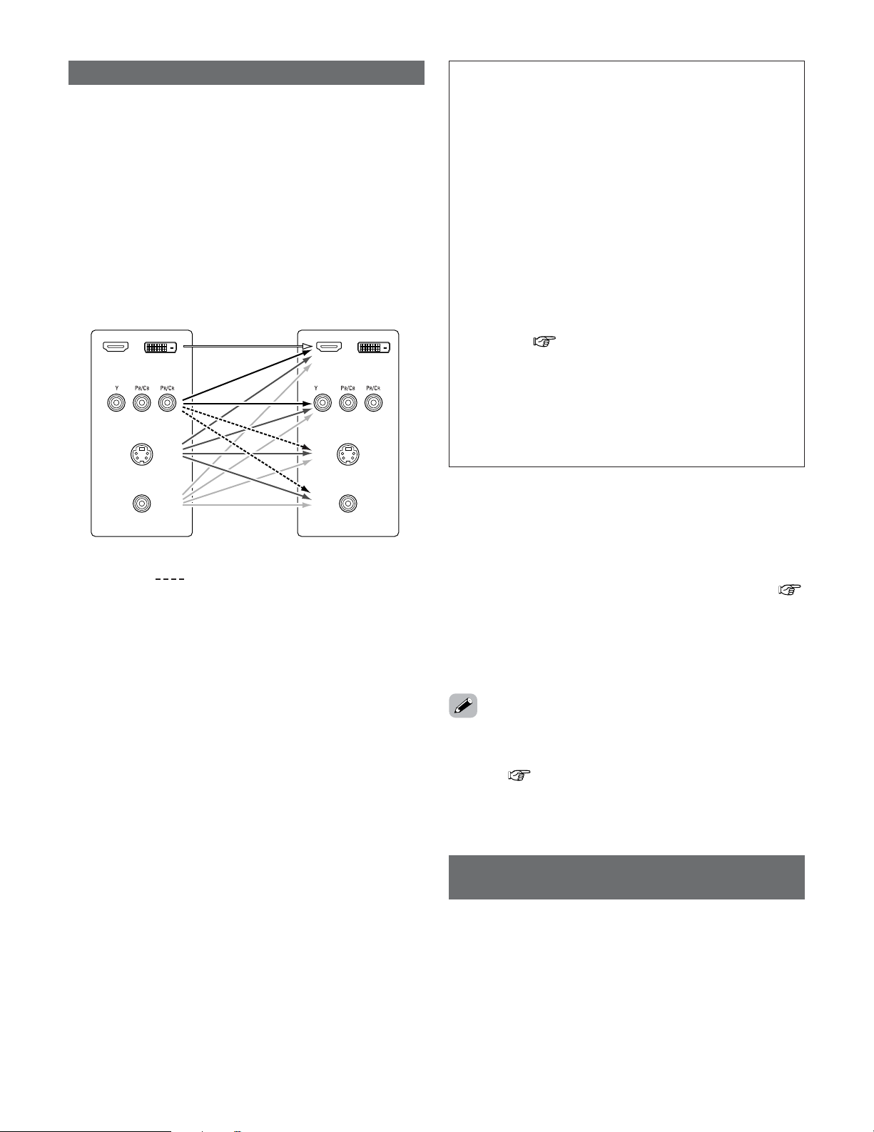
The video conversion function
• The AVR-5805CI is equipped with a function for up and down
converting video signals.
Because of this, the AVR-5805CI’s MONITOR OUT terminal
can be connected to the monitor (TV) with a set of cables
offering a higher quality connection, regardless of how the
player and the AVR-5805CI’s video input terminals are
connected.
Generally speaking, analog video connections using the
component video terminals offer the highest quality
playback, followed by connections using the S-Video
terminals, then connections using the regular video
terminals (yellow).
The flow of the video signals.
HDMI / DVI-D
terminals
Component video
terminals
S-Video terminal
Video terminal
AVR-5805CI’s input terminals AVR-5805CI’s output terminals
: only MAIN ZONE 480i/576i
Cautions on the ZONE2 video conversion function:
• There is no TBC (Time Base Collector) for ZONE2.
When the component video terminals are used to connect
the AVR-5805CI with a TV (or monitor, projector, etc.) and
the video (yellow) or S-Video terminals are used to connect
the AVR-5805CI with a VCR, depending on the combination
of the TV and VCR the picture may flicker in the horizontal
direction, be distorted, be out of sync or not display at all
when playing video tapes.
If this happens, connect a commercially available video
stabilizer, etc., with a TBC (time base corrector) function
between the AVR-5805CI and the VCR, or if your VCR has
a TBC function, turn it on.
HDMI / DVI-D
terminals
Component video
terminals
(MONITOR OUT/ZONE2)
S-Video terminal
(MONITOR OUT/ZONE2)
Video terminal
(MONITOR OUT/ZONE2)
NOTE:
• It is not possible to down-convert from HDMI and DVI-D
input signals to the component, S-Video or composite
video monitor output terminals.
•Video down conversion to the MAIN ZONE’s monitor
output is only possible when the component video input
resolution is 480i (interlaced standard definition video –
NTSC format, for North America) or 576i (interlaced
standard definition video – PAL format, for Europe and
other countries).
• It is not possible to down-convert from the ZONE2’s
component video signal to a S-Video or composite signal,
so when not using the ZONE2’s component monitor
output terminal, use an S-Video connection cable or
composite connection cable to connect the AVR-5805CI
with the player.
•To set the video conversion function for the MAIN ZONE
to “OFF” ( page 112).
• Set the resolution of the video output to one that is
compatible with the resolution of your monitor.
• When “Component” is set at “Scaler” under
“HDMI/Component Out”, the signals are output to the
HDMI/DVI-D monitor output terminal with their original
resolution. Use a monitor compatible with a resolution of
480i/576i.
2
The analog video to HDMI conversion function:
The AVR-5805CI’s video up-conversion function lets you
output analog video input signals (component – 480i/576i,
480p/576p, 1080i or 720p; S-Video and composite video 480i/576i) to the HDMI monitor output terminal.
•With the AVR-5805CI, the resolution of the signal output to
the HDMI MONITOR OUT terminal can be selected (
page 113, 114). The resolutions with which the monitor is
compatible can be checked using the STATUS button on the
main unit or the ON SCREEN button on the remote control unit.
• The resolution of the signal output to the component
monitor output terminal can be set on the AVR-5805CI.
• If you do not want to use the function for converting analog
video signals to HDMI signals, select “OFF” for “Analog to
HDMI Convert” at “Setting the HDMI/Component Out
Setup”( page 113, 114).
In this case, the function for video up conversion to the
component video terminal operates.
On screen display for component video
outputs and HDMI output
• When viewing component video signals or HDMI signals via
the AVR-5805CI, the on screen display is displayed on the
monitor when the “System Setup” operations are
performed and when the remote control unit’s ON SCREEN
button is operated.
•To view the on screen display using an HDMI monitor, set
“Analog to HDMI Convert” at “HDMI/Component Out” to
“ON” (default).
• When only component video signals are input to the AVR5805CI, the characters of the on screen display are not
displayed over the picture.
28
Page 29
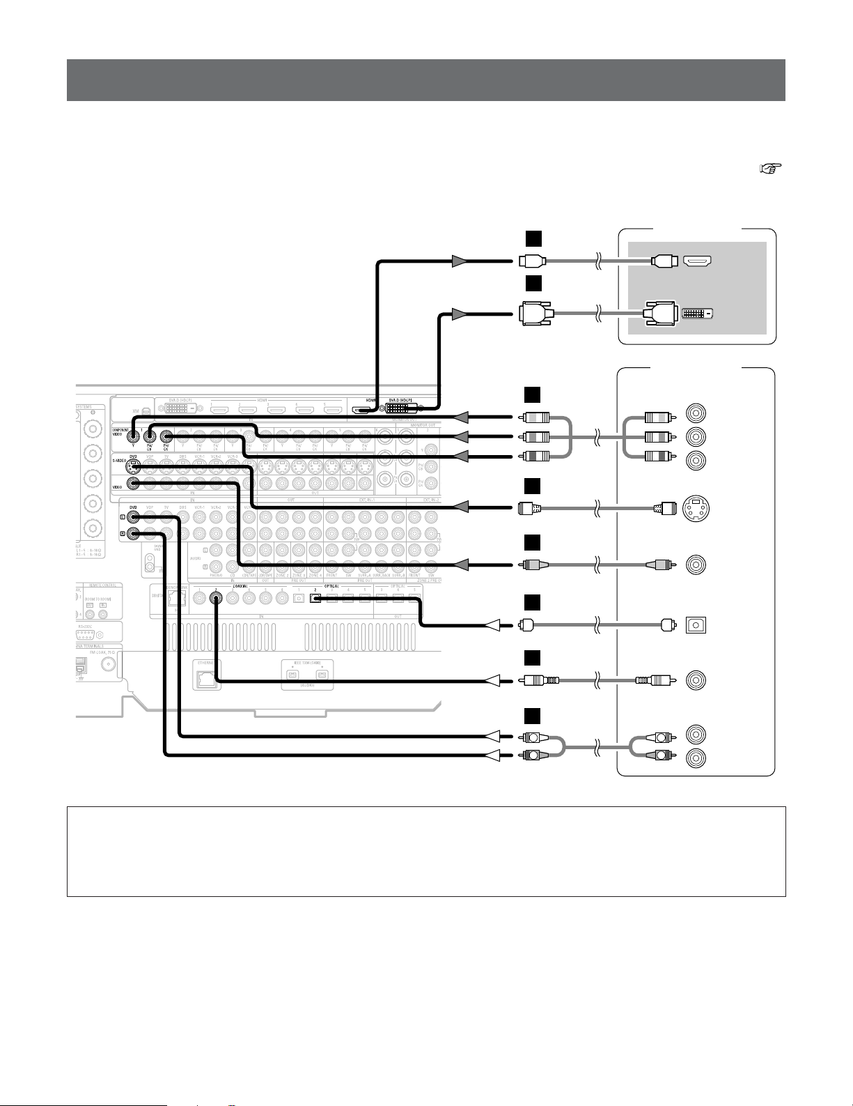
Connecting Other Sources
DVD player
S VIDEO
OUT
COAXIAL
OUT
R
L
AUDIO OUT
VIDEO
OUT
COMPONENT VIDEO OUT
Y
P
B
PR
OPTICAL
OUT
TV (Monitor)
HDMI
IN
DVI-D
IN
or
R
L
R
L
H
J
I
A
C
D
M
L
Connecting equipment with HDMI terminals
[To convert analog video signals to HDMI signals]
• The AVR-5805CI is equipped with a function for converting analog video signals into HDMI signals.
You can do this by either a component or a video or a S-Video connection.
• Audio signals are not output from the HDMI monitor output terminal, so also make analog or digital audio connections. To play
sound using digital audio connections, assign the digital terminal (coaxial or optical) at “Setting the Digital In Assignment” (
page 104).
NOTE:
• When “Through” is set at “Resolution” under “Setting the HDMI/Component Out Setup”, use a monitor compatible with
input resolutions of 480i/576i.
• If your monitor is not equipped with an HDMI terminal, connect the AVR-5805CI to the monitor using the component
video, S-Video, or composite video terminals.
29
Page 30
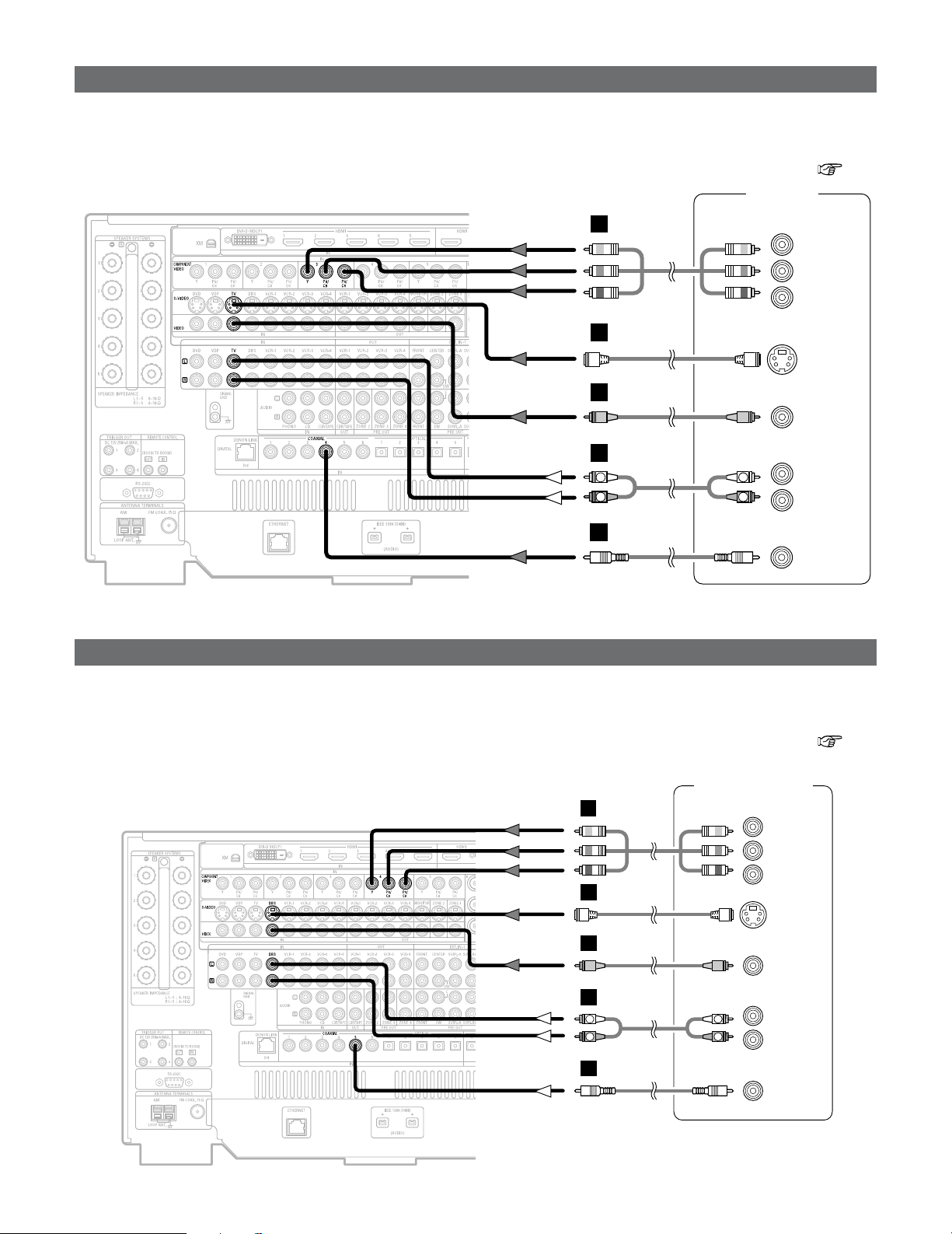
Connecting Other Sources
H
I
A
TV tuner
S VIDEO
OUT
R
L
AUDIO OUT
VIDEO
OUT
COMPONENT VIDEO OUT
Y
P
B
PR
COAXIAL
OUT
R
L
R
L
J
C
DBS / BS Tuner
S VIDEO
OUT
COAXIAL
OUT
R
L
AUDIO OUT
VIDEO
OUT
R
L
R
L
H
I
A
C
COMPONENT VIDEO OUT
Y
P
B
PR
J
Connecting a TV tuner
• For best picture quality choose the component video connection to your TV tuner. S-Video and composite video outputs are also
provided if your TV tuner does not have component video inputs.
•To connect the digital audio output from the TV tuner, you can choose from either the coaxial or optical connections. If you
choose to use the optical connection, it needs to be assigned. For more information about Digital Input Assignment ( page
104).
Connecting a DBS tuner
• For best picture quality choose the component video connection to your DBS tuner. S-Video and composite video outputs are
also provided if your DBS tuner does not have component video inputs.
•To connect the digital audio output from the DBS tuner, you can choose from either the coaxial or optical connections. If you
choose to use the optical connection, it needs to be assigned. For more information about Digital Input Assignment ( page
104).
30
Page 31

Connecting Other Sources
External decoder 1
DVD-Audio-Video /
Super Audio CD Player
R
SURROUND B
L
R
SURROUND
BACK
L
R
SURROUND A
L
R
FRONT
L
9.1ch AUDIO OUT
CENTER
SUB-
WOOFER
L
R
L
R
R
L
R
L
B
A
B
A
R
L
R
L
A
R
L
R
L
A
Video camera /
Video game
S VIDEO
OUT
R
L
AUDIO OUT
VIDEO
OUT
OPTICAL
OUT
R
L
R
L
F
G
A
D
Connecting the external inputs (EXT. IN) terminals
•AVR-5805CI is equipped with two analog external input terminals for 9.1 channels and 5.1 channels.
• These terminals are for inputting multi-channel audio signals from an outboard decoder, or a component with a different type of
multi-channel decoder, such as a DVD-Audio player, or a multi-channel Super Audio CD player, or other future multi-channel
sound format decoder.
• The method of video signal connection is the same as that for DVD player ( page 18).
• For instructions on playback using the external input (EXT. IN) terminals ( page 47) and “Setting the EXT. IN Setup” (
page 105).
• The EXT. IN-2 terminal can be connected for 5.1-channels (FL, FR, C, SL, SR and SW) in the same way as the EXT. IN-1 terminal.
•With discs on which special copyright protection measures have been taken, however, the digital signals may not be output
from the DVD player. In this case, connect the DVD player’s analog multi-channel output to the AVR-5805CI’s EXT. IN terminals
for playback. Also refer to your DVD player’s operating instructions.
Connecting a video camera or video game
31
Page 32

Connecting Other Sources
DVD recorder
S VIDEO
OUT
S VIDEO
IN
R
L
AUDIO IN
R
L
AUDIO OUT
VIDEO
OUT
VIDEO
IN
OPTICAL
IN
OPTICAL
OUT
R
L
R
L
H
H
I
I
A
R
L
R
L
A
D
D
COMPONENT VIDEO OUT
Y
P
B
PR
J
Connecting a DVD recorder
• For best picture quality choose the component video connection to your DVD recorder. S-Video and composite video outputs
are also provided. If you choose to use the component video or BNC connection, it needs to be assign. For more information
about Component Input Assignment ( page 112).
• If you wish to perform analog dubbing from a digital sources, such as a DVD recorder to an analog recorder such as a cassette
deck, you will needs connect analog inputs and outputs as shown below, in addition to the digital audio connections.
•To connect the digital audio output from the DVD recorder, you can choose from either the coaxial or the optical connections.
If you choose to use the coaxial connection, it needs to be assigned. For more information about Digital Input Assignment (
page 104).
NOTE:
•When recording to DVD recorder, it is necessary that the type of cable used with the playback source equipment be the
same type that is connected to the AVR-5805CI VCR-1 (to 4) OUT terminal.
Example: TV IN
→ S-Video cable : VCR-1 to 4 OUT→ S-Video cable
TV IN → Video cable : VCR-1 to 4 OUT→ Video cable
• Do not connect the output of the component connected to the OPTICAL 3 (to 5) OUT terminal on the AVR-5805CI’s rear
panel to any terminal other than the OPTICAL 3 (to 5) IN terminal.
32
Page 33

Connecting Other Sources
R
L
AUDIO OUT
CD player
COAXIAL
OUT
R
L
R
L
A
C
Video deck
S VIDEO
IN
R
L
AUDIO IN
R
L
AUDIO OUT
VIDEO
IN
S VIDEO
OUT
VIDEO
OUT
COMPONENT VIDEO OUT
Y
PB
PR
R
L
R
L
H
I
H
I
A
R
L
R
L
A
K
Connecting a VCR
• There are three sets of video deck (VCR) terminals, so three video decks can be connected for simultaneous recording or video
copying.
• If you choose to use the component video connection, it needs to be assign.
For more information about Component Input Assignment ( page 112).
NOTE:
•When recording to VCR, it is necessary that the type of cable used with the playback source equipment be the same type
that is connected to the AVR-5805CI VCR-1 (to 4) OUT terminal.
Example: VCR-1 IN → S-Video cable : VCR-2 OUT→ S-Video cable
VCR-2 IN → Video cable : VCR-1 OUT→ Video cable
Connecting a CD player
•To connect the digital audio output from the CD player, you can choose from either the coaxial or optical connections. If you
choose to use the optical connection, it needs to be assigned. For more information about Digital Input Assignment ( page
104).
33
Page 34

Connecting Other Sources
R
L
AUDIO IN
R
L
AUDIO OUT
CD recorder /
MD recorder
OPTICAL
OUT
OPTICAL
IN
R
L
R
L
A
R
L
R
L
A
D
D
AUDIO OUT
GND
Turntable
(MM cartridge)
R
L
A
Connecting a turntable
•You can connect the turntable (MM cartridge) to the PHONO terminals.
NOTE:
• The phono input can accept signals from moving magnet (MM) and high output moving coil (MC) phono cartridges. If your
turntable is equipped with a low output MC cartridge, you will need to use a separate MC head amplifier or step-up MC
transformer.
• If humming or other noise is generated when the ground wire is connected to the SIGNAL GND terminal, disconnect the
ground wire.
Connecting a CD recorder or MD recorder
• If you wish to perform analog dubbing from a digital source, such as a CD or MD recorder to an analog recorder such as a
cassette deck, you will need to connect analog inputs and outputs as shown below, in addition to the digital audio connections.
NOTE:
• Do not connect the output of the component connected to the OPTICAL 5 OUT terminal on the AVR-5805CI’s rear panel
to any terminal other than the OPTICAL 5 IN terminal.
34
Page 35

Connecting a tape deck
R
L
AUDIO IN
R
L
AUDIO OUT
Tape deck
R
L
R
L
A
R
L
R
L
A
DVD player
DENON
LINK
E
Connecting Other Sources
DENON LINK connection
• High quality digital sound with reduced digital signal transfer loss can be enjoyed by connecting a separately sold DENON LINK
compatible DVD player.
• Digital transfer and multi-channel playback of DVD-Audio discs and other multi-channel sources is possible by connecting the
AVR-5805CI to a DENON DVD player equipped with a DENON LINK connector using the connection cable included with the
DVD player.
• When a DENON DVD player and the DENON LINK have been connected, be sure to make a setting to “DENON LINK” with
the System Setup Digital In Assignment ( page 104).
•With discs on which special copyright protection measures have been taken, however, the digital signals may not be output
from the DVD player. In this case, connect the DVD player’s analog multi-channel output to the AVR-5805CI’s EXT. IN terminals
for playback.
Also refer to your DVD player’s operating instructions.
35
Page 36

Connecting Other Sources
DVD player
HDMI
OUT
TV (Monitor)
HDMI
IN
DVI-D
IN
or
M
M
L
Connecting equipment with HDMI terminals
•A simple 1-cable connection (using a commercially available cable) with a device having an HDMI (High-Definition Multimedia
Interface) terminal allows digital transfer of the digital images of DVD-Video and other sources, and the multi-channel sound of
DVD-Audio and DVD-Video.
•The HDMI and DVI-D monitor output terminals on the AVR-5805CI can only be used one at a time, not simultaneously.
•To provide audio output from AVR-5805CI’s audio output terminal, select “AMP” at the System Setup.
To provide audio output from the TV, select “TV” at the System Setup. For details, see “Setting the HDMI/DVI In Assignment”
( page 111, 112).
Input signals
LINEAR PCM
DVD-Video
DVD-Audio
(with CPPM / without CPPM)
CD LINEAR PCM
Super Audio
CD
The AVR-5805CI is HDMI Ver. 1.1 compatible.
NOTE:
• The audio signals on the multi/stereo area of Super Audio CDs are not output. If the Super Audio CD is a hybrid CD, only
the audio signals in the CD area are output.
• Use a compatible player to play DVD-Audio discs that are copyright protected by CPPM.
• Among the devices that support HDMI, some devices can control other devices via the HDMI cable; however, the AVR5805CI cannot be controlled by another device via the HDMI cable.
• The audio signals from the HDMI terminal (including the sampling frequency and bit length) may be limited by the
equipment that is connected.
• The video signals are not output properly if a device not compatible with HDCP is used.
• When “Through” is set at “Resolution” under “Setting the HDMI/Component Out Setup”, use a monitor compatible with
input resolutions of 480i/576i.
• The video signals input from the HDMI or DVI-D input terminals are output to the HDMI monitor with their original
resolution, so the image will not be displayed if the resolutions of the input signal and the monitor being used are not
matched. In this case, change the setting of the resolution on the source device (player) to one which the monitor can
handle.
• The sound may be interrupted if the monitor’s power is turned off when the HDMI audio signal’s playback method is set
to “AMP” at “Setting the HDMI/DVI In Assignment” ( page 111, 112).
• Use a cable including the HDMI logo (HDMI certified product) for connection of the HDMI terminal. Normal playback may
not be possible if a cable that does not include the HDMI logo (non-HDMI-certified product) is used.
Dolby Digital
DTS
LINEAR PCM
PACKED PCM
Multi area
Stereo area
CD area
CC
CC
CC
CC
CC
EE
EE
CC
2 Copyright Protection System
To play back the digital video and audio of DVD-Video and
DVD-Audio through an HDMI/DVI-D connection, both the
connected player and monitor are required to support a
copyright protection system called HDCP (High-bandwidth
Digital Content Protection System). HDCP is copy
protection technology that comprises data encryption and
authentication of the partner equipment.
The AVR-5805CI supports HDCP. Please see the operating
instruction of your video display for more information
about this.
36
Page 37

Connecting Other Sources
DVD player
TV (Monitor)
HDMI
IN
DVI-D
OUT
DVI-D
IN
COAXIAL
OUT
L
M
L
C
R
L
AUDIO OUT
R
L
R
L
A
or
Connecting equipment with DVI-D terminals
• Connection with equipment that has a DVI-D (Digital Visual Interface)-D terminal permits the transfer of digital images. Make an
analog or digital audio connection also.
• The HDMI and DVI-D monitor output connectors on the AVR-5805CI can only be used one at a time, not simultaneously.
• When connecting via a DVI-D cable, no digital audio will be output from the HDMI monitor out terminal.
NOTE:
• Commercially-available DVI-D cables are available in 24-pin and 29-pin types. The AVR-5805CI supports the 24-pin DVI-D cable.
• The AVR-5805CI supports HDCP. Use an HDCP-compatible HDMI monitor.
Note on connecting a HDMI/DVI-D
The table below indicates the compatibility of connections between the HDMI/DVI-D output terminal of the AVR-5805CI and
monitors that support HDMI/DVI-D.
HDMI output
terminal
DVI-D output
terminal
Monitor with
HDMI
C
(Video / Audio)
C
(Only Video)
Monitor with DVI-D
(HDCP compatible)
C
(Only Video)
C
(Only Video)
Monitor with DVI-D
(HDCP incompatible)
E
E
37
Page 38

Connecting Other Sources
DVD player
IEEE1394
F
Connecting IEEE1394 devices
• For the digital transfer of signals from Super Audio CDs and DVD-Audio discs, connect using an IEEE1394 cable. For instructions
on playing Super Audio CDs ( page 99).
• Assign the IEEE1394 input the input source. For details, see “Setting the IEEE1394 Assignment” ( page 107).
2 IEEE1394 network
q Up to 17 devices can be connected using daisy chain type connections.
w Up to 63 devices can be connected using tree type connections.
Do not loop the connections.
e “LINK CHECK” is displayed when an input source to which an IEEE1394 is assigned is selected and connection to the
IEEE1394 device is being checked.
r If the connection is looped, “LOOP CONNECT” is displayed. Check the connections and undo the loop.
NOTE:
• Do not use an IEEE1394 cable to connect the AVR-5805CI with a computer.
• The AVR-5805CI will not operate when connected to equipment other than that conforming to “IEEE1394 AUDIO (A&M
protocol)” standards or when connected to computer peripherals.
Also please note that operation is not guaranteed even when connected to IEEE1394-compatible equipment. Whether or
not data and control signals can be sent and received between interconnected IEEE1394-compatible equipment depends
on the functions of the different equipment. Please read the operating instructions of the equipment to be connected.
• Use an S400-compatible 4-pin IEEE1394 cable to connect.
•Video signals are not transferred with the AVR-5805CI’s IEEE1394 interface, so when connecting a video device connect
the video signals as well.
38
Page 39

Connecting the antenna terminals
1
4
2
3
Connecting Other Sources
• An F-type FM antenna cable plug can be connected directly.
Direction of broadcasting
station
AM LOOP ANTENNA
(Supplied)
75 Ω/ohms
COAXIAL
CABLE
FM ANTENNA
FM INDOOR
ANTENNA
(Supplied)
2 AM loop antenna assembly
Connect to the AM
antenna terminals.
Remove the vinyl tie
and take out the
connection line.
a. With the antenna
on top any stable
surface.
Mount
b. With the antenna
attached to a wall.
Installation hole Mount on wall, etc.
Bend in the reverse
direction.
Connection of AM antennas
1. Push the lever. 2. Insert the
conductor.
3. Return the
lever.
AM OUTDOOR
ANTENNA
Note to CATV system installer
• This reminder is provided to call the CATV system
installer’s attention to Article 820-40 of the NEC which
provides guidelines for proper grounding and, in particular,
specifies that the cable ground shall be connected to the
grounding system of the building, as close to the point of
GROUND
NOTE:
• Do not connect two FM antennas simultaneously.
• Even if an external AM antenna is used, do not disconnect
the AM loop antenna.
•Make sure AM loop antenna lead terminals do not touch
metal parts of the panel.
cable entry as practical.
39
Page 40

Connecting Other Sources
XM Mini-Tuner and Home Dock
MX
Connecting the XM terminal
•AVR-5805CI is the XM Ready®receiver. You can receive XM®Satellite Radio by connecting to the XM Mini-Tuner and Home
Dock (includes home antenna, sold separately) and subscribing to the XM service.
•Plug the XM Mini-Tuner Home Dock into XM terminal on the rear panel.
• Position the Home Dock antenna near a south-facing window to receive the best signal.
For details, see “XM Satellite Radio” ( page 71).
When making connections, also refer to the operating instructions of the XM Mini-Tuner and Home Dock.
NOTE:
• Keep the power supply cord unplugged until the XM Mini-Tuner and Home Dock connection has been completed.
• The XM name and related logo are registered trademarks of XM Satellite Radio Inc. All rights reserved.
• XM Ready is a registered trademark of XM Satellite Radio Inc. All rights reserved.
Connecting the CONTROL terminal
This terminal is used for an external
controller.
Perform the following operation before using
an external controller connected to the RS232C terminal:
1. Press the ON/STANDBY button on the
main unit and set the unit to the
operating mode.
2. Perform the operation to turn off the
power from the external control.
3. Check that the product has been set to
the standby mode.
After checking the above, check the
connections of the external controller.
Operation is possible.
40
Page 41

Connecting Other Sources
TV (Monitor)
(ZONE2)
S VIDEO
IN
VIDEO
IN
+
+
INFRARED SENSOR
INFRARED RETRANSMITTER
INPUT OUTPUT
AUX OUT
COMPONENT VIDEO IN (ZONE2)
Y
PB
PR
Power amplifier (ZONE2)
R
SURROUND
L
R
FRONT
L
5.1ch AUDIO IN
CENTER
SUB-
WOOFER
H
I
J
B
B
R
L
R
L
A
R
L
R
L
A
Connecting the TRIGGER OUT terminals
Turn the DC 12 V voltage on and off for the
individual functions and surround modes.
For details, see “Setting the Trigger Out” (
page 135).
Connecting the MULTI ZONE terminals
For instructions on operations using the MULTI ZONE functions ( page 87 ~ 98).
ZONE2 connections
• It is possible to connect a separate amplifier to the AVR-5805CI and simultaneously listen to a different program source than that
in the MAIN ZONE in a different room (ZONE2/3/4) ( page 88 ~ 92).
• The ZONE2 video out is only for the ZONE2.
The diagram below shows an example of connections for performing surround playback in ZONE2. For 2 channel
connections in ZONE2 and for ZONE3 and ZONE4 connection examples, see pages 87 ~ 92.
Extension terminals for future use.
NOTE:
• For the AUDIO output, use high quality pin-plug cables and wire in such a way that there is no humming or noise.
• For instructions on installation and operation of separately sold devices, refer to the devices’ operating instructions.
41
Page 42

Connecting Other Sources
Power amplifier
R
SURROUND
BACK
L
R
SURROUND B
L
R
SURROUND A
L
R
FRONT
L
9.1ch AUDIO IN
CENTER
SUB-
WOOFER
L
R
L
R
R
L
R
L
B
A
B
A
R
L
R
L
A
R
L
R
L
A
Connecting the pre-out terminals
• Use these terminals if you wish to connect external power amplifier(s) to increase the power of the front, center, surround and
surround back sound channels, or for connection to powered loudspeakers.
• When using only one surround back speaker, connect it to left channel.
• By changing the MAIN ZONE channel settings, up to three subwoofers can be connected to the AVR-5805CI.
For more information about “Setting the Channel Setup” ( page 126 ~ 128).
Connecting the power supply cord
Power supply cord
AC OUTLETS
• SWITCHED (total capacity – 120 W (1 A.))
(Supplied)
The power to these outlets is turned on and off in
conjunction with the POWER switch on the main unit,
and when the power is switched between on and
standby from the remote control unit.
No power is supplied from these outlets when this
unit’s power is at standby. Never connect equipment
whose total capacity is above 120 W (1 A.)
• The AC outlets can be set to turn on and off for the different functions.
For details, see “Setting the AC Outlet Assignment” ( page 136).
NOTE:
• Only use the AC OUTLETS for audio equipment. Never use them for hair driers, TVs or other electrical appliances.
•
Insert the plugs securely. Incomplete connections will result in the generation of noise.
AC outlet (wall)
AC 120 V, 60 Hz
42
Page 43

Basic Operation
AMP
SYSTEM CALL
ZONE2 ZONE3
ZONE4
Playback
Operating the remote control unit
• The RC-1036 remote control has a backlit EL display whose
contents change according to the mode or function selected,
with the appropriate remote commands for that mode or
function.
2 Operate the this unit
The AMP button is the main mode for controlling
the AVR-5805CI in the main room (MAIN ZONE).
ZONE2 mode
2
To operate the ZONE2 function.
2 ZONE3 mode
To operate the ZONE3 function.
The function switches as shown below each time one of
the AMP button is pressed.
The EL display switches as shown below with respect to
the selected mode.
2 AMP mode
To operate the MAIN ZONE function.
2 ZONE4 mode
To operate the ZONE4 function.
2
SYSTEM CALL mode
To operate the “System call” function.
• This function provides the ability to program a series of
individual remote control codes into a macro stored under
one of the number pad’s numeric choices ( page 84, 85).
43
Page 44

Basic Operation
MATER VOLUME
SOURCE FUNCTION
MATER VOLUME
HOME THX
CINEMA
ROOM EQ
SPEAKER
MUTE
VIDEO SELECT
FUNCTION
M.VOL. -80.0dB
PHONES
ROOM EQ
MONITOR SELECT
SCALE
VIDEO ON/OFF
SURROUND SPEAKER
HOME THX CINEMA
VIDEO SELECT
Playing the input source
Select the input source to be played.
• The input source indicator lights.
1
Example: CD
(Main unit) (Remote control unit)
To select the input source when ZONE2 SELECT,
ZONE3/4/REC SELECT or TUNING PRESET is
selected, press the SOURCE button on the main unit
then operate the FUNCTION konb.
Start playback on the selected component.
2
For operating instructions, refer to the component’s
manual.
Adjust the volume.
3
The volume can be adjusted within the range of –80.0
to +18.0 dB, in steps of 0.5 dB. However, when the
channel level is set ( page 64, 65 or 134), if the
volume for any channel is set at +0.5 dB or greater, the
volume cannot be adjusted up to 18.0 dB. (In this case
the maximum volume adjustment range is “18.0 dB —
(Maximum value of channel level)”.)
Also, you may not be able to adjust the volume to the
maximum of 18.0 dB when internal volume
compensation control is activated due to the
combination of the surround mode and parameters,
downmixing from multi-channel audio signals into two
channels, etc.
2
To choose the surround sound mode
Example: HOME THX CINEMA
Press the HOME THX CINEMA button.
For more information about the surround modes (
page 51 ~ 53).
(Main unit) (Remote control unit)
The volume level is displayed on the master volume
indicator.
2 To select the Room EQ function
Press the ROOM EQ button.
For more information about the Room EQ function
( page 48).
44
Page 45

Basic Operation
SURROUND A
SURROUND A+B
SURROUND B
Through
480p/576p 1080i 720p
VIDEO SOURCE
DVD
Turning the sound off temporarily
(MUTING)
• Use this to mute the audio output temporarily.
Press the MUTE button.
You can adjust the muting level ( page 134).
• Cancelling MUTING mode:
Press the MUTE button again, or press the MASTER VOLUME
button on the remote control, or adjust the volume up or
down via the front panel MASTER VOLUME knob.
Listening over headphones
Connect the headphone to the PHONES jack.
• The pre-out output (including the speaker output) is
automatically turned off when headphones are
connected.
NOTE:
•To prevent hearing loss, be careful not to raise the volume
level excessively when using headphones.
Selection of resolution setting (SCALE)
Press the SCALE button.
The resolution switches as follws each time the SCALE
button is pressed.
• When “HDMI” is selected for the “Scaler” setting:
480p/576p 1080i 720p
1080pThrough
• When “Component” is selected for the “Scaler” setting:
When the SCALE button is pressed, the current setting is
shown on the display. If the SCALE button is pressed
while the current setting is displayed, the “Resolution”
setting can be changed.
For description of the each resolution settings, see page
113 to 114.
Combining the currently playing sound
with the desired image (VIDEO SELECT)
Press the VIDEO SELECT button until the desired
image appears.
Switching the surround speakers
Press the SPEAKER button.
The surround speakers switch as shown below each
time the SPEAKER button is pressed.
This operation is possible when the setting for using
both surround speakers A and B is made at “Speaker
Configuration” ( page 140, 141).
Switching between HDMI and DVI-D
monitor output
The monitor out terminal switch as shown below
each time the
MONITOR SELECT button is pressed.
DVIHDMI
The video source selected with the video select function
is stored in the memory for the different input sources.
• Cancelling simulcast playback:
Select the “SOURCE” pressing the VIDEO SELECT button.
• It is not possible to select HDMI and DVI input signals.
• When playing HDMI/DVI video input signals, the analog
video signal of another function cannot be selected for the
HDMI video output.
• If the VIDEO SELECT mode is used during playback in the
XM or Network Audio, the picture switches to the picture
selected from the control panel display.
Cancel the VIDEO SELECT mode if you want to display the
control panel.
Video on/off
• When no video signals of a DVD, etc., are connected to the
AVR-5805CI and the DVD, etc., are connected directly to a
TV, etc., the unneeded video circuitry can be turned off by
selecting the “VIDEO OFF” setting.
Press the VIDEO ON/OFF button.
45
Page 46

Basic Operation
ANALOG SURROUND PARAMETER
INPUT MODE
STATUS
DIMMER
EXT. IN
CURSOR
INPUT MODE
ON SCREEN
SURROUND
PARAMETER
CURSOR
AUTO PCM DTS
AUTO
EXT.IN -1EXT.IN -2 ANALOG
PCM DTS
Checking the currently playing program
source, etc.
2 On screen display
Press the ON SCREEN button.
2 Front panel display
Press the STATUS button.
2 Using the dimmer function
• Use this to change the brightness of the display.
Press the DIMMER button.
Input mode
• The AVR-5805CI has an AUTO signal detection mode that
automatically identifies the type of incoming audio signals,
but is also equipped with a manual mode that can be
switched according to the type of input audio signals.
Each time an operation is performed, a description of
that operation appears on the display connected to AVR5805CI’s VIDEO MONITOR OUT terminal. Also, the
unit’s operating status can be checked during playback.
Such information as the position of the input selector
and the surround settings is output in sequence.
Descriptions of the unit’s operations are also displayed
on the front panel display. In addition, the display can be
switched to check the unit’s operating status while
playing a source.
The display brightness changes in four steps (bright,
medium, dim and off).
2 Selecting the AUTO, PCM and DTS modes
Press the INPUT MODE button.
The mode switches as shown below each time the
INPUT MODE button on the main unit is pressed:
When operating the remote control unit:
(Remote control unit)
The mode switches as shown below each time the
INPUT MODE button on the remote control unit is
pressed:
AUTO (All auto mode):
In this mode, the types of signals being input to the
digital and analog input terminals for the selected input
source are detected and the program in the AVR5805CI’s surround decoder is selected automatically
upon playback. This mode can be selected for all input
sources other than PHONO and TUNER.
The presence or absence of digital signals is detected,
the signals input to the digital input terminals are
identified and decoding and playback are performed
automatically in DTS, Dolby Digital or PCM (2 channel
stereo) format. If no digital signal is being input, the
analog input terminals are selected.
Use this mode to play Dolby Digital signals.
PCM (exclusive PCM signal playback mode):
Decoding and playback are only performed when PCM
signals are being input.
Note that noise may be generated when using this
mode to play signals other than PCM signals.
DTS (exclusive DTS signal playback mode):
Decoding and playback are only performed when DTS
signals are being input.
46
Page 47

EXT.IN -2EXT.IN -1
2 Selecting the EXT. IN mode
Press the EXT. IN button on the main unit or
1
INPUT MODE button on the remote control unit
to switch the external input.
When operating the main unit:
Basic Operation
Press the CURSORFForGGbutton to select the
setting.
4
Press the SURROUND PARAMETER button to
complete the setting.
5
EXT. IN-1:
Once this is selected, the input signals connected to
the FRONT L, FRONT R, CENTER, SURR. L A/B
(surround left A/B), SURR. R A/B (surround right A/B)
SBL (surround back left) and SBR (surround back right)
channels of the EXT. IN terminals are output directly to
the front (left and right), center, surround A/B (left and
right A/B) and surround back (left and right) speaker
systems as well as the pre-out terminals.
In addition, the signal input to the SW (subwoofer)
terminal is output to the PRE OUT SW (subwoofer)
terminal.
EXT. IN-2:
Once this is selected, the input signals connected to
the FRONT L, FRONT R, CENTER, SURR. L (surround
left) and SURR. R (surround right) channels of the EXT.
IN terminals are output directly to the front (left and
right), center and surround (left and right) speaker
systems as well as the pre-out terminals.
In addition, the signal input to the SW (subwoofer)
terminal is output to the PRE OUT SW (subwoofer)
terminal.
Press the SURROUND PARAMETER button.
• The surround parameter menu appears.
2
Press the CURSORDDorHHbutton to select the
parameter.
3
2 CH:
Select when the input source being played is a 2
channel source.
MULTI CH:
Select when the input source being played is a
multi-channel source.
• Cancelling the external input mode:
Press the INPUT MODE or ANALOG button to switch to the
desired input mode.
• The external input mode can be set for any input source. To
watch video while listening to sound, select the input source
to which the video signal is connected, then set this mode.
• If the subwoofer output level seems too high, set the “SW
ATT” surround parameter to “ON”.
Playback using the external input treminals
(EXT.IN-1 and EXT.IN-2)
• When the “ANALOG” mode is selected at “EXT.IN Setup”
at the System Setup:
The surround mode buttons are not operated.
• When the “DSP” mode is selected at “EXT.IN Setup” at
the System Setup:
The surround mode buttons are operated.
NOTE:
• When the input mode is set to EXT. IN (1 or 2), playback
in the DIRECT, STEREO, STANDARD (DOLBY/DTS
SURROUND), HOME THX CINEMA, 9CH STEREO and
DSP SIMULATION modes are only possible when “DSP”
mode is selected for the “Setting the EXT.IN Setup”
( page 105).
• In play modes other than the external input mode, the
signals connected to these terminals cannot be played. In
addition, signals cannot be output from channels not
connected to the input terminals.
2 Selecting the analog mode
Press the ANALOG button on the main unit or
INPUT MODE button on the remote control unit to
switch to the analog input.
Press the CURSORFFbutton to set the “Input channel”.
Press the ENTER button to return to the previous screen.
ANALOG (exclusive analog audio signal playback mode):
The signals input to the analog input terminals are
decoded and played.
NOTE:
• Input mode when playing DTS sources:
Noise will be output if DTS-compatible CDs or LDs are
played in the “ANALOG” or “PCM” mode.
When playing DTS-compatible sources, be sure to
connect the source component to the digital input
terminals (OPTICAL/COAXIAL) and set the input mode to
“DTS”.
47
Page 48

Basic Operation
OFF Audyssey Front Flat Manual
2
Input mode indicator
• In the AUTO mode
• In the DIGITAL PCM mode
• In the DIGITAL DTS mode
• In the ANALOG mode
ROOM EQ
ROOM EQ
Room EQ function
Depending on the input signal.
• The AVR-5805CI’s Auto Setup / Room EQ function offers
three correction curves: “Audyssey”, “Front”, “Flat”. The
timbre of the speakers can also be adjusted manually using
a graphic equalizer.
Details of the different correction curves are described
below.
Press the ROOM EQ button.
• The Room EQ switches as follows each time the ROOM
EQ button is pressed.
• In the EXT. IN mode
2 Input signal indicator
• DOLBY DIGITAL • DTS
• PCM
Depending on the input signal.
• The “DSD” indicator lights when the DENON
LINK or IEEE1394 have been connected and
the DSD signals have been input ( page
35, 38).
Depending on the input signal.
• The “HDCD” indicator lights when digital
signals are being input with a player that
supports HDCD playback.
The “DIG.” indicator lights when digital signals are being
input properly. If the “DIG.” indicator does not light, check
whether the “Digital In Assign” ( page 104) and
connections are correct and whether the component’s
power is turned on.
AL24 processing is activated when PCM signals are played
while the surround mode is set to PURE DIRECT, DIRECT,
STEREO, MULTI CH PURE DIRECT, MULTI CH DIRECT or
MULTI CH IN.
Advanced AL24 processing is activated when PCM (2
channel) signals are played while the surround mode is set
to PURE DIRECT or DIRECT.
The “Audyssey” is selected, the MultEQ XT indicator
lights green.
The “Front” or “Flat” is selected, the MultEQ XT
indicator lights red.
The MultEQ XT indicator also lights red if the “Speaker
Configuration”, “Delay Time”, “Channel Level” or
“Crossover Frequency” is set manually after conducting
the Auto Setup procedure.
Audyssey:
This adjusts the frequency response of all speakers to
correct the effects of room acoustics.
Front:
This adjusts the characteristics of each speaker to the
characteristics of the front speakers.
Flat:
This the frequency response of all speakers flat.
This is suitable for multi-channel music reproduction,
from discrete music sources such as Dolby Digital 5.1,
DTS, DVD-Audio and Super Audio CD.
Manual:
Selects the setting value that was set in the Manual EQ
Setup.
For details of the “Manual EQ Setup” ( page 118, 119).
• The “Audyssey”, “Front” and “Flat” Room EQ curves can
be selected after performing the Auto Setup procedure.
NOTE:
• The “DIG.” indicator will light when playing CD-ROMs
containing data other than audio signals, but no sound will
be heard.
48
Page 49

Surround
Basic Operation
Playing modes for different sources
• The AVR-5805CI is equipped with many surround modes.
We recommend using the surround modes as described
below in order to achieve the maximum effect for the
specific signal source.
is a 6.1 channel/7.1 channel surround mode.
Sources recorded in Dolby Digital Surround EX
THX SURROUND EX ( page 52, 53)
•Maximum performance for playing movies on the AVR5805CI.
DOLBY DIGITAL EX / +PLIIx
• This mode is optimized for playing sources recorded in
Dolby Digital Surround EX.
Sources recorded in DTS-ES
DTS-ES DSCRT 6.1 / MTRX 6.1 / +PLIIx
• This is the optimum mode for playing sources recorded
in DTS-ES.
ES DSCRT 6.1+THX / ES MTRX 6.1+THX
• When playing movies, setting this mode sometimes
results in a more natural sound. Select the mode as
desired.
Dolby Digital or DTS Surround (5.1 ch sources)
2 ch sources recorded in Dolby Surround
*2
( page 54, 55)
( page 54, 55)
( page 52, 53)
*2
Sources recorded in stereo
Sources recorded in monaural
PURE DIRECT ( page 50)
• By suspending all circuits and processes not required,
analog input music playback can be played with optimum
quality.
DIRECT / STEREO ( page 50)
•Effective for achieving pure playback.
• If there is no need for tone control or distribution of the
low frequencies in function of the speaker configuration,
select the DIRECT mode to achieve the best sound
quality.
DENON Original Surround Modes
• Select these for 7.1 channel playback with sources
recorded in stereo or monaural.
• The effects are different for each of the surround modes.
Select the one most suited for the source being used.
DTS NEO:6 ( page 58)
• This is a surround mode for playing 6.1 or 7.1 channel
stereo sources developed by Digital Theater Systems.
• One of two playing modes, MUSIC (for music sources) or
CINEMA (for movie sources), can be selected according
to your preferences.
DOLBY PRO LOGIC IIx
• Developed by Dolby Laboratories, this surround mode
provides 7.1 channel surround sound with conventional
stereo (2 channel) sources.
• Select CINEMA mode for movie surround soundtracks,
MUSIC for music sources, and GAME for 2 channel
game box audio sources.
( page 61, 62)
*2
( page 56, 57)
THX Ultra2 CINEMA*1/ THX MUSIC MODE*1/
THX Games Mode
• These modes are suited for playing 5.1 channel sources
in 7.1 channels. Select the desired surround mode for the
movie and music sources.
*1
/ PLIIx C+THX
( page 52, 53)
WIDE SCREEN ( page 61, 62)
•Effective for 2 channel sources recorded in Dolby
Surround or for 7.1 channel playback with 5.1 channel
sources.
HOME THX CINEMA (THX 5.1) ( page 51)
• This mode is optimized for playing 5.1 channel movies.
• For sources recorded in Dolby Surround as well, this
mode provides the same power as with 5.1 channel
sources.
IIx
*2
/ DTS
*2
/
DOLBY DIGITAL / DOLBY DIGITAL+PLIIx
SURROUND / DTS 96/24 / DTS+PL
DTS+NEO:6
• This mode is optimized for playing 5.1 channel or 7.1
channel music.
• For Dolby Surround recording sources, Dolby Pro Logic II
playback is conducted.
( page 54, 55)
• Though we recommend selecting the surround mode as
described above, other surround modes can also be
selected.
NOTE:
• Surround modes indicated with an asterisk (*1) require
the use of two surround back speakers.
• Surround modes marked with an asterisk (*2) cannot be
used when the surround back speaker is set to “NONE”.
• The “+PL
IIx Cinema” mode cannot be selected when
only one surround back speaker is being used.
49
Page 50

Basic Operation
HOME THX CINEMA
ENTER
SURROUND PARAMETER
SURROUND BACK
DIRECT/STEREO
CURSOR STATUS
PURE DIRECT
ON SCREEN
CURSOR
DIRECT/STEREO
PURE DIRECT
HOME THX
CINEMA
SURROUND
PARAMETER
ENTER
STEREODIRECT
Playing audio sources (CDs and DVDs)
2 channel playback modes
• The AVR-5805CI is equipped with three 2 channel playback
modes exclusively for music.
• Select the mode to suit your tastes.
2
PURE DIRECT mode
This mode reproduces the sound with extremely high
quality. The audio signals do not pass through the tone
circuits, etc., and the display and surrounding circuits that
could affect the audio signals are turned “OFF”.
Press the PURE DIRECT button to select the PURE
DIRECT mode.
2 DIRECT mode
Use this mode to achieve good quality 2 channel sound. In
this mode, the audio signals bypass such circuits as the
tone circuit and are transmitted directly, resulting in good
quality sound.
2 STEREO mode
Use this mode to adjust the tone and achieve the desired
sound.
Press the DIRECT/STEREO button to select the
STEREO mode.
• The system setup function cannot be used when the PURE
DIRECT mode is set. To use the system setup function,
cancel the PURE DIRECT mode.
• If the HDMI input terminal is selected, video outputs are
output in the PURE DIRECT mode.
• The channel level and surround parameters in the PURE
DIRECT mode are the same as in the DIRECT mode.
Press the DIRECT/STEREO button to select the
DIRECT mode.
The mode switches as shown below each time the
DIRECT/STEREO button on the main unit is pressed.
When press SURROUND PARAMETER:
The subwoofer output can be controlled directly.
50
Page 51

THX Surround EX / Home THX Cinema
mode
• When the HOME THX CINEMA button is pressed, the
surround mode is set as follows according to the signal that
is played:
q THX Surround EX (THX Ultra2 Cinema)
w Home THX CINEMA (PLIIx C + THX)
e THX 5.1
r ES DSCRT 6.1 +THX, ES MTRX 6.1 + THX
When the HOME THX CINEMA mode is set when a DVD
is played, check the DVD player’s digital output setting and
change the setting to one for which Dolby Digital and DTS
bit stream signals can be output (“bit stream”, for
example).
2 Playing sources recorded in Dolby Surround in
the Home THX Cinema Surround mode
Press the HOME THX CINEMA button to select
1
“Home THX Cinema” mode.
Play a program source with the
2
mark.
Basic Operation
2 To play in the THX Surround EX / Home THX
Cinema Surround mode for sources recorded in
Dolby Digital or DTS
Press the HOME THX CINEMA button to select
1
“Home THX Cinema” mode.
Play a program source with the ,
2
mark.
• The Dolby Digital indicator lights
when playing Dolby Digital
sources.
• The DTS indicator lights when
playing DTS sources.
For operating instructions, refer to
the manuals of the respective
components.
The channel status information during playback of
Dolby Digital and DTS sources can be checked
pressing the STATUS button on the main unit.
Press the SURROUND BACK button.
Lights when the Surround Back channel is on.
Set to “1spkr” Set to “2spkrs”
lights
lights
lights
lights
For operating instructions, refer to the manuals of the
respective components.
Press the SURROUND PARAMETER button.
• The surround parameter menu appears.
3
Press the CURSORDDorHHbutton to select the
4
parameter.
Press the CURSORFForGGbutton to select the
5
setting.
Press the ENTER or SURROUND PARAMETER
6
button to complete the setting.
51
Page 52

Basic Operation
2 Surround parameters q
DECODER:
Select the decoder to be used when playing 2 channel
sources in the Home THX Cinema mode.
• PL
IIx C:
The signals are decoded in the Dolby Pro Logic
mode before undergoing THX processing.
• PL
II C:
The signals are decoded in the Dolby Pro Logic
mode before undergoing THX processing.
• PL:
The signals are decoded in the Dolby Pro Logic mode
before undergoing THX processing.
• NEO:6 C:
The signals are decoded in the NEO:6 Cinema mode before
undergoing THX processing.
MODE/SB CH OUT:
Select the surround back channel playback method or
mode.
• ON:
This is the recommended play mode for using the surround
back channel when DTS NEO:6 is selected.
• OFF:
This is the recommended play mode when Dolby Pro Logic
IIx Cinema
II Cinema
II is selected. The surround back channel is not played.
2 Checking the input signal
• The input signal can be checked by pressing the remote
control unit’s ON SCREEN button.
• In addition, screen information is displayed in the following
order when the ON SCREEN button is pressed repeatedly:
OSD-1 Audio input signal
OSD-2 Monitor information
OSD-3 Input/output
OSD-4 Auto surround mode
OSD-5 USER MODE 1
OSD-6 USER MODE 2
OSD-7 USER MODE 3
OSD-8~14 Tuner preset stations
NOTE:
• OSD-2:
The monitor’s resolution is displayed when an HDMI
monitor is connected to the AVR-5805CI.
• OSD-4:
This is displayed when the auto surround mode is set to
“ON” ( page 117) and the input mode is set to
“AUTO”.
It is not displayed when the input mode is set to
“ANALOG” or “EXT. IN”.
SIGNAL:
Displays the type of signal (DTS, DOLBY DIGITAL, PCM,
etc.).
fs:
Displays the input signal’s sampling frequency.
FORMAT:
Displays the input signal’s number of channels.
“Number of front channels/Number of surround
channels/LFE on/off”
“SURROUND” is displayed for 2 channel signal sources
recorded in Dolby Surround.
OFFSET:
Displays the dialog normalization offset value ( page
55).
FLAG:
Displays the special identification signal recorded in the
input signal.
“MATRIX” is displayed if the input signal has undergone
matrix processing, “DISCRETE” is displayed if the input
signal has undergone discrete processing.
Not displayed when no identification signal is recorded.
52
Page 53

Basic Operation
2 Surround parameters w
MODE/SB CH OUT:
Select the surround back channel playback method or
mode.
(1) (Multi channel source)
THX Surround EX:
Dolby Digital signals are played in the “THX Surround
EX” mode.
Ultra2 Cinema:
The signals are played in the THX Ultra2 Cinema mode.
Music Mode:
The signals are played in the THX Music mode.
Games Mode:
The signals are played in the THX Games mode.
NON MTRX:
The same signals as those of the surround channels are
output from the surround back channels.
MTRX ON:
The surround channel signals undergo digital matrix
processing and are output from the surround back
channels.
SB OFF (OFF):
No signal is played from the surround back channels.
ES MTRX:
When playing DTS signals, the surround back signals
undergo digital matrix processing for playback.
ES DSCRT:
When a signal identifying the source as a discrete 6.1
channel source is included in the DTS signals, the
surround back signals included in the source are played.
PL
IIx Cinema:
Processing is performed with the Cinema mode of the
PL
IIx decoder and the surround back channel is
reproduced.
PL
IIx Music:
Processing is performed with the Music mode of the
PL
IIx decoder and the surround back channel is
reproduced.
(2) (2ch source)
OFF:
Playback is conducted without using the surround back
speaker.
ON:
Playback is conducted using the surround back speaker.
This operation can be performed directly pressing the
SURROUND BACK button.
AFDM (Auto Flag Detect Mode):
• ON:
This function only works with software on which a special
identification signal is recorded. This software is scheduled
to go on sale in the future.
This is a function for automatically playing in the 6.1
channel mode using the surround back speaker(s) if the
software is recorded in Dolby Digital EX or DTS-ES or in the
normal 5.1 channel mode without using the surround back
speaker(s) when the software is not recorded in Dolby
Digital EX or DTS-ES.
When AFDM is set to “ON” and the EX/ES flag is detected
automatically, the surround mode is fixed according to the
playing program source.
In this case, the “MODE/SB CH OUT” parameter can not
be selected on the surround parameter screen.
• OFF:
When the identification signal is detected automatically and
you would like to select the surround mode freely, set
AFDM to “OFF”.
In this case, the “MODE/SB CH OUT” parameter can be
selected on the surround parameter screen regardless of
the playing program source.
Example: When playing software that has a Dolby Digital EX
flag
q When AFDM is set to “ON”, the surround mode is
automatically set to the “DOLBY DIGITAL + PL
CINEMA” mode. The surround parameter screen shown
at the below is displayed.
IIx
w When you would like to play back with the “Dolby Digital
EX” mode, set AFDM to “OFF” and select “MTRX ON”
with “SB CH OUT”.
Some discs recorded in Dolby Digital EX do not include EX
flag. If the playing mode does not switch automatically
when the AFDM turns “ON” during playback, manually set
“SB CH OUT” to “PL
IIx Cinema” or “MTRX ON”.
53
Page 54

Basic Operation
SURROUND PARAMETER
STANDARD
ENTER
CURSOR
SURROUND BACK
CURSOR
NIGHT
SURROUND
PARAMETER
ENTER
STANDARD
Dolby Digital mode and DTS Surround
(only with digital input)
• Select “Default Yes” and press the CURSORFFbutton to
reset all the settings.
1
2
3
4
5
6
Press the STANDARD button to select
“STANDARD (Dolby/DTS Surround)” mode.
Play a program source with the ,
mark.
• The Dolby Digital indicator lights
when playing Dolby Digital
sources.
• The DTS indicator lights when
playing DTS sources.
Press the SURROUND BACK button.
Lights when the Surround Back channel is on.
Set to “1spkr” Set to “2spkrs”
lights
lights
lights
lights
Press the SURROUND PARAMETER button.
• The surround parameter menu appears.
Press the CURSORDDorHHbutton to select the
parameter.
Press the CURSORFForGGbutton to select the
setting.
Press the ENTER or SURROUND PARAMETER
button to complete the setting.
2 Surround parameters e
CINEMA EQ. (Cinema Equalizer):
The Cinema EQ function gently decreases the level of the
extreme high frequencies, compensating for overly-bright
sounding motion picture soundtracks. Select this function if
the sound from the front speakers is too bright.
This function only works in the Dolby Pro Logic
Pro Logic, Dolby Digital, DTS Surround, DTS NEO:6 and
WIDE SCREEN modes.
D.COMP. (Dynamic Range Compression):
Motion picture soundtracks have tremendous dynamic
range (the contrast between very soft and very loud
sounds). For listening late at night, or whenever the
maximum sound level is lower than usual, the Dynamic
Range Compression allows you to hear all of the sounds in
the soundtrack (but with reduced dynamic range). (This
only works when playing program sources recorded in
Dolby Digital or DTS.) Select one of the four parameters
(“OFF”, “LOW”, “MID” (middle) or “HI” (high)). Set to
OFF for normal listening.
This parameter is displayed only when playing compatible
sources in DTS mode.
LFE (Low Frequency Effect):
This sets the level of the LFE (Low Frequency Effect)
sounds included in the source when playing program
sources recorded in Dolby Digital, DTS, DVD-Audio or
Super Audio CD.
Program source and adjustment range:
1. Dolby Digital: –10 dB to 0 dB
2. DTS Surround: –10 dB to 0 dB
When DTS encoded movie
recommended that the LFE LEVEL be set to 0 dB for
correct DTS playback.
When DTS encoded music
recommended that the LFE LEVEL be set to –10 dB for
correct DTS playback.
TONE:
This adjusts the tone control ( page 63, 64).
This can be set individually for the separate surround mode other
than PURE DIRECT, DIRECT and Home THX Cinema mode.
software is played, it is
software is played, it is
54
IIx, Dolby
Page 55

2 Dialogue Normalization
Offset -4dB
Dial.Norm
Dialogue Normalization (Dial Norm) is a feature of Dolby
Digital, which is used to keep the programs at the same
average listening level so the user does not have to change
the volume control between Dolby Digital programs. When
playing back software which has been encoded in Dolby
Digital, sometimes you may see a brief message in the
front panel display which will read “Dial Norm X dB” (X
being a numeric value). The display is showing how the
program level relates with THX calibration level. If you want
to play the program at calibrated theatrical levels, you may
wish to adjust the volume. For example, if you see the
following message: “Dial Norm + 4 dB” in the front panel
display, to keep the overall output level at THX calibrated
loudness, just turn down the volume control by 4 dB.
However, unlike a movie theater where the playback
loudness is preset, you can choose your preferred volume
setting for best enjoyment.
Display
Basic Operation
Night mode
When listening at night or at lower volumes, the night mode
improves listenability.
Press the NIGHT button on the remote control unit
to enter the night mode.
• Canceling night mode:
Press the NIGHT button again.
• The night mode only works when playing program sources
recorded in Dolby Digital.
• When the night mode is set to “ON”, the “D.COMP”
surround parameter can not be selected.
55
Page 56

Basic Operation
DTS NEO:6DOLBY PLIIx
SURROUND PARAMETER
STANDARD
ENTER MUSIC
CINEMA
GAME
CURSOR
CURSOR
MUSIC
SURROUND
PARAMETER
ENTER
CINEMA
STANDARD
MODE: PL G
*Surr Parameter
MODE: PL C
*Surr Parameter
MODE: PL M
*Surr Parameter
*Surr Parameter
MODE: DOLBY PL
MODE: PL x C
*Surr Parameter
MODE: PL x M
*Surr Parameter
MODE: PL x G
*Surr Parameter
Dolby Pro Logic IIx (Pro Logic II) mode
•To play in the PLIIx mode, set “Sp.Back” at the Speaker
Configuration setting to “1spkr” or “2spkrs”.
•To play in the PL
Amp Assign setting.
• This mode is optimal for playing program sources recorded
in Dolby Surround.
IIx mode, set “Surround Back” at the Power
Press the STANDARD button to select “Dolby
1
Pro Logic IIx” mode.
• The Dolby Pro Logic indicator
lights.
The mode switches as shown
below each time the STANDARD
button is pressed.
lights
Play a program source.
2
For operating instructions, refer to the manuals of the
respective components.
Press the SURROUND PARAMETER button.
• The surround parameter menu appears.
3
Press the CURSORFForGGbutton to select the
4
play mode.
When the “SB CH OUT” parameter is set to “ON”.
(Set “SP.Back” at the System Setup to “1spkr” or
“2spkrs”).
Display
(Pro Logic IIx Cinema mode)
(Pro Logic
(Pro Logic
When the “SB CH OUT” parameter is set to “OFF”.
(Set “SP.Back” at the System Setup to “None”).
Display
(Pro Logic II Cinema mode)
(Pro Logic
IIx Music mode)
IIx Game mode)
II Music mode)
(Pro Logic II Game mode)
(Dolby Pro Logic mode)
56
Page 57

Press the CURSORDDorHHbutton to select the
5
various surround parameters.
Example: DOLBY PLIIx Music mode screen
When set with the on screen display while in the
MUSIC mode, set the “ ” mark to “OPTIONS
pressing the CURSORDDor HHbutton, then press the
CURSORFFbutton.
Press the ENTER button to return to the previous
screen.
Press the CURSORFForGGbutton to adjust the
6
parameters setting.
Default setting:
Press the CURSORFFbutton to select “Default
Yes
0
”, then parameters set to default setting.
0
2 Surround parameters r
Pro Logic IIx and Pro Logic II Mode:
Select one of the modes (“Cinema”, “Music”, “Pro Logic”
or “Game”).
The Cinema mode is for use with stereo television shows
and all programs encoded in Dolby Surround.
The Music mode is recommended for stereo music and
surround-encoded stereo music sources.
The Pro Logic mode emulates Dolby Laboratories’ original
Dolby Pro Logic surround decoding, and may provide better
results with older, legacy surround-encoded program
material.
The Game mode is optimized for computer and/or
dedicated game box consoles, that feature stereo analog or
”
digital outputs. It can only be used with 2 channel stereo
sources.
PANORAMA:
This mode extends the front stereo image to include the
surround speakers for an exciting “wraparound” effect
with side wall imaging.
Select “OFF” or “ON”.
DIMENSION:
This control gradually adjust the soundfield either towards
the front or towards the rear.
The control can be set in 7 steps from 0 to 6.
CENTER WIDTH:
This control adjust the center image so it may be heard only
from the center speaker; only from the left/right speakers
as a phantom image; or from all three front speakers to
varying degrees.
The control can be set in 8 steps from 0 to 7.
Basic Operation
Press the ENTER or SURROUND PARAMETER
7
button to complete the setting.
• The Dolby Pro Logic IIx (Pro Logic II) Cinema, Music or
Game mode can be chosen directly by pressing the CINEMA,
MUSIC or GAME button during playback in the Dolby Pro
Logic
IIx (Pro Logic II) mode.
57
Page 58

Basic Operation
DTS NEO:6DOLBY PLIIx
USER MODE
STANDARD
SURROUND PARAMETER
CINEMA
USER MODE
CINEMA
ENTER
SURROUND
PARAMETER
STANDARD
MUSIC
CURSOR
ENTERPHONES
DTS NEO:6 mode
• Surround playback can be performed for the analog input and
digital input 2 channel signals.
Press the STANDARD button to select “DTS
1
NEO:6” mode.
• The DTS NEO:6 indicator lights.
The mode switches as shown
below each time the STANDARD
button is pressed.
Play a program source.
CURSOR
MUSIC
lights
2
Press the SURROUND PARAMETER button.
• The surround parameter menu appears.
3
Press the CURSORFForGGbutton to select the
4
play mode.
Press the CURSORDDorHHbutton to select the
5
various surround parameters.
Press the CURSORFForGGbutton to adjust the
6
parameters setting.
Press the ENTER or SURROUND PARAMETER
7
button to complete the setting.
• Select “Default Yes” and press CURSORFFbutton to reset all
the settings.
• When playing PCM digital signals or analog signals in the
DOLBY PRO LOGIC
modes and the input signal switches to a digital signal
encoded in Dolby Digital, the Dolby Surround mode switches
automatically. When the input signal switches to a DTS
signal, the mode automatically switches to DTS Surround.
•The DTS NEO:6 Cinema or Music mode can be chosen
directly by pressing the CINEMA or MUSIC button on the
Remote control unit during playback in the DTS NEO:6 mode.
2 Surround parameters t
DTS NEO:6 Mode:
• Cinema:
This mode is optimum for playing movies. Decoding is
performed with emphasis on separation performance to
achieve the same atmosphere with 2 channel sources as
with 6.1 channel sources.
This mode is effective for playing sources recorded in
conventional surround formats as well, because the in-phase
component is assigned mainly to the center channel (C) and
the reversed phase component to the surround (SL, SR and
SB channels).
• Music:
This mode is suited mainly for playing music. The front
channel (FL and FR) signals bypass the decoder and are
played directly so there is no loss of sound quality, and the
effect of the surround signals output from the center (C) and
surround (SL, SR and SB) channels add a natural sense of
expansion to the sound field.
CENTER IMAGE (0.0 to 1.0: default 0.3):
The center image parameter for adjusting the expansion of the
center channel in the DTS NEO:6 MUSIC mode has been added.
II, DOLBY PRO LOGIC IIx, DTS NEO:6
58
Page 59

Basic Operation
The Dolby Headphone
• The Dolby Headphone mode is set when headphones are
connected to the PHONES jack while in the STANDARD
(DOLBY/DTS SURROUND) mode.
Press the SURROUND PARAMETER button.
• The surround parameter menu appears.
1
Press the CURSORDDorHHbutton to select the
2
parameter.
Press the CURSORFForGGbutton to select the
3
setting.
Press the ENTER or SURROUND PARAMETER
4
button to complete the setting.
USER MODE function
• The AVR-5805CI is equipped with a function for storing the
selected input source, the auto surround mode and input
mode in the memory and selecting these settings when you
want to use them.
• Three patterns of settings can be stored in the memory
pressing the USER MODE buttons.
2 Storing the settings in the memory
The following are stored in the memory:
1
2
2 Calling the settings out
q Currently set input source
w Currently set auto surround mode
e Currently set input mode
Press and hold the USER MODE button until
the “ USER MODE” indicator lights.
Press the USER MODE button at which the settings
you want to call out are stored.
• The user mode indicator lights.
• When RECOUT mode is set to “SOURCE”, with this
amplifier signals encoded in the Dolby Headphone mode can
be output from the recording output terminals and recorded
on another recorder ( page 101).
2 Parameters
MODE:
• DH1:
Reference room (small room with weak reverberations).
• DH2:
Live room (room with a bit stronger reverberations than DH1).
• DH3:
Large room (larger room than DH1, offers a sense of
distance and sound diffusion effects).
• BYPASS:
Stereo sound.
DECODER:
Select this when playing analog, PCM or other 2 channel
sources.
The signals are converted into multichannel signals using
the decoders shown below and played in the Dolby
Headphone mode.
• PL
II C:
Dolby Pro Logic
• PL
II M
Dolby Pro Logic
• NEO:6 C:
DTS NEO:6 Cinema mode.
• NEO:6 M:
DTS NEO:6 Music mode.
• OFF:
The signals are played in the Dolby Headphone mode as
such (2 channels).
II Cinema mode.
II Music mode.
The indicator turns off if you perform any operations that
change the settings stored at the USER MODE buttons.
59
Page 60

Basic Operation
DENON original surround modes
• The AVR-5805CI is equipped with a high performance DSP (Digital Signal Processor) which uses digital signal processing to
synthetically recreate the sound field. One of ten preset surround modes can be selected according to the program source and
the parameters can be adjusted according to the conditions in the listening room to achieve a more realistic, powerful sound.
Surround modes and their features
Select this to achieve an atmosphere like that of a movie theater with a large screen. In this mode,
1
WIDE SCREEN
SUPER
2
STADIUM
3
ROCK ARENA
4
JAZZ CLUB
CLASSIC
5
CONCERT
MONO MOVIE
6
(NOTE)
all signal sources are played in the 7.1 channel mode, including Dolby Surround and Dolby Digital 5.1
channel sources. Effects simulating the multi surround speakers of movie theaters are added to the
surround channels.
Select this when watching baseball or soccer programs to achieve a sound as if you were actually at
the stadium. This mode provides the longest reverberation signals.
Use this mode to achieve the feeling of a live concert in an arena with reflected sounds coming from
all directions.
This mode creates the sound field of a live house with a low ceiling and hard walls. This mode gives
jazz a very vivid realism.
Select this for the sound of a concert hall rich in reverberations.
Select this when watching monaural movies for a greater sense of expansion.
7
VIDEO GAME
8
MATRIX
9
VIRTUAL
10
9CH STEREO
Depending on the program source being played, the effect may not be very noticeable.
In this case, try other surround modes, without worrying about their names, to create a sound field suited to your tastes.
NOTE: When playing sources recorded in monaural, the sound will be one-sided if signals are only input to one channel (left
or right), so input signals to both channels. If you have a source component with only one audio output (monophonic
camcorder, etc.) obtain a “Y” adaptor cable to split the mono output to two outputs, and connect to the L and R inputs.
2 Personal Memory Plus
This set is equipped with a personal memorize function that automatically memorizes the surround modes and input modes
selected for the input different sources. When the input source is switched, the modes set for that source last time it was
used are automatically recalled.
The surround parameters, tone control settings and playback level balance for the different output channels are memorized for
each surround mode.
Use this to enjoy video game sources.
Select this to emphasize the sense of expansion for music sources recorded in stereo. Signals
consisting of the difference component of the input signals (the component that provides the sense
of expansion) processed for delay are output from the surround channel.
Select this mode to enjoy a virtual sound field, produced from the front 2 channel speakers.
This mode can be selected when surround playback is being performed in ZONE2.
The front left channel signals are output to the surround and surround back signal left channels, the
front right channel signals are output to the surround and surround back signal right channels, and the
in-phase component of the left and right channels is output to the center channel. Use this mode to
enjoy stereo sound.
60
Page 61

Basic Operation
SURROUND
PARAMETER
DSP SIMULATION
ENTER
CURSOR
9CH
STEREO
DSP SIMULATION
9CH STEREO
CURSOR
SURROUND
PARAMETER
ENTER
WIDE SCREEN
JAZZ CLUB
SUPER STADIUM
ROCK ARENA
MATRIX
VIDEO GAME
CLASSIC CONCERT
MONO MOVIE
DSP surround simulation
Select the surround mode for each input
channel.
1
Example: 9CH STEREO mode
(Remote control unit)(Main unit)
Example: DSP surround simulation mode
(Main unit)
The surround mode switches in the following order
each time the DSP SIMULATION button is pressed:
(Remote control unit)
Press the CURSORDDorHHbutton to select the
3
various surround parameters.
Press the CURSORFForGGbutton to adjust the
4
parameters setting.
Press the ENTER or SURROUND PARAMETER
5
button to complete the setting.
• The “9CH STEREO” display changes as shown below
according to the surround back speaker setting.
SURROUND BACK
SPEAKER
ON
OFF
• Select “Default Yes” and press the CURSORFFbutton to
reset all the settings.
SURROUND
SPEAKER SETTING
A + B
A or B 7CH STEREO
A + B
A or B 5CH STEREO
DISPLAY
9CH STEREO
7CH STEREO
2
Press the SURROUND PARAMETER button.
• The surround parameter menu appears.
The screen for the selected surround mode appears.
61
Page 62

Basic Operation
SURROUND PARAMETER
SURROUND
BACK
TONE DEFEAT
TONE CONTROL
CURSOR
ENTER
CURSOR
SURROUND
PARAMETER
ENTER
2 Surround parameters y
EFFECT:
This parameter turns the effect signals with multi surround
mode speaker effects on and off in the WIDE SCREEN
mode. When this parameter is turned off, the SBL and SBR
channel signals are equivalent to the SL and SR channels,
respectively.
LEVEL:
This parameter sets the strength of the effect signals in the
WIDE SCREEN mode. It can be set in 15 steps, from “1”
to “15”. Set this to a low level if the positioning or phase
of the surround signals sounds unnatural.
SB CH OUT:
• ON:
Playback is conducted using the surround back speaker.
• OFF:
Playback is conducted without using the surround back
speaker.
This operation can be performed directly pressing the
SURROUND BACK button on the main unit’s panel.
ROOM SIZE:
This sets the size of the sound field.
There are five settings: “small”, “med.s” (medium-small),
“medium”, “med.l” (medium-large) and “large”. “small”
recreates a small sound field, “large” a large sound field.
Tone control setting
• Use the tone control setting to adjust the bass and treble as
desired.
• The tone control function will not work in the PURE DIRECT,
DIRECT or Home THX Cinema mode.
2
Adjusting the tone from the remote control unit
Press the SURROUND PARAMETER button.
• The surround parameter menu appears.
1
The screen selected surround mode appears.
Press the CURSOR
2
“TONE”.
DD
orHHbutton to select
The “ROOM SIZE” expresses the expansion effect for the
different surround modes in terms of the size of the sound
field, not the actual size of the listening room.
EFFECT LEVEL:
This sets the strength of the surround effect.
The level can be set in 15 steps from 1 to 15. Lower the
level if the sound seems distorted.
DELAY TIME:
In the matrix mode only, the delay time can be set within
the range of 0 to 300 ms.
62
Press the CURSORFFbutton.
• Switch to the “Total Control” screen.
3
Page 63

Basic Operation
BASS (ALL)
F-TREBLE (front)
TREBLE (ALL) F-BASS (front)
C-BASS (center)C-TREBLE (center)
S B-TREBLE
(surround B)
SA-TREBLE
(surround A)
SA-BASS
(surround A)
S B-BASS
(surround B)
SW-BASS
(subwoofer)
SB-BASS
(surround back)
SB-TREBLE
(surround back)
Press the CURSORGGbutton to select “Tone
4
Defeat OFF”.
Press the CURSOR
5
“Bass” or “Treble”.
Press the CURSORFForGGbutton to set the
6
level.
DD
orHHbutton to select
2 Adjusting the tone from the main unit
Press the TONE CONTROL button.
1
The tone switches as follows each time the button is
pressed.
Press the CURSORFForGGbutton to set the
2
level.
To increase the bass or treble:
The bass or treble sound can be increased to up to +6
dB in steps of 1 dB.
To decrease the bass or treble:
The bass or treble sound can be decreased up to –6 dB
in steps of 1 dB.
To increase the bass or treble:
The bass or treble sound can be increased to up to +6
dB in steps of 1 dB.
To decrease the bass or treble:
The bass or treble sound can be decreased up to –6 dB
in steps of 1 dB.
Press the ENTER button.
• The surround parameter menu reappears.
7
Press the ENTER or SURROUND PARAMETER
8
button to complete the setting.
2 Tone defeat mode
• If you do not want the bass and treble to be adjusted, turn
on the tone defeat mode.
Press the TONE DEFEAT button to turn on the
“Tone Defeat” mode.
The signals do not pass through the bass and treble
adjustment circuits, providing higher quality sound.
63
Page 64

Basic Operation
FUNCTION
MODE
TUNING
BAND
BAND
TUNING
MODE
CURSOR
CH SEL/ENTER
FADER
SRA
SBLSLBSLA
SRB
SBR
FL C FR SW
(AMP mode)
TU
Channel Level
•You can adjust the channel level either according to the
playback sources or to suit your tastes, as described below.
Press the CH SEL/ENTER button.
• The “Channel Vol.” screen appears.
1
CH SEL/
ENTER
CURSOR
TUNER
(TUNER mode)
Channels which is not used are not displayed.
When the surround back speaker setting is set to
“1spkr” for “Speaker Configuration” ( page 140,
141), this is set to “SB”.
Press the CURSORDD, HHor CH SEL/ENTER
2
button to select the speaker.
The channel switches as shown below each time the
CH SEL/ENTER button is pressed.
Press the CURSORFForGGbutton to adjust the
3
level.
The adjustment range for the different channels is
+12.0 dB to –12.0 dB in step of 0.5 dB.
The sound from the subwoofer can be completely cut
by lowering the SW (subwoofer) setting one additional
from –12.0 dB (setting it to “OFF”).
64
Page 65

Basic Operation
FADER
SRA
SBLSLBSLA
SRB
SBR
FL C FR SW
Fader function
• This function makes it possible to lower the volume of the
front channels (FL, C and FR) or the rear channels (SL, SR,
SBL and SBR) together. Use it for example to adjust the
balance of the sound from each position when multi-channel
music sources are played.
Press the CH SEL/ENTER button.
• The “Channel Vol.” screen appears.
1
Press the CURSORDD, HHor CH SEL/ENTER
2
button then select “Fader”.
The channel switches in the order shown below each
time the CH SEL/ENTER button is pressed.
Listening to the Radio
• Check that the remote control unit is set to AMP or TUNER.
Auto tuning
Set the input source to “TUNER”.
1
(Main unit)
Press the TU (TUNER)
2
button to select the TUNER
mode.
Watching the display, press the BAND button
3
to select the desired band (AM, FM or XM).
When listening to the XM satellite Radio ( page
71).
(Remote control unit
in the AMP mode)
(Remote control unit)
Press the CURSOR
3
volume of the front channels, the
button to reduce the volume of the rear
channels.
Example: When “FRONT” is selected
The fader function does not affect the subwoofer
channel.
• The channel whose channel level is adjusted lowest can be
faded to –12.0 dB using the fader function.
• If the channel levels are adjusted separately after adjusting
the fader, the fader adjustment values are cleared, so adjust
the fader again.
FF
button to reduce the
CURSOR
GG
Press the MODE button to set the auto tuning
4
mode.
• The “AUTO” indicator lights.
Press the TUNING button.
• Automatic searching begins, then stops when a
5
• If tuning does not stop at the desired station, use to the
• When in the auto tuning mode on the FM band, the
station is tuned in.
“Manual tuning” operation.
“STEREO” indicator lights on the display when a stereo
broadcast is tuned in. At open frequencies, the noise is
muted and the “TUNED” and “STEREO” indicators turn off.
65
Page 66

Basic Operation
FUNCTION TUNING PRESET
MEMORY
ON SCREEN
(AMP mode)
CHANNEL
NUMBER
SHIFT
BAND
MODE
MEMORY
BLOCK
RDS SEARCH
TUNING
TUNER
(AMP mode)
TU
BAND
TUNINGMEMORY
MODE
Manual tuning
Set the input source to “TUNER”.
1
(Main unit)
Press the TU (TUNER)
2
button to select the TUNER
mode.
Watching the display, press the BAND button
3
to select the desired band (AM, FM or XM).
When listening to the XM satellite Radio ( page
71).
Press the MODE button to set the manual tuning
4
mode.
Check that the display’s “AUTO” indicator turns off.
(Remote control unit
in the AMP mode)
(Remote control unit)
Preset memory
Use the “Auto tuning” or “Manual tuning”
operation to tune in the station to be preset in
1
the memory.
Press the TU (TUNER)
2
button to select the TUNER
mode.
Press the MEMORY button.
(Remote control unit)
3
Press the MEMORY BLOCK (A to G) button.
4
The memory block can also be selected by pressing
the SHIFT button.
Press the CHANNEL button or NUMBER (1 to
5
8) button to select the desired preset channel.
Press the MEMORY button again.
• Store the station in the preset memory.
6
Press the TUNING button to tune in the desired
5
station.
The frequency changes continuously when the button
is held in.
• When the manual tuning mode is set, FM stereo broadcasts
are received in monaural and the “STEREO” indicator turns
off.
•To preset other channels, repeat steps 2 to 5.
A total of 56 broadcast stations can be preset — 8 stations
(channels 1 to 8) in each of blocks A to G.
66
Page 67

Basic Operation
Checking the preset stations
• The preset (broadcast) stations can be checked on the on
screen display.
Press the ON SCREEN button (in the AMP mode)
repeatedly until the “Tuner Preset Stations” screen
appears on the on screen display.
Recalling preset stations
2 Recalling preset stations from the remote
control unit
Press the MEMORY BLOCK (A to G) button to
1
select the memory block (A to G).
Watching the display, press the CHANNEL
2
button or NUMBER (1 to 8) button to select the
desired preset channel.
RDS (Radio Data System)
• RDS (works only on the FM band) is a broadcasting service
which allows station to send additional information along
with the regular radio program signal.
• The following three types of RDS information can be
received on this unit:
NOTE:
• The operations described below pressing the RDS SEARCH
button will not function in areas in which there are no RDS
broadcasts.
2
Program Type (PTY)
• PTY identifies the type of RDS program.
• The program types and their displays are as follows:
NEWS
INFORM
SPORTS
TALK
ROCK
CLS ROCK
ADLT HIT
SOFT RCK
TOP 40
COUNTRY
OLDIES
SOFT
News
Information
Sports
Talk
Rock
Classic rock
Adult hits
Soft rock
Top 40
Country
Oldies
Soft
NOSTALGA
JAZZ
CLASSICL
R & B
SOFT R&B
LANGUAGE
REL MUSC
REL TALK
PERSNLTY
PUBLIC
COLLEGE
WEATHER
Nostalgia
Jazz
Classical
R & B
Soft R&B
Language
Religious music
Religious talk
Personality
Public
College
Weather
2 Recalling preset stations from the main unit’s
panel
Press the TUNING PRESET button.
1
Turn the FUNCTION knob and select the
2
desired preset channel.
2 Traffic Program (TP)
• TP identifies programs that carry traffic announcements.
• This allows you to easily find out the latest traffic conditions
in your area before you leaving home.
2
Radio Text (RT)
•RT allows the RDS station to send text messages that
appear on the display.
67
Page 68

Basic Operation
RDS SEARCHFM PTY SEARCH
RT ON TP SEARCH
FUNCTION
CHANNEL
TUNER
(AMP mode)
CURSORFG
RDS SEARCH
TU
FG
CURSOR
RDS search
• Use this function to automatically tune to FM stations that
provide RDS service.
Set the input source to “TUNER”.
1
(Main unit)
Press the TU (TUNER)
2
button to select the TUNER
mode.
Press the RDS SEARCH button until “RDS
3
SEARCH” appears on the display.
(Remote control unit
in the AMP mode)
(Remote control unit)
Press the CHANNEL button.
• Automatically begin the RDS search operation.
4
If no RDS stations is found with above operation, all
the reception band are searched.
When a broadcast station is found, that station’s name
appears on the display.
To continue searching, repeat step 3.
5
If no other RDS station is found when all the
frequencies are searched, “NO RDS” is displayed.
The main unit’s display switches as follows each time
the RDS SEARCH button is pressed.
Display
68
Page 69

Basic Operation
RDS SEARCHFM PTY SEARCH
RT ON TP SEARCH
RDS SEARCHFM PTY SEARCH
RT ON TP SEARCH
PTY search
• Use this function to find RDS stations broadcasting a
designated program type (PTY).
• For a description of each program type, refer to “Program
Type (PTY)”.
Set the input source to “TUNER”.
1
(Main unit)
Press the TU (TUNER)
2
button to select the TUNER
mode.
Press the RDS SEARCH button until “PTY
3
SEARCH” appears on the display.
The main unit’s display switches as follows each time
the RDS SEARCH button is pressed.
Display
(Remote control unit
in the AMP mode)
(Remote control unit)
To continue searching, repeat step 3.
6
If no other station broadcasting the designated
program type is found when all the frequencies are
searched, “NO PROGRAMME” is displayed.
TP search
• Use this function to find RDS SEARCH stations broadcasting
traffic program (TP stations).
Set the input source to “TUNER”.
1
(Main unit)
(Remote control unit
in the AMP mode)
Watching the display, press the CURSORFFor
4
GG
button to call out the desired program type.
Press the CHANNEL button.
• Automatically begin the PTY search operation.
5
If there is no station broadcasting the designated
program type with above operation, all the reception
bands are searched.
The station name is displayed on the display after
searching stops.
Press the TU (TUNER)
2
button to select the TUNER
mode.
Press the RDS SEARCH button until “TP
3
SEARCH” appears on the display.
The main unit’s display switches as follows each time
the RDS SEARCH button is pressed.
Display
(Remote control unit)
69
Page 70

Basic Operation
CHANNEL
TU
BAND
TUNING –
TUNER
CURSORFG
RDS SEARCH
(AMP mode)
RDS SEARCHFM PTY SEARCH
RT ON TP SEARCH
FUNCTION
FG
CURSOR
STATUS
BAND TUNING –
Press the CHANNEL button.
• Automatically begin the TP search operation.
4
If no TP station is found with above operation, all the
reception bands are searched.
The station name is displayed on the display after
searching stops.
To continue searching, repeat step 3.
5
If no other TP station is found when all the frequencies
are searched, “NO PROGRAMME” is displayed.
RT (Radio Text)
•“RT” appears on the display when radio text data is
received.
Set the input source to “TUNER”.
1
(Main unit)
Press the TU (TUNER)
2
button to select the TUNER
mode.
Press the RDS SEARCH button until “RT ON”
3
appears on the display.
The main unit’s display switches as follows each time
the RDS SEARCH button is pressed.
Display
(Remote control unit
in the AMP mode)
(Remote control unit)
70
While receiving an RDS broadcast station, the text
data broadcast from the station is displayed.
To turn the display off, press the CURSORFFor
button.
If no text data is being broadcast, “NO TEXT DATA” is
displayed.
GG
Page 71

XM Satellite Radio
XM000 RADIO ID
Radio ID
Basic Operation
2 ABOUT XM SATELLITE RADIO
XM Satellite Radio offers an extraordinary variety of
commercial-free music, plus the best in sports, news, talk
and entertainment. XM is broadcast in superior digital audio
from coast to coast. From rock to reggae, from classical to
hip hop, XM has something for every music fan. XM’s
dedication to playing the richest selection of music is
matched by its passion for live sporting events, talk radio,
up-to-the-minute news, stand-up comedy, children’s
programming, and much more. For U.S. customers,
information about XM Satellite Radio is available online at
www.xmradio.com. For Canadian customers, information
about XM Canada is online at www.xmradio.ca.
XM READY®LEGAL
2
Hardware and required monthly subscription sold
separately. Other fees and taxes, including a one-time
activation fee may apply. Subscription fee is consumer
only. All fees and programming subject to change.
Channels with frequent explicit language are indicated with
an XL. Channel blocking is available for XM radio receivers
by calling 1-800-XMRADIO (US residents) and 1-877-GETXMSR (Canadian residents).
For a full listing of the XM commercial-free channels and
advertising-supported channels, visit lineup.xmradio.com
(US residents) or xmradio.ca (Canadian residents).
Subscriptions subject to Customer Agreement available at
xmradio.com (US residents) and xmradio.ca (Canadian
residents). Only available in the 48 contiguous United
States and Canada. 2006 XM Satellite Radio Inc. All rights
reserved. All other trademarks are the property of their
respective owners.
Checking the XM signal strength and Radio ID
Set the input source to “TUNER”.
1
(Main unit) (Remote control unit in the AMP mode)
Press the TU (TUNER) button to select the
2
TUNER mode.
Watching the display, press the BAND button
3
to select the XM mode.
Press the STATUS button on the main unit
4
until “SIGNAL” is displayed.
• The display changes as shown below according to
the receiving condition.
ConditionDisplay
GOOD Signal strength is good
MARGINAL Signal strength is marginal
WEAK Signal strength is poor
NO
Adjust the antenna location until
“SIGNAL:GOOD” is displayed.
5
Press the STATUS button until the XM channel
6
(ex.XM001) is displayed.
Loss of the signal
2 XM READY
Once you have installed the XM Mini-Tuner Dock, inserted
the XM Mini-Tuner, connected the XM Dock to your XM
Ready®home audio system, and installed the antenna,
you are ready to subscribe and begin receiving XM
programming. There are three places to find your eight
character XM Radio ID: on the XM Mini-Tuner, on the XM
Mini-Tuner package, and on XM Channel 0. Record the
Radio ID in the following eight squares for reference.
Note: The XM Radio ID does not use the letters “I”, “O”,
“S” or “F”. Activate your XM Satellite Radio service in the
U.S. online at http://activate.xmradio.com or call 1-800XM-RADIO (1-800-967-2346). You will need a major credit
card. XM will send a signal from the satellites to activate
the full channel lineup. Activation normally takes 10 to 15
minutes, but during peak busy periods you may need to
keep your XM Ready home audio system on for up to an
hour. When you can access the full channel lineup on your
XM Ready home audio system you are done. For more
information or to subscribe in Canada, visit XM on the Web
at www.xmradio.ca or call XM’s Listener Care at 1-877GET-XMSR (1-877-438-9677).
®
SUBSCRIPTIONS
Press the TUNING – button to select channel 0
7
(XM000
• The Radio ID is displayed.
).
71
Page 72

Basic Operation
XM040 DeepTrks
Song title/Artist name
Channel name
Channel number
CAT: Rock
XM040 DeepTrks
Channel Category
TU
BAND
TUNING
TUNER
CURSOR
SEARCH
NUMBER
ENTER
(AMP mode)
FUNCTION
BAND
STATUS
CURSOR
ENTER
TUNING
Channel selection
Set the input source to “TUNER”.
1
(Main unit) (Remote control unit in the AMP mode)
Press the TU (TUNER) button to select the
2
TUNER mode.
Watching the display, press the BAND button
3
to select the XM mode.
Press the TUNING button to reach the desired
4
channel.
The channel changes continuously when you press
and hold the TUNING button.
When the artist name and song title are received, they
are displayed.
Category search
Press the CURSORFForGGbutton in the XM
mode.
1
• The current category name is displayed.
Press the CURSORFForGGbutton to select the
2
category, and press the
to select the channel within the selected category .
CURSOR
DDorHH
button
72
Page 73

Direct access of channels
XM001
DIRECT SEARCH
DIRECT SEARCH
DIRECT SEARCH
XM012
XM123
LOADING
XM040 DeepTrks
UPDATING
XM040 DeepTrks
XM---
Press the SEARCH button in the XM mode.
1
Press the NUMBER buttons to enter the
2
desired channel.
For example, if you want to access channel 123
(ex.XM123) press the NUMBER buttons as shown below.
(Remote control unit)
Basic Operation
Once all number have been input, press the
ENTER button to change the channel.
3
If the next NUMBER button is not pressed within
several seconds, the channel automatically switches to
the channel number that was input.
• “LOADING” is displayed while receiving the channel or
information.
•“UPDATING” is displayed while updating encryption code.
• When the selected channel is not available, “XM– – –” is
displayed.
• Information on the artist name, song title, category and
signal level can be checked using the STATUS button on the
main unit.
• The XM Satellite Radio channels can be preset in the same
way as AM/FM band.
Please refer to “Preset memory” and “Recalling preset
stations” ( page 66, 67).
73
Page 74

Basic Operation
Using the Network Audio Function
• The AVR-5805CI can be connected to a network by cable to listen to Internet radio or music files stored on computers.
Internet radio function
Internet radio refers to radio programs broadcast over the
Internet.
There are many stations throughout the world broadcasting
Internet radio programs. These stations are of all sizes and
types, some run by individuals, others by ground wave
broadcast stations.
While ground wave radio stations can only be listened to within
the range in which the waves reach, Internet radio can be
listened to anywhere in the world.
The AVR-5805CI is equipped with the following Internet radio
functions:
• Stations can be selected by genre and region.
• Up to 56 Internet radio stations can be preset.
• MP3 format Internet radio programs can be listened to.
•Your favorite radio stations can be registered by accessing
the exclusive DENON Internet radio URL using a computer’s
browser. (The AV amplifier automatically downloads the
registration settings (approximately once every other day))
(This is managed separately for each unit, so a MAC address
or e-mail address must be registered.) ( page 139)
Exclusive URL : http://www
(accessible after connection to an Internet radio station.)
2 vTuner
The AVR-5805CI’s Internet radio station list uses “vTuner”,
a radio station database service. This database service is
edited and prepared for the AVR-5805CI.
.radiodenon.com
NOTE:
• You must have a contract with an Internet Service
Provider (ISP) in order to connect to the Internet. For
instructions on connecting to the Internet, contact your
ISP or a computer store.
If you already have a broadband Internet connection there
is no need to take out another contract.
2
Modem
A modem is a device for exchanging signals over the
Internet using a broadband connection. Some are
integrated into routers. For instructions on connecting to
the Internet, contact your ISP or a computer store.
2 Router
A router is a device for connecting multiple pieces of
equipment (computers, the AVR-5805CI, etc.) to the
Internet simultaneously.
When using the AVR-5805CI, we recommend a router
equipped with the following functions:
• Built-in DHCP (Dynamic Host Configuration Protocol)
server.
Function for automatically assigning the device’s IP address
on the LAN.
• Built-in 100BASE-TX switch
When connecting multiple devices, it is recommended to
have a built-in switching hub with a speed of 100 Mbps or
greater.
Music server function
The AVR-5805CI is equipped with a network audio playback
function allowing music files stored on a computer to be
played via a LAN (Local Area Network).
The AVR-5805CI’s network audio playback function connects
to servers using the following technologies:
•Windows Media Connect
•Windows Media DRM 10 (for network devices)
System requirements
• The preparations described below must be made in order to
use the Internet radio and music server functions.
2
Broadband Internet connection
A broadband connection to the Internet is necessary in
order to use the AVR-5805CI’s Internet radio function.
NOTE:
• The type of router that can be used differs for different
ISPs. For details, contact your ISP or a computer store.
2
Ethernet cable (CAT-5)
The AVR-5805CI does not come with an Ethernet cable.
Purchase one of the required length.
Some flat type Ethernet cables are easily affected by noise.
We recommend using a normal type cable.
If the sound is broken in an environment with the electric
products subject to much power noise or a noisy network
environment, use a shielded type Ethernet cable. This
could improve the sound.
74
Page 75

2 Personal Computer
Install “Windows Media Connect” on your computer.
The required system for forming a music server is as
described below.
1)OS (Operating System):
Windows® XP Service pack2
2)Processor:
Intel Pentium
II or AMD processor, etc.
We recommend 1 GHz or greater.
3)RAM:
Min. 128 MB, we recommend 256 MB or greater.
4)Software:
.NET Framework 1.1
5)Internet browser:
Microsoft Internet Explorer 5.01 or later
• LAN port required
• 300 MB or greater free hard disc space required
Extra free space is necessary to store music files.
The following table gives an approximate estimate of the
required free space.
MP3 / WMA
Bit rateFormat
Per one
minute
Per one hour
060 MB0.1 MB0128 kbps
090 MB1.5 MB0192 kbps
120 MB0.2 MB0256 kbps
180 MB0.3 MB0392 kbps
600 MB.10 MB1400 kbpsWAV (LPCM)
Basic Operation
2 TU (Tuner) / DTU (Digital tuner) system buttons
The tuner or digital tuner system buttons shown on the
diagram below are used for Network Audio operations.
A ~ G :Preset memory blocks
•, ª : Character search
MODE : Configuration mode
selection
MEMO :Preset and favorite
registration
•, ª
, 0, 1 : Cursor up, down, left and
right
ENTER : Enter settings
CH +, – :Preset channel selection
1 ~ 8 :Preset numbers
2 Others
•When the contract with your provider is of the type by
which the network settings are made manually, you must
make the “Network Setup” ( page 138, 139).
• The AVR-5805CI is not compatible with PPPoE. If your
contract is of the PPPoE setting type, you need a PPPoEcompatible router.
• For some ISPs (Internet Service Providers), you may have
to make proxy server settings in order to use the Internet
radio function. If proxy server settings for connecting to the
Internet have been made on the computer, make the same
settings on the AVR-5805CI.
• The AVR-5805CI is designed to make the network settings
automatically using the DHCP and Auto IP functions.
• No signals are output to the digital output terminals when
playing copyright-protected music files.
• The AVR-5805CI is compatible with “MPEG-1 Audio Layer3” MP3 files (with sampling frequencies of 32, 44.1 or 48
kHz). It is not compatible with “MPEG-2 Audio Layer-3”,
“MPEG-2.5 Audio Layer-3”, “MP1” or “MP2” files.
• The AVR-5805CI is compatible with bit rates of 32 to 320
kbps for MP3 files and 48 to 192 kbps for WMA files.
• The AVR-5805CI is compatible with WMA files with
sampling frequencies of 32, 44.1 or 48 kHz.
• The AVR-5805CI is compatible with MP3 ID3-Tag (Ver.2).
• The AVR-5805CI is compatible with WMA meta tags.
•With the AVR-5805CI, the folder names, file names, etc., can
be displayed on the main unit’s display and the OSD. Up to
95 characters can be displayed. A “. (period)” is displayed in
place of non-compatible characters.
2 Connections
Connect one side of the Ethernet cable (CAT-5) to the
ETHERNET terminal on the AVR-5805CI’s rear panel, the
other side to the router.
Internet radio
To WAN side
To LAN side port
To LAN side port
LAN port/ETHERNET port
Modem
Router
Computer
75
Page 76

Basic Operation
CURSOR
AUX
MEMORY
MEMORY BLOCK
NUMBER
ENTER
(AMP mode)
FUNCTION
ENTER
MEMORY
CURSOR
2 Network settings
When using a broadband router (DHCP function), the
network settings are made automatically, so there is no
need to make the settings from the setup menu.
If the broadband router’s DHCP function is turned off, make
the “Network Setup” ( page 138, 139).
Listening to Internet radio
• The required system connections and settings must be
made in order to listen to Internet radio.
“Update?” appears on the display when connecting to an
Internet radio station for the first time.
Either turn the FUNCTION knob or press the
AUX button to select “NetAudio” (AMPmode).
1
• The “Network Audio” menu appears.
(Remote control unit in the AMP mode)(Main unit)
Connecting to an Internet radio station for the
first time:
3
Press the
• The update screen appears.
Press the ENTER or CURSORGGbutton once
4
again.
• The latest list of radio stations is downloaded from
the vTuner site. (Several minutes are required for this
download.)
Press the CURSOR
5
desired setting item, then press the
CURSOR
ENTER or CURSOR
DDorHH
GG
button.
GG
button.
button to select the
ENTER or
Press the CURSOR
2
“Internet Radio”, then press the
CURSOR
• The initial screen when not connected to the Internet
GG
is displayed.
button.
DDorHH
button to select
ENTER or
76
Finally, the list of Internet radio stations is displayed
and those that can be played are indicated by the “
mark in front of them.
Press the CURSOR
6
desired radio station, then press the
CURSOR
•Connection starts, and the station starts playing
once the buffer reaches “100%”.
During playback, press the ENTER button once to
pause playback, then press ENTER button again to
resume playback.
If the ENTER button is pressed and held in for more than
two seconds when in the play or pause mode, playback
stops and the previous menu window reappears.
GG
button.
DDorHH
button to select the
∗
ENTER or
”
Page 77

• There are many Internet radio stations on the Internet. The
programs they broadcast and their bit rates vary widely.
Generally, the higher the bit rate, the higher the sound
quality, but streamed music or sound may be broken if the
communication lines or servers are busy. Inversely,
programs with low bit rates have lower sound quality but
tend to be more stable.
• “Server Full” or “Connection Down” is displayed if the
station is congested or if it is not broadcasting.
• The time for which the on screen display is displayed can be
set at “Setting the On Screen Display” ( page 115).
Basic Operation
Registering Internet radio stations in your
favorites
•Your favorites are listed at the top of the menu screen, so
registered stations can be tuned in easily.
Press the MEMORY button while playing the
1
Internet radio station you want to register.
• The registration menu appears.
Presetting (registering) Internet radio
stations
• There are two ways to register stations: by presetting them
or by storing them in your favorites.
• Stations that are preset can be tuned in directly from the
remote control unit.
Press the MEMORY button while playing the
1
Internet radio station you want to register.
• The registration menu appears.
Press the CURSOR
2
“Preset”, then press the
button.
• The preset registration screen appears.
Press a MEMORY BLOCK (A ~ G) button, then
3
press a
station at the desired preset channel.
• This completes registration.
If no button is operated for approximately ten
seconds, the regular display reappears.
Registered presettings can be checked on the on
screen display.
The presettings can only be displayed with the on
screen display when the “NetAudio” function is
selected.
NUMBER (1 ~ 8) button to register the
DDorHH
button to select
ENTER or CURSOR
GG
Press the CURSOR
2
“Favorites”, then press the
GG
button.
• The favorites registration screen appears.
Press the CURSOR
3
station.
To cancel without registering, press the CURSOR
button.
DDorHH
button to select
ENTER or CURSOR
FF
button to register the
GG
NOTE:
• Registered presettings are deleted when they are
overwritten.
2
Listening to preset Internet radio stations
When the “NetAudio” function is selected, press a
MEMORY BLOCK (A ~ G) button, then press a
NUMBER (1 ~ 8) button.
• The connection is made automatically and playback starts.
77
Page 78

Basic Operation
CURSOR
AUX
MEMORY
ENTER
MODE
TUNING
(AMP mode)
FUNCTION
ENTER
MODE
MEMORY
CURSOR
TUNING
2 Listening to Internet radio stations registered in
your favorites
When the “NetAudio” function is selected,
press the
1
“Favorites”, then press the
GG
button.
• The Internet radio stations registered in your
favorites are displayed.
Press the CURSOR
2
desired radio station, then press the
CURSOR
• Playback starts.
Deleting radio stations from your favorites
2
At the screen on which the Internet radio
stations registered in your favorites are
1
displayed, press the
choose the radio station you want to delete,
then press the
• The delete screen appears.
CURSOR
GG
button.
DDorHH
DDorHH
CURSOR
MEMORY button.
button to select
ENTER or CURSOR
button to select the
DDorHH
ENTER or
button to
Character search function (searching by
first letter)
• The character search function (searching by first letter) can
be used to select the desired item from the menu screen
displaying the list of Internet radio stations or music files
stored on the computer.
While the menu screen is displayed, press the
1
TUNING button.
• The character search screen appears.
Press the TUNING button to select the first
2
letter of the item you want to search for.
• After several seconds, the menu screen is displayed
with the cursor set to the item starting with the letter
selected in step 2.
If there is more than one item starting with the letter
selected in step 2, the items are displayed in
alphabetical order.
Press the CURSOR
2
station.
To cancel without deleting, press the CURSOR
button.
FF
button to delete the
GG
78
Page 79

Basic Operation
Updating the list of radio stations
Press the MODE button to select the
1
configuration mode, then press the
CURSOR
• The settings screen appears.
Press the CURSOR
2
“Automatic Update” or “Manual Update”,
then press the
• The update screen appears.
Select “Radio List Version” to display the current
version.
When “Automatic Update” is selected:
Press the
3
“Yes”.
-1
• The list of radio stations is updated approximately
once every other day.
When “Manual Update” is selected:
Press the
3
• The list of radio stations is updated this one time.
-2
• When “Yes” is set for “Automatic Update”, set “Power
Saving” in the “Network Setup” to “OFF”( page 139).
When used with “Power Saving” set to “ON”, we
recommend performing the “Manual Update” procedure
periodically (about once a week).
GG
button.
DD
orHHbutton to select
ENTER or CURSOR
ENTER orCURSOR
ENTER or CURSOR
GG
GG
ENTER or
GG
button.
button to select
button.
Playing music files stored on the computer
(music server)
• The necessary system connections and settings must be
made in order to play music files.
• This procedure is used to play music files (in WMA, MP3 and
WAV format) stored on computers (music servers)
connected to the AVR-5805CI via the network.
• The computer’s server program must be launched before
using this function. For details, refer to the server program’s
operating instructions.
Either turn the FUNCTION knob or press the
AUX button to select “NetAudio” (AMPmode).
1
• The “Network Audio” menu appears.
(Main unit) (Remote control unit in the AMP mode)
The host names of the computer(s) (music
server(s)) on the network are displayed.
Press the CURSOR
host name of the computer (music server) on
2
which the music file you want to play is
located, then press the
button.
Press the CURSOR
3
search item orthe desired folder, then press the
ENTER or CURSOR
Playable music files are indicated by the “∗” mark in
front of them.
DDorHH
DDorHH
GG
button to select the
ENTER or CURSOR
button to select the
button.
GG
79
Press the CURSOR
4
music file, then press the
button.
•Connection starts, and playback starts once the
buffer reaches “100%”.
Press the CURSOR HHbutton to select the next file, the
CURSOR DDbutton to select the previous file.
During playback, press the ENTER button once to pause
playback, then press the ENTER button again to resume
playback.
If the ENTER button is pressed and held in for more
than 2 seconds when in the play or pause mode,
playback stops and the previous menu screen
reappears.
DDorHH
button to select the
ENTER or CURSOR
GG
Page 80

Basic Operation
2
Playing music files that have been preset or
registered in your favorites
• The same operations as for Internet radio stations can be
used to preset music files or register them in your favorites
and play them.
NOTE:
• Registered presettings are deleted when they are
overwritten.
• When the operations describe below are performed, the
music server database is updated and it may no longer be
possible to play the music files that have been preset or
registered in your favorites:
• When the music server is stopped and restarted.
• When music files are deleted from or added to the
music server.
• When using an ESCIENT server, place “ESCIENT” before
the server name.
Operating the AVR-5805CI using a browser
2 Examples of web control operation screens
The settings of the setup items are the same as with
normal operations. Refer to “System Setup”.
Below are some examples of operation screens.
Function selection screen
Surround mode selection screen
• Internet Explorer can be used on the computer connected to
the AVR-5805CI over the network to operate the AVR5805CI.
• Check the AVR-5805CI’s IP address ( page 138)
beforehand and input this IP address in Internet Explorer to
display the AVR-5805CI’s control panel.
• Operate in the same way as with normal Internet browsing
to control the AVR-5805CI.
Volume control screen
NOTE:
•To use this function, set “Standby Mode Power Saving”
at “Network Option” under “Network Setup” to “OFF”
( page 139).
80
Page 81

Advanced Operation
HOME
MODE
SELECTOR
AMP
AMP
SYSTEM CALL
ZONE2 ZONE3
ZONE4
Remote control unit
•With the attached remote control unit, the display changes
according to the mode being operated.
Operating DENON audio components
Press the MODE SELECTOR button for the
1
device to be operated.
• The indicator of the device to be operated blinks.
: AMP / ZONE2 / ZONE3 /
ZONE4 / SYSTEM CALL
: TUNER
:DIGITAL TUNER
:SATELLITE / CABLE
This function switches as shown below each time one
of the AMP button is pressed.
: CD / CDR
: DVD / DVDR
: VCR / TAPE
:TV
Operate the DENON audio component (CD,
TAPE, TUNER).
2
For details, refer to the component’s operating
instructions.
• It may not be possible to use some of the buttons,
depending on the model and age of your equipment.
•When a remote control code is sent, the icon for the mode
of the device to which that code belongs flashes.
• The HOME button is used to return to the “AMP” (“AMP”,
“ZONE2”, “ZONE3”, “ZONE4” or “SYSTEM CALL”) mode
when in any mode other than “AMP”.
81
Page 82

Advanced Operation
NUMBER
IR segment
MODE SELECTOR
RC SETUP
• There may be several preset codes for some brands. If the
remote control unit does not work properly with one code,
try inputting another code.
• Buttons that have been learned have priority over the signals
set with the preset memory function. If a learned button
setting is not needed, please erase it ( page 86).
Operating a component stored in the
preset memory
Press the MODE SELECTOR button for the
1
device to be operated.
• The indicator of the device to be operated blinks.
Operate the component.
2
For details, refer to the component’s operating
instructions.
Setting the preset memory function
• The various devices can be operated by setting the preset
memory on the attached remote control unit.
For some models the remote control unit or the device may
not operate properly. In this case, use the learning function
( page 84) to store your device’s remote control signals
in the attached remote control unit.
Press the MODE SELECTOR button for the
1
device to be set in the preset memory.
Presetting is not possible for the AMP, ZONE2,
ZONE3, ZONE4, TUNER and SYSTEM CALL modes.
Press and hold the RC SETUP button for at
2
least 3 seconds.
• The IR segment blinks twice and the input mode is
set.
Input the (5-digit) number for the brand of the
device to be set in the preset memory , as shown
3
on the list of preset codes ( End of this
manual).
• The IR segment blinks twice when the memory is
set.
• When a preset code is transmitted, the mode
indicator for the device to which that code belongs
blinks.
The input mode is canceled if no operation is
performed for 10 seconds.
1, 8 9
6 7, 3, 2
A ~ G
,ª,
SOURCE (SRC) ON
SOURCE (SRC) OFF
BAND, MODE, MEMO
SETUP
ENTER
D H F G
DISP
SRCH
MENU
CH
+, –
0 ~ 9, +10
SFT
TV/VCR
,
•
EL Display
Buttons
82
Page 83

2 Functions of buttons for the different devices
Advanced Operation
Device operated
MODE SELECTOR
1
89
67
3
2
SOURCE ON
SOURCE OFF
A ~ G
•ª
BAND
MODE
MEMO
SETUP
ENTER
DD HH FF GG
CD player
or
CD recorder
CD
Play
Auto search
(to beginning of
track)
Manual search
(forward / reverse)
Pause
Stop
–
–
–
–
–
–
–
–
–
–
Play
Auto search
(to beginning of
track)
Manual search
(forward / reverse)
Pause
Stop
Power on
Power off
–
–
–
–
–
Setup
Enter
Cursor operation
Tape deck
VCR
Auto search
(to beginning of
track)
Manual search
(forward / reverse)
Pause
Play
Stop
–
–
–
–
–
–
–
–
–
–
EL Display
Preset memory block
Buttons
TunerVideo deck
TU
–
–
–
–
–
–
–
Tuning
AM/FM/XM
switching
Auto/Manual
switching
Preset memory
–
–
–
DVD player
or
DVD recorder
DVD
Play
Auto search
(to beginning of
track)
Manual search
(forward / reverse)
Pause
Stop
Power on
Power off
–
–
–
–
–
Setup
Enter
Cursor operation
TV
(Monitor)
TV
–
–
–
–
–
Power on
Power off
–
–
–
–
–
Setup
Enter
Cursor operation
Satellite tuner
or Cable TV
SAT/CBL
–
–
–
–
–
Power on
Power off
–
–
–
–
–
Setup
Enter
Cursor operation
CH +–
SRCH
MENU
DISP
SFT
0 ~ 9, +10
TV/ VCR
Default setting
(preset code)
Special remarks
––
––
–
–
–
Track selection
–
DENON CD
(31867)
q
Menu
Guide
–
Station selection
–
HITACHI VCR
(
)
20000
q
–
–
–
Track selection
–
–
q
Preset channel
selection
RDS search/
XM direct search
–
–
Preset memory block
selection
Preset station
selection (0 ~ 8)/
XM channel selection
(0 ~ 9)
–
–
–
Station selection Station selectionStation selection Station selection
––– –
Menu
Display selection
–
Number input/station
selection
–
DENON DVD
(
)
41470
q, w
Menu
Guide
–
Station selection
Input mode selection
HITACHI TV
(
11145
e
)
Menu
–
–
Station selection
–
RCA SAT
(
00392
q, e
Special remarks:
q It is only possible to set the preset memory for one device per mode.
w Note that the function names of the DVD buttons on the remote control unit may differ for some brands. Check beforehand.
e The CD, VCR or DVD buttons can be assigned to a TV or satellite tuner (or cable TV) ( page 85).
)
83
Page 84

Advanced Operation
NUMBER
RC SETUP
IR segment
AMP
MODE SELECTOR
SYSTEM CALL
CHANNEL
Point the remote control units straight at each
other and press and hold in the button on the
5
other remote control unit to be learnt on the
AVR-5805CI’s remote control unit.
•The display turns on again and the IR segment blinks
twice to indicate that the code is successfully
captured.
Other remote
control unit
The AVR-5805CI’s remote control
unit (RC-1036)
Other buttons can be learnt by repeating steps 4 and 5.
The mode can be switched by pressing a MODE
SELECTOR button.
If the IR segment displays one long blink, a leaning
error has occurred. Try repeating this step again until a
successful capture occurs.
Setting the learning function
• If your AV device is a brand other than DENON or if operation
is not possible using the preset memory function, the signals
of a remote control unit of that device can be stored in the
AVR-5805CI’s remote control unit.
• For some remote control units, it may not be possible to
learn the signals or the device may not operate properly after
the signals are learnt. In this case, use the remote control
unit of that device.
1
2
3
Press and hold the RC SETUP button for at
least 3 seconds.
• The IR segment blinks twice.
→→
7
5) in that
Press the 9, 7, 5 button (9
order.
• The IR segment blinks twice and the learning mode
is set.
Press the MODE SELECTOR button for the
device to be operated.
Learning is not possible for the AMP, ZONE2, ZONE3,
ZONE4 and SYSTEM CALL modes.
→→
Press and hold the RC SETUP button for at
least 3 seconds.
6
• The IR segment blinks twice and the setting is
completed.
•To cancel the learning setup mode, press and hold the RC
SETUP button for at least 3 seconds.
NOTE:
• Do not try to learn anything to the RC SETUP button.
Using the system call function
•A series of operations can be registered at a single button.
• This function makes it possible to for example turn the
amplifier’s power on, select the input source, turn the
monitor power’s on, turn the source device’s power on and
start playback, all by pressing a single button once.
• Up to 32 signals each can be stored at the SYSTEM CALL
button (1, 2 or 3).
4
Press the button to be set.
• The display will go off and the unit will enter the
learning standby mode.
If a button that cannot be learnt is pressed, the IR
segment lights and the setting is canceled.
Cannot be set at the HOME button.
84
Page 85

Advanced Operation
2 Registering
Press and hold the RC SETUP button for at
least 3 seconds.
1
• The IR segment blinks twice.
Press the 9, 7, 8 button (9 →→7 →→8) in that order.
• The IR segment blinks twice and the system call
2
registration mode is set.
Press the SYSTEM CALL button (1, 2 or 3) for
3
which you want to register the operations.
Press the buttons you want to register in the
order of the operations to be performed.
4
Example:Press the ON button.
The mode can be switched by pressing a MODE
SELECTOR button.
Repeat steps 3, 4 to register the desired
5
buttons.
↓
Press the CD button of the MODE
SELECTOR button.
↓
Press the
1 button.
Press the 9, 8, 4 button (9
• The IR segment blinks twice and the punch through
2
3
4
5
6
1
setting mode is set.
Press the MODE SELECTOR button forthe device
to be punched through (CD, DVD or VCR).
Press the button to be punched through (1,2,
6, 7, 8, 9 or 3).
Press the MODE SELECTOR button for the
device to be punched through (TVor SAT/CBL).
Press and hold the RC SETUP button for at
least 3 seconds.
• The IR segment blinks twice and the setting is
completed.
Setting the back light’s lighting time
Press and hold the RC SETUP button for at
least 3 seconds
• The IR segment blinks twice.
→→
→→
8
4) in that order.
Press and hold the RC SETUP button for at
least 3 seconds.
6
• The IR segment blinks twice and the setting is
completed.
2 Operating
Press the AMP button to select “SYSTEM
1
CALL”.
Press the SYSTEM CALL button (1, 2 or 3) at
which the operation are registered
2
• The stored signals are transmitted successively.
Setting the punch through function
• CD, DVD or VCR mode buttons can be assigned to unused
TV and SAT/CBL mode buttons.
• For example, when DVD mode operations are assigned to
TV mode buttons, the DVD mode can be operated while in
the TV mode.
Press and hold the RC SETUP button for at
least 3 seconds.
1
• The IR segment blinks twice.
Press the 9, 7, 3 button (9
• The IR segment blinks twice and the backlight
2
3
• The brightness of the display can be adjusted in 5 steps
• First set the auto brightness adjustment setting to “OFF”.
1
2
lighting time setting mode is set.
Press the NUMBER button of
to set the lighting time.
• The IR segment blinks twice.
Lighting time: 1 : 5 sec
2 : 10 sec (factory default)
3 : 15 sec
4 : 20 sec
5 : 25 sec
Setting the brightness
(Default : level 3).
Press and hold the RC SETUP button for at
least 3 seconds.
• The IR segment blinks twice.
Press the CHANNEL button.
•Press the + button to increase the brightness 1 step.
•Press the – button to decrease the brightness 1 step.
→→
→→
7
3) in that order.
1 to 5) you want
(
85
Page 86

Advanced Operation
NUMBER
RC SETUP
IR segment
MODE SELECTOR
SYSTEM CALL
Resetting the system call function
Resetting the remote control unit
Resetting the learning function
2
Resetting for individual buttons
Press and hold the
least 3 seconds.
1
• The IR segment blinks twice.
Press the 9, 7, 8 button (9
• The IR segment blinks twice and the system call
2
resetting mode is set.
Press the SYSTEM CALL button (1, 2 or 3) you
3
want to reset.
Press and hold the RC SETUP button for at
least 3 seconds.
4
• The IR segment blinks twice.
Resetting the punch through function
Press the MODE SELECTOR button for the
1
device to be reset (TV or SAT/CBL).
Press and hold the
least 3 seconds.
2
• The IR segment blinks twice.
RC SETUP button for at
→→
RC SETUP button for at
→→
7
8) in that order.
1
2
3
4
2
Resetting for individual devices
1
2
Press and hold the RC SETUP button for at
least 3 seconds.
• The IR segment blinks twice.
→→
→→
Press the 9
• The IR segment blinks twice and the learning
function resetting mode is set.
Press the MODE SELECTOR button for the
device to be reset.
Press the button to be reset twice.
• The IR segment blinks twice.
Press and hold the RC SETUP button for at
least 3 seconds.
• The IR segment blinks twice.
Press the 9, 7, 6 button (9
• The IR segment blinks twice and the learning
function resetting mode is set.
, 7, 6
button (9
→→
7
6) in that order.
→→
7
6) in that order.
Press the 9, 8, 4 button (9
• The IR segment blinks twice and the punch through
3
function resetting mode is set.
Press and hold the RC SETUP button for at
least 3 seconds.
4
• The IR segment blinks twice.
Resetting all the settings
Press and hold the RC SETUP button for at
least 3 seconds.
1
• The IR segment blinks twice.
Press the 9, 8, 1 button (9
• The IR segment blinks 4 times and the learning
2
function resetting mode is set.
• Clear the entire system memory, which will restore
the remote control unit to the factory default
settings.
→→
→→
→→
8
4) in that order.
→→
8
1) in that order.
Press the MODE SELECTOR button for the
device to be reset twice.
3
• The IR segment blinks twice.
86
Page 87

Advanced Operation
Multi zone music entertainment system
•When the outputs of the “ZONE2 (ZONE3, ZONE4)” OUT terminals are wired and connected to power amplifiers installed in
other rooms, different sources can be played in rooms other than the MAIN ZONE in which this unit and the playback devices
are installed. (Refer to ZONE2 (ZONE3, ZONE4) on the diagram below.)
• Settings can be made at “Power Amp Assign” in the “System Setup Menu” so that the same source as the ZONE2 (ZONE3,
ZONE4) pre-out terminals can be played from the speakers connected to the ZONE2 (ZONE3, ZONE4) speaker terminals
( page 129 ~ 133).
To control playback devices other than the ones above, either use that device’s remote control unit or preset a separately sold
programmable remote control unit.
• For the AUDIO output, use high quality pin-plug cords and wire in such a way that there is no humming or noise.
• For instructions on installation and operation of separately sold devices, refer to the devices’ operating instructions.
•Video signals are output from the ZONE3 video output terminals even when the power of ZONE3 is turned off.
ZONE2 playback
• The AVR-5805CI is equipped with pre-out terminals for which the volume is adjustable and video output terminals (composite,
S-Video and component) as the ZONE2 output terminals.
•A separately sold power amplifier or premain amplifier can be connected to enjoy ZONE2 playback.
• The AVR-5805CI ZONE2 monitor output is equipped with a video conversion function, so connect the ZONE2 monitor output
terminal with a video, S-Video or component video cable. For details, see “The video conversion function” ( page 28).
87
Page 88

Advanced Operation
TV (Monitor)
S VIDEO
IN
VIDEO
IN
COMPONENT VIDEO IN
Y
P
B
PR
Power amplifier
R
SURROUND
L
R
FRONT
L
5.1ch AUDIO IN
CENTER
SUB-
WOOFER
H
I
J
B
B
R
L
R
L
A
R
L
R
L
A
AVR-5805CIDVD player
Input
Monitor
MAIN ZONE 9.1-channel system
ZONE2
AUDIO OUT
(VARIABLE OUT)
ZONE2
VIDEO OUT
SYSTEM REMOTE
CONTROL UNIT RC-1036
Power amplifier
Monitor
ZONE2 5.1-channel system
C
C
FL FR
SL
A
SW
SR
A
FL FR
SL
SW
SR
B
SB
R
SR
B
SB
L
SL
B
2 ZONE2 5.1 channel system
• 5.1 channel playback is possible in ZONE2 if “5.1CH” is selected for the ZONE2 playback channel setting at “Channel Setup”
( page 126 ~ 128) in the System Setup Menu.
(Default setting of ZONE2 channel is “5.1CH”.)
ZONE2 VIDEO signal cable
MULTI SOURCE AUDIO signal cable
88
Page 89

TV (Monitor)
S VIDEO
IN
VIDEO
IN
COMPONENT VIDEO IN
Y
P
B
PR
Power amplifier
R
SURROUND
L
R
FRONT
L
7.1ch AUDIO IN
CENTER
SUB-
WOOFER
R
SURROUND
BACK
L
H
I
J
R
L
R
L
B
A
B
R
L
R
L
A
R
L
R
L
A
AVR-5805CIDVD player
Input
Monitor
MAIN ZONE 7.1-channel system
ZONE2
AUDIO OUT
(VARIABLE OUT)
ZONE2
VIDEO OUT
SYSTEM REMOTE
CONTROL UNIT RC-1036
Power amplifier
Monitor
ZONE2 7.1-channel system
C C
FL FR
SL
SW
SR
FL FR
SL
SW
SR
B
SB
R
SB
L
SB
R
SB
L
2 ZONE2 7.1 channel system
• 7.1 channel playback is possible in ZONE2 if “7.1CH” is
selected for the ZONE2 channel setting at “Channel
Setup” in the System Setup Menu.
Advanced Operation
ZONE2 VIDEO signal cable
MULTI SOURCE AUDIO signal cable
89
Page 90

Advanced Operation
AVR-5805CIDVD player
Input
Monitor
MAIN ZONE 9.1-channel system
ZONE2 AUDIO OUT
(VARIABLE OUT)
ZONE2
VIDEO OUT
SYSTEM REMOTE
CONTROL UNIT RC-1036
Power amplifier
Monitor
ZONE2 STEREO/MONO system
C
FL FR
SL
A
SW
SR
A
FL FR
B
SB
R
SR
B
SB
L
SL
B
TV (Monitor)
S VIDEO
IN
VIDEO
IN
COMPONENT VIDEO IN
Y
P
B
PR
Power amplifier
R
L
IN
H
I
J
R
L
R
L
A
2 ZONE2 STEREO/MONO system
• When two speakers are being used in ZONE2, select “STEREO” for the ZONE2 channel setting at “Channel Setup” in the
System Setup Menu. Stereo sound can be enjoyed in ZONE2.
• When only one speaker is being used in ZONE2, select “MONO” for the ZONE2 channel setting at “Channel Setup” in the
System Setup Menu. In this case, monaural sound can be enjoyed in ZONE2.
ZONE2 VIDEO signal cable
MULTI SOURCE AUDIO signal cable
90
Page 91

Advanced Operation
AVR-5805CIDVD player
Input
Monitor
MAIN ZONE 9.1-channel system
ZONE3 AUDIO OUT
(VARIABLE OUT)
ZONE3
VIDEO OUT
SYSTEM REMOTE
CONTROL UNIT RC-1036
Power amplifier
Monitor
ZONE3 STEREO/MONO system
C
FL FR
SL
A
SW
SR
A
FL FR
B
SB
R
SR
B
SB
L
SL
B
TV (Monitor)
S VIDEO
IN
VIDEO
IN
Power amplifier
R
L
IN
H
I
R
L
R
L
A
ZONE3 playback
• The AVR-5805CI is equipped with pre-out terminals for which the volume is adjustable and video output terminals (composite
and S-Video) as the ZONE3 output terminals.
• When using a monitor in ZONE3, the input device’s cable type must be the same as the type of cable connected to the AVR5805CI’s ZONE3 monitor output terminal (video or S-Video).
2 ZONE3 STEREO/MONO system
•Stereo and monaural sound can be enjoyed in ZONE3. (By default, “STEREO” is selected.)
• When only one speaker is being used in ZONE3, select “MONO” for the ZONE3 channel setting at “Channel Setup” in the
System Setup Menu.
ZONE3 VIDEO signal cable
MULTI SOURCE AUDIO signal cable
91
Page 92

Advanced Operation
AVR-5805CIDVD player
Input
Monitor
MAIN ZONE 9.1-channel system
ZONE4 AUDIO OUT
(VARIABLE OUT)
SYSTEM REMOTE
CONTROL UNIT RC-1036
Power amplifier
ZONE4 STEREO/MONO system
C
FL FR
SL
A
SW
SR
A
FL FR
B
SB
R
SR
B
SB
L
SL
B
Power amplifier
R
L
IN
R
L
R
L
A
ZONE4 playback
• The AVR-5805CI is equipped with pre-out terminals for which the volume is adjustable as the ZONE4 output terminals.
2 ZONE4 STEREO/MONO system
•Stereo and monaural sound can be enjoyed in ZONE4. (By default, “STEREO” is selected.)
• When only one speaker is being used in ZONE4, select “MONO” for the ZONE4 channel setting at “Channel Setup” in the
System Setup Menu.
MULTI SOURCE AUDIO signal cable
92
Page 93

ZONE2 SELECT
ZONE3/4/REC SELECT
FUNCTION
Outputting a program source to an
ZONE4
ZONE3
(REC OUT)
amplifier, etc., in a ZONE2 room
(ZONE2 SELECT mode)
Advanced Operation
Outputting a program source to an
amplifier, etc., in a ZONE3 or ZONE4 room
(ZONE3, ZONE4 SELECT mode)
Press the ZONE3/4/REC SELECT button to
1
display the “ZONE3 (ZONE4) SOURCE” on
the display.
• If the “ZONE3 SOURCE” is selected, the MULTI
indicator light.
The display switches as follows each time the button
is pressed.
Press the ZONE2 SELECT button to display the
1
“ZONE2 SOURCE” on the display.
Turn the FUNCTION knob to select the source
2
you want to output appears on the display.
Start playing the source to be output.
3
For operating instructions, refer to the manuals of the
respective components.
Turn the FUNCTION knob to select the source
2
you want to output appears on the display.
Start playing the source to be output.
3
For operating instructions, refer to the manuals of the
respective components.
• The signals of the source selected in the ZONE3 mode are
also output from the VCR-1, VCR-2, VCR-3, VCR-4 and
CDR/TAPE recording output terminals.
• Digital signals are not output from the ZONE3 and ZONE4
audio output terminals.
• About the MULTI ZONE connections ( page 88 ~ 92).
93
Page 94

Advanced Operation
AUTO ANALOG
Multi zone power indicators
Remote control unit operations during
multi-source playback
AMP
ON/OFF
SYSTEM SETUP
CH SEL/ENTER
VIDEO SELET
MUTE
(ZONE2)
INPUT MODE
TEST TONE
CURSOR
ON SCREEN
VOLUME
Select the zone which you want to operate
pressing the
1
Press the ON button to turn on the Zone power.
2
• The multi zone power indicator light.
Press the OFF button to turn off the zone power.
The multi zone power indicator on main unit is off.
Press the FUNCTION button to select the input
function you wish to operate.
3
Select the input mode. (only ZONE2 mode):
Press the
4
input.
The volume of the outputs of the different
zones can be adjusted with the
5
button on the remote control unit.
The output level can be controlled only if the zone
volume level is set “variable” at “Volume Control” in
the “System Setup Menu” ( page 134).
Default volume setting
ZONE2 : –40 dB
ZONE3 : –40 dB
ZONE4 : –40 dB
The Zone volume can be adjusted within the range of
–80 to 18 dB, in steps of 1 dB.
However, when using with ZONE2 set to multi-channel
(5.1 or 7.1 channel), the ZONE2 volume can be
adjusted in steps of 0.5 dB ( page 126 ~ 128).
AMP buttons.
INPUT MODE button to switch to the
VOLUME
FUNCTION
(ZONE3/4)
AMP
ON/OFF
VOLUME
MUTE
FUNCTION
• The MUTE button can be operated in the same way as for the
MAIN ZONE ( page 45).
• In the ZONE2 mode, the VIDEO SELECT and ON SCREEN
buttons can be operated in the same way as for the MAIN
ZONE ( page 45, 46).
94
Page 95

FADER
SR
SBL
SL
SBR
FL
C
FR
SW
System setup for multi-zone
• This makes possible to make the optimum setting for the
speaker systems used in ZONE2.
Select the ZONE2 mode using the AMP
1
button.
Advanced Operation
Press the SYSTEM SETUP button.
2
• The ZONE2 system setup menu appears.
The screen displayed depends on the settings made at
“Channel Setup” ( page 126 ~ 128).
Example: When “ZONE2” is set for a 5.1 or 7.1 channel
system
Example: When “ZONE2” is set for a STEREO or MONO
Press the CURSORFForGGbutton to adjust all
3
the speakers to the same volume.
After completing the adjustment, press the
4
TEST TONE button again.
2 Channel Level
• After adjusting using the test tones, adjust the channel
levels either according to the playback sources or to suit
your tastes, as described below.
Select the ZONE2 mode using the AMP
1
button.
Press the CH SEL/ENTER button.
2
• The “Channel Vol.” screen appears.
• For instructions on making the settings ( page 120 ~ 125).
Adjustment steps that need to be performed
prior to surround sound playback in ZONE2
2 Test Tone
• Before playing with the surround function, be sure to use
the test tones to adjust the playback level from the
different speakers. This adjustment can be performed with
the system setup ( page 122, 123) or from the remote
control unit, as described below.
• Adjusting with the remote control unit using the test tones
is only possible in the “Auto” mode and only effective in
the STANDARD (DOLBY/DTS SURROUND) modes. The
adjusted levels for the different modes are automatically
stored in the memory.
Select the ZONE2 mode using the AMP
1
button.
Press the TEST TONE button.
2
• The “Test Tone” screen appears.
Press the CURSORDD, HHor CH SEL/ENTER
3
button to select the speaker.
The channel switches as shown below each time the
CH SEL/ENTER button is pressed.
ZONE2 surround back speakers are only displayed when
“7.1ch” is selected for the ZONE2 channel output
setting at “Channel Setup” ( page 126 ~ 128).
When the ZONE2 surround back speaker setting is set
to “1spkr” for “Speaker Configuration”, this is set to
“SB”.
Press the CURSORFForGGbutton to adjust the
4
level.
The adjustment range for the different channels is
+12.0 dB to –12.0 dB.
The sound from the subwoofer can be completely cut
by lowering the SW (subwoofer) setting one additional
step from –12.0 dB (setting it to “OFF”).
95
Page 96

Advanced Operation
FADER
SR
SBL
SL
SBR
FL
C
FR
SW
DSP SIMULATION
STANDARD
7CH STEREO
CURSOR
SURROUND
PARAMETER
USER MODE
STEREO
CH SEL/ENTER
AMP
ZONE2 surround back speakers are only displayed
when “7.1ch” is selected for the ZONE2 channel
output setting at “Channel Setup”.
When the ZONE2 surround back speaker setting is set
to “1spkr” for “Speaker Configuration”, this is set to
“SB”.
2
Fader function
• This function makes it possible to lower the volume of the
front channels (FL, C and FR) or the rear channels (SL, SR,
SBL and SBR) of ZONE2 together. Use it for example to
adjust the balance of the sound from each position when
multi-channel music sources are played.
Select the ZONE2 mode using the AMP
1
button.
Press the CURSOR
4
volume of the front channels, the
button to reduce the volume of the rear
channels.
The fader function does not affect the SW channel.
• The channel whose channel level is adjusted lowest can be
faded to –12.0 dB using the fader function.
• If the channel levels are adjusted separately after adjusting
the fader, the fader adjustment values are cleared, so adjust
the fader again.
FF
button to reduce the
CURSOR
GG
2
3
Press the CH SEL/ENTER button.
• The “Channel Vol.” screen appears.
Press the CURSORDD, HHor CH SEL/ENTER
button then select “Fader”.
The channel switches in the order shown below each
time the CH SEL/ENTER button is pressed.
96
Page 97

Advanced Operation
WIDE SCREEN
JAZZ CLUB
SUPER STADIUM
ROCK ARENA
MATRIX
VIRTUAL
VIDEO GAME
CLASSIC CONCERT
MONO MOVIE
ZONE2 Surround
• When ZONE2 is used with a 5.1 or 7.1 channel system,
various surround modes can be selected according to the
program source being played.
• The desired sound field can be achieved by adjusting the
parameters for the various surround modes.
Select the ZONE2 mode using the AMP
1
button.
Select the surround mode for each input
channel.
2
q STANDARD (Dolby
Digital/DTS Surround)
mode.
(Remote control unit)
The surround mode switches in the following order
each time the DSP SIMULATION button is pressed.
w DSP surround
simulation mode.
(Remote control unit)
USER MODE function of ZONE2
• The AVR-5805CI is equipped with a function for storing the
input source, auto surround mode and input mode settings
selected for the MAIN ZONE and ZONE2 in the memory so
they can be used whenever desired.
• For ZONE2, three patterns of settings can be stored in the
memory using the USER MODE 1, 2 and 3 buttons on the
Remote control unit.
• See page 60 for a description of the MAIN ZONE’s “USER
MODE” function.
2 Storing the settings in the memory
Set the following to the desired status:
1
2
3
q ZONE2 input source
w ZONE2 auto surround mode
e ZONE2 input mode
Select the ZONE2 mode using the AMP
button.
Press and hold the USER MODE button until
the “USER 1 (2 or 3) MEMORY” is appears
on the ZONE2 monitor.
e STEREO mode.
(Remote control unit)
See pages 49, 54 ~ 58, 61 for a description of the
features of the various surround modes.
The following surround modes can be selected in
ZONE2: STEREO, STANDARD (DOLBY/DTS
SURROUND), 5/7CH STEREO, WIDE SCREEN, SUPER
STADIUM, ROCK ARENA, JAZZ CLUB, CLASSIC
CONCERT, MONO MOVIE, VIDEO GAME, MATRIX
and VIRTUAL.
Press the SURROUND PARAMETER button.
• The surround parameter menu appears.
3
Press the CURSORDDorHHbutton to select the
4
various surround parameters.
Press the CURSORFForGGbutton to adjust the
5
parameters setting.
r 5CH/7CH STEREO
mode.
(Remote control unit)
2 Calling the settings out
Select the ZONE2 mode using the AMP
1
button.
Press the USER MODE button at which the
2
settings you want to call out are stored.
6
Press the ENTER or SURROUND PARAMETER
button to complete the setting.
97
Page 98

Advanced Operation
CURSOR
ENTER
SURROUND
PARAMETER
AMP
Press the CURSORFFbutton.
• Switch to the “Tone Control” screen.
4
Press the CURSORGGbutton to select “Tone
5
Defeat OFF”.
ZONE2 tone control setting
• This function allows you to adjust the bass and treble of the
ZONE2 audio output during surround playback in ZONE2 to
suit your tastes.
Select the ZONE2 mode using the AMP
1
button.
Press the SURROUND PARAMETER button.
2
• The surround parameter menu appears.
The screen selected surround mode appears.
Press the CURSORDDorHHbutton to select
3
“TONE”.
If you do not want to the tone to be adjusted, set
“Tone Defeat” to “ON”.
Press the CURSOR
6
“Bass” or “Treble”.
Press the CURSORFForGGbutton to set the
7
level.
Press the ENTER button.
• The surround parameter menu reappears.
8
Press the ENTER or SURROUND PARAMETER
9
button to complete the setting.
DD
orHHbutton to select
98
Page 99

Other function
FUNCTION
DIRECT/STEREO
ON SCREEN
DIRECT/STEREO
FUNCTION
AMP
Playing Super Audio CDs with an IEEE1394
cable
Advanced Operation
Select the input source to which IEEE1394 was
assigned at the “IEEE1394 Assign” ( page
1
107) in the system setup.
Example: CD
• The IEEE1394 indicator lights.
Select the surround mode.
2
Example: DIRECT
Start playback on the selected component.
• The DSD indicator lights.
3
When playing DSD signals in the DIRECT or PURE DIRECT
mode, the DSD signals are converted into analog signals.
When playing in other surround modes, the DSD signals are
first converted into PCM signals. The input signal and
playing status can be checked by pressing the ON SCREEN
button on the remote control unit.
Example: When DSD multi-channel signals are played in
the DIRECT mode
(Main unit) (Remote control unit)
Lights
Example: When DSD multi-channel signals are played in
the 9CH STEREO mode
(Main unit) (Remote control unit)
Lights
For operating instructions, refer to the component’s
manual.
“DSD DIRECT” is shown on the display when playing
DSD 2 channel signals in the DIRECT mode. “DSD
MULTI DIRECT” is displayed when playing DSD multichannel signals in the DIRECT mode (SB CH OUT
“OFF”).
99
Page 100

Advanced Operation
RECOUT SOURCE
DVD
INPUT MODE
DIRECT/STEREO
ZONE3/4/REC SELECT
POWER
FUNCTION
PHONES
STANDARD INPUTMODE
HOME THX CINEMA
DIRECT/STEREO
Multi-source recording / playback
•To cancel, turn the FUNCTION knob and select “SOURCE”.
• Recording sources other than digital inputs selected in the
REC OUT mode are also output from the ZONE3 audio/video
terminals.
• When the REC OUT mode is selected, the ZONE3 button on
the remote control unit cannot be operated.
2
Playing one source while recording another
(REC OUT mode)
Press the ZONE3/4/REC SELECT button until
1
“ZONE3 SOURCE” appears on the display.
With “ZONE3 SOURCE” displayed, turn the
FUNCTION knob until “RECOUT SOURCE”
2
appears on the display.
• The REC indicator lights.
The function switches as shown below when the
FUNCTION knob is turned.
ZONE3 SOURCE ZONE3 TUNER
With “RECOUT SOURCE” displayed, turn
the
3
4
FUNCTION knob to select the source you
wish to record.
Set the recording mode.
• Start recording.
For operating instructions, refer to the manual of the
component on which you want to record.
····
····
ZONE3 V.AUX
RECOUT SOURCERECOUT VCR-4RECOUT V.AUX
2
Recording Dolby Digital and DTS multi channel
sources
•With this set it is possible to record Dolby Digital and DTS
multichannel signals converted into 2 channel analog
signals.
• The recording signals are output to the TAPE and VCR
output terminals.
• Down-mixed analog signals converted into digital signals
are output from the OPTICAL 3, 4 and 5 digital output
terminals at this time.
Press the ZONE3/4/REC SELECT button until
1
“RECOUT SOURCE” appears on the display.
Press the INPUT MODE button to set the input
2
mode according to the source to be played.
Press the DIRECT/STEREO button to set the
3
surround mode.
• The multichannel digital signals are down-mixed and
output to the TAPE and VCR output terminals.
Set the recording mode.
4
NOTE:
• This function does not work when “5.2 ch / 5.3 ch” is set
for the MAIN ZONE’s channel setup.
100
 Loading...