

Denon AVR-3312, AVR-3312CIE3, AVR-3312E2, AVR-3312CI, AVR-3312E1C Service Manual
e
SERVICE MANUAL
MODEL JP E3 E2 EK EA E1C E1K CI
Ver. 6
Please refer to the
MODIFICATION NOTICE.
AVR-3312CI
AVR-3312
INTEGRATED NETWORK AV RECEIVER
P
s s
P P
• For purposes of improvement, specications and design are subject to change without notice.
Please use this service manual with referring to the operating instructions without fail.
•
Some illustrations using in this service manual are slightly different from the actual set.
•
e
D&M Holdings Inc.
S0377-1V06DM/DG1110

CONTENTS
SAFETY PRECAUTIONS ..........................................................3
NOTE FOR SCHEMATIC DIAGRAM
TECHNICAL SPECIFICATIONS
DIMENSION
CAUTIONS IN SERVICING
Initializing INTEGRATED NETWORK AV RECEIVER ..............6
Service Jig .................................................................................6
DISASSEMBLY
1. FRONT PANEL ASSY ...........................................................9
2. HEAT SINK ASSY ...............................................................10
3. HDMI UNIT ASSY ................................................................12
4. TRANS MAIN ......................................................................15
SPECIAL MODE
Special mode setting button ....................................................16
1. µcom/DSP Version display mode ........................................17
2. Errors checking mode (Displaying the protection history) ...20
3. Remote ID Setup mode .......................................................22
PROTECTION DIAGRAM
4. DIAGNOSTIC MODE
(Video/Audio (signal) path conrmation mode) ...................24
BLOCK DIAGRAM
JIG FOR SERVICING
WHEN THE MICROPROCESSOR IS
REPLACED WITH A NEW ONE
PROCEDURE FOR UPGRADING
THE VERSION OF THE FIRMWARE
ADJUSTMENT
SURROUND MODES AND PARAMETERS
TROUBLE SHOOTING
1. POWER ...............................................................................81
2. Analog video ........................................................................82
3. HDMI/DVI ............................................................................88
4. AUDIO .................................................................................97
5. Network/USB .....................................................................100
6. SMPS ................................................................................103
CLOCK FLOW & WAVE FORM IN DIGITAL BLOCK
LAEVEL DIAGRAM
PRINTED WIRING BOARDS
7CH AMP (COMPONENT SIDE) ..........................................113
7CH AMP (FOIL SIDE) ..........................................................113
SMPS (COMPONENT SIDE) ................................................114
SMPS (FOIL SIDE) ...............................................................114
SPK_PREOUT (COMPONENT SIDE) ..................................115
SPK_PREOUT (FOIL SIDE) .................................................116
INPUT (COMPONENT SIDE) ...............................................117
INPUT (FOIL SIDE) ...............................................................118
FUSE (COMPONENT SIDE).................................................119
F_WIDE (COMPONENT SIDE).............................................119
RS232C_CNT (COMPONENT SIDE) ...................................119
FUSE (FOIL SIDE) ................................................................119
F_WIDE (FOIL SIDE) ............................................................119
RS232C_CNT (FOIL SIDE) ...................................................119
POSISTOR (COMPONENT SIDE) ........................................119
POSISTOR (FOIL SIDE) .......................................................119
FRONT (COMPONENT SIDE) ..............................................120
V.AUX (FOIL SIDE) ...............................................................120
FRONT (FOIL SIDE) .............................................................120
V.AUX (COMPONENT SIDE) ................................................120
GUIDE L (COMPONENT SIDE) ............................................121
HDMI FFC (COMPONENT SIDE) .........................................121
GUIDE TOP (COMPONENT SIDE).......................................121
HDMI FFC (FOIL SIDE) ........................................................121
GUIDE TOP (FOIL SIDE) ......................................................121
GUIDE L (FOIL SIDE) ......................................................... ..121
USB (COMPONENT SIDE) ...................................................121
HP (COMPONENT SIDE) .....................................................121
GUIDE R (COMPONENT SIDE) ...........................................121
HP (FOIL SIDE) .....................................................................121
...............................................................................5
.......................................................6
..........................................................................7
......................................................................16
........................................................23
...................................................................29
..............................................................63
.........................................................................74
............................................................81
...............................................................107
.........................................4
................................................5
.............................................67
....................................67
............................75
...........106
.................................................113
GUIDE R (FOIL SIDE)
USB (FOIL SIDE) ..................................................................121
SELECTOR (COMPONENT SIDE) .......................................122
RS232C (COMPONENT SIDE).............................................122
SELECTOR (FOIL SIDE) ......................................................122
RS232C (FOIL SIDE) ............................................................122
SIDE_CNT (COMPONENT SIDE) ........................................123
SIDE_CNT (FOIL SIDE) ........................................................123
VIDEO (COMPONENT SIDE) ...............................................124
VIDEO (FOIL SIDE) ..............................................................125
FRONT CNT (COMPONENT SIDE) .....................................126
FRONT CNT (FOIL SIDE) .....................................................127
HDMI (COMPONENT SIDE) .................................................128
HDMI (FOIL SIDE) ................................................................129
SCHEMATIC DIAGRAMS
USB UNIT..............................................................................130
FRONT UNIT .........................................................................130
AMP UNIT (1/2) .....................................................................131
AMP UNIT (2/2) .....................................................................132
SPK/PREOUT/REG UNIT (1/4).............................................133
SPK/PREOUT/REG UNIT (2/4).............................................134
SPK/PREOUT/REG UNIT (3/4).............................................135
SPK/PREOUT/REG UNIT (4/4).............................................136
CNT/RS232C UNIT (1/4).......................................................137
CNT/RS232C UNIT (2/4).......................................................138
CNT/RS232C UNIT (3/4).......................................................139
CNT/RS232C UNIT (4/4).......................................................140
INPUT UNIT
VIDEO UNIT ..........................................................................142
SMPS UNIT ...........................................................................143
DIGITAL UNIT (1/16) .............................................................144
DIGITAL UNIT (2/16) .............................................................145
DIGITAL UNIT (3/16) .............................................................146
DIGITAL UNIT (4/16) .............................................................147
DIGITAL UNIT (5/16) .............................................................148
DIGITAL UNIT (6/16) .............................................................149
DIGITAL UNIT (7/16) .............................................................150
DIGITAL UNIT (8/16) .............................................................151
DIGITAL UNIT (9/16) .............................................................152
DIGITAL UNIT (10/16) ...........................................................153
DIGITAL UNIT (11/16) .............. .............................................154
DIGITAL UNIT (12/16) ...........................................................155
DIGITAL UNIT (13/16) ...........................................................156
DIGITAL UNIT (14/16) ...........................................................157
DIGITAL UNIT (15/16) ...........................................................158
DIGITAL UNIT (16/16) ...........................................................159
WIRING DIAGRAM
EXPLODED VIEW
PARTS LIST OF EXPLODED VIEW
PACKING VIEW
PARTS LIST OF PACKING & ACCESSORIES
SEMICONDUCTORS
1. IC's ....................................................................................168
2. FL DISPLAY.......................................................................199
PARTS LIST OF P.C.B. UNIT
PCB FRONT ASSY ...............................................................201
PCB 7CH_AMP ASSY ...........................................................203
PCB CNT ASSY ....................................................................208
PCB MAIN ASSY...................................................................209
PCB INPUT ASSY .................................................................213
PCB VIDEO ASSY ................................................................215
PCB SMPS ASSY .................................................................217
PCB HDMI ASSY ..................................................................219
..........................................................................141
...........................................................121
......................................................130
................................................................160
..................................................................161
......................................163
.....................................................................166
.....................167
.............................................................168
................................................201
2

SAFETY PRECAUTIONS
The following items should be checked for continued protection of the customer and the service technician.
LEAKAGE CURRENT CHECK
Before returning the set to the customer, be sure to carry out either (1) a leakage current check or (2) a line to chassis
resistance check. If the leakage current exceeds 0.5 milliamps, or if the resistance from chassis to either side of the
power cord is less than 460 kohms, the set is defective.
Be sure to test for leakage current with the AC plug in both polarities, in addition, when the set's power is in each state (on,
off and standby mode), if applicable.
CAUTION
Please heed the following cautions and instructions during servicing and
inspection.
Heed the cautions!
◎
Cautions which are delicate in particular for servicing
are labeled on the cabinets, the parts and the chassis,
etc. Be sure to heed these cautions and the cautions
described in the handling instructions.
Cautions concerning electric shock!
◎
(1) An AC voltage is impressed on this set, so if
you touch internal metal parts when the set is
energized, you may get an electric shock. Avoid
getting an electric shock, by using an isolating
transformer and wearing gloves when servicing
while the set is energized, or by unplugging the
power cord when replacing parts, for example.
(2) There are high voltage parts inside. Handle with
extra care when the set is energized.
◎ Caution concerning disassembly and
assembly!
Through great care is taken when parts were
manufactured from sheet metal, there may be burrs
on the edges of parts. The burrs could cause injury if
ngers are moved across them in some rare cases.
Wear gloves to protect your hands.
Use only designated parts!
◎
The set's parts have specic safety properties (re
resistance, voltage resistance, etc.). Be sure to use
parts which have the same properties for replacement.
The burrs have the same properties. In particular, for
the important safety parts that are indicated by the z
mark on schematic diagrams and parts lists, be sure to
use the designated parts.
◎ Be sure to mount parts and arrange the wires
as they were originally placed!
For safety seasons, some parts use tapes, tubes or
other insulating materials, and some parts are mounted
away from the surface of printed circuit boards.
Care is also taken with the positions of the wires by
arranging them and using clamps to keep them away
from heating and high voltage parts, so be sure to set
everything back as it was originally placed.
Make a safety check after servicing!
◎
Check that all screws, parts and wires removed or
disconnected when servicing have been put back in
their original positions, check that no serviced parts
have deteriorate the area around. Then make an
insulation check on the external metal connectors and
between the blades of the power plug, and otherwise
check that safety is ensured.
(Insulation check procedure)
Unplug the power cord from the power outlet,
disconnect the antenna, plugs, etc., and on the power.
Using a 500V insulation resistance tester, check that
the insulation resistance value between the inplug and
the externally exposed metal parts (antenna terminal,
headphones terminal, input terminal, etc.) is 1MΩ or
greater. If it is less, the set must be inspected and
repaired.
CAUTION
Concerning important safety
parts
Many of the electric and the structural parts used in
the set have special safety properties. In most cases
these properties are difcult to distinguish by sight, and
the use of replacement parts with higher ratings (rated
power and withstand voltage) does not necessarily
guarantee that safety performance will be preserved.
Parts with safety properties are indicated as shown
below on the wiring diagrams and the parts list in this
service manual. Be sure to replace them with the parts
which have the designated part number.
(1) Schematic diagrams .......Indicated by the z mark.
(2) Parts lists .......Indicated by the z mark.
The use of parts other than the
designated parts could cause electric
shocks, res or other dangerous
situations.
3

NOTE FOR SCHEMATIC DIAGRAM
NOTE FOR PARTS LIST
WARNING:
Parts indicated by the
CAUTION:
Before returning the set to the customer, be sure to carry out either (1) a leakage current check or (2) a line to chassis resistance check. If
the leakage current exceeds 0.5 milliamps, or if the resistance from chassis to either side of the power cord is less than 460 kohms, the set
is defective.
WARNING:
DO NOT return the set to the customer unless the problem is identied and remedied.
NOTICE:
ALL RESISTANCE VALUES IN OHM. k=1,000 OHM / M=1,000,000 OHM
ALL CAPACITANCE VALUES ARE EXPRESSED IN MICRO FARAD, UNLESS OTHERWISE INDICATED. P INDICATES MICRO-MICRO
FARAD. EACH VOLTAGE AND CURRENT ARE MEASURED AT NO SIGNAL INPUT CONDITION. CIRCUIT AND PARTS ARE SUBJECT
TO CHANGE WITHOUT PRIOR NOTICE.
mark have critical characteristics. Use ONLY replacement parts recommended by the manufacturer.
z
NOTE FOR PARTS LIST
1.
Parts indicated by "nsp" on this table cannot be supplied.
2.
When ordering a part, make a clear distinction between "1" and "I" (i) to avoid mis-supplying.
3.
A part ordered without specifying its part number can not be supplied.
4.
Part indicated by "★" mark is not illustrated in the exploded view.
5.
General-purpose Carbon Film Resistor in the P.W.Board parts list. (Refer to the Schematic Diagram for those parts.)
6.
General-purpose Carbon Chip Resistors are not included are not included in the P.W.Board parts list.
(Refer to the Schematic Diagram for those parts.)
WARNING:
Parts indicated by the z mark have critical characteristics. Use ONLY replacement parts recommended by the manufacturer.
4
TECHNICAL SPECIFICATIONS
Audio Section
n
• Poweramplier
Rated output :
Front :
125 W + 125 W (8 Ω, 20 Hz – 20 kHz with 0.05 % T.H.D.)
165 W + 165 W (6 Ω, 1 kHz with 0.7 % T.H.D.)
Center :
125 W (8 Ω, 20 Hz – 20 kHz with 0.05 % T.H.D.)
165 W (6 Ω, 1 kHz with 0.7 % T.H.D.)
Surround :
125 W + 125 W (8 Ω, 20 Hz – 20 kHz with 0.05 % T.H.D.)
165 W + 165 W (6 Ω, 1 kHz with 0.7 % T.H.D.)
Surround back:
125 W + 125 W (8 Ω, 20 Hz – 20 kHz with 0.05 % T.H.D.)
165 W + 165 W (6 Ω, 1 kHz with 0.7 % T.H.D.)
Dynamic power : 130 W x 2ch (8 Ω)
Output connectors : 6 – 16 Ω
• Analog
Input sensitivity/Input impedance : 200 mV/47 kΩ
Frequency response: 10 Hz – 100 kHz — +1, –3 dB (DIRECT mode)
S/N : 102 dB (IHF–A weighted, DIRECT mode)
Distortion: 0.005 % (20 Hz – 20 kHz) (DIRECT mode)
Rated output : 1.2 V
• Digital
D/A output : Rated output — 2 V (at 0 dB playback)
Digital input : Format — Digital audio interface
• Phono equalizer (PHONO input — REC OUT)
Input sensitivity : 2.5 mV
RIAA deviation: ±1 dB (20 Hz to 20 kHz)
S/N : 74 dB (A weighting, with 5 mV input)
Rated output: 150 mV
Distortion factor : 0.03 % (1 kHz, 3 V)
Video section
n
• Standard video connectors
Input/output level and impedance : 1 Vp-p, 75 Ω
Frequency response :
• Color component video connector
Input/output level and impedance :
Frequency response :
190 W x 2ch (4 Ω)
Total harmonic distortion — 0.008 % (1 kHz, at 0 dB)
S/N ratio — 102 dB
Dynamic range — 100 dB
5 Hz – 10 MHz — 0, –3 dB
(when “Video Convert” set to “OFF”)
Y (brightness) signal — 1 Vp-p, 75 Ω
B / CB signal — 0.7 Vp-p, 75 Ω
P
R / CR signal — 0.7 Vp-p, 75 Ω
P
5 Hz – 60 MHz — 0, –3 dB
(when “Video Convert” set to “OFF”)
s
Tuner section (E3 model)
n
[FM](Note: μV at 75 Ω, 0 dBf = 1 x 10
–15
W)
Receiving Range :
87.5 MHz – 107.9 MHz [AM]530 kHz – 1710 kHz
[FM]
Usable Sensitivity :
1.5 μV (14.8 dBf) [AM]20 μV
[FM]
S/N (IHF-A) :
MONO 78 dB [AM]
[FM]
STEREO 68 dB
HD 85 dB 85 dB
Total harmonic Distortion :
MONO 0.1 % (1 kHz) [AM]
[FM]
STEREO 0.2 % (1 kHz)
HD 0.02 % (1 kHz) 0.02 % (1 kHz)
Tuner section (E2,E1C model)
n
[FM](Note: μV at 75 Ω, 0 dBf = 1 x 10
–15
W)
Receiving Range :
87.5 MHz – 108.0 MHz [AM]522 kHz – 1611 kHz
[FM]
Usable Sensitivity :
1.2 μV (12.8 dBf) [AM]18 μV
[FM]
50 dB Quieting Sensitivity :
[FM]MONO 2.0 μV (17.3 dBf)
STEREO 34.5 μV (42 dBf)
S/N :
[FM]MONO 72 dB (IHF–A weighted, DIRECT mode)
STEREO 67 dB (IHF–A weighted, DIRECT mode)
Total harmonic Distortion :
[FM]MONO 0.3 % (1 kHz)
STEREO 0.7 % (1 kHz)
General
n
Power supply : AC 120 V, 60 Hz (E3 model)
AC 230 V, 50/60 Hz (E2 model)
AC 220 V, 50 Hz (E1C model)
Power consumption :
670 W
0.1 W (Standby)
2.2 W (CEC standby)
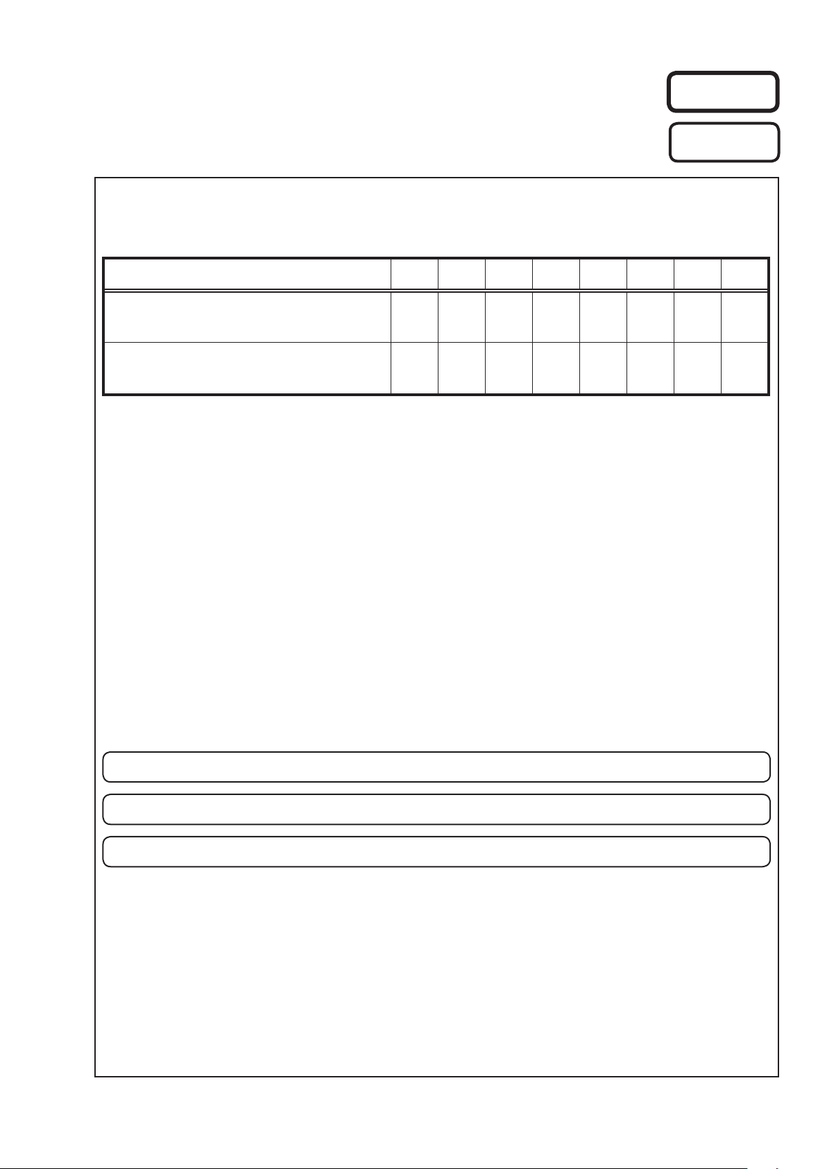
Maximum external dimensions :
435 (W) x 167 (H) x 382 (D) mm
Weight : 11.8 kg
DIMENSION
245
22
382
338.5
29.88635.2
435
340
21.5
151
167
16
236.8
54.7
5
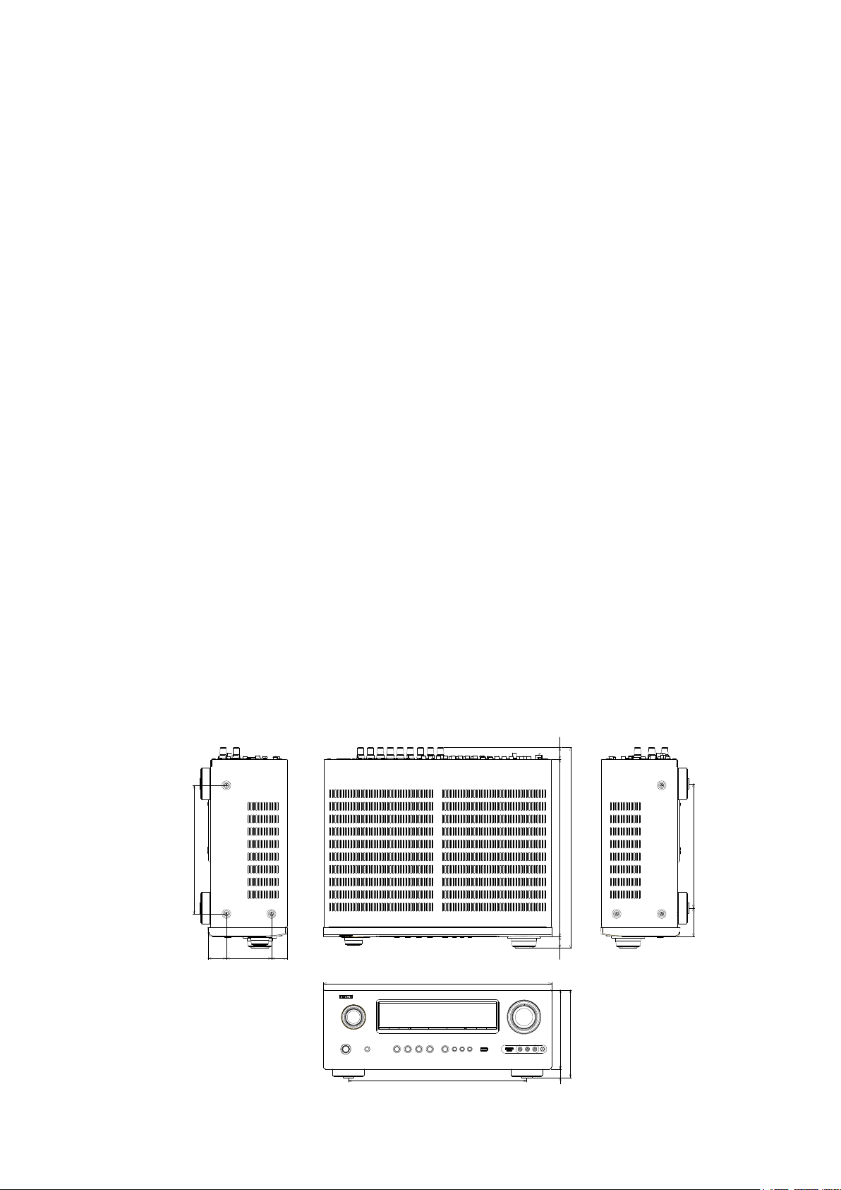
CAUTIONS IN SERVICING
Initializing INTEGRATED NETWORK AV RECEIVER
INTEGRATED NETWORK AV RECEIVER initialization should be performed when the μcom, peripheral parts of μcom,
and Digital P.W.B. were replaced.
1. Turn off the power pressing ON/STANDBY button.
2. Press ON/STANDBY button while simultaneously while pressing PRESET CHANNEL 2 and PRESET CHANNEL 3
buttons.
3. Check that the entire display is ashing at intervals of about 1 second, and then release the 2 buttons.
The microprocessor will be initialized.
Note: • If step 3 fails, start over from step 1.
• All user settings will be lost and the factory setting will be recovered after the set is initialized.
So make sure to note down your setting beforehand for restoring after the initialization.
ON/STANDBY
PRESET CHANNEL 3
PRESET CHANNEL 2
Service Jig
When you repair the printing board, you can use the following JIG (Extension cable kit).
Please order it from Denon Ofcial Service Distributor in your region if necessary.
8U-110084S
(Refer to 63 page.)
d
: EXTENSION UNIT KIT : 1 Set
6

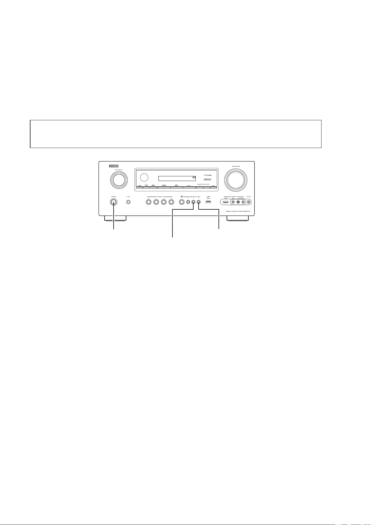
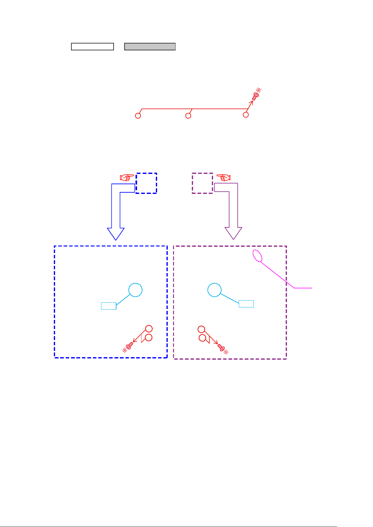
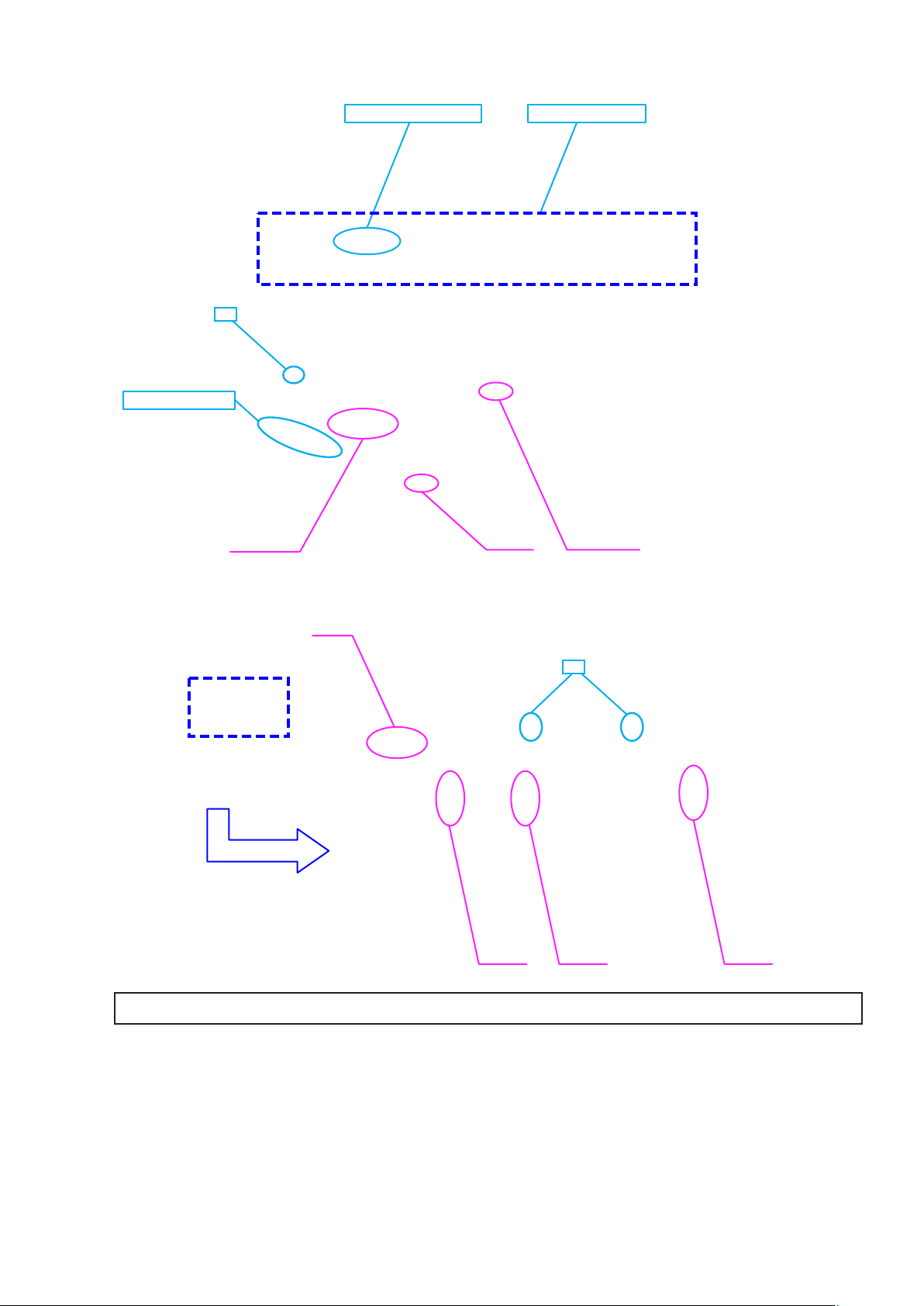
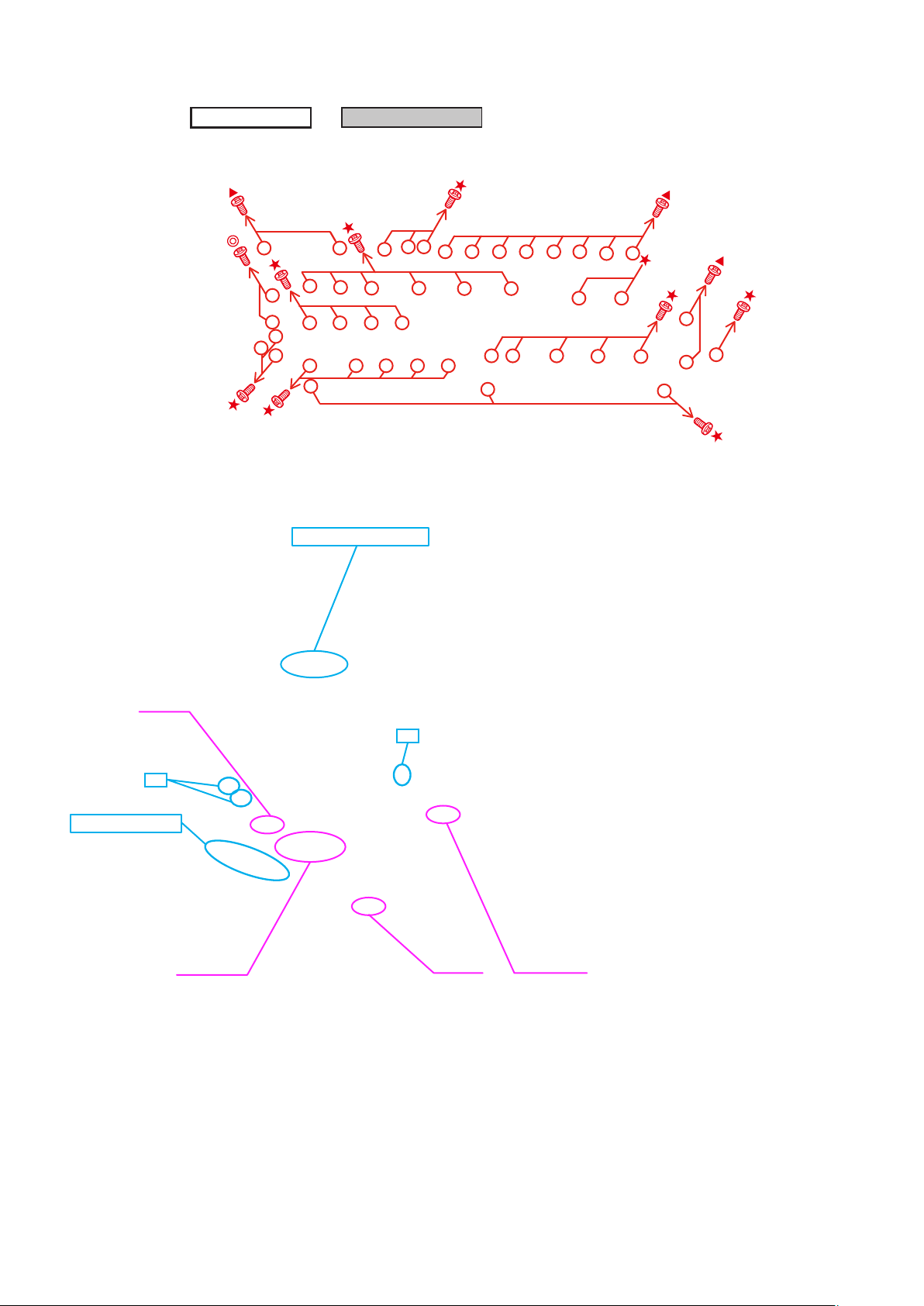
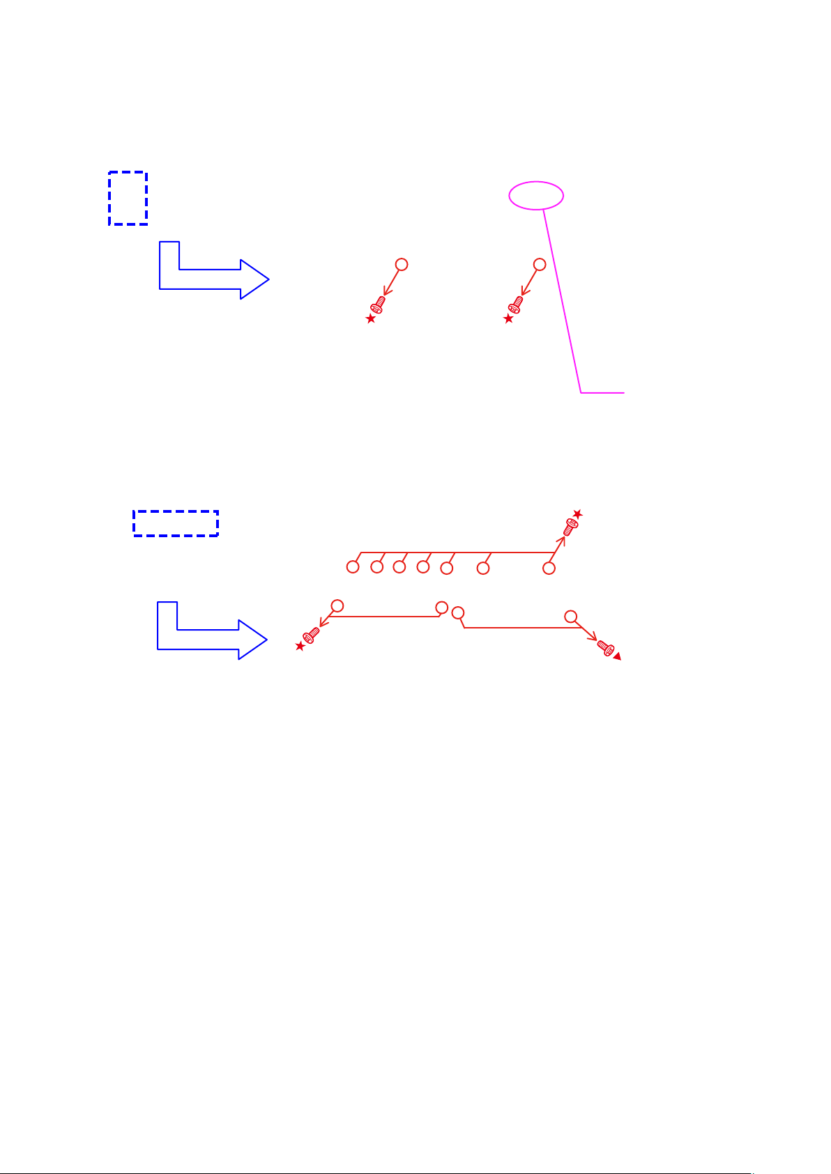
DISASSEMBLY
• Disassemble in order of the arrow in the following gure.
• In the case of the re-assembling, assemble it in order of the reverse of the following ow.
• In the case of the re-assembling, observe "attention of assembling".
• If wire bundles are untied or moved to perform adjustment or replace parts etc., be sure to rearrange them neatly as
they were originally bundled or placed afterward.
Otherwise, incorrect arrangement can be a cause of noise generation.
CABINET TOP
FRONT PANEL ASSY
Refer to "DISASSEMBLY
1. FRONT PANEL ASSY"
and "EXPLODED VIEW"
PCB V.AUX_VOL
(Ref. No. of EXPLODED VIEW : C1)
PCB HP
(Ref. No. of EXPLODED VIEW : C2)
PCB USB
(Ref. No. of EXPLODED VIEW : C3)
PCB FRONT
(Ref. No. of EXPLODED VIEW : C4)
PCB SELECTOR
(Ref. No. of EXPLODED VIEW : C5)
PCB HDMI FFC GUIDE
(Ref. No. of EXPLODED VIEW : C6)
PCB FRONT HDMI
(Ref. No. of EXPLODED VIEW : C25)
HEAT SINK ASSY
Refer to "DISASSEMBLY
2. HEAT SINK ASSY"
and "EXPLODED VIEW"
PCB GUIDE R
(Ref. No. of EXPLODED VIEW : C7)
PCB GUIDE L
(Ref. No. of EXPLODED VIEW : C8)
PCB GUIDE TOP
(Ref. No. of EXPLODED VIEW : C9)
PCB 7CH_AMP ASSY
(Ref. No. of EXPLODED VIEW : C10)
HDMI UNIT ASSY
Refer to "DISASSEMBLY
3. HDMI UNIT ASSY"
and "EXPLODED VIEW"
PCB FRONT CNT
(Ref. No. of EXPLODED VIEW : C11)
PCB SIDE CNT
(Ref. No. of EXPLODED VIEW : C12)
PCB RS232C
(Ref. No. of EXPLODED VIEW : C13)
PCB SPK_PREOUT
(Ref. No. of EXPLODED VIEW : C14)
PCB RS232C CNT
(Ref. No. of EXPLODED VIEW : C15)
PCB FUSE
(Ref. No. of EXPLODED VIEW : C16)
PCB F_WIDE
(Ref. No. of EXPLODED VIEW : C17)
PCB INPUT
(Ref. No. of EXPLODED VIEW : C18)
PCB VIDEO ASSY
(Ref. No. of EXPLODED VIEW : C20)
PCB HDMI
(Ref. No. of EXPLODED VIEW : C22)
POWER TRANS
Refer to "DISASSEMBLY
4. POWER TRANS"
and "EXPLODED VIEW"
POWER TRANS
(Ref. No. of EXPLODED VIEW : C23)
7

About the photos used for "descriptions of the DISASSEMBLY" section
• The shooting direction of each photograph used herein is indicated on the left side of the respective photograph as
"Shooting direction: ***".
• Refer to the diagram below about the shooting direction of each photograph.
• Photographs with no shooting direction indicated were taken from the top of the set.
• The photograph is AVR-3312CIE3 model.
The viewpoint of each photograph
(Shooting direction)
Shooting direction: B
[View from the top]
Front side
Shooting direction: DShooting direction: C
Shooting direction: A
8
1. FRONT P ANEL ASSY
Proceeding :
(1) Remove the screws.
View from the bottom
CABINET TOP
FRONT PANEL ASSY
→
(2) Cut the wire clamp band, then disconnect the connector wires and FFC cables. Remove the screws.
STYLE PIN : Loosen
cut
CN602
TAPE : Remove
cut
FFC cable
Please refer to "EXPLODED VIEW" for the disassembly method of each P.W.B included in FRONT PANEL ASSY.
9
CN390 FFC cable
2. HEAT SINK ASSY
Proceeding :
(1) Remove the screws.
CABINET TOP
View from the bottom
(2) Cut the wire clamp band, then remove the screws. Disconnect the connector wires.
HEAT SINK ASSY
→
Shooting direction: C
cut
Shooting direction: D
CN602
cut
10
(3) Cut the wire clamp band, then disconnect the connector wire and FFC cables .
STYLE PIN : Loosen HEAT SINK Assy
cut
TAPE : Remove
FFC cable
CN390 FFC cable
(4) Cut the wire clamp bands, then disconnect the connector wires.
CN461
cut
CN702CN703CN701
Please refer to "EXPLODED VIEW" for the disassembly method of each P.W.B included in HEAT SINK ASSY.
11
3. HDMI UNIT ASSY
Proceeding :
(1) Remove the screws, then remove the BACK PANEL and the HDMI BRACKET.
Shooting of photograph: A
(2) Cut the wire clamp band, then disconnect the connector wires and the FFC cables.
Remove the PCB DOCK from the PCB SIDE CNT and PCB RS232C(Board to board).
CABINET TOP
STYLE PIN : Loosen
HDMI UNIT ASSY
→
CN704
cut
TAPE : Remove
FFC cable
cut
CN390 FFC cable
12
(3) Disconnect the connector wire. Remove the screws.
(4) Remove the screws.
CN931
13
(5) Cut the wire clamp band, then disconnect the connector wires.
cut
CN940CN932CN941 CN903 CN781
(6) Cut the wire clamp band, then disconnect the connector wires.
cut
CN461
CN701
CN703 CN702
14
(7) Cut the wire clamp bands, then disconnect the connector wires, and remove the screws.
cut
cut
CN203 CN902
(8) Remove the screw.
Please refer to "EXPLODED VIEW" for the disassembly method of each P.W.B included in HDMI UNIT ASSY.
4. TRANS MAIN
Proceeding :
Please refer to "EXPLODED VIEW" for the disassembly method of each P.W.B included in TRANS MAIN.
CABINET TOP
HDMI UNIT ASSY
→
15
POWER TRANS
→
SPECIAL MODE
d
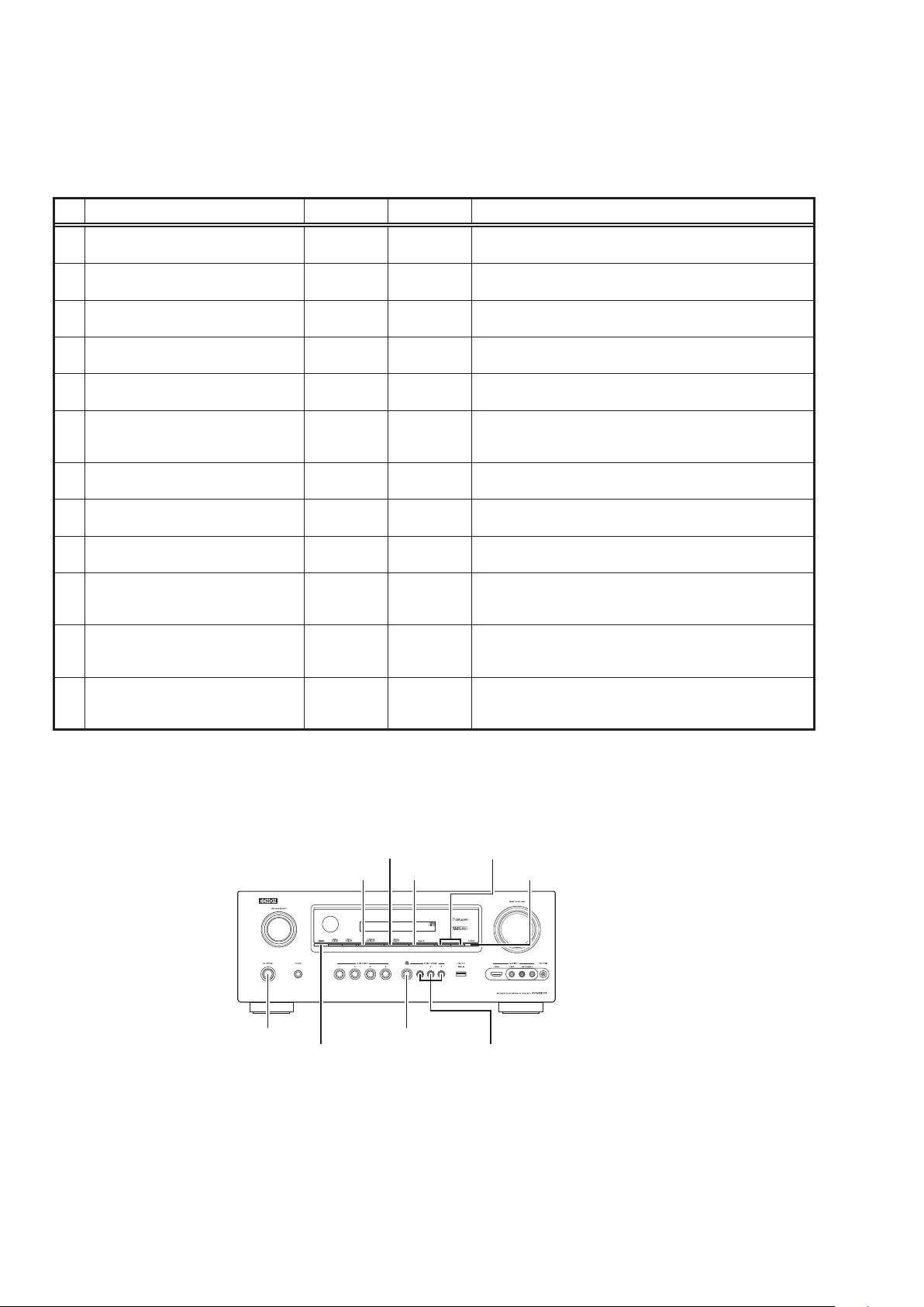
Special mode setting button
No.1 - 10, 12 : Press the ON/STANDBY button to turn on the power while pressing both the button A and the button B at the same
b
No.11 : Press and hold both buttons A and B for over 3 second with the power turned on.
b
No. Mode Button A Button B Contents
Version display
1
(μcom/DSP Error Display)
2 Displaying the protection history mode
IInitialization mode
3
(Remove settings for Installer Setup.)
IInitialization mode
4
(Includes settings for Installer Setup.)
Mode for switching tuner frequency step
5
(E2 model Only)
Mode for preventing remote control
6
acceptance
7 Panel lock mode
Panel lock mode
8
(Master volume is not locked.)
9 Cancellation of panel lock mode
10 Diagnostic mode
11 Remote ID Setup mode
12 Installer Setup mode
NOTE:
If " REC " is displayed on the uorescent display, the set is in the special developer's mode and the RS-232C
communications are not possible.
Turn on the power, then press and hold down the "PRESET CHANNEL 2" and " STATUS " buttons for over 3 seconds to
turn off "Q" on the display. RS-232C communications are now enabled.
time.
TUNER
PRESET CH +
TUNER
PRESET CH -
PRESET
CHANNEL 2
PRESET
CHANNEL 1
ZONE3
SELECT
PRESET
CHANNEL 1
PRESET
CHANNEL 2
PRESET
CHANNEL 2
TUNER
PRESET CH -
PRESET
CHANNEL 1
PRESET
CHANNEL 1
ZONE2/REC
SELECT
STATUS
STATUS
PRESET
CHANNEL 3
PRESET
CHANNEL 2
iPod
INTERNET
RADIO
iPod
TUNER
PRESET CH -
DIMMER Panel lock mode is cancelled.
STATUS
STATUS
STATUS
Firmware versions such as Main or DSP are displayed in the FL
manager. Errors are displayed when they occur. (Refer to 17 page)
The protection history is displayed.
(Refer to 20 page)
Backup data initialization is carried out.
(Remove settings for Installer Setup.)
Backup data initialization is carried out.
(Includes settings for Installer Setup.)
Change tuner frequency step to FM:200kHz/AM:10kHzSTEP
1
Operations using the remote control are rejected.
(Mode cancellation: Turn off the power and execute the same
button operations as when performing setup.)
Operations using the main unit panel buttons or the master volume
1
knob are rejected.
Operations using the main unit panel buttons are rejected.
This mode is used for conrming the Video and Audio (signal)
paths. (Troubleshooting)
The signal paths of the set can be easily conrmed after repair.
When using multiple DENON AV receivers in the same room, make
this setting so that only the desired AV receiver operates.(Refer to 22
page)
Access the Remote Maintenance mode via the internet.Installer
Setup is displayed on GUI/Option Menu.
Refer to AVR_RemoteMaintenance_.pdf of SDI.
b
ZONE3 SELECT
ZONE2/REC SELECT
ON/STANDBY
DIMMER PRESET CHANNEL 1,2,3
TUNER PRESET CH +,-
iPod 1
INTERNET RADIO
16
STATUS
1. µcom/DSP Version display mode
1.1. Operationspecications
µcom/DSP version display mode:
When the set is started up in this mode, the version information is displayed.
Starting up:
Press the "ON/STANDBY" button to turn on the power while pressing the "STATUS" and "PRESET CH +" buttons.
Now, press the "STATUS" button to the display the 2nd item information on the FL Display.
When the version is displayed on the FL Display, the version list is also displayed on the OSD.
b
1.2. Display Order
Error information(Refer to 1.3. Error display) →
→ e Main µ-com/MAIN FBL(1st Boot Loader) Version → r Sub µ-com/Sub FBL → t DSP version →
→ u GUI SFLASH →
→ o Ethernet(DM860) 2nd Boot Loader, Rhapsody Flag →
→ Q1 Ethernet(DM860)MAC ADDRESS information →
→
MultEQ Pro APP(Displayed when Audyssey Pro is complete)
Q3
→ Q4 MultEQ Pro ICL(Displayed when Audyssey Pro is complete
Model destination information :
q
Upper
A V R 3 3 1 2 E 3 : * * * *
Lower
S / N . * * * * * * * * * *
Ethernet(DM860) 1st Boot Loader, Hardware ID
i
Model destination information →
q
Ethernet(DM860) IMAGE
Q0
HD RADIO SDK/HD RADIO BBP(AVR-3312CIE3 only)
Q2
Firmware Package Version
w
Audio PLD
y
Firmware Package Version :
w
Upper
Lower
Main µ-com & MAIN FBL version :
e
Upper
Lower
Sub µ-com & Sub FBL :
r
Upper
Lower
DSP ROM :
t
Upper
Lower
Audio PLD :
y
Upper
Lower
F i r m . P a c k a g e
M a i n : * * . * *
M a i n F B L : * * . * *
S u b : * * . * *
S u b F B L : * * . * *
D S P : * * . * *
A u d i o P L D : * * . * *
V e r . : * * * *
GUI SFLASH :
u
Upper
Lower
G U I : * * * * * * * *
17
Ethernet(DM860) 1st Boot Loader, Hardware ID :
i
Upper
Lower
Ethernet(DM860) 2nd Boot Loader, Rhapsody Flag :
o
Upper
Lower
Ethernet(DM860) IMAGE :
Q0
Upper
Lower
Ethernet(DM860)MAC ADDRESS information :
Q1
Upper
Lower
HD RADIO SDK/HD RADIO BBP (AVR-3312CIE3 onlly) :
Q2
Upper
Lower
E t h e r n e t F B L
* * * * * * - A A
E t h e r n e t S B L
* * * * * * * * * * * * * - B B
E t h e r n e t I M G
* * * * * * * * * * * * *
* E t h e r n e t M A C
* * * * * * - * * * * * *
* M u l t E Q P r o A P P
* * . * * . * * . * * * *
MultEQ Pro APP :
Q3
Upper
* M u l t E Q P r o A P P
Lower
* * . * * . * * . * * * *
MultEQ Pro ICL :
Q4
Upper
* M u l t E Q P r o I C L
Lower
* * . * * . * * . * * * *
18

1.3. Error display
s
See the following table for each "Error information" display and its explanation (status).
Display order is
Condition Status FL Display Trouble shooting
q
Firm Check
NG
w
GUI Version
NG
e
SUB NG
r
DIR NG
t
DSP NG
y
IP SCALER
NG
u
E2PROM NG
i
Both DSP /
EEPROM OK
q,w,e,r,t,y,u,i
Compared with the destination setting
on the board. This is displayed when the
model name or destination information
written into the rmware does not match.
(b1)
Error occurs in GUI version and Main
μ-com version.(
No response from SUB microcomputer.
No response from DIR
When DSP code boot is performed, the
DSP FLAG0 port does not change to "H"
even if DSP reset is executed.
Before DSP command is issued, the DSP
BUSY port does not change to "L".
When DSP data read is performed,
executing WRITE="L" does not result in
ACK="H".
When DSP data read is performed,
executing REQ="L" does not result in
ACK="L".
When DSP data writing is performed,
executing WRITE="H" does not result in
ACK="H".
When DSP data writing is performed,
executing REQ="L" does not result in
ACK="L".
An error has occurred in the i/p Scaler
(ADV8002)initial settings. The error is a
DDR memory Loopback Test error.
Error occurs in E2PROM checksum.(*** is
a block address number.)
2)
b
.
• Please check the
destination-resistors
R2060/R2061, HDMI
(
F I R M E R R O R
G U I V E R . E R R O R
S U B E R R O R 0 1
D I R E R R O R 0 1
B'D).
• Please write the
rmware of correct
destination.
• Please check the
rmware of correct
version.
• Please check SUB
(IC231) and arroud
circuits.
• Please check DIR
IC403/IC404/IC405,
(
HDMI B'D) and around
circuits.
D S P E R R O R 0 1
D S P E R R O R 0 2
D S P E R R O R 0 3
• Please check DSP
IC408, HDMI B'D)
(
D S P E R R O R 0 4
and around circuits.
D S P E R R O R 0 5
D S P E R R O R 0 6
• Please check
I P S C A L E R E R R 0 1
ADV8002 (IC151) and
arroud circuits.
E 2 P R O M E R R * * *
(No error display, version display only)
Status FL Display
1,
2
b
b
The written Firmware and product settings
(model name, brand name, destination) are
compared. If Firmware that is not designed
for this product is written, ▲ is displayed in
the rst column, as shown on the right.
–
M a i n : * * . * *
–
S U B : * * . * *
–
D S P : * * . * *
–
A u d i o P L D : * * . * *
–
G U I : * * * * * * * *
19
2. Errors checking mode (Displaying the protection history)
2.1. Operationspecications
Error mode (Displaying the protection history):
When the set is started up in this mode, the error information is displayed.
Starting up:
•Commoninallthemodels
Press the "ON/STANDBY" button to turn on the power while pressing the "STATUS" and "TUNER PRESET-" buttons.
The error (protection history display) mode is set.
Now, press the "STATUS" button to turn on the FL display.
2.2. About the display on the FL display
When the "STATUS" button is pressed after setting the error (protection history display) mode is set, a history like the one
shown below is displayed, depending on the conditions.
(1) Normal (when there has been no protection incident)
Upper
P R O T E C T H I S T O R Y
Lower
: N O P R O T E C T
(2) For ASO (when the last protection incident was ASO protection)
Upper
P R O T E C T H I S T O R Y
Lower
: A S O
Cause: The line between speaker terminals is shorted, or speakers with impedance of less than the rated value.
Supplementary information: As the excess current is detected after operation of the speaker relay, a short on the
speaker terminal and the connected speaker can be identied.
If the power is turned on without correcting the abnormality, the protection function will work about 5 seconds later
and the power supply will be shut off.
(3) For DC (when the last protection incident was DC protection)
Upper
P R O T E C T H I S T O R Y
Lower
: D C
Cause: DC output of the power amplier is abnormal.
If the power is turned on without correcting the abnormality, the protection function will work about 5 seconds later
and the power supply will be shut off.
(4) For THERMAL (when the last protection incident was THERMAL protection)
Upper
P R O T E C T H I S T O R Y
Lower
: T H E R M A L *
: A~D
z
Cause: The temperature of the heat sink is excessive.
If the power is turned on without correcting the abnormality, the protection function will work about 5 seconds later
and the power supply will be shut off.
Additional causes of protection can be due to loose connections, associated components, Microprocessor, etc.
b
When the "STATUS" button is pressed again after the above protection history as shown above is displayed, the normal
display reappears.(Refer to "PROTECTION DIAGRAM" 23 page.)
20
2.3. Clearing the protection history
There are two ways to clear the protection history, as described below.
(1) Start up the set in error (protection display) mode and display the error, then press and hold down the "INTERNET
RADIO" button for 3 seconds.
Upper
P R O T E C T H I S T O R Y
Lower
: T H E R M A L A
Press the "INTERNET RADIO" button for 3 seconds.
Upper
P R O T E C T H I S T O R Y
Lower
Upper
P R O T E C T H I S T O R Y
Lower
: N O P R O T E C T
(2) Initialize. (Refer to "Initializing INTEGRATED NETWORK AV RECEIVER" 6 page.)
If you want to save a backup, perform the method in 2.3.(1) above.
b
C L E A R
The above is displayed and the protection history is cleared.
Warning indication by the POWER LED
If the power is turned off when a protection incident has been detected, the POWER LED (red) ashes as a warning
according to the conditions in which the protection incident occurred.
(1) ASO/DC PROTECTION : Flashes at intervals of 0.5 seconds (0.25 seconds lit, 0.25 seconds off)
(2) THERMAL (A/B/C/D) PROTECTION : Flashes at intervals of 2 seconds (1 second lit, 1 second off)
21
3. Remote ID Setup mode
3.1. Specications
When using multiple DENON AV receivers in the same room, make this setting so that only the desired AV receiver
operates.
2.2. Setting the AV receivers
Starting up:
Press and hold both "STATUS" and "PRESET 1" buttons for over 3 second with the power turned on.
(1) When Remote ID Setup mode is started, the following is displayed.
Upper
Lower
(2) Press the "QUICK SELECT 1 - 4" button that corresponds to the number you want to set.
Button FL Display
QUICK SELECT 1
QUICK SELECT 2
QUICK SELECT 3
QUICK SELECT 4
(3) Turn off the power using "ON/STANDBY" button.
(4) Turn on the power using "ON/STANDBY" button.
When Remote ID Setup mode is running, operations other than the "QUICK SELECT 1 - 4" buttons or "ON/
b
STANDBY" buttons on the main unit are not received.
R E M O T E I D ?
R E M O T E I D 1
R E M O T E I D 2
R E M O T E I D 3
R E M O T E I D 4
2.2. Setting the Remote control unit
(1) Press and hold both "ZONE/DEVICE (1)" button for at least 3 second.
The zone mode indicator ashes twice.
(2) Press the "AMP" button.
The zone mode indicator ashes twice.
(3) Press the "1, 2, 3 or 4" button.
The zone mode indicator ashes twice.
NOTE:
If the IDs do not match, "AVAMPz" (
control unit is operated.
is the main unit's remote control ID) appears on the display when the remote
z
22
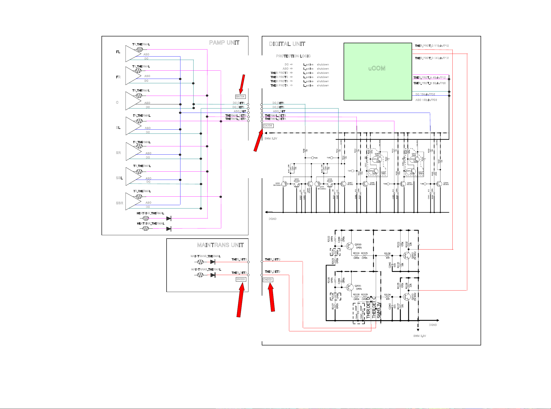
PROTECTION DIAGRAM
AVR3312/2312/SR6006 PROTECTION DIAGRAM
2011_5_26 D&M P1 D.Hara
d
TR_THERMAL
FL
FR
C
SL
SR
SBL
ASO
DC
TR_THERMAL
ASO
DC
TR_THERMAL
ASO
DC
TR_THERMAL
ASO
DC
TR_THERMAL
ASO
DC
TR_THERMAL
ASO
DC
PAMP UNIT
DC_DET4
DC_DET3
ASO_DET
THERMAL_DETB
THERMAL_DETA
BN704
DIGITAL UNIT
PROTECTION LOGIC
DC ⇒ L_active shutdown
ASO ⇒ L_active shutdown
THER PROTD ⇒ L_active shutdown
THER PROTC ⇒ L_active shutdown
THER PROTB ⇒ L_active shutdown
THER PROTA ⇒ L_active shutdown
DC_DET4
DC_DET3
ASO_DET
THERMAL_DETB
THERMAL_DETA
CN704
SWM 3.3V
THER_PROT_C 115pin/P12
THER_PROT_D 141pin/P12
uCOM
THER_PROT_A 45pin/P12
THER_PROT_B 50pin/P56
DC 124pin/PD2
ASO 123pin/PD3
SBR
TR_THERMAL
ASO
DC
HEATSINK_THERMAL
HEATSINK_THERMAL
MAINTRANS UNIT
MAINTRANS_THERMAL
MAINTRANS_THERMAL
THER_DETC
THER_DETD
BN203
DGND
THER_DETC
THER_DETD
CN203
DGND
23
SWM 3.3V
4. DIAGNOSTICMODE(Video/Audio(signal)pathconrmationmode)
d
This mode is used for conrming the Video and Audio (signal) paths. (Troubleshooting)
Conrming the operation of unit can be easily done after repair.
Backup data will not be lost.
4.1. Starting diagnostic mode
Press the "PRESET CHANNEL 1" and "STATUS" button while simultaneously pressing those two buttons of this unit.
Q1, Q2 and Q3 are lit in FL display.
4.2. Canceling diagnostic mode
Turn off the power by pressing the ON/Standby button.
4.3. Operation
When you perform remote operation in accordance with the instructions in "Details of how to operate remote controller" *a) in the table below using the remote control unit (RC-1156).
You will nd using another remote control unit with the macro functions very useful. To use the macro functions, program a macro function to output a remote control code in accordance with the steps in *b) in the table below.
4.4. Videosystemconrmationitems
g.XX : Refer to the block diagram of the g.XXth.
Conrmation item Setting and display
Analog Video (signal) Path Video Convert (IP Scaler) : OFF , All Sources
All ZONE : ON
Display:
V 0 1 D V D
1
g.1
Analog Video Convert (signal) Path Video Convert(IP Scaler) : ON , All Sources
Display:
V 0 2 D V D
2
g.2
HDMI (signal) Path Video Convert(IP Scaler) : OFF, All Sources
All ZONE:ON
Display:
V 0 1 D V D
3
g.3
Details of how to operate remote controller *a)
1.Press [AMP]
2.Press [ZONE SELECT] , Select "ZONE2"
3.Press [ZONE OFF]
4.Press [ZONE SELECT], Select "ZONE3"
5.Press [ZONE OFF]
6.Press [ZONE SELECT], Select "MAIN"
7.Press [1/./]
8.Press [ZONE SELECT], Select "ZONE2"
9.Press [ZONE ON]
10.Press [ZONE SELECT], Select "ZONE3"
11.Press [ZONE ON]
12.Press [ZONE SELECT], Select "MAIN"
13.Press [DVD]
1.Press [AMP]
2.Press [ZONE SELECT] , Select "ZONE2"
3.Press [ZONE OFF]
4.Press [ZONE SELECT], Select "ZONE3"
5.Press [ZONE OFF]
6.Press [ZONE SELECT], Select "MAIN"
7.Press [2/ABC]
8.Press [DVD]
1.Press [AMP]
2.Press [ZONE SELECT] , Select "ZONE2"
3.Press [ZONE OFF]
4.Press [ZONE SELECT], Select "ZONE3"
5.Press [ZONE OFF]
6.Press [ZONE SELECT], Select "MAIN"
7.Press [1/./]
8.Press [ZONE SELECT], Select "ZONE2"
9.Press [ZONE ON]
10.Press [ZONE SELECT], Select "ZONE3"
11.Press [ZONE ON]
12.Press [ZONE SELECT], Select "MAIN"
13.Press [DVD]
Output sequence of remote control codes
It is useful to form a macro program. *b)
※
ZONE2 POWER OFF ·Input : CVBS / Output : CVBS
q
·Input : CVBS / Output : CVBS RECOUT (DVR)
·Input : CVBS / Output : CVBS ZONE2
ZONE3 POWER OFF
w
KEY 1/CODE1 (Main Zone)
e
Initialization & Video Convert All OFF
ZONE2 POWER ON
r
ZONE3 POWER ON
t
DVD (Main Zone)
y
ZONE2 POWER OFF ·Input : CVBS / Through : V.Decoder and V.Encoder / Output : CVBS
q
ZONE3 POWER OFF
w
KEY 2/ABC (Main Zone)
e
Initialization & Video Convert All ON & IP
Scaler "Analog & HDMI"
DVD (Main Zone)
r
ZONE2 POWER OFF ·Input : HDMI / Output : HDMI
q
ZONE3 POWER OFF
w
KEY1/CODE1 (Main Zone)
e
Initialization & Video Convert All OFF
ZONE2 POWER ON
r
ZONE3 POWER ON
t
DVD (Main Zone)
y
·Input : S-Video / Output : CVBS
·Input : Component / Output : Component
(
As the input source, you can switch from DVD to other ones.)
※
· Input : CVBS / Through : V.Decoder and V.Encoder / Output :
Component
·Input : S-Video / Through V.Decoder and V.Encoder / Output : CVBS
· Input : S-Video / Through V.Decoder and V.Encoder / Output :
Component
·Input : Component / Through V.Decoder and V.Encoder / Output : CVBS
· Input : Component / Through V.Decoder and V.Encoder / Output :
Component
(
As the input source, you can switch from DVD to other ones.)
※
(
As the input source, you can switch from DVD to other ones.)
※
Contents of conrmation Remarks
only AVR3312
Conrm the input pass one by one.
Because it becomes only the input of the highest input
becomes Convert/IP Scaler (signal) Path if it inputs it at
the same time.
(HDMI input > Component input > S-VIDEO input >
CVBS input)
Do not connect anything with HDMI Monitor OUT.
Because the Convert pass is used with Analog to HDMI
when connecting it.
24
Conrmation item Setting and display
Analog or HDMI to HDMI (signal) Path
4
g.4
OSD FUNCTION Video Convert(IP Scaler) : ON, All Sources
Video Convert(IP Scaler) : ON, All Sources
IP Scaler : Analog & HDMI , All Sources
Resolution : "AUTO", All Sources
Display:
V 0 2 D V D
IP Scaler : Analog & HDMI , All Sources
Resolution : "AUTO", All Sources
Menu : ON
All ZONE :ON
Display:
V 0 2 D V D
5
g.5
CEC FUNCTION
(Control Monitor : HDMI Monitor1)
6
CEC FUNCTION
(Control Monitor : HDMI Monitor 2)
7
HDMI Audio (signal) Path
(Audio : AMP)
8
HDMI Audio (signal) Path
(Audio : TV)
9
g.6
g.7
g.8
g.9
HDMI Control : ON
Control Monitor Monitor1 (When checking the
HDMI Monitor Out1)
Display:
V 0 3 D V D
HDMI Control : ON
Control Monitor Monitor 2 (When checking the
HDMI Monitor Out 2)
Display:
V 0 4 D V D
Audio : AMP(When checking the audio output
from AMP)
Display:
V 0 5 D V D
Audio : TV(When checking the audio output
from TV)
Display:
V 0 6 D V D
Details of how to operate remote controller *a)
1.Press [AMP]
2.Press [ZONE SELECT] , Select "ZONE2"
3.Press [ZONE OFF]
4.Press [ZONE SELECT], Select "ZONE3"
5.Press [ZONE OFF]
6.Press [ZONE SELECT], Select "MAIN"
7.Press [2/ABC]
8.Press [DVD]
1.Press [AMP]
2.Press [ZONE SELECT] , Select "ZONE2"
3.Press [ZONE OFF]
4.Press [ZONE SELECT], Select "ZONE3"
5.Press [ZONE OFF]
6.Press [ZONE SELECT], Select "MAIN"
7.Press [2/ABC]
8.Press [ZONE SELECT], Select "ZONE2"
9.Press [ZONE ON]
10.Press [ZONE SELECT], Select "ZONE3"
11.Press [ZONE ON]
12.Press [ZONE SELECT], Select "MAIN"
13.Press [DVD]
14.Press [AMP]
15.Press [MENU]
1.Press [AMP]
2.Press [ZONE SELECT] , Select "ZONE2"
3.Press [ZONE OFF]
4.Press [ZONE SELECT], Select "ZONE3"
5.Press [ZONE OFF]
6.Press [ZONE SELECT], Select "MAIN"
7.Press [3/DEF]
8.Press [DVD]
1.Press [AMP]
2.Press [ZONE SELECT] , Select "ZONE2"
3.Press [ZONE OFF]
4.Press [ZONE SELECT], Select "ZONE3"
5.Press [ZONE OFF]
6.Press [ZONE SELECT], Select "MAIN"
7.Press [4/GHI]
8.Press [DVD]
1.Press [AMP]
2.Press [ZONE SELECT], Select "ZONE2"
3.Press [ZONE OFF]
4.Press [ZONE SELECT], Select "ZONE3"
5.Press [ZONE OFF]
6.Press [ZONE SELECT], Select "MAIN"
7.Press [5/JKL]
8.Press [DVD]
1.Press [AMP]
2.Press [ZONE SELECT] , Select "ZONE2"
3.Press [ZONE OFF]
4.Press [ZONE SELECT], Select "ZONE3"
5.Press [ZONE OFF]
6.Press [ZONE SELECT], Select "MAIN"
7.Press [6/MNO]
8.Press [DVD]
Output sequence of remote control codes
It is useful to form a macro program. *b)
※
ZONE2 POWER OFF ·Input CVBS / Through : IP Scaler / Output : HDMI
q
·Input S-VIDEO / Through : IP Scaler / Output : HDMI
·Input Component / Through : IP Scaler / Output : HDMI
ZONE3 POWER OFF
w
KEY 2/ABC (Main Zone)
e
Initialization & Video Convert All ON & IP
Scaler "Analog & HDMI"
DVD (Main Zone)
r
ZONE2 POWER OFF ·OSD Display / Output : CVBS
q
ZONE3 POWER OFF
w
KEY 2/ABC (Main Zone)
e
Initialization &VideoConvert All ON & IP
Scaler"Analog&HDMI"
ZONE2 POWER ON
r
ZONE3 POWER ON
t
DVD (Main Zone)
y
GUI MENU (Main Zone)
u
ZONE2 POWER OFF
q
ZONE3 POWER OFF
w
KEY 3/DEF (Main Zone)
e
Initialization & CEC Control ON & Select
Control Monitor 1
DVD (Main Zone)
r
ZONE2 POWER OFF When the power supply of a TV is put in the standby mode, make sure
q
ZONE3 POWER OFF
w
KEY 4/GHI (Main Zone)
e
Initialization & CEC Control ON & Select
Control Monitor 2
DVD (Main Zone)
r
ZONE2 POWER OFF ·Input : HDMI (Signal of PCM, DolbyDigital or DTS) / Output : Speakers
q
ZONE3 POWER OFF
w
KEY 5/JKL (Main Zone)
e
Initialization & Select Audio AMP
DVD (Main Zone)
r
ZONE2 POWER OFF
q
ZONE3 POWER OFF
w
KEY 6/MNO (Main Zone)
e
Initialization & Audio Select TV
DVD (Main Zone)
r
·Input HDMI / Through : IP Scaler / Output : HDMI
(
As the input source, you can switch from DVD to other ones.)
※
·OSD Display / Output : Component
·OSD Display / Output : HDMI
(
As the input source, you can switch from DVD to other ones.)
※
· When the power supply of a TV is put in the standby mode, make sure
that the power supply of this unit is also put in the standby mode.
(
As the input source, you can switch from DVD to other ones.)
※
that the power supply of this unit is also put in the standby mode.
(
As the input source, you can switch from DVD to other ones.)
※
·Input : HDMI (Signal of HD Audio) / Output : Speakers
(
As the input source, you can switch from DVD to other ones.)
※
· Input : HDMI (Signal of PCM or DolbyDigital or DTS) / Output : HDMI
(Audio output from connected TV)
(
As the input source, you can switch from DVD to other ones.)
※
Contents of conrmation Remarks
Conrm the input pass one by one.
Because it becomes only the input of the highest input
becomes Convert/IP Scaler (signal) Path if it inputs it at
the same time.
(HDMI input > Component input > S-VIDEO input >
CVBS input)
Connect HDMI Monitor OUT / Output : OSD from HDMI
No connect HDMI Monitor OUT / Output : OSD from
Component
No output other terminal.
AVR2312/3312 are nothing ZONE2 OSD
※
only AVR3312
25
3.5. Audiosystemconrmationitems
g.XX : Refer to the block diagram of the g.XXth.
Conrmation item Setting and display
Analog (signal) Path Input Mode : Fixed ANALOG
SURROUND mode : DIRECT
Amp assign : NORMAL
Display:
1
A 0 1 D V D
g.10
DIGITAL (signal) Path
(MAIN)
Input Mode : Fixed DIGITAL
Amp assign : NORMAL
Display:
A 0 2 D V D
2
g.11
DIGITAL (signal) Path
(ZONE2)
Input Mode : Fixed DIGITAL
Amp assign : ZONE2
ZONE2 Function : Source
Display:
A 0 3 D V D
3
g.12
DIGITAL (signal) Path
(ZONE3)
Input Mode : Fixed DIGITAL
Amp assign : ZONE3
ZONE3 Function : Source
Display:
A 0 4 D V D
4
g.13
HDMI (signal) Path Input Mode : Fixed HDMI
Amp assign : NORMAL
Display:
A 0 5 D V D
5
g.14
Details of how to operate remote controller
1.Press [AMP]
2.Press [ZONE SELECT] , Select "ZONE2"
3.Press [ZONE OFF]
4.Press [ZONE SELECT], Select "ZONE3"
5.Press [ZONE OFF]
6.Press [ZONE SELECT], Select "MAIN"
7.Press [7/PQRS]
8.Press [DVD]
1.Press [AMP]
2.Press [ZONE SELECT] , Select "ZONE2"
3.Press [ZONE OFF]
4.Press [ZONE SELECT], Select "ZONE3"
5.Press [ZONE OFF]
6.Press [ZONE SELECT], Select "MAIN"
7.Press [8/TUV]
8.Press [DVD]
1.Press [AMP]
2.Press [ZONE SELECT] , Select "ZONE2"
3.Press [ZONE OFF]
4.Press [ZONE SELECT], Select "ZONE3"
5.Press [ZONE OFF]
6.Press [ZONE SELECT], Select "MAIN"
7.Press [9/WXYZ]
8.Press [ZONE SELECT], Select "ZONE2"
9.Press [ZONE ON]
10.Press [ZONE SELECT], Select "MAIN"
11.Press [DVD]
1.Press [AMP]
2.Press [ZONE SELECT] , Select "ZONE2"
3.Press [ZONE OFF]
4.Press [ZONE SELECT], Select "ZONE3"
5.Press [ZONE OFF]
6.Press [ZONE SELECT], Select "MAIN"
7.Press [0/_*]
8.Press [ZONE SELECT], Select "ZONE3"
9.Press [ZONE ON]
10.Press [ZONE SELECT], Select "MAIN"
11.Press [DVD]
1.Press [AMP]
2.Press [ZONE SELECT] , Select "ZONE2"
3.Press [ZONE OFF]
4.Press [ZONE SELECT], Select "ZONE3"
5.Press [ZONE OFF]
6.Press [ZONE SELECT], Select "MAIN"
7.Press [MOVIE]
8.Press [DVD]
Output sequence of remote control codes
It is useful to form a macro program.
※
ZONE2 POWER OFF ·Input : Analog / Output : Speakers (Front L/R)
q
·Input : Analog / Output : Pre OUT(Front L/R)
(
As the input source, you can switch from DVD to other ones.)
※
ZONE3 POWER OFF
w
KEY 7/PQRS (Main Zone)
e
Initialization & Amp assign NORMAL& Input
Mode Fixed ANALOG & SURROUND mode
DIRECT
DVD (Main Zone)
r
ZONE2 POWER OFF ·Input : Digital / Output : Speakers (Front L/R)
q
·Input : Digital / Output : Pre OUT(Front L/R)
(
As the input source, you can switch from DVD to other ones.)
※
ZONE3 POWER OFF
w
KEY 8/TUV (Main Zone)
e
Initialization & Amp assign NORMAL& Input
Mode Fixed DIGITAL
DVD (Main Zone)
r
ZONE2 POWER OFF ·Input : Digital / Output : Speakers (SURR BACK L/R)
q
·Input : Digital / Output : Pre OUT(ZONE2 L/R)
(
As the input source, you can switch from DVD to other ones.)
※
ZONE3 POWER OFF
w
KEY9/WXYZ (Main Zone)
e
Initialization & Amp assign ZONE2 & Input
Mode Fixed DIGITAL
ZONE2 POWER ON
r
DVD (Main Zone)
t
ZONE2 POWER OFF ·Input : Digital / Output : Speakers (SURR BACK L/R)
q
·Input : Digital / Output : Pre OUT(ZONE3 L/R)
(
As the input source, you can switch from DVD to other ones.)
※
ZONE3 POWER OFF
w
KEY 0/CODE2 (Main Zone)
e
Initialization & Amp assign ZONE3 & Input
Mode Fixed DIGITAL
ZONE3 POWER ON
r
DVD (Main Zone)
t
ZONE2 POWER OFF ·Input : HDMI / Output : Speakers (Front L/R)
q
·Input : HDMI / Output : Pre OUT(Front L/R)
(
As the input source, you can switch from DVD to other ones.)
※
ZONE3 POWER OFF
w
MOVIE
e
Initialization &Amp assign NORMAL & Input
Mode Fixed HDMI
DVD (Main Zone)
r
Contents of conrmation Remarks
AVR2312: Only "NET/USB" corresponds to the input
source.
only AVR3312
26
Conrmation item Setting and display
A/D (signal) Path
(Main Zone)
6
g.15
Amp Assign (signal) Path
(Amp Assign : ZONE2)
7
g.16
Amp Assign (signal) Path
(Amp Assign : ZONE3)
8
Amp Assign (signal) Path
(Amp Assign : ZONE2/ZONE3-MONO)
9
g.17
g.18
Amp assign : NORMAL
SURROUND mode : Multi ch STEREO
Vol -20dB
Speaker Cong : SSSSY
(Front/Center/Surround/SourroundBack : Small, SW : Yes)
Display:
A 0 6 D V D
Amp assign : ZONE2
ZONE2 Function : Source
Zone2 Vol -20dB
Display:
A 0 7 D V D
Amp assign : ZONE3
SURROUND mode : Multi ch STEREO
Zone3 Vol -20dB
Display:
A 0 8 D V D
Amp assign : ZONE2/ZONE3-MONO
SURROUND mode : Multi ch STEREO
ZONE2 Vol -20dB
ZONE3 Vol -20dB
Display:
A 0 9 D V D
Details of how to operate remote controller
1.Press [AMP]
2.Press [ZONE SELECT] , Select "ZONE2"
3.Press [ZONE OFF]
4.Press [ZONE SELECT], Select "ZONE3"
5.Press [ZONE OFF]
6.Press [ZONE SELECT], Select "MAIN"
7.Press [MUSIC]
8.Press [DVD]
1.Press [AMP]
2.Press [ZONE SELECT] , Select "ZONE2"
3.Press [ZONE OFF]
4.Press [ZONE SELECT], Select "ZONE3"
5.Press [ZONE OFF]
6.Press [ZONE SELECT], Select "MAIN"
7.Press [GAME]
8.Press [ZONE SELECT], Select "ZONE2"
9.Press [ZONE ON]
10.Press [ZONE SELECT], Select "MAIN"
11.Press [DVD]
1.Press [AMP]
2.Press [ZONE SELECT] , Select "ZONE2"
3.Press [ZONE OFF]
4.Press [ZONE SELECT], Select "ZONE3"
5.Press [ZONE OFF]
6.Press [ZONE SELECT], Select "MAIN"
7.Press [DIRECT]
8.Press [ZONE SELECT], Select "ZONE3"
9.Press [ZONE ON]
10.Press [ZONE SELECT], Select "MAIN"
11.Press [DVD]
1.Press [AMP]
2.Press [ZONE SELECT] , Select "ZONE2"
3.Press [ZONE OFF]
4.Press [ZONE SELECT], Select "ZONE3"
5.Press [ZONE OFF]
6.Press [ZONE SELECT], Select "MAIN"
7.Press [6]
8.Press [ZONE SELECT], Select "ZONE2"
9.Press [ZONE ON]
10.Press [ZONE SELECT], Select "ZONE3"
11.Press [ZONE ON]
12.Press [ZONE SELECT], Select "MAIN"
13.Press [DVD]
Output sequence of remote control codes
It is useful to form a macro program.
※
ZONE2 POWER OFF ·Input : Analog / Output : Speakers (Front L/R)
q
·Input : Analog / Output : Pre OUT(Front L/R), SW(20Hz)
(
As the input source, you can switch from DVD to other ones.)
※
ZONE3 POWER OFF
w
MUSIC
e
Initialization &Amp assign NORMAL &
SURROUND mode : Multi ch STEREO &
Volume -20dB
DVD (Main Zone)
r
ZONE2 POWER OFF ·Input : Analog / Output : Speakers (SURR BACK L/R)
q
·Input : Analog / Output : Pre OUT (ZONE2 L/R)
(
As the input source, you can switch from DVD to other ones.)
※
ZONE3 POWER OFF
w
GAME
e
Initialization & Amp assign ZONE2 &
SURROUND mode : Multi ch STEREO &
ZONE2 Volume -20dB
ZONE2 POWER ON
r
DVD (Main Zone)
t
ZONE2 POWER OFF ·Input : Analog / Output : Speakers (SURR BACK L/R)
q
·Input : Analog / Output : Pre OUT (ZONE3 L/R)
(
As the input source, you can switch from DVD to other ones.)
※
ZONE3 POWER OFF
w
DIRECT
e
Initialization & Amp assign ZONE3 &
SURROUND mode : Multi ch STEREO &
ZONE3 Volume -20dB
ZONE3 POWER ON
r
DVD (Main Zone)
t
ZONE2 POWER OFF ·Input : Analog / Output : Speakers (SURR BACK L/R)
q
·Input : Analog / Output : Pre OUT (ZONE2 L/R)
·Input : Analog / Output : Pre OUT (ZONE3 L/R)
ZONE3 POWER OFF
w
e
6
Initialization & Amp assign ZONE2/ZONE3MONO & SURROUND mode : Multi ch
STEREO & ZONE2 Volume -20dB &
ZONE3 Volume -20dB
ZONE2 POWER ON
r
ZONE3 POWER ON
t
DVD (Main Zone)
y
(
As the input source, you can switch from DVD to other ones.)
※
Contents of conrmation Remarks
only AVR3312
only AVR3312
27

Conrmation item Setting and display
Amp Assign (signal) Path
(Amp Assign : 2CH)
10
Amp assign : 2CH
SURROUND mode : DIRECT
Vol -20dB
Display:
A 1 0 D V D
g.19
Amp Assign (signal) Path
(Amp Assign : BiAMP)
11
Amp assign : BiAMP
SURROUND mode : Multi ch STEREO
Vol -20dB
Display:
A 1 1 D V D
g.20
Amp Assign (signal) Path
(Amp Assign : Front-B)
12
Amp assign : Front-B
SURROUND mode : Multi ch STEREO
Vol -20dB
Display:
A 1 2 D V D
g.20
Front Height (signal) Path Amp assign : Front Height ( As AVR2312)
Amp assign : NORMAL (As AVR3312)
SURROUND mode : Multi ch STEREO
Vol -20dB
Surround Parameter-Speaker : F.Height
Display:
A 1 4 D V D
13
g.22
Front Wide (signal) Path Amp assign : NORMAL
SURROUND mode : Multi ch STEREO
Vol -20dB
Surround Parameter-Speaker : F.Wide
14
g.23
Display:
A 1 5 D V D
Details of how to operate remote controller
1.Press [AMP]
2.Press [ZONE SELECT] , Select "ZONE2"
3.Press [ZONE OFF]
4.Press [ZONE SELECT], Select "ZONE3"
5.Press [ZONE OFF]
6.Press [ZONE SELECT], Select "MAIN"
7.Press [7]
8.Press [DVD]
1.Press [AMP]
2.Press [ZONE SELECT] , Select "ZONE2"
3.Press [ZONE OFF]
4.Press [ZONE SELECT], Select "ZONE3"
5.Press [ZONE OFF]
6.Press [ZONE SELECT], Select "MAIN"
7.Press [8]
8.Press [DVD]
1.Press [AMP]
2.Press [ZONE SELECT] , Select "ZONE2"
3.Press [ZONE OFF]
4.Press [ZONE SELECT], Select "ZONE3"
5.Press [ZONE OFF]
6.Press [ZONE SELECT], Select "MAIN"
7.Press [9]
8.Press [DVD]
1.Press [AMP]
2.Press [ZONE SELECT] , Select "ZONE2"
3.Press [ZONE OFF]
4.Press [ZONE SELECT], Select "ZONE3"
5.Press [ZONE OFF]
6.Press [ZONE SELECT], Select "MAIN"
7.Press [+10/MEMORY]
8.Press [DVD]
1.Press [AMP]
2.Press [ZONE SELECT], Select "ZONE2"
3.Press [ZONE OFF]
4.Press [ZONE SELECT], Select "ZONE3"
5.Press [ZONE OFF]
6.Press [ZONE SELECT], Select "MAIN"
7.Press [SLEEP]
8.Press [DVD]
Output sequence of remote control codes
It is useful to form a macro program.
※
ZONE2 POWER OFF ·Input : Analog / Output : Speakers (SURR BACK L/R)
q
·Input : Analog / Output : Pre OUT (Front L/R)
(
As the input source, you can switch from DVD to other ones.)
※
ZONE3 POWER OFF
w
e
7
Initialization &Amp assign 2CH &
SURROUND mode : DIRECT & Volume
-20dB
DVD (Main Zone)
r
ZONE2 POWER OFF ·Input : Analog / Output : Speakers (SURR BACK L/R)
q
·Input : Analog / Output : Pre OUT (SB L/R)
(
As the input source, you can switch from DVD to other ones.)
※
ZONE3 POWER OFF
w
e
8
Initialization & Amp assign BiAMP &
SURROUND mode : Multi ch STEREO &
Volume -20dB
DVD (Main Zone)
r
ZONE2 POWER OFF ·Input : Analog / Output : Speakers (SURR BACK L/R)
q
·Input : Analog / Output : Pre OUT (SB L/R)
(
As the input source, you can switch from DVD to other ones.)
※
ZONE3 POWER OFF
w
e
9
Initialization & Amp assign Front-B &
SURROUND mode Multi ch STEREO &
Volume -20dB
DVD (Main Zone)
r
ZONE2 POWER OFF ·Input : Analog / Output : Speakers (F.HEIGHT L/R)
q
(
As the input source, you can switch from DVD to other ones.)
※
ZONE3 POWER OFF
w
MEMORY/+10 (Main Zone)
e
As AVR2312
Initialization & Amp assign Front Height &
SURROUND mode:Multi ch STEREO &
Volume -20dB
As AVR3312
Initialization & Amp assign NORMAL &
SURROUND mode:Multi ch STEREO &
Volume -20dB & Surround Parameter-
Speaker : F.Height
DVD (Main Zone)
r
ZONE2 POWER OFF ·Input : Analog / Output : Speakers (F.WIDE L/R)
q
(
As the input source, you can switch from DVD to other ones.)
※
ZONE3 POWER OFF
w
SLEEP MODE
e
Initialization &Amp assign NORMAL &
SURROUND mode:Multi ch STEREO &
Volume -20dB Surround Parameter-Speaker
: F.Wide
DVD (Main Zone)
r
Contents of conrmation Remarks
AVR2312 and AVR3312, operate differently
only AVR3312
28
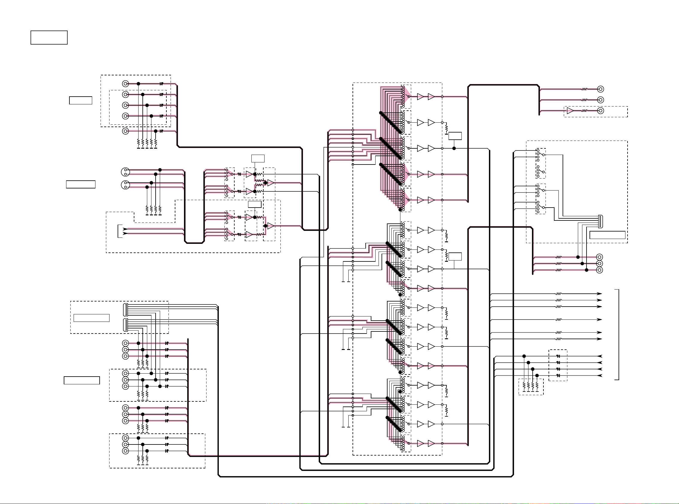
BLOCK DIAGRAM
g.1
d
AVR3312/2312 VIDEO BLOCK
CVBS IN
S-VIDEO IN
AVR3312
DVD
DVR
SAT
AVR2312
V.AUX(FRONT)
iPod
DVR
AVR3312
IC551
BD
BD_V
DVD_V
DVR_V
SAT_V
IN1
IN2
IN3
IN4
IN5
IN6
IN7
IN8
IN9
ETHER_SY
ETHER_SC
V.AUX_V
75
DETECT
F
IC554
BD7628F
IC555
BD7628F
CIRCUIT
DETECT
CIRCUIT
IC556
BD7628F
75
75
DEC_SY_IN
MAIN Y/C
DEC_SC_IN
ZONE2 Y/C
IC552
BU4052BC
IC553
75
BU4052BCF
BD_V
DVD_V
SAT_V
DVR_V
VDO_CVBS
V.AUX_V
MAIN Y/C
ZONE2 Y/C
AVDM-2000
6dB
MONITOR
Z2 MONITOR
VOUT4
1k
VOUT5
1k
DETECT
CIRCUIT
MONITOR
REC
DEC_CVBS_IN
VIN2L1
VIN1L1
VIN2L2
VIN1L2
VIN2L3
VIN1L3
VOUT1
75
VOUT2
75
VOUT3
75
REC
Z2 MONITOR
BU4052BCF
MONIL1
BU4052BCF
MONIL2
MONIL3
MONITOR
REC
Z2 MONITOR
AVR3312
ONLY JPN AVR3312
D VIDEO OUT
YOUT3
1k
JAPAN D-JACK
JAPAN D-JACK
COMPONENT IN
TO DIGITAL AUDIO BLOCK
DVD
BD
OPEN
SAT
DVD_Y
DVD_CB
DVD_CR
BD_Y
BD_CB
BD_CR
SAT_Y
SAT_CB
SAT_CR
VIN1L1
VIN1L2
VIN1L3
VIN2L1
VIN2L2
VIN2L3
VDO_CVBS
VDO_Y
VDO_PB
VDO_PR
BD_Y
DVD_Y
SAT_Y
BD_PB
DVD_PB
SAT_PB
BD_PR
DVD_PR
SAT_PR
YIN1
YIN2
YIN3
YIN4
YIN5
YIN6
PBIN1
PBIN2
PBIN3
PBIN4
PBIN5
PBIN6
PRIN1
PRIN2
PRIN3
PRIN4
PRIN5
PRIN6
1k
75
75
1k
1k
75
75
1k
1k
75
YOUT4
YOUT1
YOUT2
PBOUT3
PBOUT4
PBOUT1
PBOUT2
PROUT3
PROUT4
PROUT1
DETECT
CIRCUIT
ZONE1 PB
ZONE1 Y
DEC_Y_IN
DEC_PB_IN
DEC_PR_IN
DEC_Y_IN
DEC_PB_IN
DEC_PR_IN
DEC_CVBS_IN
DEC_SY_IN
DEC_SC_IN
VDO_Y
VDO_PB
VDO_PR
VDO_CVBS
AVR2312
ZONE1 Y
ZONE1 PB
ZONE1 PR
0
COMPONENT OUT
TO HDMI BLOCK
AVR3312
DVR
OPEN
DVR_Y
DVR_CB
DVR_CR
29
75
PROUT2
ZONE1 PR
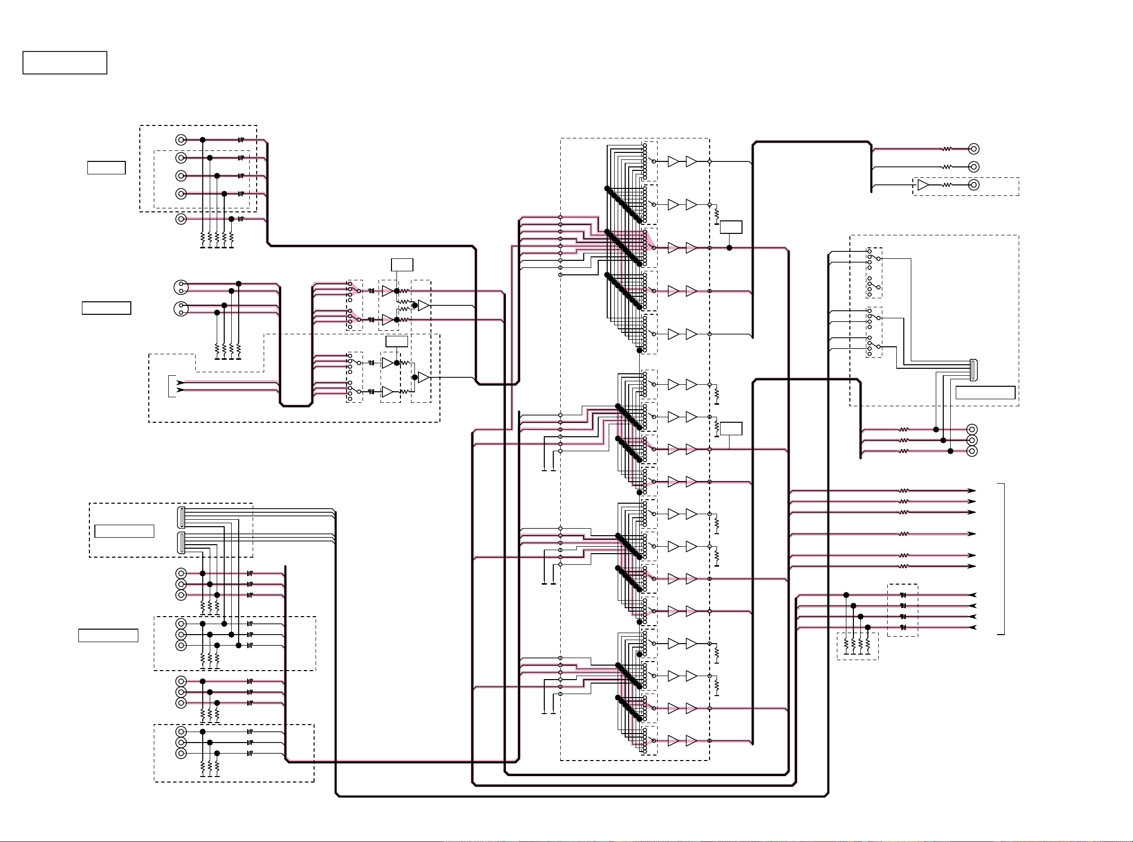
g.2(1/2)
AVR3312/2312 VIDEO BLOCK
CVBS IN
S-VIDEO IN
AVR3312
DVD
DVR
SAT
AVR2312
V.AUX(FRONT)
iPod
DVR
AVR3312
IC551
BD
BD_V
DVD_V
DVR_V
SAT_V
IN1
IN2
IN3
IN4
IN5
IN6
IN7
IN8
IN9
ETHER_SY
ETHER_SC
V.AUX_V
75
DETECT
IC554
BD7628F
IC555
BD7628F
CIRCUIT
DETECT
CIRCUIT
IC556
BD7628F
75
75
DEC_SY_IN
MAIN Y/C
DEC_SC_IN
ZONE2 Y/C
IC552
BU4052BC
F
IC553
75
BU4052BCF
BD_V
DVD_V
SAT_V
DVR_V
VDO_CVBS
V.AUX_V
MAIN Y/C
ZONE2 Y/C
AVDM-2000
6dB
MONITOR
VOUT4
1k
VOUT5
1k
VOUT1
75
VOUT2
75
VOUT3
75
Z2 MONITOR
DETECT
CIRCUIT
MONITOR
REC
DEC_CVBS_IN
VIN2L1
VIN1L1
VIN2L2
VIN1L2
VIN2L3
VIN1L3
REC
Z2 MONITOR
BU4052BCF
MONIL1
BU4052BCF
MONIL2
MONIL3
MONITOR
REC
Z2 MONITOR
AVR3312
ONLY JPN AVR3312
D VIDEO OUT
YOUT3
1k
JAPAN D-JACK
JAPAN D-JACK
COMPONENT IN
TO DIGITAL AUDIO BLOCK
DVD
BD
OPEN
SAT
DVD_Y
DVD_CB
DVD_CR
BD_Y
BD_CB
BD_CR
SAT_Y
SAT_CB
SAT_CR
VIN1L1
VIN1L2
VIN1L3
VIN2L1
VIN2L2
VIN2L3
VDO_CVBS
VDO_Y
VDO_PB
VDO_PR
BD_Y
DVD_Y
SAT_Y
BD_PB
DVD_PB
SAT_PB
BD_PR
DVD_PR
SAT_PR
YIN1
YIN2
YIN3
YIN4
YIN5
YIN6
PBIN1
PBIN2
PBIN3
PBIN4
PBIN5
PBIN6
PRIN1
PRIN2
PRIN3
PRIN4
PRIN5
PRIN6
1k
75
75
1k
1k
75
75
1k
1k
75
YOUT4
YOUT1
YOUT2
PBOUT3
PBOUT4
PBOUT1
PBOUT2
PROUT3
PROUT4
PROUT1
DETECT
CIRCUIT
ZONE1 PB
ZONE1 Y
DEC_Y_IN
DEC_PB_IN
DEC_PR_IN
DEC_Y_IN
DEC_PB_IN
DEC_PR_IN
DEC_CVBS_IN
DEC_SY_IN
DEC_SC_IN
VDO_Y
VDO_PB
VDO_PR
VDO_CVBS
AVR2312
ZONE1 Y
ZONE1 PB
ZONE1 PR
0
COMPONENT OUT
TO HDMI BLOCK
AVR3312
DVR
OPEN
DVR_Y
DVR_CB
DVR_CR
30
75
PROUT2
ZONE1 PR
 Loading...