

Page 1
jpM:;: I '
' I :^: : v : T:
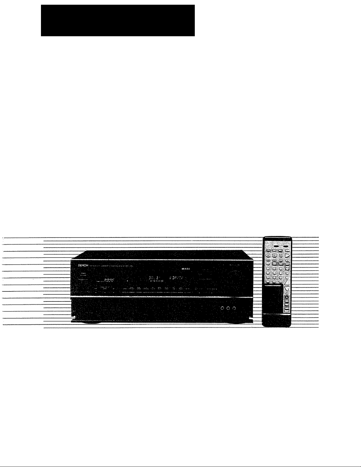
AV SURROUND RECEIVER
AVR-2500
OPERATING INSTRUCTIONS
The photograph shows the AVR-2500 (black),
(without side wood boards)
Manufactured under license from Dolby Laboratories Licensing Corporation. Additionally
licensed under Canadian patent number 1,037,877. "Dolby," "Pro Logic," and the
doub!e-D symbol are trademarks of Dolby Laboratories Licensing Corporation.
S We greatly appreciate your purchase of the AVR-2500.
H To be sure you take maximum advantage of all the features the AVR-2500 has to offer, read these instructions
carefully and use the set properly. Be sure to keep this manual for future reference should any questions or
problems arise.
'SERIAL NO.
PLEASE RECORD UNIT SERIAL NUMBER ATTACHED TO THE REAR OF THE
CABINET FOR FUTURE REFERENCE"
Page 2
m
Remote Control Unit
3'1 System code buttons
3-2 Preset memory
3- 3 Remote control unit learning function ..
Operations
B
4- 1 Preparations for playback
4-2 Playing the program source
{stereo play back}
4-3 Adjusting the BALANCE control and
TONE control.................................................
4-4 Simulcast play back.........................................
4-5 Using the muting function................................
4-6 Listen with headphones...................................
4-7 Multi-Source recording/playback
4-8 Using the surround function
.......................................
................................................
...............................
.........................................
.....................
............................
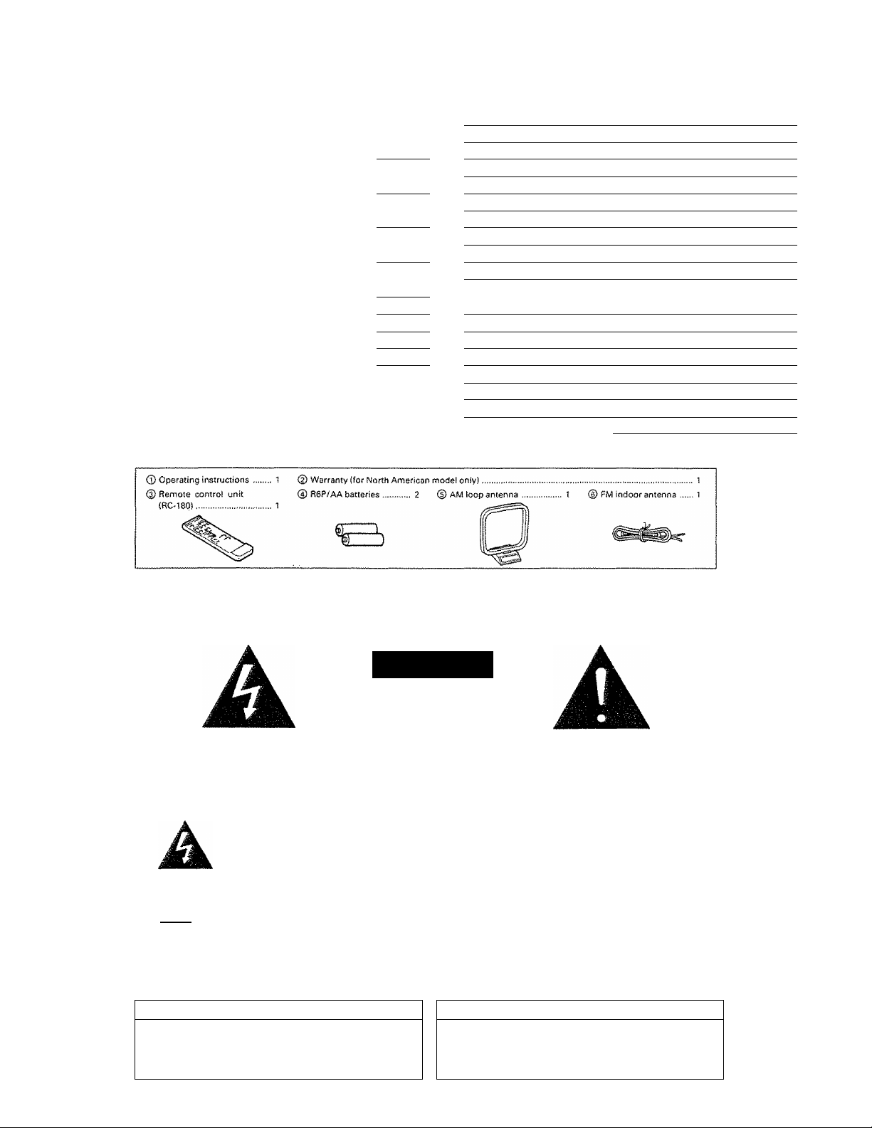
♦ ACCESSORIES
Check that the following parts are included in addition to the main unit:
TABLE OF CONTENTS
.. 2-4
.. 5-8
......
10,11
....
12
....
13
....
13
....
14
....
14
....
14
....
14
....
15
15-17/
9
Listening to the radio
B
5-1 Auto preset memory
5-2 Auto tuning
5-3 Manual tuning
5-4 Preset memory
5-5 ^^Becaiiing'preset stations
5-6 RDS (Radio Data System)
5-7 ROS search
5-8 PTY search..............................................................
5-9 TP search
5-10 RT (Radio Text)
Easy Operation Functions
6-1 On screen display....................................................
6-2 Front panel display
6-3 Persona! memory
6-4 System call (Remote control unit)............................................ 22
Initialization of the Microprocessor
0
Last function memory
a
Troubleshooting
B
Specifications.................................................................
1!
................................................
..............................................................
..........................................................
........................................................
....................................
......................................
............................................................
................................................................
.....................................................
.................................................
....................................................
..............................
....................................................
............................................................
................
................
................
................
................
................
................
................
................
................
................
18
18
18
19
20
22
22
22
23
23
24
\
MJ INTRODUCTION
SAFETY PRECATIONS
Él
WARNING: TO REDUCE THE RISK OF FIRE OR ELECTRIC SHOCK, DO NOT EXPOSE THIS
CAUTION
RISK OF ELECTRIC SHOCK
DO NOT OPEN
CAUTION; TO REDUCE THE RISK OF ELECTRIC SHOCK,
DO NOT REMOVE COVER (OR BACK). NO USER SERVICE
ABLE PARTS INSIDE. REFER SERVICING TO QUALIFIED
SERVICE PERSONNEL
The lightning flash with arrowhead symboL within an equilateral triangle,
is intended to alert the user to the presence of uninsulated "dangerous
voltage" within the product's enclosure that may be of sufficient
magnitude to constitute a risk of electric shock to persons.
The exclamation point within an equilateral triangle is intended to alert the
user to the presence of important operating and maintenance (servicing}
instructions in the literature accompanying the appliance.
APPLIANCE TO RAIN OR MOISTURE.
CAUTION ATTENTION
TO PREVENT ELECTRIC SHOCK DO NOT USE THIS (POLA
RIZED) PLUG WITH AN EXTENSION CORO, RECEPTACLE OR
OTHER OUTLET UNLESS THE SLADES CAN 3E FULLY IN
SERTED TO PREVENT SLADE EXPOSURE.
POUR PREVENIR LES CHOCS ELECTRIOUES NE PAS UTILISER
CETTE FICHE POLARISEE AVEC UN PROLONGATEUR UNE
PRISE OE COURANT OU UNE AUTRE SORTIE DE COURANT,
SAUF SI LES LAMES PEUVENT ETRE INSEREES A FOND SANS
EN LAISSER AUCUNE PARTIE A DECOUVERT.
Page 3
SAFETY INSTRUCTIONS
1. Read Instructions - All the safety and operating
instructions should be read before the appliance Is
operated,
2. Retain Instructions The safety and operating
instructions should be retained for future reference.
3. Heed Warnings - All warnings on the appliance and
in the operating instructions should be adhered to.
4. Follow instructions ™ All operating and use instruc
tions should be followed,
5. Water and Moisture - The appliance should not be
used near water -- for example, near a bathtub,
washbowl, kitchen sink, laundry tub, in a wet
basement, or near a swimming pool, and the like.
6. Carts and Stands ~ The appliance should be used
only with a cart or stand that is recommended by the
manufacturer.
6A. An appliance and
cart combination
should be moved
with care. Quick
stops, excessive
force, and uneven
surfaces may cause
the appliance and cart combination to overturn.
7. Wall or Ceiling Mounting - The appliance should be
mounted to a wall or ceiling only as recommended
by the manufacturer.
8. Ventilation ™ The appliance should be situated so
that its location or position does not interfere with Its
proper ventilation. For example, the appliance
should not be situated on a bed, sofa, rug, or similar
surface that may block the ventilation openings; or,
placed in a buiit-ln installation, such as a bookcase or
cabinet that may impede the flow of air through the
ventilation openings.
9. Heat - The appliance should be situated away from
heat sources such as radiators, heat registers,
stoves, or other appliances (including amplifiers)
that produce heat.
10. Power Sources “The appliance should be connected
to a power supply only of the type described in the
operating instructions or as marked on the ap
pliance.
11, Grounding or Polarization - Precautions should be
taken so that the grounding or polarization means of
an appliance is not defeated.
12. Power-Cord Protection - Power-supply cords should
be routed so that they are not likely to be walked on
or pinched by items placed upon or against them,
paying particular attention to cords at plugs, con
venience receptacles, and the point where they exit
from the appliance.
14. Cleaning - The appliance should be cleaned only as
recommended by the manufacturer.
15. Power Lines - An outdoor antenna should be located
away from power lines,
16. Outdoor Antenna Grounding - If an outside antenna
is connected to the receiver, be sure the antenna
system is grounded so as to provide some protec
tion against voltage surges and built-up static
charges. Article 810 of the National Electrical Code,
ANSI/NFPA 70, provides information with regard to
proper grounding of the mast and supporting struc
ture, grounding of the lead-in wire to an antennadischarge unit, size of grounding conductors, loca
tion of antenna-discharge unit, connection to
grounding electrodes, and requirements for the
grounding electrode, See Figure A.
17. Nonuse Periods - The power cord of the appliance
should be unplugged from the outlet when left
unused for a long period of time.
18. Object and Liquid Entry - Care should be taken so
that objects do not fall and liquids are not spilled into
the enclosure through openings.
19. Damage Requiring Service - The appliance should
be serviced by qualified service personnel when:
A. The power-supply cord or the plug has been
damaged; or
B. Objects have fallen, or liquid has been spilled into
the appliance; or
C. The appliance has been exposed to rain; or
D. The appliance does not appearto operate normal
ly or exhibits a marked change in performance; or
E. The appliance has been dropped, or the enclosure
damaged.
20. Servicing ~ The user should not attempt to service
the appliance beyond that described in the operating
instructions. All other servicing should be referred to
qualified service personnel.
Page 4
* NOTE ON USE
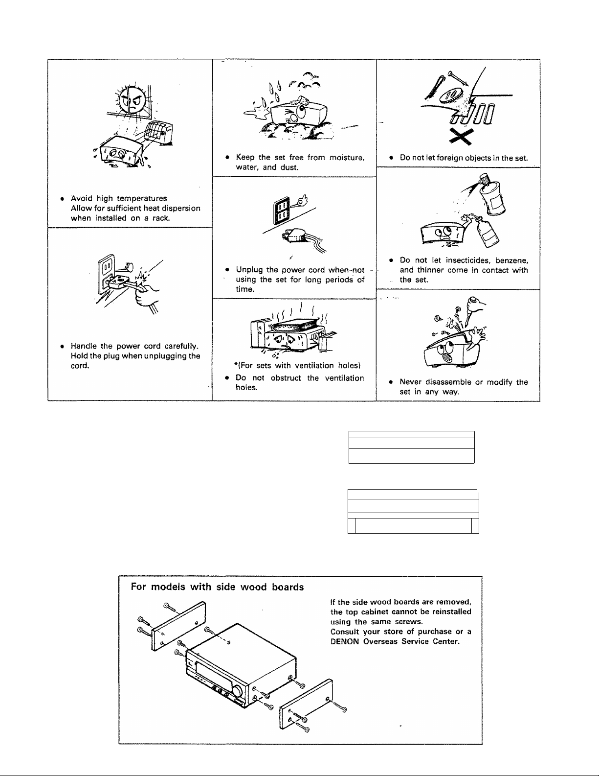
• INSTALLATION PRECAUTIONS
Using this receiver or other electronic equipment containing
microprocessors simultaneously with a tuner or TV may result in
noise in the sound or picture.
If this should happen, take the following steps:
• Install the receiver as far as possible from the tuner or TV set.
• Keep the antenna lines of the tuner or TV as far as possible
from the receiver's power cord and connection cables.
• This problem is especially frequent when using indoor anten
nas. We recommend using outdoor antennas and 75 Q/ohms
coaxial cables.
A note on stacking
f" 1 m
—
..................
y ocjoociao ^ ^
For cooling purposes, do not place another AV component directly on
top of the receiver. Be sure to leave a space of at least 10 cm.
..........
__
¡1 1
-------
ii'.TfrriTTTjl OOO
® as L]
10 cm or greater
aaa j)
0 o
o®©o
CO Player
JL
AVR-2500
(This receiver)
Page 5
2 CONNECTIONS
Do not plug in the power cord until all connections have
been completed.
Be sure to connect the left and right channels properly (left
with left, right with right}.
Insert the plugs securely. Incomplete connections will
result in the generation of noise.
Use the AC OUTLETS for audio equipment only. Do not use
them for hair driers, etc.
2-1 Connecting the audio components
Center speaker
NOTE:
The receiver cannot be used with
MC cartridges directiy. Use a
separate head amplifier or stepup transformer,
Turntable (MM cartridge)
A B
Note that binding pin plug cords together with power cords
or placing them near a power transformer will result in the
introduction of hum or other noise.
If hum or other noise is produced when the ground wire is
connected, disconnect it.
Noise or humming may be generated if a connected
component is used independently without turning the
power of the AVR-2500 on, If this happens, turn on the
power of the AVR'2500,
* Precautions when connecting speakers
If a speaker is placed near a TV or video monitor, the colors on the
screen may be disturbed by the speaker's magnetism. If this should
happen, move the speaker away to a position where it does not have
this effect.
ZD
ii__ i
(n
o o o
Connection iack for sub
woofer Afiih ijuiit-in annplifier
{super woofer!, etc,
Main speaker 8
(Front)
Page 6
2-2 Speaker System Connections
• This receiver can accommodate connectiorrs of a total of eight
speakers including two set of (front) main amplifier speakers
(A and 8), one set of rear speakers, and one or two center
speakers.
• Connect the speaker terminals with the speakers making sure
that like polarities are matched (© with © , © with ©}.
Mismatching of polarities will result in weak central sound,
unclear orientation of the various instruments, and the sense
of direction of the stereo being impaired.
• When making connections, take care that none of the indi
vidual conductors of the speaker cord come in contact with
adjacent terminals, with other speaker cord conductors, or
with the rear panel.
Connecting the speaker terminals
• Speaker Impedance
• When speaker systems A and B are use separately,
speakers with an impedance of from 6 to 16 Q/ohms can
be connected.
• Be careful when using two pairs of main speakers (A + 8) at
the same time, since use of speakers with an impedance
out^e the .range of 12 to 16 Q /ohms will lead to damage.
• S'peakers with an impedance of 6 to 12 0/ohms can be
connected for use as center and rear speakers.
• The protection circuit may operate or damage may occur
when speakers with an impednce outside of the above
range are used.
1. Losen by turning
2. Insert the cord.
counterclockwise.
1. Press the lever.
2-3 Connecting the antenna terminals
3. Tighten by turning
clockwise.
3. Releas î lever
ANTENNA INSTALLATION
• Ш ANTENNA
The supplied FM antenna can be used inside wooden
houses for receiving local FM stations and other
strong FM signáis. Stretch out the ends of the
antenna and mount the antenna on the wall or ceiling
where optimum reception is achieved. A indoor FM
antennas may not consistentiy ensure stabie recep
tion, due to environment changes. In such cases, the
indoor FM antenna should only be used temporarily
until an outdoor FM antenna has been instaüed.
When connecting an outdoor FM antenna, the use of
75 ohm coaxial cable (ЗС-2У, 5C-2V) is strongiy
recommended.
. AM ANTENNA
Attach the supplied AM loop antenna even when
using an outdoor AM antenna.
Connect the leads to the AM and GNO termináis.
Also use the AM terminals for connecting an outdoor
AM antenna (when.making such a connection do not
disconnect the AM loop antenna.)
Adjust the loop antenna to obtain optimum recep
tion, Where broadcast stations are distant and only
weak signals are received, or where signals are
blocked, it is best to tnstaii an outdoor AM antenna.
NOTES
• This receiver has a full back-up system. When the
power is turned on, the INPUT SELECTOR buttons
are set to the last mode set before the power was
turned off.
• When using this receiver in close proximity to video
equipment {TV, VCR, VOP, etc.), noise may be
generated in AM broadcasts. To avoid this, keep the
receiver as far away from other video components as
possible, or detach the AM loop antenna from the
antenna holder and place it where noise is reduced. If
the noise is not reduced, turn off the power of the
video components when Üstening to AM broadcasts.
Note to CATV system instalier:
This reminder is provided to call the CATV system
installer's attention to Article 820-40 of the NEC which
provides guidelines for proper grounding and, in
particular, specifies that the cabie ground shali be
connected to the grounding system of the building, as
close,to the point of cabie entry as practical.
Page 7
2-4 Connecting the video components
To connect the video signal, connect using a 75 0/ohms video signal
cable cord. Using an improper cable can result in a drop in sound quality.
ID player, CDV player, TV, etc.
Video deck 1
Video deck 2
2-5 Connecting the S-video terminals
• A note on the S input Jacks
The input selectors for the S inputs and pin jack inputs work in conjunction with each other.
» Precaution when using S-jacks
This receiver's S-jacks {input and output} and video pin jacks (input and output) have independent circuit structures, so that video
signals input from the S-jacks are only output from the S-jack outputs and video signals input from the pin jacks are only output from
the pin jack outputs.
When connecting the receiver with equipment that is equipped with S-jacks, keep the above point in mind and make connections
according to the equipment instruction manuals.
2-6 Connecting camcorder or game (V-AUX/GAiViE)
This unit is equipped with VIDEO AUX jacks on the front panel for playback of video equipment or playing games.
Camcoder or Game
Page 8
Ш NORTH AMERICA MODEL ONLY
* AC OUTLETS
AC OUTlfTS t20V-e0Ki
NOTE:
Only use the AC outlets for audio equipnnent. Never use
them for hair driers, TVs or other electrical appliances.
H MULTI-VOLTAGE MODEL ONLY
Make the following settings before connecting the comporfents.
SWITCHED lEOWtIAIMAX.
Connecting the AC OUTLETS
AC OUTLETS -
• SWITCHED (total capacity - 120W (1A)1
The power to this outlet is turned on and off in conjunction with
the POWER switch on the AVR-2500, and when the power is
switched between on and standby from the remote control unit.
No power is supplied from these outlets when the AVR'2500's
power is at standby. Never connect equipment whose total
capacity is above 120W (1A).
1. Setting the frequency step
2. Setting the line voltage
3. AC OUTLET
FREQUENCY
STEP
50kHz 200kHz FM
9kHz 10kHz AM
LINE VOLTAGE ■
Set the FREQUENCY STEP switch as described below,
• In the U.S.A. and Canada - set the switch to 200 kHz / 10 kHz side.
With this setting, the frequency varies in 200 kHz steps in the range of
87.5 to 107.9 MHz (FM) and in 10 kHz steps in 520 to 1710 kHz {AM},
• Elsewhere - set the switch to 50 kHz / 9 kHz side.
With this setting, the frequency varies in 50 kHz steps in the range of
87.50 to 108.0 MHz (FM} and in 9 kHz steps in 522 to 1611 kHz (AM).
Only switch the frequency when the power cord is unplugged.
Plug in the power cord securely after switching the frequency.
The customer can set the VOLTAGE SELECTORS on the back panel for
appropriate line voltage by using a screwdriver.
Do not use excessive force in setting the VOLTAGE SELECTOR KNOB you may damage it.
If the VOLTAGE SELECTOR KNOB does not turn smoothly, contact your
store of purchase.
8e sure to set both voltage selectors to same position.
NOTE:
Only use the AC outlet for audio equipment. Never use
them for hair driers, TVs or other electrical appliances.
8
Page 9

3 REMOTE CONTROL UNIT
Following the procedure outlined below, insert the batteries before using the remote control unit.
Range of operation of the remote control unit
n Inserting the batteries
1, Open the bottom cover of the remote control unit and
remove the battery cover.
2. Insert the two R6P/AA batteries, matching the © and
0 marks on the batteries with those in the case.
Close the bottom cover until it clicks shut.
Point the remote control unit at the remote control sensor as
shown on the diagram at the left.
NOTES:
• The remote control unit can be used from a straight distance of
approximately 7 meiers/20 feet, but this distance will shorten
or operation will become difficult if there are obstacles
between the remote control unit and the remote control
sensor, if the remote control sensor is exposed to direct
sunlight or other strong light, or if operated from an angle.
• Neon signs or other devices emitting pulse-type noise nearby
may result in malfunction, so keep the set as far away from
such devices as possible.
NOTES
• Use only AA, R6P, UM-3 batteries for replacement.
• Be sure the polarities are correct. {See the illustration inside
the battery compartment.}
• Remove the batteries if the remote control transmitter will not
be usedjor an extended period of time.
• if batteries leak, dispose of them immediately, Avoid touching
the leaked material or letting it come in contact with clothing,
etc. Clean the battery compartment thoroughly before install
ing new batteries.
• Have replacement batteries on hand so that the old batteries
can be replaced as quickly as possible when the time comes.
• The codes that have been learned may be lost if removed
batteries are not replaced within about 5 minutes.
3-1 System code buttons
DENON remote-controllable audio components can be controlled using this unit's remote control unit.
Note that some components, however, cannot be operated with this remote control unit.
1. Set to slide switch to "AUDIO" ("AVR/
AVC").
AUDIO -----------
3q_
AVR/AVC VIDEO"
2. Set the slide switch to the position for the
component to be operated (CD, DECK or
DAT).
-CD DECK OAT
-VOP VCR TV
3. Use the buttons shown below to operate the
component.
For details, refer to the respective compo
nent's manual.
a. For CD players and DATs
b. For tape decks
(3 E)
J izzJ
C5)
QD
O
OiSC_£^-i
o
QD GD
(aTs)
®—i
DENON
i^V^o
--
dD GD QDl O
StSTCW j aj*<.ui'cn
w w ■ ■ J MVii
® © 3)LS.
®”(5) ® d)
MULTI V AuKrQAve _
d) S 0.
siFftEO MPOE r<?HtijajgECT *
O O O /0^
y
O
©
CD
CD
O
o
cMifi
o
O ^ O
y,io«e
o O
o 5
Q O
9
Page 10

3-2 Preset memory
This remote control unit can be used to operate components of other manufacturers without using the
manufacturer of the component as shown on the diagrams below.
1, Set the slide switch to "VIDEO",
AUDIO
------------
IDe„
AVRMVC VtDEO-
2. Set the slide switch to the component to be
registered {VDP, VCR or TV).
-VDP VCP TV
Ex.: To preset a VDP in the personal
memory
3. Hoiding in the POWER button, press the
button for the corresponding manufacturer
in block A.
(Refer to Table 1.)
Rashes
4. Next, while hoiding in the POWER button,
press the button for the code in block 8,
(Refer to Table 1.) The operation is com
pleted when the LEARI^D/TX-LED lights.
5. To continue registering other components,
repeat steps 2 to 4.
learning function by registering the
© ©
OENON
CD œ|:r^
i(3 © 0 (51
GD°tg,
!B;TS^GS“-b
* ’ ■ vcp ‘ j
:© ® © ®i
®
'ACCË rON£iOtfl£CIt»X“ •
o
o
iO
cièAA
O IQ
TTONÊ
o
A.vSE
o o
o o
V
o
0
O
QDI
5"
<D
The LEARNED/TX LED flashes.
• Operation after components are registered
After components are registered, they can be operated using the buttons in block C shown below.
For details, refer to the respective component's manual. Before operating the component, set slide
switch (2) to the position for that component.
1. VDP
GiD Q© QD
SYSTEM CALL
T VOLUME A
Tv;vcR
f SHIFT CHANNEL ~~
Ta/b )
[ V ) CED CED
'VDP"
pTj button
1
2 (VDP/TV)
3 (PHONO) MITSUBISHI
4 (TUNER) PANASONIC
5iVCR-1)
6 (VCR-2)
7
8 (CD)
9 (MULTI) SANYO
10(V.AUX/GAME) SHARP
11/OiOAT/TAPE)
12/E
STEREO
MODE
TONE/DIRECT
DENON A
SONY A
PIONEER
PHILIPS
RCA
MAGNAVOX
Oise SKIP-
GD
Table 1: Combinations of Personal System Codes for Different Manufacturers
[T] button
DENON B
— —
—
SONY 8
—
—
— — —
2. VCR
rT~) ( 2 ) fTTF^
@
. ▼ VOLUME A
CE) C© •• C±)
TV/VCR I SHIFT CHANNEL
(a /B} ( ’ ~) C5D
[Tj button
DENON C
—
—
—
SONY C
—
_
—
— —
—
-
> 11 I f ^ nil».............
SYSTEM CALL
____
"VCR"
1
—
„
—
—
—
2 (VDP/TV)
3 (PHONO)
4 (TUNER)
5 (VCR-1)
6 (VCR-2) SONY A
7
8 (CO) TOSHIBA A
9 (MULT!)
lOiV.AUX/GAME) SHARP A
11/0(DAT/TAPE) NEC A
12/E PHILIPS A
STEREO RCA A
MODE
TONE/DIRECT
.................
DISC SKlPTi
3. TV
XiiiiiiiSfii'
n~| button
HITACHI A
MITSUBISHI A MITSUBISHI B
PANASONIC A
JVC (VICTOR) A JVC (VICTOR) 8
PIONEER —
SANYO A
GENERAL
ELECTRIC A
MAGNAVOX A MAGNAVOX 3
(ID eZD Œ) @5
SYSTEM CALL
------
j
L—v
0 O
j yOLUM| ^
CD
TVW£H
SHIPT
o
¡~2~| button [T] button
HITACHI 8 HITACHI C
PANASONIC B
SONY 8 SONY C
TOSHIBA B
SANYO 8
SHARP 8
NEC 8 NEC C
PHILIPS B
RCA B
GENERAL
ELECTRIC B
:HANNE|,
— --
DISC SKIP-»
CD
ii * ,
MITSUBISHI C
_
__
—
—
PHILIPS C
_
MAGNAVOX C
10
Page 11

'TV"
fT] button [T] button
1
2 (VOP/TV)
3 (PHONO)
4 (TUNER)
5 (VCR-1)
6 (VCR-2)
7
8 (CD)
9tMULW
10{V.AUX/GAME)
11/0(DAT/TAPE)
12/E
STEREO
MODE
TONE/DIRECT MAGNAVOX A
DENON
HITACH! A HITACHI B
MiTSUSISHi A
PANASONIC
JVC (VICTOR)
SONY
PIONEER
TOSHIBA
SANYO B SANYO A —
SHARP
NEC A
PHILIPS A PHILIPS 8
RCA A
GENERAL
ELECTRIC A
MITSUBISHI 8
~~
—
— —
— —
NEC B
RCA 8
GENERAL
ELECTRIC 8
MAGNAVOX B
fT| button
-
MITSUBISHI C
—
—
NEC C
PHILIPS C
„
MAGNAVOX C
NOTE:
Preset memory function wtH not work for some
models or some codes.
In such case, please use the learning function.
(Page 12)
1 1
Page 12

3-3 Remote Control Unit Learning Function
Use the [earning function to operate audio components manufactured by companies other than Denon and when your VCR or TV does not
operate with the preset memory function.
1, Press the USE/LEARN selector button with
the tip of a pen etc,, to set the learn mode.
Both the START and LEARNED/TX Indica
tors flash,
Set the program switch to the side to be
2.
"learned".
Set to the AUDIO side for the CD, tape deck
or OAT position, to the VIDEO side for the
CDP, VCR or TV position.
AVe/AVC VIDEO "•
Set the program switch to the position to be
"learned".
- GO oecK OAT
ЖЗ"
4. Set the remote control units so they are
facing each other, then press the button to
be "learned" on this unit's remote control
unit.
5. Check that the START LEO is lit, then press
the button to be "learned" on the other
remote control unit.
6. Once the START LED turns off and the
LEARNEO/TX LED lights, release the button
on the other remote control unit.
The two LEDs start flashing again.
7. To "learn" other buttons, repeat steps 4 and
5.
8.
Once the learning operation is completed,
press the USE/LEARN selector button again.
The two LEDs stop flashing and the learning
mode is cancelled.
9. For instructions on reset
ting the "learned" codes,
refer to "clearing the Pre
set Memory" on page 11,
12
control unit
The indicator stops flashing and the START
LED lights.
The learnable buttons are the buttons which
can be operated with the OENON system
codes for the CD player, DAT and tape deck,
the buttons which can be operated with the
preset memory for the VCR, VDP and TV. For
the TV only, however, the buttons in the
section indicated "A" on the diagram above
can also be "learned". Use these to "learn"
TV channels.
Check that the stored codes work properly.
—NOTES:------------------------------------------------------------------------------------------------------------
Up to 26 codes can be "learned", but this number may be lower if the codes are
long.
If a non-learnable button is pressed or two or more buttons are pressed at once,
the two LEDs will once again light when the button(s) Is released.
If the codes could not be stored, the LEARNED/TX LED does not light after the
START LEO turns off. (This may happen for a limited number of models.}
If the two LEDs start flashing rapidly after the START LED lights, this means that
the memory is already full, and the code you have just attempted to store was
not stored.
To "learn" that code, first perform the resetting operation.
Page 13

4 OPERATIONS
4-1 Preparations for Play Back
1. Check that all connectiond are proper.
2. Set to the minimum position.
MASTER VOLUME
3. Set to the center position.
4. Set to the center position.
TREBLE
5. Set the remote control unit's slide switch to the AUDIO
position.
AUDIO'
AVR/AVC VIDEO ~
6, Press the power button to turn the power on,
POWER
ON/STANDBY
4-2 Playing the program source (Stereo play back)
7, Select the front speakers.
Press the speaker A or B button to turn the speaker on.
dl CZ]
A—SPEAKER-8
1. Select the source to be played.
FUNCTION
AUDIO VIDEO
2. Select the STEREO mode.
DOLSY
STEREO PRO LOGIC
SP-A
o
OAT/IAPP MONITOR
®Q7
STEREO
d>
.0.;© ® ©i
i.©. ® 0 (f):
iCZZ)* CZ) j X\
a aw* . ^ ^ \
■'D" 5 O
3’- • I tnrTTR Tcra
icDl V V
PAT rt A PC ^
o
<D
<D
3. Adjust the MASTER VOLUME control.
MASTER VOLUME
master VOL,
13
Page 14

4-3 Adjusting the BALANCE control and TONE control
1. Adjust the front left/right BALANCE.
Turn the control counterclockwise to reduce the volume of the
right channel, clockwise to reduce the volume of the left
channel.
2. Adjust the BASS and TREBLE.
Turn the control clockwise to
increase the bass, counterc
lockwise to decrease it.
A.V.S.E switch
Turn this switch on to create a powerful sound with even
stronger low bass,
A.V.S.E
Turn the control clockwise to^
increase the treble, coun
terclockwise to decrease it.
A.v.s.e
CINEMA EQ. switch
This button is used when play
ing back movie video software
and the speech portion is felt to
be harsh upon the ears.
The output frequency response
of the center and front speakers
becomes closer to that in a
theater and the sound becomes
more pleasant to the ears.
CINEMA
5. TONE DEFEAT switch
Use this when you do not want
to adjust the sound. This can be
used in the stereo mode.
TONE
DEFEAT
CINEMA
TONE/oieecT
4-4 Simulcast playback
Use this switch to monitor a video source other than the audio
source,
1. Press the VIDEO SELECT button repeatedly until the desired
source appears on the display,
VIDEO SEUCT
iS Cancelling simulcast playback
• Press the VIDEO SELECT button once more.
« Select the VIDEO function.
O
SÌ6AÉO AiOQg r
o o
GD
CZ>
CD
CD
CllTAn
CD
S
k
_
o
O 0
A.v a É
CD O
A P,
iol O
V
"o'
©
o
CD
CD
_
4-5 Using the muting function
Use this to turn off the audio output
temporarily.
1. Press the MUTING button,
^ Cancelling MUTING mode.
Press the MUTING button again.
MUTING
I c3
"d"
A
oi
yobt icwe.'ci:Aec
o O
S“o
8 <7
4-6 Listen with headphones
Connect the headphones to the PHONES jack.
When listening with headphones privately, set all SPEAKER
switches to the OFF position.
14
Page 15

4~7 Multi-Source recording/playback
The Multi-Source function allows you to record a source other than the source currently playing or to output its signal to the MULTI
SOURCE output terminal.
1. Select the source to be output to the recording or MULTI
SOURCE output terminal,
© © © I©
©''"(1) 0 0
WJATI OAUTAPt ^
O
ST£flEO MQCl£ rOifEjS^ECT
O O O A
■ Multi-source and multi-zone playback -
By connecting another pre-main'amplifier, etc,, to the MULTI SOURCE iOUTl lacks, you can listen to a source other than the one in
the main room in other room. To connect the video signal, use a 75 Q /ohms cable designed specifically for video signals. Using an
improper cable can result in' a drop in sound quality.
MULTI SOURCE
^7
MULTI
2. Turn on the "MULTI" indicator.
3. The selected source is indicated,
^ To cancell the multi-source mode and recording source
selection
Press the MULTI SOURCE button repeatedly until "Source"
appears on the display.
^ The VIDEO MONiTOR output is automatically switched to
V.AUX/GAME, when the input source is AUDIO and V.AUX/
GAME is selected by Multi Source.
4-8 Using the surround function
This unit is equipped with a high precision D.S.P. (Digital Signal Processor) for processing signals digitally to simulate sound fields. Select
the surround mode according to the playback source and adjust the parameters according to the conditions in the listening room to
achieve a realistic, powerful sound.
Types of surround modes and their characteristics
1
Dolby Pro Logic Use this when playing program sources recorded in Dolby Surround.
2
Wide Screen
Use this to enjoy program sources, recorded in Dolby Surround with the atmosphere of a movie
theater.
3 Live Surround Use this to enjoy program sources, recorded in Dolby Surround with the atmosphere of a live
performance.
A Super Stadium
5 Mono Movie
6
Rock Arena
7 Jazz Club This mode creates the sound field of a live house with a low ceiling and hard reverberations.
Classic Concert
3
Matrix
9
Use this to enjoy program sources such as football or baseball games with the atmosphere of a
stadium.
In this- mode, a sense of expansion is added to monaural audio sources.
This mode is best suited for playing old movies or movie tapes recorded in monaural.
The powerful reverberations of this mode produce a sound field which recreates the excitement of live
concerts.
This mode is effective for rock, popular music, etc.
The result is that the artist seems to be performing right before your eyes.
This mode creates a sound field simulating a large concert hall, rich in reverberation.
This mode is characterized by composed acoustics, and is perfect for playing classical music, etc.
Use this to enjoy stereo music sources with rich reverberations.
15
Page 16

• Before using the surround function
Make the following adjustments before using the surround
function.
1, Set the Dolby Pro Logic mode.
OOCSV
PRO LOOiC
...
MODE
2. Select the center mode.
Select the center mode according to the center
speaker.
CENTER
MODE
3. Emit the test tone.
T.TONS
4. Select the auto sequence mode.
5. Adjust the center and rear levels to set the
volume of the speakers to the same level.
6, Turn the test tone off,
T.TONE
tlon as necessary.
GO
0Si> EFPECT
GD
Center Mode
Set the center mode as described below, according to the type of
center speaker being used.
Normal mode; This mode is suited for an arrangement in which
the center channel speaker is smaller than the left and right
speakers. Signals below 100 Hz which have almost no effect on
directional orientation are distributed to the left and right
channels, whereas the center channel output signals greater than
100 Hz. As a result, the bass of the left and right channels
increases the apparent deepness of the sound.
Wide mode: This mode is suited for an arrangement in which the
center channel speaker is of the same grade as the left and right
speakers. The entire sound band from low region to high is output
to the center channel to provide an exciting sound field for your
enjoyment.
Phantom mode; Use this mode when center channel speaker is
not used. A directional emphasis circuit provides signal reproduc
tion which is electrically oriented to the center and this provides
an exciting sound field for your enjoyment.
16
DISTANCE FROM FRONT SPEAKERS (FEET)
USABLE SPEAKER PLACEMENT RANGE WITH
[XX ms I DELAY TIME
De!ay Time
The optimum delay time will differ depending on the listening
position. Referring to the chart at right, set the optimum delay
time for your room's space and seating position. For example,
when the distance from the front speakers to the listening
position is 20 feet and that from the rear speakers to the listening
position is 15 feet, the optimum delay time will be 20 ms.
The variable range of the delay time differs depending on the
mode.
m PREFERRED
H ACCEPTABLE
Q NOT RECOMMENDED
Page 17

• Using the surround function
1. Select the surround mode according to
the input source.
SUPE«
STADIUM
.Jii
.......
^ ^5i„y7
2, if necessary, adjust the levels.
MODE
hQr
4. To check the DSP effect, press the EFFECT
button to turn the effect on and off.
3. Adjust the parameters to the desired
settings.
CZD
PSP £FfiC:
5. To set the parameters back to the stan
dard settings, press the CLEAR button.
CLEAR
Surround modes and parameters
DELAY TIME
ROOM SIZE
EFFECT LEVEL
EFFECT
CENTER LEVEL....................... This can be used in the DOLBY PRO LOGIC, WIDE SCREEN, and LIVE SURROUND modes when the center
CENTER MODE
...........................
.............................
.......................
...................................
.......................
This can be set to between 15 and 30 msec for the DOLBY PRO LOGIC mode, between 0 and 360 msec for
the MATRIX mode. It is controlled directly with the DSP EFFECT " + " and " - " buttons.
These parameters can be used in modes other than the DOLBY PRO LOGIC and MATRIX modes.
"Room size" refers to the size of the sound field,
"Effect level" refers to the strength of the effect sounds. If the sound is distorted or seems strange, lower
the level.
This can be used in surround modes other than DOLBY PRO LOGIC, WIDE SCREEN, LIVE SURROUND and
MATRIX MODE,
mode is set to the norma! or wide mode. In other cases, the center output is automatically turned off.
When this is selected in the DOLBY PRO LOGIC mode, the wide screen and live mode center modes are
automatically set.
* Using the Personal Memory function
The personal memory function allows you to store the current
input position and surround mode in memory. Both settings
can then be recalled instantly by pressing a single button.
Presetting
1. Set the desired input position and sur
round mode using the procedures de
scribed in sections 4-2 and 4-8.
2. Press the Personal memory "MEMORY"
button. The standby mode is set.
3. Press the button (1 to 3} at which you
want to store the setting.
The setting is now stored,
Recalling
4. Press the button {1, 2 or 3} at which the
desired setting has been stored.
The unit automatically switches to that
setting,
—•PERSONAL MEMORY —
1 2 .3
i|
□
iii The OAT/TAPE MONITOR position can
not be stored in the memory.
_
_____
I
I I a 3 / 7
IX I ^
PgRSCNAl /
17
Page 18

^ LISTENING TO THE RADIO
5-1 Auto preset memory
This unit is equipped with a function for automatically searching
for FM broadcast stations and storing them in the preset memory.
1, Press the POWER button while holding in the MEMORY
button. The unit automatically begins searching for FM
broadcast stations.
POWER
ON/STANDBY
3. Channel A1 is tuned in after the auto preset memory operation
is completed.
2. When the first FM broadcast station is found, that station is
stored in the preset memory at channel A1. Subsequent
stations are automatically stored in order at preset channels
A2 to A8, 81 to B8, C1 to C8 and D1 to 08, for a maximum of 32
stations.
NOTES:
• If an FM station cannot be preset automatically due to poor
reception, use the "Manual tuning" operation to tune in the
station, then preset it using the m'anuai "Preset memory"
operation.
• RDS stations are stored in the memory with priority.
5-2 Auto tuning
1. Set the input function to "TUNER".
TUNER
AUDI'
2. Watching the display, press the BAND button to select the
desired band (AM or FM).
TUNNING
-------------
Set the slide switch to
"AUDIO".
AUDIO
AVRiAVC VIDEO"
I—I
MODE SAND
3. Press the MODE button to set the auto tuning 4. Press the TUNING UP or DOWN button,
mode.
"AUTO" appears on the display.
If tuning does not stop at the desired station, use to the "Manual tuning" operation.
TUNNING -------------
MODE
I I I
DOWN UP^ii_^
Automatic searching begins, then stops
when a station is tuned in,
GD CID CD O
Q © Q O
® CD GD CD
® | S czf £d
VOP/tV iVNt«
© © ® S
® ® ® ®
5-3 Manual tuning
1. Set the input function to "TUNER".
2. Watching the display, press the BAND button to select the
desired band (AM or FM).
3. Press the MODE button to set the manual tuning mode.
Check that the display's "AUTO" indicator turns.
5-4 Preset memory
1. Use the "Auto tuning" or "Manual tuning" operation to tune in
the station to be preset in the memory.
2, Press the MEMORY button.
MEMORY
18
4. Press the TUNING UP or DOWN button to tune in the desired
station.
The frequency changes continuously when the button is held
in.
Page 19

■3. Press the SHIFT button and select the desired memory block
(A to D).
5, Press the MEMORY button again to store the station in the
preset memory.
4. Press the PRESET UP or DOWN button to select the desired
preset channel (1 to 8),
pTUNING PRESET"!
SHIFT DOWN UP
5-5 Recalling preset stations
1, Watching the display, press the SHIFT button to select the
preset memory block.
SHIFT
...............
SHIFT
2, Watching the display, press the PRESET UP or DOWN button
to select the desired preset channel.
pTUNlNG PRESET-i
SHIFT DOWN UP
___¿HANNEL,
GD
o o
MEMO
To preset other channels, repeat steps 2 to 5,
A total of 32 broadcast stations can be preset — 8 stations
(channels 1 to 8} in each of blocks A to D.
(3 © 0 C>
(T>~
<D
© © 0 ©
©“0 © d"
5-6 RDS (Radio Data System)
RDS (works only on the FM band} is a broadcasting service which allows station to send additional information along with the regular
radio program signal.
The following three types of RDS information can be received on this unit:
• Program Type (PTY)
PTY identifies the type of RDS program.
The program types and their displays are as follows:
I'l
C 1 1
( y L i'v X)
T
.L IV r U
SPORTE
TR[J(
ROOK
OLE ROCK
Q TJ M / r U r T
n
C
Pur/ ( T c.
p
hi r
n n
r<
jU LJ O 1
n
X '
o r T p r 1/
h
Ad
1 !
News
Information
Sports
Talk
Rock
Classic Rock
Adult Hits
Soft Rock
TOP RO
EfJlJiOTRR
n 1 ri T r r
u i. -u X c: o
c
n c: r
J u r 1
h
i n p T p
1 P ‘7 '7
r I p p p T r I
O n
R B
U r1 X X
J O ±.
1 r: q
t.
Top 40
Country
Oldies
Soft
Nostalgia
Jazz
Classical
R & B
r n r T
J u r I
! p A / r- i I n r c:
U r1 IV LJ U n (.J c
REi
p c: I
U i-
oc: a r hi I T u
r c: o o IV u ± r
O I I 'Q 1
r U .0 L~
M I t r T r
II U
DJ X t„
R L K
r r
X u
# Traffic Program (TP)
TP identifies programs that carry traffic announcements.
This allows you to easily find out the latest traffic conditions in your area befor you leaving home.
Soft R & 8
Language
Religious Music
Religious Talk
Personality
Public
® Radio Text {RT)
RT allows the RDS station to send text messages that appear on the display.
! y
Page 20

5-7 RDS search ^
Use this function to automatically tune to FiVl stations that provide RDS service.
1, Set the input function to "TUNER".
TUNER
AUDIO
2. Press the RDS button until "RDS SEARCH"
appears on the display.
3, Press the PRESET UP or DOWN button to
automatically begin the RDS search operation.
pTUNING PRESET-i
SHIFT DOWN UP
Set the slide switch to
"AUDIO".
AUDiO-
AVR/AVC vìdeo -
RDS
--------
___
CHANNEL
4. When a broadcast station is found, that sta
tion's name appears on the display.
5. To continue searching, repeat step 3.
If no other RDS station is found when all the
frequencies are searched, "NO RDS" is dis
played.
CD
о о
If no RDS stations is found with above opera
tion, all the respection band are searched.
5-8 PTY search
Use this function to find RDS stations broadcasting a designated program type (PTY),
For a description of each program type, refer to "Program Type (PTY)".
1............
о 1 о о j~
Г
□
О г-^ О О ^ Г~Ю
ао о CZI сз о
(IT
aaa
о о
OSHON
USiAfiAl
о Ì 7^1 П
*V<V*i4C yfQÉO'“
® Ш CD О
-
.........
QACt,____________i UrtWdtft
(3 В Q О
IfyOLUVÉ Л 'viftì' i-y.ù-
® c~3 CÌT)
S IC5 -¿УТ;
__ viiP^Tv fuitH
o^.© S)lS
©'“'(È) © (|)
(9) ®
о О о A
~ё 5ìl“fA
.....
i
1, Set the input function to "TUNER".
(5<fiA АЛОЮ--
==^A I3i3_
2, Press the RDS button until "PTY SEARCH" appears on the
display.
3. Watching the display, press the PTY button to call out the
desired program type,
I 1
ArmsmiihmcimJ iiiiiaiiagaSii)^^
RDS
------
PTY'-^:^.,.^
4. Press the PRESET UP or DOWN button to automatically begin
the PTY search operation.
f-TUNING PRESET-j
SHIFT DOWN UP
Set the slide switch to
"AUDIO".
^ AVR/AVC VfOEO-
RDS
--------
PTY
___
CHANNEL
----
GD
О О
If there is no station broadcasting the designated programme type with above operation, all the reception bands are searched.
5. The station name is displayed on the display after searching stops.
6. To continue searching, repeat step 4.
If no other station broadcasting the designated program type is found when all the frequencies are searched, "NO PROGRAiV!" is
display on the display,
20
Page 21

5-9 TP search
Use this function to find RDS stations broadcasting traffic program (TP stations).
1. Set the input function to "TUNER".
Set the slide switch to
''AUDIO".
AUDIO-
IBs3_
AVH/AVC VIDEO“
2, Press the RDS button until "TP SEARCH" appears on the
display.
RDS
1
.......
1
3. Press the PRESET UP or DOWN button TP search begins.
pTUNiNG PRESET^
SHIFT DOWN UP
--------
o o
If no TP station is found with above operation, ail the reception
bands are searched.
4, The station name is displayed after searching stops.
5. To continue searching, repeat step 3.
If no other TP station is found when ail the frequencies are
searched, "NO PROGRAM" is displayed.
5-10 RT (Radio Text)
"RT" appears on the display when radio text data is
received.
When the RT button is pressed while receiving an RDS
broadcast station, the text data broadcast from the station
is displayed. To turn the display off, press the RT button
again. If no text data is being broadcast, "NO TEXT DATA"
is displayed.
• RDS Emergency Alert
"ALERT” will flash on the MFD when the unit receives the Emergency Program Type Code (PTY31) from an RDS station. This feature
may not operate properly if the signal from the RDS station is too weak or is subjected to interference. It is not possible to select the
"ALERT" display from the PTY search mode.
RDS Emergency Alert Feature
The RDS Emergency Alert Feature is activated by a signal sent at the sole discretion of the RDS broadcaster. The RDS Emergency
Alert Feature is included in this product for the convenience of the consumer, and is not intended to augment or replace the Official
Emergency Broadcast System as administered by the Federal Communications Commission, For this reason, Nippon Columbia Co,
and it's Subsidiaries, including but not limited to D6NON America, Inc, and DENON Canada, Inc., refuse ail Warranties, claims of
merchantability or fitness, or liabilities, whether incidental, consequential or otherwise, related to, either directly or indirectly, the
operation or lack of operation of this feature. This exclusion applies to any and/or all Nippon Columbia co. Products, whether
present or future, that implement, in any form or variation, the RDS Emergency Alert Feature.
21
Page 22

6 EASY OPERATiOIM FUNCTIONS
This unit is equipped with the functions described below to make operation simpler.
6-1 On-screen display
Each time an operation is performed, a description of that operation appears on the
display connected to the unit's VIDEO MONITOR OUT terminal. Also, the unit's
operating status can be checked during playback by pressing the remote controhwnft's
ON SCREEN button.
Such information as the position of the input selector and the surround parameter
settings is output tn sequence.
The output from the S MONITOR OUT terminal has priority for the on-screen display. If
you want to always output the on-screen display signals to the video output, do not
connect a cable to the S MONITOR OUT terminal.
The on-screen display is not displayed for the MULTI SOURCE MONITOR OUT
terminal. '
This model's on-screen function is designed for high resolution monitor displays.
Small characters may be difficult to read on small displays or !ow resolution TVs.
6-2 Front pane! display ^
Descriptions of the unit's operations are also displayed on the front panel display/, in
addition, the display can be switched to check the unit's operating status while playing
a source by pressing the remote control unit's PANEL button,
6-3 Personal memory
This is a function allowing you to easily set the input position and surround mode with
a single button once the input selector and surround mode have been preset.
For details, refer to Page 17.
‘ON SCREEN'
6-4 System call (Remote control unit)
This function allows you to preset frequently used operation patterns in the remote control unit then
automatically send a series of up to ten remote control codes with a single button.
Presetting
1, Press the SET button.
Press the buttons for the codes to be sent,
changing the position of the slide switch as
necessary, (Up to ten buttons can be set.}
Buttons which have been "learned" and buttons
which have been preset can also be selected.
3, Press the SYSTEM CALL button ("1" or "2") at
which you want to store the codes.
The setting is now stored.
( 1 ) ГТ1
SYSTEM CALL
Recalling
4, Press the SYSTEM CALL button ("1" or "2") at
which the desired codes have been stored.
The series of codes is now sent.
CD CD
SYSTEM CALL
'Q;
IT! INITIALIZATION OF THE MICROPROCESSOR
When the indication of the MFD display is not normal or when the
operation of the unit does not shows the reasonable result, the
initialization of the microprocessor is required by the following
procedure.
1. Switch off the unit and remove the AC power cord from the
wall outlet.
2. Hold the following AUDIO FUNCTION button and VIDEO
FUNCTION button, and plug the power cord into the outlet.
3. Check that the entire display is flashing with an interval of
about 1 second, and release your fingers from the 2 buttons.
4. Switch on the unit and the microprocessor will be initialized.
22
Page 23

LAST FUNCTION MEMORY
This receiver is equipped with a last function memory which stores the input and output setting conditions as they were immediately
before the power is switched off.
This function eliminates the need to perform complicated resettings when the power is switched on.
This receiver is also equipped with a back-up memory. This function provides approximately one week of memory storage with the
power cord disconnected.
9 TROUBLESHOOTING
If a problem should arise, first check the following;
1. Are the connections correct?
2. Have you operated the amplifier according to the Operating Instructions?
3. Are the speakers, turntable, and other components operating properly?
If the receiver is not operating properly, check the items listed in the table below. Should the problem persist, there may be a malfunction.
Disconnect the power immediately and contact your store of purchase.
Symptom
DISPLAY not lit and sound not pro- Power cord not plugged in securely.
duced when power switch set to on.
DISPLAY lit but sound not produced.
CO
O
o
03
“PROTECT- display appears.
d
u
, ■
*
Speaker cords not securely connected.
«
Speaker switch is off.
Improper position of the audio function
button.
«
Volume control set to minimum.
•
MUTING is on,
•
Speaker terminals are short-circuited.
Block the ventilation holes of the set.
03
c
c •
—
c
Sound produced only from one
®
s
channel.
« TO
tJ
go
Positions of instruments reversed
during stereo playback.
2
II
c
c:
Sound seems distorted.
o
£ -
C
o CL
o S
Sound seems strange.
The unit is operating at continuous high
power conditions and/or inadequate ventil at ion.
•
Incomplete connection of speaker cords.
*
Incomplete connection of input/output
cords.
•
Left/righi balance is off.
♦
Reverse connections of left and right
speakers or left and right input/output
cords.
•
Effect level parameter is high.
•
Rear level is too high.
•
DSP parameter settings are poor.
Cause
4
Check the insertion of the power cord
Pidg.
4
Connect securely.
4
Turn on speaker switch.
4
Set to a suitable position.
4
Turn volume up to suitable level.
4
Switch off MUTING,
4
Switch power off, connect speakers prop-
erly, then switch power back on.
4
Turn off the set's power, then ventilate it
well to cool it down.
Once the set is cooied down, turn the
power back on.
4
Turn off the set's power, then ventilate it
well to cool it down.
Once the set is cooled down, turn the
power back on.
4
Connect securely.
4
Connect securely.
4
Adjust balance knob properly.
4
Check left and right connections.
4
Set the effect level parameter to lower
level.
4
Set the rear level to lower level.
4
Press the CLEAR button then adjust the
DSP parameters.
•
Personal memory function does not
work. be set in the personal memory.
Humming noise produced when re- Ground wire of turntable not connected
cord is playing.
Howling noise produced when
O
volume is high.
Cf>
c
>
Q.
C
03
Sound is distorted.
1
Volume is weak.
Receiver does not operate properly
o
when remote control unit is used.
o
o
DAT/tape monitor mode set.
properly.
«
Incomplete PHONO jack connection.
♦
TV or radio transmission antenna nearby.
«
Turntable and speaker systems too close
together.
4
Floor is unstable and vibrates easily.
•
Stylus pressure too weak.
•
Dust or dirt on stylus.
•
Cartridge defective.
•
MC cartridge being used.
4
Batteries dead.
4
Remote control unit too far from receiver.
4
Obstacle between receiver and remote
control unit.
4
Different button is being pressed.
4
(T) snd ends of battery inserted in
reverse.
'
4
The DAT/TAPE MONITOR position cannot
4
Connect securely.
4
Connect securely.
4
Contact your store of purchase.
4
Separate as much as possible.
4
Use cushions to absorb speaker vibrations transmitted by floor. If turntable is
not equipped with insulators, use audio
insulators (commonly available).
4
Apply proper stylus pressure.
4
Check stylus.
4
Replace cartridge. -
4
Replace with MM cartridge or use a head
amplifier or step-up transformer.
4
Replace with new batteries.
4
Move closer.
4
Remove obstacle.
4
Press the proper button.
4
insert batteries properly.
Measures
Page
5
5, 6
13
13
13
14
5, 6
4
4
5, 6
5—7
14
5-7
17
17
17
17
5
5
~
-
-
5
9
9
9
9
23
Page 24

¡iol SPECIFICATIONS
Audio Section
{Power amplifier)
Rated output:
{All properties shown are only
for the power amplifier stage.)
Output terminals:
(Pre-amplifier)
Line input (Each line input - FRONT PRE OUT)
Input sensitivity/impedance; 150 mV/47 k Q/ohms
Frequency response: 10 Hz to 50 kHz: ±3 dB
Tone control range; BASS: ±10dBat100Hz
Signal-to-noise ratio 92 dB ''
(FRONT PRE OUT):
Distortion factor: 0.01% 1 kHz 1 V (STEREO mode)
Maximum headphone output; 284 mW {8 Q /ohms)
Phono equalizer (PHONO input - REC OUT)
RIAA deviation:
Signal-to-noise ratio
Rated output/Maximum output:
Distortion factor:
Tuner Section
Receiving Range;
Usable Sensitivity; 1.0MV(11.2dBf)
50 dB Quieting Sensitivity: MONO 1.6 pV (15,3 dBf)
Signal to Noise Ratio (IHF-A); MONO 80 dB
Total Harmonic Distortion
(at 1 kHz):
for North America mode! for multi-Voltage model
MAIN (main 2ch driven)
85W + 85W (8 0/ohms, 20 Hz ~ 20 kHz with 0,05% THD)110 W+ 110 W (6 D/ohms, EIAJ)
CENTER (center Ich driven)
85 W (8 0 /ohms, 20 Hz~ 20 kHz wth 0.05% THD)110 W _ (6 Q /ohms, EIAJ)
REAR {rear 2ch driven)
25W+25W {8Q/ohms,1 kHz with 0.1% THD) 30 W + 30 W {6 Q/ohms, EIAJ)
Main; A or B 6to160/ohms
A + B 12 to 16 0/ohms
Center: 6to16Q/ohms
Rear: 6to 16 Q/ohms
PHONO(MM); 2.5mV/47kQ/ohms
TREBLE; ±10dBat10kHz
±1 dB(20 Hz to 20 kHz)
74 dB (A weighting, with 5 mV input)
150mV/8V
0.03% (1 kHz, 3V)
[FM] (note: uV at 75 Q/ohms, 0 dBf = 1 x 10~’^ W) [AM]
87.5 MHz 107.9 MHz (for North America mode!)
87.50 MHz ~ 108.00 MHz (for muiti-voltage model)
STEREO 23 pV (38,5 dBf)
STEREO 75d8
MONO 0.15%
STEREO 0.3%
at Dolby PRO LOGIC WIDE MODE
520 kHZ ~
522 kHz- 1611 kHz (for multi-voltage model)
18pV
50 dB
1710 kHz (for North America model)
Video Section
Standard video jacks
Inputand output level/impedance:
Frequency response;
S-video output jacks
Input and output level/impedance;
Frequency response:
General Power supply ;
Power consumption:
Maximum external dimensions:
Weight:
Remote control unit (RC-180)
Batteries:
External dimensions:
Weight:
1 Vp-p/75 Q /ohms
5 Hz to 8 MHz +0, -3 dB
Y (brightness) signal; 1 Vp-p/75 Q/ohms
C.(color) signal: 0.286 Vp-p / 75 Q/ohms
5Hzto10MHz+0,™3dB
AC 120 V, 60 Hz (for North America model)
AC 115/230 V, 50/60 Hz (for muiti-voltage model)
5.0 A (for North America model}
270 W (for multi-voltage mode!)
434 (W) X 161 (H) X 433(D) mm (17-3/32" x 6-11/32" x 17-3/64") (without side wood boards model)
470 (W) X 142 (H) X 433 (D) mm (18-1 /2" X 6-3/8" x 17-3/64") (with side wood boards model)
11.7 kg (25 lbs 13 oz) (without side wood boards model)
13.0 kg (28 lbs 11 oz) (with side wood boards model)
R6P/AA Type (two batteries)
70 (W) X 215(H) X 19(D) mm (2-3/4" x 8-15/32" x 3/4"
180 g (Approx. 6 oz) (including batteries)
NIPPON COLUMBIA CO. LTD.
14-14, AKASAKA 4-CHOME, MINATO-kU, TOKYO 107-11, JAPAN
Telephone: (03) 3684-3111
Cable: NIPPON COLUMBIA TOKYO Telex: JAPANOLA J22591
Printed in Japan 511 2661 002 9 406
 Loading...