

DeLonghi LGHW60, LGHS60, DGHS60, LGHWII, LGHSII Installation And Service Instructions Manual
...
INSTALLATION and SERVICE INSTRUCTIONS
USE and CARE INSTRUCTIONS
distributed by
DèLonghi
Pty Ltd
COOKTOP
LGHW60
LGHS60
DGHS60

2
Dear Customer,
Thank you for having purchased and given your
preference to our product.
The safety precautions and recommendations reported
below are for your own safety and that of others. They
will also provide a means by which to make full use of
the features offered by your appliance.
Please keep this booklet in a safe place. It may be
useful in future, either to yourself or to others in the
event that doubts should arise relating to its operation.
This appliance must be used only for the task it has
explicitly been designed for, that is for cooking
foodstuffs. Any other form of usage is to be considered
as inappropriate and therefore dangerous.
The manufacturer declines all responsibility in the
event of damage caused by improper, incorrect or
illogical use of the appliance or be faulty installation.
PRODUCT LABEL

3
IMPORTANT PRECAUTIONS AND RECOMMENDATIONS FOR
USE OF ELECTRICAL APPLIANCES
Use of any electrical appliance implies the necessity to follow a series of fundamental
rules. In particular:
■ Never touch the appliance with wet hands or feet;
■ do not operate the appliance barefooted;
■ do not allow children or other incapable people to use the appliance
without supervision.
The manufacturer cannot be held responsible for any damages caused by improper,
incorrect or illogical use of the appliance.
IMPORTANT PRECAUTIONS AND RECOMMENDATIONS
After having unpacked the appliance, check to ensure that it is not damaged.
In case of doubt, do not use it and consult your supplier or a professionally qualified
technician.
Packing elements (i.e. plastic bags, polystyrene foam, nails, packing straps, etc.) should
not be left around within easy reach of children, as these may cause serious injuries.
■ Do not attempt to modify the technical characteristics of the appliance as
this may become dangerous to use.
■ Do not carry out cleaning or maintenance operations on the appliance
without having previously disconnected it from the electric power supply.
■ After use, ensure that the knobs are in off position.
■ Do not allow children or other incapable people to use the appliance
without supervision.
■ During and after use of the hob, certain parts will become very hot. Do not
touch hot parts.
■ Keep children away from the cooker when it is in use.
■ Some appliances are supplied with a protective film on steel and aluminium
parts. This film must be removed before using the appliance.
■ The manufacturer declines all liability for injury to persons or damage to
property caused by incorrect or improper use of the appliance.
4
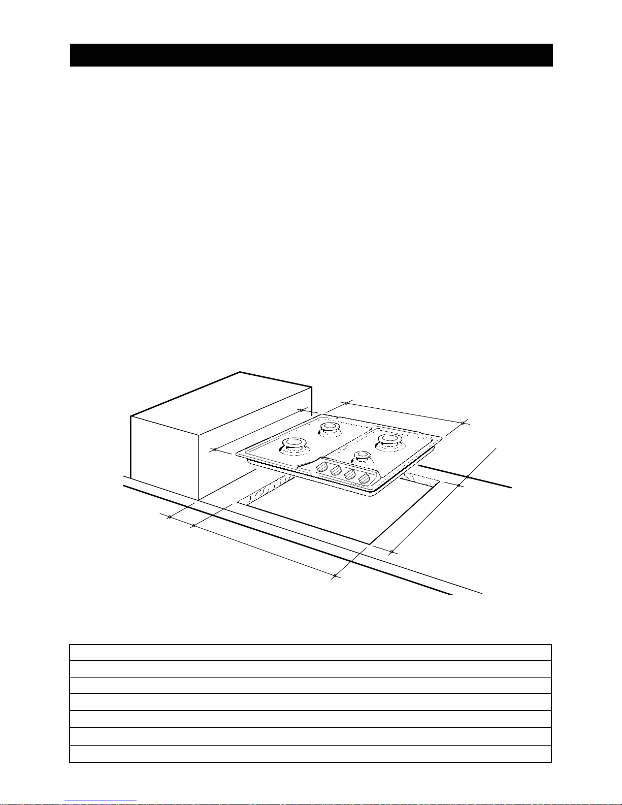
580
550
100
min
500
470
35 min.
Figure 1
DIMENSIONS (Table 2):
(Note: Also refer to Figure 1 side)
General Dimensions
Width 580 mm
Depth 500 mm
Depth Below Mounting Surface 30 mm
Cut-out Dimensions
Width 550 mm
Depth 470 mm
INSTALLATION
CAUTION:
■
This appliance must be installed in accordance with these installation
instructions, local gas fitting regulations, municipal building codes, water
supply regulations, electrical wiring regulations, AS5601 / AG 601 - Gas
Installations and ony other relevant statutory regulations.
■
This appliance shall only be serviced by authorized personnel.
■
This appliance is to be installed only by an authorised person.
■
Incorrect installation, for which the manufacturer accepts no responsibility,
may cause personal injury of damage.
■
Always disconnect the cooker from mains power supply before carrying
out any maintenance operations or repairs.
■
In the room where the cooker is installed, there must be enough air to
allow the gas to burn correctly, according to the current local regulations.
5
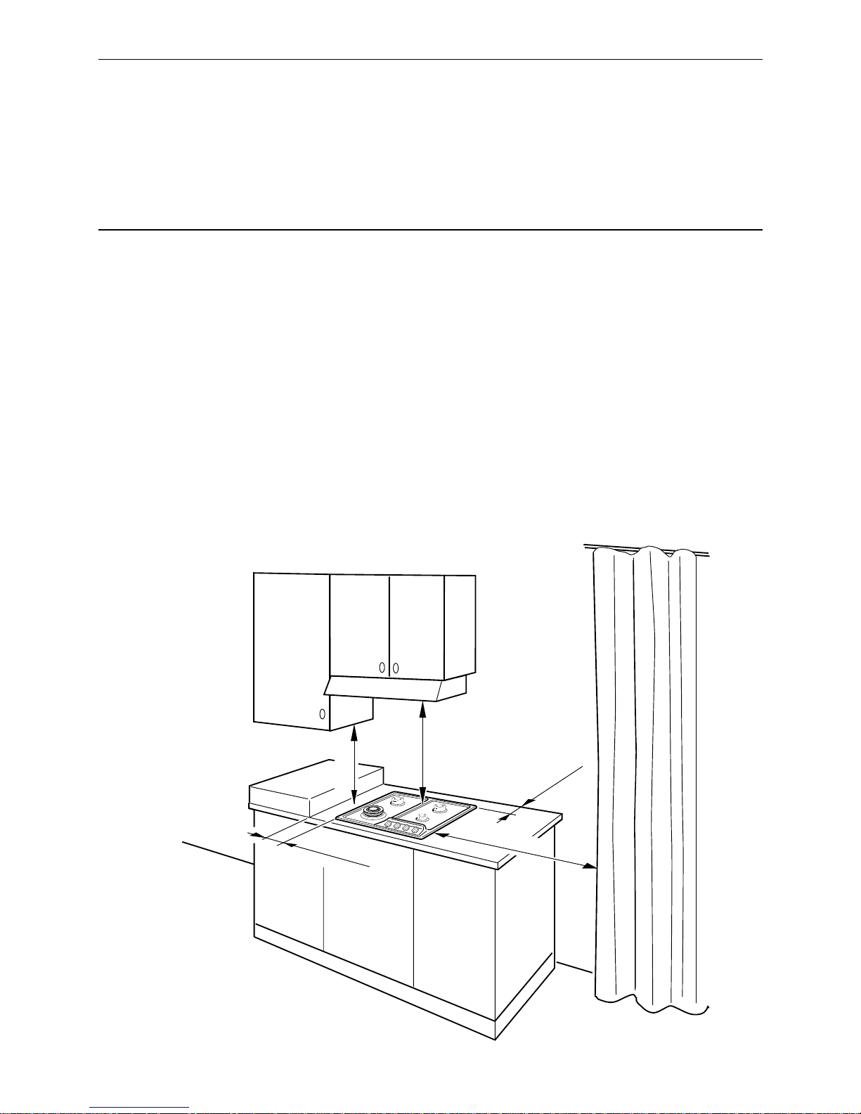
750 mm
35 mm min
100 mm min
500 mm
450 mm
Figure 2
CLEARANCES:
Installation clearances and protection of combustible surfaces shall comply with the
current local regulations e.g. AG 601 (AS 5601) - Gas Installations code.
This cooktop has been designed and constructed in accordance with the following
codes and specifications:
AGA101 (AS 4551) Approval Requirements for Domestic Gas cooking appliances
AS/NZS 3350-1 General Requirements for Domestic electrical appliances
AS/NSZ 3350-2-6 Particular Requirements for Domestic electrical cooking appliances
AS/NSZ 1044 Electromagnetic Compatibility Requirements.
6
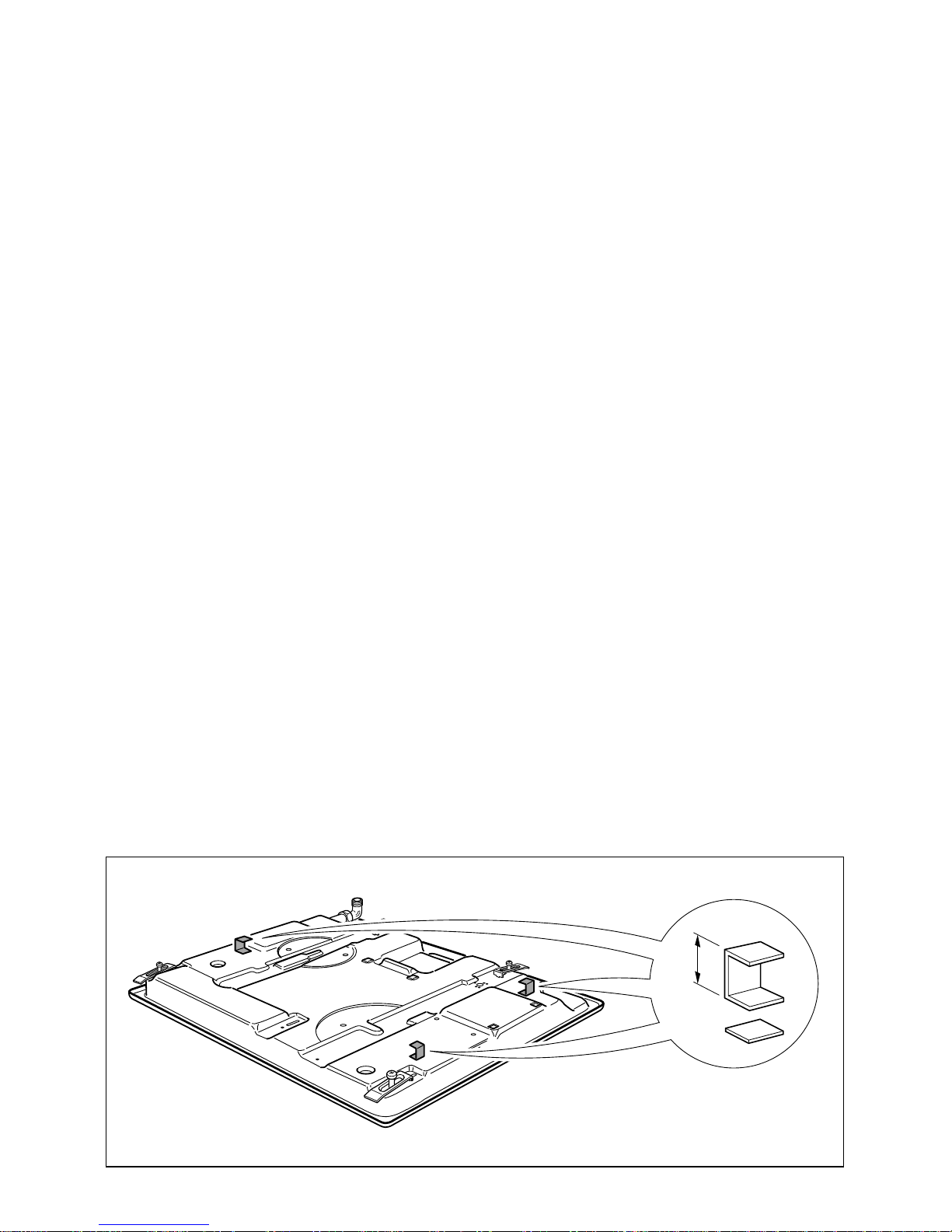
The installation shall comply with the dimensions in Figures 1 and 2, bearing in mind
that:
■ A minimum clearance of 20 mm has to be kept between the bottom of the
cooking hob and the top of an appliance or a shelf. To ensure this clearance
mount the spacers, supplied with the appliance, as shown in the figure below.
■ A partition between the base of the hob and the cupboard below should be
fitted 100 mm below the workbench surface if the cupboard is to be used
for storage.
■ Overhead clearances - In no case shall the clearance between the highest
part of the hob and a range hood be less than 600 mm, or for an overhead
exhaust fan, 750 mm. Any other downward facing combustible surface less
than 600 mm above the highest part of the hob shall be protected for the full
width and depth of the cooking surface area in accordance with local regulations in force. However, in no case shall this clearance to any surface be less
than 450 mm.
■ Side clearances - Where the dimension from the periphery of the nearest
burner to any vertical combustible surface is less than 200 mm, the surface shall
be protected in accordance with with local regulations in force to a height of
not less than 150 mm above the hob for the full dimension (width or depth) of
the cooking surface area.
Where the dimensions from the periphery of the nearest burner to any vertical
combustible surface is less than 200mm, the horizontal surface shall be greater
than 10mm below the surface of the hob, or the horizontal surface requirement above.
■ Protection of combustible surfaces - Local regulations in force specify that
where required protection shall ensure that the surface temperature of the combustible surface does not exceed 65 °C above ambient. The fixing of 5 mm
thick ceramic tiles to the surface or attaching fire resistant material to the surface
and covering with sheet metal with minimum thickness of 0.4mm should be
satisfactory.
Figure 3
20 mm
7
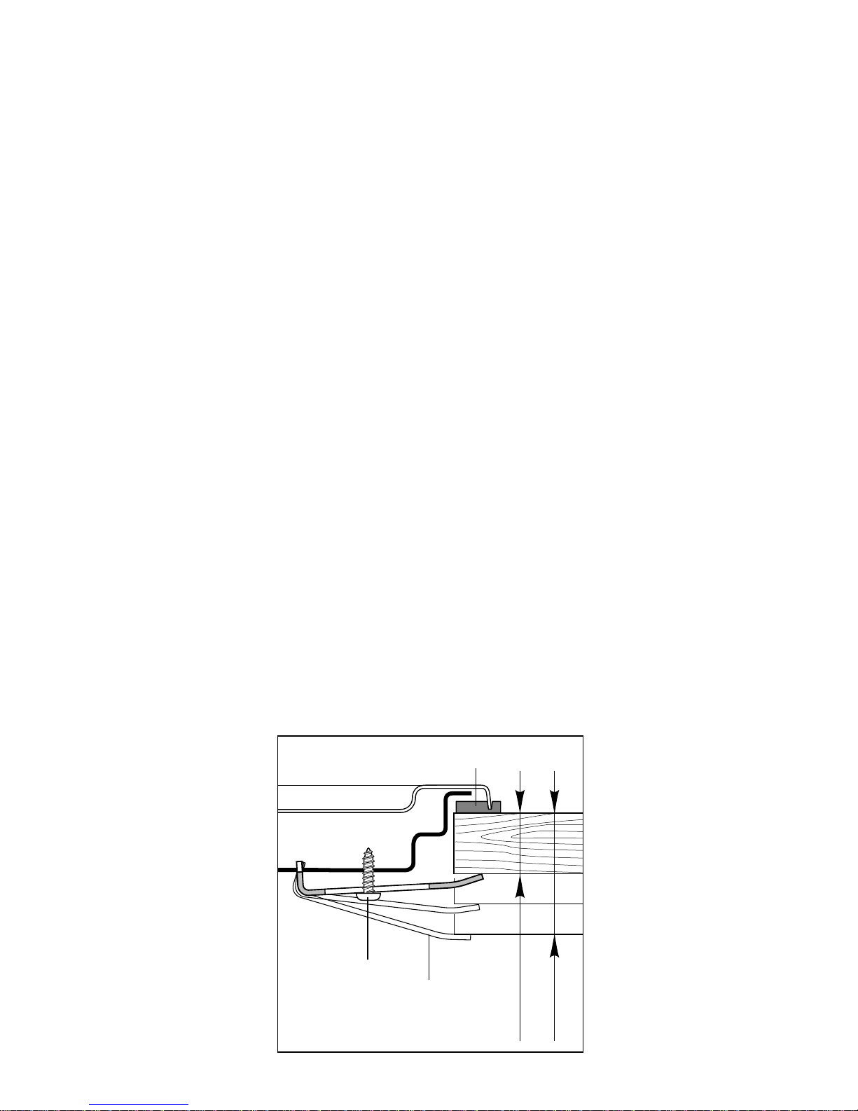
INSTALLATION (Refer to Figure 4):
1. Spread out the gasket “C” over the workbench at the edge of the cut out taking care to overlap the gasket at the corners.
2. Slot in the cooking hob into the cut out of the workbench and locate it correctly.
3. Adjust the clamps “A” and tighten the screws “B” until the hob is firmly secured.
4. Using a sharp tool, trim any excess gasket which protrudes from the edge of
the hob.
Figure 4
20 mm min.
40 mm max.
B
C
A
8
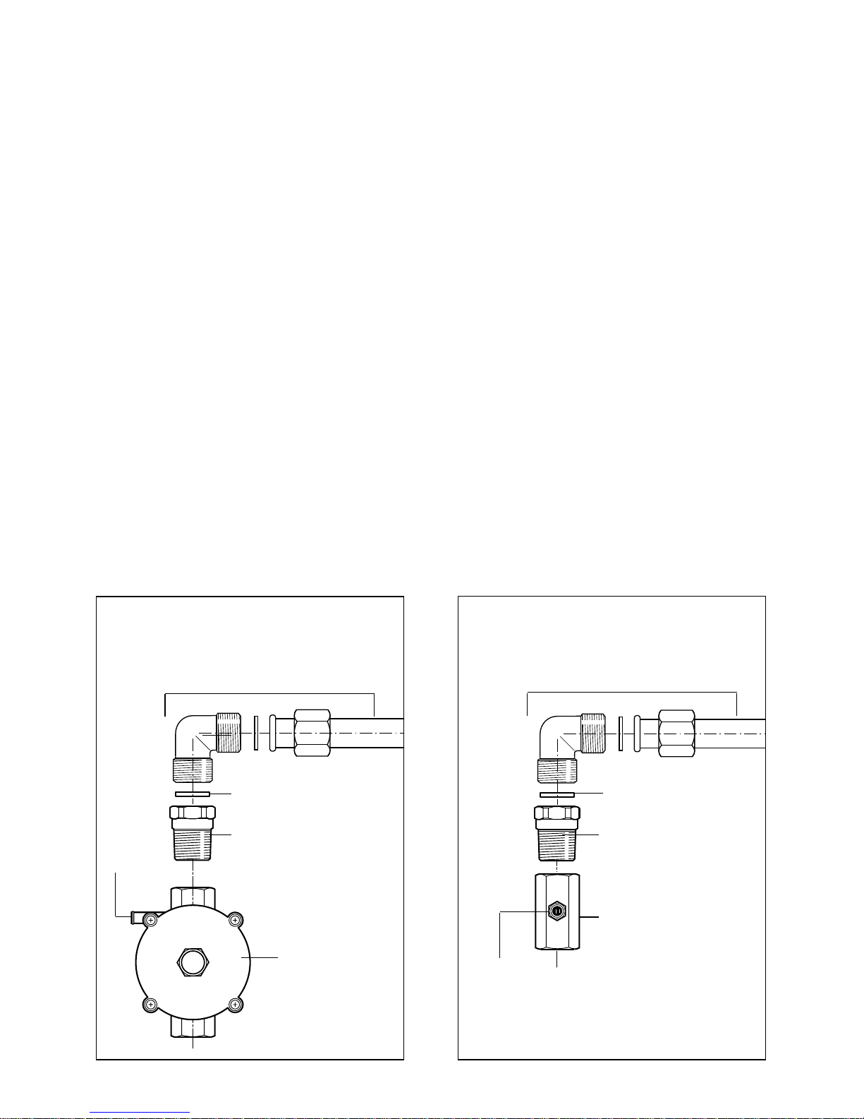
GAS SUPPLY:
■ This appliance is suitable for use with Natural Gas or Propane gas. (Check the “gas
type” sticker attached to the appliance).
■ For Natural Gas the gas supply must be regulated to obtain a pressure of 1 kPa with
the two semi-rapid (SR) burners operating.
■ For Propane gas models connect the gas supply directly to the appliance test point
adaptor (supplied with the conversion kit) and ensure that the supply pressure is regulated to 2.75 kPa.
■ Do NOT force the ”elbow“ rotation prior to loosening nut.
■ Do NOT over tighten the nut at the ”elbow“.
Figure 5b
Figure 5a
Gas connection for
PROPANE GAS
Test point adaptor
Gasket
Brass conical adaptor
(Thread tight: use
suitable seal)
Gas inlet pipe
Test
point
Gas connection for
NATURAL GAS
Gas inlet pipe
Gasket
Brass conical adaptor
(Thread tight: use
suitable seal)
Gas regulator
Test
point
1. After connecting the gas supply, check the piping and connections for leaks using a
soap and water solution. The presence of bubbles indicates a leak, tighten or
replace connections as appropriate.
Warning: Do not use any naked flame to check for leaks.
2. The operation of the appliance MUST be tested before leaving.
3. Adjust the test point pressure or supply pressure to the value which is appropriate
for the gas type.
4. Turn on the appliance gas controls and light each burner. Check for a well defined
blue flame without any yellow tipping. If any abnormality is evident then check that
the burner cap is located properly and the injector nipple is aligned correctly.
 Loading...