

Page 1

Dell Wyse ThinOS Lite Release 2.5
Administrator’s Guide
Page 2

Notes, cautions, and warnings
NOTE: A NOTE indicates important information that helps you make better use of your product.
CAUTION: A CAUTION indicates either potential damage to hardware or loss of data and tells you how to avoid the problem.
WARNING: A WARNING indicates a potential for property damage, personal injury, or death.
© 2017 - 2018 Dell Inc. or its subsidiaries. All rights reserved. Dell, EMC, and other trademarks are trademarks of Dell Inc. or its subsidiaries. Other
trademarks may be trademarks of their respective owners.
2018 - 02
Rev. A01
Page 3

Contents
1 Introduction....................................................................................................................................................6
About this Guide.................................................................................................................................................................6
Technical Support........................................................................................................................................................ 6
What is new in this release................................................................................................................................................6
2 Getting started.............................................................................................................................................. 8
Conguring ThinOS Lite using First Boot Wizard.......................................................................................................... 8
Connecting to a remote server.......................................................................................................................................15
Connecting a remote server manually......................................................................................................................15
Using your desktop...........................................................................................................................................................15
Conguring zero client settings and connection settings............................................................................................16
Connecting to a printer....................................................................................................................................................16
Connecting to a monitor..................................................................................................................................................16
Locking the zero client.....................................................................................................................................................16
Signing o and shutting down........................................................................................................................................ 16
Additional getting started details.................................................................................................................................... 17
Zero desktop features................................................................................................................................................ 17
Login dialog box features...........................................................................................................................................19
Using the system setup menu..................................................................................................................................20
Accessing system information..................................................................................................................................20
3 Global connection settings...........................................................................................................................22
4 Conguring the connectivity........................................................................................................................24
Conguring the network settings.................................................................................................................................. 24
Conguring the general settings..............................................................................................................................24
Conguring the DHCP options settings..................................................................................................................26
Conguring the ENET settings.................................................................................................................................27
Conguring the WLAN settings...............................................................................................................................30
Conguring the proxy settings.................................................................................................................................32
Conguring the remote connections.............................................................................................................................34
Conguring the Citrix broker setup......................................................................................................................... 34
Conguring the visual settings.................................................................................................................................35
Conguring the general options...............................................................................................................................36
Conguring the authentication settings..................................................................................................................38
Conguring the central congurations..........................................................................................................................59
Conguring the general central congurations .....................................................................................................60
Conguring the Wyse Device Agent settings......................................................................................................... 61
Conguring the VPN manager.......................................................................................................................................63
5 Conguring the connection broker.............................................................................................................. 66
Conguring Citrix.............................................................................................................................................................66
Conguring the Citrix broker setup.........................................................................................................................66
Contents
3
Page 4

Citrix HDX RealTime Multimedia Engine—RTME................................................................................................. 67
Citrix Icon refresh.......................................................................................................................................................73
Using multiple audio in Citrix session.......................................................................................................................75
Using Citrix NetScaler with CensorNet MFA authentication............................................................................... 75
Conguring ICA connections.................................................................................................................................... 77
ICA Self Service Password Reset—SSPR..............................................................................................................82
QUMU or ICA Multimedia URL Redirection........................................................................................................... 90
HTML5 Video Redirection........................................................................................................................................ 90
ICA SuperCodec........................................................................................................................................................ 90
Anonymous logon.......................................................................................................................................................94
Conguring the Citrix UPD Printer..........................................................................................................................94
Introduction to Flash Redirection.............................................................................................................................95
6 Conguring Zero Client Settings..................................................................................................................111
Local Settings Menu........................................................................................................................................................111
Conguring the System Preferences...................................................................................................................... 111
Conguring the Display Settings.............................................................................................................................114
Conguring the Peripherals Settings......................................................................................................................119
Conguring the Printer Settings.............................................................................................................................128
Reset Features................................................................................................................................................................133
Resetting to Factory Defaults Using G-Key Reset...............................................................................................133
Resetting to Factory Defaults Using Shutdown Reset........................................................................................133
Resetting Display Settings Using V-Key Reset.....................................................................................................133
7 Performing Diagnostics.............................................................................................................................. 134
System Tools................................................................................................................................................................... 134
Simplied Certicate Enrollment Protocol—SCEP..............................................................................................142
About Default Certicates.......................................................................................................................................144
Using the Troubleshooting Options...............................................................................................................................151
8 BIOS Management..................................................................................................................................... 157
CMOS Central Management—Extracting CMOS Settings to the File Server for Distribution........................... 158
CMOS Local Management—Extracting CMOS Settings to a USB Key for Distribution......................................158
Accessing Zero Client BIOS Settings...........................................................................................................................159
9 Security Changes.......................................................................................................................................160
Security Enhancements—Firmware Signature..........................................................................................................163
Transport Layer Security—TLS.................................................................................................................................... 164
Smart cards and smart card readers............................................................................................................................164
A Central Conguration—Automating Updates and Congurations.............................................................. 165
How to Set Up Automatic Updates and Congurations............................................................................................165
Using DHCP Options..................................................................................................................................................... 165
B Creating and Using xen.ini Files..................................................................................................................169
Downloading and Using Sample INI Files.....................................................................................................................169
Rules and Recommendations for Constructing a xen.ini File....................................................................................169
Parameters for a xen.ini File.......................................................................................................................................... 170
TimeZone Parameter—Values..................................................................................................................................... 220
Contents
4
Page 5

TimeZone Parameter—Values................................................................................................................................ 221
C Examples of Common Printing Congurations...........................................................................................226
Local USB for Printing...................................................................................................................................................226
Using the Printer Setup Dialog Box for Local USB Printers............................................................................... 226
Using INI Parameters for Local USB Printers....................................................................................................... 227
Printing to Non-Windows Network Printers—LPD...................................................................................................227
Using the Printer Setup Dialog Box for Non-Windows Network Printers—LPD............................................ 227
Using INI Parameters for Non-Windows Network Printers—LPD....................................................................228
Windows Network Printers for Printing—SMB.........................................................................................................228
Using the Printer Setup Dialog Box for Windows Network Printers—SMB....................................................228
Using INI Parameters for Windows Network Printers—SMB........................................................................... 229
Using Your Zero Client as a Print Server—LPD.........................................................................................................230
Using the Printer Setup Dialog Box for Conguring LPD Services................................................................... 230
Setting Up Windows 2003 or 2008 Servers........................................................................................................ 230
Using INI Parameters for Conguring LPD Services...........................................................................................230
Conguring ThinPrint.....................................................................................................................................................231
D Important Notes........................................................................................................................................232
E Troubleshooting......................................................................................................................................... 233
F Firmware upgrade...................................................................................................................................... 234
Firmware upgrade using FTP server........................................................................................................................... 234
Firmware upgrade using HTTP or HTTPS..................................................................................................................235
Firmware upgrade using Wyse Management Suite version 1.1................................................................................. 236
Contents
5
Page 6

1
Introduction
The Dell Wyse ThinOS Lite family of products are zero clients built for Citrix XenApp and XenDesktop environments. These products
represent an entirely new approach in delivering virtual desktops. ThinOS Lite zero clients deliver a Citrix HDX experience with zero delays,
zero management, zero security risks, and almost zero energy use. Users will benet from an instant-on, plug-n-play, high performance
zero client while administrators can have following privileges such as virus resistant, hands-o, self-updating zero client deployed.
About this Guide
This guide is intended for administrators of thin clients running ThinOS Lite. It provides information and detailed system congurations to
help you design and manage a ThinOS Lite environment.
Supported Products
This guide is intended for the following Dell Wyse ThinOS Lite products:
• Wyse 5010 zero client for Citrix (D00DX) (ThinOS Lite Pro 2)
• Wyse 3010 zero client for Citrix (T00X) (ThinOS Lite 2)
• Wyse 3020 zero client for Citrix (T00DX) (ThinOS Lite 3)
• R00LX (ThinOS Lite Pro)
• C00X (ThinOS Lite)
Finding the Information You Need in this Guide
You can use either the Search window or Find toolbar to locate a word, series of words, or partial word in an active PDF document. For
detailed information on using these features, refer to the Help in your PDF reader.
Technical Support
To access technical resources self-service portal, knowledge base, software downloads, registration, warranty extensions/ RMAs, reference
manuals, and so on, visit www.dell.com/wyse/support . For Customer Support, visit www.dell.com/support/contents/us/en/19/article/
Contact-Information/International-Support-Services/international-contact-center?ref=contactus , and phone numbers for Basic and Pro
Support are available at www.dell.com/supportcontacts.
: Before proceeding, verify if your product has a Dell service tag. For Dell service tagged products, go to www.dell.com/
NOTE
support/contents/us/en/19/article/Product-Support/Dell-Subsidiaries/wyse.
What is new in this release
The following are the updates or new features in this release:
• ThinOS Lite package updates—Updated ThinOS Lite packages to a newer version. See, Dell Wyse ThinOS v2.5 Release Notes
BIOS updates—Added new parameters for BIOS management. See, Creating and Using xen.ini Files
ThinOS UI-based updates:
Added a rst boot wizard (Out-of-Box-Experience—OOBE) for a new or factory reset thin client. See, First Boot Wizard.
6 Introduction
Page 7

Added a desktop wallpaper. Dell Wyse ThinOS v8.5 Release Notes.
Added the About tab in System Information. See, Accessing system information.
Added option to capture, and export screenshots. See, Using the troubleshooting options.
Added option to export the INI le. See, Using the troubleshooting options.
Citrix-based updates:
Added support for multiple audio in a Citrix session. See, Using multiple audio in Citrix session.
Added support for SMS PASSCODE authentication on a Citrix NetScaler Gateway. See, Using Citrix NetScaler with CensorNet MFA
authentication.
Added support for Wyse Management Suite version 1.1. See, Conguring the WDA settings.
Introduction 7
Page 8

Getting started
Use the following information to quickly learn the basics and get started using your zero client:
• Connecting to a Remote Server
• Using Your Desktop
• Conguring Zero Client Settings and Connection Settings
• Connecting to a Monitor
• Connecting to a Printer
• Locking the Zero Client
• Signing O and Shutting Down
• Additional Getting Started Details
NOTE: ThinOS Lite is centrally managed and congured using INI les to automatically push updates and any desired default
conguration to all supported zero clients in your environment. For more information, see Central Conguration: Automating
Updates and Congurations.
If no INI les are detected, you can use local dialog boxes on each zero client to make available congurations. ThinOS Lite will save
many of these locally congured settings such as resolution, mouse, and keyboard to persist after reboot. However, once INI les are
detected, rebooting causes ThinOS Lite to become stateless while ignoring locally congured settings after a reboot and then the
settings contained in the INI le will be used.
2
Conguring ThinOS Lite using First Boot Wizard
First Boot Wizard, also called First Boot Wizard, runs the rst time you start a new thin client that runs on ThinOS Lite v2.5. The thin client
launches the out-of-box experience application before you enter the ThinOS Lite desktop, and allows you to perform a set of tasks, such
as, conguring system preferences, setting up the internet connectivity, loading USB congurations, conguring management software,
and conguring broker connections. The thin client congures settings that are applied during the rst-boot experience, and processes
before your log into ThinOS Lite.If you are an existing thin client user, and you have upgraded to ThinOS Lite v2.5, then you can reset your
thin client to factory default settings to enter First Boot Wizard.
The following owcharts represent the First Boot Wizard workow:
8 Getting started
Page 9
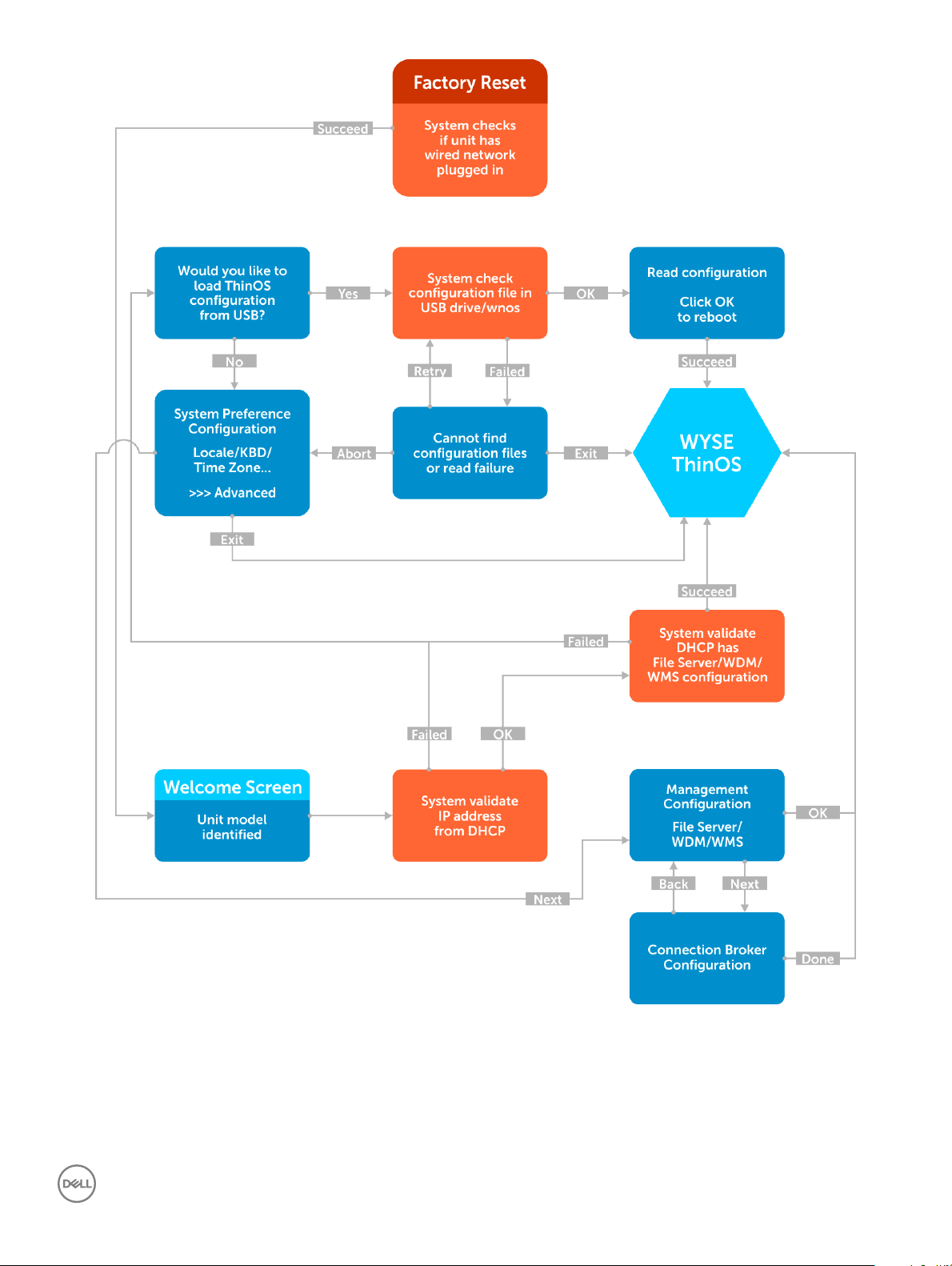
Figure 1. First Boot Wizard_Success
Getting started
9
Page 10
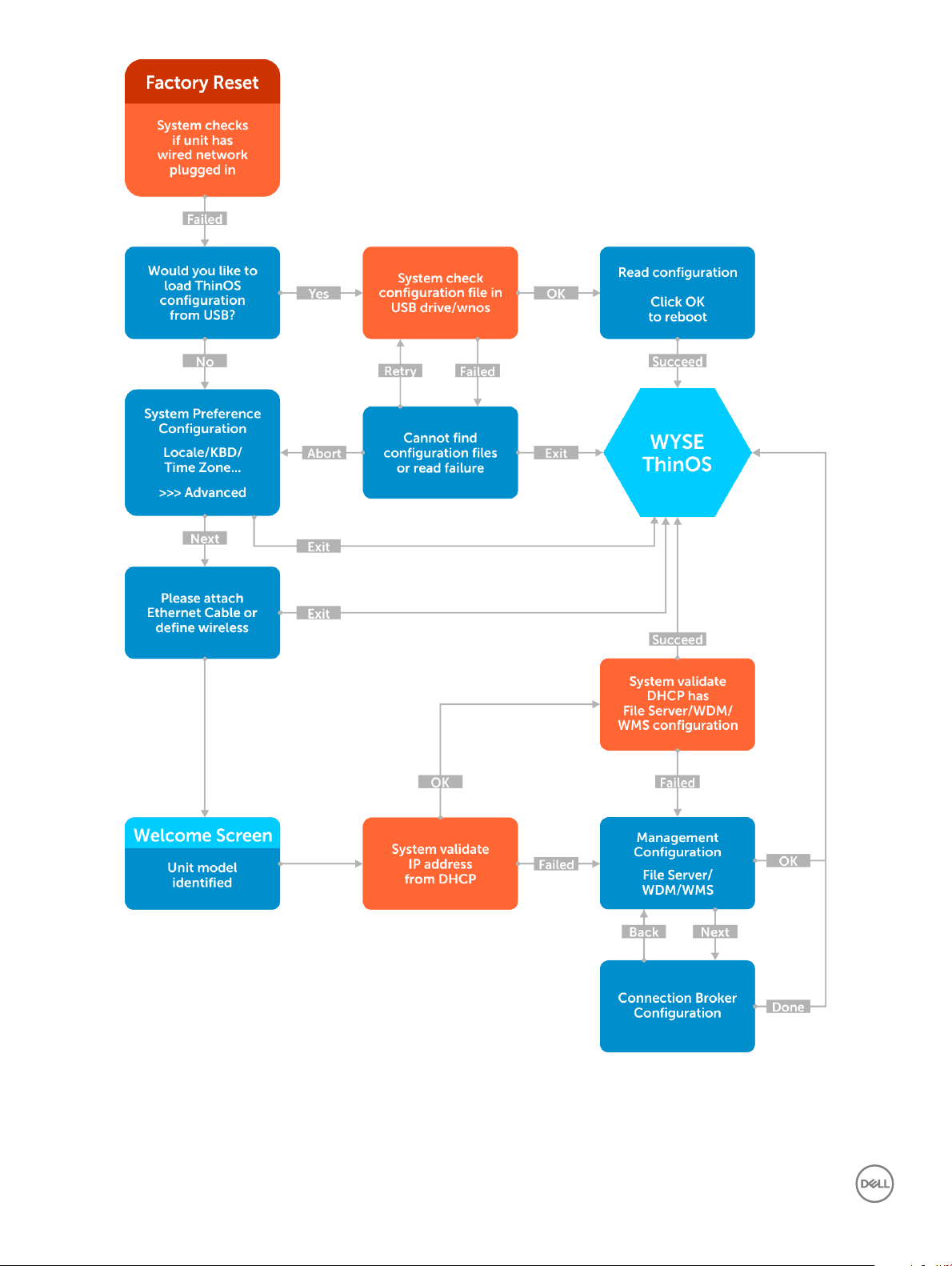
Figure 2. First Boot Wizard _Failure
Getting started
10
Page 11
1 Connect a new zero client or existing zero client to the Ethernet using a wired connection. The existing zero client must be reset to
factory default settings to enter First Boot Wizard.
2 Turn on your zero client.
The zero client checks for a wired network connection. If the network connection is successful, a welcome screen with the model
name of your zero client is displayed.
The zero client validates the IP address from DHCP. If the DHCP contains the le server or Wyse Device Manager or Wyse
Management Suite congurations, then the ThinOS Lite system desktop is loaded without entering First Boot Wizard. If the DHCP
validation fails or if you have not connected to Ethernet, then follow the next step.
NOTE: To exit First Boot Wizard during the network connection status check on the welcome screen, press the Ctrl + Esc
key.
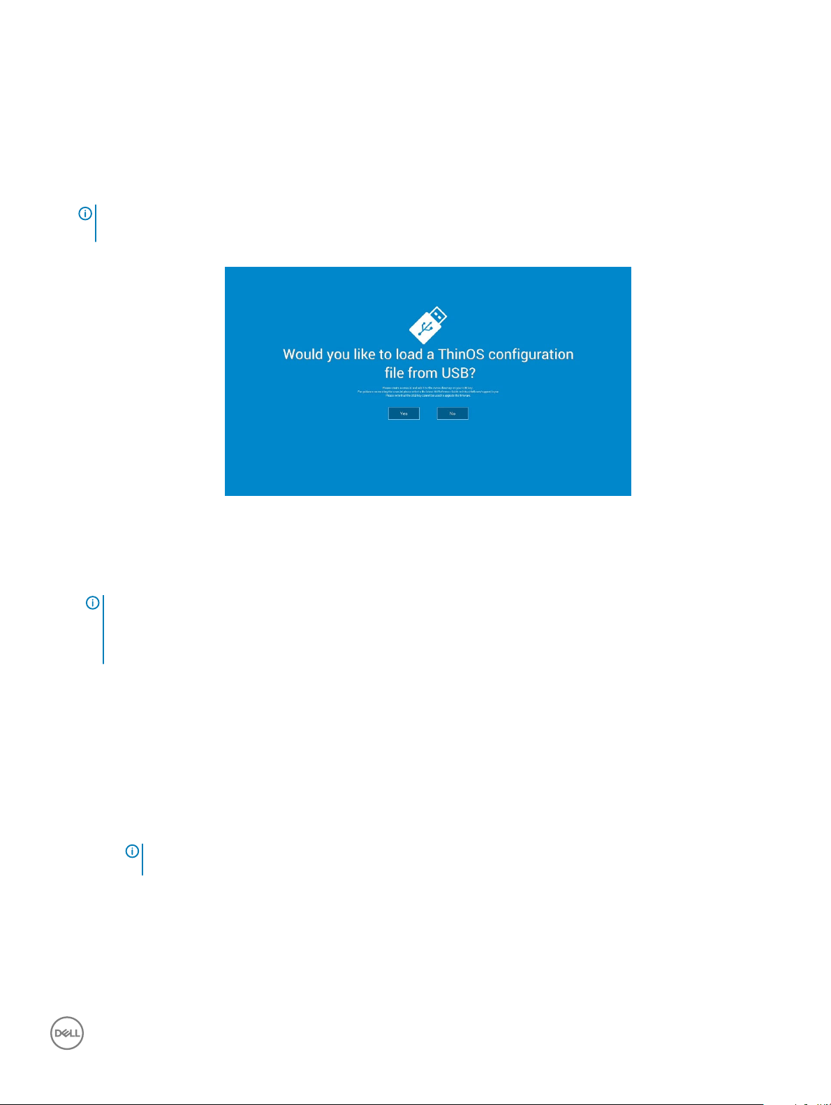
3 On the Would you like to load a ThinOS Lite conguration le from USB? screen, do either of the following:
Figure 3. USB conguration
• To load a ThinOS Lite conguration le from the USB drive, ensure that you create a xen.ini le and add the le to the /xen
directory on the USB drive. Plug the USB drive to zero client, and click Yes.
NOTE
:
Only FAT, FAT32, and ExFAT le systems on the USB disk are supported. NTFS le system is not
supported.
The zero client validates the conguration le in the USB drive.
– If the ThinOS Lite conguration le in the USB drive is correct, the Read conguration success message is displayed. Click
OK to exit First Boot Wizard, and log in to ThinOS Lite system desktop.
– If the ThinOS Lite conguration le in the USB drive is corrupted or the required le is not available, then the Can not nd
conguration les, or read conguration failure message is displayed. Upload the correct le on the USB drive, plug the USB
drive again, and then click Retry. If the le is correct, the Read conguration success message is displayed. Click OK to exit
First Boot Wizard, and log in to ThinOS Lite system desktop.
If you do not want to use the Retry option to load the ThinOS Lite conguration le, then click Abort to enter the System
Preferences conguration setup.
: To exit the Can not nd conguration les, or read conguration failure message screen, and load the
NOTE
ThinOS Lite system desktop, click Exit.
• To enter the System Preferences conguration setup, click No.
4 On the System Preferences Conguration screen, congure the following options:
Getting started
11
Page 12
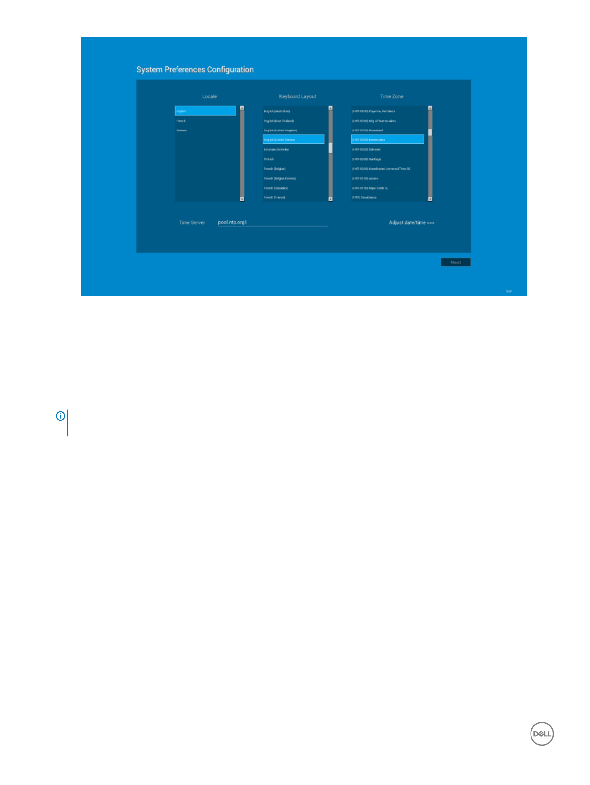
Figure 4. System preferences conguration
• Locale—Select a language to start ThinOS Lite in the regional specic language.
• Keyboard Layout—Select a keyboard layout to set the keyboard layout in the regional specic language.
Time Zone—Select a time zone to set the time zone for your zero client.
• Time Server—Displays the IP addresses or host names with optional port number of time servers.
• Advanced—Click Advanced to congure settings, such as daylight saving, time format, date format, and time servers.
NOTE
: To exit the System Preferences Conguration screen, and load the ThinOS Lite system desktop, click
Exit.
If you are not connected to Ethernet, you cannot continue with the setup, and the Attach the Ethernet cable screen is displayed. Do
either of the following:
• Connect the Ethernet cable to the zero client.
• Click Dene a wireless connection. From the list, select a wireless network, and click Connect.
12
Getting started
Page 13
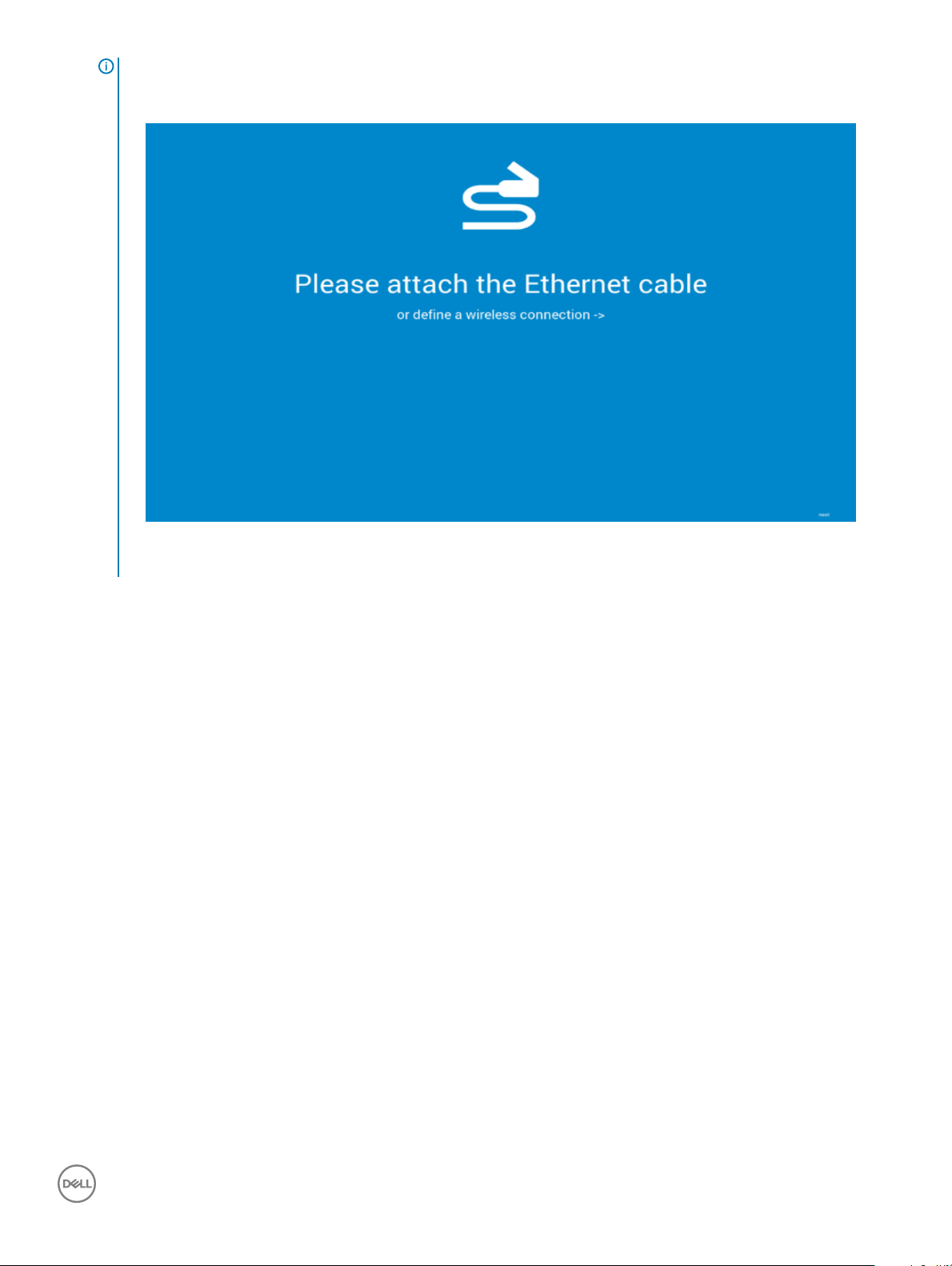
NOTE:
– The option to dene a wireless connection is not available on zero clients without a WLAN module.
– To exit the Attach the Ethernet cable screen, and load the ThinOS Lite system desktop, click Exit.
Figure 5. Ethernet cable
After the connection is established, the zero client validates the IP address from DHCP. If the DHCP contains the le server or Wyse
Device Manager or Wyse Management Suite congurations, then the ThinOS Lite system desktop is loaded. If the DHCP validation
fails, or the network connection fails, then the Management Conguration screen is displayed. Follow the steps 6-9.
5 Click Next to enter the Management Conguration setup.
6 On the Management Conguration screen, congure the following:
Getting started
13
Page 14
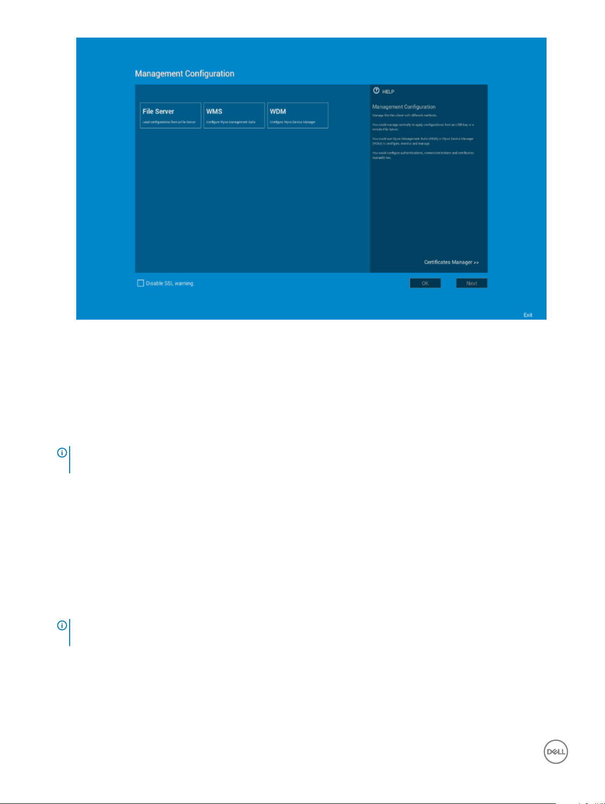
Figure 6. Management conguration
• File Server—Enter the le server details to apply congurations including INI les from a le server.
• WMS—Enter the group registration key and the Wyse Management Suite server URL to register the zero client to the Wyse
Management Suite.
• WDM—Enter the IP addresses or host names.
• Disable SSL warning—Select this check box to disable the SSL (Secure Sockets Layer) connection warnings.
• Certicates Manager—Click Certicates Manager to import or request a certicate.
NOTE
: To exit the Management Conguration screen, and load the ThinOS Lite system desktop, click
Exit.
7 Click Done to exit First Boot Wizard or click Next to enter the Connection Broker Conguration setup.
8 On the Connection Broker Conguration screen, congure the Citrix broker connection. The broker allows you to connect to full
desktops using XenDesktop or individual applications using XenApp from a centralized host through Citrix Receiver Client.
• Server Address—Enter the host name or IP address of the broker connection.
• Enable theme: ThinOS Lite—Select this check box to boot the zero client in ThinOS Lite mode.
• StoreFront style—Select this check box to enable the Citrix StoreFront based layout of published applications and desktops on
the zero client.
• Certicates Manager—Click Certicates Manager to import or request a certicate.
• Disable SSL warning—Select this check box to disable the warnings for your SSL (Secure Sockets Layer) connection.
9 Click Done.
: To congure the Management Conguration setup again, click Back, and follow the steps 6 and
NOTE
7.
The device exists from First Boot Wizard mode, and the ThinOS Lite desktop is displayed.
Getting started
14
Page 15

Connecting to a remote server
On your initial connection to central conguration, we recommended that you connect using a wired connection plug in the network-
connected Ethernet cable to your zero client before starting the zero client to obtain the congurations desired by the administrator. This
wired connection will also provide any wireless congurations provided by the administrator through INI les.
If you must initially connect to central conguration through wireless, use the Wireless tab in the Network Setup dialog box to enter the
SSID and encryption congurations required or set up by the network administrator.
Central Conguration — If you are congured for automatic detection using INI les — see the Parameters for a xen.ini File in this guide,
your zero client will automatically detect and connect to the congured remote services during the boot-up process. Press the power
button to turn on your zero client to see the Login dialog box. Enter your User name, Password, and Domain, and then click Login. After
authentication is successful, your available connections are presented.
Manual Connection — If you are not yet set up for central conguration, you will see the Zero Toolbar, where you can congure the initial
server connection you want using the Remote Connections dialog box before you can log in. For more information, see Connecting to a
Remote Server manually.
You only need to complete this manual conguration once or after reboot to factory defaults. After the zero client knows the location of
your server, it automatically connects to the server for login when you start the zero client in the future. After you conrm that your
environment is ready for deployment, you can create INI les for central conguration.
Connecting a remote server manually
To connect a Remote Server manually, complete the following tasks:
1 From the oating bar menu, click the System Setup , and then click Remote Connections. The Remote Connections dialog box is
displayed.
2 Click the Broker Setup tab of the Remote Connections dialog box to congure one of the following connections:
• A specic Citrix broker server connection — Enter the IP Address of the server in the Broker Server box.
NOTE
: For more details, see Conguring the Remote
Connections.
3 Click OK, and then restart the zero client.
Click the Shutdown icon on the Zero Toolbar to open, and use the Shutdown dialog box to restart the zero client.
NOTE
:
If a Specic Broker Server Connection is congured— After zero client restart, the Login dialog box appears for your server.
Enter the User name, Password, and Domain and click Login. After authentication is successful, your Zero Toolbar is presented
with your assigned connections dened by the broker server.
Using your desktop
What you view after logging on to the server depends on the administrator congurations.
• Users with a zero desktop - will see the zero desktop with the zero toolbar showing the assigned list of connections from which to
select. This option is recommended for VDI and any full-screen only connections. For more information on using the zero desktop, see
Zero Desktop Features.
Getting started
15
Page 16

Conguring zero client settings and connection
settings
While the use of INI les is recommended to congure zero client settings and connection settings available to users . For more information,
refer How to Set Up Automatic Updates and Congurations. You can use the dialog box on a zero client to:
• Set up your zero client hardware, look and feel, and system settings, see Conguring Zero Client Settings Locally.
• Congure connection settings, see Conguring Zero Client Settings Locally.
Connecting to a printer
To connect a local printer to your zero client, be sure you obtain and use the correct adapter cables which are not included. Before use, you
may need to install the driver for the printer by following the printer driver installation instructions.
Connecting to a monitor
Depending on your zero client model, connections to monitors can be made using either a VGA (analog) monitor port, a DVI (digital)
monitor port, or a DisplayPort (digital) and the proper Dell monitor cables/splitters/adapters.
NOTE:
For dual-monitor supported zero clients— when using a DVI to DVI/VGA splitter, ensure that the DVI monitor will be the primary
monitor; when using a DisplayPort, ensure that the DisplayPort monitor will be the primary monitor.
Locking the zero client
To help ensure that no one else can access your private information without permission, ThinOS Lite allows you to lock your zero client so
that credentials are required to unlock and use the zero client after you do one of the following:
• Unplug a signed-on smart card — If an administrator has set SCRemovalBehavior=1 for the Signing parameter in the INI les and you
unplug the smart card that you used to sign on to the zero client, then the zero client will lock. To unlock the zero client for use, you
must use the same smart card and your correct PIN. Note that removing a signed-on smart card can also cause the zero client to log-
o, if an administrator has set the INI les to do so in this case you must sign-on as usual to use the zero client.
• Use LockTerminal from the Shortcut Menu and Shutdown dialog box — On the Zero Desktop, use the Shutdown dialog box, for
more information, see Signing O and Shutting Down. To open the zero client for use, you must use your correct credentials.
• Use the screen saver — If an administrator has set LockTerminal=2 for the ScreenSaver parameter, and when the screen saver is
activated, then the thin client is locked. To unlock the thin client, enter the login password in the unlock dialog box. However, you
cannot see the wallpaper while using the unlock dialog box.
Signing o and shutting down
Use the Shutdown dialog box to select the available option you want:
• Zero Desktop — Click the Shutdown icon on the Zero Toolbar.
NOTE
: You can also congure automatic behavior after all desktop sessions are closed by using the Remote Connections dialog
box, see Central Conguration: Automating Updates and Congurations.
16 Getting started
Page 17

Additional getting started details
This section includes additional details, such as Zero desktop features, Login dialog box features, System setting menu, and System
information.
Zero desktop features
This section includes information on:
• Zero Interactive Desktop Guidelines
• Zero Toolbar
• List of Connections
Zero interactive desktop guidelines
The Zero Desktop has a default background with the Zero Toolbar at the left of the screen.
The following table lists the available Zero Desktop shortcuts:
Table 1. Zero Desktop shortcuts
Action Press
Display the Zero Toolbar Ctrl+Alt+UpArrow
Open a selection box for toggling between the desktop and currentlyactive connections
Lock the zero client Ctrl+Alt+LeftArrow
Keyboard shortcuts to menu commands Left-Alt+UnderlinedLetter
Capture the full desktop to the clipboard Print Screen
Capture the active window to the clipboard Alt+PrintScreen
NOTE:
• You can copy and paste between application sessions and between sessions and the desktop, however, this function depends on
session server congurations.
• In addition to the standard two-button mouse, the zero client supports a Microsoft Wheel Mouse used for scrolling. Other similar
types of a wheel mouse may or may not work.
Ctrl+Alt+DownArrow
or
Ctrl+Alt+RightArrow
or
Right-Alt+UnderlinedLetter
To switch the left and right buttons, use the Peripherals dialog box, see Conguring the Peripherals Settings.
Getting started
17
Page 18
Zero toolbar
The Zero Toolbar usually appears at the left corner of the Zero Desktop. However, depending on administrator congurations, the toolbar
can be removed or hidden. It is shown only when a user moves the mouse pointer over the left edge of the desktop screen.
Table 2. Toolbar icons
Icon What It Does
Home Opens the list of available connections, see List of Connections.
System Information Displays zero client system information, see Accessing System
Information.
System Settings Opens the System Settings menu to congure zero client system
settings and perform diagnostics, see Conguring Zero Client
Settings.
Shutdown Terminal Click the Shutdown Terminal icon to use the Shutdown options
available on the zero client, see Signing O and Shutting Down.
Note that the Shutdown Terminal icon does not display on the
toolbar when using the Admin Mode button to congure system
settings.
NOTE:
If congured to display by an administrator, the current date and time are shown on the Zero Toolbar. The zero client is capable of
synchronizing its clock to time provided by a Simple Network Time Protocol (SNTP) server.
List of connections
On the Zero Toolbar, you can click the Home icon to open your list of assigned connections. In some cases, the list may contain only default
connections.
Use the following guidelines depending on user privilege level, some options may not be available for use:
Table 3. Connection Options
Option What It Does
Name of the connection Opens the connection you want
to use.
NOTE: All open
connections display a
blue icon to the left of
the connection name in
the list.
Reset icon Resets the connection.
18 Getting started
Page 19

NOTE: It is useful when
a connection is not
functioning properly or
you need to reboot the
connection.
Close icon Closes the connection.
NOTE: The Close icon is
grayed out for
connections that are not
open.
Edit icon Opens the Connection Settings
dialog box, see Advanced Details
on Conguring ICA Connections
to change the connection
options.
NOTE: Depending on
user privilege level,
editing options may not
be available for use.
Conguring Global Connection
Settings
If you do not use INI les to
provide global connection
settings, you can click Global
Connection Settings to open
and use the Global Connection
Settings dialog box to congure
settings that aect all of the
connection in the list.
Login dialog box features
While the Login dialog box allows you to log on to the server, it also allows you to:
• Obtain system information.
• Access Admin Mode to congure zero client settings.
• Change or reset your own password and unlock your account.
• Open the Shutdown dialog box by using CTRL+ALT+DELETE.
In the Login dialog Box, use the following guidelines:
• System Information — Click the Sys Info button to open the System Information dialog box. You can view the zero client system
information such as System Version, IP Address, information on devices connected to your zero client, event logs and so on.
• Admin Mode — Click the Admin Mode button to congure various settings locally on the zero client other than broker desktop
congurations. For example, you can choose to manually congure the Citrix Xen Broker Server URL or override the URL that is
centrally dened by le servers by using the Remote Connections dialog box as described in Remote Connections
– Zero Desktop — Use the Leave Administrator Mode option in the Shutdown dialog box, or use the Leave Administrator Mode icon
(X) in the upper-right pane of the System Settings menu.
:
NOTE
– By default the Admin Mode button is not displayed on the log on dialog box. You can display it by selecting the Show local
admin button check box in the Shutdown dialog box, see Signing O and Shutting Down.
– By default there is no password needed for Admin Mode button use. You can password protect the Admin Mode button (to
require login credentials) by using the AdminMode parameter in a wnos.ini le, see the INI section in this Guide.
Getting started 19
Page 20

• Shutdown — Press CTRL+ALT+DELETE to open and use the Shutdown dialog box to sign o, shut down, restart, reset the system
setting to factory defaults, and so on. For information, see Signing O and Shutting Down.
• Account Self-Service — Click the Account Self-Service icon shown when congured using the AccountSelfService option of the
PasswordServer INI parameter to open and use the Account Self-Service dialog box to change or reset your own password and unlock
your account. For information on INI parameter, see the INI section in this Guide.
This process assumes that the security questions and answers have been pre-registered by the user inside of their Windows environment.
Users must use HTTPS (not HTTP) for an account self-service server address such as https://IPAddress, in the Broker Setup tab.After
answering the security questions, your new password will be set or your account will be unlocked.
Using the system setup menu
To access the system setup menu:
1 Click System Setup from Zero Toolbar.
The System Setup Menu is displayed.
2 On the system setup menu, you are able to view and use the following options:
a Network Setup — Allows selection of DHCP or manual entry of network settings, as well as entry of locations of servers
essential to zero client operation. This menu selection is disabled for Low-privileged users. See
Settings
b Remote Connections — Allows you to congure zero client network connections for Citrix Xen. For more information, see
Conguring the Remote Connections.
c Central Conguration — Allows you to congure zero client central connection settings such as le server and optional WDM
server settings. For more information, see Conguring the Central Congurations.
d VPN Manager — Allows you to congure zero client VPN manager. For more information, see Conguring the VPN Manager.
e System Preference — Allows user selection of zero client parameters that are matter of personal preference. For more
information, see Conguring the System Preferences.
f Display — Allows you to congure the monitor resolution and refresh rate. For more information, see Conguring the Display
Settings.
g Peripherals — Allows you to select the peripherals settings such as keyboard, mouse, volume and touch screen settings. For
more information, see Conguring the Peripherals Settings.
h Printer — Allows conguration of network printers and local printers that are connected to the zero client. For more
information, see Conguring the Printer Settings.
i System Tools — Opens a submenu from which the xen.ini and user.ini windows can be opened to view the contents of the les.
See System Tools.
j Trouble shooting Options — Displays Performance Monitor graphs that display client CPU, Memory and Networking
information and trace route response messages. For more information, see
Tools.
.
Using the Trouble Shooting Options and System
Conguring the Network
Accessing system information
Use the System Information dialog box to view system information:
• Zero Desktop — Click the System Information icon on the Zero toolbar.
The System Information dialog box includes:
• General tab — Displays general information such as System Version, Serial Number, Memory Size (Total and Free), CPU Speed, ROM
Size, Monitor, Parallel ports, Terminal Name, Boot from, Memory speed, SSD size, Resolution and Serial ports.
• Copyright/Patents tab — Displays the software copyright and patent notices.
• Acknowledgements button is added under Copyrights tab in System Information. This button is related to third party software and is
available only in following clients:
– Wyse 5010 Zero Client for Citrix — D00DX (ThinOS Lite Pro 2)
Getting started
20
Page 21

• Event Log tab — Displays the zero client start-up steps normally beginning from System Version to Checking Firmware or error
Messages that are helpful for debugging problems. The details about the monitors connected to the zero client are also displayed.
• Status tab — Displays status information about TCP performance related parameters, UDP performance related parameters, CPU
Busy, System Up Time, CCM status, Free Memory, Active sessions, and WDM status.
• IPv6 tab — Displays IPv6 information such as Link-local Address, IPv6 Address and IPv6 Default Gateway.
• ENET tab — Displays information about wired network information.
• WLAN tab — Displays information about wireless network information.
• About tab—Displays information about ThinOS Lite operating system. The following attributes are listed:
– Platform name
– Operating system type
– Build name
– Build version
– BIOS name
– BIOS version
– Citrix Broker or Receiver version—This represents ICA revisions between the ThinOS Lite versions.
– Dell vWorkspace version
– Imprivata version
– Caradigm version
– SECUREMATRIX version
– HealthCast version
: This tab is displayed when IPv6 is enabled in the General tab of the Network Setup dialog box, see Conguring the
NOTE
Network Settings.
• Kernel mode—The components are implemented in Kernel according to the specication. The version is displayed as [max].[min],
which is the base version of protocol or server or client of the component. For example, the Imprivata version is 5.2, and so on.
• User mode—The components are from the source, or binaries from third party that are compiled or integrated into ThinOS Lite.
The version is displayed as [max].[min].[svn_revision]. The [max] and [min] is the base version of the third component, and the
[svn_revision] is the source control revision of ThinOS Lite. Using the ThinOS Lite specied version, you can identify the changes
between dierent revisions. For example, the Citrix Receiver version is 14.0.44705. The components are matched to the installed
packages. If the packages are removed, the eld remains empty in the About tab.
Getting started 21
Page 22

3
Global connection settings
If you do not use INI les to provide central conguration (global connection settings) to users, you can use the Global Connection Settings
dialog box to congure settings that aect all of the connections in your list of connections:
To Congure the Global Connection Settings:
1 From the oating bar menu, click the Home icon, and then click Global Connection Settings.
The Global Connection Settings dialog box is displayed.
2 Click the Session tab to select the check boxes you want for the options that are available to all sessions.
• The Smart Card check box species the default setting for connecting to a smart card reader at startup.
• When using the Disks check box for automatic connection to connected USB sticks, use the following guidelines:
– More than one disk can be used at the same time, however, the maximum number of USB sticks including dierent subareas is
12.
– Be sure to save all data and sign o from the session mapping the USB stick before removing the USB stick.
IMPORTANT
22 Global connection settings
: The gure shown is an example for Zero Desktop.
Page 23

NOTE:
ICA sessions always have automatic connection to attached smart card readers.
NOTE: USB devices redirection— By default, audio, video and printer devices will not use HDX USB for redirection. You can
make selections for USB device redirection on the Session tab of the Global Connection Settings dialog box.
Click ICA tab to select the check boxes you want for the options that are available to all ICA sessions. Select the audio quality
3
optimized for your connection.
NOTE:
• Map to — When a drive is entered, maps a disk under the drive.
Global connection settings 23
Page 24

Conguring the connectivity
This chapter helps you to understand various conguration settings for a secure connection. Connectivity menu includes:
• Conguring the Network Settings.
• Conguring the Remote Connections.
• Conguring the Central Congurations.
• Conguring the Caradigm Vault Server.
• Conguring objects on Imprivata Server.
• Conguring the VPN Manager.
Conguring the network settings
To congure the network settings use the following options:
• Conguring the General Settings
• Conguring the DHCP Options Settings
• Conguring the ENET Settings
• Conguring the WLAN Settings
4
Conguring the general settings
To congure the general network settings:
1 From the oating bar menu, click the System Setup , and then click Network setup.
The Network Setup dialog box is displayed.
24 Conguring the connectivity
Page 25
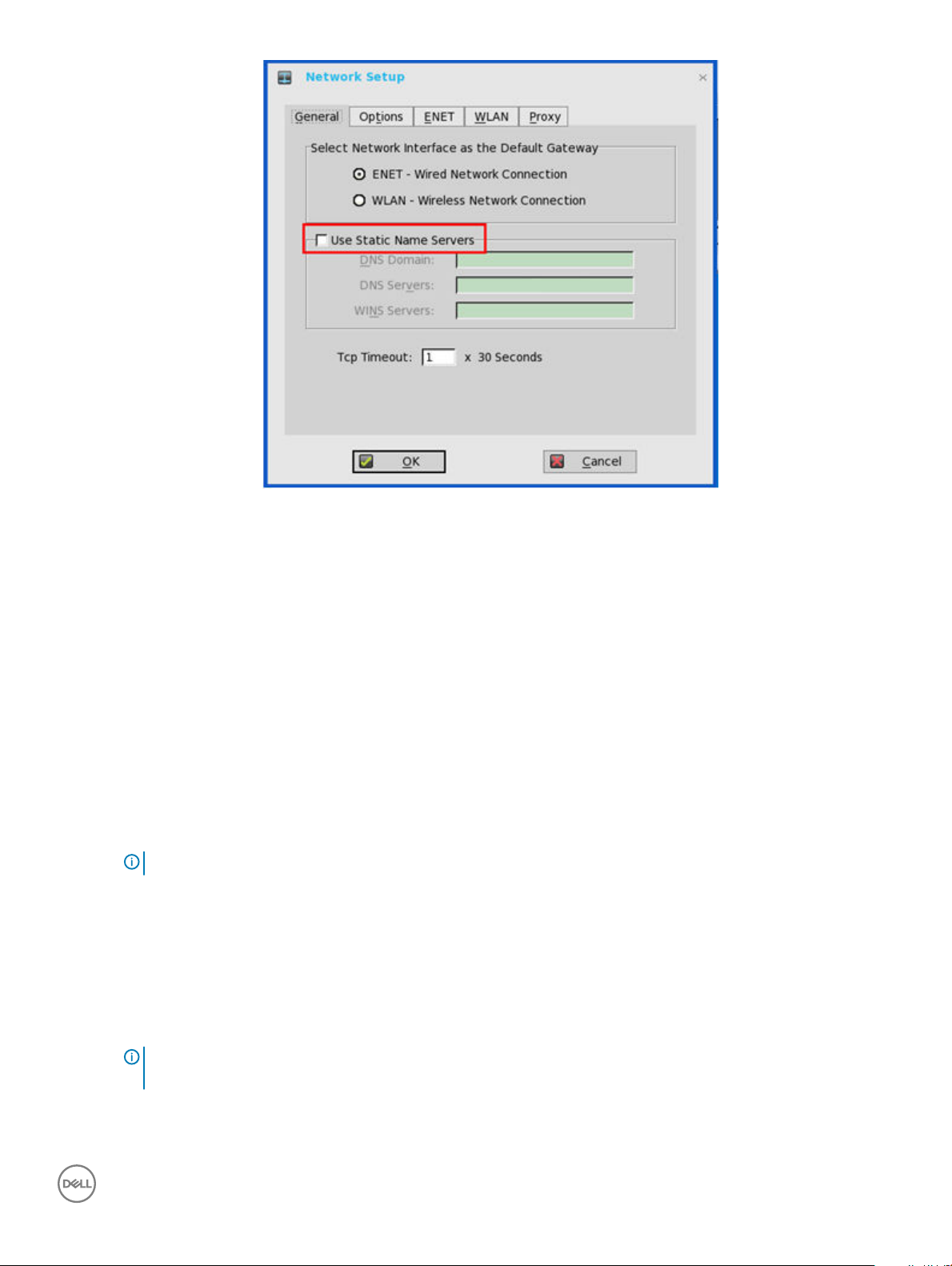
Figure 7. Network setup
2 Click the General tab and use the following guidelines:
a To set the default gateway, select the type of network interface from the available options.
1 Single Network support— Either wireless or wired network is connected.
• ENET — Click this option, if you want set up the Ethernet Wired Network Connection.
• WLAN — Click this option, if you want set up the Wireless Network Connection.
• If the user use wireless network after selecting ENET connection or wired network after selecting WLAN connection,
then the system log "WLAN: set default gateway xx.xx.xx.xx" for rst case and "ENET: set default gateway xx.xx.xx.xx"
for second case are printed to ensure that the UI setting reects the actual usage.
• Use Static Name Servers— By default, this check box is not selected, and thin client fetches the server IP address
from DHCP. Select this check box to manually assign static IP addresses. If name servers are changed using GUI, INI or
link down/ up, then the details are displayed in Event Logs. In dynamic mode, the DNS/WINS can be merged from
Ethernet and Wireless, if network is not working.
2 Dual Network support — Both wireless and wired networks are connected. The default gateway is determined by the UI
settings.
NOTE
: The UI will not be changed automatically.
b Enter the URL address of the DNS Domain in the DNS Domain box.
c Enter the IP address of the DNS Server in the DNS Server box.
Use of DNS is optional. DNS allows you to specify remote systems by their host names rather than IP addresses. If a specic IP
address (instead of a name) is entered for a connection, it is used to make the connection. Enter the DNS Domain and the
network address of an available DNS Server. The function of the DNS Domain entry is to provide a default sux to be used in
name resolution. The values for these two boxes may be supplied by a DHCP server. If the DHCP server supplies these values,
they replace any locally congured values. If the DHCP server does not supply these values, the locally congured values will be
used.
: You can enter upto 16 DNS Server addresses, separated by a semicolon, comma, or space. The rst address is
NOTE
for the primary DNS server and the rest are secondary DNS servers or backup DNS servers.
d Enter the IP address of the WINS Server in the WINS Server box.
Use of WINS is optional. Enter the network address of an available WINS name server. WINS allows you to specify remote
systems by their host names rather than IP addresses. If a specic IP address (instead of a name) is entered for a connection, it
Conguring
the connectivity 25
Page 26
is used to make the connection. These entries can be supplied through DHCP, if DHCP is used. DNS and WINS provide
essentially the same function, name resolution. If both DNS and WINS are available, the zero client attempts to resolve the name
using DNS rst and then WINS.
You can enter two WINS Server addresses (primary and secondary), separated by a semicolon, comma, or space.
e Enter the digit multiplier of 30 seconds in the TCP Timeout box to set the timeout value of a TCP connection. The value must
be 1 or 2 which means the connection timeout value is from 1x30= 30 seconds to 2x30= 60 seconds. If the data for connecting
to the server is not acknowledged and the connection is time out, setting the timeout period retransmits the sent data and again
tries to connect to the server till the connection is established.
3 Click OK to save the settings.
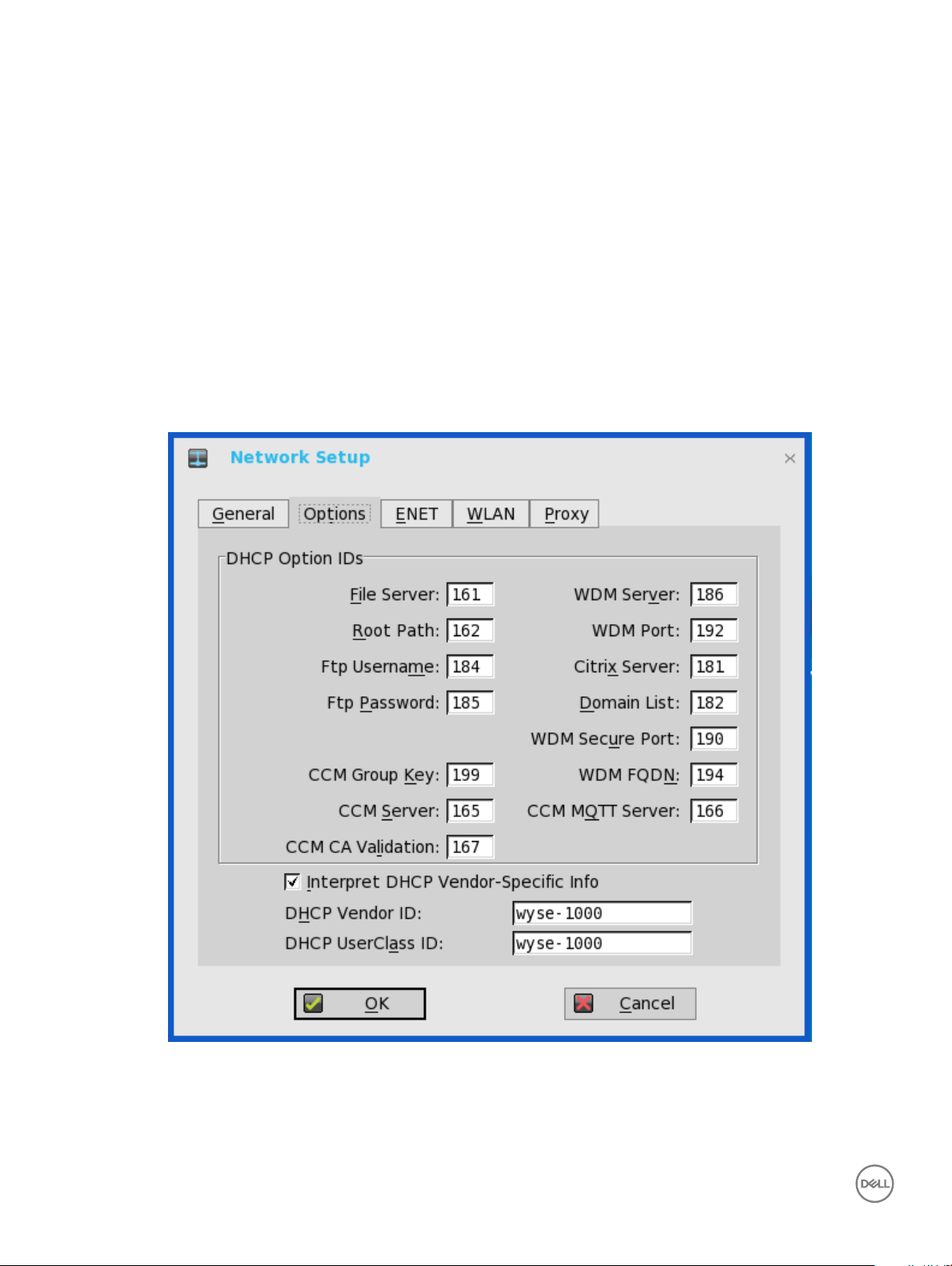
Conguring the DHCP options settings
To congure the Option settings :
1 From the oating bar menu, click the System Setup , and then click Network Setup.
The Network Setup dialog box is displayed.
2 Click the Options tab, and use the following guidelines:
Figure 8. Network Setup
a DHCP Option IDs — Enter the supported DHCP options; each value can only be used once and must be between 128 and
254). For information on DHCP options, see Using DHCP options
Conguring the connectivity
26
Page 27
b Interpret DHCP Vendor-Specic Info — Select this check box for automatic interpretation of the vendor information.
c DHCP Vendor ID — Shows the DHCP Vendor ID when the dynamically allocated over DHCP/ BOOTP option is selected.
d DHCP UserClass ID — Shows the DHCP UserClass ID when the dynamically allocated over DHCP/BOOTP option is selected.
3 Click OK to save the settings.
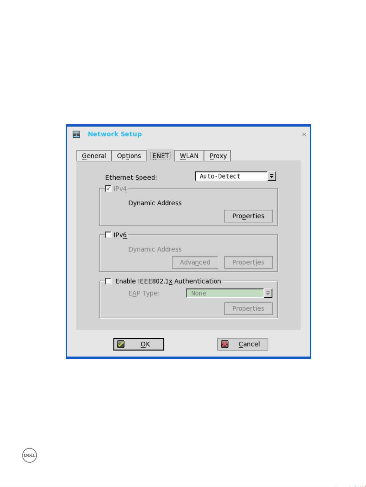
Conguring the ENET settings
To congure the ENET settings:
1 From the oating bar menu, click System Setup, and then click Network Setup.
The Network Setup dialog box is displayed.
2 Click the ENET tab, and use the following guidelines:
Figure 9. ENET settings
a Ethernet Speed — Normally the default (Auto-Detect) should be selected, but another selection can be made if automatic
negotiation is not supported by your network equipment. Selections include Auto-Detect, 10 MB Half-Duplex, 10 MB Full-
Duplex, 100 MB Half-Duplex, 100 MB Full-Duplex, and 1 GB Full-Duplex.
The 10 MB Full-Duplex option can be selected locally at the device, however, this mode may need to be negotiated through
AutoDetect.
b The IPV4 check box is selected by default. Click Properties to set various options supported by IPV4.
Conguring
the connectivity 27
Page 28

• Dynamically allocated over DHCP/BOOTP — Selecting this option enables your thin client to automatically receive
information from the DHCP server. The network administrator must congure the DHCP server using DHCP options to
provide information. Any value provided by the DHCP server replaces any value entered locally on the Options tab, however,
locally entered values are used if the DHCP server fails to provide replacement values.
• Statically specied IP Address — Select this option to manual enter the IP Address, Subnet Mask and Default Gateway:
– IP Address — Must be a valid network address in the server environment. The network administrator must provide this
information.
– Subnet Mask — Enter the value of the subnet mask. A subnet mask is used to gain access to machines on other
subnets. The subnet mask is used to dierentiate the location of other IP addresses with two choices: same subnet or
other subnet. If the location is other subnet, messages sent to that address must be sent through the Default Gateway,
whether specied through local conguration or through DHCP. The network administrator must provide this value.
– Default Gateway — Use of gateways is optional. Gateways are used to interconnect multiple networks (routing or
delivering IP packets between them). The default gateway is used for accessing the internet or an intranet with multiple
subnets. If no gateway is specied, the thin client can only address other systems on the same subnet. Enter the address
of the router that connects the thin client to the internet. The address must exist on the same subnet as the thin client
as dened by the IP address and the subnet mask. If DHCP is used, the address can be supplied through DHCP.
c Select the IPV6 check box, and then click Advanced to select various IPV6 supported setting options from the available check
boxes.
The following check boxes are displayed in the IPv6 Advanced Settings dialog box:
• Allow IPv4 to be disabled when IPv6 is enabled
• Prefer IPv4 over IPv6 when both are available
• Disable Stateless Address Auto conguration (SLAAC)
• Disable Duplicate Address Detection (DAD)
• Disable ICMPv6 Echo Reply
• Disable ICMPv6 Redirect Support
• Use Standard DHCPv6 Timers
Click properties and use the following guidelines:
• Wait DHCP — Selecting this option enables your thin client to wait for IPV6 DHCP before the sign-in, if not selected the
system will only wait for IPV4 DHCP if enabled.
• Dynamically allocated over DHCP/BOOTP — Selecting this option enables your thin client to automatically receive
information from the DHCP server. The network administrator must congure the DHCP server (using DHCP options) to
provide information. Any value provided by the DHCP server replaces any value entered locally on the Options tab, however,
locally entered values are used if the DHCP server fails to provide replacement values.
• Statically specied IP Address — Select this option to manually enter the IP Address, Subnet Mask and Default Gateway.
– IP Address — Must be a valid network address in the server environment. The network administrator must provide this
information.
Subnet Mask — Enter the value of the subnet mask. For more information, see various options supported by IPV4 in
–
this section.
– Default Gateway — Use of gateways is optional. For more information, see various options supported by IPV4 in this
section.
• DNS Servers — Use of DNS is optional. DNS allows you to specify remote systems by their host names rather than IP
addresses. If a specic IP address (instead of a name) is entered for a connection, it rather than DNS is used to make the
connection. Enter the network address of an available DNS Server. The value for this box may be supplied by a DHCP server.
If the DHCP server supplies this value, it replaces any locally congured value. If the DHCP server does not supply this value,
the locally congured value is used.
d Select the check box to enable IEEE802.1x authentication.
Conguring the connectivity
28
Page 29

EAP Type — If you have enabled the Enable IEEEE 802.1x authentication check box, select the EAP Type option you want
(TLS, LEAP, PEAP or FAST).
• TLS — If you select the TLS option, click Properties to open and congure the Authentication Properties dialog box.
– Select the Validate Server Certicate check box because it is mandatory to validate your server certicate.
NOTE:
The CA certicate must be installed on the thin client. Also note that the server certicate text eld supports
a maximum of approximately 255 characters, and supports multiple server names.
– If you select the Connect to these servers check box, the box is enabled where you can enter the IP address of server.
– Click Browse to nd and select the Client Certicate le and Private Key le you want.
NOTE: Make sure you select PFX le only.
– From the Authenticate drop-down list, select either User Authentication or Machine Authentication based on your
choice.
The following kinds of server names are supported — all examples are based on Cert Common name
company.wyse.com
◦ *.wyse.com
◦ *wyse.com
◦ *.com
NOTE
:
Using only the FQDN, that is company.wyse.com does not work. You must use one of the options (note that
*.wyse.com is the most common option as multiple authentication servers may exist): servername.wyse.com
• LEAP — If you select the LEAP option, click Properties to open and congure the Authentication Properties dialog box.
Be sure to use the correct username and password for authentication. The maximum length for the username or the
password is 31 characters.
• PEAP — If you select the PEAP option, click Properties to open and congure the Authentication Properties dialog box.
Be sure to select either EAP_GTC or EAP_MSCHAPv2, and then use the correct username, password and domain. Validate
Server Certicate is optional.
• FAST—If you select the FAST option, click Properties to open and congure the Authentication Properties dialog box. Be
sure to select either EAP_GTC or EAP_MSCHAPv2, and then use the correct username, password and domain. Validate
Server Certicate is optional.
From ThinOS Lite 2.3, EAP-FAST authentication is supported. During the initial connection, when there is a request for a
Tunnel PAC from the authenticator, the PAC is used to complete the authentication. Therefore, the rst time connection
always fails and the following connections succeed. Only automatic PAC provisioning is supported. The user/machine PAC
provisioning generated with Cisco EAP-FAST utility is not supported.
Conguring EAP-GTC and EAP-MSCHAPV2
• To congure EAP-GTC, enter the username only. The password or PIN is required when authenticating.
• To congure EAP-MSCHAPv2, enter the username, password and domain.
IMPORTANT
blank.
: The domain\username in the username box is supported, but you must leave the domain box
The CA certicate must be installed on the thin client and the server certicate is forced to be validated. When EAPMSCCHAPV2 is selected as EAP type in the Authentication Properties dialog box for PEAP or FAST authentication, an
option to hide the domain is available for selection. Username and Password boxes are available for use, but the Domain text
box is disabled.
Conguring
the connectivity 29
Page 30
When EAP-MSCHAPV2 is selected as EAP type in the Authentication Properties dialog box for PEAP or FAST
authentication, a check box to enable Single Sign-On feature is available for selection.
3 Click OK to save the settings.
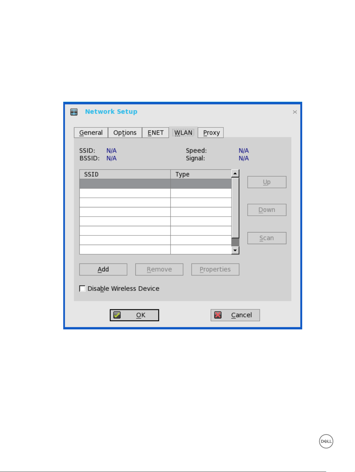
Conguring the WLAN settings
1 From the oating bar menu, click System Setup, and then click Network Setup.
The Network Setup dialog box is displayed.
2 Click the WLAN tab, and use the following guidelines:
Figure 10. WLAN settings
a Add— Use this option to add and congure a new SSID connection.
You can congure the SSID connection from the available security type options.
Conguring the connectivity
30
Page 31

b After you congure the SSID connection, the added SSID connection is listed on the page of the WLAN tab.
• Remove — Use this option, if you want to remove a SSID connection by selecting the SSID connection from the list.
• Properties — Use this option to view and congure the authentication properties of a SSID connection that is displayed in
the list. From the ThinOS Lite 2.3 release, a new EAP type named EAP-Fast is added in the EAP type drop-down list. During
the initial connection, when there is a request for a Tunnel PAC from the authenticator, the PAC is used to complete the
authentication. Therefore, the rst time connection always fails and the following connections succeed.
Only automatic PAC provisioning is supported from 2.3 release. The user/machine PAC provisioning generated with Cisco EAPFAST utility is not supported.
Conguring
the connectivity 31
Page 32

If you select EAP type as EAP-Fast, then EAP-MSCHAPV2 and EAP-GTC options are listed in the EAP type drop-down list in
the Authentication Properties dialog box (2nd authentication method supports MSCHAPv2/GTC only for EAP-FAST).
c Select the Disable Wireless Device check box, if you want to disable a wireless device.
• Always: Click this radio button if you want to disable the wireless device at all times.
• EnetUp: Click this radio button if you want to disable the wireless device whenever the wired network is connected.
3 Click OK to save the settings.
IMPORTANT
take eect immediately. For example, ThinOS Lite connects to the new wireless SSID immediately without reboot. However
for ARM platforms—Wyse 3010 zero client, and Wyse 3020 zero client—the disable/enable wireless requires reboot.
: From ThinOS Lite version 2.5, device reboot is not required to change the network settings. All the changes
Conguring the proxy settings
The network Proxy tab is added to support Wyse Management Suite, HDX Flash Redirection and Real Time Multimedia Engine (RTME).
32
Conguring the connectivity
Page 33

Figure 11. Network Setup
Supported Protocols
• For HDX FR, HTTP and HTTPS protocols are supported.
– If both are congured, the HDX FR works with HTTPS proxy.
– User credential pass through is possible with $UN/$PW.
• For WMS, HTTP, HTTPS and Socks5 (recommended) protocols are supported.
• For RTME, HTTP and HTTPS protocols are supported.
1 From the desktop menu, click System Setup, and then click Network Setup.
The Network Setup dialog box is displayed.
2 Click the Proxy tab, and use the following guidelines:
a Enter the HTTP proxy port number or HTTPS proxy port number, Username and Password in the respective elds. However,
Credential pass through ($UN/$PW) is not recommended because it starts before user sign on.
Wyse Management Suite uses both HTTP/HTTPS and MQTT protocols to communicate with CCM/MQTT server. However, the
HTTP proxy cannot redirect TCP packages to MQTT server which requires a Socks5 proxy server. If there is only HTTP server
available, then the real-time command that requires MQTT will not work.
HTTP/HTTPS proxy default port is 808, and SOCK5 proxy default port is 1080.
Conguring
the connectivity 33
Page 34

b Select the Use the rst proxy server for all protocols check box to allow all the protocols to use the same server in HTTP Proxy
elds. Both HTTP and HTTPS proxy use the same host and port, and Socks5 proxy agent uses HTTP host with default Socks 5
port (1080).
c If SOCKS5 proxy is congured, then Wyse Management Suite proxy uses the SOCKS5 only. If SOCKS5 is not congured, then
Wyse Management Suite proxy searches for alternative protocols, for example, HTTP in the conguration.
d Specify the supported applications as Wyse Management Suite, FR, and RTME in the Apply proxy server on eld.
3 Click OK to save the settings.
User Scenarios
1 Congure correct proxy server host and port.
2 Congure the user credentials according to the proxy server settings.
3 On system restart, the client checks in to the Wyse Management Suite server through Socks5 proxy server.
4 MQTT connection is established through Socks5 proxy server.
5 Real-time commands work ne through Socks5 proxy server.
6 Connect to the Citrix desktop, congure proxy in internet options of the browser, and then playback HDX FR through the HTTP/
HTTPS proxy authentication.
Conguring the remote connections
Use the Remote Connections dialog box to congure zero client remote connections for Citrix XenDesktop broker setup, visual options,
and general connection settings.
Use the following options to congure the remote congurations:
• Conguring the Broker Setup
• Conguring the Visual Settings
• Conguring the General Options
• Conguring the Authentication Settings
Conguring the Citrix broker setup
To congure the broker setup, do the following:
1 From the oating bar menu, click the System Setup , and then click Remote Connections.
The Remote Connections dialog box is displayed.
34
Conguring the connectivity
Page 35

Figure 12. Broker setup
2 Select the StoreFront Style check box to enable the StoreFront style.
3 Broker Server— Enter the IP address / Hostname / FQDN of the broker server.
4 Select the Enable automatic reconnection at logon check box to enable automatic re-connection at logon.
NOTE
: If you enable the automatic re-connection, you are able to select from the re-connection options. Click either of the
options where you can connect to disconnected sessions only or both active and disconnected sessions.
5 Select the Enable automatic reconnection from the button menu check box to enable automatic reconnection from the button
menu. You can select any of the following options:
• Connect to disconnected sessions only.
• Connect to active and disconnected sessions.
6 Account Self-Service Server— Enter the IP address of the Account Self-service Server.
7 XenApp — Use this option if you want to set default settings to XenApp.
8 XenDesktop— Use this option if you want to set default settings as XenDesktop.
9 Click OK to save the settings.
Conguring the visual settings
To congure the visual settings:
1 From the oating bar menu, click the System Setup , and then click Remote Connections.
The Remote Connections dialog box is displayed.
2 Click Visual Experience tab and use the following guidelines:
Conguring
the connectivity 35
Page 36

NOTE: The Visual Experience tab is grayed out, if the StoreFront Style check box is selected for a Citrix Broker Server
entered in the Broker Setup tab.
a Select the check box to enable Zero Toolbar activation in left pane.
• Select the button if you want to enable Zero Toolbar activation in left pane when you pause a mouse on the screen.
• Select the button if you want to enable Zero Toolbar activation in left pane only after clicking.
b Select the check box to disable hotkey to show toolbar.
c Select the check box to always disable toolbar when you have one session available.
d Select the check box to disable the Home Icon.
3 Click OK to save the settings.
Conguring the general options
To Congure the Remote Congurations to General Options:
1 From the oating bar menu, click the System Setup , and then click Remote Connections.
The Remote Connections dialog box is displayed.
36 Conguring the connectivity
Page 37

Figure 13. General options
2 Click General Options and use the following guidelines:
a Click the available options to select the action after you exit all open desktops. The available options are None, Sign-o
automatically, Shut down the system automatically and Restart the system automatically.
NOTE
: By default, None is selected and the zero client automatically returns to the terminal desktop.
b Default Sign-on Username— Enter the Default user name.
c Default Sign-on password— Enter the Default password.
d Default Sign-on Domain— Enter the Default Domain.
: If you enter all three Default Sign-on credentials (Username, Password and Domain), you are automatically
NOTE
logged on to your desktop upon system start.
Conguring the connectivity 37
Page 38

Conguring the authentication settings
To congure the authentication settings:
1 From the oating bar menu, click the System Setup , and then click Remote Connections.
The Remote Connections dialog box is displayed.
Figure 14. Authentication settings
2 Click the Authentication tab, and use the following guidelines:
a Authentication type— Click the button to select the Authentication type.
• Imprivata — OneSign Virtual Desktop Access provides a seamless authentication experience and can be combined with
single sign-on for No Click Access to desktops and applications in a virtual desktop environment.
Conguring the connectivity
38
Page 39

To congure the OneSign Server, enter either https://ip or https://FQDN values, reboot the client to display the logon dialog
box, and then enter credentials to open the VDI broker dialog box for logon use. You can also set this feature in your INI le,
seeParameters for a xen.ini File in this guide.
For details on Deployment in an Imprivata OneSign ProveID Environment, see Knowledge Base Solution #23254. Go to
www.dell.com/wyse/knowledgebase and search for 23254.
The following OneSign features/actions are supported:
– Client and Broker Authentication
◦ Citrix XenApp
◦ Citrix XenDesktop
– Kiosk Mode
– Fast User Switching
– Non-OneSign user VDI access
– Hotkey Disconnect
– Proximity card reader redirection
– Guided Question and Answer login
– Authenticate w/Password
– Authenticate w/Password + Password Change
– Authenticate w/Password + Password Change | New Password is Invalid
– Authenticate w/Proximity Card + Password
– Authenticate w/Proximity Card + Pin
– Authenticate w/Proximity Card + Pin | Pin not enrolled
– Authenticate w/Proximity Card Alone | Retrieve Password
– Retrieve User Identity Password
– Reset User Identity Password
– Update User Identity Password
– Enroll Proximity Card
– Lock/Unlock Terminal with Proximity CardLock/Unlock Terminal with Proximity Card
• Caradigm — Caradigm Single Sign-on and Context Management is the product of the Caradigm Company which provides
Single Sign-on and Context Management Services.
a SSO & CM Server— Enter the IP addresses of the Single Sign-On (SSO) and Context Management (CM) Servers.
b Default Group Name —Type the name of the default group in the Default Group Name box.
c Enable logo remote desktop
– Select the check-box to log o the current user from the session before system sign-o.
– Clear the selection to disconnect from the session.
• SECUREMATRIX — SECUREMATRIX enhances the security of enterprise and cloud-based applications while providing
seamless end user experience for a one-time password (OTP) that can be used for authentication with desktops, Windows,
VPNs, intranets, extranets, web servers, e-commerce and other network resources.
To congure the SECUREMATRIX Server, enter either https://ip or https://FQDN values, reboot the client to display the
log on dialog box, and then enter credentials to open the VDI broker dialog box for logon use. You can also set this feature in
your INI le, see the INI section in this guide. For details on SECUREMATRIX, see SECUREMATRIX documentation.
• HealthCast Single Sign-On (SSO)—HealthCast Single Sign-On (SSO) solution is designed to improve user convenience,
streamline workow, and strengthen security compliance in demanding environments. The same proximity cards used for
physical access are used to tap-in and tap-out of unique user sessions and to tap-over any sessions unintentionally left open
Conguring
the connectivity 39
Page 40

on the ThinOS Lite devices. Typically, you must type in your password only one time each day and use your proximity cards to
streamline workow and save time as they move between shared computers securely. Also, proximity cards can be secured
with a PIN, if congured by the organization. The HealthCast SSO solution also supports user self-service password reset so
that you can reset your own passwords without the need to call the help desk.
• OneSign Server— Enter the IP Address of the OneSign Server.
3 Click OK to save the settings.
Conguring objects on Imprivata server
This version of ThinOS Lite supports Imprivata WebAPI version 5. This version supports Conguration objects to control dierent aspects
of client behavior. User can experience the Imprivata WebAPI feature on OneSign server 4.9 or later versions.
This version supports conguration objects to control dierent aspects of the client behavior.
Use the following guidelines to congure the objects on Imprivata Server:
1 Conguring the General conguration object
a On the Imprivata server, click Computer policy, and then click General tab.
b Select the check box to allow users to shut down and restart workstation from lock screen.
NOTE: Display shutdown button and restarts commands to the user on the OneSign GINA.
The following conguration objects are supported on Imprivata server:
• Shutdown Allow
– If you enable this feature by selecting the check box, the shutdown and restart icon is shown in ThinOS Lite login and
locked windows.
40
Conguring the connectivity
Page 41

Figure 15. Imprivata
– If you clear the check box, the shutdown and restart icon is grayed out.
• FailedOneSignAuth Allow—
Only yes or no options are supported. Non-OneSign user can log in to the Broker by clicking No radio button.
• Logging Allow
– OneSign logs could output on ThinOS Lite with this feature. An INI conguration is needed correspondingly.
– Loglevel=0/1/2/3. The default value is 0. If set to 0, logs are not displayed.
• Display name format — Account name can be shown correctly with dierent formats in pop-up notications.
2 Conguring the Walkway conguration object
On the Imprivata server, click Computer policy, and then click the Walk Away tab.
• Key mouse inactivity enabled and behavior — The check box in addition to keyboard and mouse inactivity is not supported.
• Passive proximity cards
– If you want to use proximity card to lock the computer, select the Tap to lock check box.
– If you want to lock the computer and log in as a dierent user. select the Switch users check box.
– INI parameter isTapToLock=0/1/2.
• Lock warning enabled and type— The three types that are supported are: none, notication balloon and Screensaver.
– ◦ None — No warning messages are displayed.
◦ Notication balloon— ThinOS Lite displays a notication window.
Conguring
the connectivity 41
Page 42

◦ Screensaver— Hide the display contents before the workstation locks.
• Warning message— The message can be customized.
• Lock Screen type —Only obscure type is supported.
• Hot key to lock workstation or log o user— ThinOS Lite can support following keys:
“F1 ~ F12”, "BKSP", “DEL”, “DOWN”, “END”, “ENTER”, “ESC”, “HOME”, “INS”, “LALT”, “LEFT”, “LCONTROL”, “NUMLOCK”,
“PGDN”, “PGUP”, “RCONTROL”, “RIGHT”, RTALT”, “SPACE”, “TAB”, “UP”, “a~z”, “A~Z”, “0~9” and modier “+”, “%”, “^” (Shift, Alt
and Control)
• Suspend action — The server conguration controls this feature on ThinOS Lite. Therefore a new INI is added—
SuspendAction=0/1; 0 means lock, 1 means signo.
3 Conguring the SSPR Conguration Object
The SSPR conguration object controls the Self-Service Password Reset behavior for a user. The enabled attribute species whether
the user is allowed to reset their password as part of emergency access. The mandatory attribute species whether the user must
reset their password as part of emergency access.
4 Conguring the RFIDeas conguration object
The RFIDeas conguration object controls the behavior of the RFIDeas readers. The conguration can be congured by two ways, the
computer policy of OneSign server and ThinOS Lite INI.
5 Conguring the Custom background conguration object
On the Imprivata server, click Computer policy, and then click the Customization tab.
Custom background image impacts the wallpaper of ThinOS Lite sign-on screen.
Figure 16. Background
6 Conguring the Co-Branding conguration object
On the Imprivata server, click Computer policy , and then click Customization.
42
Conguring the connectivity
Page 43

Figure 17. Login screen appearance
Logo image impacts all the dialog boxes in ThinOS Lite with raw logo.
7 Conguring the SSPR Customization Conguration object
• The text displayed in sign-on UI and lock window can be customized.
• The largest size supported by ThinOS Lite is 17 characters.
ThinOS Lite UI:
Figure 18. Imprivata OneSign
8 Password Self-Services force enrollment feature
Conguring
the connectivity 43
Page 44

Selecting this check box allows you to reset the primary authentication password.
Figure 19. Security question
INI conguration for Imprivata OneSign Server
A new INI parameter is added to the OneSignServer=AutoAccess=command. The new value is AutoAccess=Local. When
AutoAccessis set to local, the ThinOS Lite ignores the brokers that are set on the Imprivata OneSign Appliance and starts the broker/
connections which are dened in xen.ini or local dened on the client. You can start the ThinOS Lite connections while supporting Imprivata
user authentication.
Proximity card enrollment
1 Tap the proximity card. The card enrollment page is displayed.
Figure 20. Enroll proximity card
2 Enter the credentials and then click OK.
Conguring the connectivity
44
Page 45

Figure 21. Conrm identity
Proximity card is enrolled successfully.
Figure 22. Proximity card success message
Imprivata bio-metric single sign-on
Imprivata WebAPI is updated to version 5. The key feature of this version is the Fingerprint identication feature. This feature is highly
reliable, and cannot be easily replicated, altered, or misappropriated.
The prerequisites of OneSign server are:
• Imprivata v4.9 or later appliance version is needed that supports the WebAPI v5 and later versions.
• Fingerprint identication license is required.
Conguring
the connectivity 45
Page 46

Figure 23. Licensed options
•
Figure 24. Desktop access authentication
Fingerprint authentication must be enabled in OneSign user policy
Following are the features of Imprivata Bio-metric Single Sign-On:
1 Supported protocol is ICA.
2 Required Fingerprint reader devices are:
a ET710 (PID 147e VID 2016)
b ET700 (PID 147e VID 3001)
3 Fingerprint authentication to sign-on/unlock for ThinOS Lite devices. For more information, see Signing in or Unlocking ThinOS Lite
Devices using Fingerprint Authentication.
4 Fingerprint authentication to unlock the virtual desktop. For more information, see Unlocking Virtual Desktop using Fingerprint
Authentication
5 ThinOS Lite supports the following Fingerprint authentication combinations:
Table 4. Fingerprint authentication combinations
Primary Factors Secondary Factors
Fingerprint No second factor
Password
46 Conguring the connectivity
Page 47

Primary Factors Secondary Factors
Imprivata PIN
Proximity Card Fingerprint
Fingerprint or Password
Fingerprint or Imprivata PIN
Signing in or unlocking ThinOS Lite devices using ngerprint authentication
To sign-on/unlock the ThinOS Lite devices using ngerprint authentication, do the following:
1 Congure the OneSign server on ThinOS Lite, and then plug-in the ngerprint reader device.
The ThinOS Lite Fingerprint window is displayed automatically after OneSign server is initialized.
Figure 25. OneSign
2 Fingerprint authentication works on the ThinOS Lite unlock window.
Conguring
the connectivity 47
Page 48

Figure 26. Verifying administrator
Unlocking virtual desktop using ngerprint authentication
To unlock the virtual desktop using ngerprint authentication, do the following:
1 Enable the Imprivata Virtual Channel.
48
Conguring the connectivity
Page 49

Figure 27. Global connection settings
2 When you lock the virtual desktop in the session, the Fingerprint window is displayed automatically
Conguring
the connectivity 49
Page 50

Figure 28. Verifying administrator
3 You can manage Fingerprints on virtual desktop. This requires OneSign agent v4.9. To manage Fingerprints, do the following:
a Right-click the OneSign agent icon in System tray.
b Click Manage Fingerprints, and enter the correct credentials in the displayed window to manage your Fingerprints.
50
Conguring the connectivity
Page 51

Figure 29. Manage ngerprints
Conguring the Caradigm Vault server
To congure the Caradigm Vault server on ThinOS Lite, do the following:
1 From the oating bar menu, click the System Setup , and then click Remote Connections.
The Remote Connections dialog box is displayed.
2 Click the Authentication tab, enter the IP address of the SSO & CM Server and then click OK.
Conguring
the connectivity 51
Page 52

Figure 30. Remote Connections
3 On the Caradigm Vault Server, use the following guidelines:
• Ensure that the Enroll unenrolled badges option is checked.
• Make sure that all Badge ID mapping entries are deleted.
Conguring the connectivity
52
Page 53

Figure 31. Tap server
4 Click SSO&CM > Advanced Congurations , and use the following guidelines:
Figure 32. Enable proximity server
a Ensure that the Enable Proximity Support check box is selected.
b Ensure that the Enable way2care check box is selected.
5 To prepare a certicate to the Caradigm Vault Server, use the following guidelines:
The Caradigm Vault Server uses the certicate to validate the connection between the Tap Server and the zero client.
a To raise a request for the certicate:
• The certicate should be issued by your Certicate Authority.
• Prepare the certicate in two formats:
– PFX format which has a private key.
– The other is PEM format which is text-based, Base64-encoded DER le. For Example, Caradigm.cer, Caradigm.pfx.
b To import a certicate to the zero client, use either of the following two options:
• Click System Setup > System tools > Certicates to import certicates from USB storage or le server.
• Use INI le to import certicate.
AddCertificate=client_cert.pfx password=passpass
c To add a certicate to Vault server:
Conguring
the connectivity 53
Page 54

Figure 33. Thin client certicates
Use the zero client Certicates page to add certicates for the zero client devices. The certicate must be a text in PEM
format, that is, a text-based Base64-encoded DER le.
• Open the DER cert le on Notepad.
• Log in to the Vault Server Admin Console, and then click Appliance > zero client Certicates.
• Copy the Notepad text to the Vault server
Conguration on VDI Server and Desktops
Caradigm solution of ThinOS Lite supports the multi-types of VDI server such as Citrix XenApp 6.5, Citrix XenDesktop 5.6 and Citrix
XenDesktop 7.6.
To congure the VDI server and desktop:
• Install the Caradigm desktop components in the servers and desktops.
• Indicate vault server IP, and then provide a valid security token.
• Add following lines to Service section of the\programdata\sentillion\vergence\Authenticator.ini conguration le.
TapServerIdentification=True
RemotePromptForPassword=Badge
Introduction to HealthCast
HealthCast Single Sign-On (SSO) solution is designed to improve user convenience, streamline workow, and strengthen security
compliance in demanding environments. The same proximity cards used for physical access are used to tap-in and tap-out of unique user
sessions and to tap-over any sessions unintentionally left open on the ThinOS Lite devices. Typically, you must type in your password only
one time each day and use your proximity cards to streamline workow and save time as they move between shared computers securely.
Also, proximity cards can be secured with a PIN, if congured by the organization. The HealthCast SSO solution also supports user selfservice password reset so that you can reset your own passwords without the need to call the help desk.
: HealthCast SSO Solution on ThinOS Lite is a client-server solution. ThinOS Lite provides the client-side functionality, but
NOTE
you must also install and congure the HealthCast Server components on a server system in order for the solution to work
properly. Contact HealthCast on HealthCast website for one or more server installation executables, server requirements, and
conguration information.
Conguring HealthCast on ThinOS Lite
HealthCast Web API Server is integrated with ThinOS Lite release to implement the HealthCast SSO solution. To use the HealthCast SSO
solution, ThinOS Lite must be congured to use the HealthCast Web API Server. You can do this by using the INI le (wnos.ini), or using
the ThinOS Lite UI. Dell recommends you to use the INI le for large deployments.
ThinOS Lite UI conguration
• To use the HealthCast Web API, congure the HealthCast settings on the zero client side. To congure, do the following:
a From the desktop menu, click System Setup , and then click Remote Connections.
Conguring the connectivity
54
Page 55

The Remote Connections dialog box is displayed.
b Click the Authentication tab, and then click HealthCast.
Figure 34. Remote connections
c Enter the HealthCast server details in the box provided.
d To import the client certicate, click Browse, and select the appropriate certicate you want to use.
Conguring
the connectivity 55
Page 56

Figure 35. Certicates browser
e Click OK to save the settings.
INI conguration
To congure using INI parameters, add the following INI parameters to your wnos.ini le:
• HealthCastServer— The server address and options needed for the client to connect to the HealthCast Web API Server.
HealthCastServer=<https address> SecurityMode=<default, full, warning, low> ClientCerticate=<cert-pfx-le-name>
For example: HealthCastServer=https://server1.example.com SecurityMode=full ClientCerticate=client-cert.pfx.
For more information on INI parameters, see INI parameters
HealthCast SSO features and functionality on ThinOS Lite
The following are the HealthCast SSO features and functionality on ThinOS Lite:
• Proximity card enrollment
– HealthCast supports user self-enrollment. Therefore, there is no need to bring the proximity card to a special registration station, or
for IT sta to be involved. Instead, you must only tap the disenrolled proximity card at a terminal and you can follow the easy
registration process. This is a one-time event after which you can use the card wherever HealthCast is installed.
Conguring the connectivity
56
Page 57

Figure 36. Proximity card enrollment
• Manual login and lock/unlock terminal
– If you do not have a card, or choose not to use your card, then you can manually log in using your user name and password.
Administrators can disable manual login, if they wish, so that users can sign on with their proximity cards. You can also lock or
unlock the terminal, if you have signed on with a manual login.
Figure 37. Manual login and lock/unlock terminal
• Proximity card login and lock/unlock terminal
– After the proximity card is registered, tap the card at a terminal to login.
Conguring
the connectivity 57
Page 58

Figure 38. Login
You can lock the session to secure it, but leave the remote session connected for fast access when you return. To do this, tap the
proximity card and the session is locked.
Figure 39. Lock terminal
To resume the session, tap the card again.
Conguring the connectivity
58
Page 59

• Walk away
– Terminals can be congured to lock or log o sessions that have been left open. The time that will elapse before automatic lock or
log o can be set by an administrator using the convenient web administration application.
• Tap-Over
– If a session is locked or left open, a second user can tap their own proximity card and this will disconnect the rst session and log
the second user into their own unique session.
• Forgotten card
– If you forget your card at home, you can receive a temporary card and register it for the day using the same easy registration
process mentioned above.
• Lost or stolen card
– If you report a card as lost or stolen, an administrator can immediately disable the card using the convenient web administration
application. This prevents anyone else from using it.
• Self-Service Password Reset (SSPR)
– If SSPR enabled by an administrator, you can register for SSPR and reset your passwords without calling the help desk.
Figure 40. SSPR enrollment
• Easy to use web-based administration tool
– Administrators can quickly and easily congure settings, manage proximity cards, and users using a web-based administration tool.
Conguring the central congurations
Use the Central Conguration dialog box to congure zero client central connection settings such as le server, optional WDM server
settings, and optional Cloud Client Manager.
Use the following options to congure the Central Congurations:
• Conguring the General Central Congurations.
• Conguring the WDA Settings
Conguring
the connectivity 59
Page 60

Conguring the general central congurations
To congure the General Central Congurations:
1 From the oating bar menu, click the System Setup , and then click Central Conguration.
The Central Conguration dialog box is displayed.
Figure 41. Central conguration
2 Click General tab and use the following guidelines:
File Servers/Path, Username and Password — IP address or host name of the le server that provides the system software and
update images. The address can be supplied through DHCP, if DHCP is used.
a File Servers/Path — Allows maximum of 127 characters for le server, and maximum of 127 characters for root path. The data
species part of the path to be used when the server is accessed. Multiple le servers/paths may be named, as long as all data
ts in the length limitation.
b Username — To log in to the le server. Use maximum of 31 characters.
c Password — To log in to the le server. Use maximum of 31 characters.
3 Click OK to save the settings.
Conguring the connectivity
60
Page 61

Conguring the Wyse Device Agent settings
Use this tab to congure the Wyse Device Manager (WDA) and Wyse Management Suite settings.
ThinOS Lite supports all the Wyse Management Suite Group Policy settings. To congure the Wyse Management Suite settings, do the
following:
1 From the desktop menu, click System Setup, and then click Central Conguration.
The Central Conguration dialog box is displayed.
2 Click WDA > WMS, and use the following guidelines:
Figure 42. Central
By default, the WMS option is selected. Wyse Management Suite service automatically runs after the client boot up.
If the rst discovery, for example, the Wyse Management Suite service is not successful, then it seeks for the next priority, for
example, WDM service. This continues until a discovery is successful. If all discoveries fail, then it is started again automatically after a
xed time—24 hours.
a Enable Wyse Management Suite (WMS)—Select the check box to enable the Wyse Management Suite to discover your thin
client.
b DNS SRV record—Select this check box if you want the thin client to obtain the Wyse Management Suite values through DNS
server, and then try to register into the Wyse Management Suite server. By default, the check box is selected. If the check box
selection is canceled, then the thin client cannot obtain the Wyse Management Suite values through DNS server.
To create DNS records in DNS server, use the following information:
# WMS server URL
DNS Record Type: DNS SRV
conguration
Conguring
the connectivity 61
Page 62

Record Name: _WMS_MGMT._TCP.<Domain>
Value Returned: WDMNG Server URL
Example: _WMS_MGMT._TCP.WDADEV.com
# MQTT Server URL
DNS Record Type: DNS SRV
Record Name: _WMS_MQTT._TCP.<Domain>
Value Returned: WMS Server URL
Example: _WMS_MQTT._TCP.WDADEV.com
# Group Token
DNS Record Type: DNS Text
Record Name: _WMS_GROUPTOKEN.<Domain>
Value Returned: Group Token (as String)
Example: _WMS_GROUPTOKEN .WDADEV.com
# CA Validation
DNS Record Type: DNS Text
Record Name: _WMS_CAVALIDATION.<Domain>
Value Returned: TRUE or FALSE (as String)
Example: _WMS_CAVALIDATION.WDADEV.com
c Group Registration Key—Enter the Group Registration Key as congured by your Wyse Management Suite administrator for
the desired group. To verify the key, click Validate Key.
A Group Registration Key is not required for the private Wyse Management Suite server. You can provide the Wyse Management
Suite server details to allow the device to check in to Wyse Management Suite. ThinOS Lite registers to a quarantine tenant in
Wyse Management Suite.
d Enable WMS Advanced Settings—Select this check box to enter the Wyse Management Suite server, MQTT server details,
and to enable the CA validation. By default, the MQTT server option is disabled. The MQTT server value is populated after the
ThinOS Lite device is checked in to the Wyse Management Suite.
NOTE
: If you enable the Wyse Management Suite, make sure that you have entered the Group Registration Key and
congured the Wyse Management Suite advanced settings.
For more information about using Wyse Management Suite to manage the ThinOS Lite devices, see the Wyse Management Suite v1.1
Administrator's Guide at Dell.com/manuals.
3 Click OK to save the settings.
Service checked in status is displayed in System Information tab.
To congure the WDM settings, do the following:
Conguring the connectivity
62
Page 63

Figure 43. General central conguration
1 Click WDM, and use the following guidelines:
2 WDM Servers—Enter the IP addresses or host names, if WDM is used. Locations can also be supplied through user proles, if user
INI proles are used.
3 DNS Name Record—(Dynamic Discovery) Allows devices to use the DNS host name lookup method to discover a WDM Server.
4 DHCP Inform—(Dynamic Discovery) Allows devices to use DHCP Inform to discover a WDM Server.
5 Enable Automatic Discovery After Missed Check-ins—Select the number of missed check-ins after which you want the auto
discovery options enabled.
6 Click OK to save the settings.
The Wyse Device Manager option can be disabled using the following INI parameters:
• WMSService=no
• Service=wdm disable=yes
• RapportDisable=yes
Conguring the VPN manager
The VPN Manager was included in ThinOS Lite 2.1 to manage VPN connections. A virtual private network (VPN) extends a private network
across a public network such as the Internet. It enables a computer or Wi-Fi-enabled device to send and receive data across shared or
public networks as if the devices are directly connected to the private network, while beneting from the functionality, security and
management policies of the private network.
To congure the VPN manager, do the following:
1 From the oating bar menu, click the System Setup , and then click VPN Manager.
The VPN Manager dialog box is displayed.
Conguring
the connectivity 63
Page 64

Figure 44. VPN manager
2 Click New tab to Create a new Connection.
The OpenConnect Property page is displayed.
• Session Name — Enter the name of the Session Name.
• VPN Server — Enter the IP address of the VPN Server.
• Login Username— Enter the Login Username.
• Password— Enter the password of the user.
• Select the check box to Auto-connect on system startup.
• Select the check box to Show progress in detail.
64
Conguring the connectivity
Page 65

Figure 45. OpenConnect property
3 Click Connect to connect to the VPN Manager.
4 Click Edit to edit the to the VPN Manager connections.
5 Click Delete to delete the VPN Manager.
Figure 46. Delete VPN manager
Conguring
the connectivity 65
Page 66

Conguring the connection broker
In a Virtual Desktop Infrastructure (VDI) environment, a connection broker is a software entity that allows you to connect to an available
desktop. The connection broker facilitates the VDI environment to securely and eciently manage the centrally hosted desktop
environments.
NOTE:
• Linux hosted desktop in the Citrix brokers is supported.
• Windows 10 desktop in multiple brokers is supported.
– Windows 10 desktop is supported in the Citrix brokers.
• ICA multicast feature is not supported from ThinOS Lite 2.4. However, the URL redirection works.
Conguring Citrix
Citrix oers a complete virtualization solution, where all applications and resources are deployed on a centralized server, and published to
remote devices. The Citrix Receiver client software installed on the thin client allows you to interact with the application GUI, while all of
the application processes are performed on the server.
5
This section provides information about how to congure a Citrix broker connection on your ThinOS Lite device, and other Citrix features
that you can congure on ThinOS Lite.
Conguring the Citrix broker setup
To congure the broker setup, do the following:
1 From the oating bar menu, click the System Setup , and then click Remote Connections.
The Remote Connections dialog box is displayed.
66 Conguring the connection broker
Page 67

Figure 47. Broker setup
2 Select the StoreFront Style check box to enable the StoreFront style.
3 Broker Server— Enter the IP address / Hostname / FQDN of the broker server.
4 Select the Enable automatic reconnection at logon check box to enable automatic re-connection at logon.
NOTE
: If you enable the automatic re-connection, you are able to select from the re-connection options. Click either of the
options where you can connect to disconnected sessions only or both active and disconnected sessions.
5 Select the Enable automatic reconnection from the button menu check box to enable automatic reconnection from the button
menu. You can select any of the following options:
• Connect to disconnected sessions only.
• Connect to active and disconnected sessions.
6 Account Self-Service Server— Enter the IP address of the Account Self-service Server.
7 XenApp — Use this option if you want to set default settings to XenApp.
8 XenDesktop— Use this option if you want to set default settings as XenDesktop.
9 Click OK to save the settings.
Citrix HDX RealTime Multimedia Engine—RTME
RTME 1.8 was a new feature introduced in ThinOS Lite 2.2. This is the Citrix HDX RealTime Optimization Pack 1.8 for Lync. In ThinOS Lite
2.3 release, the Citrix HDX RealTime Optimization Pack 2.0 (RTME 2.0) is supported. Citrix RTME 2.0 is introduced to support Microsoft
Skype for Business 2015 client/UI (only), in addition to RTME 1.8 supporting the Microsoft Lync 2010/2013 clients. From ThinOS Lite 2.4
release, RTME version is updated to a newer version 2.2– Citrix HDX RealTime Optimization Pack 2.2 for Microsoft Skype for Business
Conguring
the connection broker 67
Page 68

2016. This section provides information about supported platforms for RTME, installation of RTME package, Citrix remote Server/Desktop
host preparation, conguration on ThinOS Lite, and RTME status check and troubleshooting.
• Installing the RTME package on ThinOS Lite.
• Setting Up the RTME Connector.
• Verifying the RTME 1.8 Status.
• Verifying the RTME 2.2 Status.
Introduction
The Citrix HDX RealTime Optimization pack oers high-denition audio and video calls on Lync. In every ThinOS Lite release, the RTME
version may be updated to newer version and the latest RTME version co-exists with RTME 1.8 version in the corresponding release
packages. ThinOS Lite v2.5 supports RTME/RTOP version 2.3. However, you can still use RTME 2.2 package.
For more information about Citrix RTME 1.8 feature, go to docs.citrix.com/en-us/hdx-optimization/1-8/hdx-realtime-optimization-pack-
about.html.
For more information about Citrix RTME 2.3 feature, go to docs.citrix.com/en-us/hdx-optimization/current-release/whats-new.html.
For information on how to use Citrix RTME 1.8 feature, go to docs.citrix.com/en-us/hdx-optimization/1-8/hdx-realtime-optimization-pack-
troubleshooting.html
For information on how to use Citrix RTME 2.3 feature, go to docs.citrix.com/en-us/hdx-optimization/current-release/install.html..
.
Supported Environments
• Citrix environment: XenDesktop and XenApp 5.6/6.5/7.x
• Desktop with RTME connector 1.8 (Lync server and client version 2010 and 2013; Skype for Business client in Lync 2013 GUI is
supported).
• Desktop with RTME connector 2.2 (Skype for Business 2015 and 2016 is supported).
• Supported networks: LAN, WAN (VPN), wireless and so on.
• Supports calls between RTME clients or between RTME and standard Lync clients.
• Supports Microsoft Oce 365 or Skype for Business Online. For more information, See the Citrix documentation.
Installing the RTME package on ThinOS Lite
You are required to install the RTME.i386 package for the RTME 1.8 and 2.2 feature to work on ThinOS Lite.
To install the RTME.i386 package:
1 Upload the RTME.i386.pkg to directory \wnos\pkg\.
: For RTME package version, see
NOTE
2 You must ensure that the INI autoload is not set to value 0.
3 Restart the thin client and wait till the auto-installation of packages is complete.
The installed RTME package is displayed in the Packages window in System Tools.
Dell Wyse ThinOS Lite 2.4 Release Notes
.
Conguring the connection broker
68
Page 69

Figure 48. System tools
Setting up the RealTime Multimedia Engine connector
This section describes how to install and use Lync on a Citrix desktop.
1 Install Citrix HDX RealTime Connector version 1.8 or 2.2 on Citrix desktop VDA/Server. .
NOTE
:
• HDX RealTime Multimedia Engine is the package installed on ThinOS Lite ; it is HDX RealTime Connector for Lync that needs
to be installed or upgraded on the remote server and VDA.
• The upgrade option from 1.7 to 1.8 is discussed at docs.citrix.com/en-us/hdx-optimization/1-8/upgrade-1-7-to-1-8.html.
• The Firewall conguration is required on remote server and VDA. For more information, refer to docs.citrix.com/en-us/hdx-
optimization/1-8/hdx-realtime-optimization-pack-congure-rewall.html.
• To know about the technical overview of RTME 2.2, go to docs.citrix.com/en-us/hdx-optimization/2-2/hdx-realtime-
optimization-pack-about.html.
IMPORTANT: The RTME 1.8 feature on ThinOS Lite supports only HDX RealTime Connector 1.8 due to Citrix limitation.
2 Update the ThinOS Lite rmware to 2.4, and install the RTME.i386.pkg on the ThinOS Lite client. For information about installing the
RTME package, see Installing the RTME Package on ThinOS Lite.
Conguring
the connection broker 69
Page 70

IMPORTANT: Since ThinOS Lite 2.3 RTME, 1.8 and 2.0 co-exist in the release package, supporting both versions of RTME
connectors. In every ThinOS Lite release, RTME version may be updated to newer version and the latest RTME version coexists with RTME 1.8 version in the corresponding release packages.
3 (This step is for RTME 1.8 only) Congure the Domain Name Server (DNS) settings on ThinOS Lite for Lync Server.
NOTE: You must ensure that the thin client does not have USB redirection for video/audio devices in order to have RTME
working correctly.
4 Log in to your Citrix Desktop, and sign in to Lync client.
• For 1.8, the RTME icon is displayed in the lower-left corner of the Lync client window.
• For 2.2, the RTME icon is displayed on taskbar
Use the Lync Application or Skype for Business application to perform the following tasks:
• Start an audio or video call
– Select user to call
– Call from the IM window
– Type a name or number to call
• Answer the call
– Audio call
– Video call
– Headset button to answer the call
• Transfer call/ mute/ hold call
• Control the video: Pause/ End/ Picture in Picture (PiP)
• Set the volume levels
• Use Dial Pad
• Make a conference call
• Help and Hang up
• Minimize/maximize or close the call video window
• Perform Network Health check — For 1.8, press Ctrl+N to open the Network Health window. For 2.2, right click RTME icon on
taskbar select Call Statistics.
The attributes, such as received packets, sent packets, video frame rate, video resolution, audio codec, and video codec are displayed in
the above described window.
In RTME 2.2 version, USB Video Class (UVC) 1.1 and 1.5 Camera hardware encoding / H.264 (CAM) are supported. This is applicable
for qualied cameras only, for example Logitech C930e.
In the Call Statistics window, Video Codec = H.264 (CAM) is displayed for P2P RTME video call in the Sent column. For group calls
with standard SFB, the call statistics displays Video Codec = H.264-UC (CAM) in the Sent column. This improves video call quality/
resolution compared to Video Codec H.264 (SW); for example: P2P video call resolution upgrade from 480 x 270 to 640 x 360.
Verifying the RTME 1.8 status
The Citrix HDX RealTime Connector for Microsoft Lync 2013 dialog box enables you to verify the RTME 1.8 status.
To view the Citrix HDX RealTime Connector for Microsoft Lync 2013 dialog box:
1 Do any of the following to view the Citrix HDX RealTime Connector for Microsoft Lync 2013 dialog box:
• Click the RTME icon in the lower-left corner of the Lync application window, and click Audio Video Settings.
• Click the Lync menu icon in the upper-right corner of the Lync application window, and click Tools > Audio Video Settings.
The Citrix HDX RealTime Connector for Microsoft Lync 2013 dialog box is displayed.
Conguring the connection broker
70
Page 71

Figure 49. Citrix HDX RealTime Connector for Microsoft Lync 2013
2 Click the About tab in the Citrix HDX RealTime Connector for Microsoft Lync 2013 dialog box.
The RTMS status is displayed in the upper-right pane of the dialog box. If the RealTime Multimedia Engine is successfully initiated
between the ThinOS Lite client and Citrix Desktop, the RTME status is displayed as follows:
Table 5. RTME status
Status Registered
Connection Type Secured
Mode Optimized
You can also view the Citrix HDX RealTime Connector for Microsoft Lync 2013 version and Citrix HDX RealTime Media Engine
version in the dialog box.
3 Click the Audio Device tab to congure the RTME audio settings, such as speakers, microphone, and ringer settings.
NOTE
: The RTME audio device on ThinOS Lite shows only one device from ThinOS Lite local playback device. It can
actually work the way they are congured at ThinOS Lite local playback device and record device. The RTME audio device
for ringtone is limited to use ThinOS Lite local playback device. This is a known Issue.
4 Click the Video Device tab to congure the RTME video settings. From the drop-down list, select the webcam that you want to use
for video calls.
5 Click the Call Forwarding tab to congure the call forwarding settings.
You can congure the following options:
• Turn o call forwarding
• Forward any call to a specic number
• Simultaneously ring
: The latest call forwarding settings congured by you are displayed in the lower pane of the dialog box.
NOTE
Conguring the connection broker 71
Page 72

Known Issues with RTME 1.8 feature
• RTME operation system on ThinOS Lite is displayed as Linux.
• The RTME 1.8 feature on ThinOS Lite does not work with other versions of HDX RealTime connector due to known Citrix limitation.
• If you change the audio device during an RTME call, the audio input or output might stop responding.
• Using similar hardwares, such as Dx0D, ThinOS Lite, Linux, and Windows (D90D7) produce similar video frame rate (20-30) and video
resolution (320-400). It produces better video quality using laptop or PC because of better CPU capability.
• In a video conference call, when dierent user is speaking, the on-screen video switches to the active user, but takes a few seconds to
switch over.
Tested devices—For information about the tested devices for RTME, see the latest Dell Wyse ThinOS Lite release Notes.
Verifying the RTME 2.x status
This section describes the working of RTME 2.x and how to verify the RTME status.
Salient Features
• Native SFB client menus and operations are available.
• Better initialization eliminates DNS confusions.
• Supports more call features, such as call delegation, and response group.
• Supports video codec H.264-UC, and audio codec SILK introduced by RTME 2.1.
• Call Admission Control support
• Bandwidth Policy Control
• DSCP/ QoS Conguration
• Ability to turn o version mismatch warnings for acceptable combinations of RealTime Connector and RealTime Media Engine.
To verify the RTME status, do the following:
1 Install the correct connector on the remote desktop.
2 Install the correct package on the ThinOS Lite device.
3 Plug-in the audio/video devices.
NOTE
: USB redirection must be disabled for audio or video devices.
4 Connect to the remote desktop using SFB client 2015.
5 Verify the RTME connector 2.2 icon on taskbar. The status is displayed as Connected.
6 Verify the About, and Settings options from the RTME connector 2.2 menu.
7 Verify the audio/video devices from SFB client menus.
8 Establish the video/audio calls.
9 Pick up the calls by either clicking the mouse or using the headset button.
10 Verify the Call Statistics from the RTME connector 2.2 menu.
: RTME 2.2 supports various call scenarios. For more information, refer to
NOTE
In RTME 2.2 version, USB Video Class (UVC) 1.1 and 1.5 Camera hardware encoding / H.264 (CAM) are supported. This is applicable
for qualied cameras only, for example Logitech C930e.
In RTME 2.3 version, the video performance of applications is designed for a lower CPU consumption. Therefore, the video resolution
may be downgraded compared to v2.2.
In the Call Statistics window, Video Codec = H.264-UC (CAM)) is displayed for P2P RTME video call in the Sent column. For group
calls with standard SFB, the call statistics displays Video Codec = H.264-UC (CAM) in the Sent column. This improves video call
quality/resolution compared to Video Codec H.264 (SW); for example: P2P video call resolution upgrade from 480 x 270 to 640 x 360.
Citrix technical overview
.
Known Issues with RTME 2.2 feature
Conguring the connection broker
72
Page 73

• RTME status dialog displays operation system as Linux.
• Only single device is supported in ThinOS Lite.
• Changing the video/audio device during RTME call results in issue with audio input or output.
• Volume: Dell recommends you to adjust the speaker volume in SFB 2015 call window to high, and the system local playback/record
audio volume for better voice input/output. The default volume is a bit low.
• Camera/Video: The local camera setting does not aect/impact the RTME video output because of the RTME design.
Citrix Icon refresh
Citrix applications can be refreshed by clicking Refresh from the PNMenu.
There are two methods to refresh the Citrix applications:
• Manual refresh
• Auto refresh using the INI parameter
Refreshing Citrix applications manually
To refresh the Citrix application manually, do the following:
1 For single StoreFront or PNAgent server, change the application in broker, and then click Refresh from PNMenu.
Figure 50. PNMenu
The following message is displayed in the lower right pane during application refresh.
Figure 51. Applications refresh
2 Applications are refreshed in Session bar list, Connect Manager list and App menu list.
Conguring
the connection broker 73
Page 74

The following log is displayed in the Event Log window:
ICA: refresh store “xxx”…” or “ICA: refresh PNAgent”xxx”…
3 For MultiFarm (StoreFront or PNAgent servers) or Multilogon (StoreFront or PNAgent servers), select a single server to refresh or
click Refresh All to refresh all servers.
Figure 52. Refresh all
NOTE
:
Warning message is displayed when you open or edit or remove applications when you refresh the applications.
Figure 53. Warning
4
Refresh scope covers the aspects such as, application removed, added, duplicated, disabled, enabled, icon/title change, and on/o
desktop.
Active sessions that are started are not aected by application refresh.
5 The disconnect session can be reconnected after application refresh, if automatic reconnection at logon is enabled in remote
connection.
Refreshing the Citrix applications automatically using INI parameter
To automatically refresh the Citrix application, set the following INI parameter:
SessionConfig=ICA RefreshTimeOut=dd:hh:mm
For example, 01:01:22, means the application will start refresh automatically, every 1 day: 1 hour: 22 minutes.
Conguring the connection broker
74
Page 75

Limitations of Citrix icon refresh
Following are the limitations of Citrix icon refresh:
• Citrix icon refresh is supported in classic mode and storefront mode only.
• Virtual Desktop Infrastructure (VDI) mode is not supported.
Using multiple audio in Citrix session
ThinOS Lite supports multiple audio device utilizations in the XenDesktop or XenApp version 7.6 and later. You can connect or disconnect
the audio devices anytime during the session, but the behavior is similar to a local desktop. With multiple device support, you can connect
multiple audio devices and select a specic device for a specic application.
As a prerequisite, the Audio Plug N Play policy must be enabled on the Citrix Remote Desktop Session (RDS) desktop. The Audio Plug N
Play policy setting allows or prevents the use of multiple audio devices to record and play sound. This setting is enabled by default.
NOTE: On the Citrix Virtual Desktop Infrastructure (VDI) desktop, preconguration is not required.
Supported devices—USB headset, webcam (without USB redirection), and analog headset devices are supported.
The following are valid working conditions for multiple audio:
• Using Citrix HDX generic audio:
a Select the audio device as PC Mic and Speaker.
b Congure the speaker or microphone.
c For secondary ringer, select the audio devices excluding the HDX devices.
• Using Citrix RealTime Multimedia Engine (RTME):
a Select the audio device as HID headset with PC Mic and Speaker.
b Set PC Mic and Speaker to congure the speaker or microphone.
c For secondary ringer, select the audio devices excluding the RTME devices.
The following scenarios must be considered during multiple audio settings:
• ThinOS Lite default audio must be set to latest plug-in audio device.
• Session default audio must be set to the ThinOS Lite default audio. However, this option can be changed.
• Restart Skype for Business/Lync client after you plug and remove the device connection.
• ICA RTP audio is supported with multiple audio connections.
• During a call, the audio device settings can be switched without connecting the device.
• Multiple audio can be shared across sessions.
Limitations
• Wyse 3010 zero client with Citrix and Wyse 3020 zero client with Citrix are not supported.
• Citrix multiple audio feature does not work with HDX generic audio. The resolution for the issue will be delivered in the next ThinOS
release.
Using Citrix NetScaler with CensorNet MFA authentication
SMS PASSCODE is re-branded as CensorNet MFA. You can congure NetScaler Gateway to use a One Time Passcode/Password (OTP)
in the form of a personal identication number (PIN) or passcode. To obtain this one-time password, you must install CensorNet app on
your mobile. After you enter the passcode or PIN, the authentication server invalidates the one-time password. You cannot enter the same
PIN or password again. For more information about conguring one-time passcode, see the Citrix documentation.
Conguring
the connection broker 75
Page 76

Prerequisites
• NetScaler v12.0 and later is installed on your client.
• SMS PASSCODE v9.0 SP1 is installed and congured in your network. You can download the SMS PASSCODE v9.0 le from
download.smspasscode.com/public/6260/SmsPasscode-900sp1.
• Remote Authentication Dial-In User Service (RADIUS) authentication policy is congured and bind to the NetScaler gateway server.
• CensorNet app is installed and congured on your mobile device.
To use the one-time passcode on ThinOS Lite, do the following:
1 Log in to ThinOS Lite, and connect to the NetScalar Gateway URL.
2 Enter your credentials (user ID and password) and press Enter.
Figure 54. Credentials
Figure 55. CensorNet App
The PASSCODE dialog box is displayed. You will receive a push notication from the CensorNet App on your phone with the code.
3 Click OK.
Conguring the connection broker
76
Page 77

Figure 56. PASSCODE
If the authentication is successful, then you are logged into the Citrix session.
Conguring ICA connections
To congure the ICA Connections, use the following guidelines:
: You must set the INI “EnableLocal=yes” to show the “*Default ICA” icon in connect manager.
NOTE
1 Go to Home icon > Connect Manager > *Default ICA > Edit.
2 Click Connection tab and use the following guidelines:
Conguring
the connection broker 77
Page 78

Figure 57. Default ICA
a Server or Published Application — Select the type of connection to which the settings apply.
b Connection Description — Enter the descriptive name that is to appear in the connection list (38 characters maximum).
c Browser Servers — Enter a delimited (comma or semicolon) list of IP addresses or DNS-registered names of ICA servers that
contains the master browsers list, or that could refer to another server that contains the list.
The master browsers list is generated automatically by a browsing program on one of the ICA servers selected by negotiation
between servers. It is used to provide the information displayed in the Server Name or IP box. No entry is needed if the list is on
an ICA server in the same network segment as the zero client. No entry is necessary if the connection is to a server, or if the
server name or IP contains the IP address of the server.
d Host Name or Application Name (title depends on the Server or Published Application option selected) — You can enter a
delimited semicolon or comma-separated list of server host names or IP addresses, or you can select from the list of ICA servers
or published applications obtained from the ICA master browser. You can also use Browse next to the box to make the selection
you want.
If you enter a delimited list of servers, the zero client will attempt to connect to the next server on the list, if the previous server
attempt fails. If you use the list and the selected connection fails, the zero client will attempt to connect to the next one on the
list.
Conguring the connection broker
78
Page 79

NOTE: The Host Name may be resolved using one of three mechanisms: ICA master browser, DNS or WINS. Master
browser is the only mechanism that can resolve a published application unless manual entry is made in DNS for the
application. DNS uses the default domain name in the network control panel to attempt to construct an FQDN but will
also try to resolve the name without using the default.
e Encryption Level — Allows you to select the security level of communications between the zero client and the ICA server.
Basic (the default option) is the lowest level of security. Basic allows faster communication between the device and the ICA
server, because it requires less processing than the higher levels of encryption.
NOTE: The encryption selection applies to the security of communications between the zero client and the ICA server
only. It is independent of the security settings of individual applications on the ICA server. For example, most web
nancial transactions require the zero client to use 128-bit encryption. However, transaction information could be
exposed to a lower level of security, if the zero client encryption is not also set to 128 bits.
f Use HTTP for browsing — When this option is selected, by default the zero client uses HTTP when browsing.
g Alternate address via rewall — When selected, the zero client uses an alternate IP address returned from the ICA master
browser to get through rewalls. Used for the Windows log on when the connection is activated.
h Display Resolution — Select the display resolution for this connection. Only Default option is available.
i Colors — Only True Colors option is available for Wyse 5010 zero client for Citrix (D00DX).
j Autoconnect on start-up — When selected, automatically connects the session on start-up.
k Reconnect after disconnect — When this option is selected, the zero client automatically reconnects to a session after a
nonoperator-initiated disconnect. If selected, the wait interval is that set in the Delay before reconnecting box (enter the
number of seconds 1–3600) or the user prole for yes (20 seconds) or seconds. The default is 20 seconds, if there is no INI le
description of this connection, or is a Stand-alone user, or simply omitted.
3 Click logon tab and use the following guidelines:
Conguring
the connection broker 79
Page 80

Figure 58. ICA Logon
a Logging on area — Enter Login Username, Password, Domain name, and logon Mode.
If the Login Username, Password, and Domain name boxes are not enabled, you can enter the information manually in the ICA
server login screen when the connection is made.
• Login Username — 31 characters maximum.
• Password — 19 characters maximum.
• Domain Name — 31 characters maximum.
• Logon Mode — Select User-specied credentials, Smart Card, or Local User.
b Start Command area— Server Connection Option Only — This area is disabled for a Published Application option.
Application (127 characters maximum) and Working Directory (63 characters maximum) — Enter an initialization string and
arguments, including an associated working directory, that you want to start automatically on the server when the connection is
made.
4 Click Options tab and use the following guidelines:
Conguring the connection broker
80
Page 81

Figure 59. ICA options
a Autoconnect to local devices —Select any options (Printers, Serials, USB, Smart Cards, and Disks) to have the thin client
automatically connect to the devices. An ICA session does not automatically connect to a device through a serial port.
b Allow font smoothing — When selected, enables font smoothing (smooth type).
c Optimize for low speed link — When selected, allows optimization for low-speed connections, such as reducing audio quality
and/or decreasing protocol-specic cache size. Intended for a connection spanning a WAN link or using dialup.
d Enable session reliability — When enabled, session reliability allows a user to momentarily lose connection to the server without
having to re-authenticate upon regaining a connection. Instead of a user’s connection timing out after X seconds, the session is
kept active on the server and is made available to the client upon regaining connectivity. Session reliability is most relevant for
wireless devices.
Advanced details on conguring ICA connections
Use the following information when conguring ICA connections. In this information assumes that the zero client does not have a locked
down privilege level:
• High-privileged user — The additional functionality provided by the Connection Settings dialog box allows testing of connection
denitions before they are entered by a network administrator into the user prole les.
Conguring
the connection broker 81
Page 82

• Low-privileged user — The settings for the selected connection can be viewed but cannot be edited, and new connections cannot be
dened. Connection denitions are controlled by a network administrator and are accessed by the zero client from the user proles on a
remote server.
• Stand-alone user — The Connect Manager is available to Stand alone users because connection denitions cannot be accessed from
remote user proles. If user proles are available on an FTP server but are not accessed because DHCP is not available or is not
congured to provide the le server IP address, the le server IP location can be entered manually using the Network Setup dialog box.
ICA Self Service Password Reset—SSPR
You can reset the password or unlock the account after you complete the security questions enrollment.
Supported Environment
• XenDesktop 7.11 and later versions
• Support Storefront server 3.7 and later versions
• Self-Service Password Reset Server 1.0 and later versions
Supported Platforms
• All platforms are supported
Limitations
• Supports only storefront server
• The Legacy Account Self-Service (which needs Account Self-Service Server congured in ThinOS Lite Remote Connections) is
independent with this storefront version. Storefront version will cover Legacy Account Self-Service.
• The security question enrollment is not supported in Virtual Desktop Infrastructure (VDI) mode.
Before resetting password or unlocking account
Before resetting your password or unlocking your account, you must register for the security questions enrollment. To register your answers
for the security questions, do the following:
1 From the PNMenu, click the Manage Security Questions option (Classic and StoreFront only).
The Security Questions Enrollment window is displayed.
Figure 60. Security questions enrollment
Conguring the connection broker
82
Page 83

2 Enter the appropriate answers to the question set.
Figure 61. Security questions
Figure 62. Security questions
3 Click OK to register the security questions.
Conguring
the connection broker 83
Page 84

Figure 63. Account self-service
Using Account Self-Service
After the security questions enrollment is complete, when ThinOS Lite is connected to a StoreFront server with Self-Service Password
Reset enabled, the Account Self-Service icon is displayed in the sign-on window.
NOTE: If you enter wrong password more than four times in the Sign-on window, the client automatically enters the unlock
account process.
1 Click the Account Self-Service icon to unlock your account or reset your password.
Figure 64. Account self-service icon
NOTE
: You need to register the security questions for the users before using unlock account or reset password.
2 Click Unlock account or Reset password based on your choice, and then click OK.
84
Conguring the connection broker
Page 85

Figure 65. Account self-service icon
Unlocking account
After you register the security questions, do the following to unlock the account:
1 Choose a task (Unlock account) in Account Self-Service window.
2 Enter the user name.
The Unlock Account dialog box is displayed.
Figure 66. Unlock account
3 Enter the registered answers to the security questions.
Conguring
the connection broker 85
Page 86

Figure 67. Unlock account
Figure 68. Unlock account
If the provided answers match the registered answers, then the Unlock Account dialog box is displayed.
4 Click OK to successfully unlock your account.
Figure 69. Unlock account success message
Conguring the connection broker
86
Page 87

NOTE:
• If the provided answers are incorrect, the following error message is displayed.
Figure 70. Error message
• If you provide the wrong answers more than three times, you can not unlock the account or reset the password, and the following
error messages are displayed.
Figure 71. Attempts exceeded
Figure 72. Account locked out
Resetting password
After you register the security questions, do the following to reset the password:
1 Choose a task (Reset password) in Account Self-Service window.
Conguring
the connection broker 87
Page 88

2 Enter the user name.
The Reset Password dialog box is displayed.
Figure 73. Reset password
3 Enter the registered answers to the security questions.
Figure 74. Security questions
88
Conguring the connection broker
Page 89

Figure 75. Security questions
If the provided answers match the registered answers, then the Reset Password dialog box is displayed.
4 Enter and conrm the new password.
Figure 76. Set password
5 Click OK to successfully change the password.
Figure 77. Password change successful
NOTE
:
If you provide the wrong answers, you can not reset the password, and an error message is displayed.
Conguring the connection broker 89
Page 90

QUMU or ICA Multimedia URL Redirection
QUMU utilizes ICA Multimedia URL Redirection. You are required to install a browser plug-in for this feature to work.
In earlier ThinOS Lite releases, ICA Multimedia URL Redirection was partially supported. In ThinOS Lite 2.4 release, a few enhancements are
made to ICA Multimedia URL Redirection for better performance.
Supported protocols
• RTPS HLS
• HTTP
Verifying QUMU Multimedia URL Redirection: While the video is playing, a noticeable lag or jump in the video window is observed when
you move the browser on the screen or scroll the browser. This behavior indicates that the video is being redirected.
To view the video sample, go to Kickodemo75.qumu.com/viewerportal/qumu/home.vp.
HTML5 Video Redirection
HTML5 Video Redirection controls and optimizes the way XenApp and XenDesktop servers deliver HTML5 multimedia web content to
users. From XenApp and XenDesktop 7.12, this feature is available for internal web pages only. It requires the addition of JavaScript to the
web pages where the HTML5 multimedia content is available, for example, videos on an internal training site.
The following server policies must be enabled:
• Windows Media redirection—By default this option is enabled.
• HTML5 video redirection—By default this option is disabled.
Verifying HTML5 Video Redirection: While the video is playing, a noticeable lag or jump in the video window is observed when you move
the browser on the screen or scroll the browser. This behavior indicates that the video is being redirected.
ThinOS event log for RAVE MMR is also displayed.
Sometimes, the initial playback does not work. After several seconds, the video is refreshed automatically, and you need to click playback
from start again. During this time, the video will redirect.
Reference documents
• Citrix sample video—Citrix.com/virtualization/hdx/html5-redirect.html.
• ICA Multimedia policy settings—––Docs.citrix.com/en-us/xenapp-and-xendesktop/7-12/policies/reference/ica-policy-settings/
multimedia-policy-settings.html.
ICA SuperCodec
ICA SuperCodec is a H.264 decoder integrated on ThinOS Lite ICA client side. Server encodes the session image into H.264 stream and
sends it to client side. Client decodes the H.264 stream by SuperCodec and show the image on screen. It should improve user experience
especially for HDX3DPro desktops.
Supported Environment
XenDesktop/XenApp 7.5 or later versions
Supported Platforms
Conguring the connection broker
90
Page 91

Wyse 5010 zero client for Citrix (D00DX) (ThinOS Lite Pro 2)
Wyse 3010 zero client for Citrix (T00X) (ThinOS Lite 2)
Wyse 3020 zero client for Citrix (T00DX) (ThinOS Lite 3)
Verifying the working status of the ICA connections
• For Wyse 3010 zero client for Citrix (T00X) (ThinOS Lite 2) and Wyse 3020 zero client for Citrix (T00DX) (ThinOS Lite 3)
ICA SuperCodec is enabled by default when ThinOS Lite resolution is lesser than or equal to 1920 x 1080.
a When the feature is working, the following results are displayed:
ThinOS Lite event log ICA: SuperCodec enabled
Figure 78. System information
Click HDX Monitor > Graphics > Thinwire advanced > Encoder: DeepCompressionV2Encoder for NON-HDX3DPro desktops or
DeepCompressionEncoder for HDX3DPro desktops. From XenDesktop/XenApp 7.11, the encoder is changed to Deprecated.
Conguring
the connection broker 91
Page 92

Figure 79. HDX Monitor 3.3
Figure 80. Graphics-Thinwire advanced
b When the feature is disabled, you can view the following results:
ThinOS Lite event log: System resolution exceeds hardware limitation (1920 x 1080), disable SuperCodec
Conguring the connection broker
92
Page 93

Figure 81. Event log
Click HDX Monitor > Graphics > Thinwire Advanced > Encoder > CompatibilityEncoder; CompatibilityEncoder. From
XenDesktop/XenApp 7.11, the encoder is changed to Deprecated
Figure 82. Status
• For Wyse 5010 zero client for Citrix (D00DX) (ThinOS Lite Pro 2)
– ICA SuperCodec is always enabled without any limitation.
– ThinOS Lite event log displays ICA: SuperCodec enabled.
NOTE
: For ICA connections, there is no INI parameter.
Conguring the connection broker 93
Page 94

Anonymous logon
Anonymous logon—This feature enables the users to log in to the Storefront server congured with unauthenticated store without Active
Directory (AD) user credentials. It allows unauthenticated users to access the applications instead of AD accounts.
Conguring the Citrix UPD Printer
Use of the Citrix Universal Printer Driver ensures that all printers connected to a client can also be used from a virtual desktop or
application session without integrating a new printer driver in the data center. Citrix Universal printer driver is the base of Citrix Universal
Printer, it is an auto-created printer object that uses the Citrix Universal Print Driver and is not tied to any specic printer dened on the
client.
To congure the Citrix UPD usage on ThinOS Lite:
1 Connect a printer to zero OS client, and from the oating bar menu click the System Setup , and then click Printer Setup.
The Printer Setup dialog box is displayed.
Figure 83. Printer setup
2 Printer name — Enter the name of the printer.
3 Printer Identication— Enter any string of the Printer identication.
4 Select the type of the printer class from the drop-down list and select the check box to enable the printer device, and then click OK.
5 Launch a XenDesktop or XenApp application connection.
6 Open the Devices and Printers in the desktop or application, notice the printer is mapped as UPD printer by default.
Conguring the connection broker
94
Page 95

Citrix UPD Conguration on Server
Use the following guidelines for Citrix UPD conguration on Server:
1 To enable the printer policy in XenApp 6.5:
a Go to the DDC Server.
b Click Start > Citrix AppCenter.
c Click Citrix Resources > XenApp > Policies > User > Settings > Printing > Client Printers and enable the Auto-create
generic universal printer
d Click Printing > Drivers, and set the Universal print driver usage to use universal printing only from the drop-down menu
available.
2 To enable the printer policy in XenApp/XenDesktop 7.5 and XenApp/XenDesktop 7.6:
a Go to the DDC Server:
1 Click Citrix studio > Policies and add a policy. Then enable the Auto-create generic Universal printer, set to from the drop-
down menu.
2 Set the Universal print driver usage to use universal printing only from the drop-down menu.
b Check registry and make sure the same driver has been installed.
1 Check the drivers in registry of the server or desktop which you want to connect. The server or desktop must have PS,
PCL5, PCL4 drivers in the registry and the same driver must be installed on the server or desktop.
2 Go to HKEY_LOCAL_MACHINE\SOFTWARE\Citrix\UniversalPrintDrivers\. ThinOS Lite does not support EMF and XPS.
c If the server or desktop which you want to connect does not have these drivers, follow the steps mentioned here:
1 For example, in XenApp A6.5+2008 R2, add PCL driver in Server. Go to Device and Printers > Select any printer > Printer
Server Properties
2 Under HKEY_LOCAL_MACHINE\SOFTWARE\Citrix\UniversalPrintDrivers\PCL5c\, change DriverAlias and DriverName
HP LaserJet 2200 Series PCL 5.
.
> Driver tab and then add HP LaserJet 2200 Series PCL 5 Driver.
Introduction to Flash Redirection
This solution is to ooad Flash content to the ThinOS Lite client, and locally render and decode the ash playback. The ooading is
conducted by Citrix HDX Flash Redirection. The local rendering and decoding process are conducted by customized ash player and other
multimedia process that runs locally on ThinOS Lite.
Supported Environment—This release supports only Citrix Connections with XenApp 6.5 and later versions and XenDesktop 7.0 and later
versions.
Supported Platforms:
• Wyse 5010 zero client for Citrix—D00DX (ThinOS Lite Pro 2)
Flash Redirection
Required packages
The below packages are required for the Flash Redirection to work correctly:
• base.i386.pkg— From the ThinOS Lite 2.2 release, the base package is integrated into the ThinOS Lite rmware image. You need
not install or update this package manually.
• FR.i386.pkg
By default the packages should have been installed in system; if it is required to install the packages manually, follow the steps mentioned
here:
1 Upload packages to directory \wnos\pkg\.
2 Ensure that the INI autoload is not set to 0.
Conguring
the connection broker 95
Page 96

Set INI AutoLoad=1 AddPkg=FR in wnos.ini or xen.ini.
3 Restart the client to read File Server and wait till the auto installation of packages is complete.
4 User can view the installed packages in the Packages tab in the System Tools dialog box.
5 Server conguration for Flash redirection
To ignore the dierences in ash player versions, user must add the FlashPlayerVersionComparisonMaskregistry key on the
desktop.
If it is XenApp 6.5, IEBrowserMaximumMajorVersion registry key is required to ignore the dierences in IE Browser versions.
6 Client conguration for Flash redirection
By default, no client conguration is required. New INI parameters are added to support HDX FR Client congurations, for example, to
fetch the server side content. The newly added INI parameters are:
SessionConfig=ICA\
HDXFlashUseFlashRemoting=Never | Always (default) \
HDXFlashEnableServerSideContentFetching=Disabled (default) | Enabled \
How to verify it is working or not working
a Right-click the ash video to know the ash player version. It displays version information of the customized player at ThinOS
Lite client side which is 11.1.102.59. If the ash player version is dierent, then it is unsuccessful server rendering.
b During the ash playback, it will display ThinOS Lite event logs for HDX FR in the System Information dialog box.
1 FR: Media type video/x-264
2 FR: Media type audio/mpeg
Figure 84. System information
Known Issues
a Playback ash videos in Internet Explorer browser with normal security settings.
b Playback with videos ≤ 720p; the 1080p video may show graphic issue.
c Playback full screen video with resolution ≤ 1920x1200; for example, full screen playback with ThinOS Lite resolution 1920 x 1200;
in 2560 x 1600 full screen video there could be graphic issues.
d After ash video is loaded it will stay in initial size; for example, resizing browser will not resize the video content; it is same
behavior with Citrix HDX FR Linux client.
e Only English font is supported; for example, subtitles in other languages will not be properly displayed.
Conguring the connection broker
96
Page 97

f In some scenario the video shows no content initially; when user resizes browser the video appears normally; it is likely to happen
with x86 desktops and is a known issue for Citrix HDX FR Linux client.
g Playback with videos that can work with HDX FR on Linux or Windows client: There are a number of videos/websites known as
not working with Citrix HDX FR solution such as msn.com, espn.com, movies.yahoo.com, and dell.com. Flash videos simply
cannot load with these websites using HDX FR solution. Some of them are working periodically; for example, videos on Dell.com
were working well during this Feb/March but stopped working afterwards; the results can vary depending on user location as
well (US/Europe/Asia). It is therefore recommended to make sure the target videos work with HDX FR on Linux or Windows,
before working with it on ThinOS Lite.
h The solution on ThinOS Lite is based on Citrix HDX FR Linux version. It is advised to compare with Linux client in case of any
issues.
i Playback YouTube.com videos may run into some issues; for example, cannot show video unless user copy the URL and paste it
to the browser to visit again. In case any observation we recommend to compare with Linux client.
Citrix server conguration for Citrix HDX Flash Redirection
The following are the Citrix Server congurations for Citrix HDX Flash Redirection:
1 To disable ash version compatibility check, perform the following tasks:
NOTE: In common scenarios the ash player version installed on VDA/XenApp host is higher than the one in client
(Windows/Linux or others). Citrix advised to disable ash version compatibility check to make HDX Flash redirection works
between host and client.
Figure 85. Registry Editor
a You can disable the version check by modifying Windows Registry Key on VDA/XenApp named
“FlashPlayerVersionComparisonMask” which is a DWORD that must be set to zero.
b This needs to be set on each and every VDA/XenApp where the user needs the checking disabled.
• For a 32 – bit operating system :
– HKEY_LOCAL_MACHINE\SOFTWARE\Citrix\HdxMediaStreamForFlash\Server\PseudoServer.
Conguring
the connection broker 97
Page 98

– Add the entry named FlashPlayerVersionComparisonMask with a DWORD value = 00000000
• For a 64 – bit operating system
– HKEY_LOCAL_MACHINE\SOFTWARE\Wow6432Node\Citrix\HdxMediaStreamForFlash\Server\PseudoServer
– Add the entry named FlashPlayerVersionComparisonMask with a DWORD value = 00000000
– After making the modication you must restart IE on VDA/XenApp.
2 To modify maximum Internet Explorer version that HDX Flash supports:
a HDX Flash client side rendering feature does not work with Internet Explorer 11 with HDX Flash redirection enabled on XenApp
6.5 and XenDesktop 5.6 VDA.
Figure 86. Pseudo server
b The registry key value IEBrowserMaximumMajorVersion is queried by the HDX Flash service to check for maximum Internet
Explorer version that HDX Flash supports. For Flash Redirection to work with Internet Explorer 11, set the registry key value
IEBrowserMaximumMajorVersion to 11 on the machine where HDX ash service is running. In case of XenApp it would be the
XenApp Server and in case of XenDesktop it would be the machine where VDA is installed.
• For a 32-bit operating system:
– HKEY_LOCAL_MACHINE\SOFTWARE\Citrix\HdxMediaStreamForFlash\Server\PseudoServer
– Add the entry named IEBrowserMaximumMajorVersion with a DWORD value = 0000000b
• For a 64-bit operating system:
– HKEY_LOCAL_MACHINE\SOFTWARE\Wow6432Node\Citrix\HdxMediaStreamForFlash\Server
\PseudoServer
– Add the entry named IEBrowserMaximumMajorVersion with a DWORD value = 0000000b
: This is applicable for XenApp 6.5 and XenDesktop 5.6 VDA.
NOTE
3 To add a new policy:
a Launch XenApp/XenDesktop Manage console, go to Policies node pane.
b You can edit ‘Unltered’ User Policy, that will apply to all connections.
c You can add a new personal policy, and assign it to your own Operating System (OS) and Domain User. For example, a new
policy named ‘Flash Test’ is added which can be viewed in the screenshot.
Conguring the connection broker
98
Page 99

Figure 87. Policies
4 To view the list of Flash policies:
a Go to Setting tab, and select Flash Redirection category. All the Flash Redirection policies will be listed as shown in the
following screenshot.
Figure 88. Edit Policy
5 To activate a policy:
a After modifying any Citrix policy, run the CMD command ‘gpupdate /force’ in the XenApp/VDA machine, and then reconnect
the session. The policy will be updated immediately.
Conguring
the connection broker 99
Page 100

Figure 89. User policy update
6 To verify if Flash is getting client rendered OR HDX Flash redirection is working:
a Right-click on the Flash Region to view the Flash context menu. If the Flash context menu is same as native Linux menu, the
ThinOS Lite built-in Adobe Flash Player version is 11.1. The following screenshot shows that the Flash is getting client rendered.
b When ash is client rendered, the event log will display “FR”.
7 To delete dynamic blacklist manually:
a Go to Registry Editor, right-click on HKEY_CURRENT_USER to nd the keyword ‘DynamicBlacklist’, then delete the blacklist
keys or blacklist records. For more information on Dynamic Blacklist, refer http://support.citrix.com/article/CTX126817.
Figure 90. Registry Editor
100
Conguring the connection broker
 Loading...