

Page 1

Dell Wyse ThinLinux
Version 2.2 Administrator’s Guide
Dec emb er 2020
Rev . A 04
Page 2

Notes, cautions, and warnings
NOTE: A NOTE indicates important information that helps you make better use of your product.
CAUTION: A CAUTION indicates either potential damage to hardware or loss of data and tells you how to avoid
the problem.
WARNING: A WARNING indicates a potential for property damage, personal injury, or death.
© 2019 - 2020 Dell Inc. or its subsidiaries. All rights reserved. Dell, EMC, and other trademarks are trademarks of Dell Inc. or its
subsidiaries. Other trademarks may be trademarks of their respective owners.
Page 3

Contents
Chapter 1: Introduction................................................................................................................. 6
About this guide................................................................................................................................................................... 6
What is new in ThinLinux 2.2.1.04—Maintenance Release 4................................................................................... 6
What is new in ThinLinux 2.2.1.03—Maintenance Release 3................................................................................... 6
What is new in ThinLinux 2.2.1.01—Maintenance Release 2.................................................................................... 6
What is new in ThinLinux 2.2.1.00................................................................................................................................... 7
What is new in ThinLinux 2.2.0.01—Maintenance Release 1.................................................................................... 7
What is new in ThinLinux 2.2.0.00...................................................................................................................................7
Supported platform............................................................................................................................................................. 7
Dell Technical Support........................................................................................................................................................7
Chapter 2: Getting started............................................................................................................ 8
Logging into your thin client device................................................................................................................................8
Application overview screen....................................................................................................................................... 8
Using the taskbar......................................................................................................................................................... 10
Viewing system information...................................................................................................................................... 10
BIOS settings................................................................................................................................................................. 11
Chapter 3: Configuring thin client settings locally....................................................................... 12
Changing system settings................................................................................................................................................ 13
Configuring the addons ............................................................................................................................................. 13
Setting the custom information................................................................................................................................14
Setting the date and time.......................................................................................................................................... 14
Configuring desktop appliance..................................................................................................................................16
Customizing the display..............................................................................................................................................19
Selecting the language...............................................................................................................................................24
Other settings.............................................................................................................................................................. 25
Configuring the power-saving settings.................................................................................................................. 27
Update settings .......................................................................................................................................................... 28
Peripherals.......................................................................................................................................................................... 29
Configuring the Bluetooth settings.........................................................................................................................29
Setting the keyboard preferences...........................................................................................................................30
Setting the mouse and touchpad preferences......................................................................................................31
Configuring the printer settings...............................................................................................................................32
Configuring the sound settings................................................................................................................................ 34
Managing the USB ports and devices.................................................................................................................... 37
Network............................................................................................................................................................................... 39
Configuring the wi-fi settings...................................................................................................................................39
Configuring wired network connection settings...................................................................................................41
Configuring the network proxy settings................................................................................................................ 43
Adding a network connection...................................................................................................................................44
802.1x configuration................................................................................................................................................... 46
Personalization...................................................................................................................................................................50
Setting the desktop wallpaper................................................................................................................................. 50
Contents 3
Page 4

Original Equipment Manufacturer branding...........................................................................................................51
Configuring universal access.................................................................................................................................... 53
Chapter 4: Configuring Connections locally ................................................................................ 56
Configuring and managing the browser connections............................................................................................... 56
Managing browser global settings...........................................................................................................................58
Configuring and managing Citrix connections............................................................................................................60
Configuring the server connection type.................................................................................................................61
Configuring Global Citrix settings............................................................................................................................64
Managing PAM login...................................................................................................................................................70
Citrix ICA Client RTME...............................................................................................................................................70
Citrix Workspace App.................................................................................................................................................. 71
Configuring and managing the custom connections................................................................................................. 71
Configuring and managing the Ericom PowerTerm connections...........................................................................72
Configuring and managing RDP connections............................................................................................................. 76
Configuring and managing the SSH connections...................................................................................................... 82
Configuring and managing VMware connections......................................................................................................82
Configuring and managing the VNC viewer connections........................................................................................ 87
Starting VDI session without login credentials...........................................................................................................90
Zoom application for VDI.................................................................................................................................................90
Chapter 5: Security settings........................................................................................................91
Managing the accounts settings....................................................................................................................................91
Managing the certificates............................................................................................................................................... 92
Configuring the firewall settings................................................................................................................................... 93
Managing SSH server preferences............................................................................................................................... 94
Setting VNC server preferences ..................................................................................................................................95
Chapter 6: Additional management configurations...................................................................... 97
Active Directory................................................................................................................................................................. 97
Configuration management............................................................................................................................................ 98
HAgent............................................................................................................................................................................... 100
INI management.............................................................................................................................................................101
Logs and Tools ................................................................................................................................................................ 102
SCEP configuration management................................................................................................................................106
Wyse Device Agent ........................................................................................................................................................107
Chapter 7: Viewing XTerm.......................................................................................................... 110
Chapter 8: Imaging solutions.......................................................................................................111
Merlin Imaging from file server...................................................................................................................................... 111
Merlin imaging using docking station with MAPT..................................................................................................... 111
Chapter 9: Password encoding................................................................................................... 112
Base64 passwords encoding..........................................................................................................................................112
AES password encoding................................................................................................................................................. 112
Appendix A: Central configuration—Automating updates and configurations..............................113
How INI files are deployed..............................................................................................................................................113
4
Contents
Page 5

Setting up the automatic configurations and updates............................................................................................ 114
Preparing the root directory and folder structure on the server....................................................................114
Directing the thin client to the server................................................................................................................... 115
Appendix B: DHCP options tags.................................................................................................. 116
Appendix C: Data recovery imaging.............................................................................................118
Contents 5
Page 6

Introduction
Wyse ThinLinux 2.x combines the security, flexibility and market-leading usability of Ubuntu Linux with Dell's optimizations in
management and user experience. It is ideal for organizations that want to run server-based, web-based, or local applications
without the deployment and security concerns of a non-standard Linux distribution.
About this guide
This guide is intended for administrators of thin clients running Dell Wyse ThinLinux. It provides information and detailed system
configurations to help you design and manage a Dell Wyse ThinLinux environment.
What is new in ThinLinux 2.2.1.04—Maintenance Release 4
● VMware View Client version is updated to 2006.
● Citrix Workspace app version is updated to 20.10.
● Ericom PowerTerm version is updated to 14.0.
● Google Chrome version is updated to 83.
● Mozilla Firefox Extended Support Release (ESR) version is updated to 68.11.0.
● Zoom for VDI is supported in VMware and Citrix connections. See, Zoom application for VDI.
● High Efficiency Video decoding (HEVC) is supported in VMware Blast connections. See, Configuring and managing VMware
connections.
● Security vulnerabilities CVE-2018-12404, CVE-2020-8597, CVE-2020-12351, CVE-2020-12352 are fixed. For information
about the fixed security vulnerabilities, see the Dell Wyse ThinLinux Version 2.2 Operating System and Add-ons Release
Notes at www.dell.com/support.
1
What is new in ThinLinux 2.2.1.03—Maintenance Release 3
● VMware View Client is updated to version 5.3.
● Citrix Workspace App version 1912 is supported from this release. For more information, see Citrix Workspace App.
●
Ericom PowerTerm is updated to version 14.0.
● Google Chrome is updated to version 79.
● Mozilla Firefox Extended Support Release (ESR) is updated to version 68.4.2.
● The Disable About:Preferences option for the Mozilla Firefox browser is added in the Browser Global settings.
● Security vulnerabilities CVE-2019-13117, CVE-2019-13118, CVE-2019-16168, and CVE-2020-8597 are fixed.
For more information, see the Dell Wyse ThinLinux 2.2 Operating System and Add-ons Release Notes at www.dell.com/
support.
What is new in ThinLinux 2.2.1.01—Maintenance Release 2
● Added support to hide or unhide the Quick Start application during the first boot using the DHCP option tags.
● Updated Mozilla Firefox Extended Support Release (ESR) to the latest version ESR-60.8.
6 Introduction
Page 7

What is new in ThinLinux 2.2.1.00
Added support for the Wyse 5470 Thin Client.
What is new in ThinLinux 2.2.0.01—Maintenance Release 1
● Added support for Citrix HDX RealTime Media Engine (RTME) version 2.8.
● Added support for VMware Horizon View Client version 5.0.
● Changes to the Login and Experience tabs of the VMware connection UI. See Configuring and managing VMware
connections.
● Changes to the Manage VNC UI. See, Setting the VNC server preferences.
What is new in ThinLinux 2.2.0.00
● Supports domain join and domain login using the Active Directory credentials.
● Added the Quick Start application that provides an overview of hardware specifications and software details of the thin
client.
● Added the suspend mode feature that enables your device to enter the S3 power state (low-power), and quickly resume
your work without rebooting the device.
● Added the Preserve User Settings feature to retain configured user settings when you upgrade from ThinLinux 2.2.
However, before you upgrade from ThinLinux 2.2, the Preserve User Settings feature needs to be enabled.
● Supports the Bluetooth functionality.
● Supports multidisplay for up to six displays on the Wyse 5070 extended thin client.
● Updated Google Chrome to the latest version 72.0.3626.81-1.
● Updated Mozilla Firefox Extended Support Release (ESR) to the latest version ESR-60.4.0.
Supported platform
This section provides the information about the supported platform.
Table 1. Supported platforms
Hardware platform Memory configuration—eMMC / RAM
Wyse 3040 Thin Client 16 GB / 2 GB
Wyse 5070 Thin Client—Celeron Processor 16 GB / 4 GB
Wyse 5070 Thin Client—Pentium Processor 16 GB / 4 GB
Wyse 5070 Extended Thin Client—Pentium Processor 16 GB / 4 GB
Wyse 5470 Thin Client 16 GB / 4 GB
Dell Technical Support
To access Dell Wyse technical resources, visit www.dell.com/support. For more information, you can submit cases to Dell
TechDirect or contact Dell at www.dell.com/support.
Introduction
7
Page 8

Getting started
Use the following information to learn the basics and get started using your thin client:
● Logging in to your thin client device
● Using your ThinLinux desktop
● Configuring thin client settings and connections
● Viewing system information
● BIOS settings
Logging into your thin client device
On your initial configuration, Dell recommends that you connect by using a wired connection by plugging in the network
connected Ethernet cable to your thin client.
The Quick Start application launches when you boot into a thin client for the first time. This application displays the software
and hardware features of the thin client. It also provides information about the VDI applications, management software, and
supported peripherals.
NOTE: You can also start the Quick Start application later from the ThinLinux desktop.
2
After you exit the Quick Start application, you are automatically logged in to the thinuser account. The default password of the
thinuser account is thinuser.
NOTE:
If a GDM login is needed—AD/Domain login, PNAgent login, and so on—the autologin option can be turned off
through the GUI or by using INI.
Admin mode enables you to perform system administration tasks such as adding or removing connections and setting up specific
device settings. To switch to admin mode, click the Switch to Admin button on the Settings application screen and enter the
default root password in the Authentication required window. The default root password is admin. You can also press Ctrl +
Shift + Alt + F11 to switch to admin mode.
Application overview screen
ThinLinux boots to the application overview screen. This is the default ThinLinux screen that is displayed after you log in to the
thin client (without auto-start of any connections or application).
8 Getting started
Page 9

Figure 1. Application overview screen
● Application Icons—To access the application icons, click the dots on the lower-right corner of the screen. You can start
the application by clicking a particular application icon. If there are more application icons, the icons are displayed on multiple
pages.
● Taskbar—The taskbar is displayed at the bottom of the Application overview screen (ThinLinux desktop).
The Application overview screen consists of the following screen elements:
● Search entry—User can search for applications by typing the application name in the Search text box.
● Multi-displays—This is only applicable when you want to set up multiple displays. The Application overview screen icons
are displayed only on the primary display. On the rest of the connected displays, only background is displayed. For example, if
an application is running on the secondary display in the desktop view, a thumb nail of the application is displayed on the
secondary display on the Application overview screen.
● Firefox browser—Starts the Mozilla Firefox web browser.
● Chrome browser—Starts the Google Chrome web browser.
● Quick Start—Starts the Quick Start application.
● Settings App—The Settings Application is the integrated application for system settings in both user and admin mode. This
application icon is displayed in the Application overview screen upon system startup in both user and admin mode.
● XTerm—XTerm is the standard terminal emulator for the X Window system. Use the terminal emulator window for X to
access a text terminal and all its applications such as command line interfaces (CLI) and text user interface applications. It is
only available in admin mode.
Desktop view—This is the desktop view for running applications. The desktop automatically switches to the Desktop view
mode when you launch any application. The system remains in this desktop view if there is at least one open window. When all
the system windows are closed, the system automatically switches back to the Application overview screen.
On multiple displays by default, the primary monitor displays the running applications and the rest of the connected monitors
display the background. You can move the application from the primary monitor to the rest of the monitors or from the rest of
the monitors to primary monitor. To switch between the desktop screen and Application overview screen, click the Show
Desktop button.
System lock—To manually lock your thin client, press CTRL + ALT + L or Win + L.
Getting started
9
Page 10

Using the taskbar
Use the taskbar to view the time, configure the volume settings, view system information, view network information, shut down
the thin client, view keyboard settings, and switch to desktop screen.
The taskbar consists of quick launch icons and taskbar buttons:
● Show Desktop—Click this button to switch between the Desktop view screen and Application Overview Screen.
● Power—Use this button to shut down, restart, or suspend your thin client. If you click this button, the Power Off dialog box
is displayed. If you do not select any option in the dialog box, the system automatically powers off in sixty seconds. You can
cancel the power off by clicking the Cancel button. You can restart or Power Off the thin client by clicking the respective
buttons.
NOTE: When autologin is disabled or if the user has switched to the admin mode, a logout button is displayed in the
Power Off dialog box and you can log out by clicking this button.
● Activities—The application icon is added to the taskbar whenever a new application is started. Taskbar displays a single
icon for a single running application. If multiple instances of the same application are running, multiple icons are displayed in
the Taskbar. Hover the mouse pointer over the Taskbar to view the tooltip for application name. The icon of the current
running application that is in focus is highlighted in the taskbar.
● Date and Time—Use this icon to view the date and time.
● Volume icon—Use this option to increase or decrease the speaker volume or mute the speaker.
● Network icon—Use this icon to view the Network details.
● Battery Icon—Click this icon to view the battery percentage indicator. This option is applicable only for Wyse 5470 Thin
Client.
● Keyboard icon—Click this icon to view the available keyboard layout. You can switch between the keyboard layouts using
this option.
● System Information—Use the System Information screen to view Identity, Network, Packages, and Copyright information.
For more information, see Viewing System Information.
Viewing system information
Use the System Information UI to view the Identity, Network, Packages, and Copyright information.
To view your system information, click the System Information icon on the taskbar.
The System Information dialog box displays the following information:
● Identity tab—Displays identity information such as:
○ System
■ Current User
■ Domain Joined
■ Domain Name
■ Terminal Name
■ Product Name
■ Platform
■ Build
■ Build Revision
■ OS Version
■ Kernel Version
■ Uptime
○ Hardware
■ Processor
■ Processor Speed
■ Total Memory
■ Free Memory
■ Media Size
■ Serial Number
○ BIOS
10
Getting started
Page 11

■ BIOS Version
○ Custom Info
■ Location
■ Contact
■ Custom 1
■ Custom 2
■ Custom 3
● Network tab—Displays network information such as:
○ Network Device—eth0 and wlan0
○ Interface Information
■ MAC address
■ Network Speed
■ Maximum Transmission Unit (MTU)
○ IP Information
■ IP Address
■ IPv6 Address
■ Subnet Mask
■ Gateway
■ Domain
■ Primary DNS
■ Secondary DNS
■ DHCP Server
■ Lease
■ Elapsed
● Packages tab—The packages tab displays the add-ons. The add-ons are listed with the attributes—package, version,
status and size. The Original value in the Status column specifies the built-in add-ons in the ThinLinux image.
Original add-ons are displayed in Black color, and the add-ons upgraded from Dell Wyse are displayed in Green color.
The packages can be sorted by Package Name, Version, Status or Size by clicking the respective buttons. By default, only
Dell Wyse packages are displayed. To view all packages, click the Show All Packages button.
● Copyright tab—Displays the software copyright and patent notices.
BIOS settings
This section describes the procedure to invoke the UEFI BIOS settings and select the boot source for your thin client.
The standard UEFI boot option is Boot from UEFI: Hard Drive, Partition x or Ubuntu.
The UEFI BIOS Hot Key functions while booting are as follows:
● F12 key—The key invokes the boot selection menu. It is used to select boot order or to perform a BIOS flash update.
● F2 key—The key invokes the BIOS settings that are protected by a password. The default password is Fireport.
Getting started
11
Page 12

Configuring thin client settings locally
This chapter contains information to help you set up your thin client hardware, look and feel, and system settings. client
settings, The default password is admin.
To configure the thin client settings, do the following:
1. Click the Switch to Admin button to enter into the Admin mode.
2. Enter the default password in the displayed window.
3. Click the Settings icon on the desktop.
The System Settings page is displayed. Use any of the following tabs and configure your thin client settings:
● System
● Peripherals
● Network
● Personalization
● Connections
● Security
● Management
3
Figure 2. System settings
A Home button is added in Settings App. However, the button is disabled on the Settings App home page. When you
navigate to any system settings inside Settings App, the Home icon is enabled.
12 Configuring thin client settings locally
Page 13
Changing system settings
On the System Settings page, click the System icon. The following tabs are displayed on the left pane of the System
Settings page.
● Addons
● Custom Info
● Date and Time
● Desktop Appliance
● Display
● Language
● Other Settings
● Power
● Update Settings
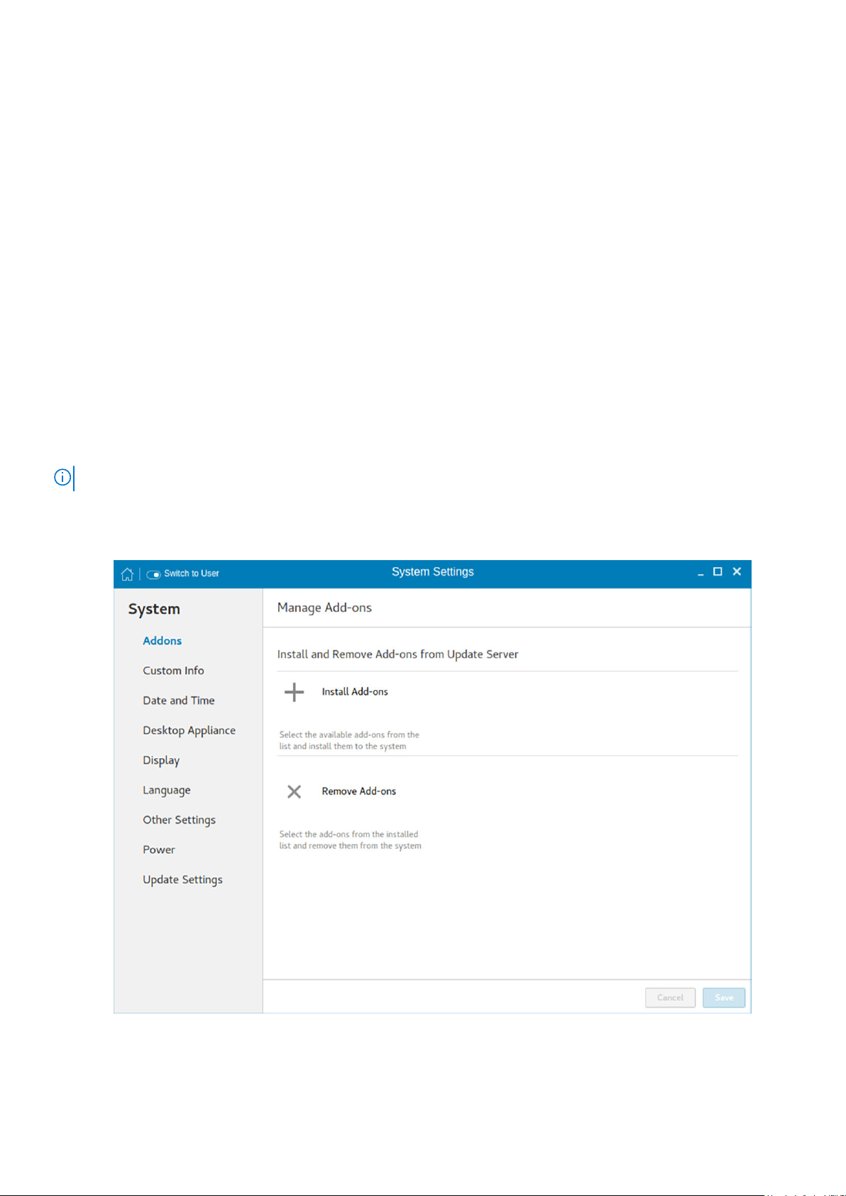
Configuring the addons
The Add-ons page enables you to install and remove Add-ons from INI server.
As a prerequisite, you must configure the location of add-ons on the Manager INI Configuration page. For more information
about INI management, see INI Management.
NOTE: The Addons screen is available only in Admin mode.
To install the add-on, od the following:
1. Click the + icon.
A list of available add-ons is displayed.
Figure 3. Install Add-ons
2. Select the required add-ons and install them to the system. You can select multiple add-ons at a time.
3. Click the to remove the Add-ons from the installed add-ons list.
Configuring thin client settings locally
13
Page 14
4. Click Save to save the changes.
NOTE: To remove an add-on, click the x icon, select the add-ons that you want to remove, and click Remove Add-ons.
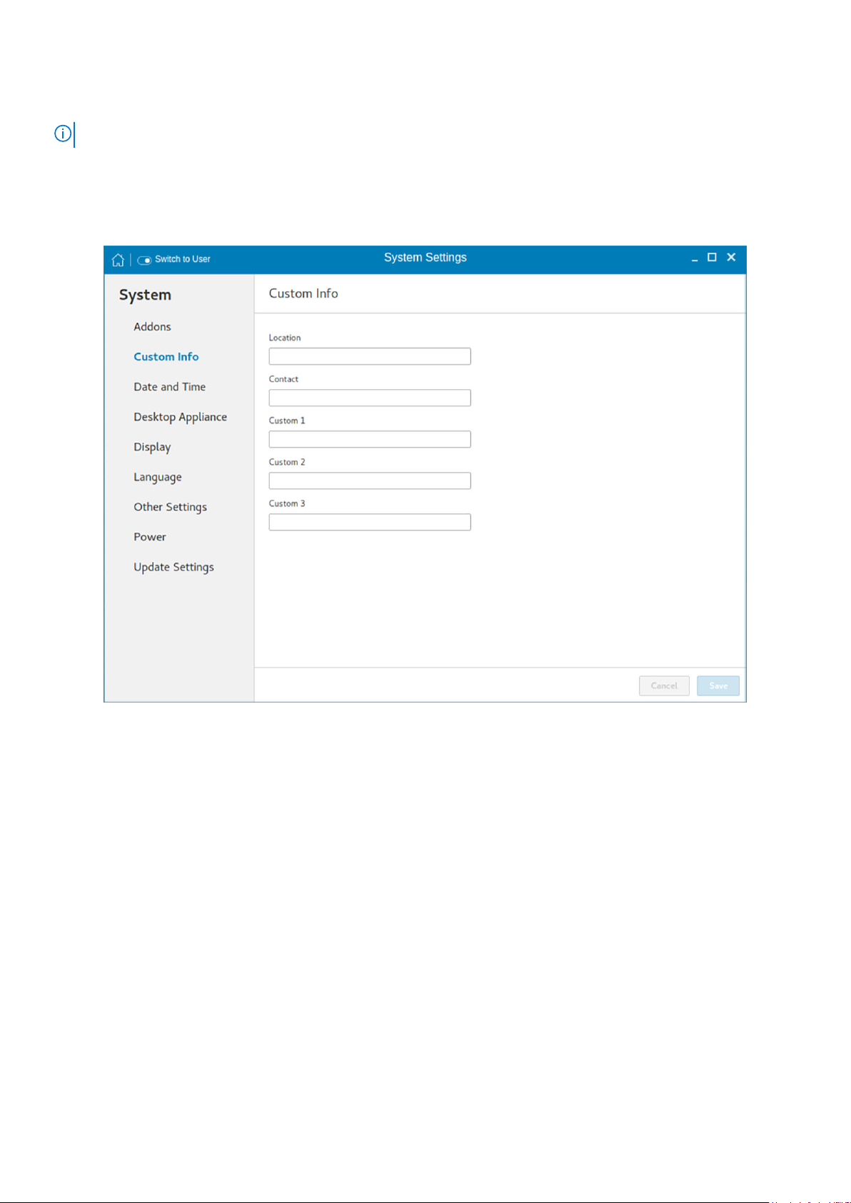
Setting the custom information
The Custom Info page enables you to set the device details.
Figure 4. Custom Information
To set the custom details for your thin client, do the following:
1. In the Location field, enter the device location.
2. In the Contact field, enter the contact details of the concerned authority.
3. In the Custom 1, Custom 2 and Custom 3 fields, enter the custom values pertaining to your device.
4. Click Save.
Setting the date and time
The date and time page enables you to set the date and time on your thin client.
To configure the date and time, do the following:
1. Click the Date and Time tab to set the date and time on your thin client.
The Date and Time screen enables you to set the device’s date, time, time zone, and whether or not the device should sync
its time with an NTP (Network Time Protocol) server. You can configure the Date and Time either manually or automatically.
The date, month and the year along with the time is displayed at the top of the screen.
The Time Format can be changed by using the Time Format drop-down list, and the Time Zone can be changed by using
the Time Zone drop-down list. The default time zone is America/Los_Angeles. Both changes can be performed regardless of
the ON or OFF state of the Set Time Automatically switch.
14
Configuring thin client settings locally
Page 15
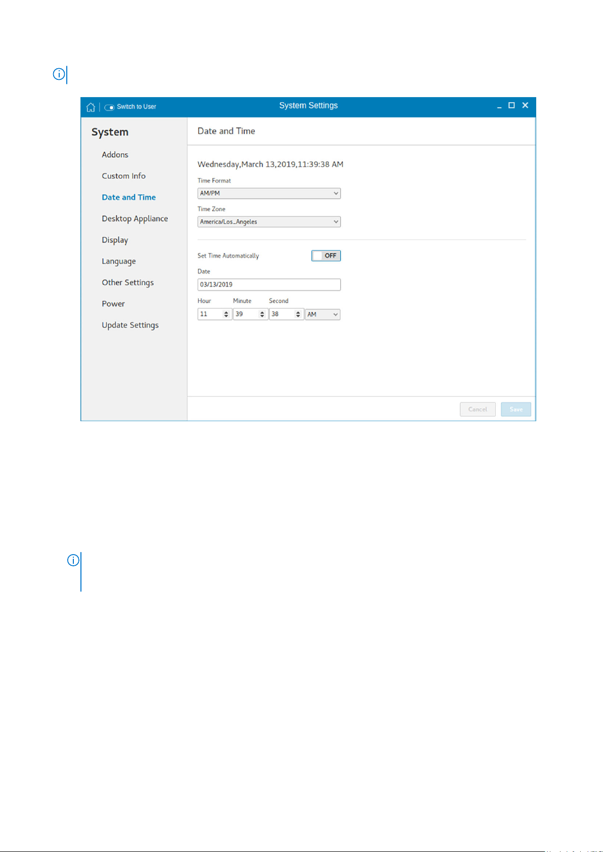
NOTE: By default, the Date and Time screen is available only in Admin mode
Figure 5. Date and time settings
2. To configure the Date and Time settings manually when the Set Time Automatically switch is in OFF position.
a. Click the date field and select the year, month and date.
Any changes performed in the date field such as, the time format is selected as 24 Hours or an additional AM/PM format,
is displayed at the top of screen.
The time field consists of Hour and Minute drop-down list.
b. Click Save to save the changes. Clicking Save when Set Time Automatically switch is in the OFF state also disables
NTP synchronization.
NOTE:
The Date and Time screen detects whether or not the NTP daemon is activated. By default, the NTP daemon
is deactivated. The manual setting time zone/date/time page is displayed, if the NTP daemon is deactivated.
Otherwise, the auto setting time zone page is displayed.
3. To configure the Date and Time automatically:
a. Click the Set Time Automatically button, to turn on the automatic settings. Note that internet access is required to use
this option. Turning on this option activates the NTP daemon and enables the NTP daemon to start syncing the device’s
time with the specified NTP server.
b. Click the + icon to add a new NTP server. The NTP Server IP or FQDN box is displayed on the page.
c. Enter the NTP Server IP or FQDN Server IP in the NTP Server IP or FQDN box. The + icon and x icons are displayed on
the right side of the box, when you start typing the characters in the box.
● Click the + icon to add the specified NTP server/FQDN to the NTP Server list. If a proper NTP server IP is not
entered, then a warning message is displayed on the page.
● Click the x icon to clear the IP address you have entered in the box.
d. The Delete, Up arrow and Down arrow icons are displayed next to the NTP Server name when you hover the mouse
over a particular NTP server in the NTP Server list.
● Click the Delete icon to delete the specified NTP server from the NTP Server list.
● Click Up arrow and Down arrow to change the order of the particular NTP server in the NTP Server list.
Configuring thin client settings locally
15
Page 16
NOTE:
● The Up arrow is enabled when the particular NTP server can be moved to the top in the NTP Server list and it is
disabled when the particular NTP server is listed at the top of the NTP Server list.
● Click Down arrow to change the order of the particular NTP by moving it down in the list.
● The Down arrow is enabled when the particular NTP server can be moved down in the NTP Server list and it is
disabled when the particular NTP server is listed at the bottom of the NTP Server list.
4. Click Save to save the changes. Clicking Save button when, Set Time Automatically is in ON position, enables NTP
synchronization.
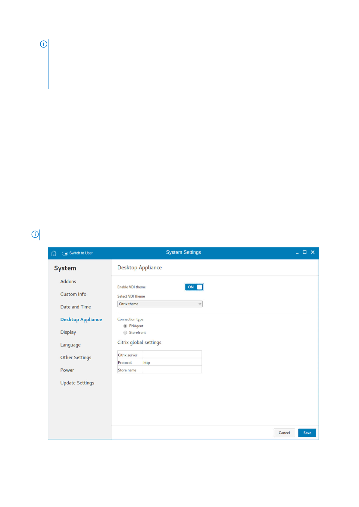
Configuring desktop appliance
We can configure Desktop Appliance (Power On to Power Off VDI theme) using GUI, INI and DHCP. For INI configuration, refer
the tags description of DesktopAppliance, CitrixConnectionType, PNAgentServer and Storename INI parameters.
For DHCP configuration,
● 181—Configure Citrix server url—either specify pnagent url xyz.com/citrix/pnagent/config.xml, storefront xyz.com/citrix/
store/discovery, or IP/FQDN.
● 203—Type of VDI theme
● 204—Type of Citrix server
● 205—Storename. For more information, see DHCP option tags
By default, the Desktop Appliance screen is available only in Admin mode. Any changes made through Desktop Appliance
screen is saved and continued for the built-in thinuser.
1. Click the ON/OFF button to enable or disable the VDI theme option after you log in to the session.
2. From the drop-down list, select your preferred VDI theme.
NOTE: Only Citrix theme is supported in this release.
Figure 6. Desktop appliance settings
16
Configuring thin client settings locally
Page 17

3. Select the type of Citrix Server.
Citrix server, Protocol and Storename can be configured from the Change global settings page. Go to All connections
page, select the Citrix option and then select the Change global settings option to configure the Citrix settings. For more
settings for Applications or Desktops, go to All connections page, select Citrix option and then select Change global settings
option to configure the Applications or Desktops settings.
4. Click Save.
You are prompted to restart the system.
5. Click OK to save the changes and restart the system in selected theme.
6. After the system is restarted, a log on button is displayed.
a. Click the Log On button.
Figure 7. Login screen
You are required to authenticate by entering the following credentials:
● User name
● Password
● Domain
You are logged on to the Citrix receiver.
Configuring thin client settings locally
17
Page 18
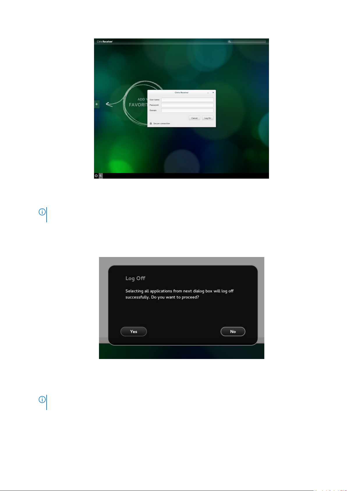
Figure 8. Authentication screen
If the logon authentication fails, you are prompted with a screen. Click try again to query the server again.
NOTE:
You can break kiosk mode and enter into admin mode at any point of time by using the shortcut key. The
shortcut key is Ctrl + Alt + Shift + F11.
b. After the successful login, you can add the required applications or desktops from the left + button.
c. Click the application or desktop to start it. You are prompted with an error if there as an error message.
d. You can logout at any point of time by clicking the power icon on task bar. Depending on whether any application is
opened, you are prompted with an error message.
Figure 9. Log Off screen
e. If any applications are running, connection center window is displayed, select each application and either log off or
disconnect. Following which click the cross to close the control center and logoff completely.
If you do not follow above procedure to log off, you may see sessions active and running behind the displayed
NOTE:
log on button.
18 Configuring thin client settings locally
Page 19
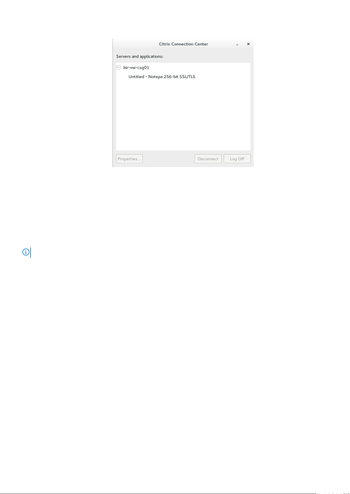
Figure 10. Citrix connection center
Customizing the display
By default, the Customize your display screen is available in both user mode and admin mode. Any changes to display
preferences are saved and available for the built-in user named thinuser. In a Dual-display configuration, if both displays are
connected, then by default, the displays are in the extended mode. The primary display is on the left (display 1), and the
secondary display is on the right (display 2). The resolutions of the displays are automatically detected by the system by
analyzing the display capabilities built in.
NOTE: Before changing the resolution of the screen, click the Display icon.
To customize the display, do the following:
1. Click the Display tab.
The Customize Your Display page is displayed.
Configuring thin client settings locally
19
Page 20
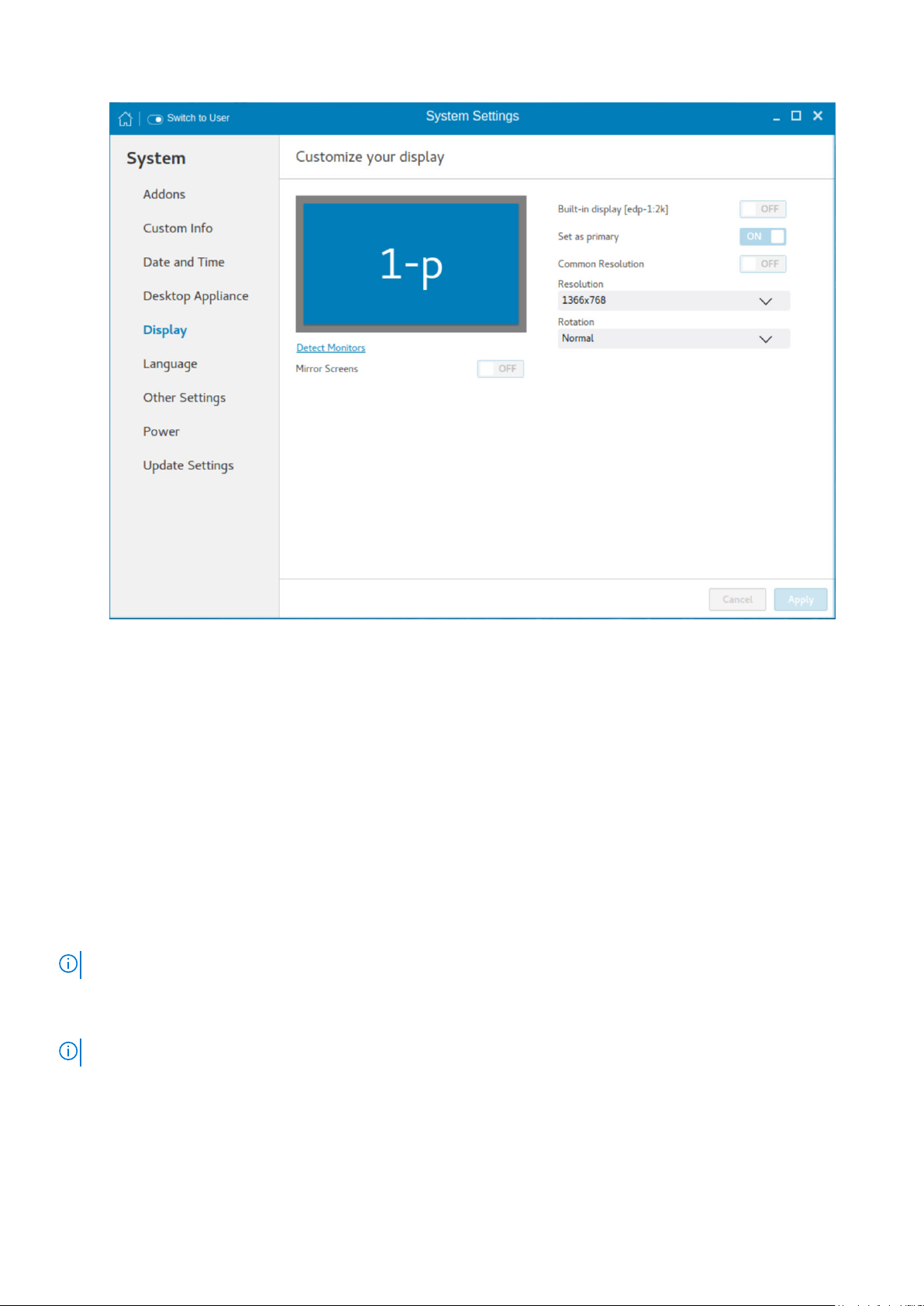
Figure 11. Display settings
2. To set a common resolution for all the connected displays, click the ON/OFF button.
3. From the Resolution drop-down list, select the preferred resolution.
4. From the Rotation drop-down list, select the rotation.
● Normal
● Right
● Left
● Upside-down
5. To enable the screen mirroring for secondary displays in a multi display configuration, click the ON/OFF button.
6. To enable the Set as primary option, click the ON/OFF button. This option enables you to set the selected display as
primary.
Customizing multiple displays on the Wyse 5070 extended thin client
NOTE: This section is applicable only to the Wyse 5070 extended thin client.
By default, the Customize your display screen is available in both user mode and admin mode. Any changes to display
preferences are saved and available for the built-in user named thinuser. For information about hardware capability and ports
preferences, see Dell Wyse ThinLinux 2.2 Operating System and Add-ons Release Notes at www.dell.com/support.
NOTE: INI parameters are not supported on a multi-display setup with more than three displays.
To customize the display, do the following:
1. Click the Display tab.
The Customize Your Display page is displayed.
2. Select a display that you want to turn on or turn off from the display grid, and click the ON/OFF button.
20
Configuring thin client settings locally
Page 21
NOTE: To turn off a display, select a display from the display grid, and click the Display OFF button. Ensure that you
arrange all the active displays first and move all the inactive displays to the end of the layout.
3. To enable the Set as primary option, click the ON/OFF button. This option enables you to set the selected display as the
primary display.
4. To set a common resolution for all the connected displays, click the ON/OFF button.
5. From the Resolution drop-down list, select the preferred resolution.
6. From the Layout drop-down list, select any of the following layout types:
NOTE: After you install the ThinLinux image, select the 2 screens per column layout and arrange all displays with 4K
resolution followed by displays with 2K resolution. If any of the display enters the mirror mode or overlaps after reboot
or factory reset, you must follow the preceding configuration.
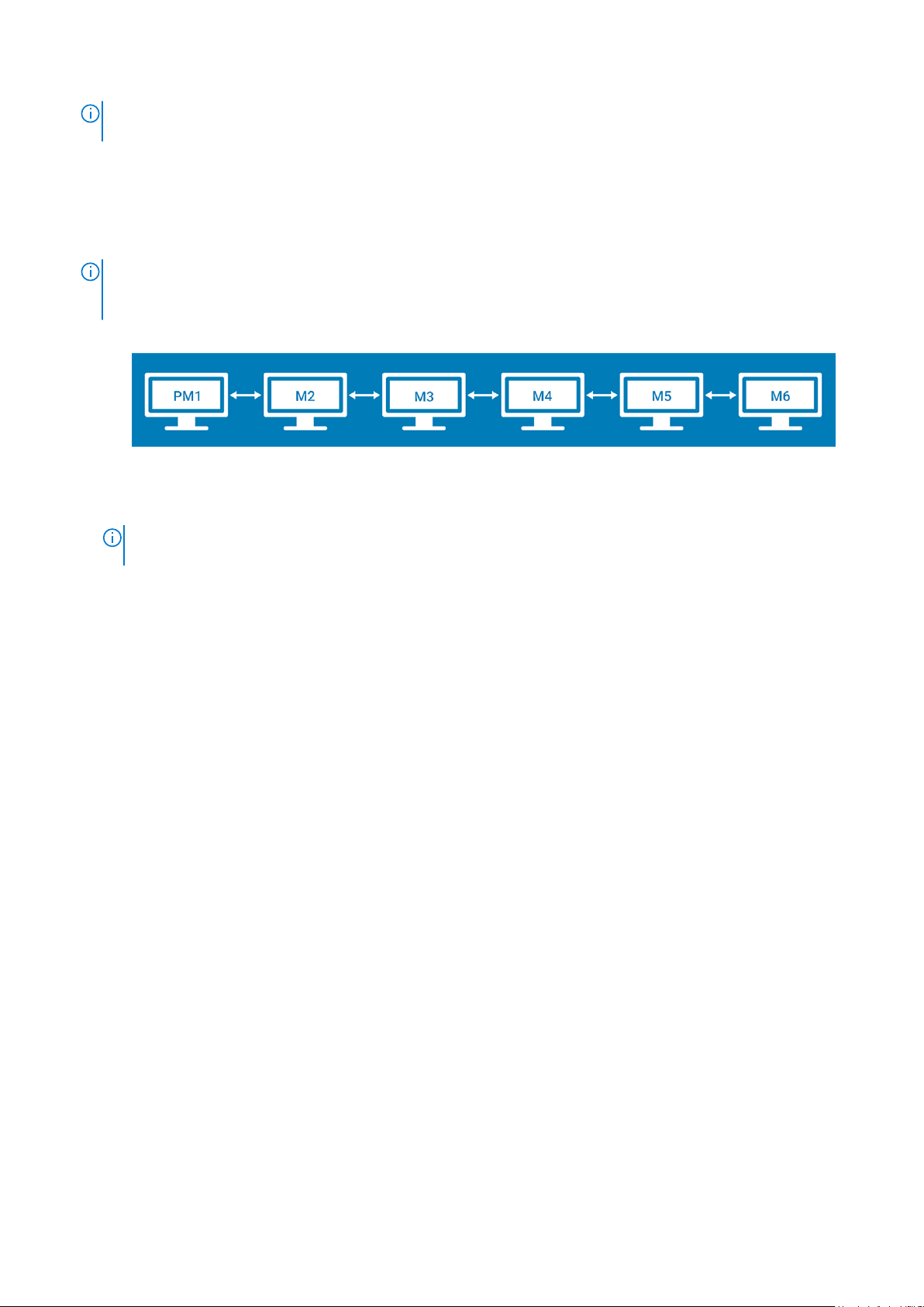
● Horizontal—Enables you to drag the applet window horizontally, from the primary display to the rest of the displays.
Figure 12. Horizontal layout
PM1—Primary display (display 1), M2—Display 2, M3—Display 3, M4—Display 4, M5—Display 5, M6—Display 6
NOTE:
The horizontal option is available for either six displays with 2K resolution or four displays with 4K resolution.
This option is not applicable for six displays with four 4K and two 2K resolutions.
● Vertical—Enables you to drag the applet window vertically, from the primary display to the rest of the displays.
Configuring thin client settings locally
21
Page 22
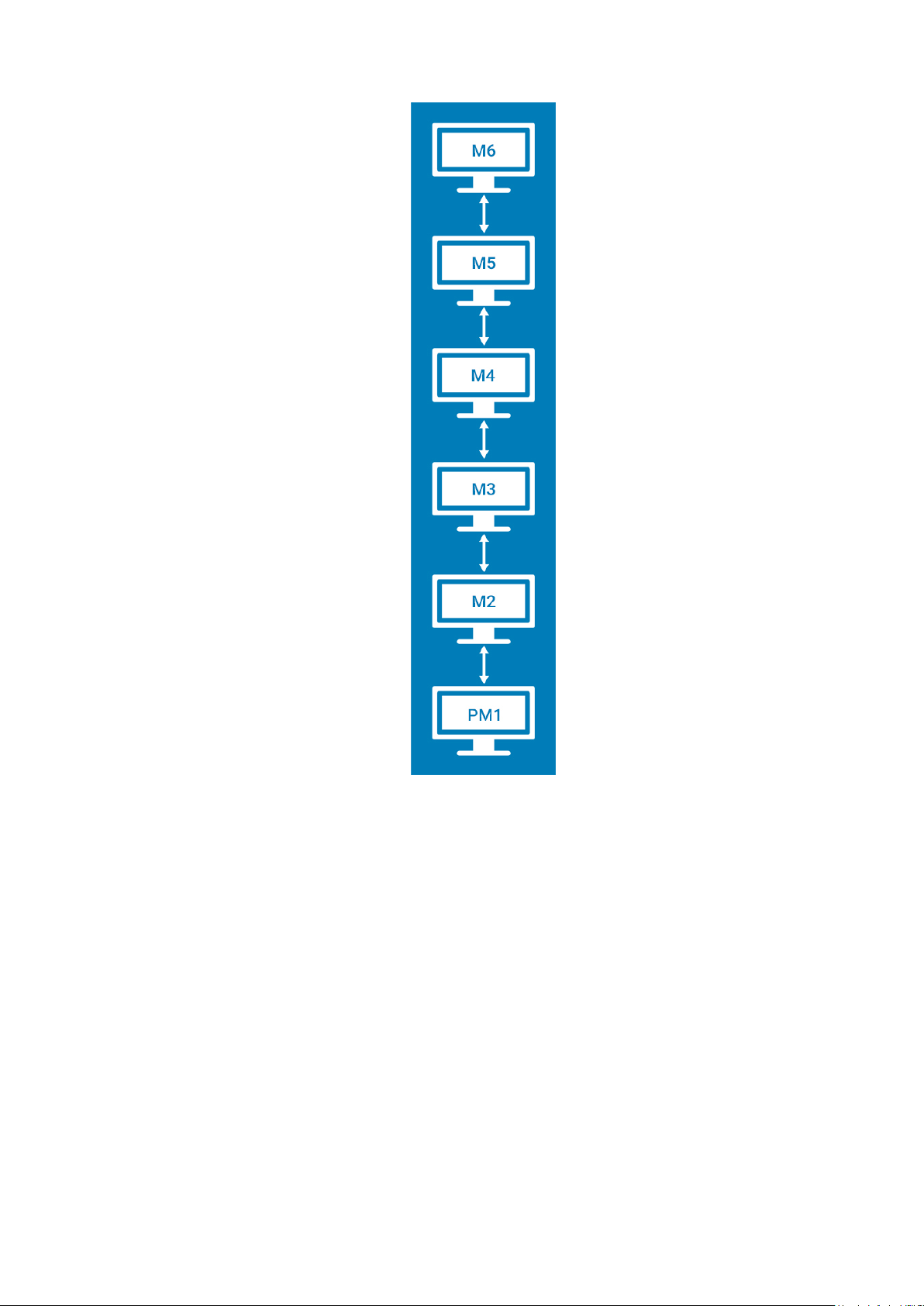
Figure 13. Vertical layout
● 3 screens per column—Enables you to drag the applet window from the primary display to the rest of the displays as
described in the following table. For example, you can drag the applet window from PM1 to M2 horizontally, or to M3
vertically.
22
Configuring thin client settings locally
Page 23
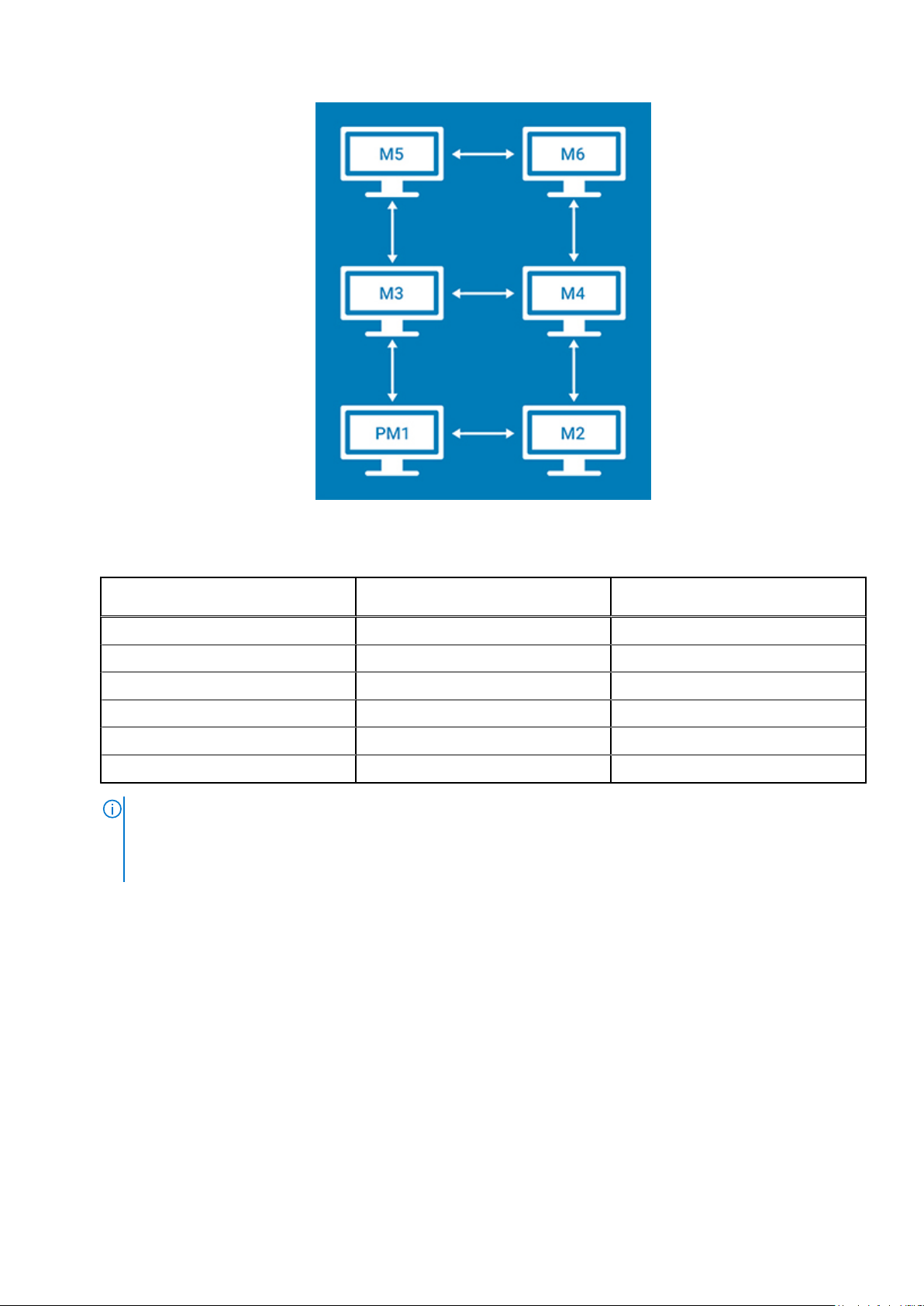
Figure 14. 3 Screens Per Column Layout
Table 2. 3 screens per column
Applet window placement at
display
Primary display (display 1) Display 2 Display 3
Display 2 Primary display (display 1) Display 4
Display 3 Display 4 Display 5, Primary display (display 1)
Display 4 Display 3 Display 2, Display 6
Display 5 Display 6 Display 3
Display 6 Display 5 Display 4
NOTE:
○ You cannot drag the applet window diagonally across displays.
○ Dell recommends that you set up even number of displays for a better user experience. 3-display and 5-display
setups are not recommended.
● 2 screens per column—Enables you to drag the applet window from the primary display to the rest of the displays as
described in the following table. For example, you can drag the applet window from PM1 to M2 horizontally, or to M4
vertically.
Traverse horizontally to display Traverse vertically to display
Configuring thin client settings locally
23
Page 24
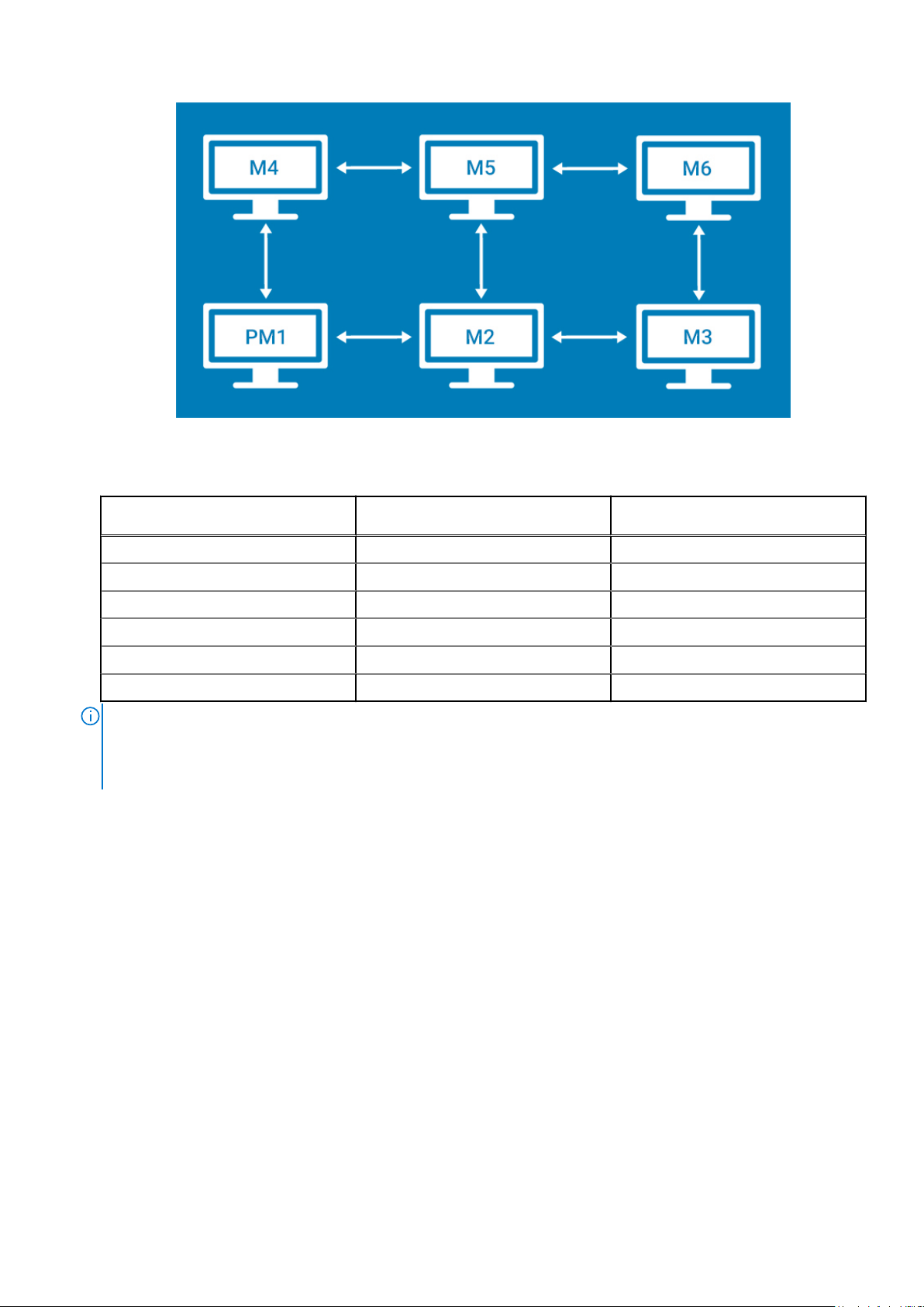
Figure 15. 2 screens per column
Table 3. 2 screens per column
Applet window placement at
display
Primary display (display 1) Display 2 Display 4
Display 2 Display 3, Primary display (display 1) Display 5
Display 3 Display 2 Display 6
Display 4 Display 5 Primary display (display 1)
Display 5 Display 4, Display 6 Display 2
Display 6 Display 5 Display 3
NOTE:
● You cannot drag the applet window diagonally across displays.
● Dell recommends that you set up six displays for a better user experience. 4-display and 5-display setups are not
recommended.
Traverse horizontally to display Traverse vertically to display
Selecting the language
By default, the Language applet is available only in Admin mode. Any changes made through Language applet is saved and
continued for the built-in thinuser.
From the Select Language drop-down list, select the language of the screen from the list of supported languages and click
Save to save your settings.
24
Configuring thin client settings locally
Page 25
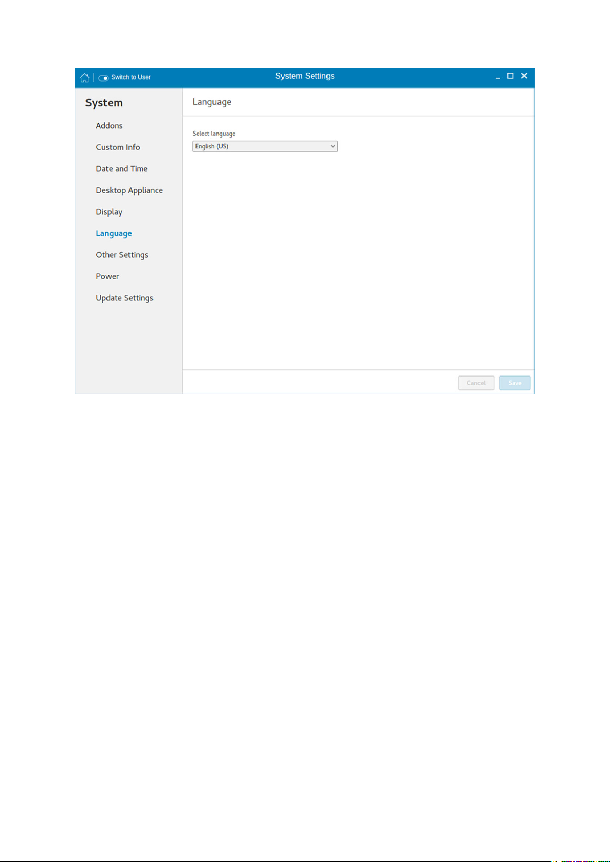
Figure 16. Language settings
Other settings
The Other Settings page enables you to enter the hostname of the thin client to add or delete the additional entries to
the /ect/hosts file in the device. Any changes that are made through Other Settings screen are saved and preserved over
reboots for the built-in thinuser. The Other Settings screen is available only in admin mode.
Configuring thin client settings locally
25
Page 26
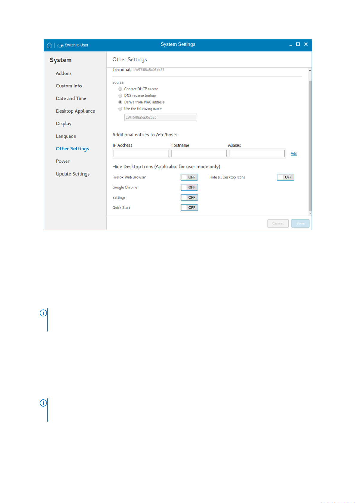
Figure 17. Other settings
To configure the other settings, do the following:
1. In the Source section, configure one of the following options:
● Contact DHCP server—If you set the hostname of the thin client by selecting the DHCP server option, the hostname is
set to the standard host-name tag received from the DHCP server. If the DHCP server does not provide the host-
name tag, the device retains the previously set hostname.
● DNS reverse lookup—If you select DNS reverse lookup option to enter the hostname of the thin client, a reverse
DNS lookup operation is performed using the existing IPv4 address of the thin client, and the hostname is set to the
received value.
NOTE:
The previous hostname is retained if the device cannot perform a successful reverse DNS lookup operation
due to reasons such as, network connection is not established, DNS servers are not established or are invalid, and
the IP address is not in the DNS server’s list.
● Derive from MAC address—Select the Derive from MAC address option to specify the host name of the thin client.
You can specify the hostname by using the MAC address. The Ethernet of the thin client interfaces with the MAC
address. It creates the hostname by extracting the MAC address from its field separators, such as, (:) and the MAC
address is prefixed with the string LWT. For example, a device with MAC address of 00:80:64:c1:8b:14 has MAC
derived hostname as LWT008064c18b14. If you want to use the manually named device as a seed device for Merlin image
pulling, you must be cautious in specifying the hostname manually. The changed hostname is pushed to other devices and
these devices use the same hostname. Only through device factory reset, you can recover the default value by using
MAC address.
● Use the following name—This option enables you to enter your preferred hostname. When you log in to the session,
the screen displays the previous hostname in the box and in the Terminal option.
The hostname entered is not authenticated if the string entered has a white space. The first part of the
NOTE:
string up to the first white space is used to set the hostname of the devices. All white spaces at the beginning of the
string are ignored, and the maximum hostname string size is 64.
2. In the Additional entries to /etc/hosts section, you can set the device name and update the entries on the /etc/hosts
file. This option enables you to add to the preset default data, and update or delete the existing entries. To configure this
option, do the following:
a. Enter the IP address, host name,and Aliases in the respective fields.
26
Configuring thin client settings locally
Page 27
b. Click the Add option, and update the default data.
3. In the Hide Desktop icons section, configure any of the following options:
NOTE: These options are applicable for user mode only.
● Firefox Web Browser—Click the ON/OFF button to enable or disable this option. If you enable this option, the Mozilla
Firefox web browser icon is not displayed on the desktop.
● Google Chrome—Click the ON/OFF button to enable or disable this option. If you enable this option, the Google
Chrome web browser icon is not displayed on the desktop.
● Settings—Click the ON/OFF button to enable or disable this option. If you enable this option, the Settings app icon is
not displayed on the desktop.
If the Settings app is hidden, and if you log into the thin client with user credentials, then you cannot open the Settings
app or switch to the admin mode. You can restore the Settings app using one of the following methods:
○ Use INI parameters.
○ Log in to the thin client with admin credentials and enable the Settings option.
○ Perform a factory reset or factory recovery.
● Quick Start—Click the ON/OFF button to enable or disable this option. If you enable this option, the Quick Start
application is not displayed on the desktop.
● Hide all Desktop icons—Click the ON/OFF button to enable or disable this option. If you enable this option, the
created connection icons are not displayed on the desktop.
4. Click Save.
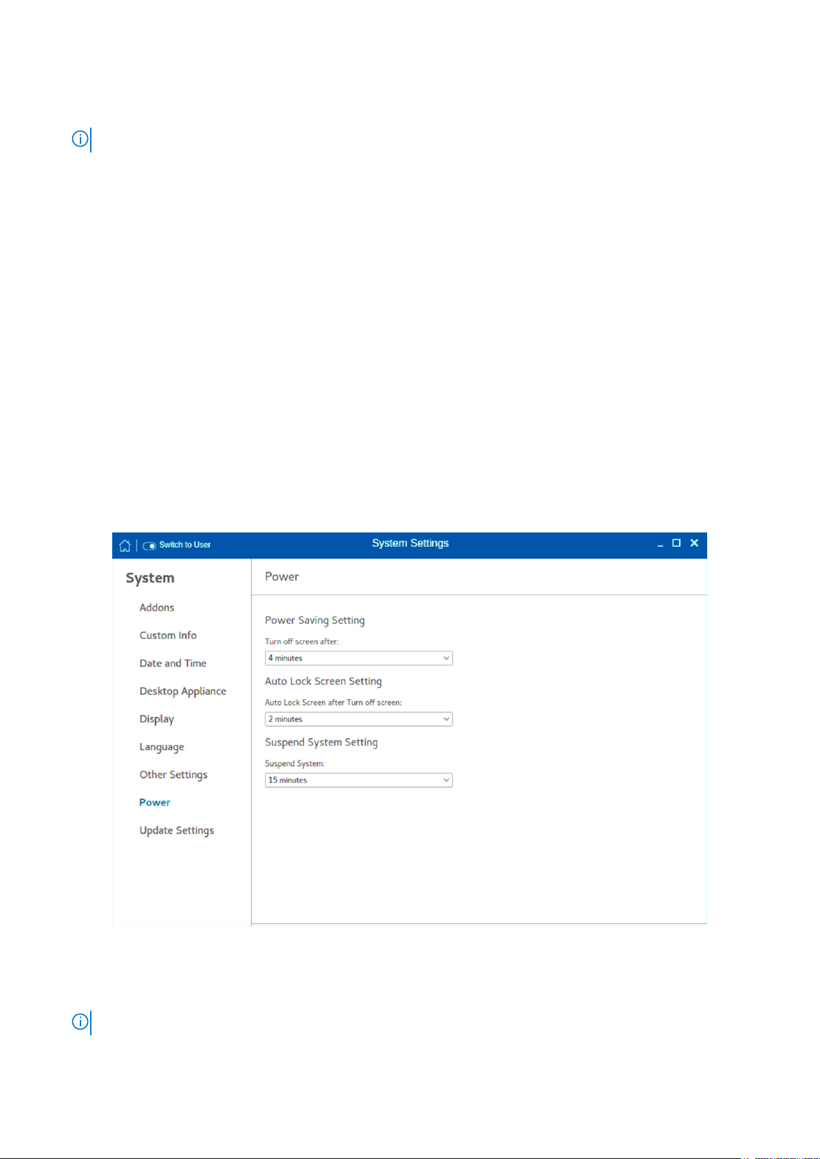
Configuring the power-saving settings
The Power page enables you to configure the power-saving settings.
Figure 18. Power Saving settings
To configure the power-saving settings, do the following:
1. From the Turn off screen after drop-down menu, select the time to turn off the display after the specified idle time.
NOTE: By default, the idle time is set to 4 minutes to comply with ENERGY STAR category.
Configuring thin client settings locally 27
Page 28

2. From the Auto Lock Screen after Turn off screen drop-down menu, select the time to lock the thin client automatically
after the display is turned off.
3. From the Suspend System Setting drop-down menu, select the time in seconds to suspend the thin client after the
specified idle time. This option enables your device to enter the S3 power state (low-power), and quickly resume your work
without rebooting the device.
NOTE: By default, the idle time is set to 15 minutes.
If you are using a Wyse 5470 Thin Client, you can configure the advanced settings. To configure these settings, clickAdvanced
Settings, and do the following:
NOTE: The battery status bar displays the amount of charge remaining on the system. This is applicable only on Wyse 5470
Thin Client.
1. To adjust your screen brightness, move the Screen resolution slider.
2. To increase your keyboard brightness, move the Keyboard Brightness slider.
3. Click the ON/OFF button to enable or disable the Dim screen when inactive option. When you enable this option, the
brightness of your screen is reduced when your system is idle.
4. From the Blank screen drop-down list, select the idle time after which the blank screen is to be displayed and system is
locked.
5. Click the ON/OFF button to enable or disable the Wifi option.
NOTE: It is recommended to turn off the Wi-Fi option to save power.
6. Click the ON/OFF to enable or disable the mobile broadband option.
7. Click the Suspend and power off button to configure the time to wait after a period of inactivity (i.e., no keyboard or
mouse action) before the thin client shuts down manually or automatically. Click the Automatic suspend button and choose
the following:
a. From the On battery power drop-down menu, select the time in minutes to set the screen to turn off and lock the thin
client after the specified idle time when not plugged in to battery.
b. From the Plugged in drop-down menu, select the time in minutes to set the display to turn off and lock the thin client
after the specified idle time.
Update settings
By default, the delayed update option is enabled. You should provide the File Server credentials using INI parameters to start the
Merlin image upgrade process. For more information, see the latest Dell Wyse ThinLinux INI Reference Guide on www.dell.com/
support.
28
Configuring thin client settings locally
Page 29
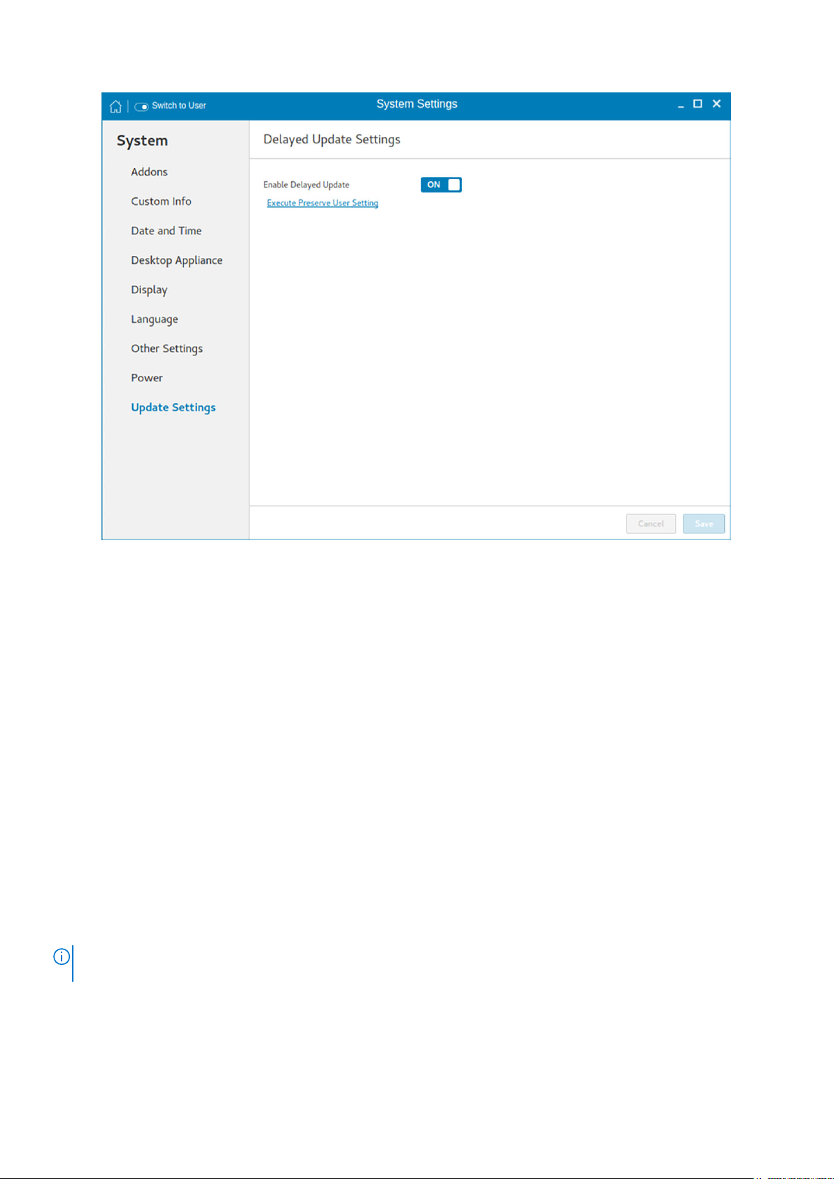
Figure 19. Delayed update settings
Execute Preserve User Setting—Use this option to retain the previous settings after you upgrade the ThinLinux build to the
latest version. To enable the preserve user settings, click the link. This option is supported only when imaging is performed using
the USB Imaging tool.
Peripherals
On the System Settings page, click the Peripherals icon. The following tabs are displayed on the left pane of the System
Settings page.
● Bluetooth
● Keyboard
● Mouse and Touch pad
● Printers
● Sound
● USB Manager
Configuring the Bluetooth settings
The Bluetooth page enables you to configure the Bluetooth function, and connect Bluetooth devices to your thin client. You
can use Bluetooth to transfer files between devices.
The Bluetooth option can be configured only in admin mode. When you attempt to enable the Bluetooth function in
NOTE:
user mode, a warning message is displayed.
Prerequisite—Ensure that the Bluetooth device that you want to connect to is discoverable and placed within the range of
your thin client.
To configure Bluetooth, do the following:
1. On the Bluetooth page, click the ON/OFF button to enable or disable the Bluetooth function.
Configuring thin client settings locally
29
Page 30
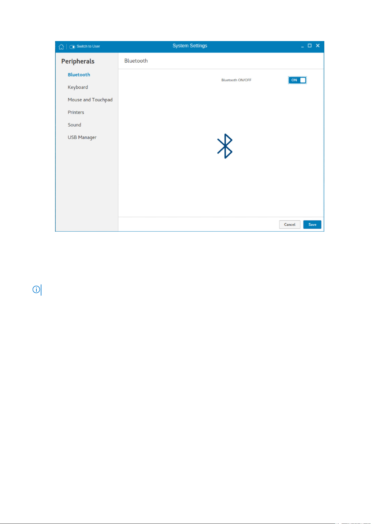
Figure 20. Bluetooth settings
2. After the Bluetooth is enabled, click Save.
On the upper-right corner of the screen, the Bluetooth Enabled notification is displayed for a few seconds.
3. Click the Bluetooth icon to start searching for Bluetooth devices.
The thin client searches and lists the Bluetooth devices that are discoverable.
NOTE: If the Bluetooth ON/OFF button is disabled, the device does not support the Bluetooth functionality.
4. Click the Bluetooth device from the list.
5. When prompted, confirm the Bluetooth PIN on your external Bluetooth device, and then click Confirm on your thin client.
If the pairing is successful, a Connected status is displayed next to the device name.
6. Close the Bluetooth page.
Send files to a Bluetooth device
You can use Bluetooth to send files from your thin client to an external device.
Prerequisite—Ensure that you have turned on Bluetooth, and the devices are paired.
1. In the Devices list, click the desired device.
A dialog box specific to your connected device is displayed.
2. Click Send Files.
3. Choose the file you want to send and click Select.
4. On the paired device, accept the file.
A progress bar is displayed in the Bluetooth File Transfer dialog box.
5. When the file transfer is complete, Click Close.
If the file transfer is unsuccessful, click Retry.
Setting the keyboard preferences
The Keyboard setting page enables you to set the Keyboard preferences and make the Keyboard layout.
30
Configuring thin client settings locally
Page 31

NOTE: By default, the Keyboard screen is available in both User mode and Admin mode. Any changes made through
Keyboard preferences screen is saved and preserved over reboots for the built-in thinuser
Figure 21. Keyboard preferences
1. Click the ON/OFF button to disable or enable the Key presses repeat when held down option after you log in to the
session.
2. Move the slider to the left to decrease the repeated delay time of the pointer or move the slider to the right to increase the
repeated delay time of the pointer.
3. Move the slider to the left to decrease the repeat rate of the pointer or move the slider to the right to increase the repeat
rate of the pointer.
4. In the keyboard layout box, select the layout you want to use and click Add to include the preferred layout in the currently
added layouts list.
5. Select the preferred keyboard layout from the currently added layouts list, and click Set as Default Layout button to set
the default layout.
NOTE: The default keyboard layout is listed on the top of the currently added layout list.
6. Click Save to save your changes.
Wyse 5470 thin client supports the following short-cut key functions:
● Fn+F1—Mutes Audio
● Fn+F2—Decreases volume
● Fn+F3—Increases volume
● Fn+F10—Adjusts keyboard backlight brightness and toggles backlight on/off
● Fn+F11—Decreases LCD brightness
● Fn+F12—Increases LCD brightness
Setting the mouse and touchpad preferences
By default, the Mouse and Touchpad screen is available in both User mode and Admin mode. Any changes made through the
Mouse and Touchpad preferences screen is saved and preserved over reboots for the built-in thinuser.
Configuring thin client settings locally
31
Page 32

Figure 22. Mouse and touch pad settings
The Mouse and Touchpad settings page enables you to set the mouse and touch pad preferences.
1. Click Right or Left to set the primary button of the mouse or touchpad.
2. Move the slider to the left to increase the speed of the pointer when double-clicked or move the slider to the right to
decrease the length of double-clicked.
3. Move the slider to the left to increase the speed of the mouse pointer or move the slider to the right to decrease the speed
of the mouse pointer.
4. Click Save to save your changes.
Configuring the printer settings
By default, the Printers screen is available only in Admin mode.
32
Configuring thin client settings locally
Page 33

Figure 23. Printers - localhost
1. Click the printer icon.
The Printers - localhost dialog box is displayed.
2. Click the Add button to include a new printer.
The New Printer window is displayed. You can configure the printer type based on your preference.
NOTE:
If a USB printer is connected, then it is displayed by default. The printer is not found if wrong address is
provided or the USB is not attached.
3. Select a device type from the following options:
● LPT Port—Select this option if your printer is attached to the thin client through an LPT port, and enter valid values.
● Serial Port—Select this option if your printer is attached to the thin client through a serial port, and enter valid values.
● Enter URL—Select this option to enter URL for a local printer, and enter valid values.
● Network Printer—Select this option if you are using a network printer. Use any one of the options for configure your
network printer:
○ Windows Printer via SAMBA
○ Internet Printing Protocol (ipps)
○ LPD/LPR Host or Printer
○ Internet Printing Protocol (https)
○ Internet Printing Protocol (ipp14)
○ Internet Printing Protocol (ipp)
○ AppSocket/HP Jet Direct
Enter valid values to search for your printer host on network.
4. After you configure the printer based on your preference, click Forward.
The thin client searches for the available printer drivers.
5. Select a printer driver, and click Forward. You can select the printer driver from database or search for a printer driver to
download. You can also browse to the location where you have saved the PostScript Printer Description (PPD) files, and
select the appropriate file.
6. Specify the Printer Name, Description, and Location.
7. Click Apply.
The printer is listed on the screen.
Configuring thin client settings locally
33
Page 34

NOTE: You can click Print Test Page to test the printer.
8. Right-click the printer icon, and click Properties.
9. Configure the following tabs based on your printing preference:
● Settings—Use this tab to configure the location, device URL, model, and printer state.
● Policies—Use this tab to configure the printer state, error policy, operation policy, starting banner, and ending banner.
● Access Control—Use this tab to set the printing privileges to users.
● Printer Options—Use this tab to configure the general printer settings, such as media size.
● Job Options—Use this tab to specify the default job options for the printer.
● Ink/Toner Levels—Use this tab to view the marker levels and status messages of the printer.
10. Click OK.
The thin client is ready to print.
Configuring the sound settings
By default, the sound screen is available in both user mode and admin mode. Any changes to the sound settings are saved and
available for the built-in user named thinuser.
To configure the sound settings, do the following:
Figure 24. Sound
1. Click the Sound icon.
2. Move the Output volume slider to adjust the output or speaker volume. Click the ON/OFF button to enable or disable the
output volume.
3. Click the Output tab, and do the following:
34
Configuring thin client settings locally
Page 35

Figure 25. Sound output
a. From the output devices list, select a device for sound output. The default audio output is the Analog Output.
b. Based on the channels available for the selected output device and profile, move the Balance slider to adjust the sound
balance.
c. From the drop-down list, select an audio profile.
d. Click Test Speakers. A dialog box is displayed. You can test the speaker by playing sample wave files.
4. Click the Input tab, and do the following:
Figure 26. Sound input
Configuring thin client settings locally
35
Page 36

a. From the input devices list, select a device for sound input. The default audio input is the Analog Input.
b. Move the Input Volume slider to adjust the input or Mic volume. Click the ON/OFF button to enable or disable the input
volume.
The Input level bar displays the input volume peak level.
5. Click the Sound Effects tab, and do the following:
Figure 27. Sound effects
a. From the alert sound list, select an alert sound theme.
b. Move the Alert Volume slider to adjust the volume level of alert sounds. Click the ON/OFF button to enable or disable
the alert volume.
6. Click the Applications tab to view all the applications that are currently playing a sound file, or recording audio.
36
Configuring thin client settings locally
Page 37

Figure 28. Applications
Managing the USB ports and devices
The USB Manager page enables you to configure and manage the USB ports and devices that are connected to your thin
client. To configure the USB port and device settings, do the following:
1. In the USB Ports tab, configure any of the following options:
Configuring thin client settings locally
37
Page 38

Figure 29. USB Manager
● Enable USB Boot Support—Click the ON/OFF button to enable or disable the USB boot setup. If this option is
enabled, you can use a USB storage device to boot the operating system.
● Enable Exernal USB Ports—Click the ON/OFF button to enable or disable the external USB ports. If the USB port is
disabled, the operating system cannot detect the device that is attached to this port.
● BIOS Password—Enter the BIOS password.
NOTE:
If BIOS is configured to use the admin password and if the BIOS password is not set, any changes to the
USB port settings are not saved after rebooting the thin client.
2. In the USB Devices tab, configure any of the following options:
● Enable all USB Devices—Click the ON/OFF button to enable or disable this option. If this option is enabled, the
operating system detects all USB devices that are connected to the thin client.
If this option is disabled, you must enable one of the following options:
○ Disable all USB Devices
○ Disable all USB Devices excluding HID
○ Disable by USB Class
● Disable all USB Devices—Click the ON/OFF button to enable or disable this option. If this option is enabled, the
operating system does not detect USB devices that are connected to the thin client. If this option is disabled, you must
enable one of the following options:
○ Enable all USB Devices
○ Disable all USB Devices excluding HID
○ Disable by USB Class
NOTE:
If the Disable all USB Devices option is enabled, all USB devices including keyboard and mouse are disabled. You
cannot reset the settings or use the G-key option.
● Disable all USB Devices excluding HID—Click the ON/OFF button to enable or disable this option. If this option is
enabled, the operating system detects only Human Interface Devices (HID) such as keyboard and mouse.
If this option is disabled, you must enable one of the following options:
○ Enable all USB Devices
38
Configuring thin client settings locally
Page 39

○ Disable all USB Devices
○ Disable by USB Class
● Disable by USB Class—Click the ON/OFF button to enable or disable this option.
If this option is enabled, you must configure any of the following options:
○ Disable Video Devices—Click the ON/OFF button to enable or disable this option. If this option is enabled, the
operating system does not detect the video devices that are connected to the thin client.
○ Disable Storage Devices—Click the ON/OFF button to enable or disable this option. If this option is enabled, the
operating system does not detect the storage devices that are connected to the thin client.
○ Disable Smartcard Devices—Click the ON/OFF button to enable or disable this option. If this option is enabled, the
operating system does not detect the smart card devices that are connected to the thin client.
○ Disable Audio Devices—Click the ON/OFF button to enable or disable this option. If this option is enabled, the
operating system does not detect the audio devices that are connected to the thin client.
○ Disable Printer Devices—Click the ON/OFF button to enable or disable this option. If this option is enabled, the
operating system does not detect the printers that are connected to the thin client.
3. Click Save to save the settings.
Network
On the System Settings page, click the Network tab to view the Network Settings page.
1. Click the Network icon.
2. The Network settings page is displayed. In the left-pane, the following tabs are available for you to configure.
● Wi-Fi
● Wired
● Network proxy
Configuring the wi-fi settings
To configure the Wi-Fi settings, perform the following steps:
1. In the left-pane, click Wi-Fi tab.
2. Click the ON/OFF button to enable or disable the Wi-Fi option. The list of wireless SSID is displayed if broadcast is enabled.
Configuring thin client settings locally
39
Page 40
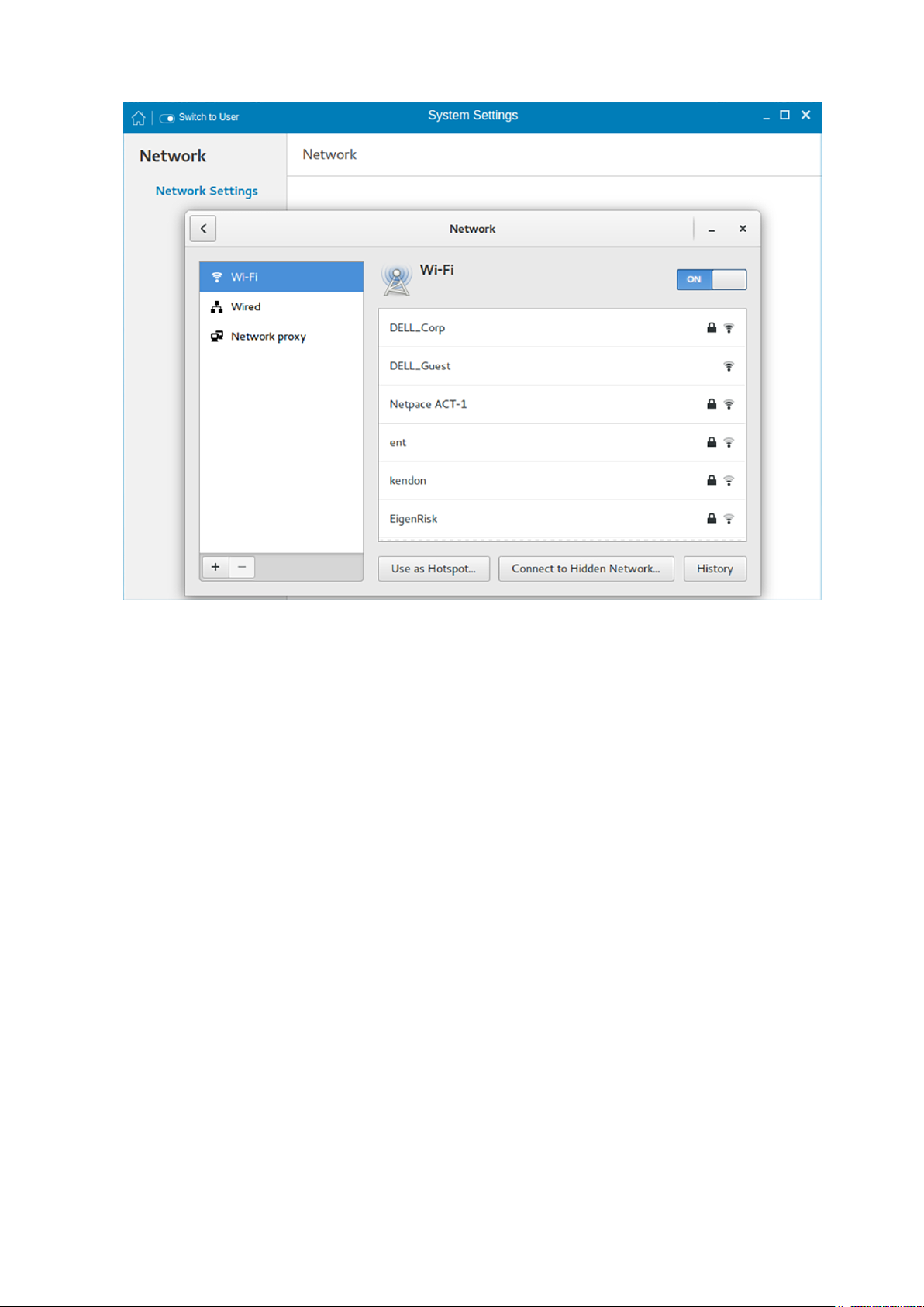
Figure 30. Wi-Fi Settings
3. To connect to Wi-Fi connection, select the preferred wireless SSID from the list displayed.
4. Click the Connect to Hidden Wi-Fi Network button. The Connect to Hidden Wi-Fi Network window is displayed.
40
Configuring thin client settings locally
Page 41

Figure 31. Hidden Wi-Fi Network
5. Enter the name and security details of the hidden network that you want to connect to.
Table 4. Hidden network
Parameter Description
Network name Enter the preferred network name.
Wi-Fi security From the drop-down list, select the security type.
6. On the Network page, click the History button to view the previous Wi-Fi connections and details.
Configuring wired network connection settings
To configure the wired connection settings, perform the following steps:
1. Click the Wired tab. The following attributes are displayed if the network cable is connected to your thin client and wired
connection is established.
● IPv4 Address
● IPv6 Address
● Hardware Address
● Default Route
● DNS
NOTE: After the network is disconnected, only hardware address and last used information are displayed.
2. On the lower-right corner of the page, click the Settings icon to configure the Wired Network connections.
3. Click the Details tab to view the following attributes:
● Link Speed
● IPv4 Address
Configuring thin client settings locally
41
Page 42

● IPv6 Address
● Hardware Address
● Default Route
● DNS
4. Click the Security tab to configure the 802.1x security settings.
a. Click the ON button to enable the 802.1x Security for your network connection.
b. From the Authentication drop-down list, select the type of authentication you want to set for your network connection.
The available options are:
● TLS
● Protected EAP (PEAP)
You must configure TLS and PEAP using the INI parameters only. Options that you configure using the INI parameters are
populated on the UI screen. For more information about the usage of INI parameters, see Dell Wyse ThinLinux INI
Reference Guide.
NOTE: You cannot configure the 802.1x authentication settings using the GUI options.
5. Click the Identity tab and configure the following settings:
NOTE: Only Administrators are allowed to authenticate these settings by entering the admin password in the root
privilege authentication dialog box after a particular setting is changed or configured.
a. Name—Specifies the default name of the wired connection. If you want to set your preferred name for the connection,
enter the name and then click Apply.
b. MAC Address—Specifies the MAC address of the network connection.
c. Cloned Address—Specifies the IP address that is cloned by the router.
d. Maximum transmission unit (MTU)—Specifies the size (in bytes) of the largest protocol data unit that the protocol
layer can pass onwards.
e. Firewall Zone—Specifies the security level of the connection.
f. Connect automatically— Select this check box to automatically connect to the network after you plug-in the network
wire.
g. Make available to other users— Select this check box if you want to allow other users to configure these settings.
6. Click the IPv4 tab and do the following:
a. Enable the IPv4 button to configure the IPv4 settings.
b. From the Addresses drop-down menu, select the type of IPv4 configuration. The available options are:
● Automatic (DHCP)
● Manual
● Link-Local Only
c. If Automatic (DHCP) option is selected, you must configure the following options.
Table 5. Automatic (DHCP)
Parameter Description
DNS Enable the Automatic button, if you want the thin client
Server Specifies the IP address of the DNS Server.
Routes Enable the Automatic button to turn on the automatic
Address Specifies the Router IP address.
Netmask Specifies the Netmask. Netmask is used to divide an IP
Gateway Specifies the IP address of the default Gateway.
42 Configuring thin client settings locally
to automatically fetch the DNS Server.
Click the + icon to add a new DNS server to the list.
IPv4 routing.
address into subnets and specify the network's available
hosts.
Page 43

Table 5. Automatic (DHCP) (continued)
Parameter Description
Metric Specifies the Metric value for the network connection.
Use this connection only for resources on its network Select this check box, if you want to allow the wired
connection only for resources on its network.
d. If Manual option is selected, you must specify the IP address, Netmask IP and Gateway IP along with the parameters
mentioned in the Automatic (DHCP) table.
e. If Link-Local Only option is selected, the DNS and Routes options are disabled. This is applicable only for
communications within the host link or the host domain.
7. Click the IPv6 tab and do the following:
a. Enable the IPv6 button to configure the IPv6 settings.
b. From the Addresses drop-down menu, select the type of IPv6 configuration. The available options are:
● Automatic
● Automatic, DHCP only
● Manual
● Link-Local Only
The IPv6 configuration is similar to configuring the IPv4 Settings. For IPv4 configuration, see the IPv4 settings in this
section.
8. Click the Reset tab and do the following:
a. Click Reset to reset the settings for your network connection, including passwords. However, the previous network is
displayed as a preferred network.
b. Click Forget to remove all details relating to this network that you do not want to automatically connect to.
9. Click Apply to save your configured settings.
NOTE:
Click the Add Profile tab to add a new network profile. On the right pane, you must configure the following
options:
● Security
● Identity
● IPv4
● IPv6
The configuration of all these tabs are similar to Wired Network connections configurations described in this section.
Configuring the network proxy settings
To configure the Network proxy settings, complete the following task:
1. Click the Network proxy tab.
2. From the Proxy drop-down menu, select the type of Proxy method you want to deploy. The available Proxy methods are:
● None
● Manual
● Automatic
3. If Manual proxy method is selected, you must configure the following options:
a. Enter the HTTP Proxy port details for your network connection.
b. Enter the HTTPS Proxy port details for your network connection.
c. Enter the FTP Proxy port details for your network connection.
d. Enter the SOCKS host port details for your network connection.
e. Use the Ignore Hosts option to set up proxy to ignore all local addresses.
4. If Automatic proxy method is selected, you must type the configuration URL address in the field.
Web Proxy Autodiscovery is used when a Configuration URL is not provided. Dell does not recommend this
NOTE:
option for untrusted public networks.
Configuring thin client settings locally 43
Page 44

Adding a network connection
NOTE: Adding additional wired Ethernet connections is allowed but the added interface is not used in any of the ThinLinux
features.
To add a new network connection, complete the following tasks:
1. On the lower-left corner of the page, click the + icon.
The Add Network Connection dialog box is displayed. The following options are listed for you to configure.
● VPN
● Bond
● Team
● Bridge
● VLAN
2. Click VPN to add a VPN network connection. You must import a file from the stored location to configure the VPN settings.
3. Click Bond to add and configure the Bond network connection for your thin client.
a. Click the General tab, and configure the following options:
● Select any of the following check boxes based on your requirement:
○ Automatically connect to this network when it is available.
○ All users may connect to this network.
○ Automatically connect to VPN when using this connection.
● From the drop-down menu, select the firewall zone.
b. Click the Bond tab, and configure the following options:
i. Type a name for your network interface.
ii. The number of bonded connections that are set up are listed here. To add a new bond connection, click the Add
button and select the type of connection you want to create. The available options are Ethernet, InfiniBand, Bond,
Bridge, Team, and VLAN.
iii. Select the type of Network Mode from the drop-down list. The available options are:
● Round-robin
● Active Backup
● XOR
● Broadcast
● 802.3ad
● Adaptive transmit load balancing
● Adaptive load balancing
iv. Link Monitoring — Select the type of link monitoring from the drop-down list. The available options are:
● MII (recommended)
● ARP
v. Enter the time in ms for the link up delay duration.
vi. Enter the time in ms for the link down delay duration.
c. Click the IPv4 Settings tab, and do the following:
i. From the drop-down list select the following method for IPv4 authentication.
● If Automatic (DHCP) method is selected, you must configure the following options:
i. Additional DNS Servers — Type the IP addresses of domain name users that are used to resolve host names.
Use commas to separate multiple domain name server addresses.
ii. Additional Search Domains — Type the IP addresses of domains used when resolving host names. Use
commas to separate multiple domains.
iii. DHCP client ID — Enter the ID for the DHCP client. This client identifier allows the network administrator to
customize your computer’s configuration.
44
iv. Require IPv4 addressing for this connection to complete — The IPv4 address is required to complete the
connection. If the IPv4 address is not available, then the connection is not configured.
v. Click the Routes button to edit IPv4 routes for Bond connection.
Configuring thin client settings locally
Page 45

Ordered List Number 5Click Add to add an IP address. After an IP is added, Netmask, Gateway and Metric specific to that IP are
displayed.
Ordered List Number 5Select the check box if you want to ignore the automatically obtained routes.
Ordered List Number 5Select this check box if you want to use your connection only for resources on that particular network.
● If Automatic (DHCP) addresses only method is selected, you must configure the following options:
i. DNS Servers — Type the IP addresses of domain name users that are used to resolve host names. Use
commas to separate multiple domain name server addresses.
ii. Search domains — Type the IP addresses of domains that are used when resolving host names. Use commas
to separate multiple domains.
iii. DHCP client ID — Enter the ID for the DHCP client. This client identifier allows you to customize your
computer’s configuration.
NOTE: The other settings remain same as described in automatic (DHCP) method for IPv4 authentication.
● If Manual method is selected, you must configure the following options:
i. Click Add to add an IP address. After an IP is added, Netmask, Gateway specific to that IP are displayed.
ii. DNS Servers — Type the IP addresses of domain name users that are used to resolve host names. Use
commas to separate multiple domain name server addresses.
iii. Search domains — Type the IP addresses of domains used when resolving host names. Use commas to
separate multiple domains.
NOTE: The DHCP client ID option and Ignore automatically obtained routes check boxes are disabled.
The other settings remains the same as described in automatic (DHCP) method for IPv4 authentication.
● If Link-Local Only method is selected, the DNS Servers, Search domains, DHCP client ID, and Routes options are
disabled. You can select the Require IPv4 addressing for this connection to complete check box to allow the
connection to complete. The IPv4 address is required to complete the connection. If the IPv4 address is not
available, then the connection is not configured.
● If Shared to other computers method is selected, the DNS Servers, Search domains, DHCP client ID, and
Routes options are disabled. You can select the Require IPv4 addressing for this connection to complete
check box to allow the connection to complete. The IPv4 address is required to complete the connection. If the
IPv4 address is not available, then the connection is not configured.
● If Disabled option is selected, IPv4 is not available for this connection.
d. Click the IPv6 Settings tab. From the drop-down list, select the following method type for IPv4 authentication. The
available options are:
● Ignore
● Automatic
● Automatic, addresses only
● Manual
● Link-Local Only
NOTE: The settings are same as configuring the IPv4 settings tab described in this section.
4. Click Team to add and configure the team network connection for your thin client.
a. Click the Team tab, and configure the following options:
i. Interface name—Type the name of your network interface.
ii. MTU—Specifies the size (in bytes) of the largest protocol data unit that the protocol layer can pass onwards.
iii. Teamed connections—Lists the number of team connections that are configured. To add a new team connection,
click Add and select the type of connection you want to create. The available options are Ethernet, Bond, Bridge,
Team, and VLAN.
iv. JSON config— If you have already added a new team connection, you can enter a custom JSON configuration string
in the text box or import a configuration file.
b. To configure the General tab, IPv4 Settings tab, and IPv6 Settings tab for team connection, see the configuration
details for Bond connection in this section.
Configuring thin client settings locally
45
Page 46

5. Click Bridge to add and configure the bridge network connection for your thin client.
a. Click the Bridge tab, and configure the following options:
i. Interface name — Type the name for your network interface.
ii. Bridged connections — The number of bonded connections that are set up are listed here. To add a new bond
connection, click the Add button and select the type of connection you want to create. The available options are
Ethernet, Wi-Fi, and VLAN.
iii. Aging time — Enter the Aging time duration in seconds.
iv. Enable IGMP snooping—Select this check box to monitor Internet Group Management Protocol (IGMP)
communications among devices.
v. Enable STP — Select this check box to enable the Spanning Tree Protocol (STP) for your connection.
vi. Priority — Enter the priority value.
vii. Forward delay — Enter the forward delay duration in seconds.
viii. Hello time — Enter the hello time duration in seconds.
ix. Max age — Enter the value for the maximum age.
b. To configure the General tab, IPv4 Settings tab, and IPv6 Settings tab for Bridge connection, see the configuration
details for Bond connection in this section.
6. Click VLAN to add and configure the VLAN network connection for your thin client.
a. Click the VLAN tab, and configure the following options:
i. Parent interface — Type the name for your parent interface.
ii. VLAN ID — Enter the value for the VLAN id.
iii. VLAN interface name — Type the name for your VLAN interface.
iv. Cloned MAC address — Type the cloned MAC address.
v. MTU —Specifies the size (in bytes) of the largest protocol data unit that the protocol layer can pass onwards.
vi. Flags—Select the Reorder headers, Generic VLAN Registration Protocol (GVRP), Loose binding, and Multiple VLAN
Registration Protocol (MVRP) check boxes to enable the respective functions for your VLAN connection.
b. To configure the General tab, IPv4 Settings tab, and IPv6 Settings tab for VLAN connection, see the configuration
details for Bond connection in this section.
7. Click Save to save your settings.
802.1x configuration
To configure the network connections:
NOTE:
Currently, 802.1x configuration by using the Enable802 INI parameter is supported only for Wired connections and
supported authentications are EAP-PEAP (MSCHAPv2) and EAP-TLS using SCEP.
● Supported seamless 802.1x authentication works with Linux thin clients by using Active Directory domain user
credentials for EAP-MSCHAPv2 authentication, see EAP PEAP MSCHAPv2 Authentication Workflow.
● EAP-TLS is certificate-based authentication which uses SCEP for certificate enrollment, see EAP TLS Authentication
Workflow.
The following diagram depicts communication between the components in an 802.1x Linux thin client solution.
46 Configuring thin client settings locally
Page 47

NOTE: EAP-TLS security requires client side and server side certificates for mutual authentication. Every user and client,
including the authentication server that participates in EAP-TLS, must have at least the following two certificates:
● Client certificate signed by the certificate authority (CA).
● Copy of the CA root certificate.
NOTE: Dell recommends you to set INI values for all the 802.1x parameters because these parameters are part of the
persistent registry which will remain across the reboot and if any parameter is not set, it will take the previously set value,
which may show inconsistent behaviors.
EAP-PEAP MSCHAPv2 authentication workflow
When a Linux thin client is initially connected to the network, the thin client obtains Guest VLAN resources by default, that is TC
should be able to reach INI server to fetch the INI configurations required for 802.1x configuration.
Pre-requisites for EAP-PEAP (MSCHAPv2) 802.1x authentication:
● Make sure that the INI file has the configurations for 802.1x, Active Directory server, and Domain and Import certs. If you are
pushing a CA certificate by using the Dell Wyse Device Manager (WDM), the Imports Certs INI is not required, but you must
Configuring thin client settings locally
47
Page 48

be sure that the CA certificate name is correct in the 802.1x INI parameter. For more information, see Dell Wyse ThinLinux
INI Guide.
● If you are using CA certificate for 802.1x authentication, then use the ImportCerts INI parameter to import CA certificates
into the device. Ignoring CA certificate is considered as the default option, if the CA certificate name is not included in the
802–1x INI configuration.
● Domain List INI parameter is required to display the available domains on the GDM login screen.
EAP-PEAP (MSCHAPv2) 802.1x authentication can be configured in two different modes:
● User Authentication
● Machine Authentication
EAP-PEAP MSCHAPv2 user authentication
To authenticate 802.1x by using an Active Directory username account:
1. Turn on your thin client device.
After the INI is downloaded to the thin client, you can access the domain that is configured in the INI from the domain drop-
down list on the GDM Login screen.
2. On the GDM login screen, select the domain, and then enter the user domain credentials.
3. Click Log in.
The 802-1 authentication automatically starts.
NOTE:
The GDM Authentication module performs the Network Manager configuration required for 802.1x PEAP
(MSCHAPv2) authentication by using the credentials entered and 802.1x configurations from INI. Then, it reinitializes
the network to do a direct 802.1x authentication with the switch.
● If log in is successful, then the thin client gets IP address from the protected VLAN and you can start the local thin
client session (GNOME session). You can also start RDP, ICA, PCOIP sessions using the same domain credentials
provided in the GDM login. These credentials will be preexisting in the connection manager, and you need not renter the
same again.
NOTE:
○ If you set Is802DirectEnabled=yes, the direct authentication is enabled which will trigger the 802.1x
authentication from the GDM login screen. In this case the ActiveDirectoryServer parameter is not required.
○ If you set Is802DirectEnabled=no, the 802.1x authentication is triggered after the user logs in to the thin client. In
this case you need to include the ActiveDirectoryServer parameter in the INI.
● If log in is unsuccessful, the 802.1x authentication fails and the thin client remains in the Guest VLAN.
4. When you log out or restart the device, thin client will again move to Guest VLAN by sending an EAPOL logoff to switch and
disabling the 802.1x configuration at Network Connections applet.
The following is an example of the INI configuration for EAP-PEAP (MSCHAPv2) 802.1x User authentication.
For AD and Domain settings
DomainList=npac.local DisableDomain=no
For Imports Certficates
ImportCerts=no
For 802.1x Configuration
Enable802=yes Authentication=PEAP InnerAuthentication=MSCHAPv2 PromptPassword=no
AuthMode=User Is802DirectEnabled=yes CACertificate=SCEP PeapVersion=Auto
EAP-PEAP MSCHAPv2 machine authentication
To enable EAP-PEAP (MSCHAPv2) machine authentication:
● Your machine must have an account created in the Active Directory database with Hostname as the username field.
48
Configuring thin client settings locally
Page 49

● Set the same password for all machine/host name accounts to be created.
● The INI parameter should contain a MachinePassword Field that can be used for authentication.
To authenticate 802.1x using Machine name (Host name):
1. Turn on your thin client device.
Once the INI is downloaded to the thin client and all the 802.1x parameters for machine PEAP authentication are retrieved
from the INI server, the authentication starts in the background.
The Authentication module performs the Network Manager configuration required for 802.1x PEAP MSCHAPv2
authentication by using the host name and password from INI and 802.1x configurations from INI.
● If 802.1x authentication is successful, then thin client gets IP Address from protected VLAN.
● If 802.1x authentication fails due to any wrong 802.1x configuration, then thin client remains in the Guest VLAN.
2. When you restart your thin client, the device moves to Guest VLAN by sending an EAPOL logoff to switch and disabling the
802.1x configuration at Network Connections applet.
The following is an example of the INI configuration for EAP-PEAP (MSCHAPv2) 802.1x machine authentication:
For AD and Domain settings
DomainList=npac.local DisableDomain=no
For Imports Certificates
ImportCerts=yes Certs=npac-ca-cert.cer
For 802.1x Configuration
Enable802=yes Authentication=PEAP InnerAuthentication=MSCHAPv2 PeapVersion=Auto
PromptPassword=no CACertificate=npac-ca-cert.cer Authmode=Machine
MachinePassword=tangocharlie
EAP TLS authentication workflow
When a Linux thin client is initially connected to the network, it should be able to obtain the Guest VLAN resources by default. It
should be able to reach AD, DNS, SCEP and the INI server to fetch the INI configurations required for Active Directory Domain
User Authentication, 802.1x, SCEP, and so on.
EAP-TLS 802.1x authentication can be configured in INI in two different modes:
● Machine Authentication.
● User Authentication.
EAP TLS – Machine authentication
The following steps are involved with 802.1x authentication:
● When the thin client restarts, it remains in the Guest VLAN and downloads the INI configuration from the INI server.
● The INI file must have the configurations for 802.1x EAP-TLS with AuthMode set for Machine Authentication and SCEP.
● After the INI is downloaded to the thin client, SCEP client enrolls the client certificate with Machine hostname and Domain
configured in the INI.
● 802.1x EAP-TLS machine authentication will then begin and the thin client will move to an Authorized VLAN
NOTE:
You can view the network progress icon on the taskbar.
● If 802.1x authentication fails due to any wrong 802.1x configuration, the thin client will automatically fall back to the Guest
VLAN, with a notification message Failed to connect to trusted network. Please contact your system administrator,
in the right pane of the GNOME panel. The user receives the same notification in the case of an expired CA certificate.
Configuring thin client settings locally
49
Page 50

● When a user restarts the device, the thin client will again move to the Guest VLAN by sending an EAPOL logoff to switch
and disable the 802.1x configuration at the Network Connections applet.
This is an example of the INI configuration for 802.1x TLS Machine authentication.
Enable802=yes Authentication=TLS PromptPassword=no CACertificate=scep
UserCertificate=scep PrivateKey=scep PrivateKeyPassword=ZG90MXg= AuthMode=Machine
EAP TLS User authentication
To authenticate 802.1x:
1. Turn on your thin client device.
When the thin client restarts, the thin client remains in the Guest VLAN and downloads the ini configuration from the INI
server.
2. After the INI is downloaded to the thin client, you can access the domain that is configured in the INI from the domain dropdown list on the GDM Login screen.
3. On the GDM login screen, select the domain, and then enter the user domain credentials.
Domain User authentication is performed against the AD server mentioned in the INI configuration.
4. Click Log in.
● If domain user login is successful, then the user certificate will be enrolled via SCEP, and 802.1x authentication will begin
and you can see the network progress icon on the taskbar and the thin client will move to Authorized VLAN.
● If 802.1x authentication fails due to any wrong 802.1x configuration or if the CA certificate has expired, the thin client will
automatically fall back to Guest VLAN, and a notification message Failed to connect to trusted network. Please
contact your system administrator is displayed in the right corner of GNOME panel.
● When you log out or restart the thin client, the thin client as suggested above to Guest VLAN by sending an EAPOL
logoff to switch and disabling the 802.1x configuration at the Network Connections applet.
This is an example of the INI configuration for 802.1x TLS User authentication.
Enable802=yes Authentication=TLS PromptPassword=no CACertificate=scep
UserCertificate=scep PrivateKey=scep PrivateKeyPassword=ZG90MXg= AuthMode=User
Personalization
You can customize your desktop settings such as color, background in addition to enable various option that helps to improve
the look and feel of the screen. Some of the important parameters such as display settings, audio settings, typing settings and
pointer settings can be personalized.
On the System Settings page, click Personalization icon. The following tabs are listed on the left pane of the System
Settings page.
● Desktop Wallpaper
● OEM Branding
● Universal Access
Setting the desktop wallpaper
Use this page to set the desktop wallpaper for your desktop.
50
Configuring thin client settings locally
Page 51

Figure 32. Desktop wallpaper
1. Click Add image to load a desktop wallpaper from the USB drive.
The wallpapers are listed on the screen.
2. Select a wallpaper for your desktop.
3. From the Style drop-down list, select a fit option.
4. From the Color drop-down list, select a color for your desktop.
Use the desktop INI parameters to download a wallpaper to the thin client forcibly. For more information, see the Dell Wyse
ThinLinux INI Reference Guide at www.dell.com/support.
Original Equipment Manufacturer branding
Original Equipment Manufacturer (OEM) branding page allows you to customize the manufacturer information for your
ThinLinux client.
You can customize the Bootsplash screen, Desktop wallpaper, Browser home page, and Product name in the System
Information tab.
To set your OEM branding, do the following:
1. Import the OEM branding file to the thin client using any one of the following options:
● Remote server—Select this option, and enter a valid server URL. To access the remote server, use the anonymous login
option or enter the valid login credentials.
Configuring thin client settings locally
51
Page 52

Figure 33. OEM branding - Remote server
● USB device—Select this option, and navigate to browse the file from the USB drive.
Figure 34. OEM branding - USB device
52
Configuring thin client settings locally
Page 53

2. Click Brand Device.
The thin client restarts, and the device branding is customized based on your requirement.
Configuring universal access
The Universal Access page allows you to configure the display settings, audio settings, typing settings and pointer settings. The
Universal Access Menu allows you to improve the look and feel of the desktop.
1. Click the desktop icon on the Universal access page.
2. Click the ON/OFF button to enable or disable the option. If enabled, the Universal Access menu can be viewed always.
3. Configure the following options:
● Seeing
● Hearing
● Typing
● Pointing and Clicking
Figure 35. Universal access
Configuring thin client settings locally
53
Page 54

Figure 36. Universal access
Seeing
The Seeing tab enables you to configure the display settings.
1. Click the ON/OFF button to enable or disable the High contrast option. If enabled, the contrast is increased and you can see
the difference instantly.
2. Click the ON/OFF button to enable or disable the Large text option. If enabled, the text size is increased and you can see
the difference instantly.
3. Click the ON/OFF button to enable or disable the zoom option. If enabled, the screen is zoomed in and you can control the
screen by using the mouse.
a. Click the Magnifier tab to configure the following settings:
Table 6. Magnifier
Parameter Description
Magnification Click + to increase the magnification value and click — to
decrease the magnification value.
Magnifier Position Select the Magnifier Position.
● If you select Follow mouse cursor, the other option is
disabled.
● If you select Screen part, select the screen resolution
from the drop-down list.
b. Click Crosshairs tab to configure the following settings:
● Move the slider to the right to increase the Thickness and Length of the crosshairs.
● Click the Color tab, and select the preferred color.
c. Click Color Effects tab to configure the following settings:
● Click the ON/OFF button to enable or disable the White on Black option.
● Move the slider to the right to increase the Brightness, Contrast and Color
d. Click Close.
54
Configuring thin client settings locally
Page 55

4. Click the ON/OFF button to enable or disable the Screen Reader option. If enabled, the screen reader reads the displayed
text as you move the text.
5. Click the ON/OFF button to enable or disable the Sound Keys option. If enabled the beep sound when number lock or caps
lock is clicked is turned ON.
Hearing
This section allows you to configure the Audio alerts by providing an visual indication.
1. Click Visual Alerts to configure the visual effects.
2. Click the ON/OFF button to enable or disable the option.
3. Select the preferred options in Visual Alerts.
4. Click the Test flash tab to have a flash on the screen.
5. Click Close.
Typing
This section allows you to configure the typing settings:
1. Click the ON/OFF button to disable or enable the keyboard display on the screen.
2. Click the Typing Assist (AccessX) to configure the keyboard setting.
a. Click the ON/OFF button to enable the features using keyboard.
b. Click the ON/OFF button to enable or disable the Sticky Keys option.
c. Click the ON/OFF button to enable the long keypress and set the delay using Slow Keys option.
There is a delay between the action and the result when a key is pressed.
d. Click the ON/OFF button to enable or disable the Bounce Keys option.
This option is used to avoid using the fast duplicate keypress and set the delay.
3. Click Close.
Pointing and clicking
This section allows you to configure the Mouse settings.
1. Click the ON/OFF button to enable or disable the Mouse Keys option.
2. Click the Click Assist tab to configure the settings.
Configuring thin client settings locally
55
Page 56

Configuring Connections locally
On the System Settings page, click the Connections icon. The Connections page contains the following tabs:
● Browser
● Citrix
● Custom
● Ericom PowerTerm
● RDP
● SSH
● VMware
● VNC Viewer
NOTE: The description names for all the connections cannot be edited once you create the connection.
Configuring and managing the browser connections
The Browser Connections page enables you to create and manage Firefox browser connections for your thin client.
4
Figure 37. Manage Browser Connections
To create a new browser connection:
1. Click the + icon to add a new browser connection.
The Browser connection page is displayed.
56 Configuring Connections locally
Page 57

Figure 38. Browser connection login settings
2. In the Login tab, enter the URL address of the browser connection you want to connect to.
3. Enter the name of the Browser connection for which you have specified the URL address.
4. Click the ON/OFF button to enable or disable the auto-connect option after you log in to the session.
5. Click the ON/OFF button to enable or disable the auto-reconnect option after you disconnect from the session. If the Auto-
reconnect option is enabled, you can enter the Delay duration (in seconds) to reconnect to the session. The default
value is 30 seconds.
6. Click the Experience tab to set the window resolution and Kiosk mode.
Configuring Connections locally
57
Page 58
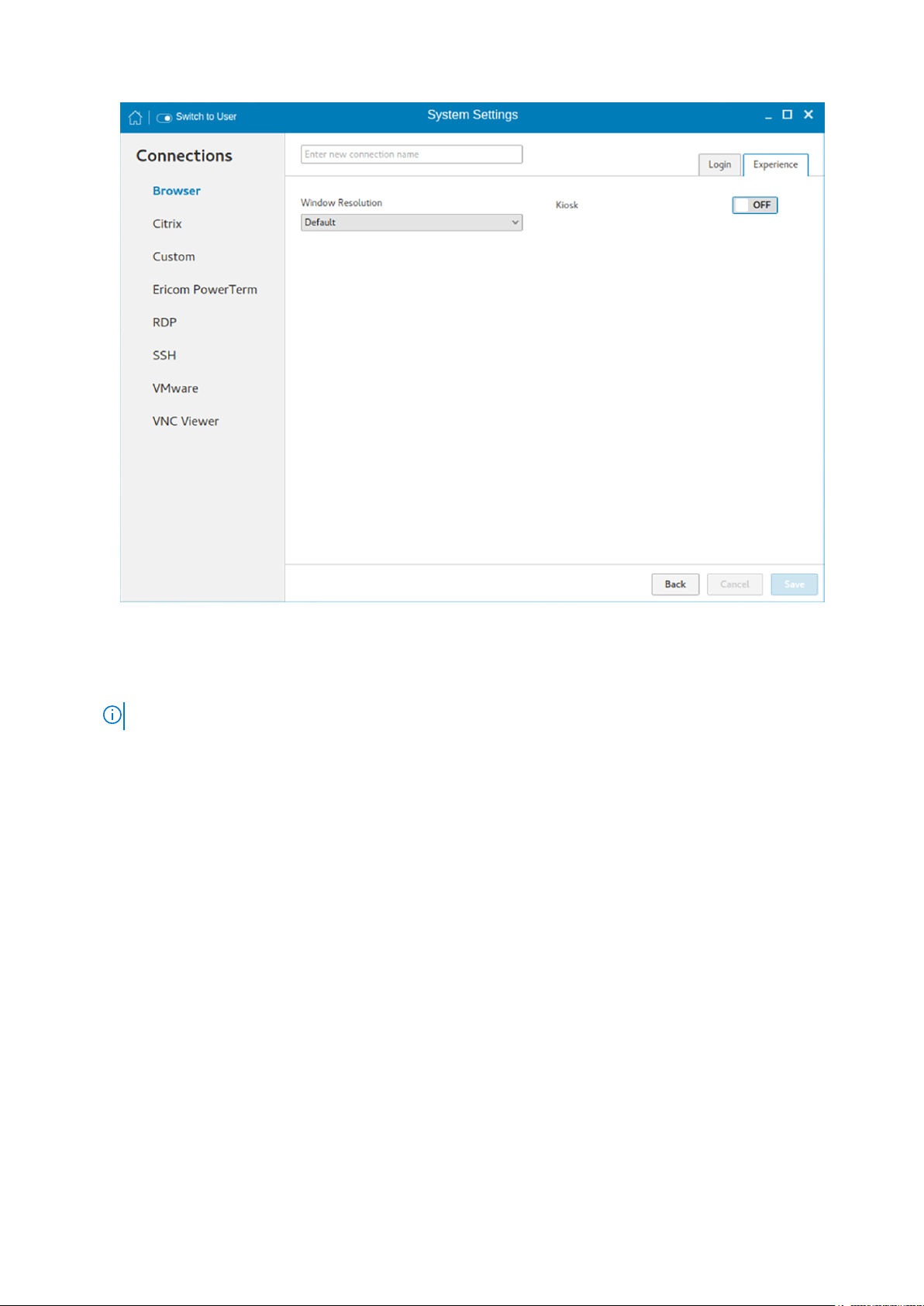
Figure 39. Browser connection experience settings
a. From the drop-down list, select the window resolution you want to set for your Browser window.
b. Click the Kiosk button to enable the Kiosk mode for your browser.
NOTE: When the Kiosk is Enabled, you cannot change window resolution.
7. Click Save to save the changes.
The browser connection created by you is displayed in the Browser Connections list.
To manage a Browser connection:
1. Hover the mouse over a particular browser connection name. The Edit, Remove, and Connect options are displayed next to
the browser connection name.
2. Click Edit to edit the URL address and other settings of the browser connection.
3. Click Remove to remove the browser connection from the list.
4. Click Connect to connect to the URL address you have specified for your browser connection. The webpage opens on your
default browser.
Managing browser global settings
The Manage Browser Global Settings page enables you to configure browser settings for Mozilla Firefox and Google Chrome.
To configure the browser global settings, do the following:
1. Click the Manage Browser Global Settings icon.
The Manage Browser Global Settings page is displayed.
2. Configure your browser settings based on the requirement.
● If you are using Firefox, configure any of the following options:
58
Configuring Connections locally
Page 59

Figure 40. Firefox settings
Table 7. Mozilla Firefox settings
Parameter Description
Hide Bookmark Click the ON/OFF button to enable or disable this option. If
this option is enabled, the bookmark bar is not displayed on
the web page.
By default, this option is enabled.
Hide Downloads Click the ON/OFF button to enable or disable this option. If
this option is enabled, the downloaded items are is not
displayed on the web page.
By default, this option is enabled.
Hide History Click the ON/OFF button to enable or disable this option. If
this option is enabled, the browser history is not displayed on
the web page.
By default, this option is enabled.
Clear Browser Data Click the ON/OFF button to enable or disable this option. If
this option is enabled, the browser data is removed.
By default, this option is disabled.
Disable About:Config Click the ON/OFF button to enable or disable this option. If
this option is enabled, the Configuration Editor is disabled
and you cannot configure the Firefox preferences.
By default, this option is enabled.
Configuring Connections locally 59
Page 60

Table 7. Mozilla Firefox settings (continued)
Parameter Description
Disable About:Add-ons Click the ON/OFF button to enable or disable this option. If
this option is enabled, the Add-ons Manager tab is disabled
and you cannot configure the add-ons.
By default, this option is enabled.
Disable About:Preferences Click the ON/OFF button to enable or disable this option. If
this option is enabled, the Preferences\Settings Editor is
disabled and you cannot configure the Firefox preferences.
● If you are using Google Chrome, configure any of the following options:
Table 8. Google Chrome settings
Parameter Description
Hide Bookmark Click the ON/OFF button to enable or disable this option. If this
option is enabled, the bookmark bar is not displayed on the web
page.
By default, this option is enabled.
Hide Downloads Click the ON/OFF button to enable or disable this option. If this
option is enabled, the downloads are not displayed on the web
page.
By default, this option is enabled.
Hide History Click the ON/OFF button to enable or disable this option. If this
option is enabled, the browser history is not displayed on the
web page.
By default, this option is enabled.
Clear Browser Data Click the ON/OFF button to enable or disable this option. If this
option is enabled, the browser data is removed.
By default, this option is disabled.
3. Click Save to save the settings.
Configuring and managing Citrix connections
The Citrix Connections page enables you to create and manage Citrix connections both locally and globally.
To configure the local Citrix settings:
1. Click the + icon to add a new Citrix Connection.
The Citrix Connections page is displayed.
2. Enter the name of the Citrix connection for which you will specify the Server URL address.
3. From the Connection Type drop-down list, select any of the following connection type. For more information, see
Configuring the server connection type
● Server
● Published Application
● Storefront
4. Click Save to save the changes.
60
Configuring Connections locally
Page 61

Configuring the server connection type
If Server is selected as the Connection type, the following options must be configured in the Login tab.
Figure 41. Citrix connection login settings
Table 9. Server
Parameter Description
Browsing Protocol From the drop-down list, select your preferred Browsing
Protocol.
Citrix Server Enter the specific Citrix Server.
Username Enter the Username of the server.
Password Enter the Password of the server.
Domain Enter the preferred Domain for the server connection.
Ping before connect Click the ON/OFF button to enable or disable this option. If
enabled, the connection is checked before connecting to a
session.
Auto-Connect after login Click the ON/OFF button to enable or disable this option. If
enabled, the connection is automatically established after you
log in to your thin client.
Auto-Reconnect after disconnect Click the ON/OFF button to enable or disable this option. If
enabled, the connection is automatically established after you
disconnect from the session.
Configuring Connections locally 61
Page 62

Table 9. Server (continued)
Parameter Description
When disconnect, reconnect Select the time duration in seconds to delay the reconnection
attempt after a disconnection occurs.
Smartcard login
Smartcard type This field is enabled when you select Smart Card Login.
Application command line Enter the command line for the program on the server.
Serial number Enter the serial number for environments that require the
Working directory
Click the Show advance settings to view and configure the advanced options for your Citrix server connection.
NOTE:
The advanced options are available only for server connections.
Click the ON button to enable smart card login to the thin
client. The User Name, Password, and Domain are not
required.
NOTE: Smart Card Login is applicable only for Server and
Storefront Connections
Select the type of smart card you are using from the dropdown list.
thin client license serial number.
Enter the working directory for the program.
NOTE:
Working Directory is applicable only for Server
Connections.
Table 10. Advanced options
Parameter Description
Alternate Firewall From the drop-down list, Select Yes to use an alternate
address for firewalls.
Auto-detect proxy Click the ON button to automatically detect the proxy type.
Click the OFF button to manually enter the proxy type.
Proxy type From the drop-down list, Select a proxy type.
Proxy Address From the drop-down list, Select a proxy address.
NOTE: If you select Secure (HTTPS) or SOCKS as the
Proxy Type, you must enter the Proxy Address and Port.
If Published Application or Storefront is selected as the Connection Type, the following options must be configured in
addition to the options listed for Server Connections Table.
Store Name—Enter your preferred store name. Multiple store names are not supported.
NOTE:
● SmartCard Login option is not available for Published applications.
● The Storefront option is applicable only for Citrix XenDesktop 7.0 and later versions. Select this option to specify the
name of a Store Front server to display the applications available in that sever.
● Smart card type option is not applicable for Server connections.
The following options must be configured in the Experience tab.
62
Configuring Connections locally
Page 63

Figure 42. Citrix connection experience settings
Table 11. Experience
Parameter Description
Windows resolution Select the Windows resolution that you want to use on your
monitor. The available resolutions are:
Default
640 X 480
800 X 600
1024 X 768
1280 X 1024
1600 X 1200
Full Screen
Colors Specifies the number of colors to display for each pixel. Select
the session color mode to get the faster display performance
on your monitor. The available options are:
256
Best quality (64k)
16 million
Encryption Specifies the connection security level. Select the preferred
option.
Basic
RC5 (128 bit-login only)
Configuring Connections locally 63
Page 64

Table 11. Experience (continued)
Parameter Description
RC5 (40-bit)
RC5 (56-bit)
RC5 (128-bit)
NOTE:
● The highest level is 128-bit security and the lowest
level is Basic.
● Only Basic, and RC5 128-bit support Citrix XenDesktop
7.15. RC5 40-bit, and RC5 56-bit support Citrix
XenDesktop 7.15 and earlier versions. RC5 40-bit and
RC5-56 bit support has been deprecated since
XenDesktop 7.9.
Enable middle button paste login Click the ON/OFF button to enable or disable this option. If
enabled, you can use the mouse middle click to paste content
into your text documents.
Compression Click the ON/OFF button to enable or disable this option.
Optimize for low bandwidth Click the ON/OFF button to enable or disable this option.
Sound Click the ON/OFF button to enable or disable this option.
Configuring Global Citrix settings
When you log out and log in, you are prompted for credentials to log in to a Citrix session for the selected domain.
When you successfully log in, all the applications and desktops on the remote session are listed on the local desktop.
1. Click Manage Citrix Global Settings.
The Manage Citrix Global Settings page is displayed.
2. On the Login tab, configure the following options to enable Citrix PAM login and enable the PAM login using the slider, in the
Managing PAM login page. The Domain details also need to be provided on the Managing PAM login page.
64
Configuring Connections locally
Page 65

Figure 43. Citrix global login settings
a. Enter the Citrix server.
b. From the drop-down list, select the required browsing protocol. The available options are:
● TCP/IP + HTTP server location
● TCP/IP
● SSL/TLS + HTTPS server location
c. Enter the store name.
d. Click Show Advance Settings to view and configure the advanced options.
i. Click the ON/OFF button to enable or disable the Use Alternate address for firewall option. If enabled, an alternate
address can be used for firewall configuration.
ii. Click the ON button to automatically detect the proxy type or click the OFF button to manually enter the proxy type.
iii. From the drop-down list, select a proxy type
3. On the Experience tab, configure the following options.
Configuring Connections locally
65
Page 66

Figure 44. Citrix global experience settings
a. Click the ON/OFF button to enable or disable the Application Reconnection option. If enabled, the connection is
automatically re-established after you disconnect from the session.
b. Select the Windows resolution you can use to get the best display on your monitor.
c. If you come across over-scrolling when using certain published applications, increase the adjustment by 100 until the
display improves.
NOTE: The maximum scroll adjustment is 1000.
d. Click the ON/OFF button to enable or disable the PrintScreen option. Select the option to use the Print Screen key to
capture an image of the desktop to the Clipboard.
e. Use this section to map hotkeys on the thin client.
From the drop-down list, select the preferred keyboard shortcuts.
● If you select Direct option for handling keyboard shortcuts, then from the drop-down list, Select the direct key to
handle keyboard shortcuts.
● If you select Direct in Full Desktops only or Translated option for handling keyboard shortcuts, then complete the
following steps:
i. Click the Hotkeys tab to map hotkeys on the thin client.
ii. Select a Hotkey option using the Hotkey lists for each function you want.
4. Click the Peripherals tab, and configure the following options:
66
Configuring Connections locally
Page 67

Figure 45. Drive mapping
a. Drive Mapping:
● Dynamic Mapping—Dynamic client drive mapping enables virtual desktops to access mass storage devices, such as
USB flash drives, configured on the endpoint. The virtual (not local) desktop is responsible for controlling USB drives
and displaying them in the user interface. When a USB drive is connected to an endpoint, it is automatically mounted
and freely accessible. USB drives accessed using dynamic client drive mapping are treated as network drives. For this
reason, you cannot check, reformat, or perform other local operations on them.
Configuring Connections locally
67
Page 68

Figure 46. Dynamic mapping
● Mapping all devices—This option is same as Dynamic mapping but the you will be given an option to select the drive
letter and read-write permissions for the drives. When this option is enabled all the usb storage devices which are
mounted on /run/media/ will be mapped to the Citrix session. You are provided the option to choose the drive letter
and read or write permissions for the drives which have been mounted on to the thin client. The device name value
remains constant as /run/media/.
68
Configuring Connections locally
Page 69

Figure 47. Mapping all devices
● Mapping a single device—Unlike the previous two options, this option enables you to select an individual device
that should be redirected to the session. The device name lists all the devices that has been successfully mounted on
to the thin client. You will be able to select a drive letter and read-write permission for individual drives that redirect
to the session.
Configuring Connections locally
69
Page 70
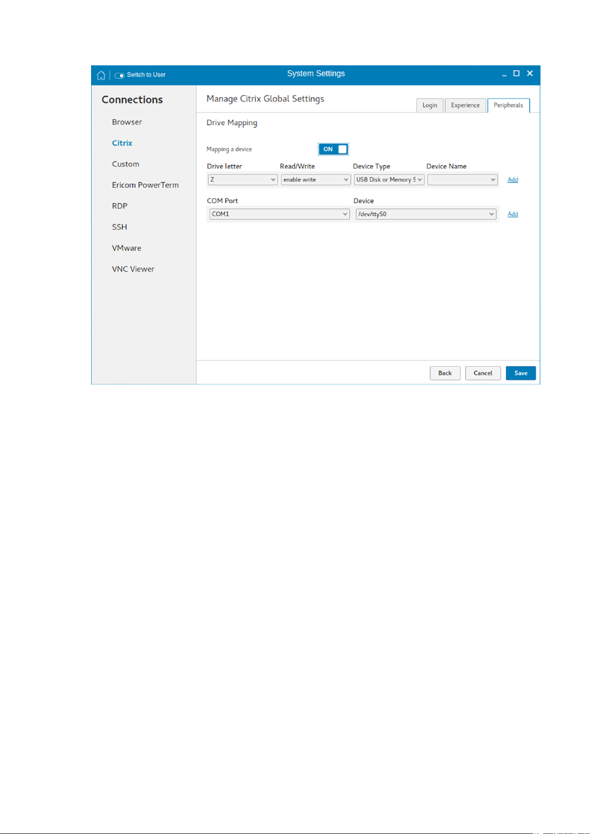
Figure 48. Mapping a device
To add a COM port, complete the following task:
a. Click Add.
b. From the COM Port list, select a COM port—1 to 4.
c. Select a device from the device list.
To delete a COM port, click the X icon next to the COM port that you want to delete.
5. Click Save to save the changes.
Managing PAM login
1. Click PAM Login.
The Manage PAM Login Settings page is displayed. The PAM login page displays the settings that are used for PNAgent
server connection. It allows you to enable or disable the PAM login, and to enter the domain for PNAgent server.
2. Click the ON/OFF button to enable Citrix PAM login option.
3. Click the ON/OFF button to enable or disable the Show All Apps option.
4. Enable the Enable Citrix PAM login option to enter the Citrix server domain.
The Citrix Global Settings table provides you the information about Citrix server, protocol, and Store Name and you are
restricted from editing the content.
5. Click Save to save the changes.
Citrix ICA Client RTME
ThinLinux supports HDX RealTime Media Engine (RTME) 2.7. For more information about the Citrix RTME 2.7 features, see the
HDX RealTime Media Engine for Microsoft Skype for Business article at www.citrix.com.
70
Configuring Connections locally
Page 71

Citrix Workspace App
ThinLinux supports Citrix Workspace App on both on-premises and cloud environments. Citrix Workspace App enables you to
access all your virtual apps, desktops, and other Citrix products from a single workspace UI. For more information about Citrix
Workspace App, see the Citrix documentation at docs.citrix.com.
Configuring and managing the custom connections
The Custom Connections page enables you to create and manage the Custom connection based on shell commands. The main
Custom page has options to create a Custom connection.
To configure the Custom Settings, complete the following task:
1. Click the + icon to add a new Custom Connection.
The Custom Connections page is displayed.
2. Enter the name of the Custom connection.
3. The following options must be configured in the Login tab.
Figure 49. Custom connection login settings
a. Enter the shell command. The shell command is performed when you click the connection icon on the desktop.
b. Click the ON/OFF button to enable or disable the Auto-connect after login option. If enabled, the connection is
automatically connected after you log in to your thin client.
c. Click the ON/OFF button to enable or disable the Auto-reconnect after disconnected option. If enabled, the connection
is automatically re-connected after you disconnect from the session.
d. Select the time duration in seconds to delay the reconnection attempt after a disconnection occurs.
4. The following options must be configured in the Experience tab.
Configuring Connections locally
71
Page 72

Figure 50. Custom connection experience settings
a. Click the ON/OFF button to enable or disable the Run in terminal window option.
5. Click Save to save the changes.
Configuring and managing the Ericom PowerTerm connections
The Ericom PowerTerm connections page enables you to create and manage the Ericom PowerTerm connections.
To configure the Ericom PowerTerm Connection Settings, complete the following task:
1. Click the + icon to add a new Ericom PowerTerm Connection. The Ericom PowerTerm Connections page is displayed.
2. Enter the name of the Ericom PowerTerm connection.
3. The following options must be configured in the Login tab .
72
Configuring Connections locally
Page 73

Figure 51. Ericom PowerTerm login settings
Figure 52. Ericom PowerTerm login settings
Configuring Connections locally
73
Page 74

Table 12. Ericom PowerTerm login settings
Parameter Description
Connection type On the Connection Type page, click the Network or Serial Port
radio button depending upon the requirement. By default, the
Network option is selected. Serial Port radio button is disabled if the
application does not detect any active serial ports.
Host Enter the Ericom server host’s IP or FQDN address in the Host field.
This field is hidden, if the connection is through Serial Port.
Port Specify the port number used to connect the Ericom server in the
Port field. This is available if the connection is through the network.
In case of Serial Port, this field displays as COM port and the
available serial ports are listed in the drop-down list.
Terminal type Select the terminal type to be emulated from the drop-down list in
the Terminal Type field.
Terminal name Type the name of the Ericom PowerTerm terminal window in the
Terminal Name field
Script file to run on logon Specify the path of the script file (if any) to be executed in the
remote system in the Script file to run on Logon field.
Remote configuration file Specify the location of the remote configuration files in the Remote
configuration file field.
Auto-connect after login
4. The following options must be configured in the Experience tab.
a. Click the ON/OFF button to enable or disable the Auto-connect
after login option. If enabled, the connection is automatically
connected after you log in to your thin client.
b. Click the ON/OFF button to enable or disable the Auto-
reconnect after disconnected option. If enabled, the connection
is automatically re-connected after you disconnect from the
session.
c. Select the time duration in seconds to delay the reconnection
attempt after a disconnection occurs.
74
Configuring Connections locally
Page 75

Figure 53. Ericom PowerTerm experience settings
Table 13. Ericom PowerTerm Experience Settings
Parameter Description
Window size Select the desired terminal window size from the drop-down list
in the Window Size field.
Show menu Click the ON/OFF button to enable or disable this option. It
enables the top menu option on the Ericom PowerTerm window.
Show toolbar Click the ON/OFF button to enable or disable this option. It
enables the toolbar option on the Ericom PowerTerm window.
Show status Click the ON/OFF button to enable or disable this option. It
enables the status bar on the Ericom PowerTerm window.
Show buttons Click the ON/OFF button to enable or disable this option. It
enables the soft buttons on the Ericom PowerTerm window.
Echo locally When the connection is configured through Serial Port then
additional option Echo locally option will be available on the
Experience tab. If this option is set to ON, it will set the local
echo option of the generated Ericom PowerTerm terminal
window.
Configuring Connections locally 75
Page 76
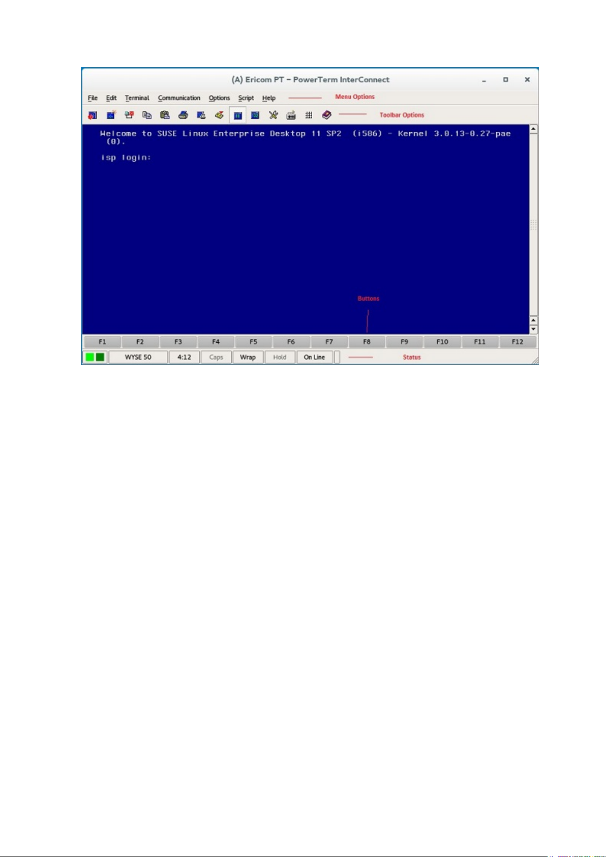
Figure 54. Ericom PT — PowerTerm Interconnect
Configuring and managing RDP connections
The RDP connections page enables you to create and manage the RDP connection. The main RDP page has options to create
an RDP connection and modify existing connections.
To configure the RDP settings, complete the following tasks:
1. Click the + icon to add a new RDP Connection.
The RDP Connections page is displayed.
2. Enter the name of the RDP connection.
3. Configure the following tasks in the Login tab:
76
Configuring Connections locally
Page 77

Figure 55. RDP login settings
Table 14. RDP login settings
Parameter Description
Server Enter the IP address or FQDN of the RDP server to which
you want to establish a connection.
Username Enter the Username to log in to the RDP Server.
Password Enter the Password to log in to the RDP Server.
Domain Enter the Domain to log in to the RDP Server.
Use RD Gateway Select to enable and configure an RD Gateway to connect to
your remote computers, if required by your network
administrator and then do one of the following:
● To configure the RD Server, and then Use Remote
Desktop Credentials for RD Gateway—Enter the RD
Server IP address or URL of the Remote Desktop
Gateway server, and then select the Use Remote
Desktop credentials for RD Gateway check box, if the
server credentials are the same credentials as your RDP
host remote computer credentials.
● To configure the RD Server, and then Manually enter RD
User Name, RD Password, RD Domain—Enter the RD
Server IP address or URL of the Remote Desktop
Gateway server. Clear the Use Remote Desktop
credentials for RD Gateway check box and then manually
enter the Username, Password, and Domain of the RD
Gateway server, if required.
Configuring Connections locally 77
Page 78

Table 14. RDP login settings (continued)
Parameter Description
NOTE: An RD Gateway server is a type of gateway that
enables authorized users to connect to remote
computers on a corporate network from any computer
with an Internet connection. An RD Gateway server
enables Remote Desktop connections to a corporate
network from the Internet without having to set up
virtual private network (VPN) connections. Ask your
network administrator whether you need to specify an
RD Gateway server.
Remote Application Enter the Remote Application name.
Application Command Line Enter the command line for the program on the server.
Working Directory Enter the Working Directory for the program.
NOTE: Working Directory is applicable only for Server
Connections.
Ping Before Connect Click the ON/OFF button to enable or disable this option. If
enabled, the connection is checked before connecting to a
session.
Auto-Connect after login Click the ON/OFF button to enable or disable this option. If
enabled, the connection is automatically established after
you log in to your thin client.
Auto-reconnect after disconnect Click the ON/OFF button to enable or disable this option. If
enabled, the connection is automatically re-established after
you disconnect from the session. If the Auto-reconnect
option is enabled, you must enter the Delay duration (in
seconds) when you reconnect to the session. The default
time duration is 30 seconds.
Notify when disconnected Click the ON/OFF button to enable or disable this option. It
notifies when the connection is disconnected.
Network Level Authentication (NLA) Click the ON/OFF button to enable or disable this option.
Enable the Network Level Authentication (NLA), if NLA is
enabled on your remote computer. Your remote computer
requires NLA user authentication before you establish a full
Remote Desktop connection and the login screen is
displayed.
Smart card login Click the ON/OFF button to enable smart card login to the
thin client. The User Name, Password, and Domain are not
required.
Enable H.264 decoding Click the ON/OFF button to enable or disable this option.
Enable this option to allow H.264 decoding in Microsoft RDP
Client. The RDP client uses H.264 decoding, provided the
agent supports H.264 software encoding. If the agent does
not support H.264 software encoding, the RDP client uses
JPG/PNG decoding. Disable this option if you want to use
JPG/PNG decoding.
Enable UDP networking Click the ON/OFF button to enable or disable this option.
Enable this option to allow UDP networking in Microsoft
RDP Client. The RDP client uses UDP networking, provided
78 Configuring Connections locally
Page 79

Table 14. RDP login settings (continued)
Parameter Description
UDP connectivity is available. If the UDP networking is
blocked, the RDP client uses TCP networking. Disable this
option to use TCP networking.
4. The following options can be configured in the Experience tab.
Figure 56. RDP experience settings
Table 15. RDP Experience Settings
Parameter Description
Window Resolution Select the Windows resolution you can use to get the best
display on your monitor. The available options are:
Default
640 X 480
800 X 600
1024 X 768
1280 X 1024
1600 X 1200
Full Screen
Colors Specifies the number of colors to display for each pixel.
Select the session color mode to get the faster display
performance on your monitor. The available options are:
High Color (15-bit)
Configuring Connections locally 79
Page 80

Table 15. RDP Experience Settings (continued)
Parameter Description
High Color (16-bit)
True Color (24-bit)
Best Quality (32-bit)
Speed Level Select a speed level to describe the network connection.
● Modem
● Broadband
● LAN
● Custom
Sounds Select the relevant option from the drop-down list. You can
choose to redirect the audio on the remote session to the
local device, or not allow the audio to play on the remote
session on the local device, or leave the audio playing on the
remote session.
● Off
● Local
● Remote
Encryption Level Select an encryption level, either Normal or None.
For servers with data encryption settings, you must select
Normal for the encryption level.
Wallpaper Click the ON/OFF button to enable or disable this option.
Font Smoothing Click the ON/OFF button to enable or disable this option.
Menu and Window Animation Click the ON/OFF button to enable or disable this option.
Remote FX Click the ON/OFF button to enable or disable this option.
Show window content while dragging Click the ON/OFF button to enable or disable this option.
This option shows the window content when the user drags
the window on screen.
Subsampling Click the ON/OFF button to enable or disable this option. It
enables color space conversion required for Chroma
subsampling.
Chroma Subsampling is the practice of encoding/
compressing images for a higher transmission experience.
Grab Keyboard Events Click the ON/OFF button to enable or disable this option. It
enables all keyboard events within the connection window to
be sent to the connection’s applications.
Compression Click the ON/OFF button to enable or disable this option.
Low Bandwidth Click the ON/OFF button to enable or disable this option. If
enabled, following options are automatically disabled:
Wallpaper
Font Smoothing
Menu and Window Animation
Remote FX—This feature will be supported in next release.
80 Configuring Connections locally
Page 81

Table 15. RDP Experience Settings (continued)
Parameter Description
Show window content while dragging
Subsampling
Enables low-bandwidth optimization.
NT4 Compatible Click the ON/OFF button to enable or disable this option.
5. Configure the following tasks in the Peripherals tab.
Figure 57. RDP peripherals settings
● Drive Mapping: Drive mapping tab is used to share map names on the server to USB mass storage devices attached to
the thin client, and to view and manage the list of current server share names including the drive information mapped on
the thin client.
a. Enter the share name.
b. The list includes the available drives.
c. The Base path is an entry to a directory within the drive.
d. Click the ON/OFF button to enable or disable the Redirect all USB drives to folders in Share named ‘WyseUSB’ option. If
enabled, it redirects all USB drives to folders in Share name WyseUSB. You can redirect all your USB drives such as USB
Floppy, USB CDROM, USB Disk or Memory stick, and local or mounted disk to the folders in share name WyseUSB and if
this is enabled Individual Drive Mapping is disabled.
● Device Mapping: Device mapping tab is used to map devices to ports on the thin client, and to view and manage the list
of current devices that are mapped on the thin client.
a. Select your preferred port devices.
b. Click the ON/OFF button to enable or disable the Forward Printers option.
6. Click Save to save the changes.
Configuring Connections locally
81
Page 82

Configuring and managing the SSH connections
The SSH connections page enables you to create and manage the SSH connections. The main SSH connections page has
options to create an SSH connection.
To configure the SSH connection, complete the following task:
1. Click the + icon to add a new SSH Connection.
The SSH Connections page is displayed.
2. Enter the name of the SSH connection.
Figure 58. SSH connection settings
3. Enter the IP address or FQDN of the SSH server that you want to connect.
4. Enter the Username to log in to the remote SSH Server.
5. Enter the command to run the program.
6. Click the ON/OFF button to enable or disable the Auto-connect after login option. If enabled, the connection is
automatically connected after you log in to your thin client.
7. Click the ON/OFF button to enable or disable the Auto-reconnect after disconnected option. If enabled, the connection is
automatically re-connected after you disconnect from the session.
8. Select the time duration in seconds to delay the reconnection attempt after a disconnection occurs.
9. Click Save to save the changes.
Configuring and managing VMware connections
The VMware connections page enables you to create and manage the View client 3.5 connections.
To configure the VMware settings, complete the following task:
1. Click the + icon to add a new VMware Connection.
82
Configuring Connections locally
Page 83

The VMware Connections page is displayed.
2. Enter the name of the VMware connection.
3. Configure the following options in the Login tab.
Figure 59. VMware connection login settings
Table 16. Login
Parameter Description
Host Enter the hostname or IP address or FQDN of the Horizon
of the VMware View Server.
Port Enter the port number of the host.
Protocol From the drop-down list, select the specific protocol. The
available options are:
● PCOIP
● RDP
● Blast
Username Enter the User ID that is used to log in to the remote
Horizon server.
Password Enter the password that is used to log in to the remote
Horizon server.
Domain Enter the Domain name. It is used to log in the remote
Horizon server.
Configuring Connections locally 83
Page 84

Table 16. Login (continued)
Parameter Description
Username with Domain Click the ON/OFF button to enable or disable this option.
If enabled, specify the domain along with user name.
Unauthenticated Access Click the ON/OFF button to enable or disable this option.
If enabled, specify the unauthenticated access username.
Password and domain credentials are not required.
Enable interactive mode Click the ON/OFF button to enable or disable this option.
If enabled, then after a successful connection to the server,
it displays all the published application and desktop icons.
You can start the applications or desktop sessions based on
your choice
If disabled, then the Published Applications option is enabled
in the Login tab, and selecting that option enables you to
directly start the application or desktop that you specify.
Ping before connect Click the ON/OFF button to enable or disable this option. If
enabled, it pings the connection is checked in server IP/
FQDN before connecting to a session.
Enable NLA This option is available to configure when you select the
protocol as RDP. Click the ON/OFF button to enable or
disable this option. Enable the Network Level Authentication
(NLA), if NLA is enabled on your remote computer. Your
remote computer requires NLA user authentication before
you establish a full Remote Desktop connection and the
login screen is displayed.
Secure connection Click the Secure Preferences tab and select any of the
options that determine how the client should proceed when
it cannot verify that your connection to the server is secure.
Published Application Click the ON/OFF button to enable or disable this option.
If enabled, specify the Published Application name.
If disabled, specify the Published desktop name.
Desktop If interactive mode is disabled, you can specify Published
desktop name.
Application If interactive mode is disabled, you can specify Published
application name.
4. The following options must be configured in the Experience tab.
84
Configuring Connections locally
Page 85

Figure 60. VMware connection experience settings
Table 17. Experience
Parameter Description
Windows resolution Select the Windows resolution that you want to get the best
display on your monitor. The available resolutions are:
Use All Monitors
Full Screen
Large Screen
Small Screen
1024 X 768
800 X 600
640 X 480
AutoReconnect after disconnect Click the ON/OFF button to enable or disable this option. If
enabled, the connection is automatically reestablished after
you disconnect from the session.
Delay (seconds) before reconnect Select the time duration in seconds to delay the
reconnection attempt after a disconnection occurs.
sslProtocol Use the SSL protocol to securely connect to a web server
over the insecure internet.
sslCipher Use the SSL Cipher suite to secure your SSL connection.
Configuring Connections locally 85
Page 86

Table 17. Experience (continued)
Parameter Description
Enable fullscreen Click the ON/OFF button to enable or disable this option.
Select this option to view the remote session in full screen
mode in all the monitors.
Disable fullscreen drop-down menu bar Click the ON/OFF button to enable or disable this option.
Select this option to disable the drop-down menu bar in the
full screen mode.
Disable exit on the disconnect Click the ON/OFF button to enable or disable this option.
Select this option if you do not want the Horizon server to
retry connecting if there is a connection error. You can
typically select this option if you use kiosk mode.
Autoconnect after login Click the ON/OFF button to enable or disable this option.
Select this option to reconnect automatically after a
disconnection occurs.
Lock server URL/Host field Click the ON/OFF button to enable or disable this option.
Enable MMR Click the ON/OFF button to enable or disable the
multimedia redirection (MMR) feature. If enabled, the
multimedia stream is processed on the thin client using a
virtual channel.
Enable H.264 decoding Click the ON/OFF button to enable or disable this option.
Select this option to enable H.264 decoding in Horizon
Client. When this option is selected (the default setting),
Horizon Client uses H.264 decoding, if the agent supports
H.264 software encoding. If the agent does not support
H.264 software encoding, Horizon Client uses JPG/PNG
decoding. Deselect this option to always use JPG/PNG
decoding. This option is applicable only for VMware Blast
protocol and RDP protocol.
Allow H.264 High Color Accuracy Click the ON/OFF button to enable Horizon Client to use a
superior color fidelity when H.264 decoding is enabled
Auto Hide Toolbar Click the ON/OFF button to hide or display the tool bar.
Display Scaling Click the ON/OFF button of this option to enable the
remote desktops and applications to use the device scaling
setting and appear normal-sized when using displays with
high resolution.
5. Configure the following options in the Peripherals tab:
86
Configuring Connections locally
Page 87

Figure 61. VMware connection peripherals settings
Table 18. Peripherals
Parameter Description
Click the ON/OFF button to enable or disable this option.
Select this option if you want to automatically connect your
Automatically Connect USB when inserted
Automatically Connect USB at Startup Click the ON/OFF button to enable or disable this option.
Allow Access to Removable Storage Click the ON/OFF button to enable or disable this option.
6. Click Save to save the settings.
USB drive to the thin client after you plug-in the USB drive.
Select this option if you want to automatically connect your
USB drive to the thin client when you start the system.
Select this option if you want to permit access to use
removable storage devices.
Configuring and managing the VNC viewer connections
The VNC Viewer connections page enables you to create and manage the VNC connections. The main VNC connections page
has options to create a VNC connection.
To configure the VNC Viewer Settings, complete the following task:
1. Click the + icon to add a new VNC connection. The VNC Viewer Connections page is displayed.
2. Enter the name of the VNC connection.
Configuring Connections locally
87
Page 88

3. The following options must be configured in the Login tab.
Figure 62. VNC viewer login settings
Table 19. VNC viewer login settings
Parameter Description
Host Enter the IP address or FQDN of the VNC server which you
want to connect.
Password Enter the password to log in to the remote VNC Server.
Auto-connect after login Click the ON/OFF button to enable or disable this option. If
enabled, the connection is automatically connected after you
log in to your thin client.
4. The following options must be configured in the Experience tab.
88
Configuring Connections locally
Page 89

Figure 63. VNC viewer experience settings
Table 20. VNC viewer experience settings
Parameter Description
Colors Specifies the number of colors to display for each pixel.
Select the session color mode to get the faster display
performance on your monitor. The available options are:\
● True color (full color)
● 8 colors (very low)
● 64 colors (low)
● 256 colors(medium)
JPEG quality From the drop-down list, select the preferred value. The
range for JPEG quality is 0-9, with 0 being poor quality and
9 being the best quality.
Compression level From the drop-down list, select the preferred value. The
range for compression level is 1–6. The 1 value explains the
fast quality and 6 value explains the best quality.
Full screen Click the ON/OFF button to enable or disable this option. If
enabled, the connection is started in the full screen mode.
It is not in the kiosk mode, click the standard VNC viewer f8
key to exit the full screen mode.
Shared Click the ON/OFF button to enable or disable this option. If
enabled, the connected desktop is in share mode.
Configuring Connections locally 89
Page 90

Table 20. VNC viewer experience settings (continued)
Parameter Description
View only Click the ON/OFF button to enable or disable this option. If
enabled, the connection is in view-only mode. Mouse and
keyboard input to the remote machine is disabled.
5. Click Save to save the changes.
Starting VDI session without login credentials
To start a VDI session without entering the login credentials, do the following:
1. Create a VDI connection with the following values:
● Set the username as $UN.
● Set the password as $PW.
● Set the domain name as $DN.
2. Log in as a domain user.
3. Launch the session.
You will not be prompted to enter the username and password.
Zoom application for VDI
The Zoom application for VDI is a Unified Communications solution that is offered by Zoom for virtual deployments. It supports
enterprise video conferencing and screen sharing on the virtual desktops. Zoom offloads media processing from the virtual
desktop server to the thin client. All audio and video signals are routed directly between the endpoints. You can use the Zoom
application to make and receive calls in the VDI session.
NOTE: To enable webcam support for Zoom in a Citrix session, install GStreamer and other dependency packages.
For more information about using the Zoom application in a VDI session, see the Quick Start Guides at support.zoom.us.
90
Configuring Connections locally
Page 91

Security settings
On the System Settings page, click the Security icon. The following tabs are listed on the left pane of the System Settings
page.
● Accounts
Certificates
●
● Firewall
● SSH Server
● VNC
Managing the accounts settings
The accounts management page is available in the admin mode only.
5
Figure 64. Accounts settings
To manage the account settings, configure the following options:
1. Auto Login—Click the ON/OFF button to enable or disable the Auto Login option. If you enable this option, the thin client
is automatically logged in without any user intervention.
2. Change thinuser password—Use this option if you want to change the thinuser password.
3. Change root password—Use this option if you want to change the root password.
4. Enable GRUB menu password protection—Click the ON/OFF button to enable or disable the GRUB menu password
protection. If this option is enabled, you can set the password for the GRUB boot menu to restrict access to specific
operations.
Security settings 91
Page 92

5. Click Save.
6. When prompted, enter the root password, and click OK.
Figure 65. Root password
Managing the certificates
1. Click the + icon to import a new certificate.
The Import Certificate page is displayed.
2. Select the preferred Import Source option.
● Remote Server
● Local Devices
a. Remote server
Figure 66. Import certificates remote server
i. If you select Remote server option, the remote server information is displayed.
92
Security settings
Page 93

i. Enter the Importing server URL. The supported protocols are ftp, http, and https.
ii. Browse the required Certificate File.
iii. Click the ON/OFF button to enable or disable the Sever from default registry option.
ii. User Anonymous: Click the ON/OFF button to enable or disable this option. If disabled, enter the Username and
password required for the server.
b. Local Devices
Figure 67. Import certificates local device
i. Click the Browse tab and navigate to the certificate that you want to use.
ii. Click OK.
c. Click Import to import the certificates.
The installed certificates are shown as, Filename: certificate name.
d. To remove a certificate, move the cursor over it and click Remove.
Configuring the firewall settings
Use the firewall settings page to configure firewall settings.
Security settings
93
Page 94

Figure 68. Firewall settings
To configure the firewall settings on your thin client, do the following:
1. To enable firewall, click the ON/OFF button.
2. Type the firewall configuration script in the text box.
For example, the following iptables commands can be used to disable ping from the thin client or to the thin client:
/sbin/iptables -A OUTPUT -p icmp --icmp-type 8 -j DROP
/sbin/iptables -A INPUT -p icmp --icmp-type 8 -j DROP
3. Click Save.
4. When prompted, click Restart.
The changes are applied after the system reboot.
Managing SSH server preferences
By default, SSH Server is disabled on the thin client. The Managing the SSH server screen is available only in Admin mode. It
enables to configure the SSH server on the thin client.
94
Security settings
Page 95

Figure 69. Manage SSH
Configure the following options:
1. Click the ON/OFF button to enable the Enable SSH option. If enabled, the SSH server starts working.
2. Click the ON/OFF button to enable or disable the Enable SSH Root Login option. When the Enable SSH option is
enabled, the Enable SSH Root Login option is not enabled automatically.
3. Click Save to save the changes.
Setting VNC server preferences
Use the VNC server page to configure the VNC server preferences.
Security settings
95
Page 96

Figure 70. VNC server preferences
To configure the VNC server preferences:
1. Click the ON/OFF button to enable or disable the Enable VNC option.
2. Click the ON/OFF button to enable or disable the confirmation for accessing each VNC connection option.
3. In the Require the user to enter this password field, enter the password. You can enter a maximum eight characters.
4. Click the ON/OFF button to enable or disable the option to show the VNC access warning at the start of the connection.
5. Click Save to save changes.
96
Security settings
Page 97

6
Additional management configurations
On the System Settings page, click the Management icon. The following tabs are listed on the left pane of the System
Settings page.
● Active Directory
Configuration
●
● HAgent
● INI
● Logs and Tools
● SCEP
● Wyse Device Agent
Active Directory
ThinLinux enables you to securely connect to the work domain using the Active Directory credentials. Active Directory enables
an administrator to enable or disable the user authentication to specific domains. You can either join the terminal to the domain,
or use the INI parameter to authenticate the user from Active Directory without joining the terminal.
Prerequisites
● Ensure that the DNS server is configured correctly on the thin client.
● Ensure that the date and time of your thin client are synchronized with the date and time of the domain server.
Figure 71. Active Directory
To join your thin client to a domain, do the following:
Additional management configurations 97
Page 98

1. In the Domain Name field, enter the FQDN of the domain.
2. In the User Name field, enter the name of the user who has the relevant permission to add a computer account to Active
Directory.
3. In the Password field, enter the password for the domain.
4. In the OU field, enter the name of the organizational unit that is associated with the thin client's domain membership. This is
an optional step.
5. Click Join.
A green tick is displayed in the Domain Join Status section, indicating that the domain join is successful.
6. Disable the autologin option, and restart the thin client.
The domain name is displayed on the ThinLinux login screen.
7. Enter the domain user name and password to log in to the ThinLinux desktop.
NOTE:
● You should dis-join the domain before initiating factory reset.
● Administrative operation is not enabled under the domain user login. It is enabled only with thin user that is logged in as
an administrator.
Configuration management
You can manage the device configuration stored locally. Use import and export options to deploy the configuration to the other
devices.
1. Click the + icon to import device configuration from provided configuration file. The Import Device configuration page is
displayed and you are prompted to restart the system.
2. Select the preferred Import Source option.
● Remote Server
● USB Device
a. Remote server
Figure 72. Import configuration - Remote server
98
Additional management configurations
Page 99

i. If you select Remote server option, the remote server information is displayed. Enter the Importing file URL. The
supported URLs are ftp, http, and https.
ii. Click the ON/OFF button to enable or disable the Use Anonymous option. If disable, enter the Username and
password required for the server.
iii. Click Import to import the configuration.
b. USB Device
Figure 73. Import configuration - USB device
i. Click the Browse tab.
NOTE: You must insert the USB device to import the files.
ii. Click Import to import the configuration.
3. Click the icon to Export device configuration to a configuration file. The Export device configuration page is displayed.
4. Select the preferred Export Destination option.
●
Remote Server
● USB Device
a. Remote server
i. If you select Remote server option, the remote server information is displayed. Enter the Configuration file, and
export server URL. The supported URLs are ftp, http, and https.
ii. Click the ON/OFF button to enable or disable the Use Anonymous option. If disable, enter the Username and
password required for the server.
iii. Click Export to export the configuration.
b. USB Device
i. Click the Browse tab. Use the folders and command buttons to find and specify the export path and file you want to
use.
ii. Click OK.
5. Click the icon to Reset to factory defaults.
Additional management configurations
99
Page 100

A warning message is displayed. If you click OK, the system is automatically restarted. Resetting to factory defaults affects
only configuration, it will not uninstall or reinstall add-ons that are different than the factory image.
HAgent
WDM is a device management solution which helps you to manage cloud clients securely from remote infrastructure. WDM
management solution involves both server and client components where client software also known as HAgent should be
installed on each thin client device for management through WDM.
Figure 74. Wyse Device Manager - HAgent
1. Enter the Wyse Device Manager Server name in input box.
2. The following options can be configured. This is an admin only configuration in the thin client.
Table 21. Wyse Device Manager Server
Parameter Description
Enable Auto Device Discovery Click the ON/OFF button to enable or disable this option.
This option enables or disables the discovery of Thin Clients
by DNS Hostname , DNS SRV record Lookup , DHCP option
Tags.
DNS Hostname Click the ON/OFF button to enable or disable this option.
This option will take effect if Enable Auto Device
Discovery is in OFF state. When this option is in ON state,
then the clients are discoverable using DNS Host name.
DNS SRV record Lookup Click the ON/OFF button to enable or disable this option.
100 Additional management configurations
 Loading...