


Dell T7400, YT583 User Manual

Dell Precision™ T7400 User’s Guide
Model DCDO
www.dell.com | support.dell.com

Notes, Notices, and Cautions
NOTE: A NOTE indicates important information that helps you make better use of
your computer.
NOTICE: A NOTICE indicates either potential damage to hardware or loss of data
and tells you how to avoid the problem.
CAUTION: A CAUTION indicates a potential for property damage, personal injury,
or death.
____________________
Information in this document is subject to change without notice.
© 2007 Dell Inc. All rights reserved.
Reproduction in any manner whatsoever without the written permission of Dell Inc. is strictly
forbidden.
Trademarks used in this text: Dell, the DELL logo, Inspiron, Dell Precision, and Dell OpenManage
are trademarks of Dell Inc.; Intel and Xeon are registered trademarks of Intel Corporation; Microsoft,
Windows, and Windows V ista are either trademarks or registered trademarks of Microsoft Corporation
in the United States and/or other countries.
Other trademarks and trade names may be used in this document to refer to either the entities claiming
the marks and names or their products. Dell Inc. disclaims any proprietary interest in trademarks and
trade names other than its own.
Model DCDO
August 2007 P/N YT583 Rev. A00

Contents
1 Finding Information . . . . . . . . . . . . . . . . . 13
2 About Your Computer . . . . . . . . . . . . . . . 21
Front View of the Computer . . . . . . . . . . . . . . . 21
Back View of the Computer
Back Panel Connectors . . . . . . . . . . . . . . . . . 24
Inside View
System Board Components
Specifications . . . . . . . . . . . . . . . . . . . . . . 29
. . . . . . . . . . . . . . . . . . . . . . . 26
. . . . . . . . . . . . . . . 23
. . . . . . . . . . . . . . . 27
3 Advanced Features . . . . . . . . . . . . . . . . . 35
LegacySelect Technology Control . . . . . . . . . . . 35
Manageability
Alert Standard Format
Dell OpenManage™ IT Assistant
Dell OpenManage Client Instrumentation . . . . . 37
Power Management
About RAID Configurations
RAID Level 0
RAID Level 1
. . . . . . . . . . . . . . . . . . . . . . 35
. . . . . . . . . . . . . . . 35
. . . . . . . . . 37
. . . . . . . . . . . . . . . . . . . 37
. . . . . . . . . . . . . . . 39
. . . . . . . . . . . . . . . . . . . . 40
. . . . . . . . . . . . . . . . . . . . 41
Contents 3

RAID Level 5 . . . . . . . . . . . . . . . . . . . . 41
RAID Level 10 . . . . . . . . . . . . . . . . . . . . 43
Configuring Your Computer for RAID
. . . . . . . . 44
RAID Configuration Utility
Entering the RAID Configuration Utility
Navigating Within the Configuration Utility
RAID Configuration and Management
Exit Screen
. . . . . . . . . . . . . . . . . . . . . 45
. . . . . . . . . . . . . . . . 44
. . . . . . 44
. . . . 44
. . . . . . . . . 44
Performing Configuration Tasks . . . . . . . . . . . . . 45
Creating a RAID Level 0 Configuration
. . . . . . . 45
Creating a RAID Level 1 Configuration . . . . . . . 46
Creating a Second RAID Volume
Viewing RAID Volume Properties
. . . . . . . . . . 47
. . . . . . . . . 47
Synchronizing a RAID Volume (Virtual Disk) . . . . 48
Activating a RAID Volume
Deleting a RAID Volume
. . . . . . . . . . . . . 48
. . . . . . . . . . . . . . 48
Replacing and Rebuilding a Degraded RAID Volume 49
4 Setting Up Your Computer . . . . . . . . . . . . 51
Installing Your Computer in an Enclosure . . . . . . . 51
Connecting to the Internet
Setting Up Your Internet Connection
. . . . . . . . . . . . . . . . 53
. . . . . . . . 54
4 Contents
Transferring Information to a New Computer
®
Microsoft
Microsoft Windows Vista™
Power Protection Devices
Surge Protectors
Line Conditioners
Windows® XP . . . . . . . . . . . . . 56
. . . . . . . . . . . . 59
. . . . . . . . . . . . . . . 59
. . . . . . . . . . . . . . . . . . 60
. . . . . . . . . . . . . . . . . . 60
. . . . . . 55

Uninterruptible Power Supplies . . . . . . . . . . 60
5 Securing Your Computer . . . . . . . . . . . . . 61
Chassis Intrusion Detection . . . . . . . . . . . . . . . 61
Removing the Chassis Intrusion Switch
Replacing the Chassis Intrusion Switch
Resetting the Chassis Intrusion Detector . . . . . 62
Security Cable Lock . . . . . . . . . . . . . . . . . . . 63
. . . . . . 61
. . . . . . 62
Passwords
. . . . . . . . . . . . . . . . . . . . . . . . 64
About Passwords
. . . . . . . . . . . . . . . . . 64
Using a Primary (or System) Password
. . . . . . 65
Using an Administrator Password . . . . . . . . . 68
Disabling a Forgotten Password and Setting a New Password
70
Trusted Platform Module (TPM)
Enabling the TPM Feature
Security Management Software
Activating the Security Management Software
Using the Security Management Software
Computer Tracking Software
If Your Computer Is Lost or Stolen
. . . . . . . . . . . . . 71
. . . . . . . . . . . . . 71
. . . . . . . . . . . . 72
. . 72
. . . . 72
. . . . . . . . . . . . . . 72
. . . . . . . . . . . 73
6 System Setup . . . . . . . . . . . . . . . . . . . . . . 75
Overview . . . . . . . . . . . . . . . . . . . . . . 75
Entering System Setup
System Setup Options
. . . . . . . . . . . . . . . 75
. . . . . . . . . . . . . . . 75
Boot Menu
. . . . . . . . . . . . . . . . . . . . . . . . 84
Contents 5

Option Settings . . . . . . . . . . . . . . . . . . . 84
Selecting the Boot Device for the Current Boot . . 84
Changing Boot Sequence for Future Boots
Booting to a USB Device
. . . . . . . . . . . . . . 85
. . . . 85
7 Clearing Forgotten Passwords . . . . . . . . 87
Clearing CMOS Settings . . . . . . . . . . . . . . . . . 89
Flashing the BIOS
. . . . . . . . . . . . . . . . . . . . 89
8 Cleaning Your Computer . . . . . . . . . . . . . 91
Computer, Keyboard, and Monitor . . . . . . . . . 91
Floppy Drive
. . . . . . . . . . . . . . . . . . . . 91
CDs and DVDs . . . . . . . . . . . . . . . . . . . 91
9 Troubleshooting . . . . . . . . . . . . . . . . . . . . 93
Solving Problems . . . . . . . . . . . . . . . . . . . . 93
Battery Problems
Drive Problems
E-Mail and Internet Problems
Keyboard Problems
Lockups and Software Problems
Memory Problems
Mouse Problems . . . . . . . . . . . . . . . . . . 99
Network Problems
Power Problems
Printer Problems
Scanner Problems
Sound Problems
. . . . . . . . . . . . . . . . . . 93
. . . . . . . . . . . . . . . . . . . 93
. . . . . . . . . . . 95
. . . . . . . . . . . . . . . . . 96
. . . . . . . . . . 96
. . . . . . . . . . . . . . . . . 98
. . . . . . . . . . . . . . . . . 99
. . . . . . . . . . . . . . . . . . 100
. . . . . . . . . . . . . . . . . . 101
. . . . . . . . . . . . . . . . . 102
. . . . . . . . . . . . . . . . . . 103
6 Contents

10 Troubleshooting Tools . . . . . . . . . . . . . . 105
Diagnostic Lights . . . . . . . . . . . . . . . . . . . . 105
Diagnostic Light Codes Before POST
Diagnostic Light Codes During POST
. . . . . . . 105
. . . . . . . 108
Power Lights
Beep Codes
. . . . . . . . . . . . . . . . . . . . . . 113
. . . . . . . . . . . . . . . . . . . . . . . 115
Error Messages . . . . . . . . . . . . . . . . . . . . . 116
Dell Diagnostics
When to Use the Dell Diagnostics
Starting the Dell Diagnostics From Your Hard Drive
. . . . . . . . . . . . . . . . . . . . . 123
. . . . . . . . . 123
124
Starting the Dell Diagnostics From the Drivers and Utilities Media
124
Dell Diagnostics Main Menu
. . . . . . . . . . . . 125
11 Reinstalling Software . . . . . . . . . . . . . . 129
Drivers . . . . . . . . . . . . . . . . . . . . . . . . . . 129
What Is a Driver?
Identifying Drivers . . . . . . . . . . . . . . . . . 129
Reinstalling Drivers and Utilities
Troubleshooting Software and Hardware Problems in the Microsoft
Windows® XP and Microsoft Windows Vista™ Operating Systems
131
. . . . . . . . . . . . . . . . . . 129
. . . . . . . . . . 130
®
Restoring Your Operating System
Using Microsoft
Windows System Restore . . . . 132
. . . . . . . . . . . . 132
Using Dell™ PC Restore and Dell Factory Image Restore
Using the Operating System Disc
. . . . . . . . . 137
Contents 7
134

12 Adding and Replacing Parts . . . . . . . . . 139
Before You Begin . . . . . . . . . . . . . . . . . . . . 139
Recommended Tools
Turning Off Your Computer
Before Working Inside Your Computer . . . . . . . 140
Removing the Computer Cover and Front Panel . . . . 141
Removing the Computer Cover
Removing the Front Panel . . . . . . . . . . . . . 143
Replacing the Front Panel and Computer Cover . . . . 144
Replacing the Front Panel
Replacing the Computer Cover . . . . . . . . . . . 145
I/O Panel . . . . . . . . . . . . . . . . . . . . . . . . . 146
I/O-Panel Components
Removing the I/O Panel . . . . . . . . . . . . . . 148
Replacing the I/O Panel
. . . . . . . . . . . . . . . . 139
. . . . . . . . . . . . . 139
. . . . . . . . . . . 141
. . . . . . . . . . . . . 144
. . . . . . . . . . . . . . . 147
. . . . . . . . . . . . . . 149
8 Contents
Processor
Power Supply
Battery
Memory
. . . . . . . . . . . . . . . . . . . . . . . . 150
Removing the Processor
Installing the Processor
. . . . . . . . . . . . . . . . . . . . . . 160
DC Connector Pin Assignments
Replacing the Power Supply
. . . . . . . . . . . . . . . . . . . . . . . . . . 169
About the Battery
Removing the Battery
Replacing the Battery
. . . . . . . . . . . . . . . . . . . . . . . . . 172
. . . . . . . . . . . . . . 150
. . . . . . . . . . . . . . 154
. . . . . . . . . . 160
. . . . . . . . . . . . 169
. . . . . . . . . . . . . . . . . . 169
. . . . . . . . . . . . . . . 170
. . . . . . . . . . . . . . . 171
Fully Buffered DIMM (FBD) Memory Overview
Memory Installation
. . . . . . . . . . . . . . . . 173
. . 173

Addressing Memory With 4-GB or Greater Configurations (32-bit
Operating Systems Only)
Removing Memory Without Memory Riser Cards
. . . . . . . . . . . . . . 174
. 175
Memory Installation (With Optional Memory Riser Cards)
Installing Memory (With Optional Memory Riser Cards) 180
Removing Memory (With Optional Memory Riser Cards)
. . . . . . . . . . . . . . . . . . . . . . . . . . . 194
Cards
Expansion Card Support
Installing an Expansion Card
Removing an Expansion Card
. . . . . . . . . . . . . . 194
. . . . . . . . . . . . 195
. . . . . . . . . . . 202
Removing a PCI Express Graphics Card from an SLI Configuration
208
Installing PCI Express Graphics Cards in a Dual Configuration
215
Removing the Optional Graphics Riser Card
Replacing the Optional Graphics Riser Card
. . . . . . . . . . . . . . . . . . . . . . . . . . 225
Drives
General Drive Installation Guidelines
. . . . 223
. . . . 225
. . . . . . . 227
Controller Card Data Cable Connectors . . . . . . 230
Hard Drive
Removing a Hard Drive (Hard Drive Bays 1-4)
. . . . . . . . . . . . . . . . . . . . . 230
. . . 230
Installing a Hard Drive (Hard Drive Bays 1-4) . . . 235
Removing a Fifth SATA Hard Drive (Optional)
Installing a Fifth SATA Hard Drive (Optional)
. . . 239
. . . 242
Drive Panels . . . . . . . . . . . . . . . . . . . . 246
Removing a Drive-Panel Insert
Replacing a Drive-Panel Insert
. . . . . . . . . . 247
. . . . . . . . . . 249
Replacing the Drive Panel . . . . . . . . . . . . . 249
Floppy Drive
Installing a Floppy Drive
Media Card Reader
Installing a Media Card Reader
Optical Drive
. . . . . . . . . . . . . . . . . . . . 251
. . . . . . . . . . . . . . 254
. . . . . . . . . . . . . . . . 258
. . . . . . . . . . 261
. . . . . . . . . . . . . . . . . . . . 265
179
187
Contents 9

System Board . . . . . . . . . . . . . . . . . . . . . . 271
Removing the System Board
. . . . . . . . . . . . 271
Replacing the System Board . . . . . . . . . . . . 277
13 Getting Help . . . . . . . . . . . . . . . . . . . . . . 281
Obtaining Assistance . . . . . . . . . . . . . . . . . . 281
Technical Support and Customer Service
Online Services . . . . . . . . . . . . . . . . . . . 282
AutoTech Service
. . . . . . . . . . . . . . . . . . 283
Automated Order-Status Service
. . . . . 282
. . . . . . . . . 283
Problems With Your Order
Product Information
. . . . . . . . . . . . . . . . 283
. . . . . . . . . . . . . . . . . . . 283
Returning Items for Warranty Repair or Credit . . . . . 284
Before You Call
Contacting Dell
. . . . . . . . . . . . . . . . . . . . . 284
. . . . . . . . . . . . . . . . . . . . . 287
14 Appendix . . . . . . . . . . . . . . . . . . . . . . . . 289
FCC Notice (U.S. Only) . . . . . . . . . . . . . . . . . . 289
FCC Class B
. . . . . . . . . . . . . . . . . . . . . 289
Glossary 291
10 Contents

Contents 11

12 Contents

Finding Information
NOTE: Some features or media may be optional and may not ship with your
computer. Some features or media may not be available in certain countries.
NOTE: Additional information may ship with your computer.
1
Finding Information 13
What Are You Looking For? Find It Here
• A diagnostic program for my computer
• Drivers for my computer
• Desktop System Software (DSS)
Drivers and Utilities Disc
Documentation and drivers are already
installed on your computer. You can use
the Drivers and Utilities disc to reinstall
drivers (see "Reinstalling Drivers and
Utilities" on page 130), or to run the Dell
Diagnostics (see "Dell Diagnostics" on
page 123).
Documentation and drivers are already
installed on your computer. You can use
the Drivers and Utilities disc to reinstall
drivers or to access your documentation.
Readme files may be included on your
Drivers and Utilities disc to provide lastminute updates about technical changes
to your computer or advanced technicalreference material for technicians or
experienced users.
14 Finding Information
NOTE: Drivers and documentation updates
can be found at support.dell.com.
What Are You Looking For? Find It Here
• How to set up my computer
• How to care for my computer
• Basic troubleshooting information
• How to run the Dell Diagnostics
• How to set up a printer
• How to open my computer
Quick Reference Guide
NOTE: This document may be optional and
may not ship with your computer.
NOTE: This document is available as a PDF
at support.dell.com.
• Warranty information
•Terms and Conditions (U.S. only)
•Safety instructions
• Regulatory information
• Ergonomics information
• End User License Agreement
Dell™ Product Information Guide
Finding Information 15
What Are You Looking For? Find It Here
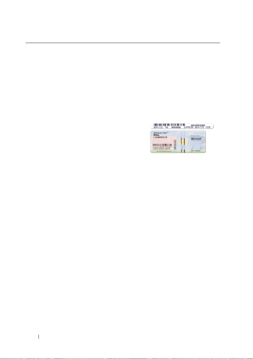
• Service Tag and Express Service Code
• Microsoft Windows License Label
Service Tag and Microsoft® Windows®
License
These labels are located on your
computer.
• Use the Service Tag to identify your
computer when you use
support.dell.com
• Enter the Express Service Code to direct
your call when contacting support.
NOTE: As an increased security measure,
the newly designed Microsoft Windows
license label incorporates a missing portion
or "hole" to discourage removal of the label.
or contact support.
16 Finding Information

What Are You Looking For? Find It Here
• Solutions — Troubleshooting hints and
tips, articles from technicians, and
online courses, frequently asked
questions
Dell Support Website — support.dell.com
NOTE: Select your region or business
segment to view the appropriate support
site.
• Community — Online discussion with
other Dell customers
• Upgrades — Upgrade information for
components, such as memory, the hard
drive, and the operating system
• Customer Care — Contact information,
service call and order status, warranty,
and repair information
• Service and support — Service call
status and support history, service
contract, online discussions with
technical support
• Dell Technical Update Service —
Proactive e-mail notification of software
and hardware updates for your computer
• Reference — Computer documentation,
details on my computer configuration,
product specifications, and white papers
• Downloads — Certified drivers, patches,
and software updates
• Desktop System Software (DSS) — If
you reinstall the operating system for
your computer, you should also reinstall
the DSS utility. DSS provides critical
updates for your operating system and
support for processors, optical drives,
USB devices, and so on. DSS is
necessary for correct operation of your
Dell computer. The software
automatically detects your computer
and operating system and installs the
updates appropriate for your
To download Desktop System Software:
1
Go to
support.dell.com
region or business segment, and enter
your Service Tag.
2
Select
Go
.
3
Click your operating system and search
for the keyword
Software
NOTE: The support.dell.com user interface
may vary depending on your selections.
configuration.
, select your
Drivers & Downloads
Desktop System
.
and click
Finding Information 17
What Are You Looking For? Find It Here
• How to use Microsoft Windows Vista™
• How to work with programs and files
• How to personalize my desktop
Windows Help and Support
1
Click the Windows Vista Start button
, and then click
2
In
Search Help
that describes your problem, and then
press <Enter> or click the magnifying
glass.
3
Click the topic that describes your
problem.
4
Follow the instructions on the screen.
• How to reinstall my operating system
Operating System Disc
NOTE: The Operating System disc may be
optional and may not ship with your
computer.
The operating system is already installed
on your computer. To reinstall your
operating system, use the Operating
System disc (see "Reinstalling Windows
XP or Windows Vista" on page 137).
Help and Support
, type a word or phrase
.
18 Finding Information
After you reinstall your operating system,
use the Drivers and Utilities disc to
reinstall drivers for the devices that came
with your computer.
Your operating system product key label is
located on your computer.
NOTE: The color of your disc varies based
on the operating system you ordered.

What Are You Looking For? Find It Here
• How to use Linux
• E-mail discussions with users of Dell
Precision™ products and the Linux
operating system
• Additional information regarding Linux
and my Dell Precision computer
Dell Supported Linux Sites
• Linux.dell.com
• Lists.us.dell.com/mailman/listinfo/linuxprecision
Finding Information 19

20 Finding Information
About Your Computer
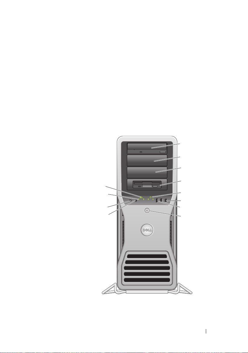
Front View of the Computer
2
1
2
3
9
10
11
12
About Your Computer 21
4
5
6
7
8

1-3 5.25-inch drive
bays
4 5.25-inch drive
bay with special
3.5-inch drive
panel plate
5 hard-drive
activity light
6 IEEE 1394
connector
7USB 2.0
connectors (2)
8 power button,
power light
9 network link light The network link light is on when a good connection exists
10 diagnostic lights
(4)
Can hold an optical drive, Media Card Reader, floppy drive,
or SATA hard drive in a 5.25-inch drive bay carrier.
The hard-drive carrier is only for use in the 5.25-inch drive
bays. The floppy drive/Media Card Reader and hard drive
carriers are not interchangeable.
Can hold an optical drive, Media Card Reader, floppy drive,
or SATA hard drive in a 5.25-inch drive bay carrier. The drivepanel plate shown here is only for use with a floppy drive or
Media Card Reader; it can be installed in front of any of the
four 5.25-inch drive bays. For more information, see "Drive
Panels" on page 246.
The hard-drive carrier is only for use in the 5.25-inch drive
bays. The floppy drive/Media Card Reader and hard drive
carriers are not interchangeable.
The hard drive light is on when the computer reads data from
or writes data to the hard drive. The light might also be on
when a device, such as your optical drive, is operating.
Use the IEEE 1394 connector for high-speed data devices
such as digital video cameras and external storage devices.
Use the front USB connectors for devices that you connect
occasionally, such as flash memory keys, cameras, or
bootable USB devices.
It is recommended that you use the back USB connectors for
devices that typically remain connected, such as printers
and keyboards.
Press the power button to turn on the computer. The light in
the center of this button indicates power state. See "Controls
and Lights" on page 32 for more information.
NOTICE: To avoid losing data, do not use the power
button to turn off the computer. Instead, perform an
operating system shutdown.
between a 10-Mbps, 100-Mbps, or 1000-Mbps (or 1-Gbps)
network and the computer.
Use these lights to help you troubleshoot a computer
problem based on the diagnostic code. For more information,
see "Diagnostic Lights" on page 105.
22 About Your Computer
11 microphone
connector
12 headphone
connector
Use the microphone connector to attach a personal
computer microphone for voice or musical input into a sound
or telephony program.
Use the headphone connector to attach headphones.
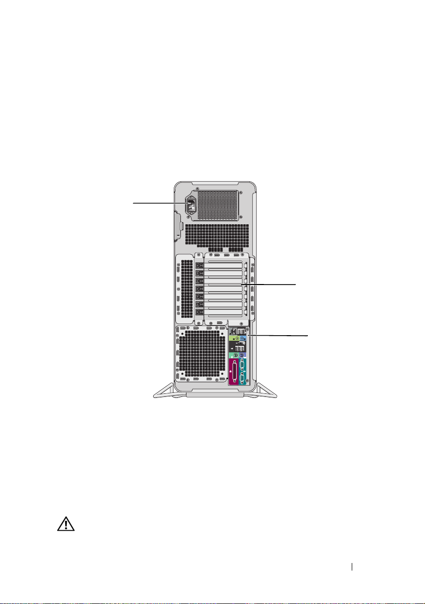
Back View of the Computer
1
2
3
1 power connector Insert the power cable.
2 card slots Slots 2-6 support full-length cards. This includes one PCI, two
PCI Express 2.0 x16, and two PCI-X slots.
Slots 1 and 7 support half-length cards. This includes one PCI
Express x8 (wired as x4) and one PCI-X slot.
3 back panel
connectors
CAUTION: Ensure that none of the system air vents are blocked. Blocking them
would cause serious thermal problems.
Plug USB, audio, and other devices into the appropriate
connector (see "Back Panel Connectors" on page 24 for more
information.
About Your Computer 23
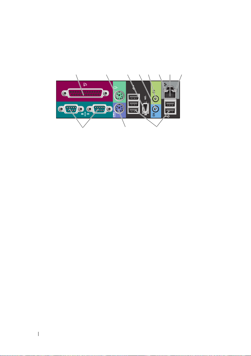
Back Panel Connectors
1 2 345678
91011
1 parallel connector Connect a parallel device, such as a printer, to the parallel
connector. If you have a USB printer, plug it into a USB
connector.
NOTE: The integrated parallel connector is automatically
disabled if the computer detects an installed card containing a
parallel connector configured to the same address. For more
information, see "System Setup Options" on page 75.
2 mouse connector Plug a standard PS/2 mouse into the green mouse connector.
Turn off the computer and any attached devices before you
connect a mouse to the computer. If you have a USB mouse,
plug it into a USB connector.
3 IEEE 1394
connector
4 line-in connector Use the blue line-in connector to attach a playback device
5 line-out connector Use the green line-out connector to attach most speakers with
Use the IEEE 1394 connector for high-speed data devices such
as digital video cameras and external storage devices.
such as an MP3 player, CD drive, or VCR. On computers with a
sound card, use the connector on the card.
integrated amplifiers.
On computers with a sound card, use the connector on the
card.
24 About Your Computer

6 link integrity light Green — A good connection exists between a 10-Mbps
network and the computer
Orange — A good connection exists between a 100-Mbps
network and the computer
Yellow — A good connection exists between a 1000-Mbps (or
1-Gbps) network and the computer
Off — The computer is not detecting a physical connection to
the network
7 network adapter
connector
8 network activity
light
9 serial connectors
(2)
10 keyboard
connector
11 USB 2.0
connectors (5)
To attach your computer to a network or broadband device,
connect one end of a network cable to either a network jack or
your network or broadband device. Connect the other end of
the network cable to the network adapter connector on your
computer. A click indicates that the network cable has been
securely attached.
Do not plug a telephone cable into the network connector.
On computers with an additional network connector card, use
the connectors on the card and on the back of the computer
when setting up multiple network connections (such as a
separate intra- and extranet).
It is recommended that you use Category 5 wiring and
connectors for your network. If you must use Category 3
wiring, force the network speed to 10 Mbps to ensure reliable
operation.
Flashes a yellow light when the computer is transmitting or
receiving network data. A high volume of network traffic may
make this light appear to be in a steady "on" state.
Connect a serial device, such as a handheld device, to the
serial port. If necessary, the address for this port can be
modified through system setup (see "System Setup" on
page 75).
If you have a standard PS/2 keyboard, plug it into the purple
keyboard connector. If you have a USB keyboard, plug it into a
USB connector.
It is recommended that you use the front USB connectors for
devices that you connect occasionally, such as flash memory
keys, cameras, or bootable USB devices.
Use the back USB connectors for devices that typically remain
connected, such as printers and keyboards.
About Your Computer 25
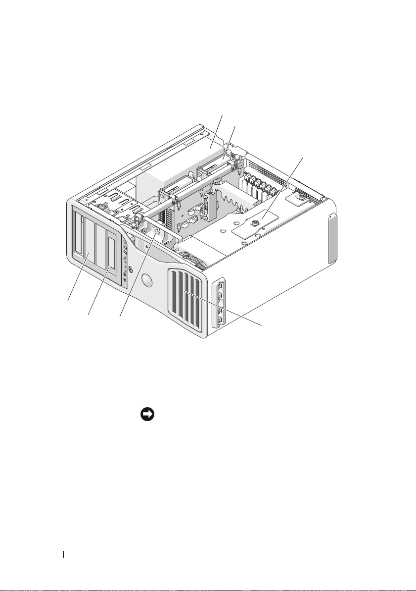
Inside View
4
5
1
2
3
6
7
1 power supply
2 hard drive bay
3 memory shroud
4 5.25-inch drive bay
5 5.25-inch drive bay with 3.5-inch drive panel
plate
26 About Your Computer
NOTICE: The memory shroud holds
the (optional) memory riser cards in
place; its thumbscrews must be
sufficiently tight in order to secure the
risers and to avoid damage.
6 card fan
7front fan
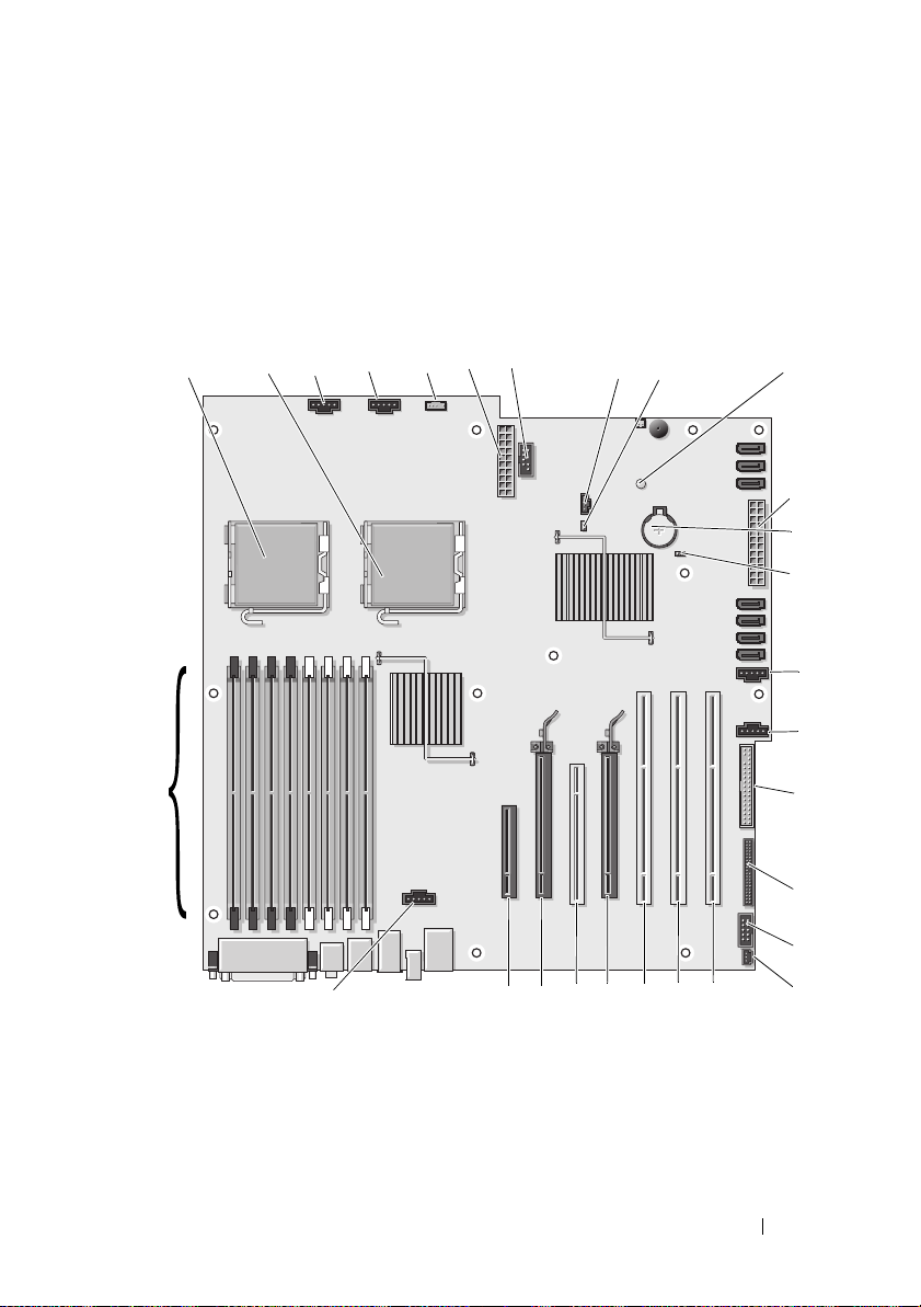
System Board Components
1
30
367 98 10
2
29
54
11
}
12
13
14
15
}
16
17
18
19
20
22232425262728
21
About Your Computer 27

1 primary processor connector
(CPU_0)
2 secondary processor connector
(CPU_1)
3 front fan connector (FAN_FRONT) 18 floppy drive (DSKT)
4 card cage fan (FAN_CCAG) 19 front panel connector (FRONTPANEL)
5 internal speaker connector
(INT_SPKR)
6 power connector (POWER2) 21 chassis intrusion header (INTRUDER)
7 USB (INT_USB) 22 PCI-X card slot (SLOT7_PCIX)
8 auxiliary hard drive LED (AUX_LED) 23 PCI-X card slot (SLOT6_PCIX)
9 password jumper (PSWD) 24 PCI-X card slot (SLOT5_PCIX)
10 auxiliary power LED (AUX_PWR) 25 PCI Express 2.0 x16 card slot
11 SATA connectors for hard drives or
optical drives (SATA_0, SATA_1,
SATA_2)
12 main power connector (POWER1) 27 PCI Express 2.0 x16 card slot
13 battery socket (BATTERY) 28 PCI Express x8 card slot, wired as x4
14 RTC reset jumper (RTCRST) 29 memory fan connector (FAN_MEM)
16 hard drive fan (FAN_HDD)
17 secondary hard drive fan (FAN_HDD2)
20 front panel 1394 connector (FP1394)
(SLOT4_PCI e2x16)
26 PCI slot (SLOT3_PCI)
(SLOT2_PCI e2x16)
(SLOT1_PCIE)
15 hard drive connectors for SAS or
SATA hard drives (HDD_0, HDD_1,
HDD_2), HDD_3
Cable Colors
Device Color
SATA hard drive blue cable
Floppy drive black pull tab
Optical drive orange cable
front panel yellow pull tab
28 About Your Computer
30 memory module connectors
DIMM_1-8)

Specifications
NOTE: Offerings may vary by region. For more information regarding the
configuration of your computer, click Start→ Help and Support and select the
option to view information about your computer.
Processor
®
Processor type Dual-Core Intel
series
Quad-Core Intel® Xeon® Processor 5400
series
Internal cache Dual-Core Intel® Xeon® Processor 5200
series - 6 MB
Quad-Core Intel
series - 12 MB
External bus frequency 1333- or 1600-MHz data rate
Memory
Memory module connectors
Memory module capacities 512-MB or 1-, 2-, or 4-GB ECC
Memory type 667- or 800-MHz fully-buffered DDR2
Minimum memory 1 GB
Maximum memory 64 GB with optional memory riser cards
BIOS address F0000h
8 (16 with optional memory riser)
SDRAM fully-buffered DIMMs (FBDs)
NOTICE: Full-length heat spreaders
(FLHS) are required for all memory.
32 GB standard
Xeon® Processor 5200
®
Xeon® Processor 5400
System Information
System chipset
Data bus width 64 bits
DRAM bus width Quad-channel fully-buffered DIMM
Processor address bus width 38 Bits
Intel 5400
About Your Computer 29

System Information
Flash EPROM 8 Mbit
Graphics bus Two PCI Express 2.0 x16 slots
Expansion
Card support Center five connector slots support full-
Cards supported PCI 2.3
PCI
connector
connector size
connector data width (maximum)
bus transfer rate 133 MB/s
PCI-X
connectors
connector size
connector data width (maximum)
bus transfer rate
PCI Express x8 (wired as x4)
connectors
connector size
connector data width (maximum)
bus transfer rate
PCI Express 2.0 x16
(continued)
length cards.
The connector slots on either side (one x8
PCI Express slot (wired as x4) and one PCIX card) support half-length cards.
PCI Express 1.0A
PCI Express 2.0 x16
PCI-X 2.0A
one
120 pins
32 bits
three
188 pins
64 bits
800 MB/s
one x8 (support x8, x4, and x1 modes/cards;
maximum x4 link width)
98 pins
4 PCI Express lanes
2.5 GB/s/lane/direction (raw bandwidth)
30 About Your Computer
 Loading...