

Dell PowerEdge C6220 User Manual

Dell PowerEdge
C8220/C8220X/C8000/C6220
Using the Baseboard
Management Controller
FILE LOCATION: D:\Projects\User Guide\Server\Dell\OOB\HOM\C8220-C8220X BMC\BMC\C8220-
C8220X_BMC_HOM_tp.fm
Template Last Updated -03/06/2010

FILE LOCATION: D:\Projects\User Guide\Server\Dell\OOB\HOM\C8220-C8220X
BMC\BMC\C8220-C8220X_BMC_HOM_tp.fm
NOTE: A NOTE indicates important information that helps you make better use of
your computer.
CAUTION: A CAUTION indicates potential damage to hardware or loss of data if
instructions are not followed.
WARNING: A WARNING indicates a potential for property damage, personal
injury, or death.
____________________
Information in this publication is subject to change without notice.
© 2013 Dell Inc. All rights reserved.
Reproduction of these materials in any manner whatsoever without the written permission of Dell Inc.
is strictly forbidden.
Trademarks used in this text: Dell™, the DELL logo, and PowerEdge™ are trademarks of Dell Inc.
Microsoft
either trademarks or registered trademarks of Microsoft Corporation in the United States and/or other
countries. Red Hat
the United States and/or other countries. Oracle and Java are registered trademarks of Oracle and/or
its affiliates. Intel is a registered trademark of Intel Corporation in the U.S. and other countries.
Other trademarks and trade names may be used in this publication to refer to either the entities claiming
the marks and names or their products. Dell Inc. disclaims any proprietary interest in trademarks and
trade names other than its own.
2013 - 06 Rev. A04
®
, Windows®, Windows Server®, MS-DOS®, Windows Vista®, and Internet Explorer® are
®
and Red Hat® Enterprise Linux® are registered trademarks of Red Hat, Inc. in

FILE LOCATION: D:\Projects\User Guide\Server\Dell\OOB\HOM\C8220-C8220X
BMC\BMC\C8220-C8220X_BMC_HOM_bk0TOC.fm
Contents
Intelligent Platform Management Interface . 5
Baseboard Management Controller. . . . . . . . . . . . 5
Supported Platform . . . . . . . . . . . . . . . . . . . . 5
BMC Key Features and Functions
Using the Web User Interface
. . . . . . . . . . . . . 5
. . . . . . . . . . . . . . . 6
Logging in to the Web User Interface . . . . . . . . . . . 7
Remote Management Controller
Properties
Chassis
. . . . . . . . . . . . . . . . . . . . . . 10
. . . . . . . . . . . . . . . . . . . . . . . 11
. . . . . . . . . . . . . 9
Configuration . . . . . . . . . . . . . . . . . . . . 12
Sessions
Update
. . . . . . . . . . . . . . . . . . . . . . 20
. . . . . . . . . . . . . . . . . . . . . . . 21
Utilities . . . . . . . . . . . . . . . . . . . . . . . 23
Server Information . . . . . . . . . . . . . . . . . . . . 24
Sensor Monitor
. . . . . . . . . . . . . . . . . . . 24
Power . . . . . . . . . . . . . . . . . . . . . . . . 35
System Event Log. . . . . . . . . . . . . . . . . . . . . 36
Event Management
. . . . . . . . . . . . . . . . . 37
Trap Settings . . . . . . . . . . . . . . . . . . . . 39
Email Settings
Serial Over LAN
vKVM & vMedia
. . . . . . . . . . . . . . . . . . . . 40
. . . . . . . . . . . . . . . . . . . . . 43
. . . . . . . . . . . . . . . . . . 44
Contents
3

FILE LOCATION: D:\Projects\User Guide\Server\Dell\OOB\HOM\C8220-C8220X
BMC\BMC\C8220-C8220X_BMC_HOM_bk0TOC.fm
Using the Video Viewer . . . . . . . . . . . . . . . . . 48
Video Viewer Menu
. . . . . . . . . . . . . . . . . 49
IPMI 1.5/2.0 Commands Support List
. . . . . . . . . . . 52
OEM Commands Support List . . . . . . . . . . . . . . 62
Extended Configuration Commands
Threshold Settings and Converting Formulas
. . . . . . . . 62
. . . . . . 77
4 Contents

Intelligent Platform Management Interface
The Intelligent Platform Management Interface (IPMI) defines a set of
standardized, message-based interfaces that monitor system hardware health
(fan speed, temperature, voltage, power supply, and so on.), control system
components, and store data about important system events in a system event
log (SEL) for later examination. IPMI provides the foundation for remote
platform management.
NOTE: To learn more about IPMI, see intel.com/design/servers/ipmi/.
Baseboard Management Controller
The key component in the IPMI system is the baseboard management
controller (BMC), a microcontroller located on the server’s system board.
BMC is the “intelligence” within the IPMI architecture, responsible for
monitoring and controlling the server’s manageable devices.
BMC is connected to the various sensors through the Intelligent Platform
Management Bus (IPMB), a subset of the I2C bus. System software
communicates with BMC using a keyboard controller style (KCS) interface.
Supported Platform
PowerEdge C8220 and C8220X
BMC Key Features and Functions
The features supported by BMC are as follows:
• Support for IPMI v1.5 and v2.0
• Out-of-band monitoring and control for server management over LAN
• Dedicated NIC for remote management via network
• FRU information report, which includes system board part number,
product name, and manufacturer.
• Health status/hardware monitoring report
• View and clear events log
• Event notification by lighting chassis LED indicator and Platform Event
Tra p ( PE T)
Template Last Updated - 2/7/2007 5

FILE LOCATION: D:\Projects\User Guide\Server\Dell\OOB\HOM\C8220-C8220X
BMC\BMC\C8220-C8220X_BMC_HOM_section1.fm
• Platform Event Filtering (PEF) to take selected action for selected events
• Chassis management, which includes power control, status report, front
panel buttons, and LEDs control
• PowerEdge C8220X compute sled management, which includes Xeon Phi
5110P/7110P MIC card and NPDB board
NOTE: Make sure all cables are properly attached to the 5110/7110P MIC card and
NPDB board. See the PowerEdge C8220X Hardware Owner’s Manual for more
information. This document is available at dell.com/support/manuals.
• Watchdog and auto server re-start and recovery
• Multi-session user and alert destination for LAN channel
Using the Web User Interface
The BMC firmware features an embedded web server, enabling users to
connect to the BMC using an Internet browser (Windows Internet Explorer)
without needing to install KVM and virtual storage software on a remote
console.
Web-based GUI is supported on the following browsers:
• Microsoft Windows:
– Internet Explorer 6, 7, 8, 9
– Mozilla Firefox 7, 8, 9
– Google Chrome 3.0 (optional)
•Linux:
– Mozilla Firefox 7, 8, 9
•Mac OS:
– Safari V5.X
6

FILE LOCATION: D:\Projects\User Guide\Server\Dell\OOB\HOM\C8220-C8220X
BMC\BMC\C8220-C8220X_BMC_HOM_section1.fm
Logging in to the Web User Interface
Users must enter the PowerEdge C8220 and C8220X embedded server IP
address or URL (default DHCP\static IP address) into the address bar of the
web browser.
When connecting to the PowerEdge C8220 and C8220X using a web browser,
Secure Sockets Layer (SSL) is automatically activated and the display user
login form is displayed prompting for the username and password. This
authentication with SSL protection prevents unauthorized intruders from
gaining access to the PowerEdge C8220 and C8220X web server. If
authentication is passed, you can manage the server by privilege.
A security certificate warning displays, choose Continue to this website (not
recommended) to continue.
The user authentication web page is displayed. Enter the default user name
and password, and click OK.
7
FILE LOCATION: D:\Projects\User Guide\Server\Dell\OOB\HOM\C8220-C8220X
Table 1-1. Default User Name and Password
Field Default
User Name root
Password root
NOTE: The default username and password are in lowercase characters. It is
advised to change the root password once you have logged in.
BMC\BMC\C8220-C8220X_BMC_HOM_section1.fm
Click the Help button on the top right corner for assistance. Click Logout to
exit.
The Remote Management Controller’s web UI is divided into two areas. On
the left is the multi-level navigation menu bar, which is divided into four
categories and each category is subdivided into several submenus. On the
right is the information pane, which displays a list of information, commands
or configuration options that are associated with the category selected from
the navigation menu bar.
8

FILE LOCATION: D:\Projects\User Guide\Server\Dell\OOB\HOM\C8220-C8220X
BMC\BMC\C8220-C8220X_BMC_HOM_section1.fm
Remote Management Controller
The Remote Management Controller menu provides general information
about the server including the BMC firmware and network information.
Administrators and operators can use this menu to check the sled server
health and access all network configuration options. It also provides options
for managing security, user access, session status, updating the BMC
firmware, and performing remote system shutdown or reboot.
The remote management controller menu provides access to the following
configuration options:
• Properties
•Chassis
• Configuration
• Sessions
•Update
• Utilities
9

FILE LOCATION: D:\Projects\User Guide\Server\Dell\OOB\HOM\C8220-C8220X
BMC\BMC\C8220-C8220X_BMC_HOM_section1.fm
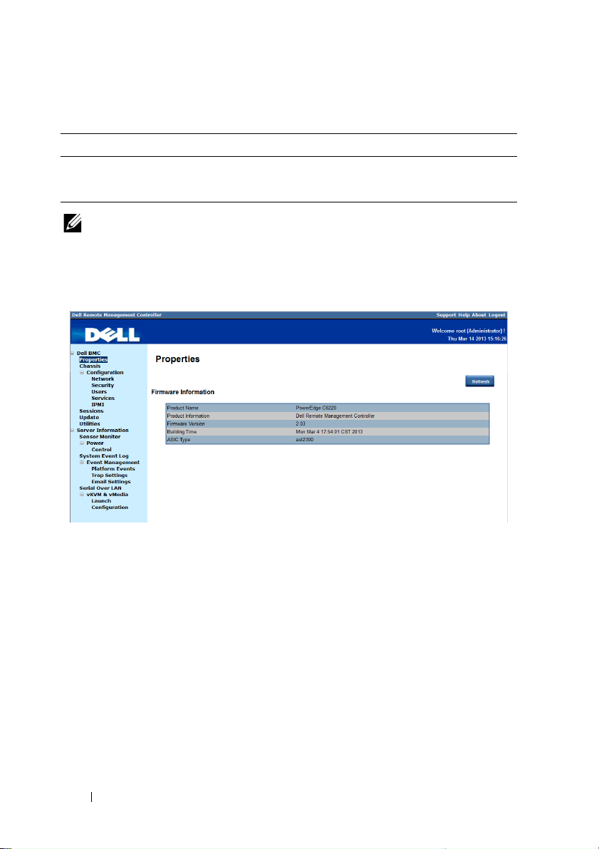
Properties
The Properties option enables you to view the remote sled server BMC
firmware information.
Table 1-2. Firmware Summary
Item Description
Product Name Sled server system board model name
Product Information Remote Management Controller firmware
Firmware Version Remote Management Controller firmware version
Building Time Date the firmware was last flashed in the following
format:
MM DD YYYY HH: MM: SS
ASIC Type Application-specific integrated circuit (ASIC) type
Refresh Button Use this button to refresh the firmware information
10
FILE LOCATION: D:\Projects\User Guide\Server\Dell\OOB\HOM\C8220-C8220X
BMC\BMC\C8220-C8220X_BMC_HOM_section1.fm
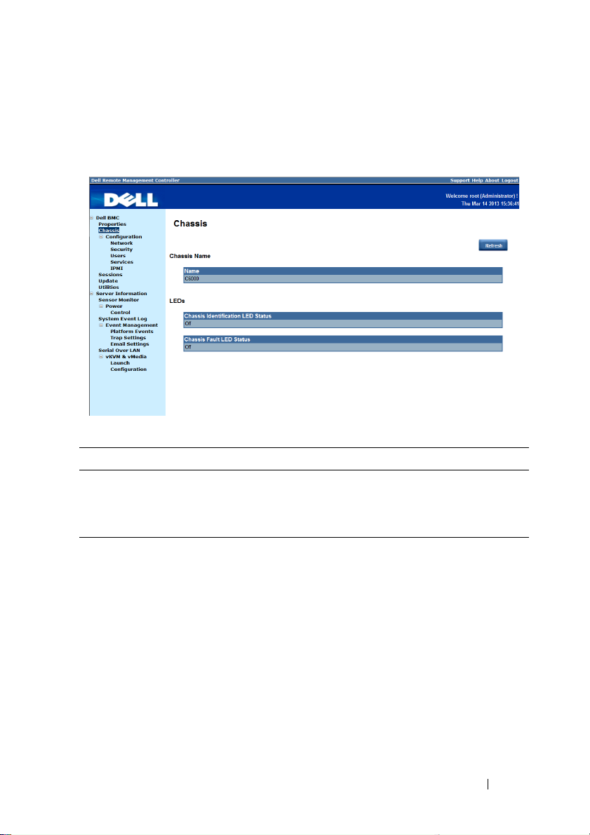
Chassis
The Chassis option enables you to view a summary chassis information
including LEDs and power supply status.
Table 1-3. Chassis Summary
Item Description
Chassis Name Server chassis product model name
LEDs Server chassis identification and fault LED status
Refresh Button Use this button to refresh the chassis information
11

FILE LOCATION: D:\Projects\User Guide\Server\Dell\OOB\HOM\C8220-C8220X
BMC\BMC\C8220-C8220X_BMC_HOM_section1.fm
Configuration
The Configuration option enables you to view and set values for various
system functions.
Click on the Configuration option to expand the submenu items.
•Network
•Security
•Users
•Services
•IPMI
Network
Select the Network submenu to view and configure the network setting
parameters.
NOTE: To change any network setting parameters, you must have permission to
configure the BMC.
12

FILE LOCATION: D:\Projects\User Guide\Server\Dell\OOB\HOM\C8220-C8220X
BMC\BMC\C8220-C8220X_BMC_HOM_section1.fm
Table 1-4. Network
Item Description
General Settings
Mode Select a network connectivity mode.
Host Name Type the name of the BMC host server in this field.
DNS Domain Name Type the domain name of the DNS server in this field.
Network Interface Configuration
Name Column Indicates the network interface name.
iF Enabled Column Indicates the operational status of the NIC.
IPv4 Enabled Column Indicates the operational status of the Internet Protocol
version 4 (IPv4).
IPv4 Address Column Indicates the IPv4 IP address.
IPv6 Enabled Column Indicates the operational status of the IPv6 protocol.
IPv6 Address Column Indicates the IPv6 IP address.
Apply Changes Button
Refresh Button
Use this button to apply the changes.
Use this button to refresh the network information.
13

FILE LOCATION: D:\Projects\User Guide\Server\Dell\OOB\HOM\C8220-C8220X
BMC\BMC\C8220-C8220X_BMC_HOM_section1.fm
Security
Select the Security submenu to view server certificate information. Secure
server certificates ensure the identity of a remote system and ensure that
information exchanged with the remote system cannot be viewed or changed
by others. Users with administrator or operator privileges can create a
Certificate Signing Request (CSR) and upload the file to a certifying
authority.
Table 1-5. Security
Options Description
Serial Number Server certificate serial number
Subject Information:
Country Code (CC) Name of the country where the entity applying for the
certification is located
State (S) State or province where the entity applying for the
certification is located
Locality (L) City or location of the entity being certified
Organization (O) Legal name of the company or institution
Organizational Unit (OU) Name associated with the organizational unit
Common Name (CN) DNS host name
14

FILE LOCATION: D:\Projects\User Guide\Server\Dell\OOB\HOM\C8220-C8220X
BMC\BMC\C8220-C8220X_BMC_HOM_section1.fm
Table 1-5. Security
Options Description
Issuer Information:
Country Code (CC) Country that issued the certificate
State (S) State that issued the certificate
Locality (L) City or location that issued the certificate
Organization (O) Name of the institution that issued the certificate
Organizational Unit (OU) Unit that issued the certificate
Common Name (CN) Certification authority
Valid From Server certificate effective date
Valid Until Server certificate expiration date
Generate Certificate
Button
Use this button to create a Certificate Signing Request
(CSR)
Upload Certificate Button Use this button to upload the CSR file to a certifying
authority
15
FILE LOCATION: D:\Projects\User Guide\Server\Dell\OOB\HOM\C8220-C8220X
BMC\BMC\C8220-C8220X_BMC_HOM_section1.fm
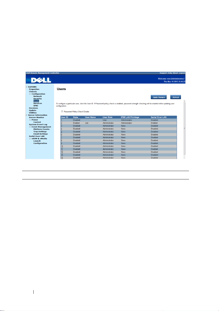
Users
Select the Users submenu to view the list of users authorized to access the
system. Administrators can grant any user permission privileges by clicking a
user ID number.
Table 1-6. Users
Item Description
Password Policy Check
Enable Checkbox
Enables you to improve the security of your passwords
by enforcing strong password security policies.
If enabled, BMC will perform a password check each
time the user configuration is updated. The user
password must have the following requirements:
• Cannot contain the user’s account name or full name.
• Must have a minimum of 8 and a maximum of 14
alphanumeric characters.
• Can contain numbers (0-9), upper and lower case
letters (A-Z, a-z), special characters (for example, !, $,
#, %).
• Can contain a catch-all category of any Unicode
character that does not fall under the previous three
categories. This category can be regionally specific.
• Cannot contain or be similar to the last 5 passwords.
16

FILE LOCATION: D:\Projects\User Guide\Server\Dell\OOB\HOM\C8220-C8220X
BMC\BMC\C8220-C8220X_BMC_HOM_section1.fm
Table 1-6. Users
Item Description
User ID Column Displays a list of users who can access this BMC
If a privilege is assigned to a user, the user ID appears as
a hyperlink.
State Column Shows the status of each user
User Name Column Shows the login name of the user
User Role Column Shows user defined roles
IPMI LAN Privilege
Displays the IPMI LAN privilege level
Column
IPMI Serial Privilege
Displays the IPMI serial privilege level
Column
Serial Over LAN Column Indicates whether permission for configuring the serial
over LAN connection is enabled or disabled
SOL provides serial access over the NIC interface. The
server’s integrated BMC redirects data information from
the serial port (UART), and packs the data and transfers
the UART data to the NIC interface.
Apply Changes Button Use this button to apply the changes
Refresh Button Use this button to refresh the user list
17
FILE LOCATION: D:\Projects\User Guide\Server\Dell\OOB\HOM\C8220-C8220X
BMC\BMC\C8220-C8220X_BMC_HOM_section1.fm
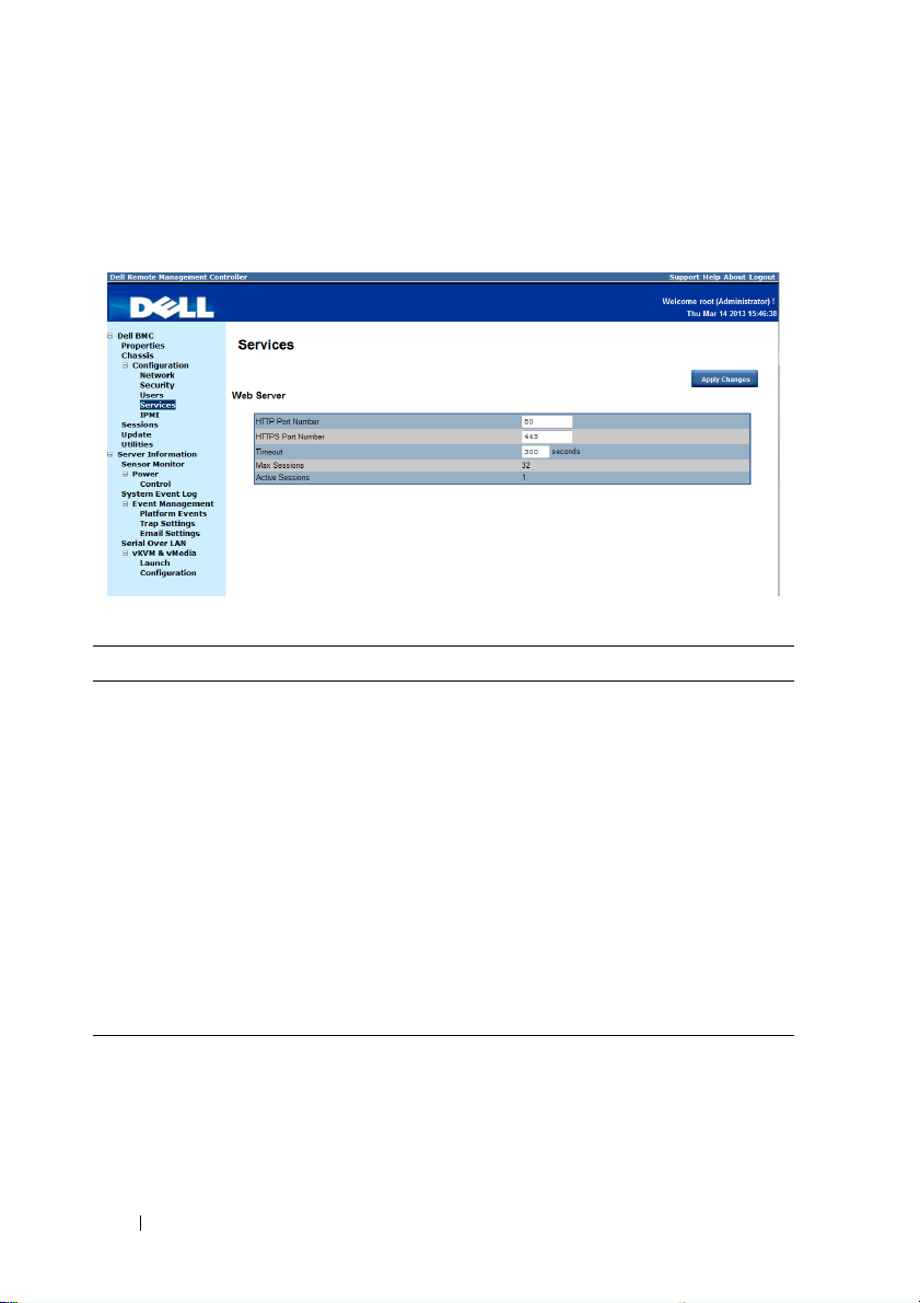
Services
Select the Services submenu to view the communication service parameters.
Users with administrator or operator privileges can set up this service.
Table 1-7. Services
Item Description
HTTP Port Number Port to use for HTTP-based communication. The
default HTTP port number is 80.
HTTPS Port Number Port to use for HTTPS-based communication. The
default HTTPS port number is 443.
Timeout Specify the timeout value. The timeout value can range
from 60 to 10800 seconds.
Max Sessions Indicates the number of simultaneous sessions allowed
for the system.
Active Sessions Indicates the number of sessions currently running on
the system.
Apply Changes Button Use this button to apply the changes and restart the web
server.
18
FILE LOCATION: D:\Projects\User Guide\Server\Dell\OOB\HOM\C8220-C8220X
BMC\BMC\C8220-C8220X_BMC_HOM_section1.fm
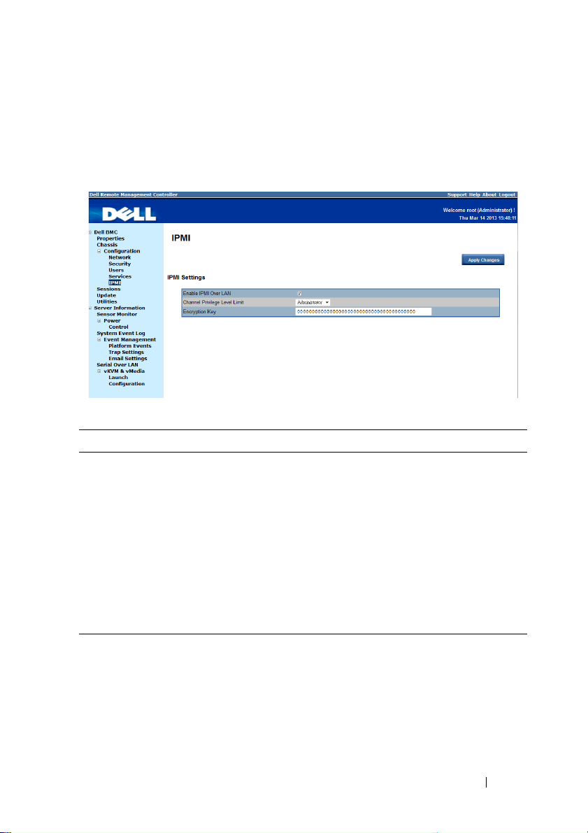
IPMI
Select the IPMI submenu to view the IPMI-based communication service
parameters. Users with administrator or operator privileges can configure the
IPMI settings.
Table 1-8. IPMI
Item Description
IPMI Settings
Enable IPMI Over LAN
Channel Privilege Level
Limit
Encryption Key
Enables or disables IPMI over LAN access.
Select a user privilege level for IPMI over LAN access.
Type the IPMI LAN channel encryption key.
NOTE: The encryption key must consist of an even
number of hexadecimal characters with a maximum of 20
ASCII hex pairs with no spaces between the pairs.
Apply Changes Button
Use this button to apply the changes.
19

FILE LOCATION: D:\Projects\User Guide\Server\Dell\OOB\HOM\C8220-C8220X
BMC\BMC\C8220-C8220X_BMC_HOM_section1.fm
Sessions
The Sessions option enables you to view sessions currently running on the
system.
Table 1-9. Sessions
Item Description
Session ID Column Shows the number of active sessions or session ID
numbers.
User Name Column Shows the login name of the user.
IP Address Column Shows the IP address of the user.
Session Type Column Indicates media session type — Virtual KVM, Virtual
Media, or GUI.
Kill This column includes a Trash icon that enables users
with administrator or operator privilege to end an
associated session.
Refresh Button Use this button to refresh the session information.
20

FILE LOCATION: D:\Projects\User Guide\Server\Dell\OOB\HOM\C8220-C8220X
BMC\BMC\C8220-C8220X_BMC_HOM_section1.fm
Update
The Update option enables users with administrator or operator privileges to
update the sled server’s BMC firmware. The following data is included in the
BMC firmware package:
• Compiled BMC firmware code and data
• Web-based user interface, JPEG, and other user interface data files
• Default configuration files
NOTE: The firmware update retains the current BMC settings.
Table 1-10. Update
Item Description
Firmware Type Select the firmware type (BMC/BIOS/FC) that you
want to upgrade.
NOTE: If a fan controller board (FCB) firmware update
type is selected, the sled(s) in the server chassis that are
not performing the update request or action will consider
the FCB firmware offline after 10 seconds.
File Path Enter the complete path and file name for the firmware
file.
21

FILE LOCATION: D:\Projects\User Guide\Server\Dell\OOB\HOM\C8220-C8220X
Table 1-10. Update
Item Description
Browse Button Use this button to navigate to the firmware file saved
Update Type Select a firmware update type.
BMC\BMC\C8220-C8220X_BMC_HOM_section1.fm
onto a media.
• Normal (default): Updates the firmware only when the
BMC validates the target board, target product, and
version number.
• Forced: This forces the BMC to update the image
without first validating the target board, target product
and version number.
CAUTION: Do not attempt a forced firmware upgrade
without assistance from Dell Technical Support.
Upload Button Use this button to initialize the update process.
Updating the BMC Firmware
CAUTION: Before beginning the firmware update, download the latest firmware
version and save it on your local system. During the process of a firmware update,
the AC power of the managed system should not be unplugged and the Web GUI
should not be closed.
NOTE: You will not be able to perform any task during the firmware upgrade
process. Wait for the upgrade to be completed before attempting any task.
1
Click the
2
Click
Update
Browse
menu to access the Firmware Update page.
to locate the firmware file. Or, enter the path on your system
where the firmware image file resides. For example:
C:\Updates\V1.0\<image_name>
3
Select firmware update type. If a BMC firmware update type is selected,
after the upload process is started, any attempt to refresh, logout or
navigate away from the update page will restart the remote system.
When you choose to force a firmware update, BMC will update the image
without first validating the target board, target product and version
number.
4
Click
Upload
NOTE: The upload process terminates all other sessions including KVM.
to initialize the update process.
22

FILE LOCATION: D:\Projects\User Guide\Server\Dell\OOB\HOM\C8220-C8220X
5
Click
BMC\BMC\C8220-C8220X_BMC_HOM_section1.fm
Updat
e. When the update is completed, the remote system will
reboots automatically.
NOTE: When the firmware update is in process, the system will not be available to
other users.
Utilities
The Utilities option enables users with administrator and operator privileges
to remotely reboot or reset the BMC firmware.
Table 1-11. Utilities
Item Description
Reboot Button Use this button to remotely reboot this BMC firmware.
BMC initialization time is up to 120 seconds. BMC
cannot accept any command request before
initialization has been performed.
Factory Default Button Use this button to reset the BMC configuration values
back to default values.
CAUTION: This will reset all BMC settings back to
default setting.
23

FILE LOCATION: D:\Projects\User Guide\Server\Dell\OOB\HOM\C8220-C8220X
BMC\BMC\C8220-C8220X_BMC_HOM_section1.fm
Server Information
The Server Information menu enables users with administrator and operator
privileges to remotely perform a power control operation on the server.
The Server Information menu provides access to the following configuration
options.
• Sensor Monitor
•Power
Sensor Monitor
The Sensor Monitor option enables users with administrator and operator
privileges to remotely monitor the server’s voltage, power supplies, batteries,
fan sensors and temperature sensors.
If the server power is off, the following message appears on the screen:
The System is powered off. Unable to retrieve the sensor
information.
NOTE: Remote Management Controller does not store configuration settings in the
Sensor Monitor page.
24
 Loading...