

Dell PowerEdge C5125 User Manual

Dell PowerEdge C5125
Hardware Owner’s
Manual
Regulatory Model: B04S

Notes, Cautions, and Warnings
NOTE: A NOTE indicates important information that helps you make better use of
your computer.
CAUTION: A CAUTION indicates potential damage to hardware or loss of data if
instructions are not followed.
WARNING: A WARNING indicates a potential for property damage, personal
injury, or death.
Information in this publication is subject to change without notice.
© 2011 Dell Inc.Allrightsreserved.
Reproduction of these materials in any manner whatsoever without the written permission of Dell Inc.
is strictly forbidden.
®
Trademarks used in this text: AMD
Advanced Micro Devices, Inc. Dell™, the DELL logo, and PowerEdge™ are trademarks of Dell Inc.
Microsoft
in the United States and/or other countries.
Other trademarks and trade names may be used in this publication to refer to either the entities claiming
the marks and names or their products. Dell Inc. disclaims any proprietary interest in trademarks and
trade names other than its own.
®
and Windows® are either trademarks or registered trademarks of Microsoft Corporation
, AMD Phenom™, and AMD Athlon™ are trademarks of
Regulatory Model: B04S
2011-05 Rev. A00

Contents
1 About the System . . . . . . . . . . . . . . . . . . . . . . . . . 7
Front-Panel Features and Indicators . . . . . . . . . . . . . . . . . . 8
2 Using the System Setup Program . . . . . . . . . . . . . 11
Setup Menu . . . . . . . . . . . . . . . . . . . . . . . . . . . . . . . 11
BIOS Setup Options at Boot
Console Redirection
Configuring Special Keys
The Legend Bar
General Help
Access Level
Main Menu
Advanced Menu
Boot Menu
Server Menu
Security Menu
Exit Menu
. . . . . . . . . . . . . . . . . . . . . . . . . . . . . 14
. . . . . . . . . . . . . . . . . . . . . . . . . . . . . . 14
. . . . . . . . . . . . . . . . . . . . . . . . . . . . . . 15
. . . . . . . . . . . . . . . . . . . . . . . . . . . . . . . 16
. . . . . . . . . . . . . . . . . . . . . . . . . . . . . 19
. . . . . . . . . . . . . . . . . . . . . . . . . . . . . . . . 28
. . . . . . . . . . . . . . . . . . . . . . . . . . . . . . . 33
. . . . . . . . . . . . . . . . . . . . . . . . . . . . . . 39
. . . . . . . . . . . . . . . . . . . . . . . . . . . . . . . . 40
Loading BIOS Defaults
. . . . . . . . . . . . . . . . . . . . . . . 12
. . . . . . . . . . . . . . . . . . . . . . . . . . . 12
. . . . . . . . . . . . . . . . . . . . . . . . 12
. . . . . . . . . . . . . . . . . . . . . . . . . 42
POST Error Messages and Handling
IRQ Assignment Conflicts
. . . . . . . . . . . . . . . . . . . . . . . . 45
. . . . . . . . . . . . . . . . . . 42
3

3 Installing System Components . . . . . . . . . . . . . . . 47
Recommended Tools . . . . . . . . . . . . . . . . . . . . . . . . . 47
Inside the System
Sled Configuration
Removing a Sled
Installing a Sled
Removing Memory Modules
Installing a Memory Module
Removing 2.5" Hard-Drives
Installing 2.5" Hard-Drives
Removing 3.5" Hard-Drives
Installing 3.5" Hard-Drives
Removing a Heat Sink
Installing a Heat Sink
Removing a Processor
Installing a Processor
. . . . . . . . . . . . . . . . . . . . . . . . . . . 48
. . . . . . . . . . . . . . . . . . . . . . . . . . . 49
. . . . . . . . . . . . . . . . . . . . . . . . . . . . 50
. . . . . . . . . . . . . . . . . . . . . . . . . . . . 50
. . . . . . . . . . . . . . . . . . . . . 51
. . . . . . . . . . . . . . . . . . . . . 52
. . . . . . . . . . . . . . . . . . . . . . 56
. . . . . . . . . . . . . . . . . . . . . . 57
. . . . . . . . . . . . . . . . . . . . . . 58
. . . . . . . . . . . . . . . . . . . . . . 60
. . . . . . . . . . . . . . . . . . . . . . . . . 60
. . . . . . . . . . . . . . . . . . . . . . . . . 61
. . . . . . . . . . . . . . . . . . . . . . . . . 62
. . . . . . . . . . . . . . . . . . . . . . . . . 63
Removing the 2.5" Hard-Drive Board
Installing the 2.5" Hard-Drive Board
. . . . . . . . . . . . . . . . . 63
. . . . . . . . . . . . . . . . . 64
Removing the 3.5" Hard-Drive Board
Installing the 3.5" Hard-Drive Board
Removing the System Board
Installing the System Board
Removing a Power Supply Unit
Installing a Power Supply Unit
. . . . . . . . . . . . . . . . . 65
. . . . . . . . . . . . . . . . . 66
. . . . . . . . . . . . . . . . . . . . . 67
. . . . . . . . . . . . . . . . . . . . . . 67
. . . . . . . . . . . . . . . . . . . . 68
. . . . . . . . . . . . . . . . . . . . 69
4

Removing the Chassis Cover . . . . . . . . . . . . . . . . . . . . . . 70
Installing the Chassis Cover
Removing the Fan Cage
Installing the Fan Cage
Removing a Backplane
Installing a Backplane
Removing a Power Distribution Board
Installing a PDB Board
Removing the RTC Battery
Installing the RTC Battery
. . . . . . . . . . . . . . . . . . . . . . 71
. . . . . . . . . . . . . . . . . . . . . . . . . 72
. . . . . . . . . . . . . . . . . . . . . . . . . 74
. . . . . . . . . . . . . . . . . . . . . . . . . 74
. . . . . . . . . . . . . . . . . . . . . . . . . 77
. . . . . . . . . . . . . . . . . 77
. . . . . . . . . . . . . . . . . . . . . . . . . 79
. . . . . . . . . . . . . . . . . . . . . . . 80
. . . . . . . . . . . . . . . . . . . . . . . . 81
4 Troubleshooting . . . . . . . . . . . . . . . . . . . . . . . . . 83
Troubleshooting Sequence . . . . . . . . . . . . . . . . . . . . . . . 83
5 Jumpers and Connectors . . . . . . . . . . . . . . . . . . 89
C5125 System Board Components. . . . . . . . . . . . . . . . . . . . 89
2.5" Hard-Drive Board Connectors
. . . . . . . . . . . . . . . . . . . 91
3.5" Hard-Drive Board Connectors
Backplane Connectors
. . . . . . . . . . . . . . . . . . . . . . . . . 92
. . . . . . . . . . . . . . . . . . . 92
Power Distribution Board Connectors
PDB Power and PMBus Connectors
. . . . . . . . . . . . . . . . . 94
. . . . . . . . . . . . . . . . . . 94
5

6 Getting Help . . . . . . . . . . . . . . . . . . . . . . . . . . . . 97
7 Index
. . . . . . . . . . . . . . . . . . . . . . . . . . . . . . . . . 99
6

1
About the System
The system (C5125) includes the following configurations:
• 12-sled, system board+ 3.5" hard-drive board+cables
• 12-sled, system board + 2.5" hard-drive board+cables
Server management for the C5125 sled is available through a dedicated NIC
port at the front of the system. For more information, see "Front-Panel
Features and Indicators" on page 8.
About the System 7
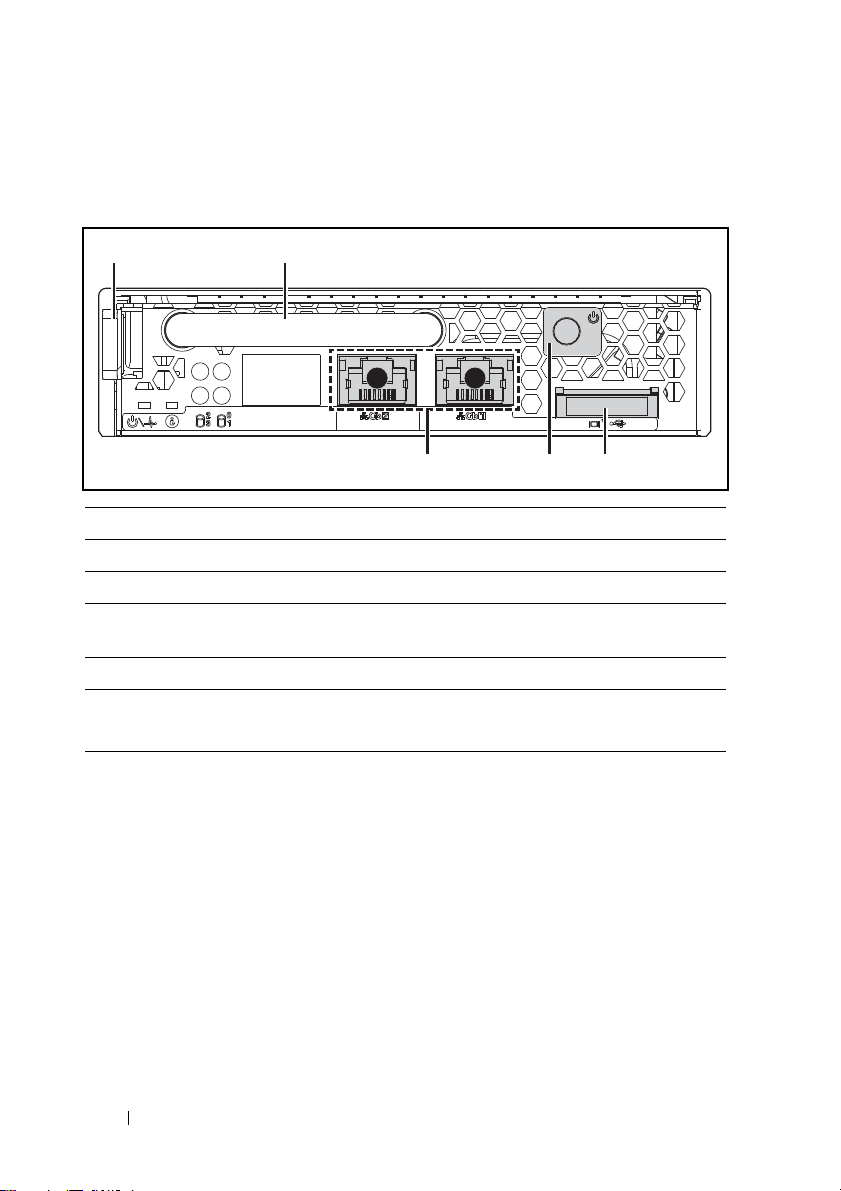
Front-Panel Features and Indicators
345
21
12
Figure 1-1. Sled Front Features (Rotated Counter-clockwise 90°)
Item Feature Description
1 Latch Press to release sled from chassis.
2 Handle Hold to pull sled out of chassis.
3 VGA/USB connector Custom port with custom cable
(USB [2] and video)
4 Power button ON/OFF button for sled
5 NIC LAN ports 10/100/1G NIC LAN connector 1
10/100/1G NIC LAN connector 2
Sled Population Rules
NOTE: The Dell PowerEdge C5000 is a blade enclosure supporting a Dell PowerEdge sled
system.
The following sled Stock Keeping Unit (SKU) is available for the PowerEdge
C5000 enclosure:
• A twelve sled SKU
For further information, see "Sled Configuration" on page 49.
8 About the System
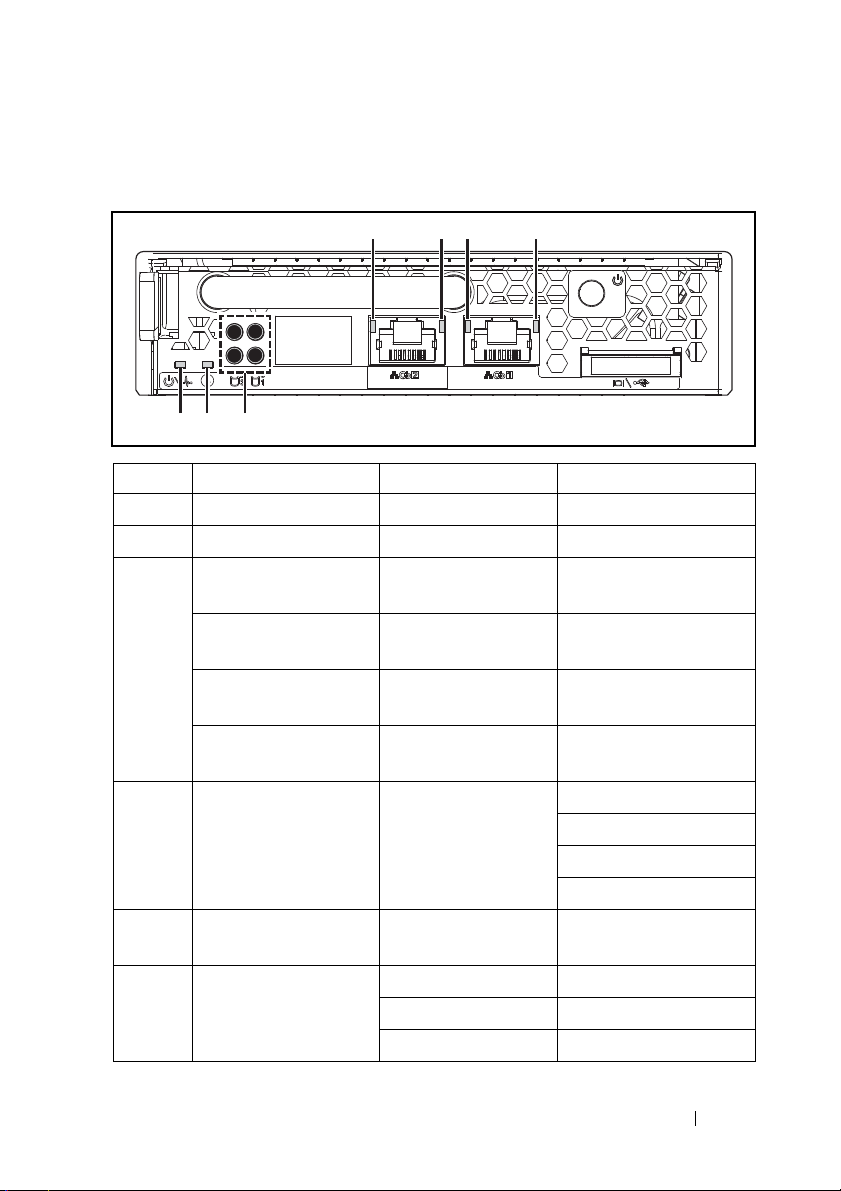
Sled LED Description
4321
567
0132
Figure 1-2. Sled LEDs (Rotated Counter-clockwise 90°)
Item Feature Status Description
4, 2 LAN link LED OFF No link
3, 1 LAN activity LED OFF No activity
LAN link LED
LAN activity LED
LAN link LED
LAN activity LED
LAN link LED
LAN activity LED
LAN link LED
LAN activity LED
5 Hard-drive activity
LEDs
6 Identity LED Blue Identifies the sled on
7 Power/Status Green Normal operation
Green
OFF
Green
OFF
Blinking green
Green
Blinking green
Amber
Link
No activity
Link
Activity 10 Mb
Link
Activity 100 Mb
Link
Activity 1G
Blinking green Hard-drive 0 active
Hard-drive 1 active
Hard-drive 2 active
Hard-drive 3 active
command
Blinking amber Fault with power off
OFF Power off
About the System 9

10 About the System

2
Using the System Setup Program
Setup Menu
The computer employs the latest AMI Core BIOS, which is stored in Flash
memory. The Flash memory supports the Plug and Play specification, and
contains a BIOS Setup program, the Power On Self Test (POST) routine, and
the PCI auto-configuration utility.
This system supports system BIOS shadowing which enables the BIOS to
execute from 64-bit onboard write-protected DRAM.
You can configure items such as:
• Hard drives and peripherals
• Password protection
• Power management features
The Setup utility should be executed under the following conditions:
• When changing the system configuration
• When a configuration error is detected by the system and you are
prompted to make changes to the Setup utility
• When redefining the communication ports to prevent any conflicts
• When changing the password or making other changes to the security
setup
NOTE: Only items in brackets [ ] can be modified. Items that are not in brackets are
display only.
Using the System Setup Program 11

BIOS Setup Options at Boot
You can initiate SETUP by pressing the respective keys during the POST:
<F2> Enter the BIOS Setup
Console Redirection
The console redirection allows a remote user to diagnose and fix problems on
a server, which has not successfully booted the operating system (OS). The
centerpiece of the console redirection is the BIOS Console. The BIOS
Console is a Flash ROM-resident utility that redirects input and output over
a serial or modem connection.
The BIOS supports console redirection to a serial port. If serial port based
headless server support is provided by the system, the system must provide
support for redirection of all BIOS driven console I/O to the serial port. The
driver for the serial console must be capable of supporting the functionality
documented in the ANSI Terminal Definition.
Enable/Disable Console Redirection
The console redirection function can be enabled/disabled in the BIOS Setup
menu.
COM1 for console redirection
COM2 for Serial over LAN
Value Description
00H Console Redirection function disable
01H Console Redirection to COM1 (3F8H)
Configuring Special Keys
Console redirection uses ANSI terminal emulation, which is limited to basic
ASCII characters. There are no function keys, arrow keys, or control keys in
this character set. However, the PowerEdge C5000 software requires the use
of function keys and control keys for ordinary functions. You can emulate a
function key or control key by using a special key sequence called an escape
sequence, to represent a specific key.
12 Using the System Setup Program

For console redirection, an escape sequence starts with an escape character.
This character can be entered in a variety of different ways depending on the
requirements of your terminal emulation software. For example, 0x1b, ^[,
and <Esc> refer to the same escape character.
The following table lists the escape sequence that must be sent to represent a
special key or command.
Key ANSI Escape Sequence Windows Platform Design Note
F1 <ESC><Shift>op <ESC>1
F2 <ESC><Shift>oq <ESC>2
F3 <ESC><Shift>or <ESC>3
F4 <ESC><Shift>os <ESC>4
F5 <ESC><Shift>ot <ESC>5
F6 <ESC><Shift>ou <ESC>6
F7 <ESC><Shift>ov <ESC>7
F8 <ESC><Shift>ow <ESC>8
F9 <ESC><Shift>ox <ESC>9
F10 <ESC><Shift>oy <ESC>0
F11 <ESC><Shift>oz <ESC>!
F12 <ESC><Shift>oa <ESC>@
Home <ESC>[<Shift>h <ESC>h
End <ESC>[<Shift>k <ESC>k
Ins <ESC>[2 <ESC>+
Del <ESC>[3 <ESC>-
Page Up <ESC>[5 <ESC>?
Page Down <ESC>[6 <ESC>/
Reset <ESC><Shift>b <ESC>R<ESC>r<ESC>R
Using the System Setup Program 13

The Legend Bar
The legend bar is at the side of the Setup screen. The keys in the legend bar
allow you to navigate through the various setup menus. The following table
lists the keys found in the legend bar with their corresponding alternates and
functions.
Legend Key Function
F1 General Help
? Select Screen
or Select Item
+ or - Change Option/Field
Enter Go to Sub Screen
Page Down Next Page
Page Up Previous Page
Home Go to Top of Screen
End Go to Bottom of Screen
F7 Discard Changes
F9 Load Optimal Default
F10 Save and Exit
Esc Exit
General Help
In addition to the Item Specific Help window, the Setup Utility also provides
a General Help screen. This screen can be called up from any menu by
pressing <F1>. The General Help screen lists the legend keys with their
corresponding alternates and functions. To exit the help window, press
<Enter> or <Esc>.
14 Using the System Setup Program

Access Level
The Access Level property controls who has access to the control (supervisor
or user).
Table 2-1 summarizes the effect of Access Level on a control.
Table 2-1. Access Level Summary
Password(s)
Installed
None N/A N/A View &
User Only User N/A View &
Supervisor
Only
Both Supervisor N/A View &
Both User None No Setup
Password
Entered
Supervisor N/A View &
User Access
Level Selected
by Supervisor
View Only Hidden View
Limited Hidden View
Full Hidden View &
Access
Level
0
Edit
Edit
Edit
Edit
Access
Access
Level
1
View &
Edit
View &
Edit
View &
Edit
View &
Edit
No Setup
Access
Only
Only
Edit
Access
Level
2
View &
Edit
View &
Edit
View &
Edit
View &
Edit
No Setup
Access
View
Only
View &
Edit
View &
Edit
Access
Level
3
View &
Edit
View &
Edit
View &
Edit
View &
Edit
No Setup
Access
View &
Edit
View &
Edit
View &
Edit
Using the System Setup Program 15

Main Menu
The Main menu is the screen that is first displayed on entering the BIOS
Setup. If an error occurs, the Error Manager screen is displayed.
BIOS SETUP UTILITY
Main Advanced Boot Server Security Exit
System Overview Use [ENTER, [TAB]
AMIBIOS
Version : 1.0.0
Build Date: 01/17/11
Product Information
Name :PowerEdge C5125
Asset Tag :2234567890
Service Tag :1234567
ePPID :12345678901234567890123
Or [SHIFT-TAB] to
a Field.
Use <-> to configure
system time.
select
Processor
AMD Phenom(tm) II X4 910e Processor
Speed :2500MHz
Count :4
System Memory
Size :2048MB
System Time[17:40:55]
System Date[Mon 05/21/2011]
16 Using the System Setup Program
,
+ ,
Ta b
F1
F10
ESC
Select Screen
Select Item
Change Field
Select Screen
General Help
Save and Exit
Exit

AMIBIOS
Option Description
Ver si on
Displays the BIOS version.
NOTE: Check this version number when updating BIOS from
the manufacturer.
Build Date
Displays the date the BIOS was created.
Product Information
Option Description
Name
Asset Tag
Service Tag
Electronic Piece Part
System product name.
System asset tag number.
System service tag number.
Information from PPID label.
Identification
(ePPID)
Processor
Option Description
Ty p e
Speed
Counter
Displays the type of processor installed on the system
board.
Displays the maximum speed of the processor.
Displays the number of installed processors.
System Memory
Option Description
Size
System Time
Displays how much memory (DRAM) is installed on
the system board.
Scroll to this item to adjust the time. Use [ENTER],
[TAB] or [SHIFT-TAB] to select a field. Use [+] or [-]
to configure system time.
Using the System Setup Program 17

Option Description
System Date
Scroll to this item to adjust the date. Use [ENTER],
[TAB] or [SHIFT-TAB] to select a field. Use [+] or [-]
to configure system date.
Control Group User Access Level
System Time Access Level 2
System Date Access Level 2
18 Using the System Setup Program

Advanced Menu
The Advanced screen provides an access point to configure several options.
On this screen, the user selects the option that is to be configured.
Configurations are performed on the selected screen, not directly on the
Advanced screen.
CAUTION:
system to malfunction. Unless you have experience adjusting these items, it is
recommended that you leave these settings at the default values. If making
settings to items on these pages causes your system to malfunction or prevents the
system from booting, open BIOS and choose "Load Optimal Defaults" in the Exit
menu to boot up normally.
Main Advanced Boot Server Security Exit
Advanced Settings Configure the CPU
Caution:Setting wrong values in below sections
• CPU Configuration
• SATA Configuration
• PCI Configuration
• USB Configuration
Making incorrect settings to items on these pages may cause the
BIOS SETUP UTILITY
may cause system to malfunction
,
Enter
F1
F10
ESC
Select Screen
Select Item
Go to Sub Screen
General Help
Save and Exit
Exit
Using the System Setup Program 19

CPU Configuration
Scroll to this item and press <Enter> to view the following screen:
BIOS SETUP UTILITY
Advanced
CPU Configuration
Module Version :13.65
AGESA Version :3.5.5.0
Physical Count :1
Logical Count :4
AMD Phenom II
Processor 910e
Revision :C2
Cache L1 :512KB
Cache L2 :2048KB
Cache L3 :6MB
Speed: :2500MHz
Able to Change Freq.
uCode Patch Level
Secure Virtual Machine Mode
PowerN ow
PowerC ap
L3 Power Control
Non Coherent HT Link Speed
NB Clk 2000MHz
:Yes
:0x1000086
[Enabled]
[Enabled]
[P-state 0]
[Enabled]
[2000MHz] *1
Enable/Disable
Secure Virtual Machine
Mode (SVM)
,
+,
F1
F10
ESC
Select Screen
Select Item
Change Option
General Help
Save and Exit
Exit
*1: [800MHz] [2000MHz]
NOTE: Default values shown
NOTE: C1E support - The current BIOS disables the Enhanced C1 State support
20 Using the System Setup Program

Options:
• Module Version : CPU module version.
• AGESA Version : AMD Generic Encapsulated Software Architecture
(AGESA) version number
.
• Physical Count : Number of physical CPUs.
• Logical Count : Number of logical CPUs
.
• Revision : Processor revision
•
•
•
Cache L1
Cache L2
Cache L3
: Information only. Displays the size of CPU L1.
: Information only. Displays the size of CPU L2.
: Information only. Displays the size of CPU L3.
• Speed : Processor speed
• Able to Change Freq : Whether or not the desired CPU is capable of
changing its FID/VID
• uCode Patch Level : Shows processor micro code level
.
.
• Secure Virtual Machine Mode : Enable/Disable Secure Virtual Machine
Mode(SVM)
.
• PowerNow : Enable/disable the generation of ACPI _PPC, _PSS, and
_PCT objects.
• PowerCap : This option can decide the highest performance P-state in
OS.
• L3 Power Control : Enabled: The clock to idle subcaches in the L3 is
stopped
.
• Non Coherent HT Link Speed : Non-coherent HyperTransport
Control Group User Access Level
Secure Virtual Machine Mode Access Level 1
PowerNow Access Level 1
PowerCap Access Level 1
L3 Power Control Access Level 1
Non Coherent HT Link Speed Access Level 1
Using the System Setup Program 21

SATA Configuration
Scroll to this item and press <Enter> to view the following screen:
BIOS SETUP UTILITY
Advanced
SATA Configuration Options
OnChip SATA Type
[Native IDE]*1
Native
AHCI
IDE
•SATA Port0
•SATA Port1
•SATA Port2
•SATA Port3
Power Saving Features
[Hard Disk]
[Not Detected]
[Not Detected]
[Not Detected]
[Disabled]*2
,
Enter
F1
F10
ESC
Select Screen
Select Item
Go to Sub Screen
General Help
Save and Exit
Exit
*1: [Native IDE] [AHCI]
*2: [Enable] [Disabled].
Options include:
• [Native IDE] - Supports up to four SATA ports.
• [AHCI] -Supports all SATA ports using the Advanced Host Controller
Interface.
22 Using the System Setup Program

SATA Port0-3: [Not Detected][Hard Disk][ATAPI CDROM] While entering
setup, BIOS auto detects the presence of SATA devices. This displays the
status of auto detection of SATA devices. This item displays information only
and is unavailable when AHCI Mode is enabled.
Power Saving Features: Disable/Enable power saving features in the server
board.
Control Group User Access Level
OnChip SATA Type Access Level 1
Power Saving Features Access Level 1
PCI Configuration
Scroll to this item and press <Enter> to view the following screen. The PCI
Screen provides fields to configure the onboard NIC controllers.
BIOS SETUP UTILITY
Advanced
PCI Configuration iSCSI Remove Boot if enable
iSCSI boot, must disable PXE boot
iSCSI Remote Boot
[DISABLED]*1
NIC1 - 82576EB
NIC2 - 82576EB
IOMMU
•Active State Power
Management
Configuration
[Enabled with PXE]*2
[Enabled with PXE]*2
[DISABLED]*1
*1: [Disabled] [Enabled]
,
+,
F1
F10
ESC
Using the System Setup Program 23
Select Screen
Select Item
Change Option
General Help
Save and Exit
Exit

*2: [Disabled] [Enabled with PXE] [Enabled without PXE]
*3: [Disabled] [Enabled with PXE] [Enabled without PXE]
NIC1 - Intel 82576EB: [Disabled][Enabled with PXE][Enabled without
PXE]
NIC2 - Intel 82576EB: [Disabled][Enabled with PXE][Enabled without
PXE]
Control Group User Access Level
iSCSI Remote Boot Access Level 1
NIC1 – 82576EB Access Level 1
NIC1 – 82576EB Access Level 1
IOMMU Access Level 1
24 Using the System Setup Program

Active State Power Management Configuration
Scroll to this item and press <Enter> to view the following screen:
BIOS SETUP UTILITY
Advanced
Active State Power Management Configuration Active State Power
Management (ASPM).
Onboard LAN ASPM [Disabled] *1
NB-SB Link ASPM [L1] *2
,
+,
F1
F10
ESC
Select Screen
Select Item
Change Options
General Help
Save and Exit
Exit
*1: Disabled/L0s/L1/L0s & L1/L0s Downstream/L0s Downstream + L1
*2: Disabled/L1
Control Group User Access Level
Onboard LAN ASPM Access Level 1
NB-SB Link ASPM Access Level 1
Using the System Setup Program 25

USB Configuration
Scroll to this item and press <Enter> to view the following screen:
BIOS SETUP UTILITY
Advanced
USB Configuration Enables support for legacy
USB. AUTO option disables
legacy support if no USB
devices are connected.
Module Version - 2.24.5-13.4
USB Devices Enabled:
1 Keyboard, 1 Mouse, 1 Hub, 1 Drive
Legacy USB Support [Enabled] *1
• USB Mass Storage Device Configuration
USB PORT 0 (Front 0) [Enabled]
USB PORT 1 (Front 1) [Enabled]
USB PORT 2 (BMC) [Enabled] *2
USB PORT 3 (SSD) [Enabled]
,
+,
F1
F10
ESC
Select Screen
Select Item
Change Options
General Help
Save and Exit
Exit
*1: [Disabled] [Enabled] [Auto]
*2: Internal USB connector.
This menu enables you to configure USB devices.
USB Devices Enabled: displays USB devices currently detected.
USB PORT 2 (BMC): internal port.
26 Using the System Setup Program

Legacy USB Support:
Control Group User Access Level
Legacy USB Support Access Level 1
USB PORT 0(Front 0) Access Level 1
USB PORT 1(Front 1) Access Level 1
USB PORT 2(BMC) Access Level 1
USB PORT 3(SSD) Access Level 1
Using the System Setup Program 27

Boot Menu
This page enables you to set POST boot parameters.
Scroll to this item and press <Enter> to view the following screen:
BIOS SETUP UTILITY
Boot
Boot Settings Configure Settings during
System Boots.
• Boot Settings Configuration
• Boot Device Priority
•Network Device
Enter
F1
F10
ESC
Select Screen
Select Item
Go to Sub Screen
General Help
Save and Exit
Exit
28 Using the System Setup Program

Boot Settings Configuration
Select this item and press Enter to view the following submenu items:
BIOS SETUP UTILITY
Boot
Boot Settings ConfigurationAllows BIOS to skip
Quick Boot
Quiet Boot
Wait For ’F1’ If Error
Force PXE First
Force PXE First Boot Only
Force USB First
[Enabled]
[Enabled]
[Disabled]
[Enabled] *1
[Disabled]
[Disabled]
certain tests while
booting. This will decrease
the time needed to boot
the system.
,
+,
F1
F10
ESC
Select Screen
Select Item
Change Option
General Help
Save and Exit
Exit
st
*1: [Disabled] [Enabled] (If you enable PXE first, the 1
boot device will set
to PXE. Disable PXE first, the device priority will not change).
Quick Boot: enable this item to allow BIOS to skip certain tests during the
POST, which will decrease boot up time.
Quiet Boot: enable this item to display the OEM logo instead of POST
messages. When disabled, normal POST messages appear.
Wait For 'F1' If Error: enable this item to have the system prompt you to
press F1 if an error occurs. This enables you to view the error.
Force PXE First: Enable and disable this item to force a network boot (PXE).
Force PXE Boot Only: Enable/Disable PXE to be the Only boot device.
Using the System Setup Program 29

Force USB First: Enable/Disable USB to be the first boot device, the priority
is higher than PXE.
Control Group User Access Level
Quick Boot Access Level 1
Quiet Boot Access Level 1
Wait For ‘F1’ If Error Access Level 1
Force PXE First Access Level 1
Force PXE Boot Only Access Level 1
Force USB First Access Level 1
30 Using the System Setup Program
 Loading...