

Dell PowerEdge C5125 User Manual [en, es, fr]

Dell PowerEdge C5125
Getting Started
With Your System
Guide de mise en route
Primeiros passos com o sistema
Procedimientos iniciales con el sistema


Dell PowerEdge C5125
Getting Started
With Your System
Regulatory Model: B04S

Notes, Cautions, and Warnings
NOTE: A note indicates important information that will help a user make better use
of a computer system.
CAUTION: A caution indicates potential damage to hardware or loss of data is
instructions are not followed.
WARNING: A WARNING indicates a potential for property damage, personal
injury, or death.
____________________
Information in this publication is subject to change without notice.
© 2011 Dell Inc. All rights reserved.
Reproduction of these materials in any manner whatsoever without the written permission of Dell Inc.
is strictly forbidden.
™
Trademarks used in this text: Dell
®
, AMD Phenom™, and AMD Athlon™ are trademarks of Advanced Micro Devices, Inc.
AMD
Microsoft
in the United States and/or other countries. Red Hat
trademarks of Red Hat, Inc. in the United States and/or other countries. SUSE™ is a trademark of
Novell Inc. in the United States and other countries. Citrix
registered trademarks or trademarks of Citrix Systems, Inc. in the United States and/or other countries.
VMware
countries.
Other trademarks and trade names may be used in this publication to refer to either the entities claiming
the marks and names or their products. Dell Inc. disclaims any proprietary interest in trademarks and
trade names other than its own.
®
and Windows® are either trademarks or registered trademarks of Microsoft Corporation
®
is a registered trademarks or trademarks of VMWare, Inc. in the United States or other
, the DELL logo, and PowerEdge™ are trademarks of Dell Inc.
®
and Red Hat Enterprise Linux® are registered
®
, Xen®, and XenServer® are either
Regulatory Model B04S
March 2011 P/N 00XMM Rev. A00
CAUTION: Restricted Access Location
This server is intended for installation only in restricted access locations as
defined in Cl. 1.2.7.3 of IEC 60950-1: 2001 where both these conditions
apply:
• Access can only be gained by service persons or by users who have been
instructed about the reasons for the restrictions applied to the location and
about any precautions that shall be taken.
• Access is through the use of a tool or lock and key, or other means of
security, and is controlled by the authority responsible for the location.
Installation and Configuration
WARNING: Before performing the following procedure, review and follow the
safety instructions that came with the system.
Unpacking the System
Unpack your system and identify each item.
Installing the Tool-Less Rail Solution
WARNING: Whenever you need to lift the system, get others to assist you.
To avoid injury, do not attempt to lift the system by yourself.
WARNING: The system is not fixed to the rack or mounted on the rails. To avoid
personal injury or damage to the system, you must adequately support the system
during installation and removal.
WARNING: To avoid a potential electrical shock hazard, a third wire safety
grounding conductor is necessary for the rack installation. The rack equipment
must provide sufficient airflow to the system to maintain proper cooling.
CAUTION: When installing rails in a square-hole rack it is important to ensure
that the square peg slides through the square holes.
CAUTION: Square studs must be flush with the rack posts to install properly.
Installation and Configuration 3
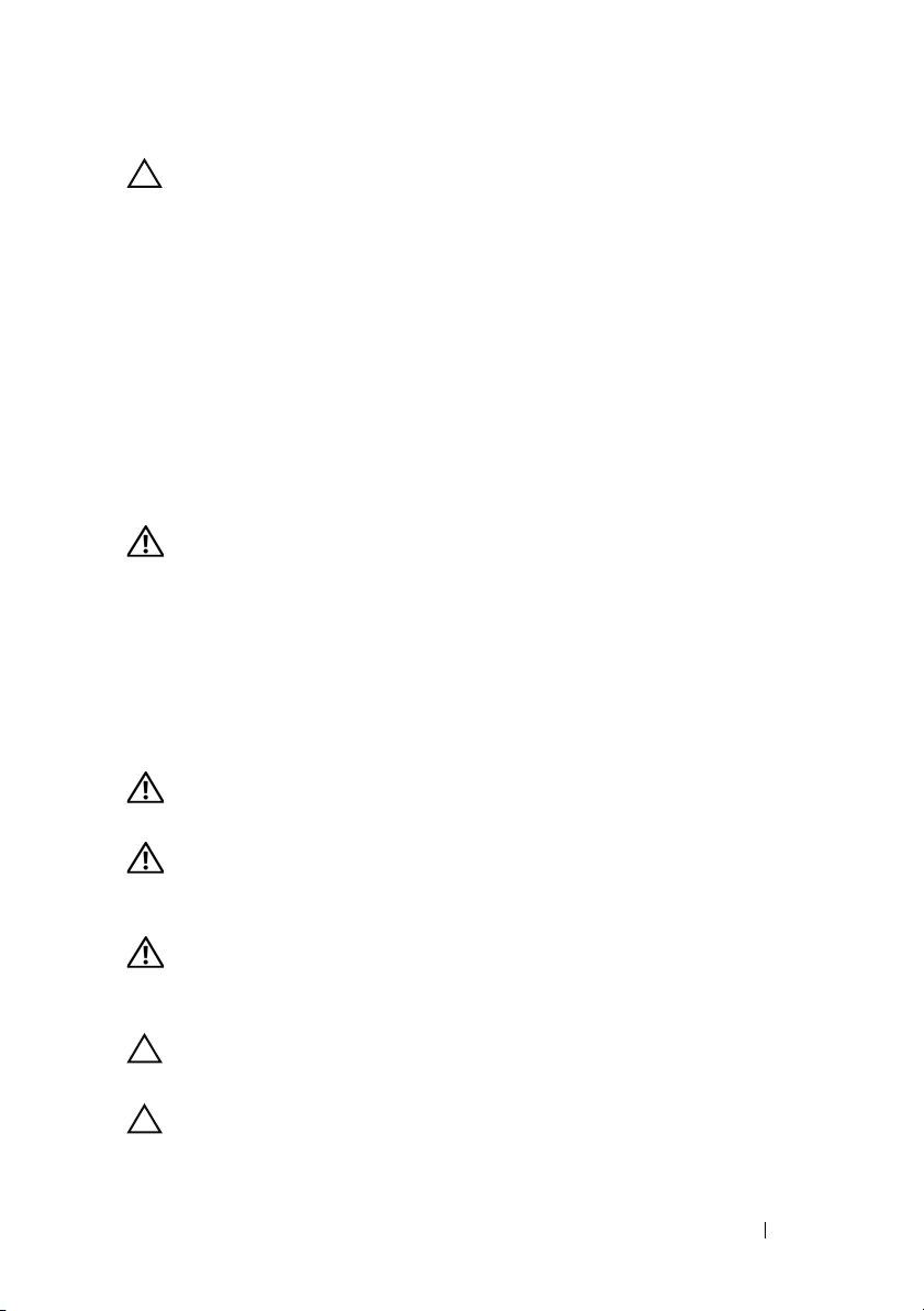
1
Pull on the latch release buttons on the end piece midpoints to open the
rail latches.
2
Align the end pieces of the rails on the vertical rack flanges to seat the pegs
in the bottom hole of the first U and the top hole of the second U. Engage
the back end of the rail until the latch locks in place.
NOTE: The rails can be used in both square-hole and round-hole racks.
Back
Front
4 Installation and Configuration
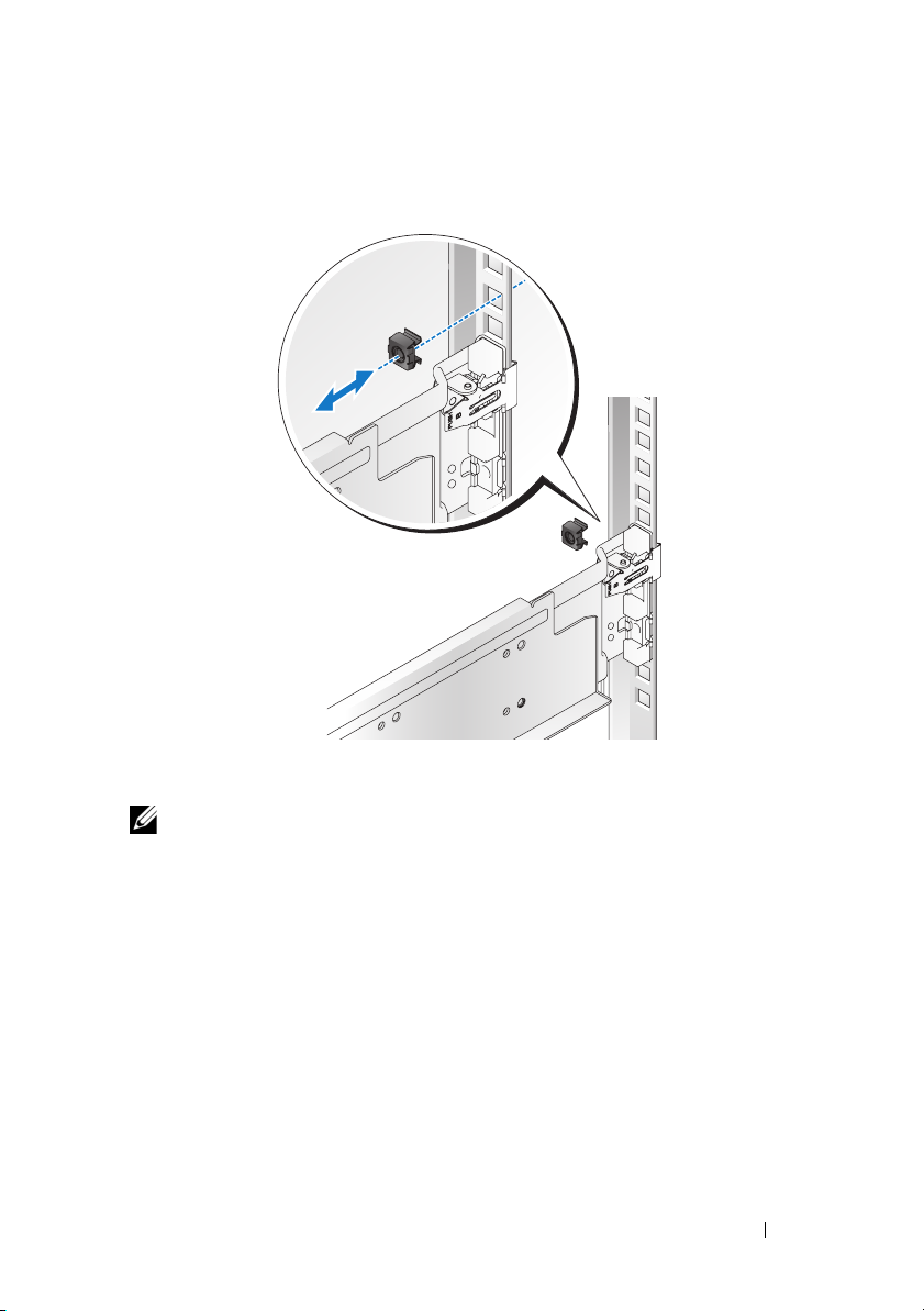
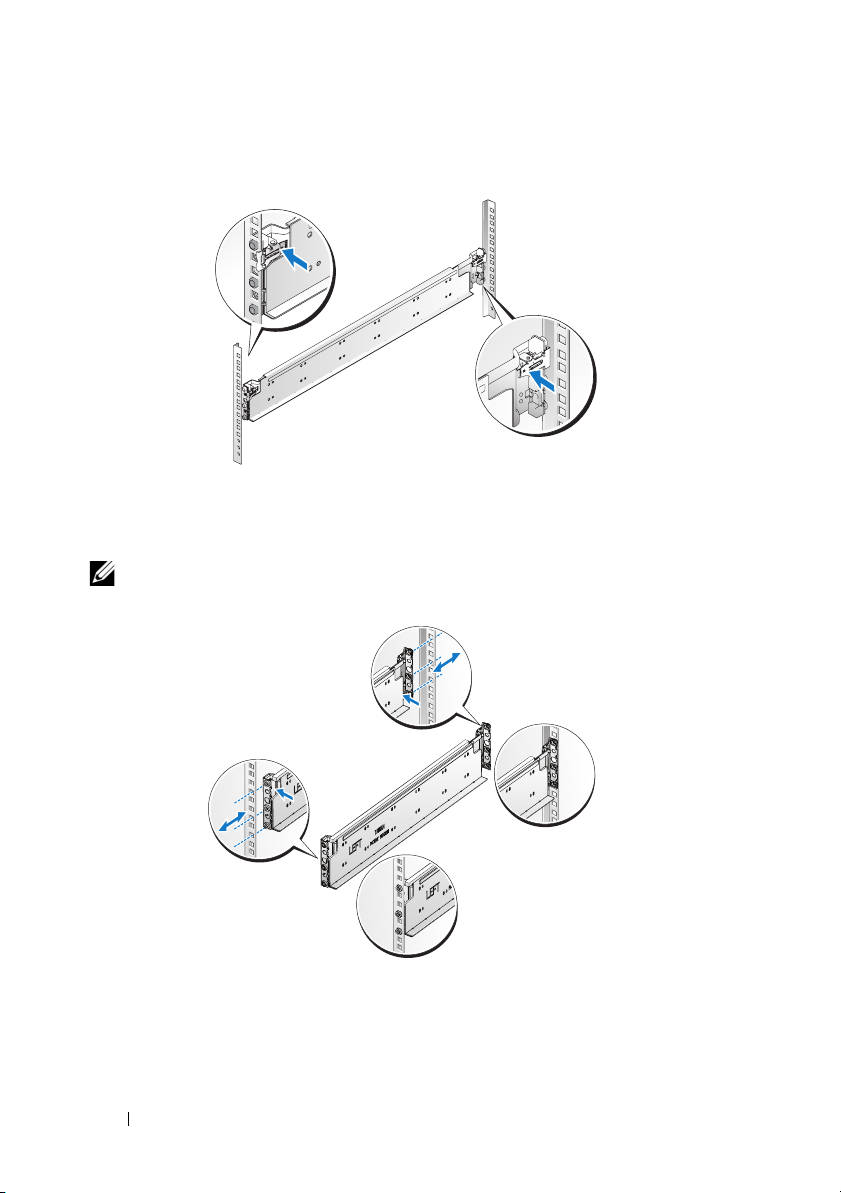
3
Insert the cage nut on the rack.
4
Repeat steps 1 to 4 to position and seat the front end piece on the vertical
flange.
NOTE: To remove the rails, pull on the latch release button on the end piece
midpoint and unseat each rail.
Installation and Configuration 5
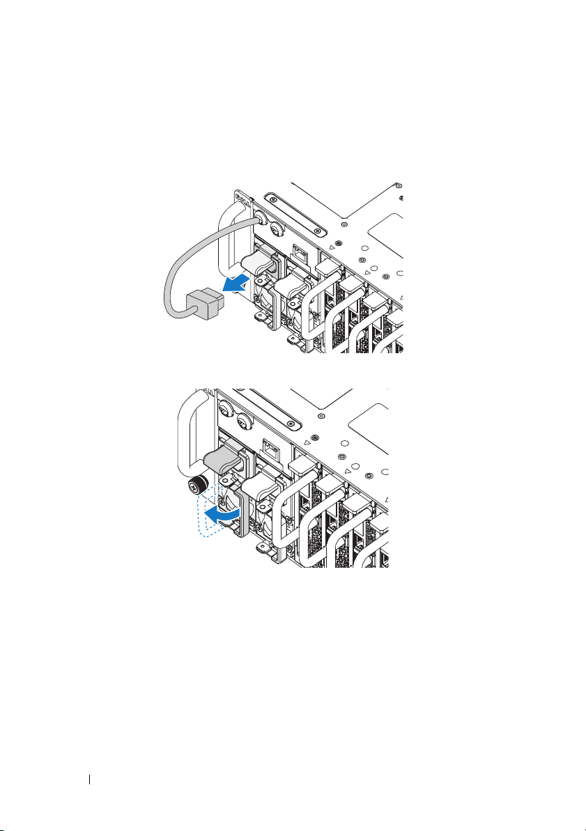
Installing the System
Empty the System Chassis
1
Unplug the power cable from the power supply unit.
.
2
Pull out the power supply unit handle.
6 Installation and Configuration
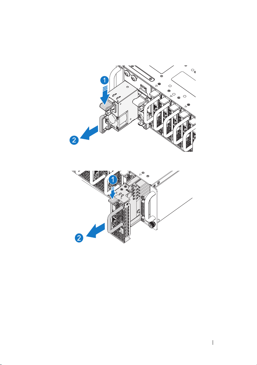
3
Press down on the release latch .
4
Pull the power supply unit out of the system .
5
Press the release latch down and pull the sled out of the system .
Installation and Configuration 7
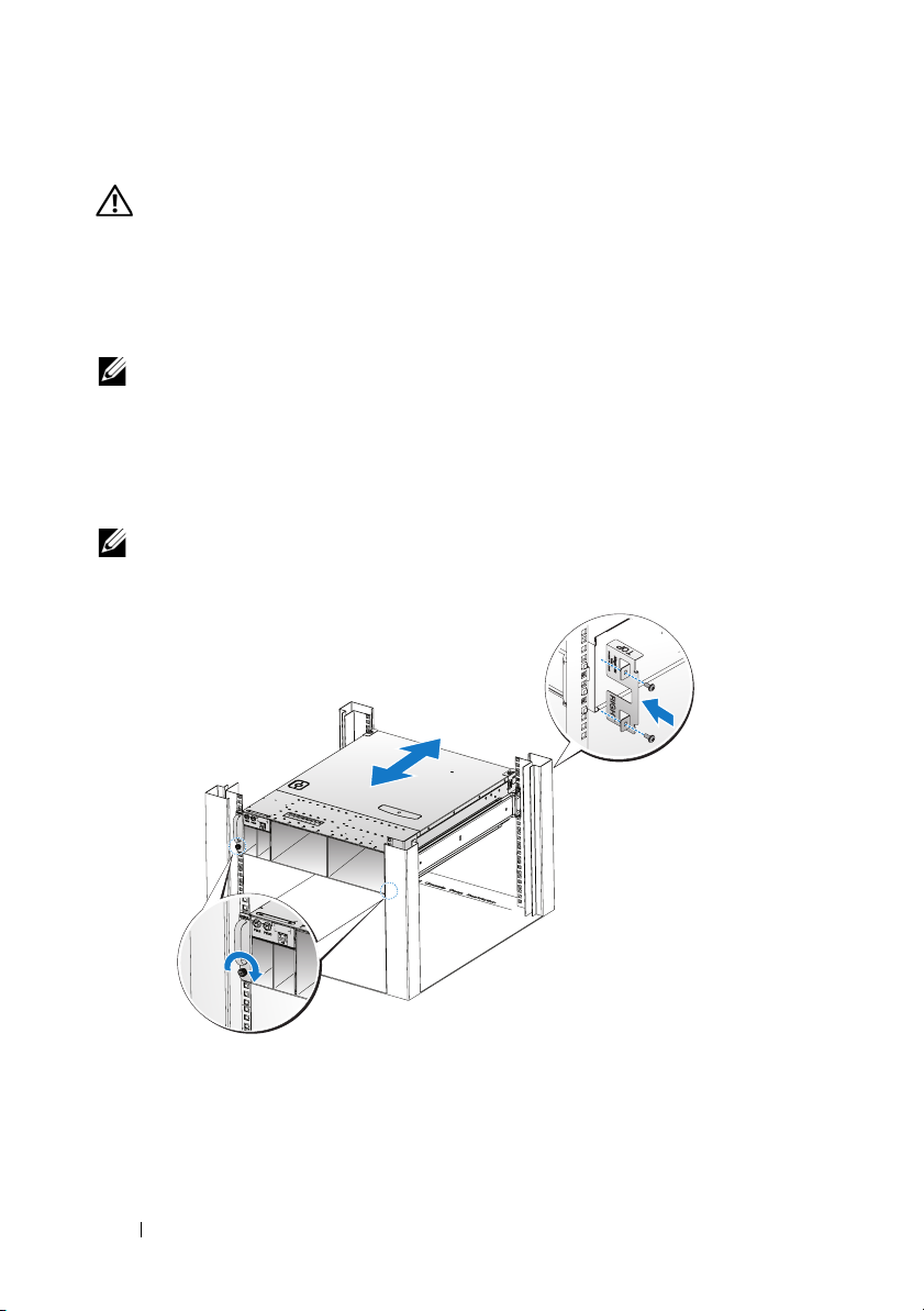
Install the System Into the Rack
WARNING: Whenever you need to lift the system, get others to assist you.
To avoid injury, do not attempt to lift the system by yourself.
1
Slide the system into the rack.
2
If present, remove the chassis stabilizer shipping bracket (optional) from
the rack.
NOTE: To transport systems already installed in the rack, ensure that the two
chassis stabilizer shipping brackets (optional) are in place.
3
Tighten the captive thumbscrews to secure the ears of the system to the
front of the rack.
4
Install the stopping bracket on the post and secure with M5 screws.
NOTE: Make sure the latch release mechanism is engaged correctly.
8 Installation and Configuration
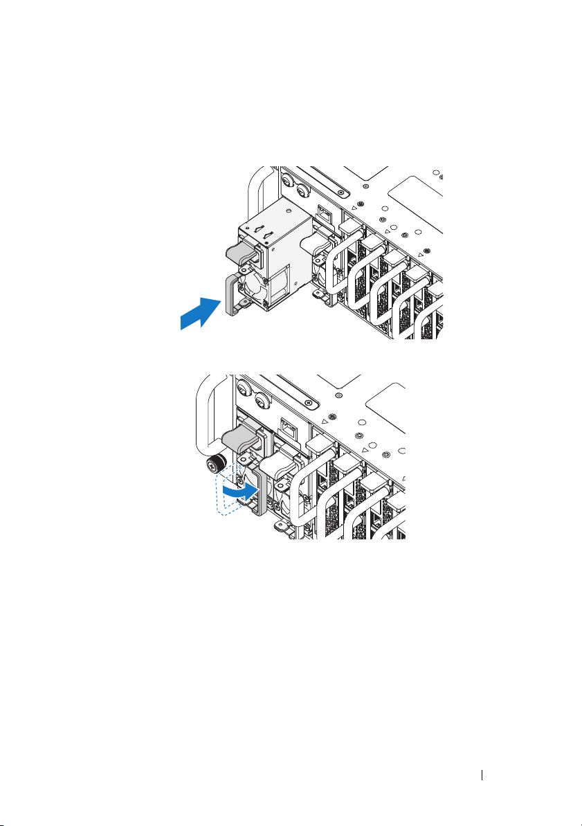
Populate the System
1
Push the power supply unit into the system until flush with the case and
the release latch locks.
2
Close the power supply unit handle.
Installation and Configuration 9
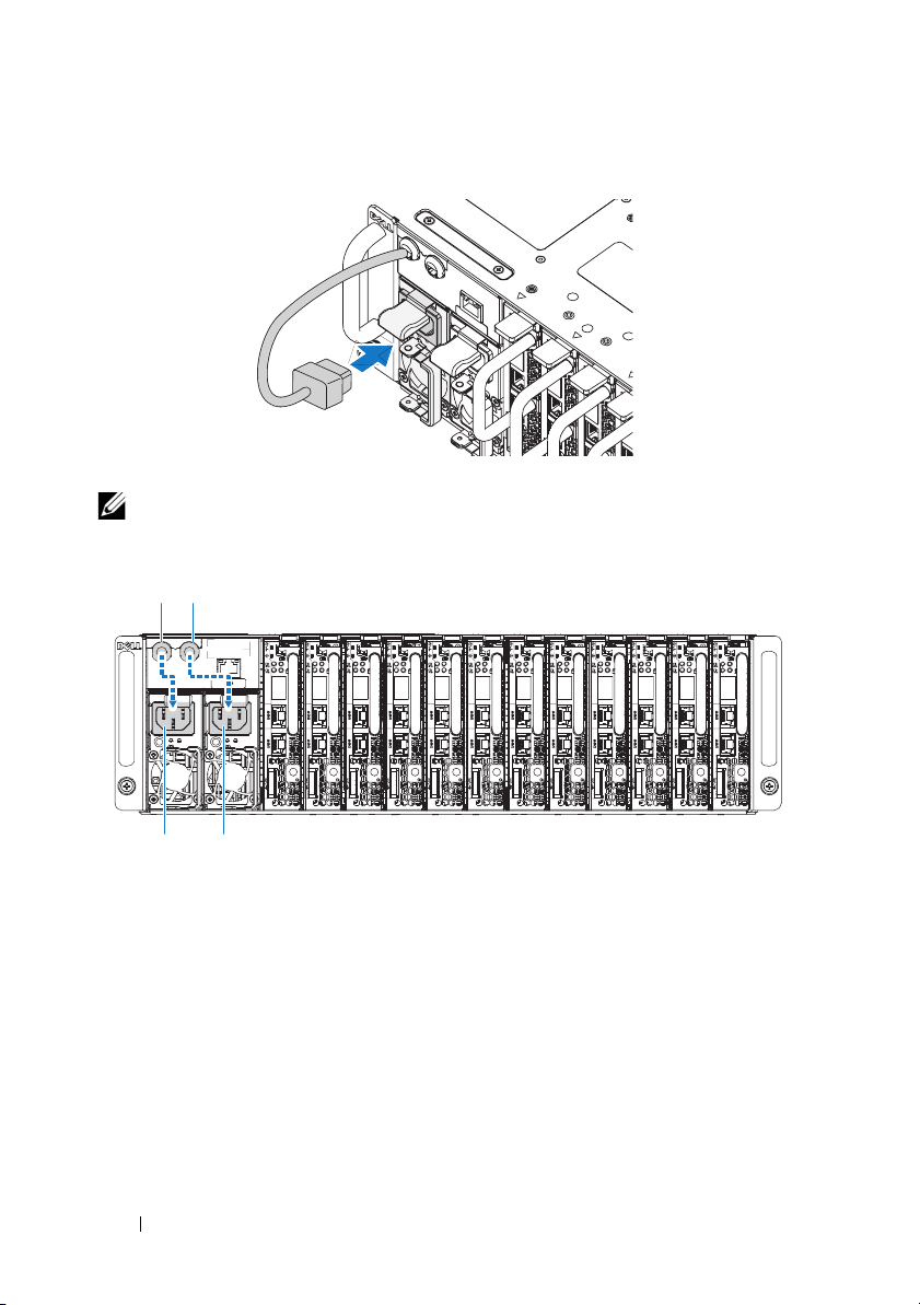
3
Plug the chassis power cable into the power supply unit.
NOTE: The correct configuration of the integral chassis AC power cables to the
PSU sockets is as shown in the following illustration.
PSU1 PSU2
PSU1 PSU2
10 Installation and Configuration
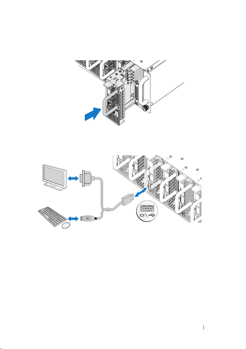
4
Install the sleds. Push the sled into the system until flush with the case and
the release latch locks.
Connecting the Keyboard, Mouse, and Monitor
The connector on the front of your system has an icon indicating which cable
to plug in. Connect a keyboard, mouse, or monitor (optional).
Installation and Configuration 11
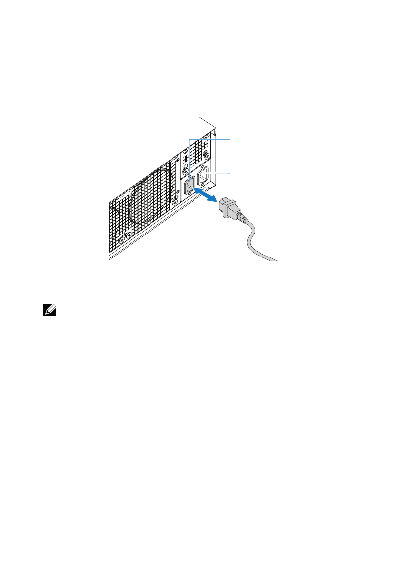
Connecting the Power Cables
1
On the back of the system, connect the mains power cable to the system’s
power socket.
AC Port 2
AC Port 1
2
Plug the other end of the power cables into a grounded electrical outlet or
a separate power source such as an uninterrupted power supply or a power
distribution unit.
NOTE:
AC Port 1 provides power to PSU1, ACP Port 2 provides power to PSU2. See
Populate the System step 3 for further information.
Turning On the System
When connected to a power source the system automatically powers on.
See the Using the Baseboard Management Controller Guide at
support.dell.com/manuals.
12 Installation and Configuration
Complete the Operating System Setup
To install an operating system for the first time, see the installation and
configuration documentation for your operating system. Be sure the
operating system is installed before installing hardware or software not
purchased with the system.
Supported Operating Systems
• Microsoft Windows Server 2008 Enterprise Edition Release 2 (64-bit)
• Microsoft Windows HPC 2008 Release 2
• Microsoft HyperV
• Red Hat Enterprise Linux 6.0 (64-bit)
• SUSE Linux Enterprise Server 11 SP1 (64-bit)
• Citrix XenServer Enterprise Edition 5.6
NOTE:
For the latest information on supported operating systems, see
support.dell.com.
Other Information You May Need
WARNING: See the safety and regulatory information that shipped with your
system. Warranty information may be included within this document or as a
separate document.
See the Hardware Owner’s Manual for information about system features,
troubleshooting, and component replacement. This document is available at
support.dell.com/manuals
See the Using the Baseboard Management Controller Guide at
support.dell.com/manuals.
NOTE: Always check for updates and read the updates first because they often
supersede information in other documents.
.
Installation and Configuration 13

Technical Specifications
Processor (Per System Board)
Processor type AMD Phenom II 910e, 2.6 GHz, 4 core
AMD Athlon II 610E, 2.4 GHz, 4 core
AMD Athlon II 260U, 1.6 GHz, 2 core
Expansion Bus (Per System Board)
Bus type PCI-E x1 connector for sideband signal
Internal PCIe Bus 1, SR5650(GPP3): PCI-E
x2,x1,x1,x1,x1,x4
3, SP5100: PCI 32/33
Memory (Per System Board)
Architecture UDDR3-1333
Memory module sockets 4 Quad Channel Unbuffered DDR3
800/1066/1333
Memory module capacities
Minimum RAM 2 GB
Maximum RAM 16 GB
Drives (Per System Board)
Hard drives SATAII (4 channels) support:
• 3.5" HDD x2 (Max Capacity 2 TB per
drive)
• 2.5" HDD x4 (Max Capacity 500 GB
per drive), SSD
Connectors (Per System Board)
Back
NIC
Serial (internal)
USB (through Y-cable)
Video (through Y-cable)
KVM over IP Port
2
1
2
1
1
14 Technical Specifications

Video
Video type AST2050
Video memory 128 MB DDR2 SDRAM
Power
AC power supply (per power supply)
Wattage
Vo lt ag e
Heat dissipation
Maximum inrush current
Physical
Sled system dimension (with 3.5" HDD)
Standard sled size:
VLP sled size:
Mainboard
Hard drives (3.5")
Hard drive board (3.5")
Sled system dimension (with 2.5" HDD)
Standard sled size:
VLP sled size:
Mainboard
Hard drives (2.5")
Hard drive board (3.5")
1400 W
200-240 VAC, 50/60 Hz, 9.6 A max
47.65 BTU/hr max
55 A max
613.3 mm x 124 mm x 42.45 mm
(8 sled)
613.3 mm x 124 mm x 27.7 mm
(12 sled)
1
2
1
613.3 mm x 124 mm x 42.45 mm
(8 sled)
613.3 mm x 124 mm x 27.7 mm
(12 sled)
1
4
1
Technical Specifications 15

Chassis
Height
Width
Depth
Weight (loaded: maximum weight)
Weig h t (e m pty )
Environmental
13 cm (5.1 in.)
44.7 cm (17.6 in.)
75 cm (29.5 in.)
8 sled configuration:
45 kg (99.21 lbs.)
12 sled configuration:
51.22 kg (112.92 lbs.)
8 sled configuration:
18.3 kg (40.34 lbs.)
12 sled configuration:
19.3 kg (42.55 lbs.)
NOTE: For additional information about environmental measurements for specific
system configurations, see the dell.com/environmental_datasheets.
Temperature
Operating
Airflow at maximum fan speed
(CFM) at peak temperature
Airflow at nominal fan speed (CFM)
at nominal temperature
Storage
Relative Humidity
Operating
Storage
10° to 35°C (50°F to 95°F) with a maximum
temperature gradation of 10°C (per hour)
140 CFM (8 sled)
285 CFM (12 sled)
40 CFM (8 sled)
60 CFM (12 sled)
–40° to 65°C (40°F to 149°F) with a
maximum temperature gradation of 20°C
per hour
20% to 80% (noncondensing) with a
maximum humidity gradation of 10%
per hour
5% to 95% (noncondensing)
16 Technical Specifications

Environmental (continued)
Maximum vibration
Operating
Storage
Maximum shock
Operating
Storage
Altitude
Operating
Storage
Airborne Contaminant Level
Class
0.26 Grms at 5–350 Hz
1.87 Grms at 10–500 Hz for 15 min
One shock pulse in the positive z axis (one
pulse on each side of the system) of 31 G for
2.6 ms in the operational orientation
Six consecutively executed shock pulses in
the positive and negative x, y, and z axes
(one pulse on each side of the system) of
71 G for up to 2 ms.
Six consecutively executed shock pulses in
the positive and negative x, y, and z axes
(one pulse on each side of the system) of
22 G faired square wave pulse with velocity
change at 200 inches/second
-16 to 3,048 m (-50 to 10,000 ft.)
NOTE: For altitudes above 2,950 feet, the
maximum operating temperature s derated to
1°F/550 ft.
-16 to 10, 600 m (-50 to 35,000 ft.)
G2 or lower as defined by ISA-S71.04-1985
Technical Specifications 17

18 Technical Specifications

Dell PowerEdge C5125
Guide de
mise en route
Modèle réglementaire : B04S
Remarques, précautions et avertissements
REMARQUE : une remarque indique des informations importantes qui peuvent
aider l'utilisateur à mieux utiliser son ordinateur.
PRÉCAUTION : une précaution indique un risque d'endommagement du matériel
ou de perte de données en cas de non respect des instructions.
AVERTISSEMENT: un AVERTISSEMENT indique un risque d'endommagement du
matériel, de blessures corporelles ou même de mort.
____________________
Les informations contenues dans cette publication sont sujettes à modification sans préavis.
© 2011 Dell Inc. tous droits réservés.
La reproduction de ce document, de quelque manière que ce soit, sans l'autorisation écrite de Dell Inc.
est strictement interdite.
™
Marques utilisées dans ce document : Dell
de Dell Inc. AMD
Devices, Inc. Microsoft
Corporation aux États-Unis et/ou dans d'autres pays. Red Hat
marques déposées de Red Hat, Inc. aux États-Unis et/ou dans d'autres pays. SUSE™ est une marque
de Novell Inc. aux États-Unis et dans d'autres pays. Citrix
déposées ou des marques de Citrix Systems, Inc. aux États-Unis et/ou dans d'autres pays. VMware
est une marque déposée ou une marque de VMware, Inc. aux États-Unis et dans d'autres pays.
D'autres marques et noms commerciaux peuvent être utilisés dans ce document pour faire référence
aux entités revendiquant la propriété de ces marques ou de ces noms de produits. Dell Inc. rejette tout
intérêt propriétaire dans les marques et les noms commerciaux autres que les siens.
®
, AMD Phenom™ et AMD Athlon™ sont des marques d'Advanced Micro
®
et Windows® sont des marques ou des marques déposées de Microsoft
, le logo DELL et PowerEdge™ sont des marques
®
et Red Hat Enterprise Linux® sont des
®
, Xen® et XenServer® sont des marques
®
Modèle réglementaire B04S
Mars 2011 N/P 00XMM Rév. A00

PRÉCAUTION : lieux à accès restreint
Ce serveur est conçu pour être installé uniquement dans des lieux à accès
restreint tels que définis dans Cl. 1.2.7.3 du document IEC 60950-1: 2001,
où les deux conditions suivantes s'appliquent :
• Seuls peuvent avoir accès le personnel d'entretien et les utilisateurs qui ont
été informés des motifs des restrictions appliquées au lieu et des
précautions à prendre.
• L'accès, qui se fait par l'intermédiaire d'un outil ou d'un verrou et
d'une clé, ou par d'autres moyens de sécurité, est contrôlé par le
responsable en charge du lieu.
Installation et configuration
AVERTISSEMENT: avant de commencer la procédure suivante, lisez les
consignes de sécurité fournies avec le système. Respectez ces consignes.
Déballage du système
Sortez le système de son emballage et identifiez chaque élément.
Installation sans outil des rails
AVERTISSEMENT: demandez toujours de l'aide avant de soulever le système.
N'essayez pas de le soulever seul, car vous risqueriez de vous blesser.
AVERTISSEMENT: le système n'est fixé ni au rack ni aux rails. Vous devez le
soutenir correctement au cours de l'installation et du retrait pour éviter de
l'endommager ou de vous blesser.
AVERTISSEMENT: afin d'éviter un éventuel choc électrique, assurez-vous de
disposer d'un troisième conducteur de mise à la terre pour l'installation du rack.
L'équipement du rack doit assurer un flux d'air suffisant pour bien refroidir le
système.
PRÉCAUTION : lorsque vous installez des rails dans un rack à trous carrés,
vérifiez que les taquets de fixation à tête carrée glissent bien dans les trous
carrés.
PRÉCAUTION : pour une installation correcte, les embouts carrés doivent être
alignés avec les montants du rack.
Installation et configuration 21
 Loading...