

Dell PowerEdge C5125 User Manual [en, ru, de, es, fr, cs, pl]

Dell PowerEdge C5125
תכרעמה םע הדובעה תליחת
Getting Started
With Your System
Začínáme se systémem
Guide de mise en route
Erste Schritte mit dem System
Τα πρώτα βήματα με το σύστημά σας
Rozpoczęcie pracy z systemem
Начало работы с системой
Procedimientos iniciales con el sistema
Sisteminizi Kullanmaya Başlarken


Dell PowerEdge C5125
Getting Started
With Your System
Regulatory Model: B04S

Notes, Cautions, and Warnings
NOTE: A note indicates important information that will help a user make better use
of a computer system.
CAUTION: A caution indicates potential damage to hardware or loss of data is
instructions are not followed.
WARNING: A WARNING indicates a potential for property damage, personal
injury, or death.
____________________
Information in this publication is subject to change without notice.
© 2011 Dell Inc. All rights reserved.
Reproduction of these materials in any manner whatsoever without the written permission of Dell Inc.
is strictly forbidden.
™
Trademarks used in this text: Dell
®
, AMD Phenom™, and AMD Athlon™ are trademarks of Advanced Micro Devices, Inc.
AMD
Microsoft
in the United States and/or other countries. Red Hat
trademarks of Red Hat, Inc. in the United States and/or other countries. SUSE™ is a trademark of
Novell Inc. in the United States and other countries. Citrix
registered trademarks or trademarks of Citrix Systems, Inc. in the United States and/or other countries.
VMware
countries.
Other trademarks and trade names may be used in this publication to refer to either the entities claiming
the marks and names or their products. Dell Inc. disclaims any proprietary interest in trademarks and
trade names other than its own.
®
and Windows® are either trademarks or registered trademarks of Microsoft Corporation
®
is a registered trademarks or trademarks of VMWare, Inc. in the United States or other
, the DELL logo, and PowerEdge™ are trademarks of Dell Inc.
®
and Red Hat Enterprise Linux® are registered
®
, Xen®, and XenServer® are either
Regulatory Model B04S
March 2011 P/N R5VKT Rev. A00
CAUTION: Restricted Access Location
This server is intended for installation only in restricted access locations as
defined in Cl. 1.2.7.3 of IEC 60950-1: 2001 where both these conditions
apply:
• Access can only be gained by service persons or by users who have been
instructed about the reasons for the restrictions applied to the location and
about any precautions that shall be taken.
• Access is through the use of a tool or lock and key, or other means of
security, and is controlled by the authority responsible for the location.
Installation and Configuration
WARNING: Before performing the following procedure, review and follow the
safety instructions that came with the system.
Unpacking the System
Unpack your system and identify each item.
Installing the Tool-Less Rail Solution
WARNING: Whenever you need to lift the system, get others to assist you.
To avoid injury, do not attempt to lift the system by yourself.
WARNING: The system is not fixed to the rack or mounted on the rails. To avoid
personal injury or damage to the system, you must adequately support the system
during installation and removal.
WARNING: To avoid a potential electrical shock hazard, a third wire safety
grounding conductor is necessary for the rack installation. The rack equipment
must provide sufficient airflow to the system to maintain proper cooling.
CAUTION: When installing rails in a square-hole rack it is important to ensure
that the square peg slides through the square holes.
CAUTION: Square studs must be flush with the rack posts to install properly.
Installation and Configuration 3
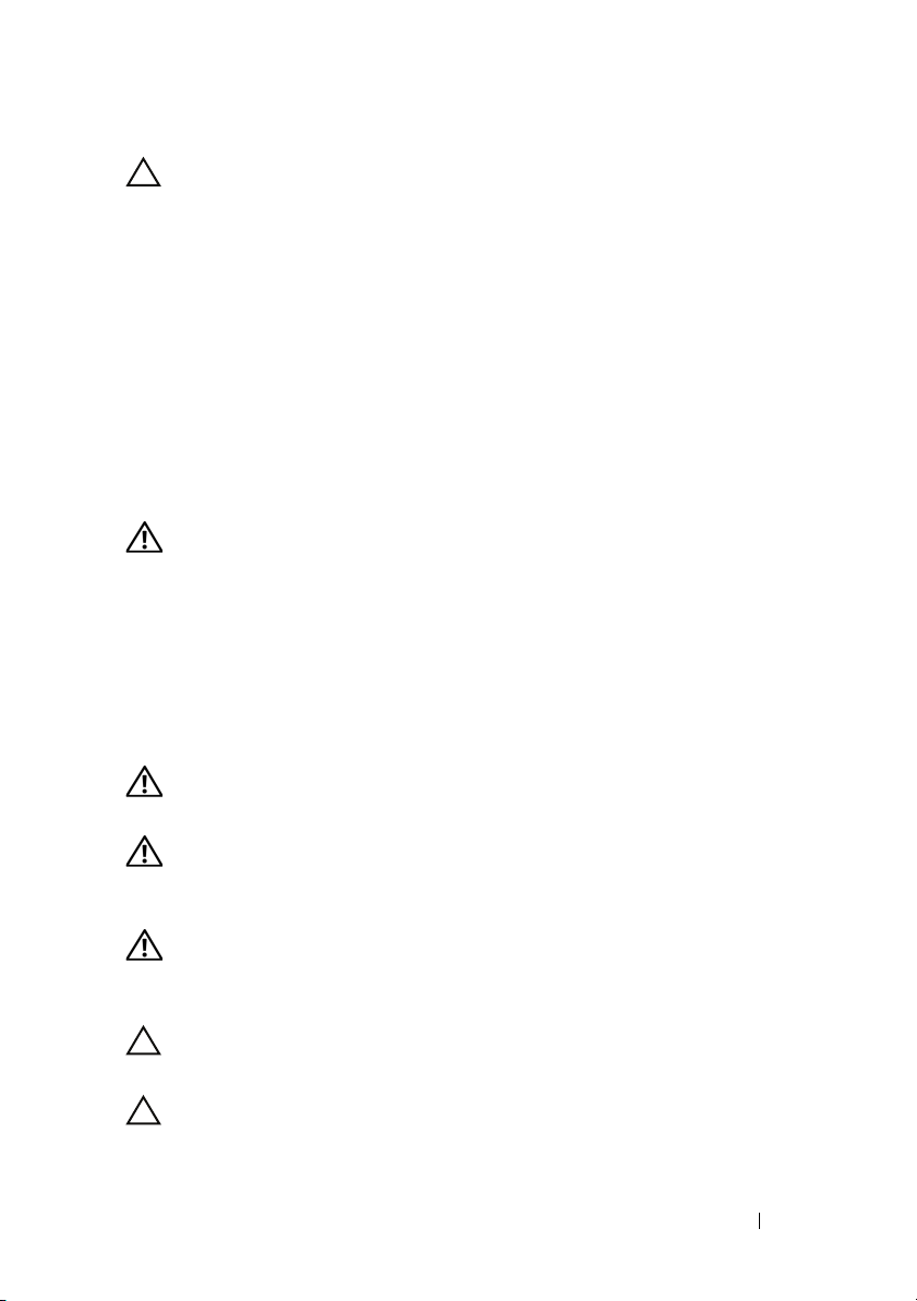
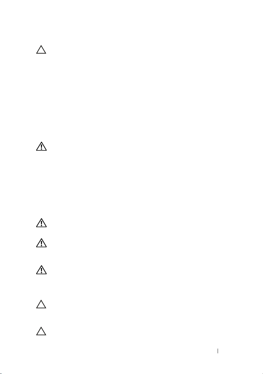
1
Pull on the latch release buttons on the end piece midpoints to open the
rail latches.
2
Align the end pieces of the rails on the vertical rack flanges to seat the pegs
in the bottom hole of the first U and the top hole of the second U. Engage
the back end of the rail until the latch locks in place.
NOTE: The rails can be used in both square-hole and round-hole racks.
Back
Front
4 Installation and Configuration
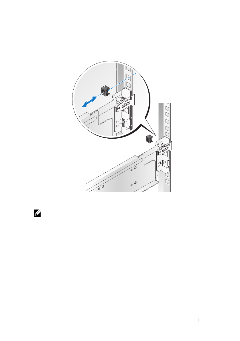
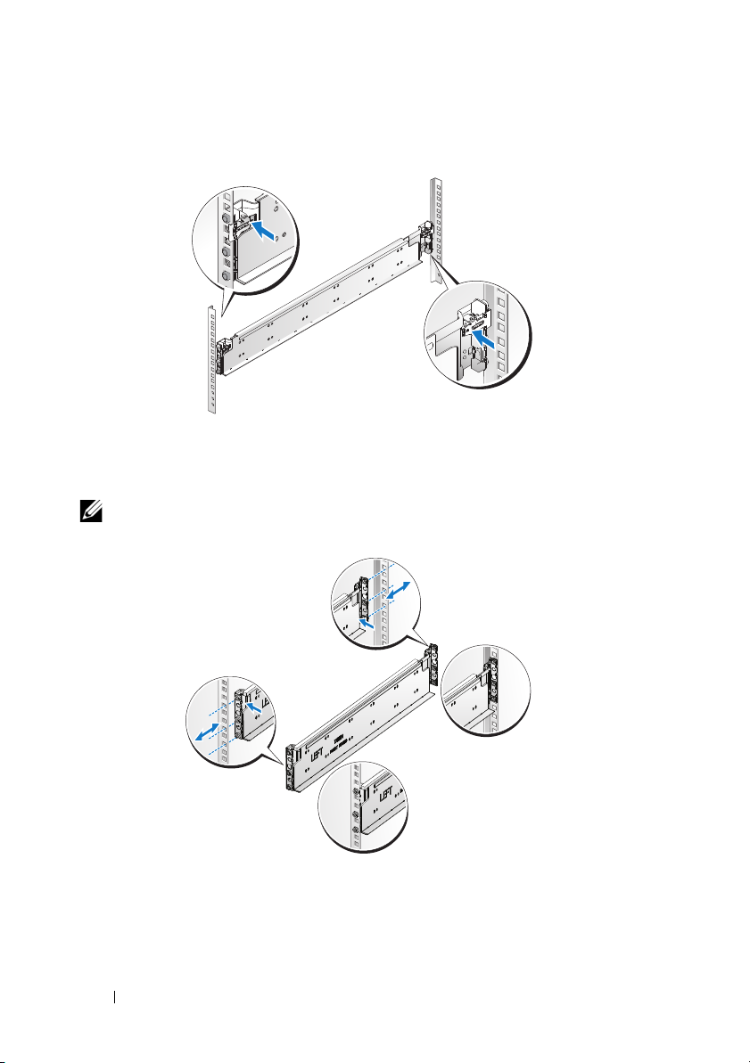
3
Insert the cage nut on the rack.
4
Repeat steps 1 to 4 to position and seat the front end piece on the vertical
flange.
NOTE: To remove the rails, pull on the latch release button on the end piece
midpoint and unseat each rail.
Installation and Configuration 5

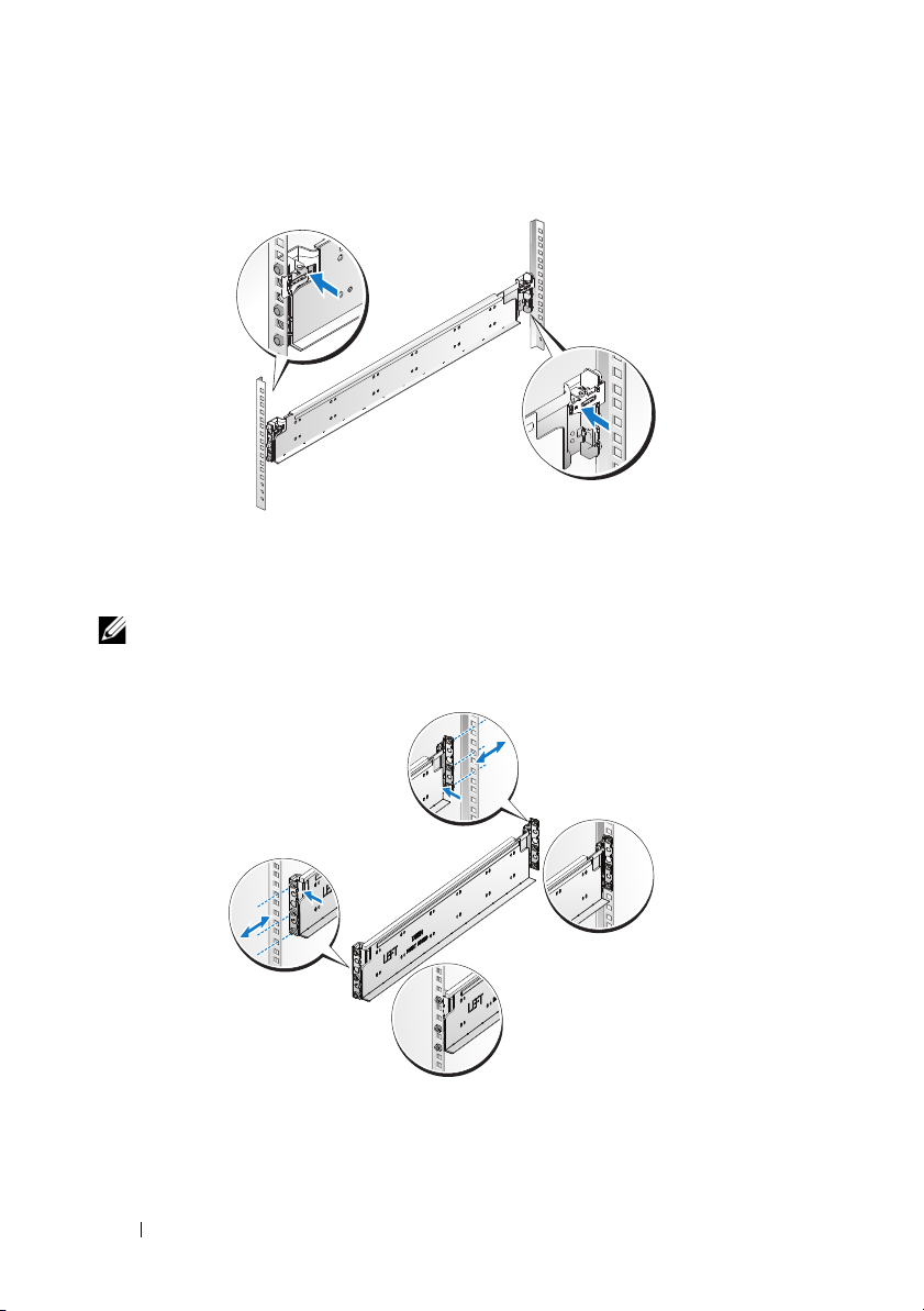
Installing the System
Empty the System Chassis
1
Unplug the power cable from the power supply unit.
.
2
Pull out the power supply unit handle.
6 Installation and Configuration

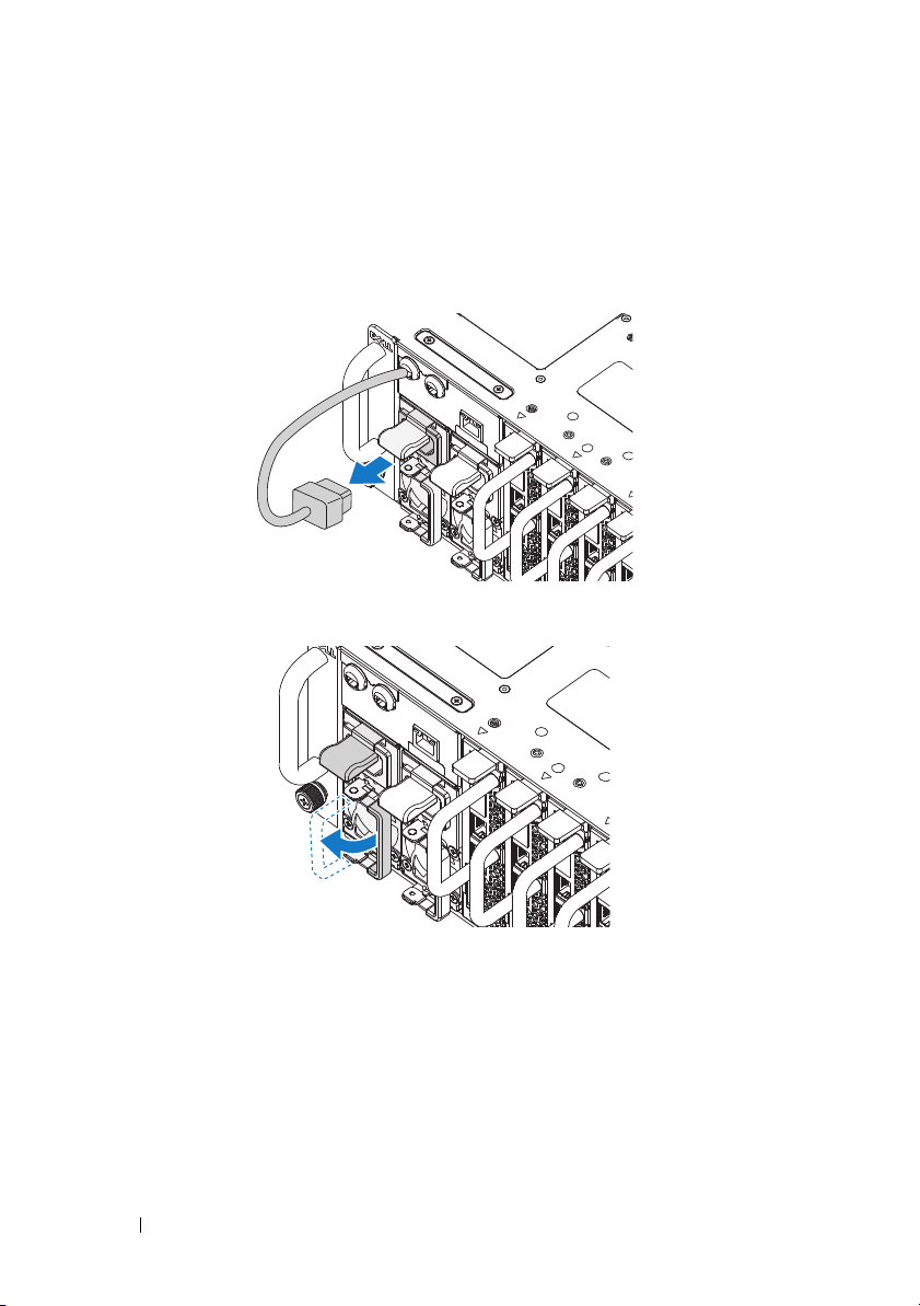
3
Press down on the release latch .
4
Pull the power supply unit out of the system .
5
Press the release latch down and pull the sled out of the system .
Installation and Configuration 7
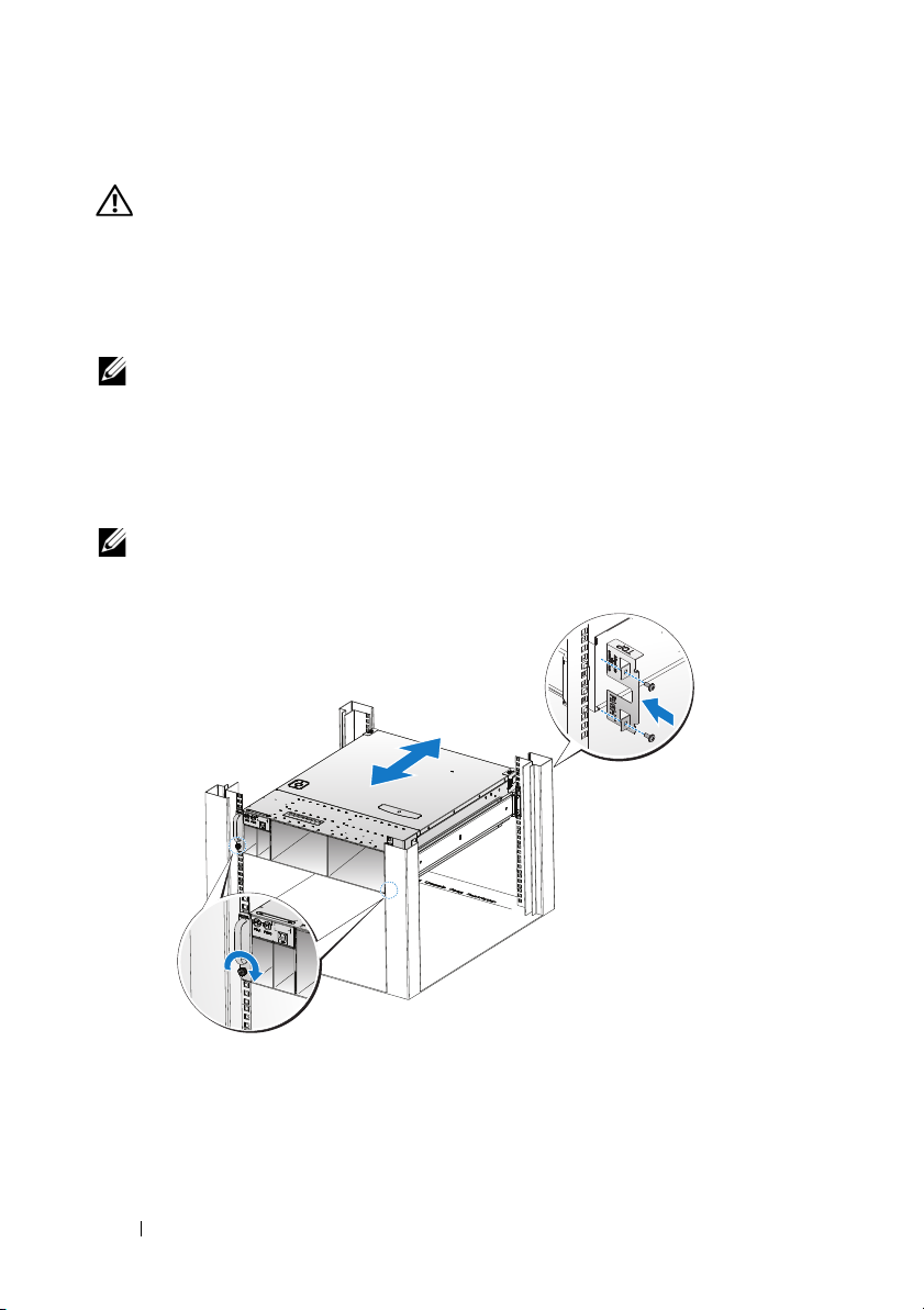
Install the System Into the Rack
WARNING: Whenever you need to lift the system, get others to assist you.
To avoid injury, do not attempt to lift the system by yourself.
1
Slide the system into the rack.
2
If present, remove the chassis stabilizer shipping bracket (optional) from
the rack.
NOTE: To transport systems already installed in the rack, ensure that the two
chassis stabilizer shipping brackets (optional) are in place.
3
Tighten the captive thumbscrews to secure the ears of the system to the
front of the rack.
4
Install the stopping bracket on the post and secure with M5 screws.
NOTE: Make sure the latch release mechanism is engaged correctly.
8 Installation and Configuration

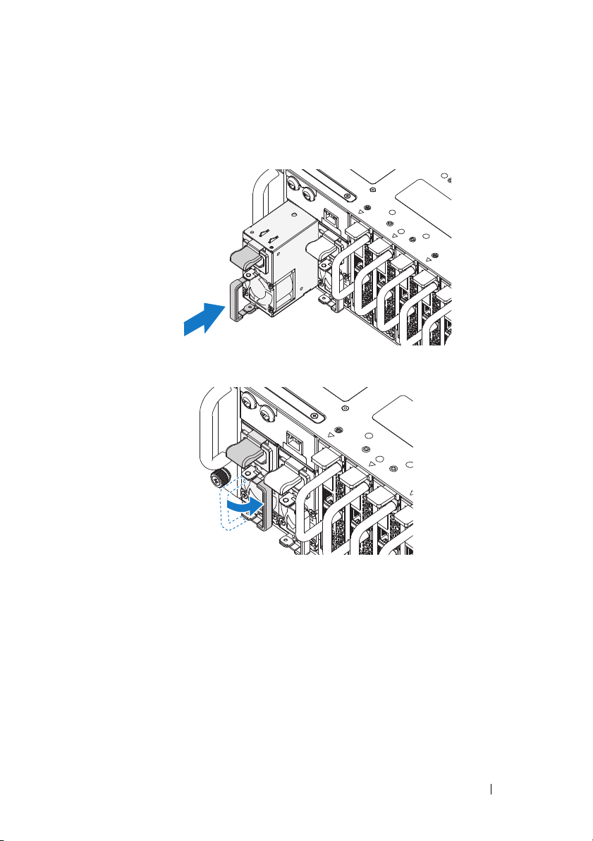
Populate the System
1
Push the power supply unit into the system until flush with the case and
the release latch locks.
2
Close the power supply unit handle.
Installation and Configuration 9
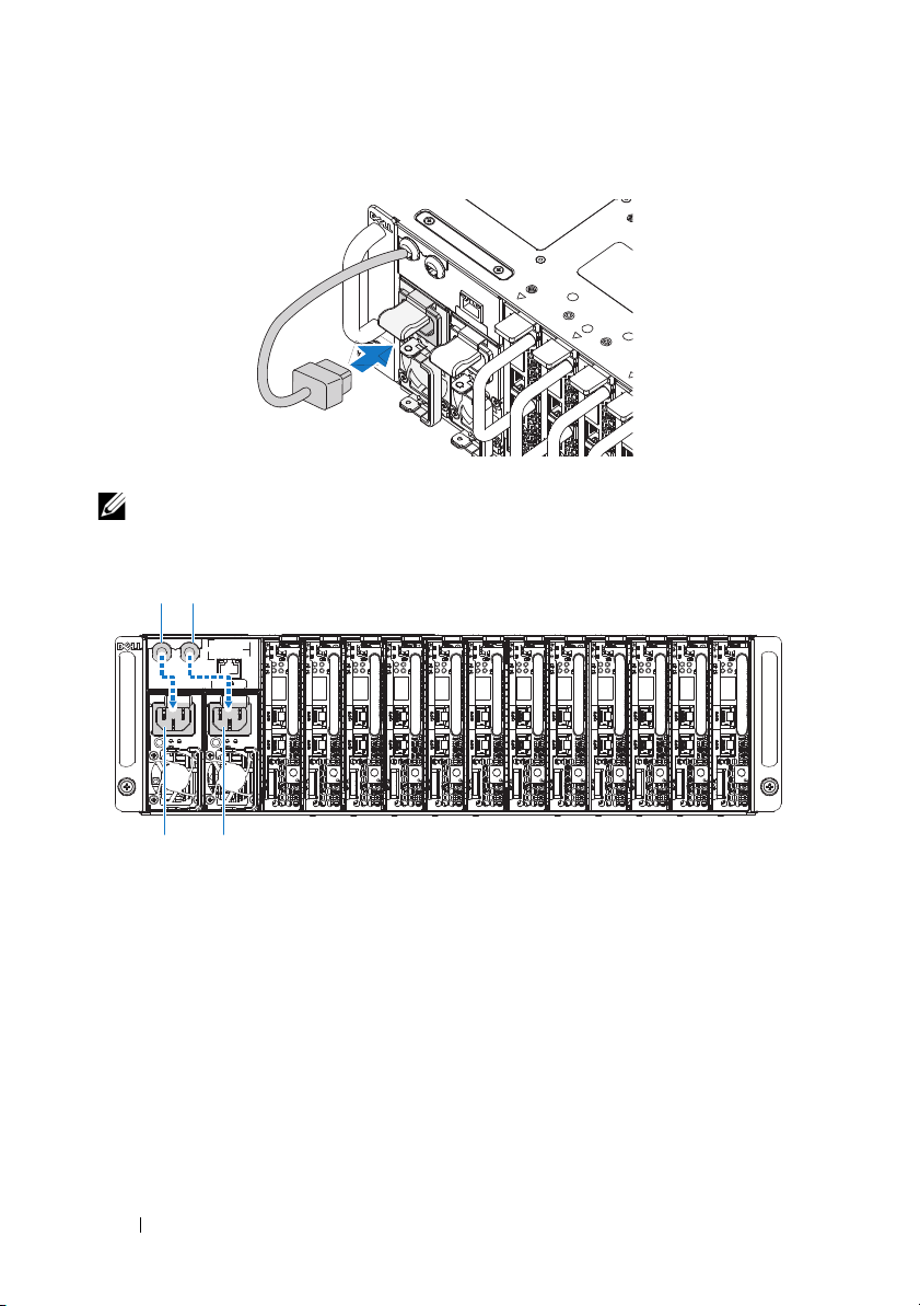
3
PSU1 PSU2
PSU1 PSU2
Plug the chassis power cable into the power supply unit.
NOTE: The correct configuration of the integral chassis AC power cables to the
PSU sockets is as shown in the following illustration.
10 Installation and Configuration
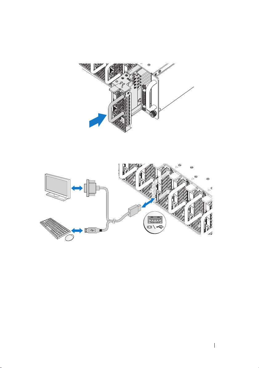
4
Install the sleds. Push the sled into the system until flush with the case and
the release latch locks.
Connecting the Keyboard, Mouse, and Monitor
The connector on the front of your system has an icon indicating which cable
to plug in. Connect a keyboard, mouse, or monitor (optional).
Installation and Configuration 11
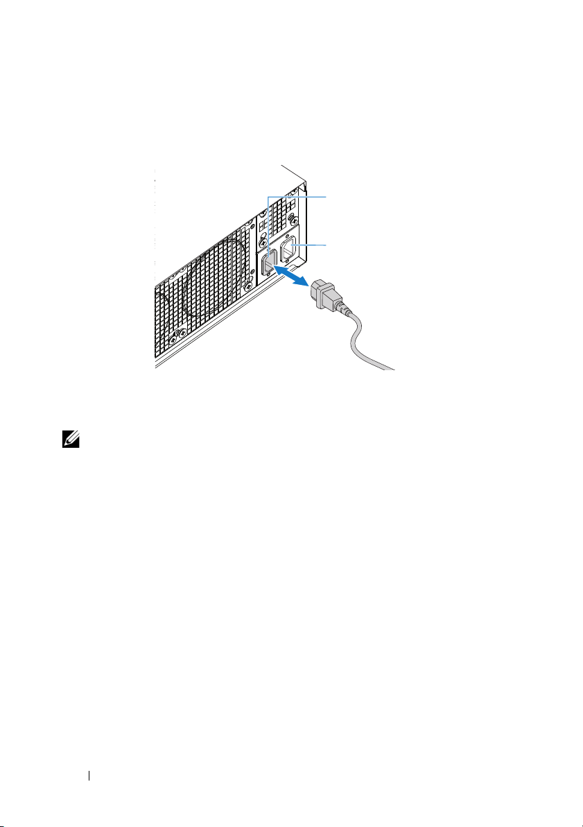
Connecting the Power Cables
AC Port 2
AC Port 1
1
On the back of the system, connect the mains power cable to the system’s
power socket.
2
Plug the other end of the power cables into a grounded electrical outlet or
a separate power source such as an uninterrupted power supply or a power
distribution unit.
NOTE:
AC Port 1 provides power to PSU1, ACP Port 2 provides power to PSU2. See
Populate the System step 3 for further information.
Turning On the System
When connected to a power source the system automatically powers on.
See the Using the Baseboard Management Controller Guide at
support.dell.com/manuals.
12 Installation and Configuration
Complete the Operating System Setup
To install an operating system for the first time, see the installation and
configuration documentation for your operating system. Be sure the
operating system is installed before installing hardware or software not
purchased with the system.
Supported Operating Systems
• Microsoft Windows Server 2008 Enterprise Edition Release 2 (64-bit)
• Microsoft Windows HPC 2008 Release 2
• Microsoft HyperV
• Red Hat Enterprise Linux 6.0 (64-bit)
• SUSE Linux Enterprise Server 11 SP1 (64-bit)
• Citrix XenServer Enterprise Edition 5.6
NOTE:
For the latest information on supported operating systems, see
support.dell.com.
Other Information You May Need
WARNING: See the safety and regulatory information that shipped with your
system. Warranty information may be included within this document or as a
separate document.
See the Hardware Owner’s Manual for information about system features,
troubleshooting, and component replacement. This document is available at
support.dell.com/manuals
See the Using the Baseboard Management Controller Guide at
support.dell.com/manuals.
NOTE: Always check for updates and read the updates first because they often
supersede information in other documents.
.
Installation and Configuration 13

Technical Specifications
Processor (Per System Board)
Processor type AMD Phenom II 910e, 2.6 GHz, 4 core
AMD Athlon II 610E, 2.4 GHz, 4 core
AMD Athlon II 260U, 1.6 GHz, 2 core
Expansion Bus (Per System Board)
Bus type PCI-E x1 connector for sideband signal
Internal PCIe Bus 1, SR5650(GPP3): PCI-E
x2,x1,x1,x1,x1,x4
3, SP5100: PCI 32/33
Memory (Per System Board)
Architecture UDDR3-1333
Memory module sockets 4 Quad Channel Unbuffered DDR3
800/1066/1333
Memory module capacities
Minimum RAM 2 GB
Maximum RAM 16 GB
Drives (Per System Board)
Hard drives SATAII (4 channels) support:
• 3.5" HDD x2 (Max Capacity 2 TB per
drive)
• 2.5" HDD x4 (Max Capacity 500 GB
per drive), SSD
Connectors (Per System Board)
Back
NIC
Serial (internal)
USB (through Y-cable)
Video (through Y-cable)
KVM over IP Port
2
1
2
1
1
14 Technical Specifications

Video
Video type AST2050
Video memory 128 MB DDR2 SDRAM
Power
AC power supply (per power supply)
Wattage
Vo lt ag e
Heat dissipation
Maximum inrush current
Physical
Sled system dimension (with 3.5" HDD)
Standard sled size:
VLP sled size:
Mainboard
Hard drives (3.5")
Hard drive board (3.5")
Sled system dimension (with 2.5" HDD)
Standard sled size:
VLP sled size:
Mainboard
Hard drives (2.5")
Hard drive board (3.5")
1400 W
200-240 VAC, 50/60 Hz, 9.6 A max
47.65 BTU/hr max
55 A max
613.3 mm x 124 mm x 42.45 mm
(8 sled)
613.3 mm x 124 mm x 27.7 mm
(12 sled)
1
2
1
613.3 mm x 124 mm x 42.45 mm
(8 sled)
613.3 mm x 124 mm x 27.7 mm
(12 sled)
1
4
1
Technical Specifications 15

Chassis
Height
Width
Depth
Weight (loaded: maximum weight)
Weig h t (e m pty )
Environmental
13 cm (5.1 in.)
44.7 cm (17.6 in.)
75 cm (29.5 in.)
8 sled configuration:
45 kg (99.21 lbs.)
12 sled configuration:
51.22 kg (112.92 lbs.)
8 sled configuration:
18.3 kg (40.34 lbs.)
12 sled configuration:
19.3 kg (42.55 lbs.)
NOTE: For additional information about environmental measurements for specific
system configurations, see the dell.com/environmental_datasheets.
Temperature
Operating
Airflow at maximum fan speed
(CFM) at peak temperature
Airflow at nominal fan speed (CFM)
at nominal temperature
Storage
Relative Humidity
Operating
Storage
10° to 35°C (50°F to 95°F) with a maximum
temperature gradation of 10°C (per hour
140 CFM (8 sled)
285 CFM (12 sled)
40 CFM (8 sled)
60 CFM (12 sled)
–40° to 65°C (40°F to 149°F) with a
maximum temperature gradation of 20°C
per hour
20% to 80% (noncondensing) with a
maximum humidity gradation of 10%
per hour
5% to 95% (noncondensing)
16 Technical Specifications

Environmental (continued)
Maximum vibration
Operating
Storage
Maximum shock
Operating
Storage
Altitude
Operating
Storage
Airborne Contaminant Level
Class
0.26 Grms at 5–350 Hz
1.87 Grms at 10–500 Hz for 15 min
One shock pulse in the positive z axis (one
pulse on each side of the system) of 31 G for
2.6 ms in the operational orientation
Six consecutively executed shock pulses in
the positive and negative x, y, and z axes
(one pulse on each side of the system) of
71 G for up to 2 ms.
Six consecutively executed shock pulses in
the positive and negative x, y, and z axes
(one pulse on each side of the system) of
22 G faired square wave pulse with velocity
change at 200 inches/second
-16 to 3,048 m (-50 to 10,000 ft.)
NOTE: For altitudes above 2,950 feet, the
maximum operating temperature s derated to
1°F/550 ft.
-16 to 10, 600 m (-50 to 35,000 ft.)
G2 or lower as defined by ISA-S71.04-1985
Technical Specifications 17

18 Technical Specifications

Dell PowerEdge C5125
Začínáme
se systémem
Regulatorní model: B04S
Poznámky a upozornění
POZNÁMKA: POZNÁMKA označuje důležité informace, které uživateli
pomohou v lepším využití počítačového systému.
UPOZORNĚNÍ: UPOZORNĚNÍ poukazuje na možnost poškození
hardwaru nebo ztráty dat v případě nedodržení pokynů.
VAROVÁNÍ: VAROVÁNÍ upozorňuje na potenciální nebezpečí
poškození majetku, úrazu nebo smrti.
____________________
Informace v této publikaci se mohou bez předchozího upozornění změnit.
© 2011 Dell Inc. Všechna práva vyhrazena.
Jakákoli reprodukce těchto materiálů bez písemného povolení společnosti Dell Inc. je přísně zakázána.
™
Ochranné známky použité v tomto textu: Dell
společnosti Dell Inc. AMD
Advanced Micro Devices, Inc. Microsoft
ochranné známky společnosti Microsoft Corporation v USA a dalších zemích. Red Hat
Enterprise Linux
zemích. SUSE™ je ochranná známka společnosti Novell Inc. v USA a dalších zemích. Citrix
a XenServer
Inc. v USA a dalších zemích. VMware
v USA a dalších zemích.
V této publikaci mohou být použity další ochranné známky a obchodní názvy s odkazem na společnosti
vlastnící tyto známky a názvy nebo na jejich produkty. Společnost Dell Inc. nemá vlastnické zájmy
vůči ochranným známkám a obchodním názvům jiným než svým vlastním.
®
®
jsou registrované ochranné známky nebo ochranné známky společnosti Citrix Systems,
®
, AMD Phenom™ a AMD Athlon™ jsou ochranné známky společnosti
jsou registrované ochranné známky společnosti Red Hat, Inc. v USA a dalších
®
, logo DELL a PowerEdge™ jsou ochranné známky
®
a Windows® jsou ochranné známky nebo registrované
je registrovaná ochranná známka společnosti VMware, Inc.
®
a Red Hat
®
, Xen®
Regulatorní model B04S
Březen 2011 Č. dílu R5VKT Rev. A00
UPOZORNĚNÍ: Umístění s omezeným přístupem
Tento server je určen k instalaci pouze na místa s omezeným přístupem, jak jsou
definována v čl. 1.2.7.3 normy IEC 60950-1: 2001, kde platí obě tyto podmínky:
•
Přístup mohou získat pouze servisní pracovníci nebo uživatelé, kteří byli
poučeni o důvodech omezení platného pro umístění a o veškerých
bezpečnostních opatřeních, jež je nutné dodržovat.
•
Přístup je poskytován za použití nástroje nebo zámku a klíče nebo je jinak
zabezpečen a je řízen představitelem zodpovědným za toto umístění.
Instalace a konfigurace
VAROVÁNÍ: Před provedením následujícího postupu si prostudujte
bezpečnostní pokyny dodané se systémem a řiďte se jimi.
Rozbalení systému
Rozbalte systém a identifikujte jeho jednotlivé součásti.
Instalace stojanového řešení s přístupem bez nářadí
VAROVÁNÍ: Při každém zvedání systému požádejte o asistenci.
Systém nezvedejte sami, vyvarujete se tak možného zranění.
VAROVÁNÍ: Systém není připevněn ke stojanu ani ke kolejničkám.
Chcete-li předejít možnosti zranění osob nebo poškození systému,
je třeba systém během instalace a vyjímání dostatečně stabilizovat.
VAROVÁNÍ: Chcete-li předejít nebezpečí úrazu elektrickým proudem,
je nutné při instalaci do stojanu použít třetí bezpečnostní zemnicí
vodič. Stojanové vybavení musí systému poskytovat dostatečný
průchod vzduchu a zajišt’ovat tak dostatečné chlazení.
UPOZORNĚNÍ: Při instalaci kolejniček do stojanu se čtvercovými
otvory je důležité zajistit, aby byl do čtvercových otvorů zasunut
čtyřhranný kolík.
UPOZORNĚNÍ: Pro správnou instalaci je nutné, aby byly čtyřhranné
kolíky zarovnány s otvory na stojanu.
Instalace a konfigurace 21
1
Otevřete západky kolejniček zatažením za uvolňovací knoflíky ve středu
zadních konců kolejniček.
2
Zarovnejte koncovky kolejniček se svislými přírubami stojanu a usaďte
kolíky do dolního otvoru prvního tvaru U a do horního otvoru druhého
tvaru U. Usaďte zadní konec kolejničky tak, aby západka zaklapla na místo.
POZNAMKA: Kolejničky lze použít ve stojanech se čtvercovými i kulatými
otvory.
Back
Front
22 Instalace a konfigurace

3
Nasaďte na stojan jistící knoflík.
4
Zopakováním kroků 1 až 3 usaďte a připevněte ke svislé přírubě přední
konec kolejničky.
POZNAMKA: Chcete-li kolejničky vyjmout, můžete je uvolnit zatažením za
uvolňovací knoflík ve středu zadního konce kolejničky.
Instalace a konfigurace 23
Instalace systému
Vyprázdnění šasi systému
1
Vyjměte ze systému jednotky zdrojů napájení. Odpojte napájecí kabely od
jednotek zdrojů napájení.
.
2
Vytáhněte rukojet’ jednotek zdrojů napájení.
24 Instalace a konfigurace

3
Zatlačte uvolňovací západku směrem dolů .
4
Vytáhněte jednotky zdrojů napájení ze systému .
5
Zatlačte uvolňovací západku směrem dolů . Vytáhněte sáňky ze
systému
.
Instalace a konfigurace 25

Instalace systému do stojanu
VAROVÁNÍ: Při každém zvedání systému požádejte o asistenci.
Systém nezvedejte sami, vyvarujete se tak možného zranění.
1
Zasuňte systém do stojanu.
2
Pokud je namontován stabilizační přepravní držák šasi (volitelný), vyjměte
jej ze stojanu.
POZNAMKA: Chcete-li přepravovat systémy již nainstalované ve stojanu,
zajistěte, aby byly tyto dva stabilizační přepravní držáky šasi (volitelné)
správně namontovány.
3
Pomocí šroubků s roznýtovaným koncem upevněte ouška na systému k
přední části stojanu.
4
Nainstalujte zajišt’ovací svorku na přírubu a připevněte ji pomocí
šroubků M5.
POZNAMKA: Dbejte na to, aby byl správně usazen uvolňovací
mechanismus západky.
26 Instalace a konfigurace
Zaplnění systému
1
Zasuňte jednotky zdrojů napájení do systému, dokud nebudou zarovnány s
šasi a nezaklapne uvolňovací západka.
2
Zavřete rukojet’ jednotek zdrojů napájení.
Instalace a konfigurace 27

3
PSU1 PSU2
PSU1 PSU2
Zapojte napájecí kabely šasi do jednotek zdrojů napájení.
POZNAMKA: Správná konfigurace integrálních napájecích kabelů šasi a
soketů PSU je znázorněna na následující ilustraci.
28 Instalace a konfigurace
 Loading...