

Dell PowerEdge C5125 User Manual [ja]

Dell PowerEdge C5125
Getting Started
With Your System
系统使用入门
Memulai Dengan Sistem Anda
はじめに
시스템 시작 안내서


Dell PowerEdge C5125
Getting Started
With Your System
Regulatory Model: B04S
Notes, Cautions, and Warnings
NOTE: A note indicates important information that will help a user make better use
of a computer system.
CAUTION: A caution indicates potential damage to hardware or loss of data is
instructions are not followed.
WARNING: A WARNING indicates a potential for property damage, personal
injury, or death.
____________________
Information in this publication is subject to change without notice.
© 2011 Dell Inc. All rights reserved.
Reproduction of these materials in any manner whatsoever without the written permission of Dell Inc.
is strictly forbidden.
™
Trademarks used in this text: Dell
®
, AMD Phenom™, and AMD Athlon™ are trademarks of Advanced Micro Devices, Inc.
AMD
Microsoft
in the United States and/or other countries. Red Hat
trademarks of Red Hat, Inc. in the United States and/or other countries. SUSE™ is a trademark of
Novell Inc. in the United States and other countries. Citrix
registered trademarks or trademarks of Citrix Systems, Inc. in the United States and/or other countries.
VMware
countries.
Other trademarks and trade names may be used in this publication to refer to either the entities claiming
the marks and names or their products. Dell Inc. disclaims any proprietary interest in trademarks and
trade names other than its own.
®
and Windows® are either trademarks or registered trademarks of Microsoft Corporation
®
is a registered trademarks or trademarks of VMWare, Inc. in the United States or other
, the DELL logo, and PowerEdge™ are trademarks of Dell Inc.
®
and Red Hat Enterprise Linux® are registered
®
, Xen®, and XenServer® are either
Regulatory Model B04S
March 2011 P/N J07TW Rev. A00
CAUTION: Restricted Access Location
This server is intended for installation only in restricted access locations as
defined in Cl. 1.2.7.3 of IEC 60950-1: 2001 where both these conditions
apply:
• Access can only be gained by service persons or by users who have been
instructed about the reasons for the restrictions applied to the location and
about any precautions that shall be taken.
• Access is through the use of a tool or lock and key, or other means of
security, and is controlled by the authority responsible for the location.
Installation and Configuration
WARNING: Before performing the following procedure, review and follow the
safety instructions that came with the system.
Unpacking the System
Unpack your system and identify each item.
Installing the Tool-Less Rail Solution
WARNING: Whenever you need to lift the system, get others to assist you.
To avoid injury, do not attempt to lift the system by yourself.
WARNING: The system is not fixed to the rack or mounted on the rails. To avoid
personal injury or damage to the system, you must adequately support the system
during installation and removal.
WARNING: To avoid a potential electrical shock hazard, a third wire safety
grounding conductor is necessary for the rack installation. The rack equipment
must provide sufficient airflow to the system to maintain proper cooling.
CAUTION: When installing rails in a square-hole rack it is important to ensure
that the square peg slides through the square holes.
CAUTION: Square studs must be flush with the rack posts to install properly.
Installation and Configuration 3
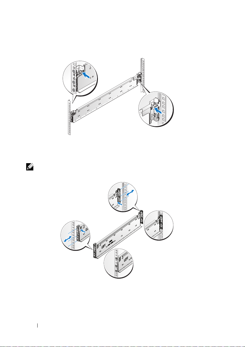
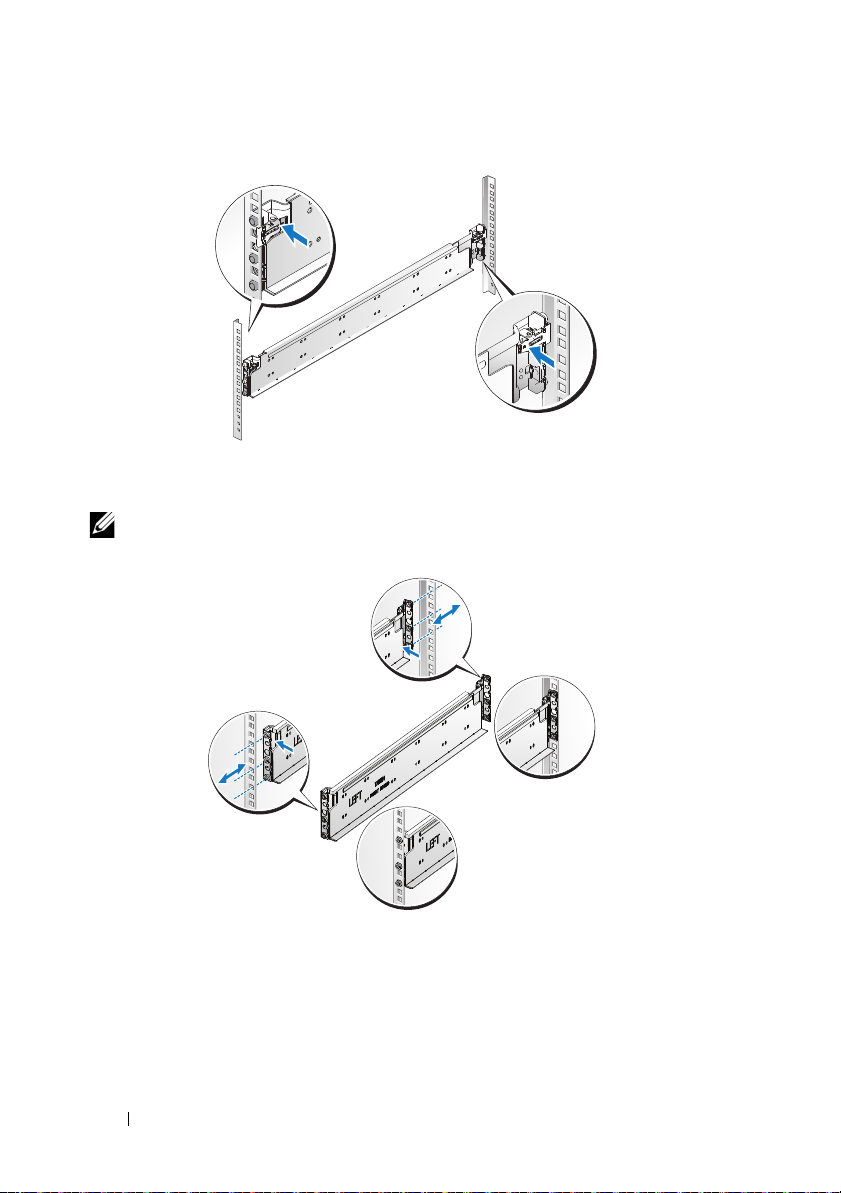
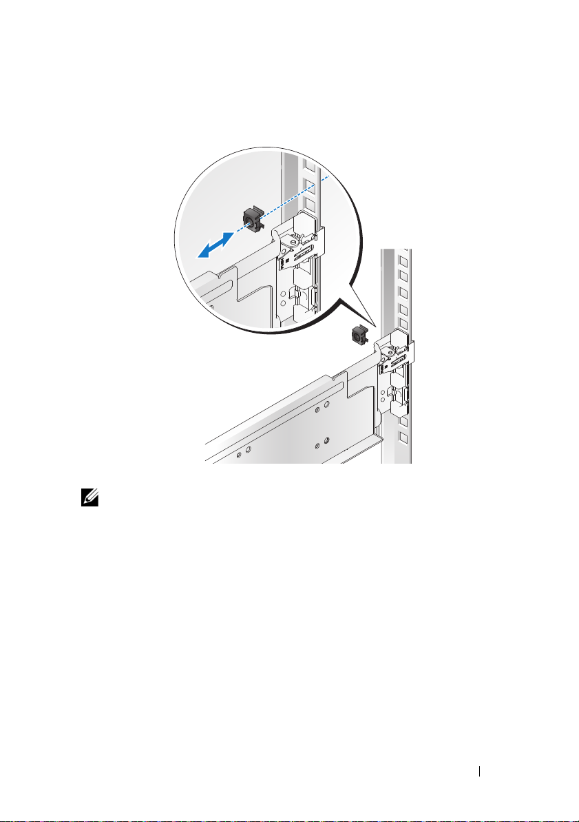
1
Pull on the latch release buttons on the end piece midpoints to open the
rail latches.
2
Align the end pieces of the rails on the vertical rack flanges to seat the pegs
in the bottom hole of the first U and the top hole of the second U. Engage
the back end of the rail until the latch locks in place.
NOTE: The rails can be used in both square-hole and round-hole racks.
Back
Front
4 Installation and Configuration
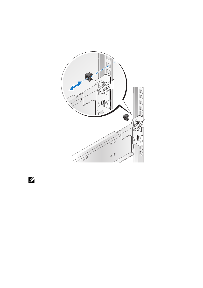
3
Insert the cage nut on the rack.
4
Repeat steps 1 to 4 to position and seat the front end piece on the vertical
flange.
NOTE: To remove the rails, pull on the latch release button on the end piece
midpoint and unseat each rail.
Installation and Configuration 5
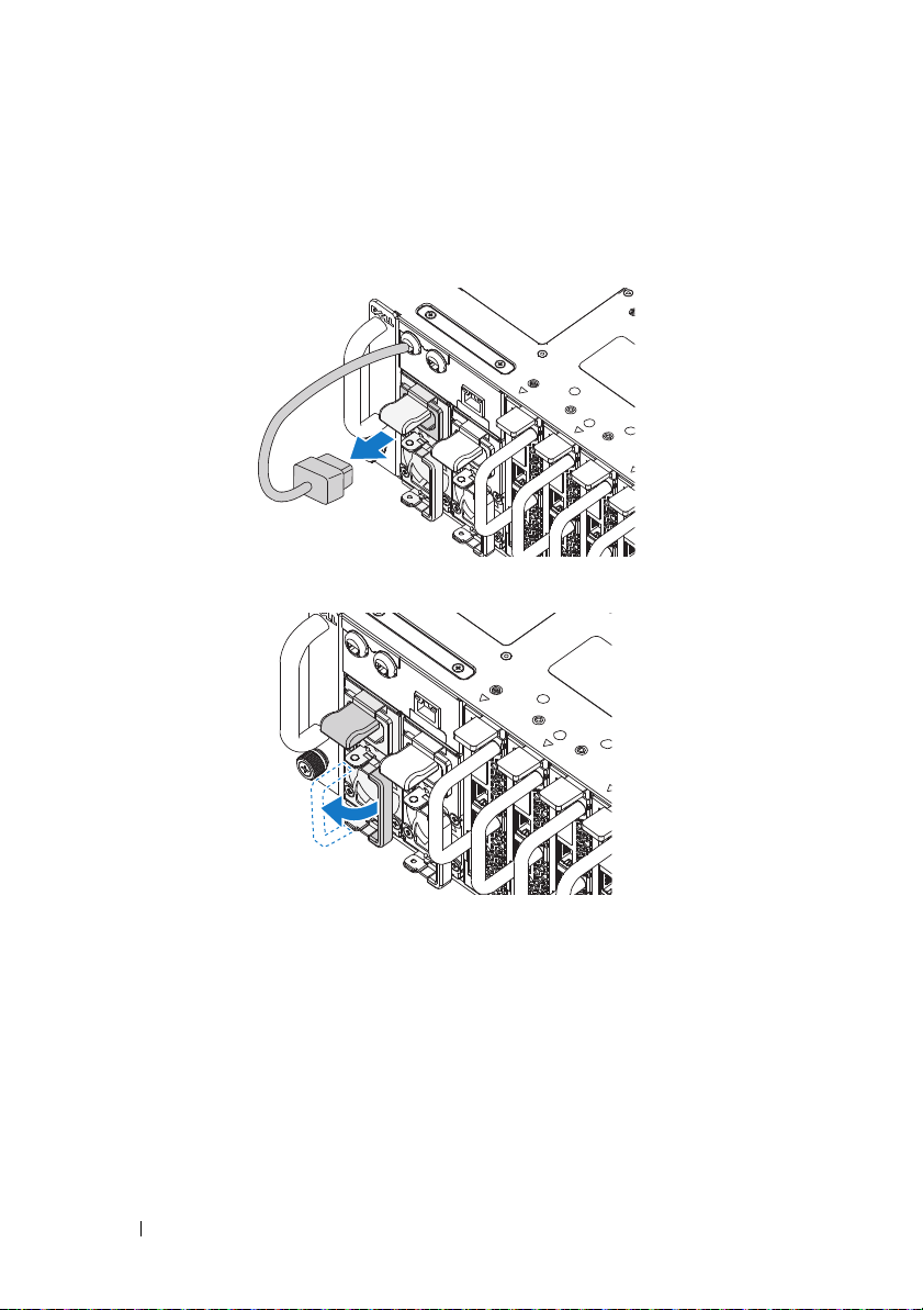
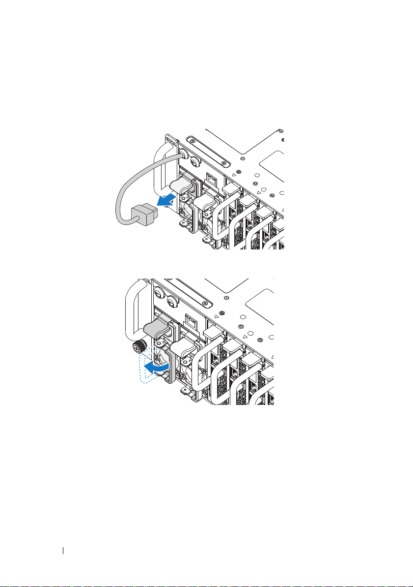
Installing the System
Empty the System Chassis
1
Unplug the power cable from the power supply unit.
.
2
Pull out the power supply unit handle.
6 Installation and Configuration

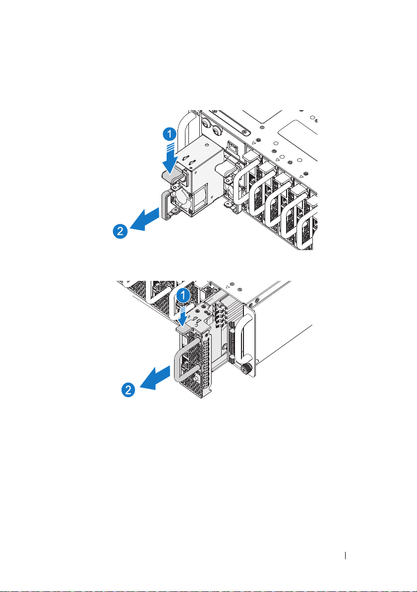
3
Press down on the release latch .
4
Pull the power supply unit out of the system .
5
Press the release latch down and pull the sled out of the system .
Installation and Configuration 7
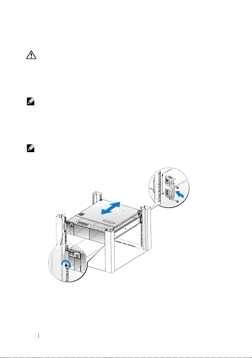
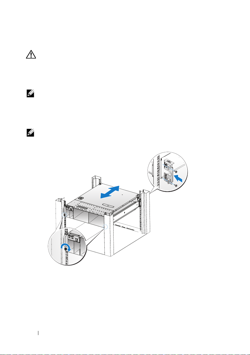
Install the System Into the Rack
WARNING: Whenever you need to lift the system, get others to assist you.
To avoid injury, do not attempt to lift the system by yourself.
1
Slide the system into the rack.
2
If present, remove the chassis stabilizer shipping bracket (optional) from
the rack.
NOTE: To transport systems already installed in the rack, ensure that the two
chassis stabilizer shipping brackets (optional) are in place.
3
Tighten the captive thumbscrews to secure the ears of the system to the
front of the rack.
4
Install the stopping bracket on the post and secure with M5 screws.
NOTE: Make sure the latch release mechanism is engaged correctly.
8 Installation and Configuration
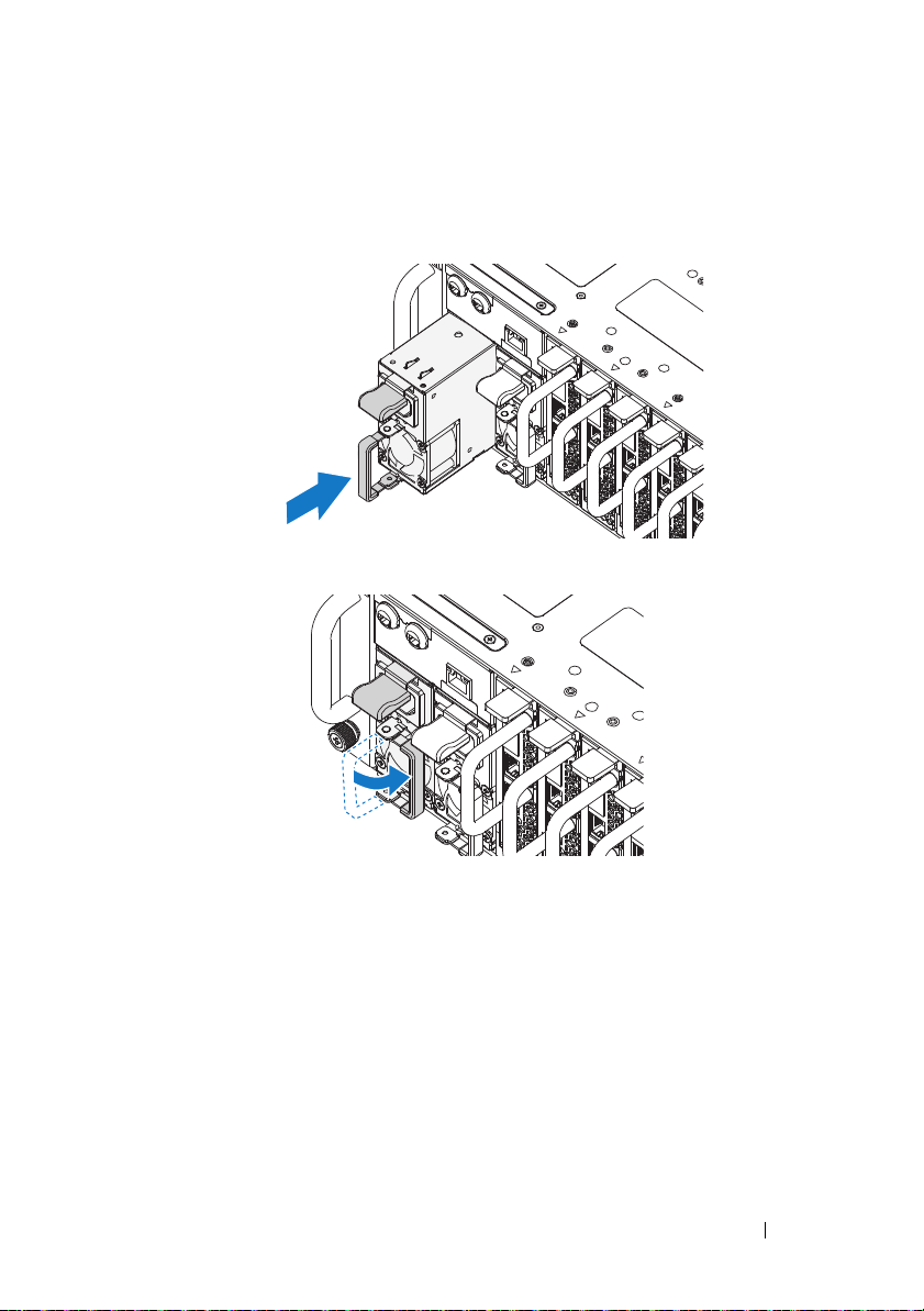
Populate the System
1
Push the power supply unit into the system until flush with the case and
the release latch locks.
2
Close the power supply unit handle.
Installation and Configuration 9
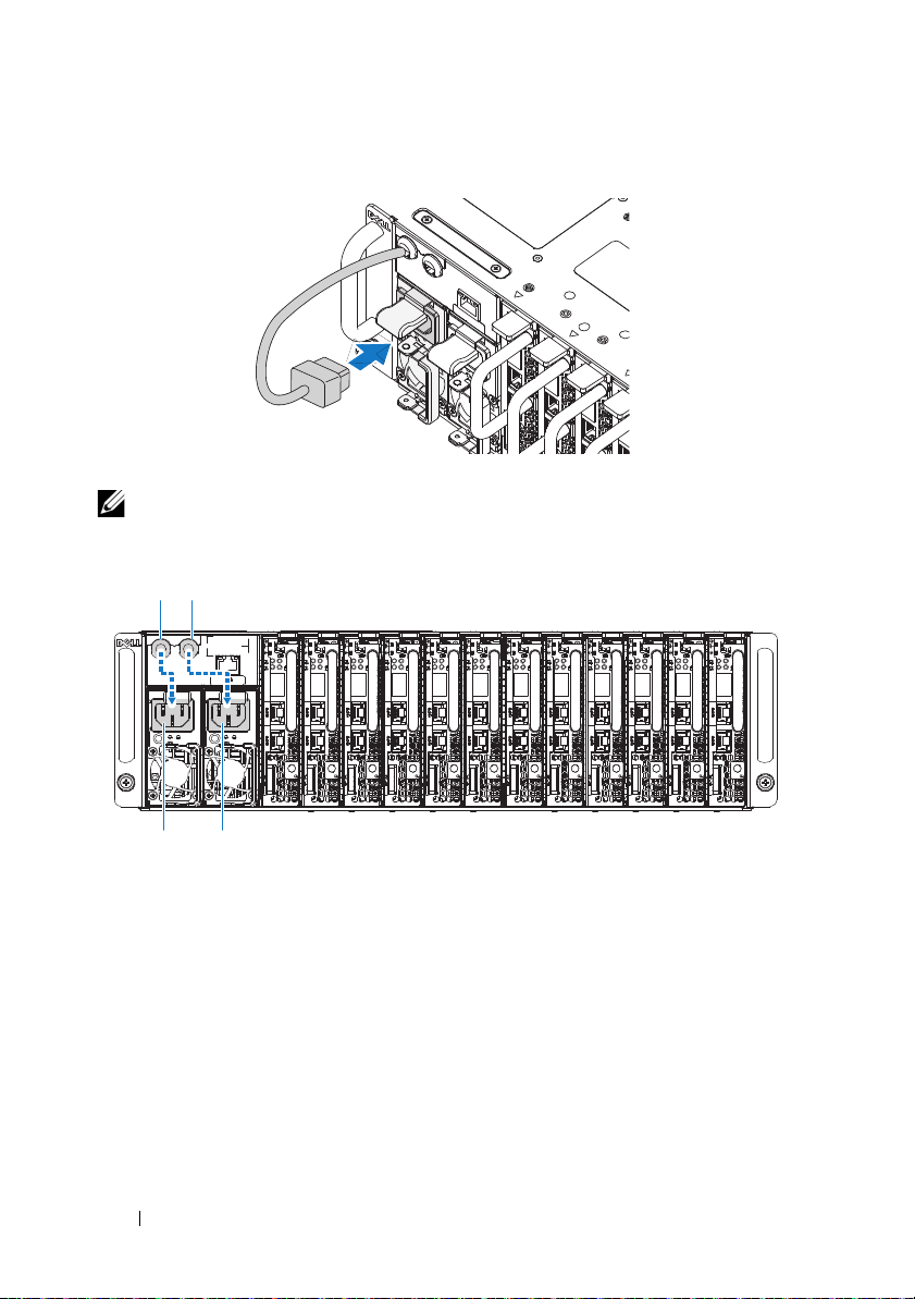
3
PSU1 PSU2
PSU1 PSU2
Plug the chassis power cable into the power supply unit.
NOTE: The correct configuration of the integral chassis AC power cables to the
PSU sockets is as shown in the following illustration.
10 Installation and Configuration
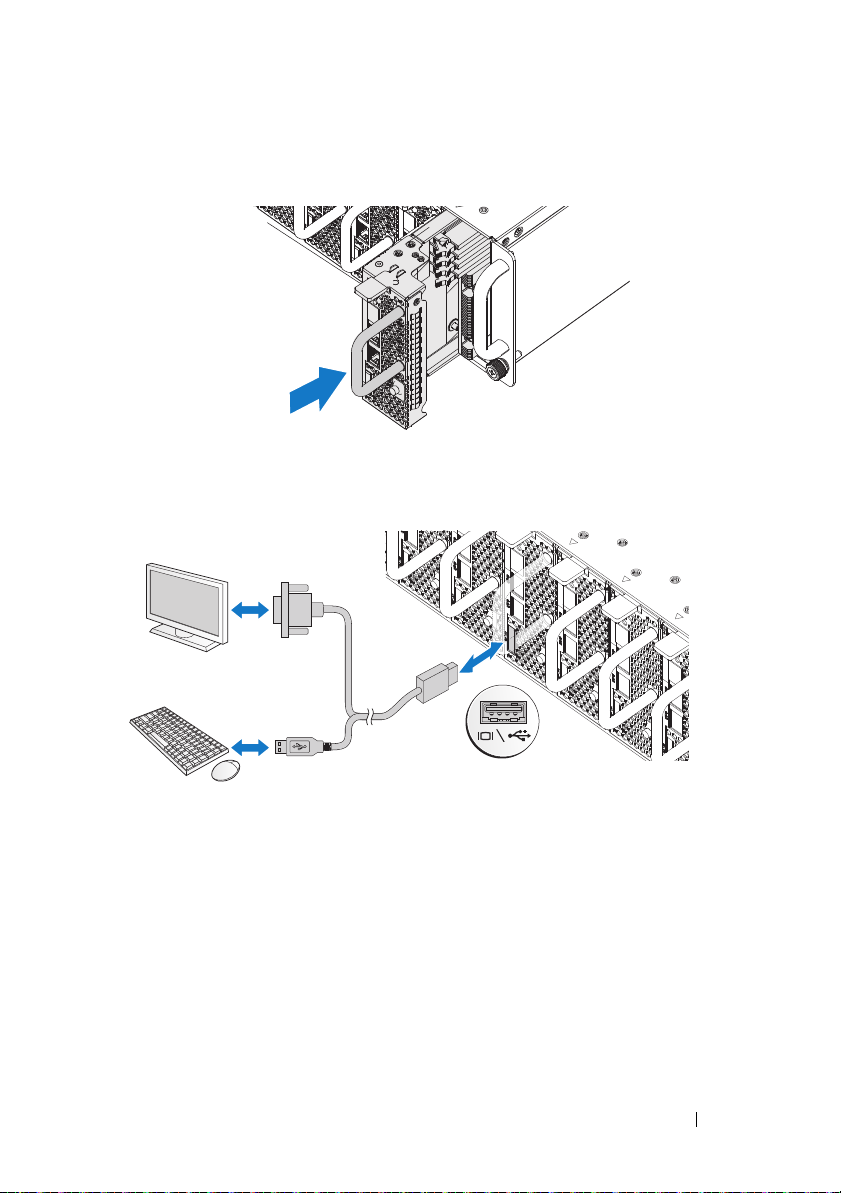
4
Install the sleds. Push the sled into the system until flush with the case and
the release latch locks.
Connecting the Keyboard, Mouse, and Monitor
The connector on the front of your system has an icon indicating which cable
to plug in. Connect a keyboard, mouse, or monitor (optional).
Installation and Configuration 11
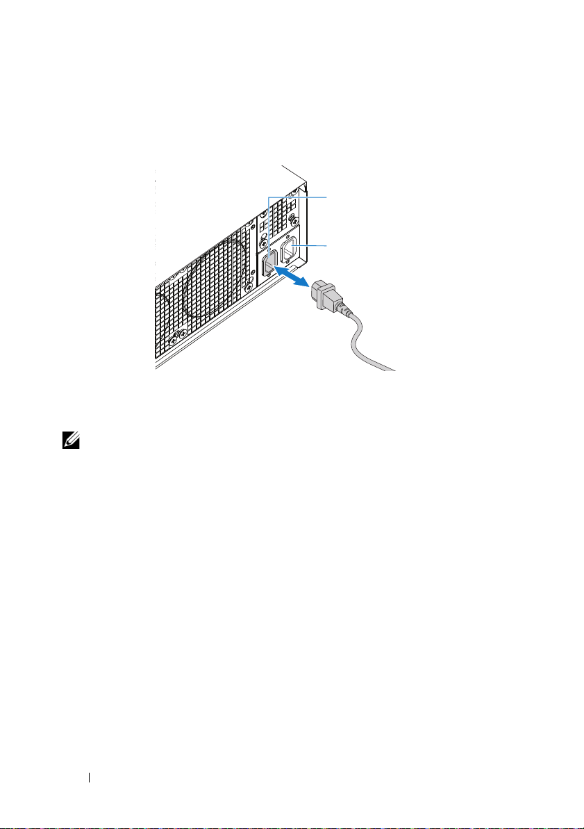
Connecting the Power Cables
AC Port 2
AC Port 1
1
On the back of the system, connect the mains power cable to the system’s
power socket.
2
Plug the other end of the power cables into a grounded electrical outlet or
a separate power source such as an uninterrupted power supply or a power
distribution unit.
NOTE: AC Port 1 provides power to PSU1, ACP Port 2 provides power to PSU2. See
Populate the System step 3 for further information.
12 Installation and Configuration

Turning On the System
When connected to a power source the system automatically powers on.
See the Using the Baseboard Management Controller Guide at
support.dell.com/manuals.
Complete the Operating System Setup
To install an operating system for the first time, see the installation and
configuration documentation for your operating system. Be sure the
operating system is installed before installing hardware or software not
purchased with the system.
Supported Operating Systems
• Microsoft Windows Server 2008 Enterprise Edition Release 2 (64-bit)
• Microsoft Windows HPC 2008 Release 2
• Microsoft HyperV
• Red Hat Enterprise Linux 6.0 (64-bit)
• SUSE Linux Enterprise Server 11 SP1 (64-bit)
• Citrix XenServer Enterprise Edition 5.6
NOTE: For the latest information on supported operating systems, see
support.dell.com.
Installation and Configuration 13

Other Information You May Need
WARNING:
system. Warranty information may be included within this document or as a
separate document.
See the Hardware Owner’s Manual for information about system features,
troubleshooting, and component replacement. This document is available at
support.dell.com/manuals
See the Using the Baseboard Management Controller Guide at
support.dell.com/manuals.
NOTE: Always check for updates and read the updates first because they often
supersede information in other documents.
See the safety and regulatory information that shipped with your
.
Información de la NOM (sólo para México)
La información que se proporciona a continuación aparece en el dispositivo
descrito en este documento, en cumplimiento de los requisitos de la Norma
Oficial Mexicana (NOM):
Importador Dell Inc. de México, S.A. de C.V.
Paseo de la Reforma 2620 – 11° Piso
Col. Lomas Altas
11950 México, D.F.
Número de modelo B04S
Voltaje de alimentación 200-240 V CA
Frecuencia 50/60 Hz
Consumo eléctrico 9 A para cada entrada de alimentación
14 Installation and Configuration

Technical Specifications
Processor (Per System Board)
Processor type AMD Phenom II 910e, 2.6 GHz, 4 core
AMD Athlon II 610E, 2.4 GHz, 4 core
AMD Athlon II 260U, 1.6 GHz, 2 core
Expansion Bus (Per System Board)
Bus type PCI-E x1 connector for sideband signal
Internal PCIe Bus 1, SR5650(GPP3): PCI-E
x2,x1,x1,x1,x1,x4
3, SP5100: PCI 32/33
Memory (Per System Board)
Architecture UDDR3-1333
Memory module sockets 4 Quad Channel Unbuffered DDR3
800/1066/1333
Memory module capacities
Minimum RAM 2 GB
Maximum RAM 16 GB
Drives (Per System Board)
Hard drives SATAII (4 channels) support:
• 3.5" HDD x2 (Max Capacity 2 TB per
drive)
• 2.5" HDD x4 (Max Capacity 500 GB
per drive), SSD
Connectors (Per System Board)
Back
NIC
Serial (internal)
USB (through Y-cable)
Video (through Y-cable)
KVM over IP Port
2
1
2
1
1
Technical Specifications 15

Video
Video type AST2050
Video memory 128 MB DDR2 SDRAM
Power
AC power supply (per power supply)
Wa t ta g e
Vo lt ag e
Heat dissipation
Maximum inrush current
Physical
Sled system dimension (with 3.5" HDD)
Standard sled size:
VLP sled size:
Mainboard
Hard drives (3.5")
Hard drive board (3.5")
Sled system dimension (with 2.5" HDD)
Standard sled size:
VLP sled size:
Mainboard
Hard drives (2.5")
Hard drive board (3.5")
1400 W
200-240 VAC, 50/60 Hz, 9.6 A max
47.65 BTU/hr max
55 A max
613.3 mm x 124 mm x 42.45 mm
(8 sled)
613.3 mm x 124 mm x 27.7 mm
(12 sled)
1
2
1
613.3 mm x 124 mm x 42.45 mm
(8 sled)
613.3 mm x 124 mm x 27.7 mm
(12 sled)
1
4
1
16 Technical Specifications

Chassis
Height
Width
Depth
Weight (loaded: maximum weight)
Weight (empty)
Environmental
13 cm (5.1 in.)
44.7 cm (17.6 in.)
75 cm (29.5 in.)
8 sled configuration:
45 kg (99.21 lbs.)
12 sled configuration:
51.22 kg (112.92 lbs.)
8 sled configuration:
18.3 kg (40.34 lbs.)
12 sled configuration:
19.3 kg (42.55 lbs.)
NOTE: For additional information about environmental measurements for specific
system configurations, see the dell.com/environmental_datasheets.
Temperature
Operating
Airflow at maximum fan speed
(CFM) at peak temperature
Airflow at nominal fan speed (CFM)
at nominal temperature
Storage
Relative Humidity
Operating
Storage
10° to 35°C (50°F to 95°F) with a maximum
temperature gradation of 10°C (per hour)
140 CFM (8 sled)
285 CFM (12 sled)
40 CFM (8 sled)
60 CFM (12 sled)
–40° to 65°C (40°F to 149°F) with a
maximum temperature gradation of 20°C
per hour
20% to 80% (noncondensing) with a
maximum humidity gradation of 10%
per hour
5% to 95% (noncondensing)
Technical Specifications 17

Environmental (continued)
Maximum vibration
Operating
Storage
Maximum shock
Operating
Storage
Altitude
Operating
Storage
Airborne Contaminant Level
Class
0.26 Grms at 5–350 Hz
1.87 Grms at 10–500 Hz for 15 min
One shock pulse in the positive z axis (one
pulse on each side of the system) of 31 G for
2.6 ms in the operational orientation
Six consecutively executed shock pulses in
the positive and negative x, y, and z axes
(one pulse on each side of the system) of
71 G for up to 2 ms.
Six consecutively executed shock pulses in
the positive and negative x, y, and z axes
(one pulse on each side of the system) of
22 G faired square wave pulse with velocity
change at 200 inches/second
-16 to 3,048 m (-50 to 10,000 ft.)
NOTE: For altitudes above 2,950 feet, the
maximum operating temperature s derated to
1°F/550 ft.
-16 to 10, 600 m (-50 to 35,000 ft.)
G2 or lower as defined by ISA-S71.04-1985
18 Technical Specifications

Dell PowerEdge C5125
系统 使用入门
管制型号:
B04S

注、小心和警告
注:
“注”表示可以帮助您更好地使用计算机系统的重要信息。
小心:“小心”表示如果不遵循说明,就有可能损坏硬件或导致数据丢失。
警告:
“警告”表示可能会造成财产损失、人身伤害甚至死亡。
____________________
本出版物中的信息如有更改,恕不另行通知。
© 2011 Dell Inc.
未经
Dell Inc.
本文中使用的商标:
AMD Phenom
Windows
®
Red Hat
商标。
SUSE
是
Citrix Systems, Inc.
VMWare, Inc.
本出版物中可能使用到的其它商标和商品名称是指拥有相应标记和名称的公司或其制造的
产品。
Dell Inc.
版权所有,翻印必究。
书面许可,严禁以任何形式复制这些材料。
™
、
Dell
™
和 AMD Athlon™ 是 Advanced Micro Devices, Inc.
®
是
Microsoft Corporation
和 Red Hat Enterprise Linux® 是 Red Hat, Inc.
®
是 Novell Inc.
在美国和/或其它国家/地区的注册商标或商标。
在美国或其它国家/地区的注册商标或商标。
对其它公司的商标和产品名称不拥有任何专有权。
徽标和
DELL
在美国和其它国家/地区的商标。
PowerEdge
在美国和/或其它国家/地区的商标或注册商标。
™
是 Dell Inc.
在美国和/或其它国家/地区的注册
的商标。
Citrix
的商标。
®
、
Xen
VMware
AMD
Microsoft
®
、
XenServer
®
是
®
、
®
和
®
管制型号
2011 年 3 月 P/N J07TW Rev. A00
B04S
小心:受限访问位置
此服务器仅用于安装在由
个条件的受限访问位置中:
•
仅维修人员或对该位置施加限制的理由以及应当采取的防备措施已完
全领会的用户,可对此服务器进行访问。
•
通过同时使用工具或锁和钥匙,或其他安全手段来访问,并且是由位
置的可靠授权来控制的。
IEC 60950-1: 2001 的 Cl. 1.2.7.3
定义的满足下列两
安装和配置
警告:
打开系统包装
打开系统包装并检查各个组件。
安装免工具拆装导轨解决方案
警告:
系统。
警告:
损坏,在安装和拆卸时,必须给系统提供足够的支撑。
警告:
机架设备必须对系统提供足够的通风以维持适当冷却。
执行下列步骤之前,请阅读并遵循系统随附的安全说明。
如需抬高系统时,请让别人帮您。为避免受伤,请勿尝试独自提起
系统未固定到机架上或未安装在导轨上。为避免人身伤害或系统
为避免可能的电击伤害,机架安装需要第三根导线安全接地连接器。
小心:在方孔机架中安装导轨时,务必确保方形插销穿过方孔。
小心:方形螺栓必须与机架柱对齐以正确安装。
安装和配置 21
1
拔起尾段正中央的闩锁释放按钮以打开导轨闩锁。
2
在机架垂直凸缘上对齐导轨的尾段,将插销放在第一个
第二个
注:
的顶孔中。使导轨后端咬合,直到闩锁锁到位。
U
导轨可以在方孔和圆孔机架中使用。
Back
Front
的底孔中和
U
22 安装和配置
3
将锁紧螺帽插入机架。
4
重复步骤
注:
1 至4
要卸下导轨,请拔起尾段正中央的闩锁释放按钮并取出每个导轨。
,在垂直凸缘上放置和固定前端部分。
安装和配置 23
安装系统
清空系统机箱
1
拔下电源设备的电源电缆。
2
拉出电源设备手柄。
24 安装和配置
3
按下释放闩锁
4
拉出系统中的电源设备
5
按下释放闩锁 并拉出系统中的底座
。
。
。
安装和配置 25
将系统安装到机架中
警告:
系统。
1
将系统滑入到机架中。
2
如果存在运输时稳固机箱的支架 (可选),请将其从机架上卸下。
注:
到位 (可选)。
3
拧紧系留指旋螺钉,将系统吊耳固定到机架正面。
4
在柱上安装定位支架并使用
注:
如需抬高系统时,请让别人帮您。为避免受伤,请勿尝试独自提起
要运输已经安装在机架上的系统,请确保两个运输时稳固机箱的支架
螺钉固定。
M5
确保闩锁释放装置正确啮合。
26 安装和配置
 Loading...