

Dell PowerEdge C1100 User Manual

Dell™ PowerEdge™ C1100
Systems
Hardware Owner’s
Manual
Regulatory Model CS24-TY

Notes, Cautions, and Warnings
NOTE: A NOTE indicates important information that helps you make better use of
your computer.
CAUTION: A CAUTION indicates potential damage to hardware or loss of data if
instructions are not followed.
WARNING: A WARNING indicates a potential for property damage, personal
injury, or death.
____________________
© 2013 Dell Inc. All rights reserved.
Trademarks used in this text: Dell™ and the DELL logo are trademarks of Dell Inc.
Regulatory Model CS24-TY
2013 - 02 Rev. A01


Contents
1 About Your System. . . . . . . . . . . . . . . . . . 13
Accessing System Features During Startup. . . . . . . 13
Front-Panel Features and Indicators
. . . . . . . . . . 14
Hard-Drive Indicator Patterns . . . . . . . . . . . . . . 18
Back-Panel Features and Indicators
NIC Indicator Codes
. . . . . . . . . . . . . . . . . . . 20
. . . . . . . . . . 19
Power and System Board Indicator Codes . . . . . . . 21
POST Error Codes
Beep Codes
Post Beep Codes
. . . . . . . . . . . . . . . . . . . . 23
. . . . . . . . . . . . . . . . . . . . . . . 33
. . . . . . . . . . . . . . . . . . . . . 34
Other Information You May Need . . . . . . . . . . . . 34
2 Using the System Setup Program . . . . . . 35
Start Menu . . . . . . . . . . . . . . . . . . . . . . . . 35
System Setup Options at Boot
Console Redirection
. . . . . . . . . . . . . . . . . . . 36
. . . . . . . . . . . . . . 36
Main Menu
Main Screen
AMIBIOS Settings
. . . . . . . . . . . . . . . . . . . . . . . . 37
. . . . . . . . . . . . . . . . . . . . 37
. . . . . . . . . . . . . . . . . 37
Contents 5

Processor Settings . . . . . . . . . . . . . . . . . 38
System Memory Settings . . . . . . . . . . . . . . 38
Advanced Menu . . . . . . . . . . . . . . . . . . . . . 38
Processor Configuration
. . . . . . . . . . . . . . 38
Memory Configuration . . . . . . . . . . . . . . . 40
IDE Configuration
Super IO Configuration
. . . . . . . . . . . . . . . . . . 40
. . . . . . . . . . . . . . . 41
USB Configuration . . . . . . . . . . . . . . . . . 41
PCI Configuration
. . . . . . . . . . . . . . . . . . 41
Boot Menu
. . . . . . . . . . . . . . . . . . . . . . . . 43
Boot Settings Configuration
. . . . . . . . . . . . 43
Server Menu . . . . . . . . . . . . . . . . . . . . . . . 44
BMC LAN Configuration
. . . . . . . . . . . . . . 45
Remote Access Configuration . . . . . . . . . . . 46
Security Menu . . . . . . . . . . . . . . . . . . . . . . 47
Exit Menu
. . . . . . . . . . . . . . . . . . . . . . . . . 47
3 Installing System Components . . . . . . . 49
Safety Instructions . . . . . . . . . . . . . . . . . . . . 49
Recommended Tools
Inside the System. . . . . . . . . . . . . . . . . . . . . 50
Hard Drives
. . . . . . . . . . . . . . . . . . . . . . . . 51
Removing a Hard-Drive Blank
Installing a Hard-Drive Blank
Removing a Hard Drive From a Hard-Drive
. . . . . . . . . . . . . . . . . . . . . . . . 52
Carrier
. . . . . . . . . . . . . . . . . . . 49
. . . . . . . . . . . 51
. . . . . . . . . . . . 52
6 Contents

Installing a Hard Drive Into a Hard-Drive
. . . . . . . . . . . . . . . . . . . . . . . 53
Carrier
Removing a Hard-Drive Carrier
Installing a Hard-Drive Carrier
. . . . . . . . . . . 54
. . . . . . . . . . . 54
Opening and Closing the System
Opening the System
Closing the System
Cooling Shroud
. . . . . . . . . . . . . . . . . 56
. . . . . . . . . . . . . . . . . . . . . . 56
Removing the Cooling Shroud
Installing the Cooling Shroud
Heat Sinks
. . . . . . . . . . . . . . . . . . . . . . . . 58
Removing the Heat Sink
Installing the Heat Sink
Processor
. . . . . . . . . . . . . . . . . . . . . . . . 60
Removing the Processor
Installing the Processor
System Memory
. . . . . . . . . . . . . . . . . . . . . 63
. . . . . . . . . . . . 55
. . . . . . . . . . . . . . . . 55
. . . . . . . . . . . 56
. . . . . . . . . . . . 57
. . . . . . . . . . . . . . 58
. . . . . . . . . . . . . . . 59
. . . . . . . . . . . . . . 60
. . . . . . . . . . . . . . 61
General Memory Module Installation
Guidelines
Mode-Specific Guidelines
. . . . . . . . . . . . . . . . . . . . . . 63
. . . . . . . . . . . . . 64
Memory Socket Location on the System Board
Supported Memory Configuration . . . . . . . . . 66
Removing Memory Modules
Installing Memory Modules
. . . . . . . . . . . . 67
. . . . . . . . . . . . 68
. . 65
Expansion-Card Riser and Expansion Card
Removing the Expansion-Card Riser
Installing the Expansion-Card Riser
Removing the Expansion Card
Installing the Expansion Card
. . . . . . . . . . . 71
. . . . . . . . . . . 72
. . . . . . . 69
. . . . . . . . 69
. . . . . . . . 70
Contents 7

RAID Battery (Optional) . . . . . . . . . . . . . . . . . 73
Removing a RAID Battery
. . . . . . . . . . . . . . 73
Installing a RAID Battery . . . . . . . . . . . . . . 73
Integrated Storage Controller Cards. . . . . . . . . . . 75
Removing the Integrated
Storage Controller Card
. . . . . . . . . . . . . . . 75
Installing the Integrated
Storage Controller Card
. . . . . . . . . . . . . . . 76
Mezzanine Card (10 GbE LAN)
. . . . . . . . . . . . . . 77
Removing the Mezzanine Card (10 GbE LAN)
Installing the Mezzanine Card (10 GbE LAN)
Power Supplies
. . . . . . . . . . . . . . . . . . . . . 80
Removing the Non-Redundant Power Supply
Installing the Non-Redundant Power Supply
Removing the Redundant Power Supply . . . . . . 82
Installing the Redundant Power Supply
Power Distribution Board
. . . . . . . . . . . . . . . . 83
Removing the Power Distribution Board
Installing the Power Distribution Board
Cooling Fans
. . . . . . . . . . . . . . . . . . . . . . . 85
Removing a Cooling Fan Assembly
Installing the Cooling Fan Assembly
Expander Board
. . . . . . . . . . . . . . . . . . . . . 87
Removing the Expander Board
Installing the Expander Board
Backplane
. . . . . . . . . . . . . . . . . . . . . . . . 89
Removing the Backplane
Installing the Backplane
. . . . . . . . . . . . . . 89
. . . . . . . . . . . . . . 91
. . . . . . . . . . . 89
. . . . . . 83
. . . . . . 83
. . . . . . 84
. . . . . . . . . 85
. . . . . . . . 86
. . . . . . . . . . . 87
. . . . 77
. . . . 79
. . . 80
. . . . 81
8 Contents

Control Panel (Optional) . . . . . . . . . . . . . . . . . 91
Removing the Control Panel
. . . . . . . . . . . . 91
Installing the Control Panel. . . . . . . . . . . . . 92
Control Panel Assembly (Optional) . . . . . . . . . . . 92
Removing the Control Panel Assembly
. . . . . . . 92
Installing the Control Panel Assembly . . . . . . . 93
System Battery . . . . . . . . . . . . . . . . . . . . . . 94
Removing the System Battery
. . . . . . . . . . . 94
Installing the System Battery . . . . . . . . . . . . 95
System Board . . . . . . . . . . . . . . . . . . . . . . 96
Removing the System Board
. . . . . . . . . . . . 96
Installing the System Board . . . . . . . . . . . . 97
4 Troubleshooting Your System . . . . . . . . . 99
Safety First—For You and Your System . . . . . . . . . 99
Installation Problems
. . . . . . . . . . . . . . . . . . 99
Troubleshooting System Startup Failure
Troubleshooting External Connections
Troubleshooting the Video Subsystem
Troubleshooting a USB Device
Troubleshooting a Serial I/O Device
Troubleshooting a NIC
Troubleshooting a Wet System
Troubleshooting a Damaged System
. . . . . . . . . . . . . 100
. . . . . . . . . . 101
. . . . . . . . . . . . . . . . . . 102
. . . . . . . . . . . . . 103
. . . . . . . . . . 104
. . . . . . . . 100
. . . . . . . . . 100
. . . . . . . . . 100
Contents 9

Troubleshooting the System Battery . . . . . . . . . . 104
Troubleshooting Power Supplies
Troubleshooting System Cooling Problems
. . . . . . . . . . . 105
. . . . . . 106
Troubleshooting a Fan . . . . . . . . . . . . . . . . . 106
Troubleshooting System Memory
Troubleshooting a Hard Drive
. . . . . . . . . . . 107
. . . . . . . . . . . . . 109
Troubleshooting a Storage Controller . . . . . . . . . 110
Troubleshooting Expansion Cards
Troubleshooting Processors
. . . . . . . . . . . 111
. . . . . . . . . . . . . . 112
IRQ Assignment Conflicts . . . . . . . . . . . . . . . 113
Troubleshooting Changes in BIOS Settings
Collecting System Event Log for Investigation
. . . . . . 114
. . . . 114
5 Jumpers and Connectors. . . . . . . . . . . . 115
System Board Connectors . . . . . . . . . . . . . . . 115
10 Contents
Jumper Settings
. . . . . . . . . . . . . . . . . . . . 116
System Configuration Jumper Settings
Backplane Jumper Settings
Backplane Connectors
3.5-Inch Hard Drives
2.5-Inch Hard Drives
Power Distribution Board
. . . . . . . . . . . . . . 118
. . . . . . . . . . . . . . . . . 119
. . . . . . . . . . . . . . . 119
. . . . . . . . . . . . . . . 120
. . . . . . . . . . . . . . . 122
. . . . . . 116

6 Getting Help. . . . . . . . . . . . . . . . . . . . . . 123
Contacting Dell . . . . . . . . . . . . . . . . . . . . . 123
Glossary . . . . . . . . . . . . . . . . . . . . . . . . . . . . 125
Index . . . . . . . . . . . . . . . . . . . . . . . . . . . . . . 135
Contents 11

12 Contents

1
About Your System
Accessing System Features During Startup
The following keystrokes provide access to system features during startup.
Keystroke Description
<F2> Enters the System Setup program. See "Start Menu" on page 35.
<F11> Enters the BIOS Boot Manager. See "System Setup Options at Boot"
on page 36.
<F12> Starts Preboot eXecution Environment (PXE) boot.
<Ctrl><C> Enters the SAS Configuration Utility. For more information,
see the SAS adapter documentation.
<Ctrl><R> Enters the RAID configuration utility. For more information,
see the documentation for your SAS RAID card.
<Ctrl><S> Enters the utility to configure NIC settings for PXE boot. For more
information, see the documentation for your integrated NIC.
About Your System 13
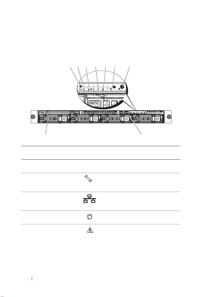
Front-Panel Features and Indicators
9
8
1
2
3
4
5
6
7
Figure 1-1. Front-Panel Features—3.5-Inch Hard-Drive System
Item Indicator, Button,
or Connector
1 Reset button Restarts the system while the system is
2 Service LED Lights when the BMC port is on and
3 Ethernet connectors 1
and 2
4 Hard drive activity
LED
5 Fault LED Displays status/errors and is controlled
Icon Description
powered on.
blinks when there is traffic on the
BMC port.
Lights green when a connection is made
to the NIC port, blinks when there is
traffic on the NIC port.
Lights when the hard drives are active.
by BMC.
14 About Your System
Item Indicator, Button,
or Connector
6 System identification
indicator/button
7Power-on
indicator/power
button
Icon Description
The system identification button can
be used to locate a particular system
and system board within a rack.
When the button is pushed, the blue
system status indicators on the front
and the back blink until the button
is pushed again.
The power-on indicator lights
when the system power is on.
The power button controls the
DC power supply output to the system.
NOTE: When powering on the system,
the video monitor can take from several
seconds to over 2 minutes to display an
image, depending on the amount of
memory installed in the system.
NOTE: On ACPI-compliant operating
systems, turning off the system using the
power button causes the system to
perform a graceful shutdown before
power to the system is turned off.
NOTE: To force an ungraceful shutdown,
press and hold the power button for
5 seconds.
8 USB connectors (2) Connects USB devices to the system.
The ports are USB 2.0-compliant.
9 Hard drives Up to four hot-swappable 3.5-inch hard
drives.
About Your System 15
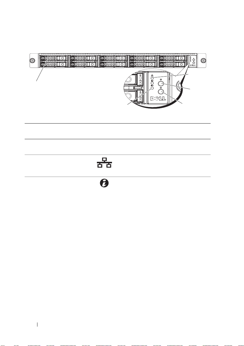
Figure 1-2. Front-Panel Features—2.5-Inch Hard-Drive Systems
1
5
4
3
2
Item Indicator, Button,
or Connector
1 Hard drives Up to ten hot-swappable 2.5-inch hard
2 Ethernet connectors 1
and 2
3 System identification
indicator/button
Icon Description
drives.
Lights green when a connection is
made to the NIC port, blinks when
there is traffic on the NIC port.
The system identification button can be
used to locate a particular system and
system board within a rack.
When the button is pushed, the blue
system status indicators on the front
and the back blink until the button
is pushed again.
16 About Your System
Item Indicator, Button,
or Connector
4Power-on
indicator/power
button
Icon Description
The power-on indicator lights
when the system power is on.
The power button controls the
DC power supply output to the system.
NOTE: When powering on the system,
the video monitor can take from several
seconds to over 2 minutes to display an
image, depending on the amount of
memory installed in the system.
NOTE: On ACPI-compliant operating
systems, turning off the system using the
power button causes the system to
perform a graceful shutdown before
power to the system is turned off.
NOTE: To force an ungraceful shutdown,
press and hold the power button for
5 seconds.
5 Fault LED Displays status/errors and is controlled
by BMC.
About Your System 17
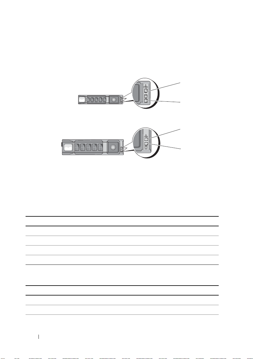
Hard-Drive Indicator Patterns
1
2
1
2
2.5-inch hard-drive carrier
3.5-inch hard-drive carrier
Figure 1-3. Hard-Drive Indicators
1 hard-drive activity indicator
(green)
Table 1-1. Hard Drive Indicators—On-Board SATA Ports
Drive-Activity Indicator/Drive-Status Indicator Condition
Off/Off No drive
Steady green/Off No access
Steady green/Steady green Drive online
Steady green/Blinks green Drive is present or in idle stage
Table 1-2. Hard Drive Indicators—SAS/SATA Add-on Cards
Drive-Activity Indicator/Drive-Status Indicator Condition
Off/Off No drive
Steady green/Off No access
Steady green/Steady green Drive online
18 About Your System
2 hard-drive status indicator
(green and amber)
Table 1-2. Hard Drive Indicators—SAS/SATA Add-on Cards
1
45
6
78
9
3
2
10
Drive-Activity Indicator/Drive-Status Indicator Condition
Steady green/Blinks green Drive is present or in idle stage
Steady amber/Off Drive failed
Steady amber/Steady green Drive rebuilding
(continued)
Back-Panel Features and Indicators
Figure 1-4. Back-Panel Features
Item Indicator, Button, or
Connector
1 Power supply 650 W
2 Power LED Lights green when the power supply is
3 Fault LED Displays status/errors and is controlled
4 System identification
indicator
5 Serial connector Connects a serial device to the system.
6 Video connector Connects a VGA display to the system.
Icon Description
functioning properly.
by BMC.
Both the systems management software
and the identification buttons located
on the front can cause the indicator to
flash blue to identify a particular
system and system board.
Lights amber when the system needs
attention due to a problem.
About Your System 19
Item Indicator, Button, or
1
2
Connector
7 USB connectors (2) Connects USB devices to the system.
8 KVM over IP Port Dedicated management port.
9 Ethernet connectors (2) Embedded 10/100/1000 NIC connector.
10 Mezzanine-card cover Remove this cover before installing
Icon Description
The ports are USB 2.0-compliant.
mezzanine card.
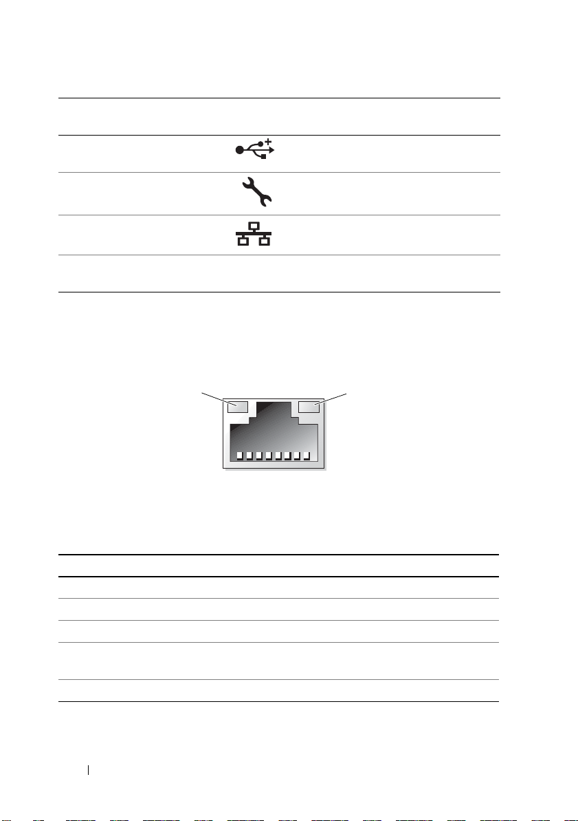
NIC Indicator Codes
Figure 1-5. NIC Indicators
1 link indicator 2 activity indicator
Table 1-3. NIC Speed Indicator Codes
NIC Speed Indicator Condition
Steady amber Link at 1 Gbps
Blinks amber Identify port with 1 Gbps connection
Steady green Link at 100 Mbps
Blinks green Identify port with 10 Mbps or 100 Mbps
connection
Green off Link at 10 Mbps
20 About Your System

Table 1-4. NIC Indicator Codes—BMC
NIC Indicator Condition
Steady green Link LAN/No access
Blinks green Accessing LAN
Green off Idle
Table 1-5. NIC Speed Indicator Codes (KVM Over IP Port)
NIC Speed Indicator Condition
Steady green Link at 100 Mbps
Green off Link at 10 Mbps
Power and System Board Indicator Codes
The LEDs on the system front and back panel display error codes during
system startup. Systems with 2.5-inch or 3.5-inch hard drives share the
same LEDs on the front and back panel. Table 1-6 lists the status associated
with the error codes.
Table 1-6. Power and System Board Indicator Codes
Power-On Indicator Condition
Steady green, Amber off Power On (S0/S1)
Green off, Blinks amber BMC critical condition event in power
off mode (S4/S5)
Green, Blinks amber BMC critical condition event in power
off mode (S0/S1)
About Your System 21

Table 1-7. System Identification Indicators
System Identification Indicator Condition
Steady blue IPMI using chassis identify command on or
ID button press identification on.
Blinks blue blinking Only IPMI using chassis identify command
blink on.
Blue off IPMI using chassis identify command off or
ID button press identification off.
Table 1-8. Power Indicator Codes
Power Indicator Condition
Steady green Power supply is on (AC OK/DC OK) or in
standby mode (90–264 VAC)
Steady yellow Power supply faulty
(UVP/OVP/OCP/SCP/OTP/Fan Fault)
Yellow off Power supply is off or AC input
voltage is out of normal operating range
(90 VAC–264 VAC)
Table 1-9. Fault Indicator Codes
Fault Indicator Condition
Amber blinking System failure
or
Non-critical failure: non-critical fan,
voltage, temperature state, or CPU thermal
trip.
Amber off No system failure
or
Off
22 About Your System

POST Error Codes
Code Log in BMC Error Message Corrective Action
0000 Yes Timer Error Remove AC power to the system for
10 seconds and restart the system.
If the problem persists, see "Getting
Help" on page 123.
0003 Yes CMOS Battery Low See "Troubleshooting the System Battery"
on page 104.
0004 Yes CMOS Settings
Wro ng
0005 Yes CMOS Checksum
Bad
000B Yes CMOS memory size
Wro ng
000C Yes RAM R/W test failed Remove AC power to the system for
000E Yes A: Driver Error See "Troubleshooting a Hard Drive" on
000F Yes B: Driver Error See "Troubleshooting a Hard Drive" on
0012 Yes CMOS Date/Time
Not Set
Remove AC power to the system for
10 seconds and restart the system.
If the problem persists, see "Getting
Help" on page 123.
Remove AC power to the system for
10 seconds and restart the system.
If the problem persists, see "Getting
Help" on page 123.
Remove AC power to the system for
10 seconds and restart the system.
If the problem persists, see "Getting
Help" on page 123.
10 seconds and restart the system.
If the problem persists, see "Getting
Help" on page 123.
page 109.
page 109.
Remove AC power to the system for
10 seconds and restart the system. See
"Troubleshooting the System Battery" on
page 104.
If the problem persists, see "Getting
Help" on page 123.
About Your System 23

Code Log in BMC Error Message Corrective Action
0040 Yes Refresh timer test
failed
0041 Yes Display memory test
failed
0042 Yes CMOS Display Type
Wrong
0044 Yes DMA Controller
Error
0045 Yes DMA-1 Error See "Troubleshooting System Memory"
0046 Yes DMA-2 Error See "Troubleshooting System Memory"
0047 Yes Unknown BIOS
error.
0048 Yes Password check
failed
Remove AC power to the system for
10 seconds and restart the system.
If the problem persists, see "Getting
Help" on page 123.
Remove AC power to the system for
10 seconds and restart the system.
If the problem persists, see "Getting
Help" on page 123.
Remove AC power to the system for
10 seconds and restart the system.
If the problem persists, see "Getting
Help" on page 123.
See "Troubleshooting System Memory"
on page 107.
If the problem persists, see "Getting
Help" on page 123.
on page 107.
If the problem persists, see "Getting
Help" on page 123.
on page 107.
If the problem persists, see "Getting
Help" on page 123.
Remove AC power to the system for
10 seconds and restart the system.
If the problem persists, see "Getting
Help" on page 123.
Reset password. See "Jumper Settings" on
page 116.
If the problem persists, see "Getting
Help" on page 123.
24 About Your System

Code Log in BMC Error Message Corrective Action
0049 Yes Unknown BIOS
error.
004A Yes Unknown BIOS
error.
004B Yes Unknown BIOS
error.
005E Yes Password check
failed
005D Yes S.M.A.R.T.
Command Failed
S.M.A.R.T. Status
BAD, Backup and
Replace
0060 Yes Primary Master Hard
Disk Error
0061 Yes Primary Salve Hard
Disk Error
0062 Yes Secondary Master
Hard Disk Error
0063 Yes Secondary Salve
Hard Disk Error
0080 Yes Primary Master
Drive - ATAPI
Incompatible
0081 Yes Primary Salve Drive -
ATAPI Incompatible
Remove AC power to the system for
10 seconds and restart the system.
If the problem persists, see "Getting
Help" on page 123.
Remove AC power to the system for
10 seconds and restart the system.
If the problem persists, see "Getting
Help" on page 123.
Remove AC power to the system for
10 seconds and restart the system.
If the problem persists, see "Getting
Help" on page 123.
Reset password. See "Jumper Settings" on
page 116.
If the problem persists, see "Getting
Help" on page 123.
See "Getting Help" on page 123.
See "Troubleshooting a Hard Drive" on
page 109.
See "Troubleshooting a Hard Drive" on
page 109.
See "Troubleshooting a Hard Drive" on
page 109.
See "Troubleshooting a Hard Drive" on
page 109.
See "Troubleshooting a Hard Drive" on
page 109.
See "Troubleshooting a Hard Drive" on
page 109.
About Your System 25

Code Log in BMC Error Message Corrective Action
0082 Yes Secondary Master
Drive - ATAPI
Incompatible
0083 Yes Secondary Slave
Drive - ATAPI
Incompatible
0101 Yes Warning! This
system board does
not support the
power requirements
of the installed
processor. The
processor will be run
at a reduced
frequency, which will
impact system
performance.
0102 Yes Error! The CPU
Core to Bus ratio or
VID configuration
has failed! Please
enter BIOS Setup
and re-config it.
0120 Yes Thermal Failure
detected by
PROCHOT#.
0121 Yes Thermal Failure
detected by
PROCHOT#.
See "Troubleshooting a Hard Drive" on
page 109.
See "Troubleshooting a Hard Drive" on
page 109.
Ensure that your processors match and
conform to the type described in the
processor technical specifications
outlined in your system’s Getting Started
Guide.
See "Troubleshooting Processors" on
page 112.
The message is displayed on the screen,
an error is logged to the SEL, and user
input is required to continue. The user
can take immediate corrective action or
choose to continue booting.
Ensure that the processor heat sinks are
properly installed.
See "Troubleshooting Processors" on
page 112 and "Troubleshooting System
Cooling Problems" on page 106.
Ensure that the processor heat sinks are
properly installed.
See "Troubleshooting Processors" on
page 112 and "Troubleshooting System
Cooling Problems" on page 106.
26 About Your System

Code Log in BMC Error Message Corrective Action
0122 Yes Thermal Failure
detected by
PROCHOT#.
0123 Yes Thermal Failure
detected by
PROCHOT#.
0124 Yes Thermal Failure
detected by
PROCHOT#.
0125 Yes Thermal Failure
detected by
PROCHOT#.
0126 Yes Thermal Failure
detected by
PROCHOT#.
0127 Yes Thermal Failure
detected by
PROCHOT#.
0150 Yes Processor failed
BIST
Ensure that the processor heat sinks are
properly installed.
See "Troubleshooting Processors" on
page 112 and "Troubleshooting System
Cooling Problems" on page 106.
Ensure that the processor heat sinks are
properly installed.
See "Troubleshooting Processors" on
page 112 and "Troubleshooting System
Cooling Problems" on page 106.
Ensure that the processor heat sinks are
properly installed.
See "Troubleshooting Processors" on
page 112 and "Troubleshooting System
Cooling Problems" on page 106.
Ensure that the processor heat sinks are
properly installed.
See "Troubleshooting Processors" on
page 112 and "Troubleshooting System
Cooling Problems" on page 106.
Ensure that the processor heat sinks are
properly installed.
See "Troubleshooting Processors" on
page 112 and "Troubleshooting System
Cooling Problems" on page 106.
Ensure that the processor heat sinks are
properly installed.
See "Troubleshooting Processors" on
page 112 and "Troubleshooting System
Cooling Problems" on page 106.
Remove AC power to the system for 10
seconds and restart the system.
If the problem persists, see "Getting
Help" on page 123.
About Your System 27

Code Log in BMC Error Message Corrective Action
0151 Yes Processor failed
BIST
0152 Yes Processor failed
BIST
0153 Yes Processor failed
BIST
0154 Yes Processor failed
BIST
0155 Yes Processor failed
BIST
0156 Yes Processor failed
BIST
0157 Yes Processor failed
BIST
0160 Yes Processor missing
microcode
Remove AC power to the system for
10 seconds and restart the system.
If the problem persists, see "Getting
Help" on page 123.
Remove AC power to the system for
10 seconds and restart the system.
If the problem persists, see "Getting
Help" on page 123.
Remove AC power to the system for
10 seconds and restart the system.
If the problem persists, see "Getting
Help" on page 123.
Remove AC power to the system for
10 seconds and restart the system.
If the problem persists, see "Getting
Help" on page 123.
Remove AC power to the system for
10 seconds and restart the system.
If the problem persists, see "Getting
Help" on page 123.
Remove AC power to the system for
10 seconds and restart the system.
If the problem persists, see "Getting
Help" on page 123.
Remove AC power to the system for
10 seconds and restart the system.
If the problem persists, see "Getting
Help" on page 123.
A BIOS update is required.
If the problem persists, see "Getting
Help" on page 123.
28 About Your System

Code Log in BMC Error Message Corrective Action
0161 Yes Processor missing
microcode
0162 Yes Processor missing
microcode
0163 Yes Processor missing
microcode
0164 Yes Processor missing
microcode
0165 Yes Processor missing
microcode
0166 Yes Processor missing
microcode
0167 Yes Processor missing
microcode
0180 Yes BIOS does not
support current
stepping
0181 Yes BIOS does not
support current
stepping
A BIOS update is required.
If the problem persists, see "Getting
Help" on page 123.
A BIOS update is required.
If the problem persists, see "Getting
Help" on page 123.
A BIOS update is required.
If the problem persists, see "Getting
Help" on page 123.
A BIOS update is required.
If the problem persists, see "Getting
Help" on page 123.
A BIOS update is required.
If the problem persists, see "Getting
Help" on page 123.
A BIOS update is required.
If the problem persists, see "Getting
Help" on page 123.
A BIOS update is required.
If the problem persists, see "Getting
Help" on page 123.
Ensure that your processors match
and conform to the type described in
the processor technical
specifications outlined in your
system’s Getting Started Guide.
Ensure that your processors match
and conform to the type described in
the processor technical
specifications outlined in your
system’s Getting Started Guide.
About Your System 29

Code Log in BMC Error Message Corrective Action
0182 Yes BIOS does not
support current
stepping
0183 Yes BIOS does not
support current
stepping
0184 Yes BIOS does not
support current
stepping
0185 Yes BIOS does not
support current
stepping
0186 Yes BIOS does not
support current
stepping
0187 Yes BIOS does not
support current
stepping
0194 Yes CPUID, Processor
family are different
Ensure that your processors match
and conform to the type described in
the processor technical
specifications outlined in your
system’s Getting Started Guide.
Ensure that your processors match
and conform to the type described in
the processor technical
specifications outlined in your
system’s Getting Started Guide.
Ensure that your processors match
and conform to the type described in
the processor technical
specifications outlined in your
system’s Getting Started Guide.
Ensure that your processors match
and conform to the type described in
the processor technical
specifications outlined in your
system’s Getting Started Guide.
Ensure that your processors match
and conform to the type described in
the processor technical
specifications outlined in your
system’s Getting Started Guide.
Ensure that your processors match and
conform to the type described in the
processor technical specifications
outlined in your system’s Getting Started
Guide.
Ensure that your processors match and
conform to the type described in the
processor technical specifications
outlined in your system’s Getting Started
Guide.
30 About Your System
 Loading...