

Dell PowerEdge 2970 User Manual [en, de, es, fr]

Dell™ PowerEdge™ 2970
Information Update

Notes, Cautions, and Warnings
NOTE: A NOTE indicates important information that helps you make better use
of your computer.
CAUTION: A CAUTION indicates potential damage to hardware or loss of data
if instructions are not followed.
WARNING: A WARNING indicates a potential for property damage, personal
injury, or death.
____________________
Information in this document is subject to change without notice.
© 2007–2009 Dell Inc. All rights reserved.
Reproduction of these materials in any manner whatsoever without the written permission of Dell Inc.
is strictly forbidden.
Trademarks used in this text: Dell, the DELL logo, OpenManage, and PowerEdge are trademarks
of Dell Inc. Microsoft and Windows are registered trademarks of Microsoft Corporation in the United
States and/or other countries; Red Hat and Red Hat Enterprise Linux are registered trademarks
of Red Hat, Inc.; SUSE is a registered trademark of Novell Inc.; AMD PowerNow! is a trademark
of Advanced Micro Devices, Inc.
Other trademarks and trade names may be used in this document to refer to either the entities claiming
the marks and names or their products. Dell Inc. disclaims any proprietary interest in trademarks
and trade names other than its own.
November 2009 Rev. A06

Contents
Non-Optimal Memory Configurations . . . . . . . . . . . 5
Regional Hardware Owner’s Manuals
Available on the Web
. . . . . . . . . . . . . . . . . . . 5
Using the Online Diagnostics
System Setup Program Updates
Memory Optimizer Technology Feature
QDMA Mode Feature
Demand-Based Power Management Feature
Additional CPU Information
Default Settings Update
System Start-up Behavior
Overcurrent Events on USB Ports
LCD Status Message Update
System Board Jumpers
. . . . . . . . . . . . . . . 5
. . . . . . . . . . . . . . 6
. . . . . . . 6
. . . . . . . . . . . . . . . . . 6
. . . . 6
. . . . . . . . . . . . . . 6
. . . . . . . . . . . . . . . 7
. . . . . . . . . . . . . . . . . 7
. . . . . . . . . . . . . 7
. . . . . . . . . . . . . . . 8
. . . . . . . . . . . . . . . . . . 9
Creating a BMC User Password. . . . . . . . . . . . . 10
System Memory Update
. . . . . . . . . . . . . . . . . 11
Contents 3

3.5-Inch Chassis Update . . . . . . . . . . . . . . . . . 13
Front Features and Indicators
. . . . . . . . . . . 13
Mixed SAS/SATA Hard Drive Configuration
(3.5-Inch Drives Only)
Removing a 3.5-Inch Drive Blank
Installing a 3.5-Inch Drive Blank
Removing the SAS/SATA Backplane Board
Installing the SAS Backplane Board
SAS/SATA Backplane Board Connectors
. . . . . . . . . . . . . . . . 15
. . . . . . . . . . 15
. . . . . . . . . . 15
. . . . 16
. . . . . . . . 18
. . . . . 19
4 Contents

Non-Optimal Memory Configurations
Memory configurations other than those listed in Table 3-1 and Table 3-2
of the Hardware Owner’s Manual are non-optimal configurations. The POST
may halt when a non-optimal memory configuration is detected and the
following message is displayed:
Non-Optimal Memory Configuration
Press F1 to continue or F2 for Setup
NOTE: Mixing DIMMs of different speeds renders the memory configuration
non-optimal. The system clocks down the performance to the slowest speed
in the DIMM set for the channel.
Regional Hardware Owner’s Manuals Available on the Web
At production time, the translated regional versions of the Hardware Owner’s
Manual were unavailable for inclusion on the Dell OpenManage™
Documentation CD, version 5.2. All versions of the Hardware Owner’s
Manuals that are normally delivered on the CD are available for download
on the Web at support.dell.com.
Using the Online Diagnostics
The online Server Administrator Diagnostics tool mentioned in the section
"Using Server Administration Diagnostics" in the Hardware Owner’s Manual
has been replaced by the online Dell PowerEdge™ Diagnostics suite of
diagnostic programs. Dell PowerEdge Diagnostics includes online diagnostic
tests for chassis and storage components such as hard drives, physical
memory, communications ports, NICs, CMOS, and more.
To assess a system problem, first use the online Dell PowerEdge Diagnostics.
If you are unable to identify the problem using the PowerEdge Diagnostics,
then use the system diagnostics.
The files required to run PowerEdge Diagnostics for systems running
supported Microsoft
at support.dell.com and on the CDs that came with your system. For
information about using diagnostics, see the Dell PowerEdge Diagnostics
User's Guide.
®
Windows® and Linux operating systems are available
Information Update 5

System Setup Program Updates
Memory Optimizer Technology Feature
The current BIOS update provides a memory optimization feature on the
Memory Information screen of the System Setup Program. The Memory
Optimizer Technology option enables you to set the two DRAM controllers
to work independently in parallel 64-bit mode (Advanced ECC is not
available in this mode) or disable the feature to run the controllers in the
default 128-bit mode with Advanced ECC.
QDMA Mode Feature
On the Integrated Devices screen, a QDMA Mode option is now available for
the Embedded SATA field. When set to QDMA Mode, the embedded SATA
controller supports ATAPI devices at an increased data transfer rate than the
PIO rate that is supported in ATA Mode. A device driver must be installed
on your operating system to use QDMA Mode.
Demand-Based Power Management Feature
The Demand-Based Power Management option on the CPU Information
screen of the System Setup Program, which enables AMD PowerNow!™
technology features on your CPU(s), is not supported in Red Hat
®
Linux
SUSE
management. SUSE Linux Enterprise Server 9 supports demand-based power
management on dual-core AMD processors, but not on the newer quad-core
processors.
operating systems prior to version 5.
®
Linux Enterprise Server 10 fully supports demand-based power
®
Enterprise
Additional CPU Information
On the CPU Information screen, the processor fields now indicate the family,
model, and stepping of the specified processor.
6 Information Update

Default Settings Update
The following bullets are updates to information listed in your Hardware
Owner’s Manual.
•On the
Communication
•On the
Baud Rate
Serial Communication
field is
On without Console Redirection
Serial Communication
field is
115200
.
screen, the default setting for the
.
screen, the default setting for the
Serial
Failsafe
System Start-up Behavior
Note the following events that may occur on your system during start-up.
• On systems with large memory configurations, the video monitor can take
from several seconds to approximately two minutes to display an image
at startup.
• If you are running the Red Hat Enterprise Linux WS, ES, or AS
(Version 4) (x86-64) operating system, the system may display the
following on-screen message several times during start-up:
clear kernel mapping: mapping is split: will leak
memory
This message is specific to the operating system and does not indicate
a problem with your system hardware.
Overcurrent Events on USB Ports
Some USB devices can cause an overcurrent event on your system’s USB
ports. When this occurs, the system disables one or more of the affected USB
ports, and communication with the attached USB devices is lost. An onscreen system message may appear noting the event, but this is not always
the case, particularly with devices connected to the rear USB ports. If an
overcurrent event disables your system’s USB ports, re-enable the ports by
restarting your system.
If overcurrent events persist, you may need to remove or replace the USB
device(s) connected to your system.
Information Update 7

LCD Status Message Update
Table 1-1 lists updates to the LCD status messages that can occur and the
probable cause for each message. The LCD messages refer to events recorded
in the system event log (SEL). For information on the SEL and configuring
systems management settings, see your systems management software
documentation.
Table 1-1. LCD Status Messages
Code Text Causes Corrective Actions
E1232 VDD 12V
PS# PwrGd
E141C CPU
Mismatch
AC power was lost on
the specified power
supply while the system
was powered on. If AC
power was not lost, the
specified power supply
has failed.
The existing CPU
pairing in the system is
not supported.
If AC power was lost, this message
is information only. If the power
supply has failed, see "Getting
Help" in your Hardware Owner’s
Manual.
Change the CPUs to a matched
pair or other valid configuration.
8 Information Update
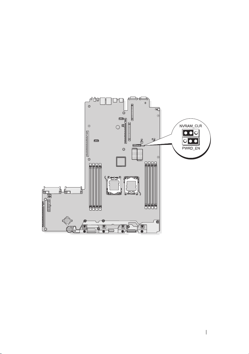
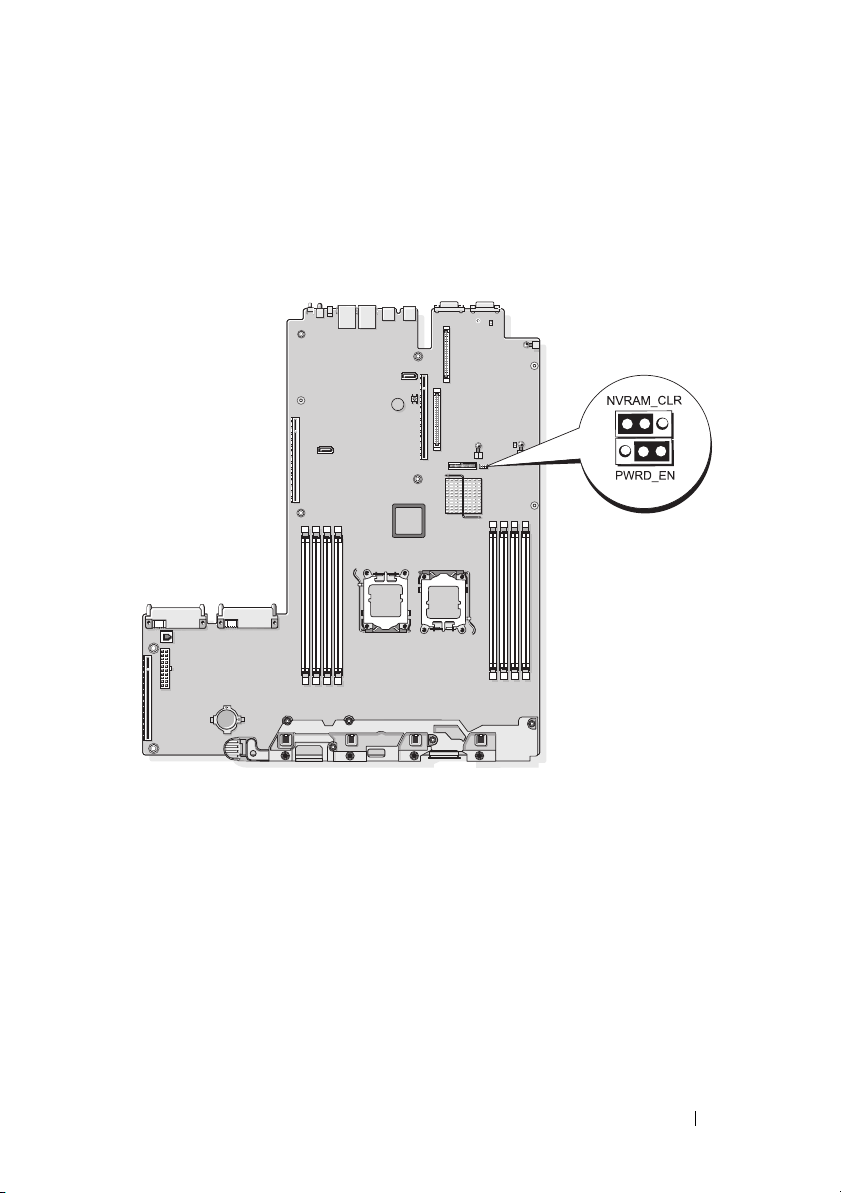
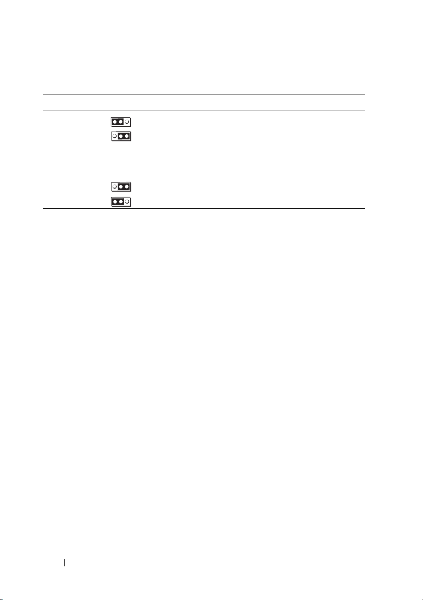
System Board Jumpers
The jumper settings shown in Figure 6-1 and described in Table 6-1 of your
system’s Hardware Owner’s Manual are incorrect. The correct settings are
shown in Figure 1-1 and described in Table 1-2.
Figure 1-1. System Board Jumpers
Information Update 9
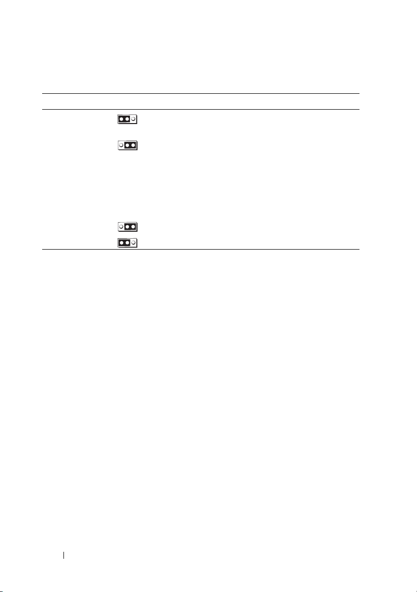
Table 1-2. System Board Jumper Settings
Jumper Setting Description
NVRAM_CLR (default) The configuration settings are retained
at system boot.
The configuration settings are cleared at
the next system boot. (If the configuration
settings become corrupted to the point where
the system will not boot, install the jumper
and boot the system. Remove the jumper
before restoring the configuration
information.)
PWRD_EN
(default) The password feature is enabled.
The password feature is disabled.
Creating a BMC User Password
You must assign a valid LAN user name and password before you can connect
to your system's Baseboard Management Controller (BMC) using the BMC
Management Utility. There are two methods of creating a LAN user name
and password:
• If you access the BMC Remote Access Utility by pressing <CTRL+E>
during system startup, you can create a LAN user name, and a password
with up to 16 characters. (Note that only one LAN user name and
associated password can be created using this utility.) For information
on this option, see "Baseboard Management Controller Configuration" in
your
Dell OpenManage Baseboard Management Controller Utilities User’s
Guide
.
• If you use the Deployment Toolkit SYSCFG.EXE utility, you can create a
LAN user name, and a password of up to 20 characters using the
passwordaction
New BMC Users" in the BMC
command. For more information, see "Configuring
User’s Guide
.
syscfg
10 Information Update

System Memory Update
The 8-GB DIMMs that are supported on your system are 533-MHz quad-rank
modules. All other sizes of supported DIMMs—512-MB, 1-GB, 2-GB, and
4-GB—are 667-MHz modules. Operating a system with a mix of 533-MHz
and 667-MHz DIMMs forces all DIMMs to operate at the slower 533-MHz
signal rate. Therefore, mixed memory configurations with 8-GB DIMMs are
not supported on your system and will result in an error message at startup
to indicate that the memory configuration is not optimal. Table 1-3 and
Table 1-4 provide updates to your system’s Hardware Owner’s Manual
regarding the currently supported system memory configurations and
memory sparing configurations.
Table 1-3. Memory Configurations
CPU 1 Paired DIMMs
Total System Memory
1 CPU 2 CPUs DIMM 1/2 DIMM 3/4 DIMM 5/6 DIMM7/8
1 GB 2 GB 512 MB 512 MB
2 GB 4 GB 512 MB 512 MB 512 MB 512 MB
2 GB 4 GB 1 GB 1 GB
3 GB 6 GB 1 GB 512 MB 1 GB 512 MB
4 GB 8 GB 1 GB 1 GB 1 GB 1 GB
4 GB 8 GB 2 GB 2 GB
5 GB 10 GB 2 GB 512 MB 2 GB 512 MB
6 GB 12 GB 2 GB 1 GB 2 GB 1 GB
8 GB 16 GB 2 GB 2 GB 2 GB 2 GB
8 GB 16 GB 4 GB 4 GB
9 GB 18 GB 4 GB 512 MB 4 GB 512 MB
10 GB 20 GB 4 GB 1 GB 1 GB 4 GB
12 GB 24 GB 4 GB 2 GB 2 GB 4 GB
16 GB 32 GB 4 GB 4 GB 4 GB 4 GB
16 GB 32 GB 8 GB 8 GB
32 GB 64 GB 8 GB 8 GB 8 GB 8 GB
(Size Per DIMM)
CPU 2 Paired DIMMs
(Size Per DIMM)
Information Update 11
The 8-GB DIMMs that are supported on your system are quad-rank modules.
Using quad-rank DIMMs in a memory sparing configuration provides a
proportionally smaller amount of spared memory than using single- or dualrank DIMMs in a similar configuration. Because memory sparing allocates
spared memory by DIMM ranks, one-fourth of a quad-rank DIMM (one rank
out of four) is spared instead of one-half of a dual-rank DIMM or the full
capacity of a single-rank DIMM. Table 1-4 supersedes the information
provided in your Hardware Owner’s Manual regarding memory sparing
configurations that are supported on your system.
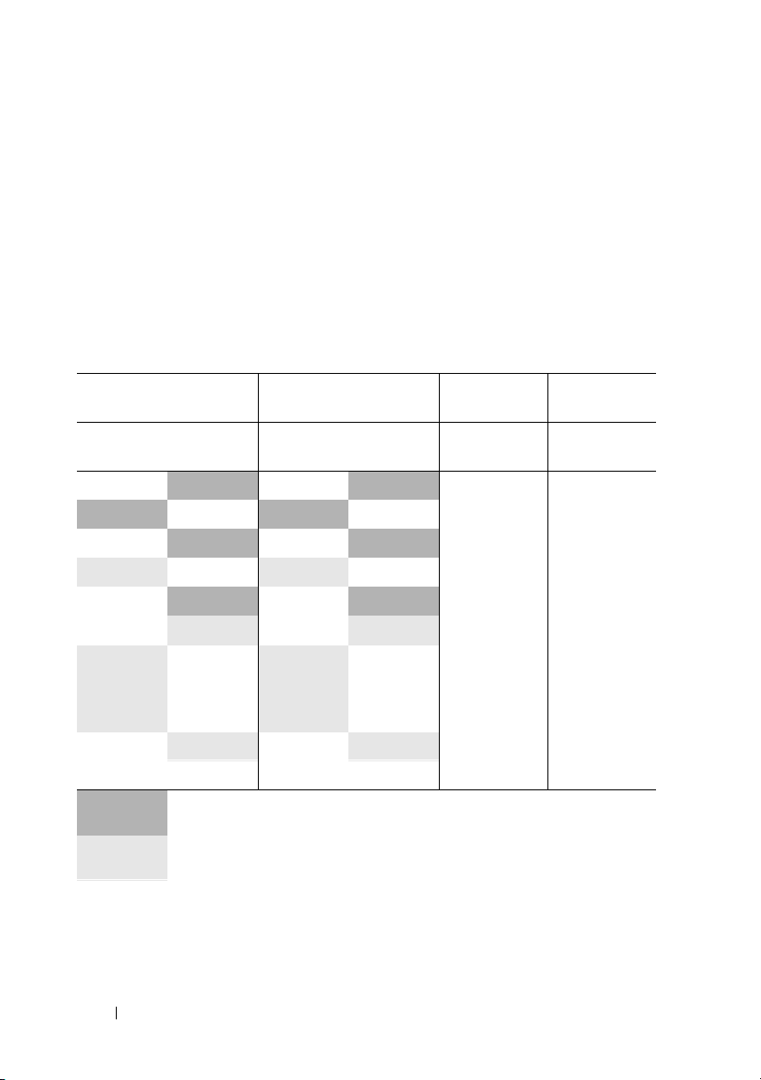
Table 1-4. Memory Sparing in Single- and Dual-Processor Configurations
Processor 1 Processor 2 Available
Memory
DIMM
Pair 1/2
512 MB
1 GB 512 MB 1 GB 512 MB 1 GB / 2 GB 2 GB / 4 GB
1 GB
2 GB 512 MB 2 GB 512 MB 3 GB / 6 GB 2 GB / 4 GB
2 GB
2 GB
4 GB 512 MB 4 GB 512 MB 5 GB / 10 GB 4 GB / 8 GB
4 GB 1 GB 4 GB 1 GB 6 GB / 12 GB 4 GB / 8 GB
4 GB 2 GB 4 GB 2 GB 8 GB / 16 GB 4 GB / 8 GB
4 GB
8 GB 8 GB 8 GB 8 GB 28 GB / 56GB 4 GB / 8 GB
DIMM
Pair 3/4
512 MB 512 MB 512 MB 1 GB / 2 GB 1 GB / 2 GB
1 GB 1 GB 1 GB 2 GB / 4 GB 2 GB / 4 GB
1 GB 2 GB 1 GB 4 GB / 8 GB 2 GB / 4 GB
2 GB 2 GB 2 GB 6 GB / 12 GB 2 GB / 4 GB
4 GB 4 GB 4 GB 12 GB / 24 GB 4 GB / 8 GB
Indicates a spared single-rank DIMM (512-MB or 1-GB). The entire capacity
of this DIMM is reserved for sparing.
Indicates a spared dual-rank DIMM (2-GB or 4-GB). One-half of this DIMM’s
capacity is reserved for sparing.
8-GB DIMMs are quad-rank. One-fourth of this DIMM’s capacity is reserved
for sparing.
DIMM
Pair 5/6
DIMM
Pair 7/8 1 CPU / 2 CPUs 1 CPU / 2 CPUs
Spared
Memory
12 Information Update
3.5-Inch Chassis Update
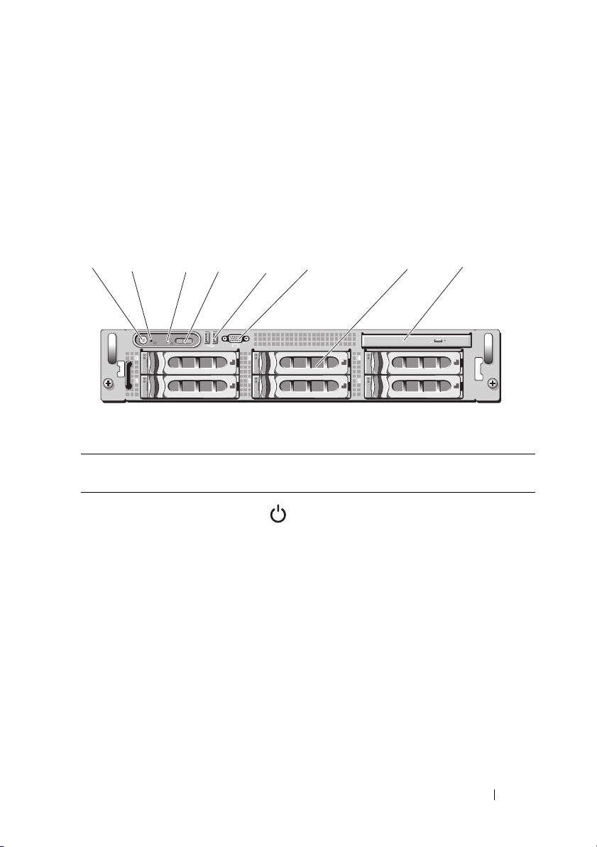
Front Features and Indicators
Figure 1-2 and Table 1-5 identify the controls, indicators, and connectors
located behind the optional rack bezel on the system's front panel.
Figure 1-2. Front-Panel Features and Indicators
2
1
Table 1-5. Front-Panel LED Indicators, Buttons, and Connectors
Item Indicator, Button,
1 Power-on indicator,
3
or Connector
power button
4
Icon Description
6
5
The power-on indicator lights when
the system power is on.
The power button controls the DC power
supply output to the system.
NOTE: If you turn off the system using
the power button and the system is running
an ACPI-compliant operating system,
the system performs a graceful shutdown
before the power is turned off. If the system
is not running an ACPI-compliant operating
system, the power is turned off immediately
after the power button is pressed.
87
Information Update 13
Table 1-5. Front-Panel LED Indicators, Buttons, and Connectors (continued)
Item Indicator, Button,
or Connector
2 NMI button Used to troubleshoot software and device
3 System
identification
button
4 LCD panel Provides system ID, status information,
Icon Description
driver errors when using certain operating
systems. This button can be pressed using
the end of a paper clip.
Use this button only if directed to do so
by qualified support personnel or by the
operating system's documentation.
The identification buttons on the front
and back panels can be used to locate a
particular system within a rack. When
one of these buttons is pushed, the LCD
panel on the front and the blue system
status indicator on the back blink until
one of the buttons is pushed again.
and system error messages.
The LCD lights during normal system
operation. Both the systems management
software and the identification buttons
located on the front and back of the
system can cause the LCD to flash blue
to identify a particular system.
The LCD lights amber when the system
needs attention, and the LCD panel
displays an error code followed by
descriptive text.
NOTE: If the system is connected to AC
power and an error has been detected, the
LCD lights amber regardless of whether the
system has been powered on.
5 USB connectors
(2)
Connects USB 2.0-compliant devices
to the system.
14 Information Update

Table 1-5. Front-Panel LED Indicators, Buttons, and Connectors (continued)
Item Indicator, Button,
or Connector
6 Video connector Connects a monitor to the system.
7 Hard drives (6) Up to six 3.5-inch hot-plug hard drives.
8 Optical drive
(optional)
Icon Description
One optional slimline DVD drive.
Mixed SAS/SATA Hard Drive Configuration (3.5-Inch Drives Only)
The 3.5-inch chassis allows two SATA hard drives to be mixed in the hard
drive bays with one to four SAS hard drives. The SAS/SATA configuration
must contain two SATA drives, which must be installed in drive bays 0 and 1.
The remaining drive bays (2 through 5) can only have SAS hard drives or drive
blanks installed.
Removing a 3.5-Inch Drive Blank
CAUTION: To maintain proper system cooling, all empty hard-drive bays must
have drive blanks installed. If you remove a hard-drive carrier from the system
and do not reinstall it, you must replace the carrier with a drive blank.
1
Remove the front bezel, if attached. See "Removing the Front Bezel"
in your
2
Insert your finger under the shrouded end of the blank and press
in on the latch to eject the blank outward from the bay.
3
Pry the ends of the blank outward until the blank is free.
Hardware Owner’s Manual
.
Installing a 3.5-Inch Drive Blank
The drive blank is keyed to ensure correct insertion into the drive bay.
To install a 3.5-inch drive blank, insert the keyed side of the blank into
the drive bay and press evenly on the other end of the blank until it is fully
inserted and latched.
Information Update 15

Removing the SAS/SATA Backplane Board
WARNING: Only trained service technicians are authorized to remove the system
cover and access any of the components inside the system. See your Product
Information Guide for complete information about safety precautions, working
inside the computer, and protecting against electrostatic discharge.
1
Turn off the system and attached peripherals, and disconnect the system
from the electrical outlet.
2
Open the system. See "Opening the System" in your
Manual
3
Open the drive-carrier release handle on each hard drive and partially
.
extend all of the hard drives from their bays. See Figure 1-3.
NOTE: If you choose to remove the hard drives, be sure to record which hard
drive you remove from which bay. See "Removing a Hot-Plug Hard Drive"
in your Hardware Owner’s Manual.
Hardware Owner’s
16 Information Update
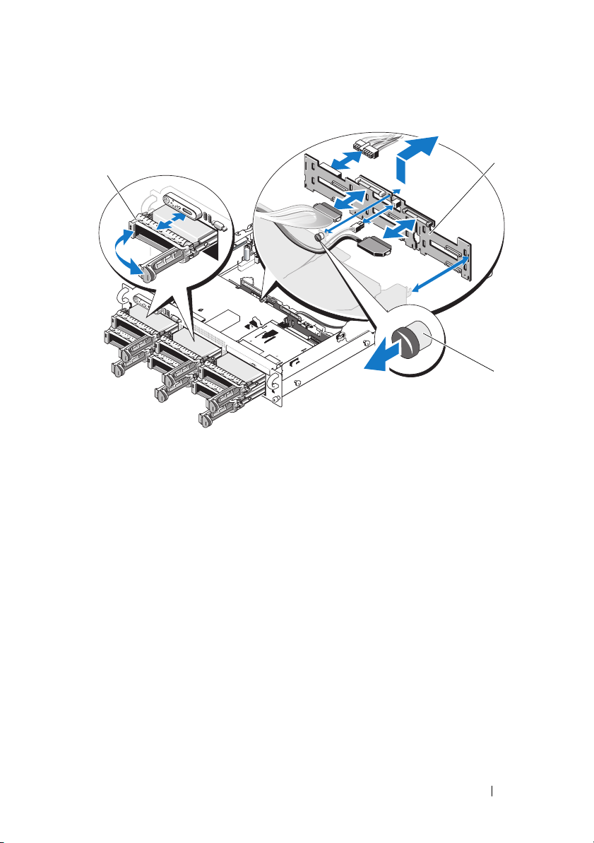
Figure 1-3. SAS/SATA Backplane Board Removal
1
1 drive carrier 2 SAS backplane board
3 SAS-backplane board release pin
4
If present, disconnect the optical drive power cable from the SAS/SATA
backplane board. See Figure 1-4 for the location of the optical drive power
connector.
5
Disconnect the SAS cable(s) from the backplane connectors.
See Figure 1-4 for the location of the SAS cable connectors.
6
If an optical drive is installed, disconnect the data cable from the back
of the optical drive.
7
If present, remove the storage controller daughter card. See "Removing
a SAS Controller Daughter Card" in your
Hardware Owner’s Manual
2
3
.
Information Update 17

8
Remove the SAS backplane board:
a
Pull the SAS-backplane board release pin. See Figure 1-3.
b
While pulling the release pin, tilt the backplane board toward the back
of the system.
c
Lift the backplane board from its securing tabs and remove
the backplane board from the chassis.
Installing the SAS Backplane Board
WARNING: Only trained service technicians are authorized to remove the system
cover and access any of the components inside the system. See your Product
Information Guide for complete information about safety precautions, working
inside the computer, and protecting against electrostatic discharge.
1
Place the SAS backplane board so that the securing tabs on the drive cage
are fully inserted into the securing slots on the backplane board.
See Figure 1-3.
2
Pull the SAS-backplane board release pin. See Figure 1-3.
3
While pulling the release pin, tilt the SAS backplane board toward the
front of the system until it stops, then release the release pin and ensure
that it snaps into place.
4
Reinstall the SAS controller daughter card. See "Installing a SAS
Controller Daughter Card" in your
5
Reattach the SAS controller daughter card cables and the control panel
Hardware Owner’s Manual
cable.
6
Reinsert the hard drives.
7
If applicable, reconnect the optical drive power cable to the backplane
board. See "Installing the Optical Drive" in your
Manual
8
Close the system. See "Closing the System" in your
Manual
.
.
Hardware Owner’s
Hardware Owner’s
.
18 Information Update
SAS/SATA Backplane Board Connectors
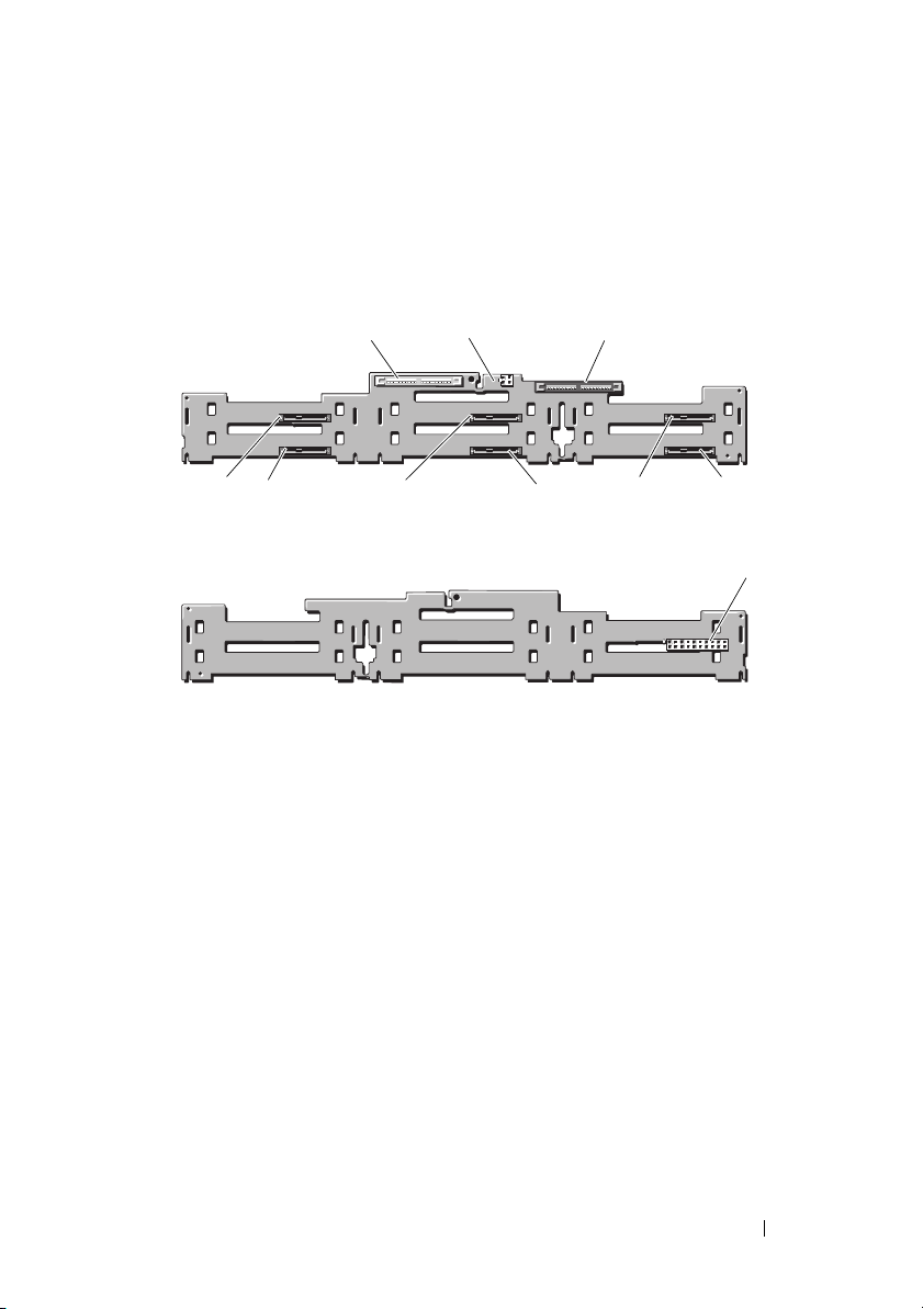
Figure 1-4 shows the location of the connectors on the SAS/SATA backplane
board.
Figure 1-4. SAS Backplane Board Components: 3.5-inch x4 Option
1
10
9
1 primary SAS (SAS_A) 2 optical drive power (CD_PWR)
3 secondary SAS (SAS_B) 4 drive 5 (SASDRV5)
5 backplane power (BP_PWR) 6 drive 4 (SASDRV4)
7 drive 3 (SASDRV3) 8 drive 2 (SASDRV2)
9 drive 1 (SASDRV1) 10 drive 0 (SASDRV0)
2
8
front
back
3
7
6
4
5
Information Update 19

20 Information Update

Dell™ PowerEdge™ 2970
信息更新

注、小心和警告
注:“注”表示可以帮助您更好地使用计算机的重要信息。
小心:“小心”表示如果不遵循说明,就有可能损坏硬件
或导致数据丢失。
警告:“警告”表示可能会造成财产损失、人身伤害甚至死亡。
____________________
本说明文件中的信息如有更改,恕不另行通知。
© 2007–2009 Dell Inc.
未经
Dell Inc.
本文中使用的商标:
Microsoft
Red Hat
的注册商标;
本说明文件中述及的其它商标和产品名称是指拥有相应商标和产品名称的公司或其制造
的产品。
2009 年 11
书面许可,严禁以任何形式复制这些材料。
和
Windows
和
Red Hat Enterprise Linux
AMD PowerNow!
Dell Inc.
月
版权所有,翻印必究。
Dell、DELL
是 Microsoft Corporation
对其它公司的商标和产品名称不拥有任何所有权。
Rev. A06
徽标、
OpenManage
是 Red Hat, Inc.
是 Advanced Micro Devices, Inc.
和
在美国和/或其它国家/地区的注册商标;
PowerEdge
的注册商标;
是 Dell Inc.
SUSE
的商标。
的商标。
是 Novell Inc.

目录
非优化的内存配置 . . . . . . . . . . . . . . . . . . .
可以从相关
的区域版本
使用联机诊断
系统设置程序更新
内存优化器技术功能
QDMA Mode (QDMA 模式)功能
站点上获取 《硬件用户手册》
Web
. . . . . . . . . . . . . . . . . . . . . . .
. . . . . . . . . . . . . . . . . . . . . .
. . . . . . . . . . . . . . . . . . .
. . . . . . . . . . . . . . . 26
. . . . . . . . 26
Demand-Based Power Management
(基于需求的电源管理)功能
其它 CPU 信息
默认设置更新
系统启动行为
端口上的过电流事件
USB
状态信息更新
LCD
系统板跳线
创建
BMC
用户密码
. . . . . . . . . . . . . . . . . . . 26
. . . . . . . . . . . . . . . . . . . 27
. . . . . . . . . . . . . . . . . . . . . .
. . . . . . . . . . . . . . . . . . .
. . . . . . . . . . . . . . . . . . . . . . .
. . . . . . . . . . . . . . . . . . .
. . . . . . . . . . . . . . .
. . . . . . . . . . 26
25
25
25
26
27
27
28
29
30
系统内存更新
. . . . . . . . . . . . . . . . . . . . . .
目录 23
31

英寸机箱更新
3.5
. . . . . . . . . . . . . . . . . . . .
前面板部件和指示灯
混合 SAS/SATA 硬盘驱动器配置
(仅适用于 3.5 英寸驱动器)
卸下 3.5 英寸驱动器挡片
拆除 3.5 英寸驱动器挡片
卸下 SAS/SATA 背板
安装 SAS 背板
. . . . . . . . . . . . . . . . . . . 37
SAS/SATA 背板连接器
33
. . . . . . . . . . . . . . . 33
. . . . . . . . . . . 34
. . . . . . . . . . . . . 35
. . . . . . . . . . . . . 35
. . . . . . . . . . . . . . . . 35
. . . . . . . . . . . . . . . 38
24 目录

非优化的内存配置
除《硬件用户手册》表
配置。如果检测到非优化的内存配置,
Non-Optimal Memory Configuration
(非优化的内存配置)
Press F1 to continue or F2 for Setup
(按
继续,按
F1
注:将不同速率的
系统会将通道
可以从相关
3-1 和 3-2
进行设置)
F2
DIMM
集的性能减为最慢速率。
DIMM
Web
中所列的配置之外,其它配置均属非优化
会中止,并显示以下信息:
POST
混合使用会导致内存配置无法达到优化。
站点上获取《硬件用户手册》
的区域版本
在制作
户手册》的区域翻译版本,因此这些版本未包括在该
会提供的所有《硬件用户手册》版本都能通过
5.2
版的《
Dell OpenManage
™ 说明文件》
support.dell.com
时,尚未取得《硬件用
CD
中。该
CD
CD
网站下载。
上通常
使用联机诊断
《硬件用户手册》的“使用服务器管理诊断程序”一节中所提到的在线服务
器管理员诊断程序工具已由诊断程序的
件所取代。
盘驱动器、物理内存、通信端口、
要判定系统问题,请先使用联机的
PowerEdge Diagnostics
在运行支持的
PowerEdge Diagnostics
中找到。有关使用诊断程序的信息,请参阅
CD
User's Guide
Dell PowerEdge Diagnostics
无法识别出问题,请使用系统诊断程序。
Microsoft® Windows® 和 Linux
所需的文件可以在
(
Dell PowerEdge Diagnostics
Dell PowerEdge
包括用来检测机箱和存储组件(如硬
NIC、CMOS
Dell PowerEdge Diagnostics
™
Diagnostics
等)的联机诊断检测。
操作系统的系统上运行
support.dell.com
Dell PowerVault Diagnostics
用户指南)。
上和系统附带的
联机套
。如果使用
信息更新 25

系统设置程序更新
内存优化器技术功能
当前的
幕上提供了内存优化功能。通过
技术)选项可以将两个
在这种模式下不可用)下独立运行,或者禁用此功能,使控制器在默认的
位模式运行 (可运行高级
128
更新在系统设置程序的
BIOS
DRAM
Memory Information
Memory Optimizer Technology
控制器设置为在
)。
ECC
位并行模式 (高级
64
(内存信息)屏
(内存优化
ECC
QDMA Mode(QDMA
在
Integrated Devices
(
QDMA
为
QDMA Mode(QDMA
Mode
要使用
程序。
模式)选项,用于
(
模式)支持的
ATA
QDMA Mode(QDMA
Demand-Based Power Management
系统设置程序的
Power Management
AMD PowerNow!
®
Linux
SUSE® Linux Enterprise Server 10
Linux Enterprise Server 9
但在较新的四核处理器上不支持这一功能。
其它
现在,
器的系列、型号和步进。
操作系统中不受支持。
CPU
CPU Information(CPU
CPU Information(CPU
信息
模式)功能
(集成设备)屏幕中,现在提供了
Embedded SATA
模式)后,嵌入式
速率更快的数据传输速率支持
PIO
模式),必须在操作系统上安装设备驱动
(基于需求的电源管理)功能
信息)屏幕上的
(基于需求的电源管理)选项支持在
™ 技术功能,但在第
在
AMD
信息)屏幕上的处理器字段会显示指定处理
版之前的
5
全面支持基于需求的电源管理。
双核处理器上支持基于需求的电源管理,
QDMA Mode
(嵌入式
SATA
SATA
控制器将使用比
Demand-Based
CPU
Red Hat® Enterprise
)字段。设置
ATA
上使用
SUSE
设备。
ATAPI
26 信息更新

默认设置更新
下面的列表项内容是对《硬件用户手册》中所列信息的更新。
•
在
Serial Communication
(串行通信)字段的默认设置为
(开,控制台重定向不启用)。
•
在
Serial Communication
(故障保护波特率)字段的默认设置为
(串行通信)屏幕中,
On without Console Redirection
(串行通信)屏幕中,
115200
。
Serial Communication
Failsafe Baud Rate
系统启动行为
在启动系统的过程中,注意系统中可能发生的以下事件。
•
在启动带有大型内存配置的系统时,视频显示器可能需要几秒钟到大
约两分钟的时间才能显示图片。
•
如果运行的是
(x86-64)
clear kernel mapping: mapping is split: will leak
memory
此信息特定于操作系统,不表示系统硬件出现故障。
Red Hat Enterprise Linux WS、ES 或 AS
操作系统,系统在启动过程中可能会多次显示以下屏幕信息:
(清除内核映射:映射分散:将导致内存泄漏)
(第4 版)
USB
某些
事件,系统将禁用一个或多个受影响的
设备之间的通信。此时可能会显示系统屏幕信息,提示此事件,但是并不是
所有情况下都会显示此类信息,尤其是在设备连接至背面
况下。如果过电流事件禁用了系统
启用端口。
如果过电流事件仍然存在,您可能需要拔除或替换连接至系统的
USB
端口上的过电流事件
设备可能会导致系统的
USB
设备。
USB
端口发生过电流事件。一旦发生这种
端口,同时中止与受影响
USB
端口的情
USB
端口,可通过重新启动系统来重新
USB
信息更新 27
USB

状态信息更新
LCD
表
列出了可能出现的
1-1
信息引用系统事件日志
LCD
状态信息的更新以及每则信息的可能原因。
LCD
中记录的事件。有关
(SEL)
理设置的信息,请参阅系统管理软件说明文件。
和配置系统管
SEL
表
1-1. LCD
代码 文本 原因 纠正措施
E1232 VDD 12V
E141C CPU
状态信息
PS# PwrGd
Mismatch
在系统通电的情况下,
指定电源设备上的
电源中断。如果
源没有中断,则说明指
定电源设备出现故障。
系统中的现有
对不受支持。
AC
CPU
AC
电
配
如果
AC
供参考。如果电源设备出现故
障,请参阅 《硬件用户手册》
中的 “获得帮助”。
将
CPU
它有效配置。
电源中断,则此信息仅
更改为相匹配的对或其
28 信息更新
系统板跳线
图
所示和《硬件用户手册》表
6-1
图
1-1
所示和表
中所描述的设置才是正确的设置。
1-2
中所描述的跳线设置均不正确。
6-1
图
1-1.
系统板跳线
信息更新 29
表
跳线 设置 说明
NVRAM_CLR
PWRD_EN
系统板跳线设置
1-2.
(默认设置) 系统在引导时保留配置设置。
下一次系统引导时清除配置设置。
(如果配置设置被损坏以至于系统
不能进行引导,请安装跳线并引导系统。
恢复配置信息之前,请拔下跳线。)
(默认设置) 已启用密码功能。
已禁用密码功能。
创建
您必须分配一个有效的
程序连接到系统的底板管理控制器
有两种:
BMC
•
如果在系统启动过程中通过按
程序,则可以创建一个
码。(注意:使用此公用程序,只能创建一个
密码。)有关此选项的信息,请参阅《
器公用程序用户指南》中的“底板管理控制器配置”。
•
如果使用的是
syscfg passwordaction 命令创建一个
超过
“配置新
用户密码
用户名和密码之后,才能使用
LAN
(BMC)
<CTRL+E> 访问 BMC
用户名和一个最长不超过
LAN
Deployment Toolkit SYSCFG.EXE
个字符的密码。有关更多信息,请参阅《
20
用户”。
BMC
。创建
Dell OpenManage
管理公用
BMC
用户名和密码的方法
LAN
远程访问公用
个字符的密
16
用户名和一个对应
LAN
底板管理控制
公用程序,则可以使用
用户名和一个最长不
LAN
用户指南》中的
BMC
30 信息更新
 Loading...