

Page 1

53-1002164-01
®
29 April 2011
Converged Enhanced
Ethernet
Command Reference
Supporting Fabric OS v7.0.0
Page 2

Copyright © 2009-2011 Brocade Communications Systems, Inc. All Rights Reserved.
Brocade, the B-wing symbol, BigIron, DCX, Fabric OS, FastIron, IronPoint, IronShield, IronView, IronWare, JetCore, NetIron,
SecureIron, ServerIron, StorageX, and TurboIron are registered trademarks, and DCFM, Extraordinary Networks, and SAN Health
are trademarks of Brocade Communications Systems, Inc., in the United States and/or in other countries. All other brands,
products, or service names are or may be trademarks or service marks of, and are used to identify, products or services of their
respective owners.
Notice: This document is for informational purposes only and does not set forth any warranty, expressed or implied, concerning
any equipment, equipment feature, or service offered or to be offered by Brocade. Brocade reserves the right to make changes to
this document at any time, without notice, and assumes no responsibility for its use. This informational document describes
features that may not be currently available. Contact a Brocade sales office for information on feature and product availability.
Export of technical data contained in this document may require an export license from the United States government.
The authors and Brocade Communications Systems, Inc. shall have no liability or responsibility to any person or entity with
respect to any loss, cost, liability, or damages arising from the information contained in this book or the computer programs that
accompany it.
The product described by this document may contain “open source” software covered by the GNU General Public License or other
open source license agreements. To find out which open source software is included in Brocade products, view the licensing
terms applicable to the open source software, and obtain a copy of the programming source code, please visit
http://www.brocade.com/support/oscd.
Brocade Communications Systems, Incorporated
Corporate and Latin American Headquarters
Brocade Communications Systems, Inc.
130 Holger Way
San Jose, CA 95134
Tel: 1-408-333-8000
Fax: 1-408-333-8101
E-mail: info@brocade.com
European Headquarters
Brocade Communications Switzerland Sàrl
Centre Swissair
Tour B - 4ème étage
29, Route de l'Aéroport
Case Postale 105
CH-1215 Genève 15
Switzerland
Tel: +41 22 799 5640
Fax: +41 22 799 5641
E-mail: emea-info@brocade.com
Asia-Pacific Headquarters
Brocade Communications Systems China HK, Ltd.
No. 1 Guanghua Road
Chao Yang District
Units 2718 and 2818
Beijing 100020, China
Tel: +8610 6588 8888
Fax: +8610 6588 9999
E-mail: china-info@brocade.com
Asia-Pacific Headquarters
Brocade Communications Systems Co., Ltd. (Shenzhen WFOE)
Citic Plaza
No. 233 Tian He Road North
Unit 1308 – 13th Floor
Guangzhou, China
Tel: +8620 3891 2000
Fax: +8620 3891 2111
E-mail: china-info@brocade.com
Document History
Title Publication number Summary of changes Date
Converged Enhanced Ethernet
Command Reference
Converged Enhanced Ethernet
Command Reference
Converged Enhanced Ethernet
Command Reference
Converged Enhanced Ethernet
Command Reference
Converged Enhanced Ethernet
Command Reference
53-1001217-01 New document. March 2009
53-1001347-01 Updated for Fabric OS
v6.3.0
Added new commands for
802.1x Port Authentication.
53-1001762-01 Added new commands for
IGMP.
53-1002062-01 Added new commands for
iSCSI TLV configuration.
53-1002164-01 Updated for Fabric OS
v7.0.0.
July 2009
March 2010
October 2010
April 2011
Page 3

Contents
About This Document
In this chapter . . . . . . . . . . . . . . . . . . . . . . . . . . . . . . . . . . . . . . . . . . . . xi
How this document is organized . . . . . . . . . . . . . . . . . . . . . . . . . . . . . xi
Supported hardware and software . . . . . . . . . . . . . . . . . . . . . . . . . . . xi
What’s new in this document. . . . . . . . . . . . . . . . . . . . . . . . . . . . . . . xii
Document conventions. . . . . . . . . . . . . . . . . . . . . . . . . . . . . . . . . . . . xii
Text formatting . . . . . . . . . . . . . . . . . . . . . . . . . . . . . . . . . . . . . . . xii
Command syntax conventions . . . . . . . . . . . . . . . . . . . . . . . . . . xiii
Notes, cautions, and warnings . . . . . . . . . . . . . . . . . . . . . . . . . . xiii
Key terms . . . . . . . . . . . . . . . . . . . . . . . . . . . . . . . . . . . . . . . . . . . xiii
Notice to the reader . . . . . . . . . . . . . . . . . . . . . . . . . . . . . . . . . . . . . . xiv
Additional information. . . . . . . . . . . . . . . . . . . . . . . . . . . . . . . . . . . . . xiv
Brocade resources. . . . . . . . . . . . . . . . . . . . . . . . . . . . . . . . . . . . xiv
Other industry resources. . . . . . . . . . . . . . . . . . . . . . . . . . . . . . . xiv
Getting technical help. . . . . . . . . . . . . . . . . . . . . . . . . . . . . . . . . . . . . xv
Document feedback . . . . . . . . . . . . . . . . . . . . . . . . . . . . . . . . . . . . . . xv
Chapter 1 CLI Basics
In this chapter . . . . . . . . . . . . . . . . . . . . . . . . . . . . . . . . . . . . . . . . . . . . 1
Management tools . . . . . . . . . . . . . . . . . . . . . . . . . . . . . . . . . . . . . . . . 1
CEE command line interface . . . . . . . . . . . . . . . . . . . . . . . . . . . . . . . . 1
Saving your configuration changes. . . . . . . . . . . . . . . . . . . . . . . . 2
CEE CLI RBAC permissions . . . . . . . . . . . . . . . . . . . . . . . . . . . . . . 2
Accessing the CEE CLI through the console or Telnet . . . . . . . . 2
Accessing the CEE CLI from the Fabric OS shell . . . . . . . . . . . . . 3
CEE CLI command modes . . . . . . . . . . . . . . . . . . . . . . . . . . . . . . . 3
CEE CLI keyboard shortcuts . . . . . . . . . . . . . . . . . . . . . . . . . . . . . 5
Using the do command as a shortcut . . . . . . . . . . . . . . . . . . . . . 6
Displaying CEE CLI commands and command syntax . . . . . . . . 6
CEE CLI command completion . . . . . . . . . . . . . . . . . . . . . . . . . . . 7
CEE CLI command output modifiers. . . . . . . . . . . . . . . . . . . . . . . 7
Chapter 2 CEE Commands
advertise dcbx-fcoe-app-tlv. . . . . . . . . . . . . . . . . . . . . . . . . . . . . . . . . . 9
advertise dcbx-fcoe-logical-link-tlv . . . . . . . . . . . . . . . . . . . . . . . . . . . 10
advertise dcbx-iscsi-app-tlv . . . . . . . . . . . . . . . . . . . . . . . . . . . . . . . .11
advertise dcbx-tlv . . . . . . . . . . . . . . . . . . . . . . . . . . . . . . . . . . . . . . . .12
Converged Enhanced Ethernet Command Reference iii
53-1002164-01
Page 4

advertise dot1-tlv . . . . . . . . . . . . . . . . . . . . . . . . . . . . . . . . . . . . . . . .13
advertise dot3-tlv . . . . . . . . . . . . . . . . . . . . . . . . . . . . . . . . . . . . . . . .14
advertise optional-tlv . . . . . . . . . . . . . . . . . . . . . . . . . . . . . . . . . . . . . 15
bridge-priority . . . . . . . . . . . . . . . . . . . . . . . . . . . . . . . . . . . . . . . . . . . 16
cee . . . . . . . . . . . . . . . . . . . . . . . . . . . . . . . . . . . . . . . . . . . . . . . . . . . . 17
cee-map . . . . . . . . . . . . . . . . . . . . . . . . . . . . . . . . . . . . . . . . . . . . . . . .18
channel-group . . . . . . . . . . . . . . . . . . . . . . . . . . . . . . . . . . . . . . . . . . .19
cisco-interoperability. . . . . . . . . . . . . . . . . . . . . . . . . . . . . . . . . . . . . .20
clear counters . . . . . . . . . . . . . . . . . . . . . . . . . . . . . . . . . . . . . . . . . . . 21
clear counters access-list mac. . . . . . . . . . . . . . . . . . . . . . . . . . . . . .22
clear dot1x statistics. . . . . . . . . . . . . . . . . . . . . . . . . . . . . . . . . . . . . .23
clear dot1x statistics interface. . . . . . . . . . . . . . . . . . . . . . . . . . . . . . 24
clear ip igmp group . . . . . . . . . . . . . . . . . . . . . . . . . . . . . . . . . . . . . . .25
clear ip igmp groups . . . . . . . . . . . . . . . . . . . . . . . . . . . . . . . . . . . . . .26
clear lacp . . . . . . . . . . . . . . . . . . . . . . . . . . . . . . . . . . . . . . . . . . . . . . . 27
clear lacp counters . . . . . . . . . . . . . . . . . . . . . . . . . . . . . . . . . . . . . . .28
clear lldp neighbors . . . . . . . . . . . . . . . . . . . . . . . . . . . . . . . . . . . . . .29
clear lldp statistics . . . . . . . . . . . . . . . . . . . . . . . . . . . . . . . . . . . . . . .30
clear spanning-tree counter . . . . . . . . . . . . . . . . . . . . . . . . . . . . . . . .31
copy . . . . . . . . . . . . . . . . . . . . . . . . . . . . . . . . . . . . . . . . . . . . . . . . . . .32
debug ip igmp all. . . . . . . . . . . . . . . . . . . . . . . . . . . . . . . . . . . . . . . . .34
debug lacp . . . . . . . . . . . . . . . . . . . . . . . . . . . . . . . . . . . . . . . . . . . . . .35
debug lldp packet . . . . . . . . . . . . . . . . . . . . . . . . . . . . . . . . . . . . . . . . 37
debug spanning-tree. . . . . . . . . . . . . . . . . . . . . . . . . . . . . . . . . . . . . .38
delete . . . . . . . . . . . . . . . . . . . . . . . . . . . . . . . . . . . . . . . . . . . . . . . . . .39
deny (extended ACLs) . . . . . . . . . . . . . . . . . . . . . . . . . . . . . . . . . . . . .40
deny (standard ACLs) . . . . . . . . . . . . . . . . . . . . . . . . . . . . . . . . . . . . . 42
description (interface). . . . . . . . . . . . . . . . . . . . . . . . . . . . . . . . . . . . . 43
description (LLDP). . . . . . . . . . . . . . . . . . . . . . . . . . . . . . . . . . . . . . . .44
dir . . . . . . . . . . . . . . . . . . . . . . . . . . . . . . . . . . . . . . . . . . . . . . . . . . . . .45
disable . . . . . . . . . . . . . . . . . . . . . . . . . . . . . . . . . . . . . . . . . . . . . . . . .46
do . . . . . . . . . . . . . . . . . . . . . . . . . . . . . . . . . . . . . . . . . . . . . . . . . . . . . 47
dot1x authentication. . . . . . . . . . . . . . . . . . . . . . . . . . . . . . . . . . . . . .48
dot1x enable . . . . . . . . . . . . . . . . . . . . . . . . . . . . . . . . . . . . . . . . . . . . 49
dot1x port-control . . . . . . . . . . . . . . . . . . . . . . . . . . . . . . . . . . . . . . . .50
dot1x protocol-version . . . . . . . . . . . . . . . . . . . . . . . . . . . . . . . . . . . .51
dot1x quiet-period. . . . . . . . . . . . . . . . . . . . . . . . . . . . . . . . . . . . . . . .52
iv Converged Enhanced Ethernet Command Reference
53-1002164-01
Page 5

dot1x reauthenticate interface . . . . . . . . . . . . . . . . . . . . . . . . . . . . .53
dot1x reauthentication . . . . . . . . . . . . . . . . . . . . . . . . . . . . . . . . . . . .54
dot1x reauthMax . . . . . . . . . . . . . . . . . . . . . . . . . . . . . . . . . . . . . . . . .55
dot1x timeout re-authperiod . . . . . . . . . . . . . . . . . . . . . . . . . . . . . . . 56
dot1x timeout server-timeout. . . . . . . . . . . . . . . . . . . . . . . . . . . . . . . 57
dot1x timeout supp-timeout. . . . . . . . . . . . . . . . . . . . . . . . . . . . . . . .58
dot1x timeout tx-period. . . . . . . . . . . . . . . . . . . . . . . . . . . . . . . . . . . .59
enable . . . . . . . . . . . . . . . . . . . . . . . . . . . . . . . . . . . . . . . . . . . . . . . . .60
end . . . . . . . . . . . . . . . . . . . . . . . . . . . . . . . . . . . . . . . . . . . . . . . . . . . . 61
erase flash. . . . . . . . . . . . . . . . . . . . . . . . . . . . . . . . . . . . . . . . . . . . . .62
error-disable-timeout enable . . . . . . . . . . . . . . . . . . . . . . . . . . . . . . .63
error-disable-timeout interval . . . . . . . . . . . . . . . . . . . . . . . . . . . . . . .64
exec-timeout . . . . . . . . . . . . . . . . . . . . . . . . . . . . . . . . . . . . . . . . . . . .65
exit . . . . . . . . . . . . . . . . . . . . . . . . . . . . . . . . . . . . . . . . . . . . . . . . . . . . 66
fcoe-map . . . . . . . . . . . . . . . . . . . . . . . . . . . . . . . . . . . . . . . . . . . . . . . 67
fcoeport . . . . . . . . . . . . . . . . . . . . . . . . . . . . . . . . . . . . . . . . . . . . . . . .68
fcoe-priority-bits. . . . . . . . . . . . . . . . . . . . . . . . . . . . . . . . . . . . . . . . . .69
fcoe-vlan . . . . . . . . . . . . . . . . . . . . . . . . . . . . . . . . . . . . . . . . . . . . . . .70
forward-delay. . . . . . . . . . . . . . . . . . . . . . . . . . . . . . . . . . . . . . . . . . . . 71
fos. . . . . . . . . . . . . . . . . . . . . . . . . . . . . . . . . . . . . . . . . . . . . . . . . . . . .72
hello . . . . . . . . . . . . . . . . . . . . . . . . . . . . . . . . . . . . . . . . . . . . . . . . . . . 74
hello-time . . . . . . . . . . . . . . . . . . . . . . . . . . . . . . . . . . . . . . . . . . . . . . .75
instance . . . . . . . . . . . . . . . . . . . . . . . . . . . . . . . . . . . . . . . . . . . . . . . . 76
interface. . . . . . . . . . . . . . . . . . . . . . . . . . . . . . . . . . . . . . . . . . . . . . . . 77
interface vlan. . . . . . . . . . . . . . . . . . . . . . . . . . . . . . . . . . . . . . . . . . . .78
ip igmp last-member-query-interval . . . . . . . . . . . . . . . . . . . . . . . . . .79
ip igmp query-interval . . . . . . . . . . . . . . . . . . . . . . . . . . . . . . . . . . . . .80
ip igmp query-max-response-time . . . . . . . . . . . . . . . . . . . . . . . . . . .81
ip igmp snooping enable (global version) . . . . . . . . . . . . . . . . . . . . .82
ip igmp snooping enable (VLAN version). . . . . . . . . . . . . . . . . . . . . .83
ip igmp snooping fast-leave . . . . . . . . . . . . . . . . . . . . . . . . . . . . . . . .84
ip igmp snooping mrouter. . . . . . . . . . . . . . . . . . . . . . . . . . . . . . . . . . 85
ip igmp snooping mrouter-timeout. . . . . . . . . . . . . . . . . . . . . . . . . . .86
ip igmp snooping querier . . . . . . . . . . . . . . . . . . . . . . . . . . . . . . . . . .87
ip igmp static-group. . . . . . . . . . . . . . . . . . . . . . . . . . . . . . . . . . . . . . .88
iscsi-priority-bits . . . . . . . . . . . . . . . . . . . . . . . . . . . . . . . . . . . . . . . . .89
lacp system-priority . . . . . . . . . . . . . . . . . . . . . . . . . . . . . . . . . . . . . . .90
Converged Enhanced Ethernet Command Reference v
53-1002164-01
Page 6

lacp timeout. . . . . . . . . . . . . . . . . . . . . . . . . . . . . . . . . . . . . . . . . . . . .91
line console . . . . . . . . . . . . . . . . . . . . . . . . . . . . . . . . . . . . . . . . . . . . .92
line vty . . . . . . . . . . . . . . . . . . . . . . . . . . . . . . . . . . . . . . . . . . . . . . . . .93
lldp dcbx-version . . . . . . . . . . . . . . . . . . . . . . . . . . . . . . . . . . . . . . . . .94
lldp disable . . . . . . . . . . . . . . . . . . . . . . . . . . . . . . . . . . . . . . . . . . . . .95
lldp fcoe-priority-bits . . . . . . . . . . . . . . . . . . . . . . . . . . . . . . . . . . . . . .96
lldp iscsi-priority-bits . . . . . . . . . . . . . . . . . . . . . . . . . . . . . . . . . . . . . . 97
lldp profile . . . . . . . . . . . . . . . . . . . . . . . . . . . . . . . . . . . . . . . . . . . . . .98
logout . . . . . . . . . . . . . . . . . . . . . . . . . . . . . . . . . . . . . . . . . . . . . . . . . .99
mac access-group . . . . . . . . . . . . . . . . . . . . . . . . . . . . . . . . . . . . . . .100
mac access-list extended . . . . . . . . . . . . . . . . . . . . . . . . . . . . . . . . .101
mac access-list standard . . . . . . . . . . . . . . . . . . . . . . . . . . . . . . . . .102
mac-address-table . . . . . . . . . . . . . . . . . . . . . . . . . . . . . . . . . . . . . .103
max-age . . . . . . . . . . . . . . . . . . . . . . . . . . . . . . . . . . . . . . . . . . . . . . .104
max-hops . . . . . . . . . . . . . . . . . . . . . . . . . . . . . . . . . . . . . . . . . . . . . .105
mode . . . . . . . . . . . . . . . . . . . . . . . . . . . . . . . . . . . . . . . . . . . . . . . . .106
mtu . . . . . . . . . . . . . . . . . . . . . . . . . . . . . . . . . . . . . . . . . . . . . . . . . . . 107
multiplier . . . . . . . . . . . . . . . . . . . . . . . . . . . . . . . . . . . . . . . . . . . . . .108
permit (extended ACLs). . . . . . . . . . . . . . . . . . . . . . . . . . . . . . . . . . .109
permit (standard ACLs). . . . . . . . . . . . . . . . . . . . . . . . . . . . . . . . . . .111
port-channel path-cost . . . . . . . . . . . . . . . . . . . . . . . . . . . . . . . . . . .112
priority-group-table . . . . . . . . . . . . . . . . . . . . . . . . . . . . . . . . . . . . . .113
priority-table. . . . . . . . . . . . . . . . . . . . . . . . . . . . . . . . . . . . . . . . . . . .114
profile. . . . . . . . . . . . . . . . . . . . . . . . . . . . . . . . . . . . . . . . . . . . . . . . .116
protocol lldp. . . . . . . . . . . . . . . . . . . . . . . . . . . . . . . . . . . . . . . . . . . .117
protocol spanning-tree . . . . . . . . . . . . . . . . . . . . . . . . . . . . . . . . . . .118
pwd. . . . . . . . . . . . . . . . . . . . . . . . . . . . . . . . . . . . . . . . . . . . . . . . . . .119
qos cos. . . . . . . . . . . . . . . . . . . . . . . . . . . . . . . . . . . . . . . . . . . . . . . .120
qos cos-mutation. . . . . . . . . . . . . . . . . . . . . . . . . . . . . . . . . . . . . . . .121
qos cos-traffic-class . . . . . . . . . . . . . . . . . . . . . . . . . . . . . . . . . . . . .122
qos map cos-mutation . . . . . . . . . . . . . . . . . . . . . . . . . . . . . . . . . . .123
qos map cos-traffic-class . . . . . . . . . . . . . . . . . . . . . . . . . . . . . . . . .124
qos queue multicast scheduler . . . . . . . . . . . . . . . . . . . . . . . . . . . .125
qos queue scheduler . . . . . . . . . . . . . . . . . . . . . . . . . . . . . . . . . . . .126
qos rcv-queue multicast rate-limit . . . . . . . . . . . . . . . . . . . . . . . . . .128
qos rcv-queue multicast threshold . . . . . . . . . . . . . . . . . . . . . . . . .129
qos trust cos . . . . . . . . . . . . . . . . . . . . . . . . . . . . . . . . . . . . . . . . . . .130
vi Converged Enhanced Ethernet Command Reference
53-1002164-01
Page 7

quit . . . . . . . . . . . . . . . . . . . . . . . . . . . . . . . . . . . . . . . . . . . . . . . . . . .131
region . . . . . . . . . . . . . . . . . . . . . . . . . . . . . . . . . . . . . . . . . . . . . . . . .132
rename. . . . . . . . . . . . . . . . . . . . . . . . . . . . . . . . . . . . . . . . . . . . . . . .133
resequence access-list mac. . . . . . . . . . . . . . . . . . . . . . . . . . . . . . .134
revision. . . . . . . . . . . . . . . . . . . . . . . . . . . . . . . . . . . . . . . . . . . . . . . .135
rmon alarm . . . . . . . . . . . . . . . . . . . . . . . . . . . . . . . . . . . . . . . . . . . .136
rmon collection . . . . . . . . . . . . . . . . . . . . . . . . . . . . . . . . . . . . . . . . .137
rmon event. . . . . . . . . . . . . . . . . . . . . . . . . . . . . . . . . . . . . . . . . . . . .138
seq (extended MAC ACLs). . . . . . . . . . . . . . . . . . . . . . . . . . . . . . . . .139
seq (standard MAC ACLs) . . . . . . . . . . . . . . . . . . . . . . . . . . . . . . . . . 141
show accounting . . . . . . . . . . . . . . . . . . . . . . . . . . . . . . . . . . . . . . . .142
show calendar . . . . . . . . . . . . . . . . . . . . . . . . . . . . . . . . . . . . . . . . . .143
show cee maps . . . . . . . . . . . . . . . . . . . . . . . . . . . . . . . . . . . . . . . . .144
show clock . . . . . . . . . . . . . . . . . . . . . . . . . . . . . . . . . . . . . . . . . . . . .145
show debug ip igmp . . . . . . . . . . . . . . . . . . . . . . . . . . . . . . . . . . . . .146
show debug lacp . . . . . . . . . . . . . . . . . . . . . . . . . . . . . . . . . . . . . . . .147
show debug lldp . . . . . . . . . . . . . . . . . . . . . . . . . . . . . . . . . . . . . . . .148
show debug spanning-tree . . . . . . . . . . . . . . . . . . . . . . . . . . . . . . . .149
show dot1x . . . . . . . . . . . . . . . . . . . . . . . . . . . . . . . . . . . . . . . . . . . .150
show dot1x all . . . . . . . . . . . . . . . . . . . . . . . . . . . . . . . . . . . . . . . . . .151
show dot1x diagnostics interface . . . . . . . . . . . . . . . . . . . . . . . . . .152
show dot1x interface . . . . . . . . . . . . . . . . . . . . . . . . . . . . . . . . . . . .153
show dot1x session-info interface . . . . . . . . . . . . . . . . . . . . . . . . . .154
show dot1x statistics interface . . . . . . . . . . . . . . . . . . . . . . . . . . . .155
show environment. . . . . . . . . . . . . . . . . . . . . . . . . . . . . . . . . . . . . . .156
show file. . . . . . . . . . . . . . . . . . . . . . . . . . . . . . . . . . . . . . . . . . . . . . .157
show history. . . . . . . . . . . . . . . . . . . . . . . . . . . . . . . . . . . . . . . . . . . .158
show interface. . . . . . . . . . . . . . . . . . . . . . . . . . . . . . . . . . . . . . . . . .159
show ip igmp groups . . . . . . . . . . . . . . . . . . . . . . . . . . . . . . . . . . . . .161
show ip igmp interface . . . . . . . . . . . . . . . . . . . . . . . . . . . . . . . . . . .162
show ip igmp mrouter . . . . . . . . . . . . . . . . . . . . . . . . . . . . . . . . . . . .163
show ip igmp snooping . . . . . . . . . . . . . . . . . . . . . . . . . . . . . . . . . . .164
show ip interface. . . . . . . . . . . . . . . . . . . . . . . . . . . . . . . . . . . . . . . .165
show lacp counter. . . . . . . . . . . . . . . . . . . . . . . . . . . . . . . . . . . . . . .167
show lacp sys-id . . . . . . . . . . . . . . . . . . . . . . . . . . . . . . . . . . . . . . . .168
show line . . . . . . . . . . . . . . . . . . . . . . . . . . . . . . . . . . . . . . . . . . . . . .169
show lldp . . . . . . . . . . . . . . . . . . . . . . . . . . . . . . . . . . . . . . . . . . . . . .170
Converged Enhanced Ethernet Command Reference vii
53-1002164-01
Page 8

show lldp interface . . . . . . . . . . . . . . . . . . . . . . . . . . . . . . . . . . . . . . 171
show lldp neighbors . . . . . . . . . . . . . . . . . . . . . . . . . . . . . . . . . . . . .172
show lldp statistics . . . . . . . . . . . . . . . . . . . . . . . . . . . . . . . . . . . . . . 174
show logging . . . . . . . . . . . . . . . . . . . . . . . . . . . . . . . . . . . . . . . . . . .175
show mac access-group . . . . . . . . . . . . . . . . . . . . . . . . . . . . . . . . . . 176
show mac-address-table. . . . . . . . . . . . . . . . . . . . . . . . . . . . . . . . . .177
show media . . . . . . . . . . . . . . . . . . . . . . . . . . . . . . . . . . . . . . . . . . . .179
show media interface . . . . . . . . . . . . . . . . . . . . . . . . . . . . . . . . . . . .180
show media linecard. . . . . . . . . . . . . . . . . . . . . . . . . . . . . . . . . . . . .181
show port-channel. . . . . . . . . . . . . . . . . . . . . . . . . . . . . . . . . . . . . . .182
show power supply . . . . . . . . . . . . . . . . . . . . . . . . . . . . . . . . . . . . . .183
show privilege . . . . . . . . . . . . . . . . . . . . . . . . . . . . . . . . . . . . . . . . . .184
show processes cpu . . . . . . . . . . . . . . . . . . . . . . . . . . . . . . . . . . . . .185
show processes memory . . . . . . . . . . . . . . . . . . . . . . . . . . . . . . . . .186
show qos flowcontrol interface. . . . . . . . . . . . . . . . . . . . . . . . . . . . .187
show qos interface . . . . . . . . . . . . . . . . . . . . . . . . . . . . . . . . . . . . . .188
show qos maps . . . . . . . . . . . . . . . . . . . . . . . . . . . . . . . . . . . . . . . . .190
show qos queue interface . . . . . . . . . . . . . . . . . . . . . . . . . . . . . . . .191
show qos rcv-queue interface . . . . . . . . . . . . . . . . . . . . . . . . . . . . .192
show qos rcv-queue multicast . . . . . . . . . . . . . . . . . . . . . . . . . . . . .193
show rmon . . . . . . . . . . . . . . . . . . . . . . . . . . . . . . . . . . . . . . . . . . . . .194
show running-config . . . . . . . . . . . . . . . . . . . . . . . . . . . . . . . . . . . . .196
show running-config igmp. . . . . . . . . . . . . . . . . . . . . . . . . . . . . . . . .197
show spanning-tree. . . . . . . . . . . . . . . . . . . . . . . . . . . . . . . . . . . . . .198
show spanning-tree brief . . . . . . . . . . . . . . . . . . . . . . . . . . . . . . . . .200
show spanning-tree interface. . . . . . . . . . . . . . . . . . . . . . . . . . . . . .201
show spanning-tree mst brief. . . . . . . . . . . . . . . . . . . . . . . . . . . . . .202
show spanning-tree mst detail. . . . . . . . . . . . . . . . . . . . . . . . . . . . .203
show spanning-tree mst instance . . . . . . . . . . . . . . . . . . . . . . . . . .205
show spanning-tree mst interface . . . . . . . . . . . . . . . . . . . . . . . . . .206
show startup-config. . . . . . . . . . . . . . . . . . . . . . . . . . . . . . . . . . . . . .207
show statistics access-list mac . . . . . . . . . . . . . . . . . . . . . . . . . . . .208
show system . . . . . . . . . . . . . . . . . . . . . . . . . . . . . . . . . . . . . . . . . . .210
show tech-support. . . . . . . . . . . . . . . . . . . . . . . . . . . . . . . . . . . . . . .211
show users. . . . . . . . . . . . . . . . . . . . . . . . . . . . . . . . . . . . . . . . . . . . .212
show version . . . . . . . . . . . . . . . . . . . . . . . . . . . . . . . . . . . . . . . . . . .213
show vlan. . . . . . . . . . . . . . . . . . . . . . . . . . . . . . . . . . . . . . . . . . . . . .214
viii Converged Enhanced Ethernet Command Reference
53-1002164-01
Page 9

show vlan classifier. . . . . . . . . . . . . . . . . . . . . . . . . . . . . . . . . . . . . .215
shutdown (interface). . . . . . . . . . . . . . . . . . . . . . . . . . . . . . . . . . . . .216
shutdown (Spanning Tree Protocol) . . . . . . . . . . . . . . . . . . . . . . . . . 217
spanning-tree autoedge . . . . . . . . . . . . . . . . . . . . . . . . . . . . . . . . . .218
spanning-tree cost . . . . . . . . . . . . . . . . . . . . . . . . . . . . . . . . . . . . . .219
spanning-tree edgeport . . . . . . . . . . . . . . . . . . . . . . . . . . . . . . . . . .220
spanning-tree guard root . . . . . . . . . . . . . . . . . . . . . . . . . . . . . . . . .221
spanning-tree hello-time. . . . . . . . . . . . . . . . . . . . . . . . . . . . . . . . . .222
spanning-tree instance . . . . . . . . . . . . . . . . . . . . . . . . . . . . . . . . . . .223
spanning-tree link-type . . . . . . . . . . . . . . . . . . . . . . . . . . . . . . . . . . .224
spanning-tree portfast . . . . . . . . . . . . . . . . . . . . . . . . . . . . . . . . . . .225
spanning-tree priority . . . . . . . . . . . . . . . . . . . . . . . . . . . . . . . . . . . .226
spanning-tree restricted-role . . . . . . . . . . . . . . . . . . . . . . . . . . . . . .227
spanning-tree restricted-tcn . . . . . . . . . . . . . . . . . . . . . . . . . . . . . . .228
spanning-tree shutdown. . . . . . . . . . . . . . . . . . . . . . . . . . . . . . . . . .229
spanning-tree tc-flush-standard. . . . . . . . . . . . . . . . . . . . . . . . . . . .230
switchport . . . . . . . . . . . . . . . . . . . . . . . . . . . . . . . . . . . . . . . . . . . . .231
switchport access . . . . . . . . . . . . . . . . . . . . . . . . . . . . . . . . . . . . . . .232
switchport converged . . . . . . . . . . . . . . . . . . . . . . . . . . . . . . . . . . . .233
switchport mode . . . . . . . . . . . . . . . . . . . . . . . . . . . . . . . . . . . . . . . .234
switchport trunk . . . . . . . . . . . . . . . . . . . . . . . . . . . . . . . . . . . . . . . .235
system-description . . . . . . . . . . . . . . . . . . . . . . . . . . . . . . . . . . . . . .236
system-name . . . . . . . . . . . . . . . . . . . . . . . . . . . . . . . . . . . . . . . . . . .237
terminal length . . . . . . . . . . . . . . . . . . . . . . . . . . . . . . . . . . . . . . . . .238
terminal monitor . . . . . . . . . . . . . . . . . . . . . . . . . . . . . . . . . . . . . . . .239
transmit-holdcount . . . . . . . . . . . . . . . . . . . . . . . . . . . . . . . . . . . . . .240
undebug. . . . . . . . . . . . . . . . . . . . . . . . . . . . . . . . . . . . . . . . . . . . . . .241
vlan classifier activate group . . . . . . . . . . . . . . . . . . . . . . . . . . . . . .242
vlan classifier group . . . . . . . . . . . . . . . . . . . . . . . . . . . . . . . . . . . . .243
vlan classifier rule . . . . . . . . . . . . . . . . . . . . . . . . . . . . . . . . . . . . . . .244
write erase. . . . . . . . . . . . . . . . . . . . . . . . . . . . . . . . . . . . . . . . . . . . .245
write memory. . . . . . . . . . . . . . . . . . . . . . . . . . . . . . . . . . . . . . . . . . .246
Converged Enhanced Ethernet Command Reference ix
53-1002164-01
Page 10

x Converged Enhanced Ethernet Command Reference
53-1002164-01
Page 11

About This Document
In this chapter
•How this document is organized . . . . . . . . . . . . . . . . . . . . . . . . . . . . . . . . . . . xi
•Supported hardware and software. . . . . . . . . . . . . . . . . . . . . . . . . . . . . . . . . . xi
•What’s new in this document . . . . . . . . . . . . . . . . . . . . . . . . . . . . . . . . . . . . . xii
•Document conventions . . . . . . . . . . . . . . . . . . . . . . . . . . . . . . . . . . . . . . . . . . xii
•Notice to the reader . . . . . . . . . . . . . . . . . . . . . . . . . . . . . . . . . . . . . . . . . . . . xiv
•Additional information. . . . . . . . . . . . . . . . . . . . . . . . . . . . . . . . . . . . . . . . . . . xiv
•Getting technical help . . . . . . . . . . . . . . . . . . . . . . . . . . . . . . . . . . . . . . . . . . . xv
•Document feedback . . . . . . . . . . . . . . . . . . . . . . . . . . . . . . . . . . . . . . . . . . . . xv
How this document is organized
This document is organized to help you find the information that you want as quickly and easily as
possible.
The document contains the following components:
• Chapter 1, “CLI Basics” describes how to access the switch and the CEE CLI command modes.
• Chapter 2, “CEE Commands” describes the commands to manage the configuration files and
includes other file management commands.
Supported hardware and software
This document includes updated information specific to Fabric OS 7.0.0. The following hardware
platforms are supported in this release of the CEE Administrator’s Guide:
• Brocade 8000
The following blades are supported by this release of the CEE Administrator’s Guide:
• Brocade FCOE10-24 blade
Within this manual, any appearance of the term “Brocade FCoE hardware” is referring to:
• Brocade 8000
• Brocade FCOE10-24 port blade
Converged Enhanced Ethernet Command Reference xi
53-1002164-01
Page 12

Although many different software and hardware configurations are tested and supported by
Brocade Communications Systems, Inc. for Fabric OS 7.0.0, documenting all possible
configurations and scenarios is beyond the scope of this document.
To obtain information about an OS version other than Fabric OS v7.0.0, refer to the documentation
specific to that OS version.
What’s new in this document
This document has been updated for for Fabric OS v7.0.0.
This document has been updated with corrections and updates for defects discovered since the
release of the previous version.
For further information about new features and documentation updates for this release, refer to
the release notes.
Document conventions
This section describes text formatting conventions and important notice formats used in this
document.
Text formatting
The narrative-text formatting conventions that are used are as follows:
bold text Identifies command names
Identifies the names of user-manipulated GUI elements
Identifies keywords and operands
Identifies text to enter at the GUI or CLI
italic text Provides emphasis
Identifies variables
Identifies paths and Internet addresses
Identifies document titles
code text Identifies CLI output
Identifies command syntax examples
For readability, command names in the narrative portions of this guide are presented in mixed
lettercase: for example, switchShow. In actual examples, command lettercase is all lowercase.
xii Converged Enhanced Ethernet Command Reference
53-1002164-01
Page 13

. Command syntax conventions
NOTE
ATTENTION
CAUTION
DANGER
Command syntax in this manual follows these conventions:
TABLE 1 Command syntax conventions
Convention Description
[ ] Default responses to system prompts appear in square brackets.
{x | y | z} A choice of required keywords appears in braces separated by vertical
bars. You must select one.
screen font Examples of information displayed on the screen.
<> Nonprinting characters, for example passwords, appear in angle
brackets
[ ] Keywords or arguments that appear within square brackets are
optional.
bold face font Commands and keywords.
italic Variables for which you supply values.
Notes, cautions, and warnings
The following notices and statements are used in this manual. They are listed below in order of
increasing severity of potential hazards.
A note provides a tip, guidance, or advice, emphasizes important information, or provides a
reference to related information.
An Attention statement indicates potential damage to hardware or data.
A Caution statement alerts you to situations that can be potentially hazardous to you or cause
damage to hardware, firmware, software, or data.
A Danger statement indicates conditions or situations that can be potentially lethal or extremely
hazardous to you. Safety labels are also attached directly to products to warn of these conditions
or situations.
Key terms
For definitions specific to Brocade and Fibre Channel, see the technical glossaries on Brocade
Connect. See “Brocade resources” on page xiv for instructions on accessing Brocade Connect.
Converged Enhanced Ethernet Command Reference xiii
53-1002164-01
Page 14

Notice to the reader
This document may contain references to the trademarks of the following corporations. These
trademarks are the properties of their respective companies and corporations.
These references are made for informational purposes only.
Corporation Referenced Trademarks and Products
Microsoft Corporation Windows, Windows NT, Internet Explorer
Oracle Corporation Oracle, Java
Netscape Communications Corporation Netscape
Red Hat, Inc. Red Hat, Red Hat Network, Maximum RPM, Linux Undercover
Additional information
This section lists additional Brocade and industry-specific documentation that you might find
helpful.
Brocade resources
To get up-to-the-minute information, go to http://my.brocade.com and register at no cost for a user
ID and password.
White papers, online demonstrations, and data sheets are available through the Brocade website
at:
http://www.brocade.com/products-solutions/products/index.page
For additional Brocade documentation, visit the Brocade website:
http://www.brocade.com
Release notes are available on the MyBrocade website and are also bundled with the Fabric OS
firmware.
Other industry resources
For additional resource information, visit the Technical Committee T11 website. This website
provides interface standards for high-performance and mass storage applications for Fibre
Channel, storage management, and other applications:
http://www.t11.org
For information about the Fibre Channel industry, visit the Fibre Channel Industry Association
website:
http://www.fibrechannel.org
xiv Converged Enhanced Ethernet Command Reference
53-1002164-01
Page 15

Getting technical help
Contact your switch support supplier for hardware, firmware, and software support, including
product repairs and part ordering. To expedite your call, have the following information available:
1. General Information
• Switch model
• Switch operating system version
• Error numbers and messages received
• supportSave command output
• Detailed description of the problem, including the switch or fabric behavior immediately
following the problem, and specific questions
• Description of any troubleshooting steps already performed and the results
• Serial console and Telnet session logs
• syslog message logs
2. Switch Serial Number
The switch serial number and corresponding bar code are provided on the serial number label,
as illustrated below:
*FT00X0054E9*
FT00X0054E9
The serial number label is located as follows:
• Brocade 8000 —On the switch ID pull-out tab located inside the chassis on the port side
on the left.
3. World Wide Name (WWN)
Use the licenseIdShow command to display the WWN of the chassis.
If you cannot use the licenseIdShow command because the switch is inoperable, you can get
the WWN from the same place as the serial number, except for the Brocade DCX. For the
Brocade DCX, access the numbers on the WWN cards by removing the Brocade logo plate at
the top of the nonport side of the chassis.
Document feedback
Quality is our first concern at Brocade and we have made every effort to ensure the accuracy and
completeness of this document. However, if you find an error or an omission, or you think that a
topic needs further development, we want to hear from you. Forward your feedback to:
documentation@brocade.com
Provide the title and version number of the document and as much detail as possible about your
comment, including the topic heading and page number and your suggestions for improvement.
Converged Enhanced Ethernet Command Reference xv
53-1002164-01
Page 16

xvi Converged Enhanced Ethernet Command Reference
53-1002164-01
Page 17

Chapter
CLI Basics
In this chapter
•Management tools. . . . . . . . . . . . . . . . . . . . . . . . . . . . . . . . . . . . . . . . . . . . . . . 1
•CEE command line interface . . . . . . . . . . . . . . . . . . . . . . . . . . . . . . . . . . . . . . 1
Management tools
The Brocade FCoE hardware runs traditional Fabric OS software and can be managed using the
same tools traditionally used for SAN management. Using the Fabris OS command line interface
(CLI), administrators have access to all commands and utilities common to other Brocade switches.
In addition, Fabris OS software on the Brocade 8000 enables Brocade Web Tools to support the
following features for configuring and managing a Converged Ethernet Network:
• CEE interface display and configuration
• FCoE trunk display and configuration
• CEE configuration including link aggregation control protocol (LACP), Virtual LANs (VLANs),
Quality of Service (QoS), and Link Layer Discovery Protocol (LLDP)/Data Center Bridging
eXchange (DCBX) protocol
• FCoE login groups
1
CEE command line interface
The Brocade CEE CLI is designed to support the management of CEE and Layer 2 Ethernet
switching functionality. The CEE CLI uses an industry-standard hierarchical shell familiar to
Ethernet/IP networking administrators.
All conventional port-related Fabric OS CLI commands are only applicable to Fibre Channel. These
commands have no knowledge of the Ethernet ports. The CEE features and CEE ports can only be
configured through the CEE CLI interface, which is accessed by entering the cmsh command from
the Fabric OS shell.
The system starts up with the default Fabric OS configuration and the CEE startup configuration.
After logging in, you are in the Fabric OS shell. For information on accessing the CEE commands
from the Fabric OS shell, see “Accessing the CEE CLI from the Fabric OS shell” on page 3.
Some Fabric OS commands are available in the CEE shell. Enter the Fabris OS ? command at the
CEE CLI privileged EXEC mode command prompt to view the available Fabric OS commands. The
traditional Fabric OS command help found in the Fabric OS shell is not available through the CEE
shell.
Converged Enhanced Ethernet Command Reference 1
53-1002164-01
Page 18

CEE command line interface
NOTE
1
The CEE configuration is not affected by the configUpload and configDownload commands entered
in the Fabric OS shell.
Saving your configuration changes
Any configuration changes made to the switch are written into the running-config file. This is a
dynamic file that is lost when the switch reboots. During the boot sequence, the switch resets all
configuration settings to the values in the startup-config file.
To make your changes permanent, you must use either the write memory command or the copy
command to commit the running-config file to the startup--config file.
Saving configuration changes with the copy command
Perform this task from privileged EXEC mode.
Enter the copy command to save the running-config file to the startup-config file.
switch#copy running-config startup-config
Saving configuration changes with the write memory command
Perform this task from privileged EXEC mode.
Enter the write memory command to save the running-config file to the startup-config file.
switch# write memory
Overwrite the startup config file (y/n): y
Building configuration...
CEE CLI RBAC permissions
Role-Based Action Control (RBAC) defines the capabilities that a user account has based on the
role the account has been assigned. Table 2 displays the permissions matrix for CEE. Permissions
are specifically defined as follows:
• OM—When you enter the cmsh command, you are put directly into privileged EXEC mode.
• O—When you enter the cmsh command, you are limited to EXEC mode.
• N—You are not allowed access to the CEE CLI.
TABLE 2 CEE RBAC permissions
Root Factory Admin User Operator SwitchAdmin FabricAdmin ZoneAdmin BasicSwitchAdmin SecurityAdmin
OM OM OM O N O OM N N O
O = observe, OM = observe and modify, N = access not allowed
Accessing the CEE CLI through the console or Telnet
The procedure to access the CEE CLI is the same through either the console interface or through a
Telnet session; both access methods bring you to the login prompt.
2 Converged Enhanced Ethernet Command Reference
53-1002164-01
Page 19
CEE command line interface
NOTE
NOTE
Protocol configurationInterface configuration
Port-channel
10-Gigabit Ethernet
VLAN
CEE CLI features
CEE map
ACLs
Console and VTY (line)
configuration
Console
Virtual terminal
Global configuration
EXEC
Privileged EXEC
LLDP
Spanning-tree
1
While this example uses the admin role to log in to the switch, any role listed in the “CEE CLI RBAC
permissions” section can be used.
switch login: admin
Password:
switch:admin> cmsh
switch#
To return to the Fabric OS CLI, enter the following command.
switch#exit
switch:admin>
Multiple users can use Telnet and issue commands using EXEC mode and privileged EXEC mode.
Accessing the CEE CLI from the Fabric OS shell
To enter the CEE CLI from the Fabric OS shell, enter the following command.
switch:admin> cmsh
switch#
To return to the Fabric OS shell, enter the following command.
switch#exit
switch:admin>
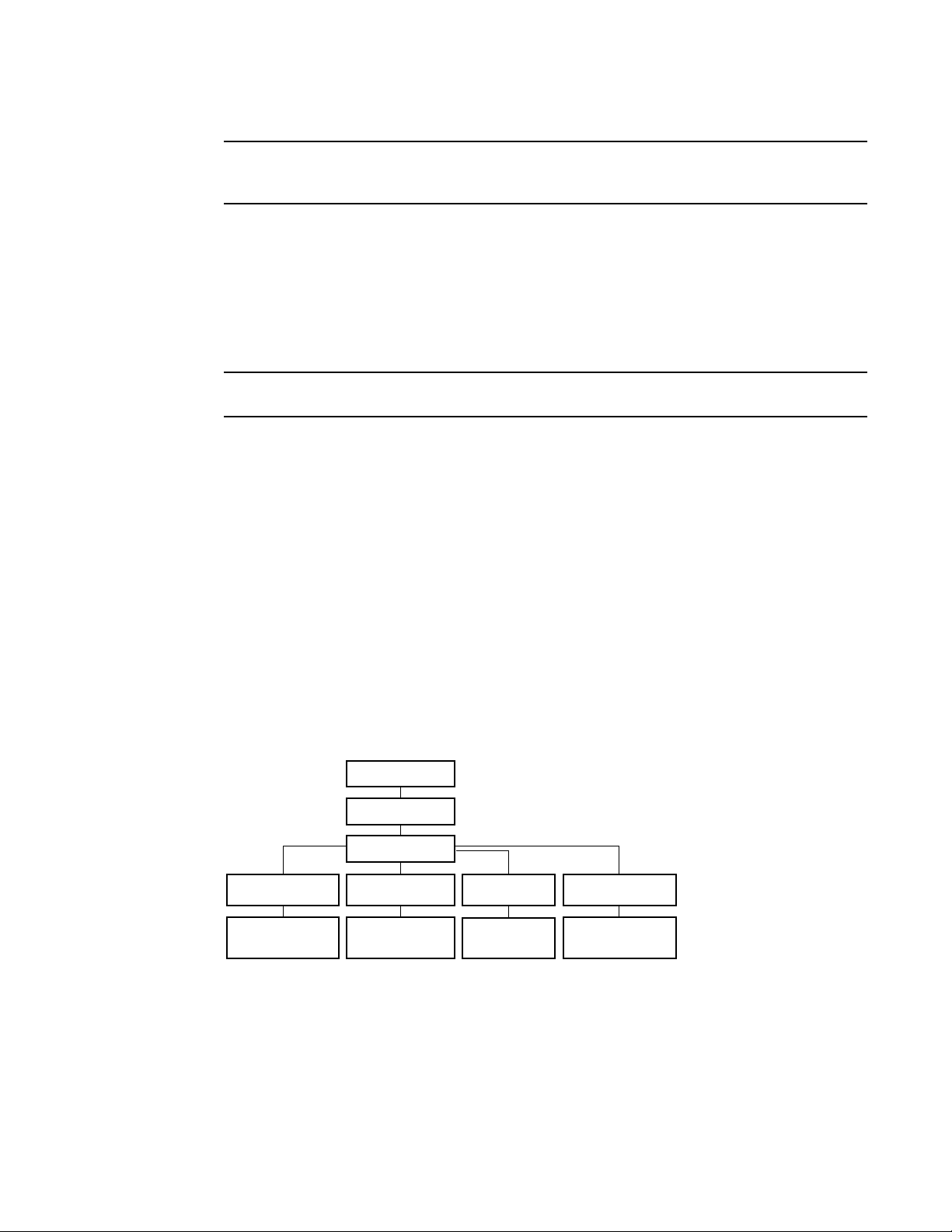
CEE CLI command modes
Figure 1 displays the CEE CLI command mode hierarchy.
FIGURE 1 CEE CLI command mode hierarchy
Tab le 3 lists the CEE CLI command modes and describes how to access them.
Converged Enhanced Ethernet Command Reference 3
53-1002164-01
Page 20

CEE command line interface
NOTE
1
At system startup, if you try to enter privileged EXEC mode before the system has fully booted, the
following message is displayed:
%Info: Please wait. System configuration is being loaded.
After the system has fully booted, a RASlog message indicates that the CEE CLI is ready to accept
configuration commands.
TABLE 3 CEE CLI command modes
Command
mode
EXEC switch> Enter the cmsh command at the
Privileged
EXEC
Global
configuration
Interface
configuration
Prompt How to access the command mode Description
Fabric OS prompt after you have
logged in as an appropriate user.
switch# From the EXEC mode, enter the
enable command.
switch(config)# From the EXEC mode, enter the
configure terminal EXEC command.
Port-channel:
switch(conf-if-po-63)#
10-Gigabit Ethernet (CEE port):
switch(conf-if-te-0/1)#
From the global configuration mode,
specify an interface by entering one
of the following commands:
• interface port-channel
• interface tengigabitethernet
• interface vlan
VLAN:
switch(conf-if-vl-1)#
Protocol
configuration
LLDP:
switch(conf-lldp)#
Spanning-tree:
switch(conf-mstp)#
switch(conf-rstp)#
switch(conf-stp)#
From the global configuration mode,
specify a protocol by entering one of
the following commands:
• protocol lldp
• protocol spanning-tree mstp
• protocol spanning-tree rstp
• protocol spanning-tree stp
Display running system information
and set terminal line parameters.
Display and change system
parameters. Note that this is the
administrative mode and also
includes EXEC mode commands.
Configure features that affect the
entire switch.
Access and configure individual
interfaces.
Access and configure protocols.
4 Converged Enhanced Ethernet Command Reference
53-1002164-01
Page 21

NOTE
TABLE 3 CEE CLI command modes (Continued)
CEE command line interface
1
Command
mode
Feature
configuration
Console and
VTY (line)
configuration
Prompt How to access the command mode Description
CEE map:
switch(config-ceemap)#
Standard ACL:
switch(conf-macl-std)#
Extended ACL:
switch(conf-macl-ext)#
switch(config-line)# From the global configuration mode,
From the global configuration mode,
specify a CEE feature by entering
one of the following commands:
• cee-map
• mac access-list
configure a terminal connected
through the console port by entering
the line console command.
Configure a terminal connected
through a Telnet session by entering
the line vty command.
Access and configure CEE features.
Identify traffic based on the MAC
addresses, such as VLAN IDs and
different encapsulations.
Standard Access Control Lists filter
the traffic on a source address and
block traffic close to a destination.
Extended Access Control Lists block
traffic based on any given packet
attribute.
Configure a terminal connected
through the console port or a
terminal connected through a Telnet
session.
After you apply the access list to an
interface, a Virtual Teletype (VTY), or
through a command using the
access list keyword, it becomes
effective.
Pressing Ctrl+Z or entering the end command in any mode returns you to privileged EXEC mode.
Entering exit in any mode returns you to the previous mode.
CEE CLI keyboard shortcuts
Tab le 4 lists CEE CLI keyboard shortcuts.
TABLE 4 CEE CLI keyboard shortcuts
Keystroke Description
Ctrl+B or the left arrow key Moves the cursor back one character.
Ctrl+F or the right arrow key Moves the cursor forward one character.
Ctrl+A Moves the cursor to the beginning of the command line.
Ctrl+E Moves the cursor to the end of the command line.
Esc B Moves the cursor back one word.
Esc F Moves the cursor forward one word.
Ctrl+Z Returns to privileged EXEC mode.
Ctrl+P or the up arrow key Displays commands in the history buffer with the most recent command
displayed first.
Ctrl+N or the down arrow key Displays commands in the history buffer with the most recent command
displayed last.
Converged Enhanced Ethernet Command Reference 5
53-1002164-01
Page 22

CEE command line interface
NOTE
1
In EXEC and privileged EXEC modes, use the show history command to list the commands most
recently entered. The switch retains the history of the last 1000 commands entered.
Using the do command as a shortcut
You can use the do command to save time when you are working in any configuration mode and
you want to run a command in EXEC or privileged EXEC mode.
For example, if you are configuring an LLDP and you want to execute a privileged EXEC mode
command, such as the dir command, you would first have to exit the LLDP configuration mode.
However, by using the do command with the dir command, you can ignore the need to change
configuration modes, as shown in the following example.
switch(conf-lldp)#do dir
Contents of flash://
-rw-r----- 1276 Wed Feb 4 07:08:49 2009 startup_rmon_config
-rw-r----- 1276 Wed Feb 4 07:10:30 2009 rmon_config
-rw-r----- 1276 Wed Feb 4 07:12:33 2009 rmon_configuration
-rw-r----- 1276 Wed Feb 4 10:48:59 2009 starup-config
Displaying CEE CLI commands and command syntax
Enter a question mark (?) in any command mode to display the list of commands available in that
mode.
switch>?
Exec commands:
enable Turn on privileged mode command
exit End current mode and down to previous mode
help Description of the interactive help system
logout Exit from the EXEC
quit Exit current mode and down to previous mode
show Show running system information
terminal Set terminal line parameters
To display a list of commands that start with the same characters, type the characters followed by
the question mark (?).
switch>e?
enable Turn on privileged mode command
exit End current mode and down to previous mode
To display the keywords and arguments associated with a command, enter the keyword followed by
the question mark (?).
switch#terminal ?
length Set number of lines on a screen
no Negate a command or set its defaults
If the question mark (?) is typed within an incomplete keyword, and the keyword is the only keyword
starting with those characters, the CLI displays help for that keyword only.
switch#show d?
dot1x IEEE 802.1X Port-Based Access Control
<cr>
6 Converged Enhanced Ethernet Command Reference
53-1002164-01
Page 23

CEE command line interface
1
If the question mark (?) is typed within an incomplete keyword but the keyword matches several
keywords, the CLI displays help for all the matching keywords.
switch#show i?
interface Interface status and configuration
ip Internet Protocol (IP)
The CEE CLI accepts abbreviations for commands. The following example is the abbreviation for the
show qos interface all command.
switch#sh q i a
If the switch does not recognize a command after Enter is pressed, an error message displays.
switch#hookup
^
% Invalid input detected at '^' marker.
If an incomplete command is entered, an error message displays.
switch#show
% Incomplete command.
CEE CLI command completion
To automatically complete the spelling of commands or keywords, begin typing the command or
keyword and then press Tab. For example, at the CLI command prompt, type te and press Tab:
switch#te
The CLI displays:
switch#terminal
If there is more than one command or keyword associated with the characters typed, the CEE CLI
displays all choices. For example, at the CLI command prompt, type show l and press Tab:
switch#show l
The CLI displays:
switch#show l
lacp line lldp
CEE CLI command output modifiers
You can filter the output of the CEE CLI show commands using the output modifiers described in
Tab le 5.
TABLE 5 CEE CLI command output modifiers
Output modifier Description
append Appends the output to a file.
redirect Redirects the command output to the specified file.
include Displays the command output that includes the specified expression.
exclude Displays the command output that excludes the specified expression.
append Appends the command output to the specified file.
begin Displays the command output that begins with the specified expression.
Converged Enhanced Ethernet Command Reference 7
53-1002164-01
Page 24

CEE command line interface
1
TABLE 5 CEE CLI command output modifiers (Continued)
Output modifier Description
last Displays only the last few lines of the command output.
tee Redirects the command output to the specified file. Note that this modifier also
displays the command output.
FLASH Redirects the output to flash memory.
8 Converged Enhanced Ethernet Command Reference
53-1002164-01
Page 25

Chapter
CEE Commands
advertise dcbx-fcoe-app-tlv
Advertises application Type, Length, Values (TLVs) to ensure interoperability of traffic over the Data
Center Bridging eXchange protocol (DCBX), which runs over LLDP to negotiate an FCoE application
TLV.
Synopsis advertise dcbx-fcoe-app-tlv
no advertise dcbx-fcoe-app-tlv
Operands None
Defaults Advertise is enabled.
Command
Modes
Description Use this command to advertise application TLVs to ensure interoperability of traffic over DCBX
Protocol LLDP configuration mode
packets. Converged Enhanced Ethernet (CEE) parameters related to FCoE must be negotiated
before FCoE traffic can begin on a CEE link. An FCoE application TLV is exchanged over LLDP, which
negotiates information such as FCoE priority, and Priority Flow Control (PFC) pause. Use the no
advertise dcbx-fcoe-app-tlv command to return to the default setting.
2
Usage
Guidelines
Examples None
See Also advertise dot1-tlv, advertise dot3-tlv, advertise optional-tlv
There are no usage guidelines for this command.
Converged Enhanced Ethernet Command Reference 9
53-1002164-01
Page 26

advertise dcbx-fcoe-logical-link-tlv
2
advertise dcbx-fcoe-logical-link-tlv
Advertises to any attached device the FCoE status of the logical link.
Synopsis advertise dcbx-fcoe-logical-link-tlv
no advertise dcbx-fcoe-logical-link-tlv
Operands None
Defaults Advertise is enabled.
Command
Modes
Description Use this command to advertise to any attached device the FCoE status of the logical link. Use the
Usage
Guidelines
Examples None
See Also advertise dcbx-fcoe-app-tlv, advertise dcbx-iscsi-app-tlv
Protocol LLDP configuration mode
no advertise dcbx-fcoe-logical-link-tlv command to return to the default setting.
There are no usage guidelines for this command.
10 Converged Enhanced Ethernet Command Reference
53-1002164-01
Page 27

advertise dcbx-iscsi-app-tlv
Advertises application Type, Length, Values (TLVs) to ensure interoperability of traffic over the Data
Center Bridging eXchange protocol (DCBX), which runs over LLDP to negotiate an iSCSI application
TLV.
Synopsis advertise dcbx-iscsi-app-tlv
no advertise dcbx-iscsi-app-tlv
Operands None
Defaults Advertise is enabled.
advertise dcbx-iscsi-app-tlv
2
Command
Modes
Description Use this command to advertise application TLVs to ensure interoperability of traffic over DCBX
Usage
Guidelines
Examples None
See Also advertise dcbx-fcoe-app-tlv
Protocol LLDP configuration mode
packets. Converged Enhanced Ethernet (CEE) parameters related to iSCSI must be negotiated
before iSCSI traffic can begin on a CEE link. An iSCSI application TLV is exchanged over LLDP, which
negotiates information such as iSCSI priority, and Priority Flow Control (PFC) pause. Use the no
advertise dcbx-iscsi-app-tlv command to return to the default setting.
There are no usage guidelines for this command.
Converged Enhanced Ethernet Command Reference 11
53-1002164-01
Page 28

advertise dcbx-tlv
2
advertise dcbx-tlv
Advertises to any attached device mandatory Data Center Bridging eXchange protocol (DCBX) Type,
Length, Values (TLVs).
Synopsis advertise dcbx-tlv
no advertise dcbx-tlv
Operands None
Defaults Advertise is enabled.
Command
Modes
Description Advertises to any attached device mandatory Data Center Bridging eXchange protocol (DCBX) Type,
Usage
Guidelines
Examples None
See Also advertise dot1-tlv, advertise dot3-tlv, advertise optional-tlv
Protocol LLDP configuration mode
Length, Values (TLVs). Use the no advertise dcbx-tlv command to return to the default setting.
There are no usage guidelines for this command.
12 Converged Enhanced Ethernet Command Reference
53-1002164-01
Page 29

advertise dot1-tlv
Advertises to any attached device IEEE 802.1 organizationally specific Type, Length, Value (TLV).
Synopsis advertise dot1-tlv
no advertise dot1-tlv
Operands None
Defaults Advertise is disabled.
advertise dot1-tlv
2
Command
Modes
Description Use this command to advertise to any attached device IEEE 802.1 organizationally specific Type,
Usage
Guidelines
Examples None
See Also advertise dot3-tlv, advertise dcbx-tlv, advertise optional-tlv
Protocol LLDP configuration mode
Length, Value (TLV). Use the no advertise dot1-tlv command to return to the default setting.
There are no usage guidelines for this command.
Converged Enhanced Ethernet Command Reference 13
53-1002164-01
Page 30

advertise dot3-tlv
2
advertise dot3-tlv
Advertises to any attached device IEEE 802.3 organizationally specific Type, Length, Value (TLV).
Synopsis advertise dot3-tlv
no advertise dot3-tlv
Operands None
Defaults Advertise is disabled.
Command
Modes
Description Use this command to advertise to any attached device IEEE 802.3 organizationally specific Type,
Usage
Guidelines
Examples None
See Also advertise dot1-tlv, advertise dcbx-tlv, advertise optional-tlv
Protocol LLDP configuration mode
Length, Value (TLV). Use the no advertise dot3-tlv command to return to the default setting.
There are no usage guidelines for this command.
14 Converged Enhanced Ethernet Command Reference
53-1002164-01
Page 31

advertise optional-tlv
Advertises the optional TLVs.
Synopsis advertise optional-tlv {management-address | port-description | system-capabilities |
system-description | system-name}
no advertise optional-tlv
Operands management-address
port-description Describes information about the interface. This includes the name of the
system-capabilities Describes the capabilities of the device and its primary function.
system-description Describes the system firmware version and the current image running on the
system-name Describes the name of the system. This value is defined by the system-name
advertise optional-tlv
Describes the MAC address or IP address of the switch.
manufacturer, the product name, and the version of the interface hardware
or software.
system. This value is defined by the system-description command.
command.
2
Defaults Advertise is enabled.
Command
Modes
Description Use this command to display the optional TLVs. Use the no advertise optional-tlv command to
Usage
Guidelines
Examples The following examples show how to advertise all of the options:
See Also system-description, system-name
Protocol LLDP configuration mode
return to the default setting.
There are no usage guidelines for this command.
switch(conf-lldp)#advertise optional-tlv management-address
switch(conf-lldp)#advertise optional-tlv port-description
switch(conf-lldp)#advertise optional-tlv system-capabilities
switch(conf-lldp)#advertise optional-tlv system-name
switch(conf-lldp)#advertise optional-tlv system-description
Converged Enhanced Ethernet Command Reference 15
53-1002164-01
Page 32

bridge-priority
2
bridge-priority
Synopsis bridge-priority priority
Operands priority Specifies the bridge priority. The range of valid values is from 0 through
Defaults The default priority is 32678.
Specifies the priority of the bridge.
no bridge-priority
61440.
Command
Modes
Description Use this command to set the bridge priority for the common instance. Using a lower priority value
Usage
Guidelines
Examples To specify the bridge priority:
See Also protocol spanning-tree
Protocol Spanning Tree mode
indicates that the bridge might become root. Use the no bridge-priority command to return to the
default settings.
This command must be used to specify the priority of the bridge. The priority values can be set only
in increments of 4096.
switch#configure terminal
switch(config)#protocol spanning-tree stp
switch(conf-stp)#bridge-priority 8192
16 Converged Enhanced Ethernet Command Reference
53-1002164-01
Page 33

cee
Applies the CEE map to an interface.
Synopsis cee default
no cee
Operands default The CEE map name.
Defaults The only map name allowed is “default”.
cee
2
Command
Modes
Description Applies the configured CEE map to the interface.
User Guidelines Use no cee to remove the map from the interface.
Examples Example of applying the CEE map to an interface.
See Also cee-map
Interface configuration mode
switch(config)#interface tengigabit 0/1
switch(conf-if-te-0/1)#cee default
Converged Enhanced Ethernet Command Reference 17
53-1002164-01
Page 34

cee-map
2
cee-map
Synopsis cee-map default
Operands default The CEE map name.
Defaults The only map name allowed is “default”.
Enters the CEE map configuration mode.
no cee-map
Command
Modes
Description Only a single CEE map is allowed, named “default”. It is created when the switch boots up.
Usage
Guidelines
Examples The initial configuration of the default CEE map is:
See Also cee, fcoe-map
Global configuration mode
Use no cee-map to revert to the default values for the map.
switch(config)#cee-map default
priority-group-table 2 weight 40 pfc
priority-group-table 3 weight 60
priority-table 2 2 2 1 2 2 2 2
18 Converged Enhanced Ethernet Command Reference
53-1002164-01
Page 35

channel-group
Synopsis channel-group number mode {active | passive | on} {type standard | brocade}
Operands number Specifies a Link Aggregation Group (LAG) port channel-group number to
Enables Link Aggregation on an interface.
no channel-group
which this link should administratively belong to. The range of valid values is
from 1 through 63.
mode Specifies the mode of Link Aggregation.
active Enables the initiation of LACP negotiation on an interface.
passive Disables LACP on an interface.
on Enables static link aggregation on an interface.
type Specifies the type of LAG.
standard Specifies the 802.3ad standard-based LAG.
brocade Specifies the Brocade proprietary hardware-based trunking.
channel-group
2
Defaults By default, the type is set to standard.
Command
Modes
Description Use this command to add an interface to a port-channel specified by the channel-group number.
Usage
Guidelines
Interface configuration mode
This command enables link aggregation on an interface, so that it may be selected for aggregation
by the local system. Use the no channel-group command to remove the port-channel members.
Only a maximum of 24 LAGs can be created. Note the following guidelines:
• A maximum of four link aggregation groups can be created per switch when the type is set to
brocade.
• A maximum of four links can become part of a single aggregation group when the type is set to
brocade and they must be on the same port-channel.
• Links 0 through 7 belong to port-channel 1; links 8 through 15 belong to port-channel 2, and
links 16 through 23 belong to port-channel 3.
• For the standard type, a maximum of 16 links can be aggregated per aggregation group and
they can be members of any port-channel.
Examples To set the channel-group number to 4 and the mode to active:
switch(conf-if)#channel-group 4 mode active
See Also interface
Converged Enhanced Ethernet Command Reference 19
53-1002164-01
Page 36

cisco-interoperability
2
cisco-interoperability
Configures the switch to interoperate with some legacy Cisco switches.
Synopsis cisco-interoperability {disable| enable}
Operands disable Disables Cisco interoperability for the Multiple Spanning Tree Protocol (MSTP)
enable Enables Cisco interoperability for the MSTP switch.
Defaults Cisco interoperability is disabled.
switch.
Command
Multiple Protocol Spanning Tree mode
Modes
Description Use this command to enable or disable the switch to interoperate with some legacy Cisco switches.
For some switches, the MSTP field Version 3 Length does not adhere to the current standards.
Usage
Guidelines
If Cisco interoperability is required on any switch in the network, then all switches in the network
must be compatible, and therefore enabled using this command for interoperability with a Cisco
switch.
Examples To enable Cisco interoperability on a switch:
switch#configure terminal
switch(config)#protocol spanning-tree mstp
switch(conf-mstp)#cisco-interoperability enable
To disable Cisco interoperability on a switch:
switch#configure terminal
switch(config)#protocol spanning-tree mstp
switch(conf-mstp)#cisco-interoperability disable
See Also None
20 Converged Enhanced Ethernet Command Reference
53-1002164-01
Page 37

clear counters
Synopsis clear counters {all | access-list mac access_list_name | {interface port-channel number |
Operands all Specifies to clear statistics on all interfaces.
clear counters
Clears statistics on one or all interfaces on the switch.
tengigabitethernet slot/port | slot}}
access-list mac access_list_name
Specifies the name of the MAC access list.
interface Use this keyword to specify any of the following interfaces:
port-channel number
Specifies the port-channel number. The range of valid values is from 1
through 63.
tengigabitethernet
Specifies a valid 10 Gbps Ethernet interface.
slot Specifies a valid slot number.
2
port Specifies a valid port number.
slot Specifies the slot number of the line card. For the Brocade 8000 switch, the
slot number is always 0 (zero).
Description Use this command to clear statistics on one or on all interfaces.
Command
Modes
Defaults There are no default configurations for this command.
User Guidelines The clear counters all command does not clear counters for any of the protocol daemon statistics,
Examples To clear the statistics for 10 Gbps Ethernet interface 0/1:
See Also show interface
Privileged EXEC mode
such as LLDP, LACP, MSTP, and so on.
switch#clear counters interface tengigabitethernet 0/1
To clear the statistics for the MAC access list named “test”:
switch#clear counters access-list mac test
Converged Enhanced Ethernet Command Reference 21
53-1002164-01
Page 38

clear counters access-list mac
2
clear counters access-list mac
Clears all the Media Access Control (MAC) access control list (ACL) counters for all interfaces that
have an ACL applied on them or for a specific interface.
Synopsis clear counters access-list mac name {interface |port-channel number | tengigabitethernet
slot/port | vlan vlan_id}
Operands. name Specifies the name of the MAC ACL.
interface tengigabitethernet
Specifies a valid 10 Gbps Ethernet interface.
slot Specifies a valid slot number.
port Specifies a valid port number.
port-channel number
Specifies the port-channel number. The range of valid values is from 1
through 63.
vlan vlan_id Specifies the VLAN number. The range of valid values is from 1 through 3583.
Defaults There are no default configurations for this command.
Command
Modes
Description Use this command to clear counters for all MAC ACL counters, or for a specific interface for the MAC
Usage
Guidelines
Examples To clear counters for the configured MAC ACL named test on an interface:
See Also show mac access-group, show statistics access-list mac
Privileged EXEC mode
ACL.
If the interface keyword is not specified, then ACL counters on all interfaces that have this ACL
applied are cleared. There are 255 ACL counters supported per port group.
switch#clear counters access-list mac test interface tengigabitethernet 0/1
To clear counters for the configured MAC access list named test on all interfaces on which this ACL
is applied:
switch#clear counters access-list mac test
22 Converged Enhanced Ethernet Command Reference
53-1002164-01
Page 39

clear dot1x statistics
Clears all 802.1X statistics.
Synopsis clear dot1x statistics
Operands None
Defaults There are no defaults for this command.
clear dot1x statistics
2
Command
Modes
Description Use this command to clear all accumulated port authentication statistics on all ports.
Usage
Guidelines
Examples To clear dot1x statistics:
See Also clear dot1x statistics interface
Privileged access mode
There are no usage guidelines for this command.
switch#clear dot1x statistics
Converged Enhanced Ethernet Command Reference 23
53-1002164-01
Page 40

clear dot1x statistics interface
2
clear dot1x statistics interface
Clears the 802.1X statistics for a port.
Synopsis clear dot1x statistics interface [tengigabitethernet slot/port]
Operands tengigabitethernet
slot Specifies a valid slot number.
port Specifies a valid port number.
Defaults There are no defaults for this command.
Specifies a valid 10 Gbps Ethernet interface.
Command
Modes
Description Use this command to clear all of the dot1x statistics for a specific interface port.
Usage
Guidelines
Examples To clear dot1x statistics on a port:
See Also clear dot1x statistics
Privileged access mode
There are no usage guidelines for this command.
switch#clear dot1x statistics interface tengigabitethernet 0/1
24 Converged Enhanced Ethernet Command Reference
53-1002164-01
Page 41

clear ip igmp group
Clears information related to learned groups in the IGMP module.
Synopsis clear ip igmp group {A.B.C.D {interface tengigabitethernet slot/port | interface port-channel
number | interface vlan vlan_id} | interface tengigabitethernet slot/port | interface port-channel
number | interface vlan vlan_id}
Operands A.B.C.D Specifies the group address, as a subnet number in dotted decimal format
interface tengigabitethernet
interface port-channel number
(for example, 10.0.0.1), as the allowable range of addresses included in the
multicast group.
Specifies a valid 10 Gbps Ethernet interface.
slot Specifies a valid slot number.
port Specifies a valid port number.
Specifies the interface is a port-channel. The range of valid values is from 1
through 63.
clear ip igmp group
2
interface vlan vlan_id
Specifies which VLAN interface to display the snooping configuration-related
information. The range of valid values is from 1 through 3583.
Defaults There are no defaults for this command.
Command
Modes
Description Use this command to clear the group information in the IGMP database, including entries for either
Usage
Guidelines
Examples To clear information for a learned group:
See Also None
Privileged EXEC mode
a specific group on all interfaces or specific groups on specific interfaces.
There are no usage guidelines for this command.
switch#clear ip igmp group 10.0.0.1 interface tengigabitethernet 0/1
Converged Enhanced Ethernet Command Reference 25
53-1002164-01
Page 42

clear ip igmp groups
2
clear ip igmp groups
Clears information related to learned groups in the IGMP protocol module.
Synopsis clear ip igmp groups
Operands None
Defaults There are no defaults for this command.
Command
Modes
Description Use this command to clear all IGMP group information in the IGMP database.
Usage
Guidelines
Examples To clear information for all groups in IGMP:
See Also None
Privileged EXEC mode
There are no usage guidelines for this command.
switch#clear ip igmp groups
26 Converged Enhanced Ethernet Command Reference
53-1002164-01
Page 43

clear lacp
Synopsis clear lacp number counters
Operands number Specifies the port channel-group number. The range of valid values is from 1
Defaults There are no default configurations for this command.
clear lacp
Clears the Link Aggregation Control Protocol (LACP) counters on a specific port-channel.
through 63.
counters Clears traffic counters.
2
Command
Modes
Description Use this command to clear the LACP counters per specified channel-group.
Usage
Guidelines
Examples To clear the LACP counters for a specific port-channel:
See Also show lacp counter
Privileged EXEC mode
There are no default configurations for this command.
switch#clear lacp 10 counters
Converged Enhanced Ethernet Command Reference 27
53-1002164-01
Page 44

clear lacp counters
2
clear lacp counters
Clears the Link Aggregation Control Protocol (LACP) counters on all port-channels.
Synopsis clear lacp counters
Operands None
Defaults There are no default configurations for this command.
Command
Modes
Description Use this command to clear the LACP counters for all port-channels.
Usage
Guidelines
Examples To clear the counters for all port-channels:
See Also show lacp counter
Privileged EXEC mode
There are no default configurations for this command.
switch#clear lacp counters
28 Converged Enhanced Ethernet Command Reference
53-1002164-01
Page 45

clear lldp neighbors
Clears the Link Layer Discovery Protocol (LLDP) neighbor information on all or specified interfaces.
Synopsis clear lldp neighbors [interface tengigabitethernet slot/port]
Operands interface tengigabitethernet
slot Specifies a valid slot number.
port Specifies a valid port number.
Defaults There are no default configurations for this command.
clear lldp neighbors
Specifies a valid 10 Gbps Ethernet interface for which to clear the LLDP
neighbor information.
2
Command
Modes
Description Use this command to clear the LLDP neighbor information about the devices learned through an
Usage
Guidelines
Examples To clear the LLDP neighbor information for all interfaces:
See Also show lldp statistics
Privileged EXEC mode
interface.
If the interface operand is not specified, this command clears the LLDP neighbor information
received on all the interfaces.
switch#clear lldp neighbors
To clear the LLDP neighbor information for a specific interface:
switch#clear lldp neighbors interface tengigabitethernet 0/1
Converged Enhanced Ethernet Command Reference 29
53-1002164-01
Page 46

clear lldp statistics
2
clear lldp statistics
Clears LLDP statistics for all interfaces or a specified interface.
Synopsis clear lldp statistics [interface tengigabitethernet slot/port]
Operands interface tengigabitethernet
Defaults There are no default configurations for this command.
Specifies a valid 10 Gbps Ethernet interface for which to clear the LLDP
statistics.
slot Specifies a valid slot number.
port Specifies a valid port number.
Command
Modes
Description Use this command to clear LLDP statistics for all interfaces or a specified interface.
Usage
Guidelines
Examples To clear all the LLDP statistics for all interfaces:
See Also show lldp neighbors
Privileged EXEC mode
If the interface operand is not specified, this command clears all the LLDP statistics on all
interfaces.
switch#clear lldp statistics
To clear all the LLDP statistics for a specific interface:
switch#clear lldp statistics interface tengigabitethernet 0/1
30 Converged Enhanced Ethernet Command Reference
53-1002164-01
Page 47

clear spanning-tree counter
Clears all spanning-tree counters on the interface.
Synopsis clear spanning-tree counter {interface| port-channel number | tengigabitethernet slot/port}
Operands interface Specifies the interface on which to clear the spanning-tree counters.
port-channel number
tengigabitethernet
slot Specifies a valid slot number.
port Specifies a valid port number.
Defaults There are no default configurations for this command.
clear spanning-tree counter
Specifies the port-channel number. The range of valid values is from 1
through 63.
Specifies a valid 10 Gbps Ethernet interface.
2
Command
Modes
Description Use this command to clear the spanning-tree counters on the interface.
Usage
Guidelines
Examples To clear spanning-tree counters for all interfaces:
See Also show spanning-tree
Privileged EXEC mode
If the interface operand is not specified, spanning-tree counters are cleared for all interfaces.
switch#clear spanning-tree counter
To clear spanning-tree counters for a 10 Gbps Ethernet interface:
switch#clear spanning-tree counter interface tengigabitethernet 0/1
To clear spanning-tree counters for port-channel 23:
switch#clear spanning-tree counter interface port-channel 23
Converged Enhanced Ethernet Command Reference 31
53-1002164-01
Page 48

2
copy
copy
Copies one file to another location.
Synopsis copy source-file-url destination-file-url
Operands source-file-url Specifies location of the source file to be copied using one of the following
formats:
flash Copies from URL [flash://]filename
FTP Copies from URL ftp://[username[:password]@server/path]
SCP Copies from URL scp://[username[:password]@server/path]
destination-file-url Specifies the destination file using one of the following formats:
flash Copies to URL [flash://]filename
FTP Copies to URL ftp://[username[:password]@server/path]
SCP Copies to URL scp://[username[:password]@server/path]
running-config Copies to the current running configuration.
startup--config Copies to the current startup configuration file.
Defaults There are no default values for this command.
Command
Modes
Description Use this command to copy a file to another location.
Usage
Guidelines
Privileged EXEC mode
The following guidelines apply when using this command:
• An error displays if there is no startup configuration file; for example:
switch #copy startup-config file2
% Error: No Startup-config.
• Use the write memory command to add entries in the startup configuration file.
• Use the write erase command to delete entries from the startup configuration file.
Examples To copy the source file to a remote machine using FTP:
switch#copy ftp://user@10.10.10.10/file1 file2
Source password[]?
To copy the source file from a remote machine using SCP:
switch#copy scp://user:password@10.10.10.10/file1 file2
To copy the source file from a local switch:
switch#copy flash://file1 file2
To copy the startup configuration file to the local switch:
switch#copy startup-config file2
Building configuration...
32 Converged Enhanced Ethernet Command Reference
53-1002164-01
Page 49

To copy the startup configuration file to a remote server through flash:
switch#copy startup-config flash://file2
Building configuration...
To copy the startup configuration file to a remote server through FTP:
switch#copy startup-config ftp://admin@10.10.10.10/file2
Source password[]?
Building configuration...
To copy the startup configuration file to a remote server through SCP:
switch#copy startup-config scp://admin@10.10.10.10/file2
Source password[]?
Building configuration...
See Also write erase
copy
2
Converged Enhanced Ethernet Command Reference 33
53-1002164-01
Page 50

debug ip igmp all
2
debug ip igmp all
Displays all IGMP information.
Synopsis debug ip igmp {all | group A.B.C.D | interface tengigabitethernet slot/port | interface port-channel
number| interface vlan vlan_id}
Operands all Displays all values.
group A.B.C.D Specifies the group address, as a subnet number in dotted decimal format
interface tengigabitethernet
interface port-channel number
(for example, 10.0.0.1), as the allowable range of addresses included in the
multicast group.
Specifies a valid 10 Gbps Ethernet interface.
slot Specifies a valid slot number.
port Specifies a valid port number.
Specifies the interface is a port-channel. The range of valid values is from 1
through 63.
interface vlan vlan_id
Specifies which VLAN interface to display the snooping configuration-related
information. The range of valid values is from 1 through 3583.
Defaults There are no defaults for this command.
Command
Modes
Description Displays all of the IGMP packets received and sent, and IGMP host-related events.
User Guidelines There are no user guidelines for this command.
Examples None
See Also None
Privileged EXEC mode
EXEC mode
34 Converged Enhanced Ethernet Command Reference
53-1002164-01
Page 51

debug lacp
Synopsis debug lacp {all | cli | event | nsm | pdu {rx all | rx interface tengigabitethernet slot/port} | tx all |
Operands all Turns on all debugging.
debug lacp
Enables debugging for the Link Aggregation Control Protocol (LACP).
tx interface tengigabitethernet slot/port}| sync | timer | trace level number}
no debug lacp {all | cli | event | nsm | pdu {rx all | rx interface tengigabitethernet slot/port} | tx all
| tx interface tengigabitethernet slot/port}| sync | timer | trace level number}
cli Turns on command line interface (CLI) debugging.
event Turns on event debugging.
nsm Turns on Network Services Module (NSM) debugging.
pdu Turns on protocol data unit (PDU) debugging.
rx all Turns on debugging for received LACP packets on all interfaces.
rx interface Turns on debugging for received LACP packets on the specified
interface.
2
interface tengigabitethernet
Specifies the 10 Gbps Ethernet interface.
slot Specifies the slot number.
port Specifies the port number.
tx all Turns on debugging for transmitted LACP packets on all interfaces.
tx interface Turns on debugging for transmitted LACP packets on the specified interface.
interface tengigabitethernet
Specifies the 10 Gbps Ethernet interface.
slot Specifies the slot number.
port Specifies the port number.
sync Turns on debugging for LACP sync transitions.
timer Turns on debugging for LACP timers.
trace level number Specifies the trace level number. The range of valid values is from 1 through
7.
Defaults By default, debugging is not turned on.
Command
Modes
Privileged EXEC mode
EXEC mode
Description Use this command to enable debugging for Link Aggregation Control Protocol (LACP). Use the no
debug command to disable debugging.
Usage
Guidelines
Converged Enhanced Ethernet Command Reference 35
53-1002164-01
To display debug outputs on a specific cmsh session, use the terminal monitor command.
Page 52

debug lacp
2
Examples To enable debugging of LACP PDUs for transmitted and received packets on all interfaces:
switch#debug lacp pdu tx all
switch#debug lacp pdu rx all
switch#show debug lacp
LACP rx debugging is on
LACP tx debugging is on
See Also show debug lacp
36 Converged Enhanced Ethernet Command Reference
53-1002164-01
Page 53

debug lldp packet
Enables debugging for Link Layer Discovery Protocol (LLDP).
Synopsis debug lldp packet {all | interface tengigabitethernet slot/port} {both | detail {both | rx | tx } | rx |
tx}
no debug lldp packet { all | interface tengigabitethernet slot/port }
Operands all Turns on LLDP packet debugging on all interfaces.
interface tengigabitethernet
debug lldp packet
Specifies the 10 Gbps Ethernet interface.
slot Specifies the slot number.
port Specifies the port number.
both Turns on debugging for both transmit and receive packets.
detail Turns on debugging with detailed information.
rx Turns on debugging for only received LLDP packets.
tx Turns on debugging for only transmitted LLDP packets.
2
Defaults By default, debugging is not turned on.
Command
Modes
Description Use this command to enable debugging for Link Layer Discovery Protocol (LLDP).
Usage
Guidelines
Examples To enable debugging of LLDP for both received and transmitted packets on 10 Gbps Ethernet
See Also show debug lldp
Privileged EXEC mode
EXEC mode
To display debugging outputs on a particular cmsh session, use the terminal monitor command.
Use the no debug lldp packet command to disable debugging.
interface 0/1:
switch#debug lldp packet interface tengigabitethernet 0/1 both
switch#show debug lldp
LLDP debugging status:
Interface te0/1 : Transmit Receive
Converged Enhanced Ethernet Command Reference 37
53-1002164-01
Page 54

debug spanning-tree
2
debug spanning-tree
Enables debugging for the Spanning Tree Protocol.
Synopsis debug spanning-tree {all | bpdu {rx | tx {all | interface port-channel number | interface
tengigabitethernet slot/port}}}
no debug spanning-tree {all | bpdu {rx | tx {all | interface port-channel number | interface
tengigabitethernet slot/port}}}
Operands all Turns on spanning-tree packet debugging on all interfaces.
bpdu Tu rns on Bridge Protocol Data Unit debugging.
rx Turns on debugging for only received spanning-tree packets.
tx Turns on debugging for only transmitted spanning-tree packets.
interface port-channel number
interface tengigabitethernet
Specifies the port-channel interface. The range of valid values is from 1
through 63.
Specifies the 10 Gbps Ethernet interface.
slot Specifies the slot number.
port Specifies the port number.
Defaults By default, debugging is not turned on.
Command
Modes
Privileged EXEC mode
EXEC mode
Description Use this command to enable debugging for the Spanning Tree Protocol.
Usage
Guidelines
To display debugging outputs on a particular cmsh session, use the terminal monitor command.
Use the no debug command to disable debugging.
Examples To enable debugging of spanning-tree packets for both Rx and Tx on 10 Gbps Ethernet interface
0/1:
switch#debug spanning-tree bpdu rx interface tengigabitethernet 0/1
switch#debug spanning-tree bpdu tx interface tengigabitethernet 0/1
switch#show debug spanning-tree
MSTP debugging status:
Spanning-tree rx debugging is off
Te 0/1 rx is on
Spanning-tree tx debugging is off
Te 0/1 tx is on
See Also show debug spanning-tree
38 Converged Enhanced Ethernet Command Reference
53-1002164-01
Page 55

delete
delete
2
Deletes a specified file from flash memory.
Synopsis delete filename
Operands filename Specifies the name of the file to be deleted from flash memory on the local
switch using the following format: [flash://]filename.
Defaults There is no default configuration for this command.
Command
Privileged EXEC mode
Modes
Description Use this command to delete a file from flash memory. After the file is deleted, it cannot be restored.
Usage
There are no usage guidelines for this command.
Guidelines
Examples To delete a file from flash memory:
switch#delete file1
% Warning: File will be deleted (from flash:)!
Continue?(y/n):y
or
switch#delete flash://file1
% Warning: File will be deleted (from flash:)!
Continue?(y/n):y
See Also copy
Converged Enhanced Ethernet Command Reference 39
53-1002164-01
Page 56

deny (extended ACLs)
2
deny (extended ACLs)
Configures a MAC address rule to drop traffic based on the source and destination MAC addresses.
Synopsis deny {any | host MAC _ACL| MAC_ACL} {any | host MAC _ACL| MAC _ACL} {EtherType | arp | fcoe
| ipv4} [count]
no deny {any | host MAC _ACL| MAC_ACL} {any | host MAC _ACL| MAC _ACL} {EtherType | arp |
fcoe | ipv4}
Operands any Specifies any source MAC address.
host MAC_ACL Specifies a host-specific source host MAC address for which to set deny
MAC_ACL Specifies any MAC address for which to set deny conditions. Use the format
any Specifies any destination MAC address.
host MAC_ACL Specifies a host-specific destination address for which to set deny conditions.
MAC_ACL Specifies any destination address for which to set deny conditions. Use the
conditions. Use the format HHHH.HHHH.HHHH.
HHHH.HHHH.HHHH.
Use the format HHHH.HHHH.HHHH.
format HHHH.HHHH.HHHH.
Ethertype Specifies the protocol number for which to set the deny conditions. The
range of valid values is from 1536 through 65535.
arp Specifies to deny the Address Resolution Protocol (0x0806).
fcoe Specifies to deny the Fibre Channel over Ethernet Protocol (0x8906).
ipv4 Specifies to deny the IPv4 protocol (0x0800).
count Enables counting of the packets matching the rule.
Defaults By default, no MAC ACLs are configured.
Command
Modes
Description Use this command to configure rules to match and drop traffic based on the source and
Usage
Guidelines
Examples To create a rule in an extended MAC ACL to drop IPv4 traffic from the source MAC address
Feature Access Control List configuration mode
destination MAC addresses and the protocol type. You can also enable counters for a specific rule.
There are 255 ACL counters supported per port group. Use the no deny command to remove a rule
from the MAC ACL.
The first set of {any |
address. The second set of {any | host MAC_ACL | MAC_ACL} parameters is specific to the
destination MAC address. The host MAC_ACL parameters is used for host sources only.
0022.3333.4444 to the destination MAC address 0022.3333.5555
of packets:
switch(conf-macl-ext)#deny 0022.3333.4444 0022.3333.5555 ipv4 count
host MAC_ACL | MAC_ACL} parameters is specific to the source MAC
and to enable the counting
40 Converged Enhanced Ethernet Command Reference
53-1002164-01
Page 57

To delete a rule from an extended MAC ACL:
switch(conf-macl-ext)#no deny 0022.3333.4444 0022.3333.5555 ipv4
See Also mac access-list extended, permit (extended ACLs)
deny (extended ACLs)
2
Converged Enhanced Ethernet Command Reference 41
53-1002164-01
Page 58

deny (standard ACLs)
2
deny (standard ACLs)
Configures a MAC address rule to drop traffic based on the source MAC address.
Synopsis deny {MAC_ACL | any} [count]
no deny {MAC_ACL | any}
Operands MAC_ACL Specifies the source host MAC address for which to set deny conditions. Use
any Specifies any source MAC address.
count Enables counting of the packets matching the rule.
Defaults By default, no MAC ACLs are configured.
the format HHHH.HHHH.HHHH.
Command
Modes
Description Use this command to configure rules to match and to drop traffic based on the source MAC
Usage
Guidelines
Examples To create a rule in a standard MAC ACL to drop traffic from the source MAC address
See Also mac access-list standard, permit (standard ACLs)
Feature Access Control List configuration mode
address. You can also enable counters for a specific rule. There are 255 ACL counters supported
per port group. Use the no deny command to remove a rule from the MAC ACL.
There are no usage guidelines for this command.
0022.3333.4444 and to enable the counting of packets:
switch(conf-macl-std)#deny 0022.3333.4444 count
To delete a rule from a standard MAC ACL:
switch(conf-macl-std)#no deny 0022.3333.4444
42 Converged Enhanced Ethernet Command Reference
53-1002164-01
Page 59

description (interface)
Specifies a string that contains the description of the interface.
Synopsis description line
no description
Operands line Specifies characters describing the interface. The maximum number of
Defaults There are no default configurations for this command.
characters is 64.
description (interface)
2
Command
Modes
Description Use this command to specify a string that contains the description of the interface. Use the no
Usage
Guidelines
Examples To set the string describing tengigabitethernet interface 0/1:
See Also None
Interface configuration mode
description command to remove the description.
There are no usage guidelines for this command.
switch(conf-if-te-0/1)#description converged_101
Converged Enhanced Ethernet Command Reference 43
53-1002164-01
Page 60

description (LLDP)
2
description (LLDP)
Specifies a string that contains the description of the LLDP.
Synopsis description line
no description
Operands line Characters describing LLDP.
Defaults There are no default configurations for this command.
Command
Modes
Description Use this command to specify a string that contains the description of the LLDP. Use the no
Usage
Guidelines
Examples To set the strings describing LLDP:
See Also None
Protocol LLDP configuration mode
description command to remove the description.
There are no usage guidelines for this command.
switch(conf-lldp)#description Brocade-LLDP
44 Converged Enhanced Ethernet Command Reference
53-1002164-01
Page 61

dir
Lists the contents of the current directory.
Synopsis dir
Operands None
Defaults The default is the current directory.
dir
2
Command
Modes
Privileged EXEC mode
EXEC mode
Description Use this command to list the contents of the current directory.
Usage
There are no usage guidelines for this command.
Guidelines
Examples To list the contents of the current directory:
switch#dir
Contents of flash://
-rw-r----- 1276 Wed Feb 4 07:08:49 2009 startup_rmon_config
-rw-r----- 1276 Wed Feb 4 07:10:30 2009 rmon_config
-rw-r----- 1276 Wed Feb 4 07:12:33 2009 rmon_configuration
-rw-r----- 1276 Wed Feb 4 10:18:15 2009 starup-config
See Also delete
Converged Enhanced Ethernet Command Reference 45
53-1002164-01
Page 62

2
disable
Synopsis disable
Operands None
disable
Exits the privileged EXEC mode and returns to the EXEC mode.
Defaults There are no default configurations for this command.
Command
Modes
Description Use this command to exit the privileged EXEC mode and return to the EXEC mode. See “CEE CLI
Usage
Guidelines
Examples To return to the EXEC mode:
See Also enable, end, exit, quit
Privileged EXEC mode
command modes” on page 3.
This is the only command that allows you to return to the EXEC mode. Using the exit or quit
commands from the privileged EXEC mode ends the session instead of returning to the EXEC
mode.
switch#disable
switch>
46 Converged Enhanced Ethernet Command Reference
53-1002164-01
Page 63

do
Allows you to run commands in EXEC mode from the configuration mode.
Synopsis do command
Operands command Specifies the command you want to run.
Defaults There are no default configurations for this command.
do
2
Command
All configuration modes
Modes
Description Use this command to save time when you are configuring the switch in any configuration mode and
you want to run a command in the privileged EXEC mode.
Usage
There are no usage guidelines for this command.
Guidelines
Examples To r u n t h e clear counters all command with the do command:
switch(config)#do clear counters all
To display the contents from the working directory using the do command:
switch(config)#do dir
Contents of flash://
-rw-r----- 1276 Wed Feb 4 07:08:49 2009 startup_rmon_config
-rw-r----- 1276 Wed Feb 4 07:10:30 2009 rmon_config
-rw-r----- 1276 Wed Feb 4 07:12:33 2009 rmon_configuration
-rw-r----- 1276 Wed Feb 4 10:48:59 2009 starup-config
See Also None
Converged Enhanced Ethernet Command Reference 47
53-1002164-01
Page 64

dot1x authentication
2
dot1x authentication
Enables 802.1X on a port.
Synopsis dot1x authentication
no dot1x authentication
Operands None
Defaults There are no defaults for this command.
Command
Modes
Description Use this command to enable dot1x on a port. Use the no dot1x authentication command to disable
Usage
Guidelines
Examples To e n a b le dot1x on a port:
See Also None
Interface configuration mode
dot1x on the port and remove the configuration from 802.1X management.
There are no usage guidelines for this command.
switch(config)#interface tengigabitethernet 0/1
switch(conf-if-te-0/1)#dot1x authentication
48 Converged Enhanced Ethernet Command Reference
53-1002164-01
Page 65

dot1x enable
Synopsis dot1x enable
Operands None
Defaults By default, authentication is disabled globally.
Enables 802.1X authentication globally.
no dot1x enable
dot1x enable
2
Command
Modes
Description Use this command to enable 802.1X. Use the no dot1x enable command to disable 802.1X
Usage
Guidelines
Examples To enable 802.1X authentication globally:
See Also None
Global configuration mode
authentication globally.
There are no usage guidelines for this command.
switch(config)#dot1x enable
Converged Enhanced Ethernet Command Reference 49
53-1002164-01
Page 66

dot1x port-control
2
dot1x port-control
Controls the authorization of a port state.
Synopsis dot1x port-control {auto | force-authorized | force-unauthorized}
no dot1x port-control
Operands auto Enables authentication on a port.
forced-authorized Forces a port to remain in an authorized state.
force-unauthorized
Defaults The default port state is auto.
Forces a port to remain in an unauthorized state.
Command
Modes
Description Use this command to control the authorization of a port state. Use the no dot1x port-control
Usage
Guidelines
Examples To enable the port state to auto:
See Also None
Interface configuration mode
command to return to the default setting.
There are no usage guidelines for this command.
switch(config)#interface tengigabitethernet 0/1
switch(conf-if-te-0/1)#dot1x port-control auto
50 Converged Enhanced Ethernet Command Reference
53-1002164-01
Page 67

dot1x protocol-version
Sets the Extensible Authentication Protocol over LANs (EAPOL) version for 802.1x.
Synopsis dot1x protocol-version version_value
Operands version_value Defines the EAPOL version. The range of valid values is from 1 through 2.
Defaults The default EAPOL version is 2.
dot1x protocol-version
2
Command
Modes
Description This commands sets the EAPOL version for 802.1x for the interface. There is little difference
User Guidelines 802.1x must be configured for the interface before executing this command.
Examples None
See Also None
Interface configuration mode
between version 1 and version 2. You should probably leave it set to version 2 unless you are
having a specific issue.
Converged Enhanced Ethernet Command Reference 51
53-1002164-01
Page 68

dot1x quiet-period
2
dot1x quiet-period
Sets the number of seconds that a switch remains quiet between a failed authentication and an
attempt to retry authentication.
Synopsis dot1x quiet-period interval seconds
no dot1x quiet-period
Operands interval seconds Specifies the time in seconds between attempts at authentication. The range
Defaults The default time is 60 seconds.
of valid values is from 1 through 65535.
Command
Modes
Description Use this command to set the time in seconds after which a switch attempts to perform
Usage
Guidelines
Examples To change the interval time to 200 seconds:
See Also None
Interface configuration mode
authentication after a failed authentication. Use the no dot1x quiet-period command to return to
the default setting. When a switch cannot authenticate a client, the switch remains idle for a
quiet-period interval of time, then attempts the operation again.
Changing the quiet-period interval time to a number lower than the default can result in a faster
response time.
switch(config)#interface tengigabiethernet 0/1
switch(conf-if-te-0/1)#dot1x quiet-period 200
52 Converged Enhanced Ethernet Command Reference
53-1002164-01
Page 69

dot1x reauthenticate interface
Initiates reauthentication on a specified interface.
Synopsis dot1x reauthenticate interface name
Operands name Specifies the name of the interface.
Defaults There are no defaults for this command.
dot1x reauthenticate interface
2
Command
Modes
Description Use this command to initiate the reauthentication on a specified interface.
Usage
Guidelines
Examples To initiate reauthentication on interface tengigabitethernet 0/1:
See Also None
Privileged EXEC mode
There are no usage guidelines for this command.
switch#dot1x reauthenticate interface tengigabitethernet 0/1
Converged Enhanced Ethernet Command Reference 53
53-1002164-01
Page 70

dot1x reauthentication
2
dot1x reauthentication
Enables reauthentication on a port.
Synopsis dot1x reauthentication
Operands None
Defaults There are no defaults for this command.
Command
Modes
Description Use this command to enable reauthentication on a port.
Usage
Guidelines
Examples To enable reauthentication on a port:
See Also None
Interface configuration mode
There are no usage guidelines for this command.
switch(config)#interface tengigabitethernet 0/1
switch(conf-if-te-0/1)#dot1x reauthentication
54 Converged Enhanced Ethernet Command Reference
53-1002164-01
Page 71

dot1x reauthMax
Sets the maximum number of times that a port attempts to reauthenticate.
Synopsis dot1x reauthMax number
no dot1x reauthMax
Operands number Specifies the maximum number of reauthentication attempts before the port
Defaults The default number of times that a port attempts authentication is 2.
dot1x reauthMax
goes to the unauthorized state. The range of valid values is from 1 through
10.
2
Command
Modes
Description Use this command to set the maximum number of times that a port attempts to reauthenticate
Usage
Guidelines
Examples To set the maximum number of reauthentication attempts to 5:
See Also None
Interface configuration mode
before a port changes to the unauthorized state. Use the no dot1x reauthMax command to return
to the default setting.
There are no usage guidelines for this command.
switch(config)#interface tengigabitethernet 0/1
switch(conf-if-te-0/1)#dot1x reauthMax 5
To set the reauthentication maximum to the default value:
switch(config)#interface tengigabitethernet 0/1
switch(conf-if-te-0/1)#no dot1x reauthMax
Converged Enhanced Ethernet Command Reference 55
53-1002164-01
Page 72

dot1x timeout re-authperiod
2
dot1x timeout re-authperiod
Sets the number of seconds between reauthorization attempts.
Synopsis dot1x timeout re-authperiod seconds
Operands seconds Specifies the seconds between reauthorization attempts. The range of valid
Defaults The default time is 3600 seconds.
values is from 1 through 4294967295.
Command
Modes
Description Use this command to set the number of seconds between reauthorization attempts.
Usage
Guidelines
Examples To set 25 seconds as the amount of time between reauthorization attempts:
See Also None
Interface configuration mode
There are no usage guidelines for this command.
switch(config)#interface tengigabitethernet 0/1
switch(conf-if-te-0/1)#dot1x timeout re-authperiod 25
56 Converged Enhanced Ethernet Command Reference
53-1002164-01
Page 73

dot1x timeout server-timeout
Sets the authentication server response timeout.
Synopsis dot1x timeout server-timeout seconds
Operands seconds Specifies the number of seconds that a switch waits for the transmission of
Defaults The default timeout is 30 seconds.
dot1x timeout server-timeout
packets by the switch to the authentication server. The range of valid values
is from 1 through 65535.
2
Command
Modes
Description Use this command to set the authentication server response timeout.
Usage
Guidelines
Examples To set 40 seconds as the switch-to-authentication server transmission time:
See Also None
Interface configuration mode
There are no usage guidelines for this command.
switch(config)#interface tengigabitethernet 0/1
switch(config-if)#dot1x timeout server-timeout 40
Converged Enhanced Ethernet Command Reference 57
53-1002164-01
Page 74

dot1x timeout supp-timeout
2
dot1x timeout supp-timeout
Sets the time in seconds that a switch waits for a response to an Extensible Authentication Protocol
(EAP) request frame from the client before resending the request.
Synopsis dot1x timeout supp-timeout seconds
Operands seconds Specifies the number of seconds that the switch waits for a response to the
Defaults The default timeout is 30 seconds.
EAP frame. The range of valid values is from 1 through 65535.
Command
Modes
Description Use this command to specify the EAP response timeout.
Usage
Guidelines
Examples To set 40 seconds as the switch-to-client retransmission time for the EAP request frame:
See Also None
Interface configuration mode
There are no usage guidelines for this command.
switch(conf-if-te-0/1)#dot1x timeout supp-timeout 40
58 Converged Enhanced Ethernet Command Reference
53-1002164-01
Page 75

dot1x timeout tx-period
Sets the number of seconds that the switch waits for a response to an Extensible Authentication
Protocol (EAP) request or identity frame from the client before retransmitting the request.
Synopsis dot1x timeout tx-period seconds
Operands seconds Specifies the time in seconds between successive request ID attempts. The
Defaults The default timeout is 30 seconds.
dot1x timeout tx-period
range of valid values is from 1 through 65535.
2
Command
Modes
Description Use this command to set the interval between successive attempts to request an ID (EAP ID Req).
Usage
Guidelines
Examples To set 34 as the number of seconds to wait for a response to an EAP request or identity frame from
See Also None
Interface configuration mode
There are no usage guidelines for this command.
the client before retransmitting the request:
switch(config)#interface tengigabitethernet 0/1
switch(config-if)#dot1x timeout tx-period 34
Converged Enhanced Ethernet Command Reference 59
53-1002164-01
Page 76

2
enable
Operands None
enable
Enables the Privilege EXEC mode.
Synopsis enable
Defaults There are no default configurations for this command.
Command
Modes
Description Use this command to enable the privileged EXEC command mode.
Usage
Guidelines
Examples To enable the privileged EXEC mode:
See Also disable
EXEC mode
To return to the EXEC mode from privileged EXEC mode, use the disable command. Using the exit
or quit command from the privileged EXEC mode ends the session. See “CEE CLI command modes”
on page 3.
switch> enable
switch#
60 Converged Enhanced Ethernet Command Reference
53-1002164-01
Page 77

end
Returns to the privileged EXEC command mode from all configuration modes.
Synopsis end
Operands None
Defaults There are no default configurations for this command.
end
2
Command
Modes
Description Use this command to return to the privileged EXEC command mode from any command mode. See
Usage
Guidelines
Examples To return to the privileged EXEC mode from interface configuration mode:
See Also disable, enable, exit
All configuration modes
“CEE CLI command modes” on page 3.
There are no usage guidelines for this command.
switch(config)#interface tengigabitethernet 0/0
switch(conf-if-te-0/0)#end
switch#
Converged Enhanced Ethernet Command Reference 61
53-1002164-01
Page 78

erase flash
2
erase flash
Synopsis erase flash
Operands None
Defaults There are no default configurations for this command.
Erases all the files from flash memory.
Command
Modes
Description Use this command to erase the files from flash memory.
Usage
Guidelines
Examples To erase the files from flash memory:
See Also dir, delete
EXEC mode
There are no usage guidelines for this command.
switch#erase flash
%% Warning: Erasing flash filesystem will remove all files in flash://.
Continue to erase?(y/n):y
switch#
62 Converged Enhanced Ethernet Command Reference
53-1002164-01
Page 79

error-disable-timeout enable
Enables the timer to bring the interface out of the error-disabled state.
Synopsis error-disable-timeout enable
Operands None
Defaults There are no default configurations for this command.
error-disable-timeout enable
2
Command
Modes
Description Use this command to enable the timer to bring the interface out of the disabled state.
Usage
Guidelines
Examples To bring the interface out of the disabled state:
See Also error-disable-timeout interval
Spanning Tree Protocol configuration mode
When the Spanning Tree Protocol (STP) Bridge Protocol Data Unit (BPDU) guard disables a port, the
port remains in the disabled state unless the port is enabled manually. This command allows you
to enable the interface from the disabled state.
switch(conf-rstp)#error-disable-timeout enable
Converged Enhanced Ethernet Command Reference 63
53-1002164-01
Page 80

error-disable-timeout interval
2
error-disable-timeout interval
Sets the interface to time out when an error occurs.
Synopsis error-disable-timeout interval seconds
Operands seconds Specifies the range of time in seconds for the interface to time out. The range
Defaults The default is 300 seconds. The timeout feature is disabled.
of valid values is from 10 through 1000000.
Command
Modes
Description Use this command to set the interface to time out when an error occurs.
Usage
Guidelines
Examples To set the timeout value to 10 seconds:
See Also error-disable-timeout enable
Spanning Tree Protocol configuration mode
There are no usage guidelines for this command.
switch(conf-rstp)#error-disable-timeout interval 10
64 Converged Enhanced Ethernet Command Reference
53-1002164-01
Page 81

exec-timeout
Synopsis exec-timeout minutes seconds
Operands minutes Specifies the time interval in minutes. The range is from 0 through 35791.
Defaults The default is 10 minutes.
exec-timeout
Sets the interval that the EXEC command interpreter waits for user input.
no exec-timeout
seconds Specifies the time interval in seconds. The range is from 0 through 2147483.
2
Command
Modes
Description Use this command to set the interval; the command interpreter waits for user input detected. Use
Usage
Guidelines
Examples To configure the wait interval for the console session:
See Also line console, line vty, show line
Console and VTY (line) configuration mode
no exec-timeout to disable the wait interval that the command interpreter waits.
The exec-timeout command is used to set the time the Telnet session waits for an idle VTY session,
before it time outs. An exec-timeout setting of 0 (zero) causes the Telnet session to wait indefinitely.
switch(config)#line console 0
switch(conf-line)#exec-timeout 2 30
switch(config)#line vty 0 9
switch(conf-line)#exec-timeout 30 30
Converged Enhanced Ethernet Command Reference 65
53-1002164-01
Page 82

2
exit
exit
Exits the current mode and returns to the previous mode.
Synopsis exit
Operands None
Defaults There are no default configurations for this command.
Command
Modes
Description Use this command to exit the current mode, and return to the previous mode. When used in EXEC
Usage
Guidelines
Examples To exit the Interface configuration mode, and return to the global configuration mode:
See Also disable, enable, end
All command modes
and privileged EXEC modes, the exit command terminates the session. See “CEE CLI command
modes” on page 3.
There are no usage guidelines for this command.
switch(config)#interface tengigabitethernet 0/0
switch(conf-if-te-0/0)#exit
switch(config)#exit
66 Converged Enhanced Ethernet Command Reference
53-1002164-01
Page 83

fcoe-map
Synopsis fcoe-map default
Operands default The FCoE map name.
Defaults The only map name allowed is “default”.
Activates the FCoE map configuration mode.
fcoe-map
2
Command
Modes
Description Only a single FCoE map is allowed, named “default”.
User Guidelines There are no usage guidelines for this command.
Examples To activate the FCoE map:
See Also cee-map, fcoeport, fcoe-vlan
Global configuration mode
If you do not execute the fcoe-vlan command first, VLAN 1002 is created automatically and
becomes the FCoE VLAN. If VLAN 1002 already exists, it is modified to become the FCoE VLAN.
switch(config)#fcoe-map default
fcoe-map : default
fcoe-vlan : 1002
Converged Enhanced Ethernet Command Reference 67
53-1002164-01
Page 84

fcoeport
2
fcoeport
Synopsis fcoeport
Operands None
Defaults There are no default configurations for this command.
Applies the FCoE map to an interface.
Command
Modes
Description Use this command to apply the FCoE map to an interface. You must be in interface configuration
User Guidelines There are no usage guidelines for this command.
Examples To enter interface configuration mode and then apply the FCoE map:
See Also cee-map, fcoe-map, fcoe-vlan
Interface configuration mode
mode for a selected interface.
This command makes the interface FCoE-capable. The CEE map is added to the interface, and if
the interface is CEE-capable, the FCoE VLAN is added to the interface.
switch(config)#interface tengigabitethernet 0/20
switch(conf-if-te-0/20)#fcoeport
68 Converged Enhanced Ethernet Command Reference
53-1002164-01
Page 85

fcoe-priority-bits
Synopsis fcoe-priority-bits {none | list value_1 | value_2 | value_3 | value_4 | value_5 | value_6 | value_7
Operands none Removes all priority bits.
fcoe-priority-bits
Sets the FCoE priority bit for LLDP.
| value_8}
list List the FCoE priorities for LLDP.
value_1 The first CoS value. The range of valid values is from 0 through 7.
value_2 The second CoS value. The range of valid values is from 0 through 7.
value_3 The third CoS value. The range of valid values is from 0 through 7.
value_4 The fourth CoS value. The range of valid values is from 0 through 7.
value_5 The fifth CoS value. The range of valid values is from 0 through 7.
value_6 The sixth CoS value. The range of valid values is from 0 through 7.
value_7 The seventh CoS value. The range of valid values is from 0 through 7.
2
value_8 The eighth CoS value. The range of valid values is from 0 through 7.
Defaults The default list value is 3.
Command
Modes
Description The FCoE priority bit setting is a bitmap setting where each bit position stands for a priority. When
User Guidelines Though setting multiple bits is allowed (exercising the full range of values), there is no reason to set
Examples The following example sets the first CoS value:
See Also lldp fcoe-priority-bits
Protocol LLDP configuration mode
you set a bit for a particular priority, that priority setting is applied to the FCoE traffic (that is, the
incoming FCoE traffic will have that priority).
FCoE traffic is only supported on the priority level that also has flow control enabled. This means
that the final advertised FCoE priority consists of the configured FCoE priority setting and the
per-priority flow control setting.
more than one bit because the adapters do not support multiple priorities for FCoE.
switch(conf-lldp)#fcoe-priority-bits list 0
Converged Enhanced Ethernet Command Reference 69
53-1002164-01
Page 86

fcoe-vlan
2
fcoe-vlan
Synopsis fcoe-vlan vlan_id
Operands vlan_id Specifies the VLAN interface. The range of valid values is from 2 through
Defaults The default VLAN is 1002.
Configures an FCoE VLAN to the FCoE map and deletes the previous FCoE VLAN.
3583.
Command
Modes
Description Use this command to configure an FCoE VLAN to the FCoE map. Using this command deletes the
User Guidelines There are no usage guidelines for this command.
Examples You must first enter FCoE map mode, then configure the VLAN:
See Also cee-map, fcoeport
Feature configuration mode
previous FCoE VLAN.
switch(config)#fcoe-map default
switch(conf-fcoe-map)#fcoe-vlan 1002
70 Converged Enhanced Ethernet Command Reference
53-1002164-01
Page 87

forward-delay
Synopsis forward-delay seconds
Operands seconds Specifies the range of time in seconds that an interface spends in the
Defaults The default is 15 seconds.
forward-delay
Specifies the time an interface spends in each of the listening and learning states.
no forward-delay
Spanning Tree Protocol (STP) learning and listening states. The range of valid
values is from 4 through 30.
2
Command
Modes
Description Use this command to specify how long the listening and learning states last before the interface
Usage
Guidelines
Spanning Tree Protocol configuration mode
begins the forwarding of all spanning-tree instances. Use the no forward-delay command to return
to the default settings.
STP interface states:
• Listening - The interface processes the Bridge Protocol Data Units (BPDUs) and awaits possible
new information that might cause it to return to the blocking state.
• Learning - The interface does not yet forward frames (packets). Instead it learns source
addresses from frames received and adds them to the filtering database (switching database).
• Forwarding - An interface receiving and sending data (normal operation). STP still monitors
incoming BPDUs that can indicate it should return to the blocking state to prevent a loop.
• Blocking - An interface that can cause a switching loop (no user data is sent or received), but it
might go to the forwarding state if the other links in use fail and the STP determines that the
interface may transition to the forwarding state. BPDU data continues to be received in the
blocking state.
When you change the spanning-tree forward-delay time, it affects all spanning-tree instances.
When configuring the forward-delay, the following relationship should be kept:
2*(forward-delay - 1)>=max-age>=2*(hello-time + 1)
Examples To configure the forward-delay time to 18 seconds:
switch(conf-mstp)#forward-delay 18
See Also hello-time, max-age, max-hops
Converged Enhanced Ethernet Command Reference 71
53-1002164-01
Page 88

2
fos
fos
Executes Fabric OS commands from the from the cmsh shell.
Synopsis fos command
Operands command Specifies the Fabric OS command.
Defaults There are no default configurations for this command.
Command
Modes
Description Use this command to execute the following Fabric OS commands from the cmsh shell.
Privileged EXEC mode
alishow
cfgactvshow
cfgshow
errclear
errshow
fabricshow
fcoe
firmwareshow
ipaddrshow
nsallshow
nscamshow
nsshow
portcfg
portcfgshow
portdisable
portenable
porterrshow
portlogshow
portperfshow
portrouteshow
portstatsclear
portstatsshow
slotpoweroff
slotpoweron
slotshow
72 Converged Enhanced Ethernet Command Reference
53-1002164-01
Page 89

supportsave
switchshow
zoneshow
fos
2
Usage
Guidelines
The Fabric OS syntax applies to the listed commands. The fcoelogincfg, fcoelogingroup, and
fcoelogincfg commands are not supported from the cmsh shell. See the Fabric OS Command
Reference for additional information on these commands.
Examples To r u n t h e Fabric OS com m a n d switchshow from the Privilege EXEC mode:
switch#fos switchshow
switchName: switch
switchType: 76.6
switchState: Online
switchMode: Native
switchRole: Principal
switchDomain: 1
switchId: fffc01
switchWwn: 10:00:00:05:1e:76:42:00
zoning: OFF
switchBeacon: OFF
Area Port Media Speed State Proto
=====================================
0 0 -- N8 No_Module FC
1 1 -- N8 No_Module FC
2 2 -- N8 No_Module FC
3 3 -- N8 No_Module FC
4 4 -- N8 No_Module FC
5 5 -- N8 No_Module FC
6 6 -- N8 No_Module FC
7 7 -- N8 No_Module FC
8 8 -- 10 Online FCoE F-Port 20:08:00:05:1e:76:42:00
9 9 -- 10 Online FCoE F-Port 20:09:00:05:1e:76:42:00
10 10 -- 10 Online FCoE F-Port 20:0a:00:05:1e:76:42:00
11 11 -- 10 Online FCoE F-Port 20:0b:00:05:1e:76:42:00
12 12 -- 10 Online FCoE F-Port 20:0c:00:05:1e:76:42:00
13 13 -- 10 Online FCoE F-Port 20:0d:00:05:1e:76:42:00
See Also None
Converged Enhanced Ethernet Command Reference 73
53-1002164-01
Page 90

2
hello
hello
Sets the Hello transmit interval.
Synopsis hello seconds
no hello
Operands seconds Sets the Hello transmit interval. The range of valid values is from 4 through
180 seconds.
Defaults The default is 30 seconds.
Command
Modes
Description Use this command to set the interval between LLDP hello messages. Use the no hello command to
Usage
Guidelines
Examples To set the time interval to 10 seconds between the transmissions:
See Also None
Protocol LLDP configuration mode
return to the default setting.
There are no usage guidelines for this command.
switch(conf-lldp)#hello 10
74 Converged Enhanced Ethernet Command Reference
53-1002164-01
Page 91

hello-time
Synopsis hello-time seconds
Operands seconds Specifies the time range in seconds for the interval between the hello BPDUs
Defaults The default is 2 seconds.
hello-time
Sets the interval between the hello Bridge Protocol Data Units (BPDUs) sent on an interface.
no hello-time
sent on an interface. The range of valid values is from 1 through 10.
2
Command
Modes
Description Use this command to configure the spanning-tree bridge hello time, which determines how often
Usage
Guidelines
Examples To configure the spanning-tree bridge hello time to 5 seconds:
See Also forward-delay, max-age
Spanning Tree Protocol configuration mode
the device broadcasts hello messages to other devices. Use the no hello-time command to return
to the default settings.
When configuring the hello-time, the max-age setting must be greater than the hello-time setting.
The following relationship should be kept:
2*(forward-delay - 1)>=max-age>=2*(hello-time + 1)
switch(conf-stp)#hello-time 5
Converged Enhanced Ethernet Command Reference 75
53-1002164-01
Page 92

instance
2
instance
Synopsis instance instance_id {vlan vlan_id | priority priority_id}
Operands instance_id Specifies the MSTP instance. The range of valid values is from 1 through 15.
Defaults The default priority value is 32768.
Maps a VLAN to a Multiple Spanning Tree Protocol (MSTP) instance.
no instance
vlan vlan_id Specifies the VLAN to map to an MSTP instance. The range of valid values is
from 1 through 3583.
priority priority_id
Specifies the priority for the specified instance. The range of valid values is
from 0 through 61440. The priority values can be set only in increments of
4096.
Command
Modes
Description Use this command to map a VLAN to an MTSP instance. You can group a set of VLANs to an
Usage
Guidelines
Multiple Spanning Tree Protocol configuration mode
instance. This command can be used only after the VLAN is defined. Use the no instance command
to unmap the VLAN from the MSTP instance.
The following rules apply:
• VLANs must be created before mapping to instances.
• VLAN instance mapping is removed from the configuration if the underlying VLANs are deleted.
Examples To map a VLAN to an MTSP instance:
switch(conf-mstp)#instance 1 vlan 2, 3
switch(conf-mstp)#instance 2 vlan 4-6
switch(conf-mstp)#instance 1 priority 4096
See Also show spanning-tree
76 Converged Enhanced Ethernet Command Reference
53-1002164-01
Page 93

interface
Synopsis interface {port-channel number | tengigabitethernet slot/port | vlan vlan id}
Operands port-channel number
Defaults There are no default configurations for this command.
interface
Enters the interface configuration mode to configure an interface.
no interface {port-channel number | vlan vlan id}
Specifies the port-channel number. The range of valid values is from 1
through 63.
tengigabitethernet Configures the specified 10 Gbps Ethernet interface.
slot Specifies a valid slot number.
port Specifies a valid port number.
vlan vlan_id Specifies the VLAN number. The range of valid values is from 1 through 3583.
2
Command
Modes
Description Use this command to create or enter the interface configuration mode to configure an interface.
Usage
Guidelines
Examples None
See Also show interface, interface vlan
Global configuration mode
There are no usage guidelines for this command.
Converged Enhanced Ethernet Command Reference 77
53-1002164-01
Page 94

interface vlan
2
interface vlan
Synopsis interface vlan vlan_id
Operands vlan_id Specifies the VLAN interface to configure. The range of valid values is from 1
Defaults VLAN 1 is predefined on the switch.
Configures a VLAN interface.
no interface vlan vlan_id
through 3583.
Command
Modes
Description Use this command to configure a VLAN interface. Use the no interface vlan vlan_id command to
Usage
Guidelines
Examples To create a VLAN with ID 56:
See Also switchport, shutdown (interface)
Global configuration mode
delete a VLAN interface.
All of the ports on the switch are a part of the default VLAN 1.
switch(config)#interface vlan 56
switch-cmsh(conf-if-vl-56)#
78 Converged Enhanced Ethernet Command Reference
53-1002164-01
Page 95

ip igmp last-member-query-interval
Sets the last member query interval.
Synopsis ip igmp last-member-query-interval milliseconds
Operands milliseconds Response time in milliseconds. Valid range is from 100 through 25500
milliseconds.
Defaults The default value is 1000 milliseconds.
ip igmp last-member-query-interval
2
Command
Modes
Description The last member query interval is the amount of time in seconds that the IGMP router waits to
User Guidelines There are no user guidelines for this command.
Examples None
See Also None
Privileged EXEC mode
receive a response to a group query message.
Converged Enhanced Ethernet Command Reference 79
53-1002164-01
Page 96

ip igmp query-interval
2
ip igmp query-interval
Sets the query interval.
Synopsis ip igmp query-interval seconds
Operands seconds Response time in seconds. Valid range is from 1 through 18000 seconds.
Defaults The default value is 125 seconds.
Command
Modes
Description The query interval is the amount of time in seconds between IGMP query messages sent by the
User Guidelines There are no user guidelines for this command.
Examples None
See Also None
Privileged EXEC mode
switch.
80 Converged Enhanced Ethernet Command Reference
53-1002164-01
Page 97

ip igmp query-max-response-time
Sets the maximum query response response time.
Synopsis ip igmp query-max-response-time seconds
Operands seconds Response time in seconds. Valid range is 1 to 25 seconds.
Defaults Default value is 10 seconds.
ip igmp query-max-response-time
2
Command
Modes
Description When a host receives the query packet, it starts counting to a random value, less than the
User Guidelines There are no user guidelines for this command.
Examples None
See Also None
Privileged EXEC mode
maximum response time. When this timer expires, the switch replies with a report, provided that no
other host has responded yet.
Converged Enhanced Ethernet Command Reference 81
53-1002164-01
Page 98

ip igmp snooping enable (global version)
2
ip igmp snooping enable (global version)
Enables the Internet Group Management Protocol (IGMP) snooping for all VLAN interfaces.
Synopsis ip igmp snooping enable
no ip igmp snooping enable
Operands None
Defaults IGMP snooping is globally disabled.
Command
Modes
Description Use this command to enable or disable the Internet Group Management Protocol (IGMP) snooping
Usage
Guidelines
Examples To enable IGMP globally:
See Also show ip igmp snooping, ip igmp snooping enable (VLAN version)
Global configuration mode
globally. Use the no ip igmp snooping enable command to return to the default setting.
This command performs IGMP snooping at the interface level.
switch(config)# ip igmp snooping enable
82 Converged Enhanced Ethernet Command Reference
53-1002164-01
Page 99

ip igmp snooping enable (VLAN version)
Enables the Internet Group Management Protocol (IGMP) snooping for a specific VLAN interface.
Synopsis ip igmp snooping enable
no ip igmp snooping enable
Operands None
Defaults When snooping is enabled globally, IGMP snooping is enabled on all VLAN interfaces.
ip igmp snooping enable (VLAN version)
2
Command
Modes
Description Use this command to enable or disable the Internet Group Management Protocol (IGMP) snooping
Usage
Guidelines
Examples To enable IGMP for a specific VLAN interface, enter Interface VLAN mode and execute the following
See Also show ip igmp snooping, ip igmp snooping enable (global version)
Interface VLAN configuration mode
on a specific VLAN interface.
This command performs IGMP snooping at the VLAN interface level.
Use the no version of this command to disable the function.
commands:
switch(config)#interface vlan 10
switch(config-if-vl-10)#ip igmp snooping
Converged Enhanced Ethernet Command Reference 83
53-1002164-01
Page 100

ip igmp snooping fast-leave
2
ip igmp snooping fast-leave
Enables snooping fast-leave.
Synopsis ip igmp snooping fast-leave
no ip igmp snooping fast-leave
Operands None
Description IGMP snooping fast-leave processing allows the removal of an interface from the forwarding table
without sending out group-specific queries to the interface.
Command
Modes
Defaults This mode is disabled by default.
User Guidelines Use no ip igmp snooping fast-leave to disable this function.
Examples None
See Also None
Global configuration mode
84 Converged Enhanced Ethernet Command Reference
53-1002164-01
 Loading...