

Page 1

53-1002367-01
8 August 2011
Brocade DCX 8510-4
Backbone
®
QuickStart Guide
53-1002367-01
*53-1002367-01*
Page 2

Copyright © 2011, Brocade Communications Systems, Incorporated.
Brocade, the B-wing symbol, BigIron, DCFM, DCX, Fabric OS, FastIron, IronView, NetIron, SAN Health, ServerIron, TurboIron, and Wingspan are
registered trademarks, and Brocade Assurance, Brocade NET Health, Brocade One, Extraordinary Networks, MyBrocade, VCS, and VDX are
trademarks of Brocade Communications Systems, Inc., in the United States and/or in other countries. Other brands, products, or service names
mentioned are or may be trademarks or service marks of their respective owners.
Notice: This document is for informational purposes only and does not set forth any warranty, expressed or implied, concerning any equipment,
equipment feature, or service offered or to be offered by Brocade. Brocade reserves the right to make changes to this document at any time,
without notice, and assumes no responsibility for its use. This informational document describes features that may not be currently available.
Contact a Brocade sales office for information on feature and product availability. Export of technical data contained in this document may
require an export license from the United States government.
The authors and Brocade Communications Systems, Inc. shall have no liability or responsibility to any person or entity with respect to any loss,
cost, liability, or damages arising from the information contained in this book or the computer programs that accompany it.
The product described by this document may contain “open source” software covered by the GNU General Public License or other open source
license agreements. To find out which open source software is included in Brocade products, view the licensing terms applicable to the open
source software, and obtain a copy of the programming source code, please visit
http://www.brocade.com/support/oscd.
Brocade Communications Systems, Incorporated
Corporate and Latin American Headquarters
Brocade Communications Systems, Inc.
130 Holger Way
San Jose, CA 95134
Tel: 1-408-333-8000
Fax: 1-408-333-8101
E-mail: info@brocade.com
European Headquarters
Brocade Communications Switzerland Sàrl
Centre Swissair
Tour B - 4ème étage
29, Route de l'Aéroport
Case Postale 105
CH-1215 Genève 15
Switzerland
Tel: +41 22 799 5640
Fax: +41 22 799 5641
E-mail: emea-info@brocade.com
Document History
Document Title Publication
Number
Brocade DCX 8510-4 Backbone
QuickStart Guide
Brocade DCX 8510-4 Backbone
QuickStart Guide
53-1002178-01 New document. April 2011
53-1002178-02 Several small changes,
Asia-Pacific Headquarters
Brocade Communications Systems China HK, Ltd.
No. 1 Guanghua Road
Chao Yang District
Units 2718 and 2818
Beijing 100020, China
Tel: +8610 6588 8888
Fax: +8610 6588 9999
E-mail: china-info@brocade.com
Asia-Pacific Headquarters
Brocade Communications Systems Co., Ltd. (Shenzhen WFOE)
Citic Plaza
No. 233 Tian He Road North
Unit 1308 – 13th Floor
Guangzhou, China
Tel: +8620 3891 2000
Fax: +8620 3891 2111
E-mail: china-info@brocade.com
Summary of
Changes
Publication
Date
August 2011
including new graphic,
genericized text, new online
link, IP address and PID
clarifications.
2 of 324 Brocade DCX 8510-4 Backbone QuickStart Guide
Publication Number: 53-1002367-01
Page 3

In this guide
•
Introduction. . . . . . . . . . . . . . . . . . . . . . . . . . . . . . . . . . . . . . . . . . . . . . . . . . . . 3
•
Safety notices . . . . . . . . . . . . . . . . . . . . . . . . . . . . . . . . . . . . . . . . . . . . . . . . . . 4
•
Brocade DCX 8510-4, port side. . . . . . . . . . . . . . . . . . . . . . . . . . . . . . . . . . . . 4
•
Brocade DCX 8510-4, nonport side . . . . . . . . . . . . . . . . . . . . . . . . . . . . . . . . 7
•
Time and items required for installation. . . . . . . . . . . . . . . . . . . . . . . . . . . . . 8
•
Site planning and safety guidelines . . . . . . . . . . . . . . . . . . . . . . . . . . . . . . . . 9
•
Items included with the Brocade DCX 8510-4 . . . . . . . . . . . . . . . . . . . . . . . 10
•
Unpacking and installing the Brocade DCX 8510-4. . . . . . . . . . . . . . . . . . . 11
•
Providing power to the Brocade DCX 8510-4 . . . . . . . . . . . . . . . . . . . . . . . . 12
•
Managing cables . . . . . . . . . . . . . . . . . . . . . . . . . . . . . . . . . . . . . . . . . . . . . . 13
•
Installing QSFP cables (optional). . . . . . . . . . . . . . . . . . . . . . . . . . . . . . . . . . 15
•
Establishing a serial connection and logging on to Brocade DCX 8510-4 . 18
•
Configuring IP addresses. . . . . . . . . . . . . . . . . . . . . . . . . . . . . . . . . . . . . . . . 20
•
Establishing an Ethernet connection . . . . . . . . . . . . . . . . . . . . . . . . . . . . . . 21
•
Customizing a switch name. . . . . . . . . . . . . . . . . . . . . . . . . . . . . . . . . . . . . . 21
•
Customizing a chassis name. . . . . . . . . . . . . . . . . . . . . . . . . . . . . . . . . . . . . 22
•
Setting the Domain ID . . . . . . . . . . . . . . . . . . . . . . . . . . . . . . . . . . . . . . . . . . 22
•
Verifying the persistent PID feature . . . . . . . . . . . . . . . . . . . . . . . . . . . . . . . 22
•
Confirming software licenses . . . . . . . . . . . . . . . . . . . . . . . . . . . . . . . . . . . . 25
•
Backing up the configuration . . . . . . . . . . . . . . . . . . . . . . . . . . . . . . . . . . . . 26
Introduction
This guide provides instructions for unpacking, installing, and setting up a Brocade DCX 8510-4 as a standalone unit
quickly. Note the following additional documentation:
•
For detailed installation and configuration instructions, refer to the Brocade DCX 8510-4 Backbone Hardware
Reference Manual.
•
For rack-specific installation instructions, refer to the appropriate rack mount or mid-mount installation
procedures.
The Brocade DCX 8510-4 can be installed in the following ways:
•
As a standalone unit on a flat surface.
•
In a chassis with the Port Side Exhaust Kit (provided) in a Brocade-qualified rack.
•
In a 19-in. Electronic Industries Association (EIA) cabinet, using a Brocade 8510-4, DCX-4S Rack Mount Kit
(either a 27-31 in. or 18-34 in. kit depending on rack used).
•
In a mid-mount telecommunications (Telco) rack, using the Brocade 8510-4, DCX-4S Mid-Mount Rack Kit
available from your Brocade DCX 8510-4 supplier (optional).
The basic configuration steps required to set up the Brocade DCX 8510-4 Backbone are listed in this guide.
Additional configuration information is provided in the Brocade DCX 8510-4 Backbone Hardware Reference Manual
and the Fabric OS Administrator’s Guide.
Brocade DCX 8510-4 Backbone QuickStart Guide 3 of 324
Publication Number: 53-1002367-01
Page 4
ATTENTION
In order to comply with EMI certification, the door of the Brocade DCX 8510-4 must be installed. It is also
NOTE
DANGER
CAUTION
NOTE
recommended that the rubber port plugs be installed in the core blade QSFP sockets if QSFP cables are not used.
Safety notices
When using this product, observe the danger, caution, and attention notices in this manual. The notices are
accompanied by symbols that represent the severity of the safety condition.
Translated safety notices are in the Brocade Product Safety Notices publication, which is on the CD-ROM that
accompanies this product.
The danger and caution notices are listed in numerical order based on their IDs, which are displayed in parentheses,
for example (D004), at the end of each notice. Use this ID to locate the translations of these danger and caution
notices in the Brocade Product Safety Notices.
Danger notices
A danger notice calls attention to a situation that is potentially lethal or extremely hazardous to people. A
lightning bolt symbol accompanies a danger notice to represent a dangerous electrical condition. Read and
comply with the following danger notice before installing or servicing this device.
Use the supplied power cords. Ensure the facility power receptacle is the correct type, supplies the
required voltage, and is properly grounded. (D004)
Caution notices
A caution notice calls attention to a situation that is potentially hazardous to people because of some existing
condition. Read and comply with the following caution notice before installing or servicing this device.
Use safe lifting practices when moving the product. (C015)
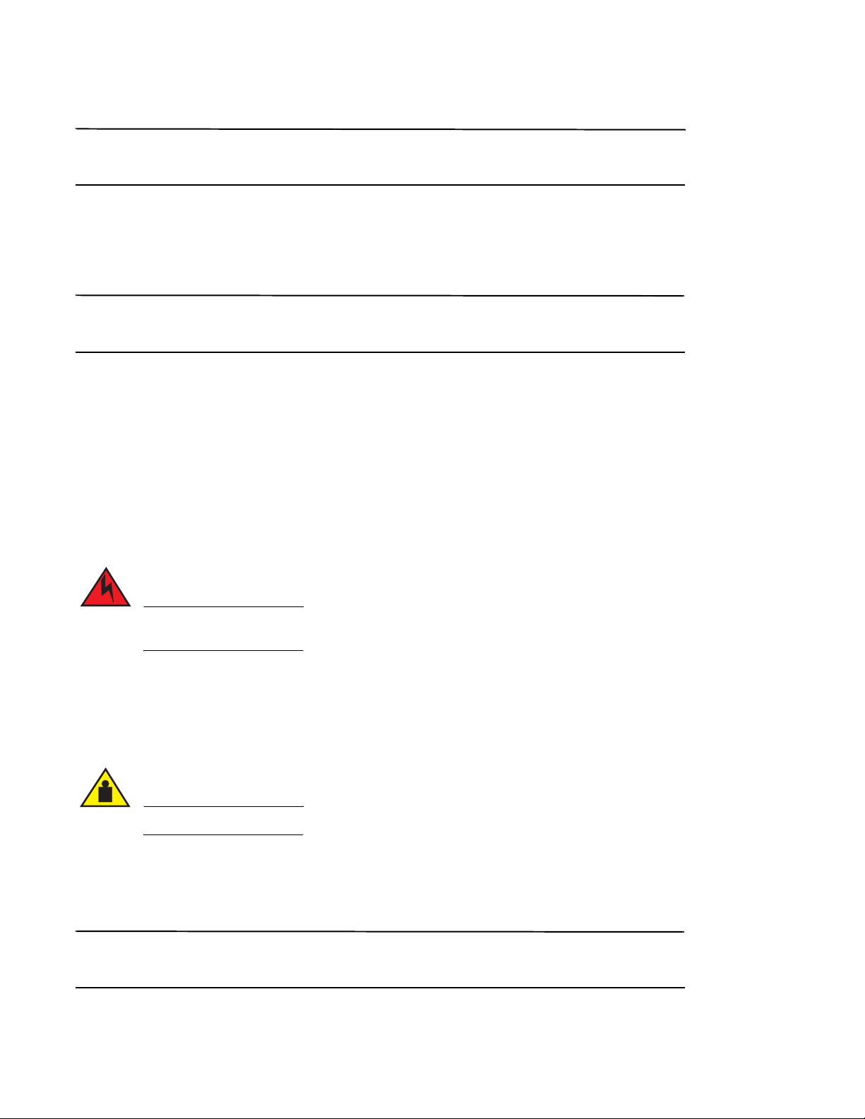
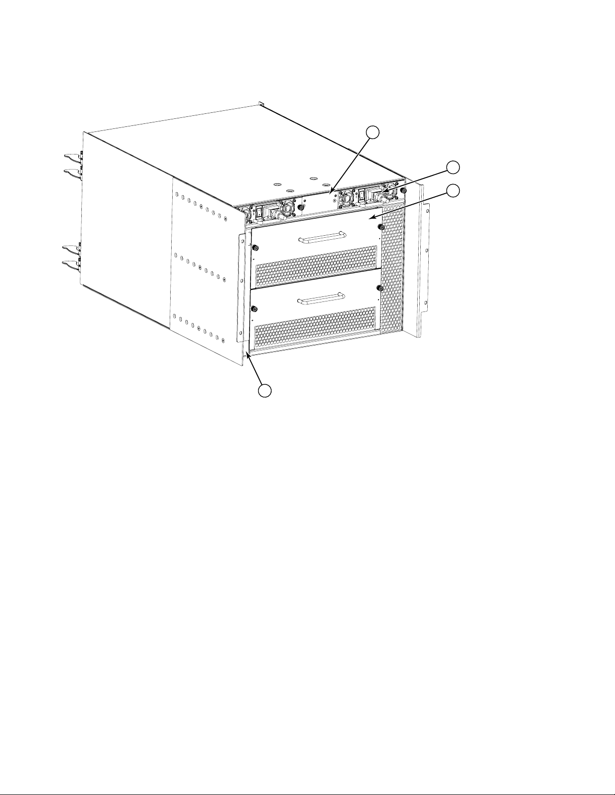
Brocade DCX 8510-4, port side
The following figures show a sample configuration of the port side of the Brocade DCX 8510-4.
Airflow for the Brocade DCX 8510-4 is from the nonport (non-cable) side to the left-hand side of the chassis as you
look from the port side. If you use the Port Side Exhaust Kit the air vents are on the port side of the chassis.
4 of 324 Brocade DCX 8510-4 Backbone QuickStart Guide
Publication Number: 53-1002367-01
Page 5
1 FC16-48 port blade (example, 4x) 3 Control processor blade (CP8) (2x)
1
4
2
3
2 Core switch blade (CR16-4) (2x) 4 Exhaust vent
FIGURE 1
Port side of the Brocade DCX 8510-4 (sample configuration)
Brocade DCX 8510-4 Backbone QuickStart Guide 5 of 324
Publication Number: 53-1002367-01
Page 6
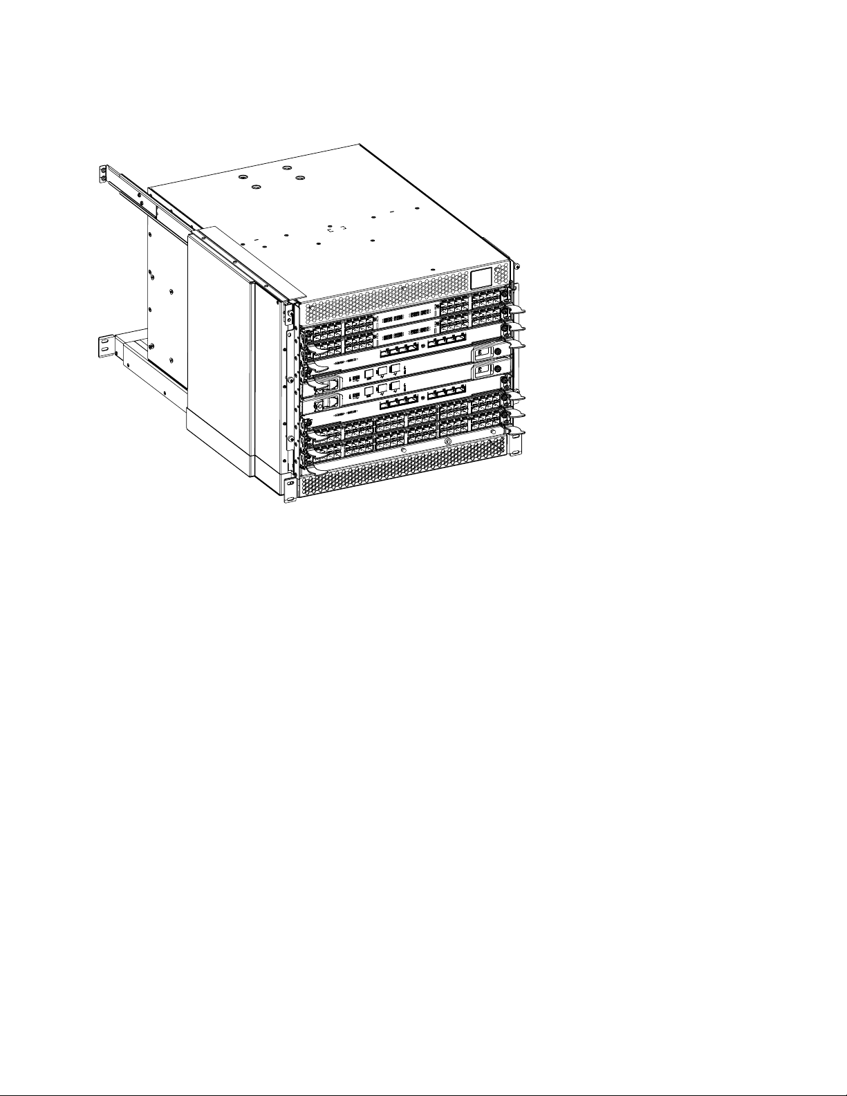
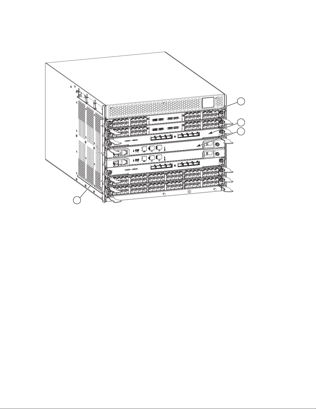
FIGURE 2
Port side of the Brocade DCX 8510-4 with the port side exhaust kit installed (sample configuration)
The following figure illustrates the change in the airflow pattern when the Port Side Exhaust Kit is installed.
6 of 324 Brocade DCX 8510-4 Backbone QuickStart Guide
Publication Number: 53-1002367-01
Page 7
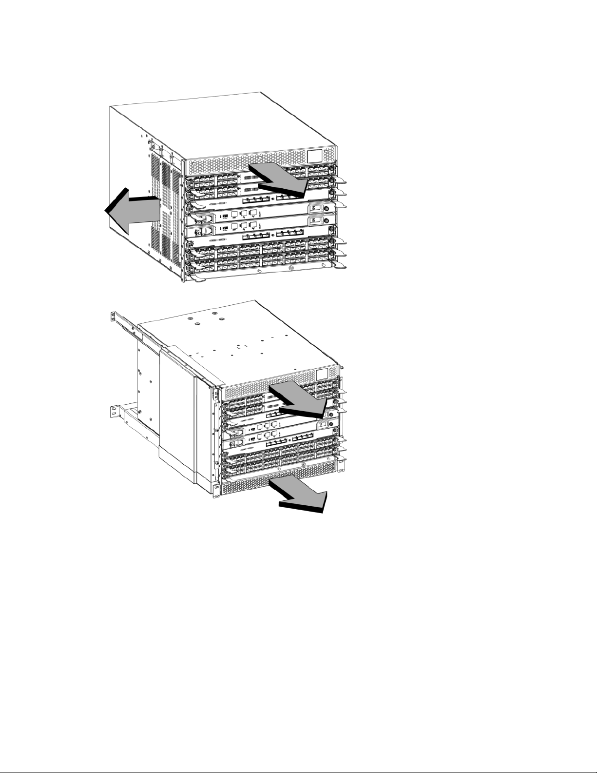
FIGURE 3
Airflow comparison of the Brocade DCX 8510-4 without (above)and with (below) the port side exhaust kit installed
(sample configuration)
Brocade DCX 8510-4, nonport side
The following figure shows a sample configuration of the nonport side view of the Brocade DCX 8510-4.
Brocade DCX 8510-4 Backbone QuickStart Guide 7 of 324
Publication Number: 53-1002367-01
Page 8
1 WWN card bezel (logo plate - WWN card behind) 2 Power supply (2x)
1
2
3
4
3 Blower assembly (2x) 4 Label with serial number and WWN
FIGURE 4
Time and items required for installation
You can set up and install the Brocade DCX 8510-4 in the following ways:
•
As a standalone unit on a flat surface.
•
In a 19-in. Electronic Industries Association (EIA) cabinet, using a Brocade DCX 8510-4, DCX-4S Rack Mount Kit
(either a 27-31 in. or 18-34 in. kit depending on rack used).
•
In a chassis with the Port Side Exhaust Kit (provided) in an approved rack.
•
In a mid-mount telecommunications (Telco) rack, using the Mid-Mount Rack Kit available from your Brocade DCX
8510-4 supplier.
This chapter describes how to set up the Brocade DCX 8510-4 as a standalone unit. For rack-mount installation
instructions, refer to the appropriate manual as described in the following table.
The following table describes the main installation and setup tasks, the estimated time required for each, and the
items required to complete the task based on a fully populated Brocade DCX 8510-4 (192 Fibre Channel ports using
the FC16-48 port blades). Configurations with fewer ports require less time. These time estimates assume a
prepared installation site and appropriate power and network connectivity.
Nonport side of the Brocade DCX 8510-4 (sample configuration)
8 of 324 Brocade DCX 8510-4 Backbone QuickStart Guide
Publication Number: 53-1002367-01
Page 9

NOTE
TABLE 1
Installation tasks, time, and items required
Installation task Time estimate Items required
Site preparation and unpacking Brocade
DCX 8510-4
Installing rack mount kit or
port side exhaust kit
Mounting and securing Brocade DCX
8510-4 in rack
Installing power cables and powering on
the Brocade DCX 8510-4
Establishing serial connection, logging on
to Brocade DCX 8510-4, and configuring IP
addresses
Installing an Ethernet cable, opening a
Telnet session, and configuring the
Brocade DCX 8510-4 domain ID, date and
time, and additional system parameters.
Verify and back up configuration.
Installing transceivers as needed 20 minutes (longer
Attaching fiber optic cables, cable ties, and
cable guides
30 minutes 1/2-in. socket wrench (to remove pallet bolts).
30 minutes Refer to the one or more of the following if you
30 minutes
20 minutes Power cables (provided in the Brocade DCX
20 minutes Serial cable (provided in the accessory kit).
20 minutes Ethernet cabling (optional) for Telnet access.
if using high-density
port blades)
2-3 hours Fiber optic cables, cable ties, and cable comb.
#2 Phillips screwdriver
(for cable management comb).
Pallet jack.
Hydraulic lift or assisted lift, able to raise to a
minimum of 140 cm (55 in.), with a minimum
capacity of 113 kg (250 lb). The Brocade DCX
8510-4 weighs 68 kg (150 lb) with four
FC16-48 port cards installed (192 ports).
are mounting the Brocade DCX 8510-4 in a
rack:
Brocade Port Side Exhaust Kit Installation
Procedure
Brocade DCX 8510-4, DCX-4S Mid-Mount Rack
Kit Installation Procedure or
Brocade DCX 8510-4, DCX-4S Rack Kit
Installation Procedure.
8510-4 accessory kit).
Workstation computer with a serial port or
terminal server port and a terminal emulator
application (such as HyperTerminal).
Ethernet IP addresses for the Brocade DCX
8510-4 chassis and for both control processor
blades: total three addresses.
Refer to the Fabric OS Administrator’s Guide.
SFP+, mSFP, and QSFP optical transceivers as
needed.
Site planning and safety guidelines
Read the safety notices before installation (“Safety notices”).
Read “Power specifications” in the Brocade DCX 8510-4 Hardware Reference Manual appendix to plan for meeting
power supply standards before installing the chassis.
Read “Managing cables” to plan for cable management.
The following steps are required to ensure correct installation and operation.
Brocade DCX 8510-4 Backbone QuickStart Guide 9 of 324
Publication Number: 53-1002367-01
Page 10

1. Provide a space that is 9 rack units (9U) high, 61.19 cm (24.09 in.) deep, and 43.74 cm (17.22 in.) wide. 1U is
NOTE
ATTENTION
equal to 4.45 cm (1.75 in.). If you do not use the provided port side exhaust kit, the space needs to be only 8
rack units (8U) high.
Plan to install the Brocade DCX 8510-4 with the nonport side facing the air-intake aisle. The Brocade DCX
8510-4 can be installed facing either direction, if serviceability and cooling requirements are met.
2. Ensure that dedicated electrical branch circuits with the following characteristics are available:
See “Power specifications” in the “Specifications” appendix for specific requirements depending on your
chassis configuration.
•
200 – 240 VAC, 50–60 Hz (two branch circuits) - recommended for high availability and maximum blade
usage
•
Two cables for 200 - 240 VAC service
•
Protected by a circuit breaker in accordance with local electrical codes
•
Supply circuit, line fusing, and wire size adequate to the electrical rating on the chassis nameplate
•
Location close to the chassis and easily accessible
•
Grounded outlets installed by a licensed electrician and compatible with the power cords
To maximize fault tolerance, connect each power cord to a separate power source.
3. Plan for cable management before installing the chassis.
Cables can be managed in a variety of ways, such as by routing cables below the chassis, to either side of the
chassis, through cable channels on the sides of the cabinet, or by using patch panels.
4. Ensure that the following is available for configuration of the Brocade DCX 8510-4:
•
Workstation with an installed terminal emulator, such as HyperTerminal
•
Serial cable (provided)
•
Three Ethernet cables (including one spare)
•
Access to an FTP server for backing up the switch configuration or collecting supportsave output data
(optional)
•
A Brocade USB stick for collecting supportsave output data (optional)
•
Transceivers (copper and optical) and compatible cables
5. Ensure that the air intake and exhaust vents have a minimum of two (2) inches of airspace.
6. Ensure that the air temperature on the air intake side is less than 40 degrees Celsius (104 degrees Fahrenheit)
during operation.
Items included with the Brocade DCX 8510-4
The Brocade DCX 8510-4 ships with the following:
10 of 324 Brocade DCX 8510-4 Backbone QuickStart Guide
Publication Number: 53-1002367-01
Page 11

•
NOTE
CAUTION
NOTE
Brocade DCX 8510-4 chassis, populated with:
-
Control processor blades (CP8)
-
Core switch blades (CR16-4)
-
Port blades, application blades, and encryption blades (included based on customer specification)
-
Blade slot filler panels (for slots not filled by blades)
-
Port side exhaust kit (included based on customer specification)
-
WWN cards
-
WWN bezel (logo plate)
-
Power supplies
-
Power supply filler panel (included if there is only one power supply)
-
Blower assemblies
-
Cable management finger assemblies
-
Chassis door
•
Accessory kit containing the following items:
-
Brocade DCX 8510-4 Backbone QuickStart Guide
-
Brocade Documentation CD (contains documents related to the Brocade DCX 8510-4)
-
ESD grounding strap
-
USB device
-
RS-232 serial cable. The RS-232 cable has an adapter at one end that can be removed to provide an
RJ-45-style connector.
•
Brocade DCX 8510-4, DCX-4S rack mount kit with instructions
Order the Brocade-branded optical transceivers (SFP+, mSFP, and QSFP). The Brocade DCX 8510-4 supports SWL,
LWL, and ELWL transceivers. The mSFPs and QSFPs are SWL transceivers only.
For information about the SFP+, mSFP, and QSFP transceivers that are qualified for the Brocade DCX 8510-4, go to
http://www.brocade.com/downloads/documents/matrices/Brocade_Compatibility_Matrix.pdf.
Unpacking and installing the Brocade DCX 8510-4
Use the following procedure to unpack and install your Brocade DCX 8510-4.
Use safe lifting practices when moving the product. (C015)
A fully populated Brocade DCX 8510-4 (four FC16-48 port cards, 192 ports) weighs approximately 68 kg (150 lbs) and
requires a hydraulic or assisted lift to install it.
Brocade DCX 8510-4 Backbone QuickStart Guide 11 of 324
Publication Number: 53-1002367-01
Page 12

1. Unpack the Brocade DCX 8510-4.
NOTE
DANGER
a. Cut the bands that encircle the packaging.
b. Remove the lid and the kits and foam from the top of the chassis.
c. Lift the cardboard box off the chassis and remove the plastic bag from around the chassis.
Save the packing materials for use when returning the old chassis.
d. Leave the chassis on top of the plastic shipping tray if the chassis must be transported to the installation
location.
The Brocade DCX 8510-4 packaging does not incorporate a wood pallet and pallet brackets. The chassis sits on
top of a plastic shipping tray.
2. Use a pallet jack or other assisted lift to transport the new chassis to the installation area. Doorways must be
wider than 36 in. (91 cm) to accommodate the chassis.
3. Remove the Brocade DCX 8510-4 port side exhaust kit (if ordered), accessory kit, packing foam, and antistatic
plastic from the chassis and set aside.
4. Remove the chassis door from the Brocade DCX 8510-4.
5. Remove the vertical cable management fingers.
6. Use a lift to raise the chassis to the correct level. If installing the chassis in a cabinet, follow the instructions
provided by the rack kit manufacturer.
7. If applicable, lock the wheels of the lift.
8. Gently slide the chassis onto the final installation surface, ensuring that it remains supported during the
transfer.
9. Ensure that the chassis is oriented so that the nonport side has access to intake air (cool).
10. Reinstall the vertical cable management fingers.
11. Reinstall the door. The door must be installed to meet EMI compliance.
Providing power to the Brocade DCX 8510-4
Complete the following steps to provide power to the chassis.
Use the supplied power cords. Ensure the facility power receptacle is the correct type, supplies the
required voltage, and is properly grounded. (D004)
1. Connect the two AC power cords to the two power supplies.
2. Connect the power cords to a power source with voltage of 200 to 240 VAC, 47 to 63 Hz or optionally to a power
source with voltage of 110 to 120 VAC, 47 to 63 Hz. If using any application blades in the chassis, the 200 to
240 VAC option is necessary in order to achieve power supply redundancy.
12 of 324 Brocade DCX 8510-4 Backbone QuickStart Guide
Publication Number: 53-1002367-01
Page 13

ATTENTION
Use of the high-voltage line (200 to 240 VAC) is highly recommended because of better power-conversion
ATTENTION
ATTENTION
NOTE
efficiency.
For a fully-loaded DCX 8510-4 or DCX-4S, 200 to 240 VAC is required for high availability (ability to hot swap a
failed power supply without affecting system operation.
3. Turn the AC power switches on the power supplies to I. The AC power switches light green when switched on and
power is supplied.
4. The Brocade DCX 8510-4 performs a power-on self-test (POST) each time it is powered on. POST takes
approximately 10 minutes and is complete when the indicator light activity displays the operational state.
You can bypass POST by using the fastBoot command. You can also disable POST for successive reboots on the
Brocade DCX 8510-4 using the diagDisablePost command.
Do not connect the switch to the network until the IP addresses are configured.
Managing cables
The vertical cable management fingers are attached to the rack to either side of the chassis door and allow for
simple cable management. The fingers can be installed without service disruption.
Route the cables along the front of the blades to keep LEDs visible. Leave at least one meter of slack for each fiber
optic cable to provide room to remove and replace blades.
The minimum radius to which a 50 micron cable should be bent under full tensile load is 2 in. For a cable under no
tensile load, that minimum is 1.2 in.
Cables can be organized and managed in a variety of ways, for example, using cable channels on the sides of the
cabinet or patch panels to minimize cable management. Following is a list of recommendations:
You should not use tie wraps with optical cables because they are easily overtightened and can damage the optic
fibers.
•
Plan for rack space required for cable management before installing the switch.
•
Leave at least 1 m (3.28 ft) of slack for each port cable. This provides room to remove and replace the
switch, allows for inadvertent movement of the rack, and helps prevent the cables from being bent to less
than the minimum bend radius.
•
If you are using Brocade ISL Trunking, consider grouping cables by trunking groups. The cables used in
trunking groups must meet specific requirements, as described in the Fabric OS Administrator’s Guide.
•
For easier maintenance, label the fiber optic cables and record the devices to which they are connected.
•
Keep LEDs visible by routing port cables and other cables away from the LEDs.
•
Use Velcro® type straps to secure and organize fiber optic cables.
Brocade DCX 8510-4 Backbone QuickStart Guide 13 of 324
Publication Number: 53-1002367-01
Page 14
ATTENTION
Do not route the cables in front of the air exhaust vent, which is located at the top of the port side of the chassis.If
2 3
4
1
you are using the Port Side Exhaust Kit with your Brocade DCX 8510-4, there is also an exhaust vent at the bottom of
the port side of the chassis. Use the vertical cable fingers to keep the cables away from this exhaust vent as well.
FIGURE 5
Vertical cable management finger assemblies
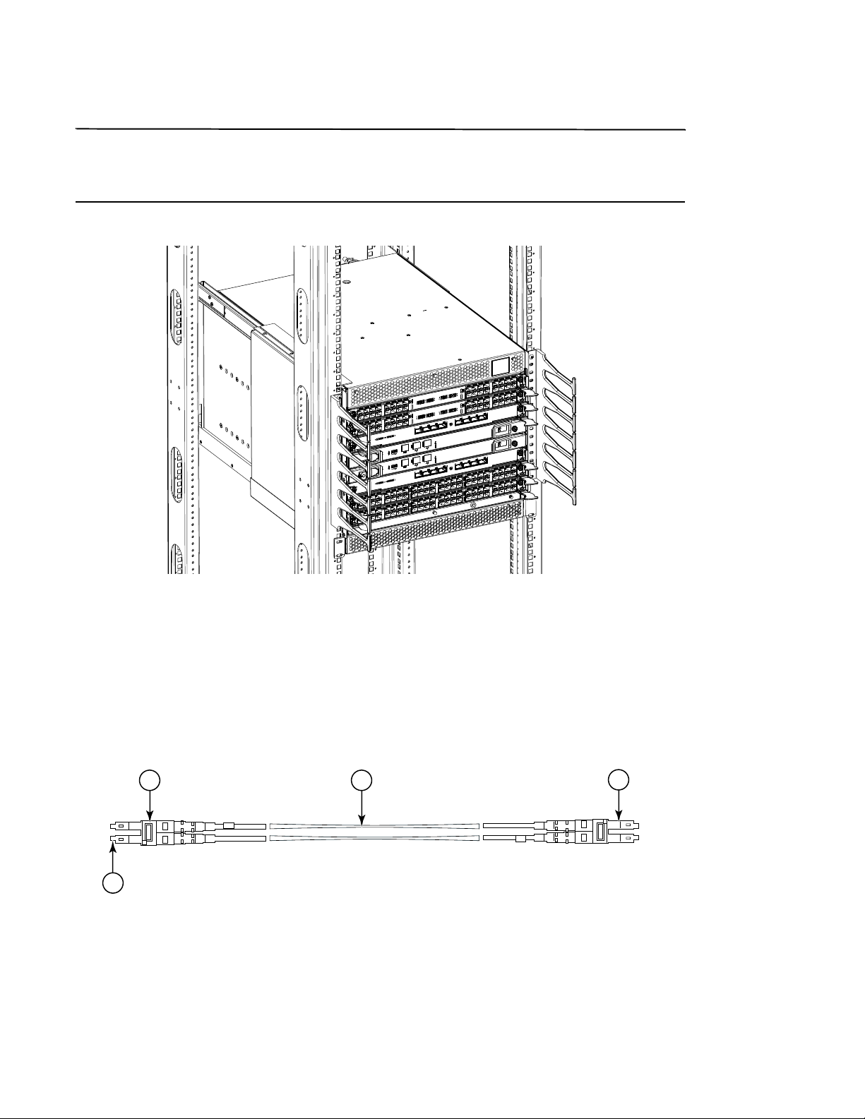
High density cabling
The FC8-64 high density port blade cannot use the standard LC cables because the pitch between optics in the new
mini-SFP (mSFP) transceiver is smaller than in standard SFPs. Patch cables and panels can be used to attach
standard size cabling to the blade if necessary. The figure below illustrates the mSFP to SFP patch cable. See “Best
Practices Guide: High Density Cable Management Solutions” (available at http://www.brocade.com) for cable
management guidelines for high-density port solutions, cable and patch panel part numbers.
1 mSFP connector 3 1.6 mm cable
2 Duplex clip (black) 4 SFP connector
FIGURE 6
Cable design for the mSFP patch cables for the FC8-64 high density port blade
14 of 324 Brocade DCX 8510-4 Backbone QuickStart Guide
Publication Number: 53-1002367-01
Page 15

Please note that the duplex clip on the mSFP end of the cable is black for easier recognition. See the appendix for a
NOTE
NOTE
ATTENTION
listing of the qualified mSFP optical cables for the FC8-64 port blade.
If ISL Trunking is in use, group the cables by trunking group. The ports are color-coded to indicate which ports can be
used in the same ISL Trunking group: eight ports marked with solid black ovals alternate with eight ports marked
with oval outlines. See the appendix for a listing of supported cable speeds and distances.
Installing QSFP cables (optional)
Use this procedure to remove and replace a QSFP cable.
The QSFP ports can be used only with an inter-chassis link (ICL) license. After the addition or removal of a license, the
license enforcement is performed on the ports only when the portdisable and portenable commands are issued on
the ports. An ICL license must be installed on all Brocade Backbones forming the ICL connection. Up to six neighboring
Brocade 8510 series chassis can be combined with the QSFP cables.
For the Brocade 8510 Backbones, an off-the-shelf QSFP cable up to 50 meters long can be used as an ICL cable.
For the 8510 series models, if the QSFP cables are not used, make sure the rubber gaskets are in the QSFP
transceivers.
The following table describes the connector port LED patterns and the recommended actions for those patterns.
TABLE 2
LED purpose Color Status Recommended action
QSFP
connector
status
QSFP connector port LEDs
No light (LED is off) No QSFP module, all four
QSFP ports are disabled
Steady amber QSFP module is in, all four
ports have no signal/no
sync.
Blinking amber Port is disabled or faulted,
FC link activity, segmented,
loopback mode, also
during transition between
QSFP cable insertion and
confirmation.
Steady green Both ends of QSFP cable
are in and all ports are
online. Full link is
established.
No action required if QSFP no
present or
verify that the QSFP is fully inserted.
No action required if QSFP only is
installed or
ensure that the cable is properly
connected. If the LED remains
amber, consult the Brocade DCX
8510-4 supplier.
Check for console messages or wait
for all four ports to come online.
No action required.
Follow this procedure to install the QSFP cables. Refer to the Fabric OS Administrator’s Guide for the configuration
procedure and requirements.
Brocade DCX 8510-4 Backbone QuickStart Guide 15 of 324
Publication Number: 53-1002367-01
Page 16
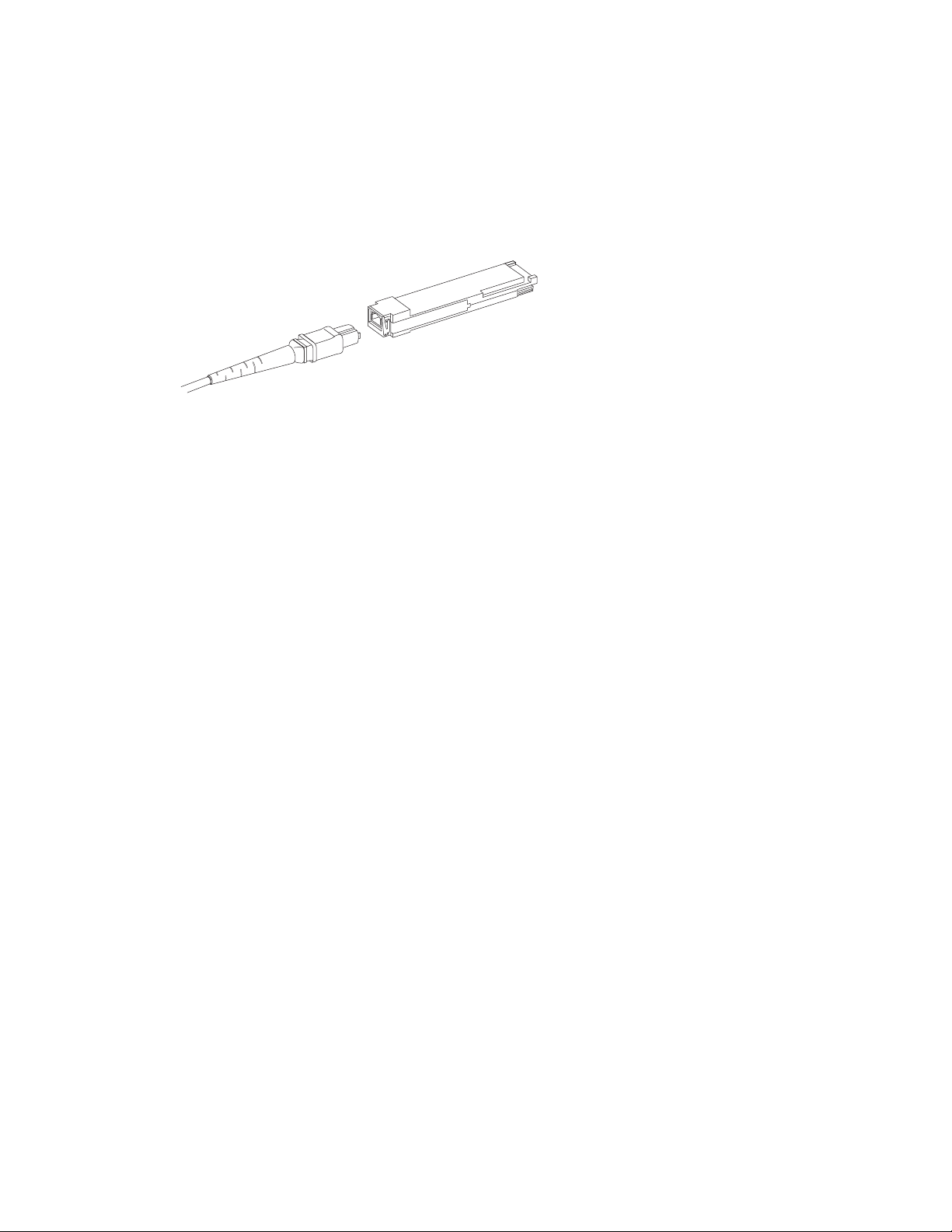
The figure below shows an QSFP cable and transceiver. The QSFP connectors on the core blades are labeled by
trunk group (trunking is optional) for ease of installation. The subsequent figures shows acceptable cabling
configurations for the ICL feature. The recommended topology is the parallel type where there are four QSFP cables
connected between any pair of Brocade 8510 series chassis.The full mesh configuration is also supported.
FIGURE 7
QSFP cable and transceiver
Installing a QSFP cable
Complete the following steps to replace a QSFP cable.
1. If the QSFP transceiver is being replaced, grasp the bail of the new QSFP and push the QSFP into the connector
on the blade until it is firmly seated. The QSFP is keyed to fit into the connector in one way. The status LED
initially blinks amber after installation, then displays steady amber.
2. Grasp the QSFP cable by the rubber housing and push it into the QSFP transceiver until it is firmly seated. The
cable housing is keyed to fit into the QSFP in one way.
The status LED displays steady amber until both ends of the cable are inserted and the link is established.
When the link is fully established, the LED displays steady green.
3. Repeat for each cable that requires replacement.
4. Once all the cables are attached, see the Fabric OS Administrator’s Guide for the configuration procedure.
Possible QSFP cable configurations
The following figure illustrates one possible QSFP cable configuration between two 8510 series chassis. Up to six
neighboring 8510 chassis can be connected as long as each of two cores in one chassis is interconnected with each
of two cores in the next chassis. This provides for inter-chassis link (ICL) trunking between chassis, ensuring
redundancy. Parallel connections between core blades are recommended, but both parallel and mesh cable
arrangements are supported.
16 of 324 Brocade DCX 8510-4 Backbone QuickStart Guide
Publication Number: 53-1002367-01
Page 17
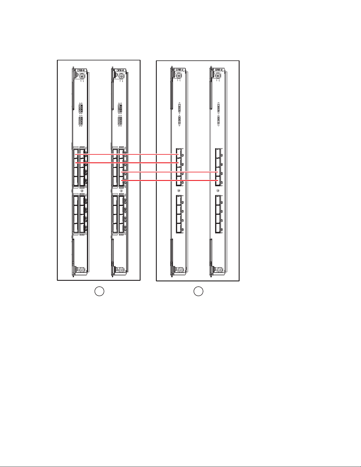
1 Chassis 1 2 Chassis 2
1 2
FIGURE 8
QSFP cable connections – 8510 sample configuration - parallel type
Six 8510 chassis can be connected in a core/edge configuration (two core/four edge) as shown in the figure below.
Although 8510-8 chassis are shown in the figure, the chassis can be either 8510-4 or 8510-8. The cabling scheme
should follow the parallel example shown in the previous figure.
Brocade DCX 8510-4 Backbone QuickStart Guide 17 of 324
Publication Number: 53-1002367-01
Page 18
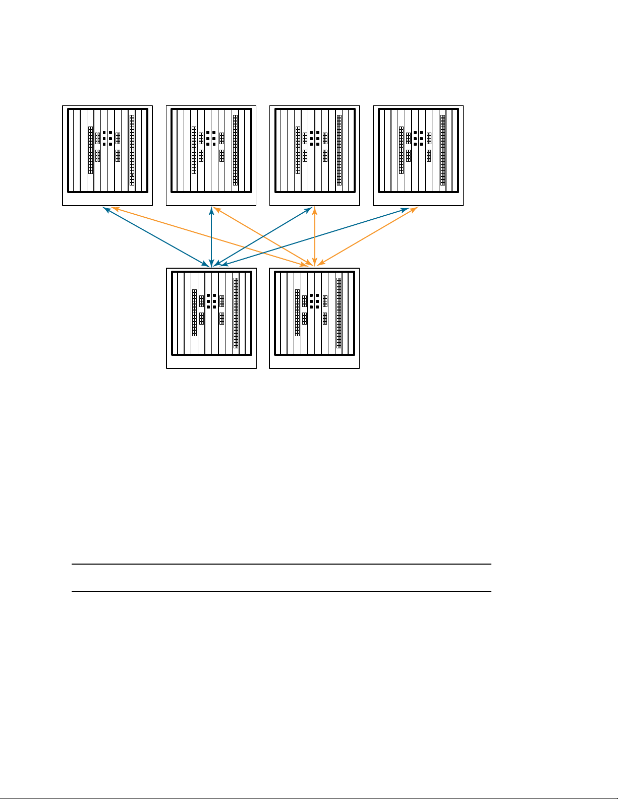
FIGURE 9
ATTENTION
DCX 8510 core/edge ICL topology
Establishing a serial connection and logging on to Brocade DCX 8510-4
To establish a serial connection to the console port on the Brocade DCX 8510-4, complete the following steps.
1. Verify that the Brocade DCX 8510-4 is powered on and that POST is complete by verifying that all power LED
indicators on the port, control processor, and core switch blades display a steady green light.
2. Remove the shipping cap from the CONSOLE port on the active CP. Use the serial cable provided with the
Brocade DCX 8510-4 to connect the CONSOLE port on the active CP to a computer workstation. The active CP
blade is indicated by an illuminated (blue) LED.
The CONSOLE port is intended primarily for the initial setting of the IP address and for service purposes.
3. Access the Brocade DCX 8510-4 using a terminal emulator application (such as HyperTerminal in a Windows
environment or tip in a UNIX environment).
4. Disable any serial communication programs running on the workstation (such as synchronization programs).
5. Open a terminal emulator application (such as HyperTerminal on a PC, or term, tip, or kermit in a UNIX
environment), and configure the application as follows:
18 of 324 Brocade DCX 8510-4 Backbone QuickStart Guide
Publication Number: 53-1002367-01
Page 19

•
NOTE
In a Windows environment:
Parameter Value
Bits per second 9600
Data bits 8
Parity None
Stop bits 1
Flow control None
•
In a UNIX environment, enter the following string at the prompt:
tip /dev/ttyb -9600
If ttyb is already in use, use ttya instead and enter the following string at the prompt:
tip /dev/ttya -9600
When the terminal emulator application stops reporting information, press Enter. You receive the following login
prompt:
CP0 Console Login:
6. Proceed to the next task.
Logging on to the Brocade DCX 8510-4
To log in to the Brocade DCX 8510-4 through the serial connection, follow these steps.
1. Log in to the Brocade DCX 8510-4 as admin. The default password is password. At the initial login, you are
prompted to enter new admin and user passwords. Make sure to write down the new passwords and keep this
information in a secure location.
Fabric OS (swDir)
swDir login: admin
Password:
Please change your passwords now.
Use Control-C to exit or press 'Enter' key to proceed.
swDir:admin>
2. (Optional) Modify passwords. To skip modifying the password, press Ctrl-C. For more information on passwords,
refer to the Fabric OS Administrator’s Guide.
Passwords can be 8 to 40 characters long. They must begin with an alphabetic character. They can include
numeric characters, the dot (.), and the underscore (_) only. Passwords are case-sensitive, and they are not
displayed when you enter them on the command line.
For more information on passwords, refer to the Fabric OS Administrator’s Guide.
Brocade DCX 8510-4 Backbone QuickStart Guide 19 of 324
Publication Number: 53-1002367-01
Page 20

Configuring IP addresses
NOTE
ATTENTION
NOTE
The Brocade DCX 8510-4 requires three IP addresses, which are configured using the ipAddrSet command. IP
addresses are required for both CP blades (CP0 and CP1) and for the chassis management IP (shown as SWITCH
under the ipAddrShow command) in the Brocade DCX 8510-4.
The default IP addresses and host names for the Brocade DCX 8510-4 are:
– 10.77.77.75 / CP0 (the CP blade in slot 4 at the time of configuration)
– 10.77.77.74 / CP1 (the CP blade in slot 5 at the time of configuration)
Resetting an IP address while the Brocade DCX 8510-4 has active IP traffic or has management and monitoring tools
running, such as DCFM, Fabric Watch, and SNMP, can cause traffic to be interrupted or stopped.
Complete the following steps to set the IP addresses for the Brocade DCX 8510-4.
1. Log in to the active CP as admin using the serial cable connection.
2. Set up the Brocade DCX 8510-4 IP address by entering the ipaddrset -chassis command:
swDir:admin> ipAddrSet -chassis
Enter the information at the prompts. Specify the -chassis IP address. The -sw 0 IP address is not valid on this
chassis.
The addresses 10.0.0.0 through 10.0.0.255 are reserved and used internally by the Brocade DCX 8510-4.
External IPs must not use these addresses.
3. Set up the CP0 IP address by entering the ipaddrset -cp 0 command:
swDir:admin> ipAddrSet -cp 0
Enter the information at the prompts.
4. Set up the CP1 IP address by entering the ipaddrset -cp 1 command:
swDir:admin> ipAddrSet -cp 1
Enter the information at the prompts.
This is a sample IP configuration:
swDir:admin> ipaddrset -chassis
Ethernet IP Address [0.0.0.0]: 192.168.1.1
Ethernet Subnetmask [0.0.0.0]: 255.255.255.0
Fibre Channel IP Address [0.0.0.0]:
Fibre Channel Subnetmask [0.0.0.0]:
Issuing gratuitous ARP...Done.
Committing configuration...Done.
swDir:admin> ipaddrset -cp 0
Host Name [cp0]:
Ethernet IP Address [10.77.77.75]: 192.168.1.2
Ethernet Subnetmask [0.0.0.0]: 255.255.255.0
Gateway IP Address [0.0.0.0]: 192.168.1.254
IP address is being changed...Done.
Committing configuration...Done.
20 of 324 Brocade DCX 8510-4 Backbone QuickStart Guide
Publication Number: 53-1002367-01
Page 21

swDir:admin> ipaddrset -cp 1
NOTE
NOTE
Host Name [cp1]:
Ethernet IP Address [10.77.77.74]: 192.168.1.3
Ethernet Subnetmask [0.0.0.0]: 255.255.255.0
Gateway IP Address [0.0.0.0]: 192.168.1.254
IP address of remote CP is being changed...Done.
Committing configuration...Done.
Establishing an Ethernet connection
Connecting the CP blades to a private network/VLAN is recommended.
After using a serial connection to configure the IP addresses for the Brocade DCX 8510-4, you can connect the
active CP blade to the local area network (LAN).
By establishing an Ethernet connection, you can complete the Brocade DCX 8510-4 configuration using either a
serial session, Telnet, or management applications, such as Web Tools or Brocade Network Advisor.
Perform the following steps to establish an Ethernet connection to the Brocade DCX 8510-4.
1. Remove the shipping plug from the Ethernet port on the active CP blade.
2. Insert one end of an Ethernet cable into the Ethernet port.
3. Connect the other end to an Ethernet 10/100/1000 BaseT LAN.
The Brocade DCX 8510-4 can be accessed through a remote connection using the command line via Telnet or
any of the management tools, such as Web Tools or Brocade Network Advisor.
4. To complete any additional Brocade DCX 8510-4 configuration procedures through a Telnet session, log in to the
Brocade DCX 8510-4 by Telnet, using the admin login. The default password is password.
Customizing a switch name
The switch name of the Brocade DCX 8510-4 can be up to 30 characters long using Fabric OS release 6.3.0 or later;
can include letters, numbers, hyphens, and underscore characters; and must begin with a letter.
Changing the name causes a domain address format RSCN to be issued.
1. Type switchName followed by the new name in double quotes.
swDir:admin> switchName "swModularSwitch5"
Committing configuration...
Done.
swModularSwitch5:admin>
2. Record the new name for reference.
Brocade DCX 8510-4 Backbone QuickStart Guide 21 of 324
Publication Number: 53-1002367-01
Page 22

Customizing a chassis name
The chassis name of the Brocade DCX 8510-4 can be up to 15 characters long; can include letters, numbers,
hyphens, and underscore characters; and must begin with a letter.
1. Enter chassisName followed by the new name in double quotes.
switch:admin> chassisname "DCX8510_chassis"
Committing configuration...
Done.
2. Enter chassisName by itself to show the name.
switch:admin> chassisname
DCX8510_chassis
3. Record the new name for reference.
Setting the Domain ID
Each switch in the fabric must have a unique domain ID. The domain ID can be manually set through the configure
command or can be automatically set. The default domain ID for the Brocade DCX 8510-4 is 1. Use the fabricShow
command to view the already assigned domain IDs.
1. Enter switchDisable to disable the Brocade DCX 8510-4.
2. Enter configure.
3. Enter y at the Fabric parameters prompt:
Fabric parameters (yes, y, no, n): [no] y
4. Enter a unique domain ID:
Domain: (1.239) [1] 3
5. Complete the remaining prompts or press Ctrl+D to accept the settings and exit.
6. Enter switchEnable to reenable the Brocade DCX 8510-4.
Verifying the persistent PID feature
Before connecting the Brocade DCX 8510-4 to the fabric, verify that the WWN Based persistent port identifier (PID)
feature on the Brocade DCX 8510-4 matches the other switches in the fabric. This parameter must be identical for
all switches in the fabric and is set using the configure command as shown below:
switch:admin>configure
Configure...
Fabric parameters (yes, y, no, n): [no] y
Domain: (1..239) [1]
Enable a 256 Area Limit
(0 = No,
1 = Zero Based Area Assignment,
2 = Port Based Area Assignment): (0..2) [0] 1
WWN Based persistent PID (yes, y, no, n): [no] yes
22 of 324 Brocade DCX 8510-4 Backbone QuickStart Guide
Publication Number: 53-1002367-01
Page 23

<command output truncated>
NOTE
You can check the PID setting using the configshow command as in the following example. You can use the | grep -i
pid qualifier to pinpoint the PID information.
switch:admin> configshow | grep -i pid
fabric.ops.mode.pidFormat:1
fabric.wwnPidMode:1
The 1 indicates that the WWN Based persistent PID feature is enabled. The default value is 0 for disabled.
Installing transceivers
The first procedure is used to install SFP+s and mSFPs (FC8-64 port card only) and cables to the Brocade DCX
8510-4. The second procedure is used to install the QSFP transceivers in the 16 Gbps core blades.
Installing SFP-type transceivers
Complete the following steps to install SFP-type optical transceivers.
mSFP transceivers are compatible only with the FC8-64 port blade. While they will fit in other blades, this
configuration is unsupported and will generate an error.
The ports are color-coded to indicate which can be used in the same port group for trunking (trunking port groups
can be up to eight ports). The ports and cables used in trunking groups must meet specific requirements. Refer to
the Fabric OS Administrator’s Guide for more information.
1. Add the optical transceivers and cables to the Fibre Channel ports.
The ports are color-coded to indicate which can be used in the same port group for trunking (trunking port
groups can be up to 8 ports). The ports and cables used in trunking groups must meet specific requirements.
Refer to the Fabric OS Administrator’s Guide.
2. Position one of the optical transceivers so that the key is oriented correctly to the port. Insert the transceiver into
the port until it is firmly seated and the latching mechanism clicks.
Transceivers are keyed so that they can only be inserted with the correct orientation. If a transceiver does not
slide in easily, ensure that it is correctly oriented.
3. Position a cable so that the key (the ridge on one side of the cable connector) is aligned with the slot in the
transceiver. Insert the cable into the transceiver until the latching mechanism clicks.
Cables are keyed so that they can be inserted in only one way. If a cable does not slide in easily, ensure that it is
correctly oriented.
4. Repeat steps 1 through 3 for the remaining ports.
5. Organize the cables See “Managing Cables.”
6. Verify the Brocade DCX 8510-4 and port status using the switchShow command.
7. Verify fabric connectivity using the fabricShow command.
Brocade DCX 8510-4 Backbone QuickStart Guide 23 of 324
Publication Number: 53-1002367-01
Page 24

Installing QSFP transceivers
Follow these steps to install the QSFPs and cables in the 16 Gbps core blades. These transceivers and cables are
used to form the inter-chassis links (ICL) with neighboring DCX 8510 Backbones.
The transceivers should be installed in the blades before connecting the cables.
Because each QSFP contains four 16 Gbps ports, be aware that any problems with one port could affect all four
ports in the quad if the QSFP has to be replaced.
1. Position one of the QSFP transceivers so that the key is oriented correctly to the port. Insert the transceiver into
the port until it is firmly seated.
Transceivers are keyed so that they can only be inserted with the correct orientation. If a transceiver does not
slide in easily, ensure that it is correctly oriented.
When the transceiver is correctly seated, the status LED will flash amber several times and then turn solid
amber.
2. Remove the protective cap from the special QSFP cable and insert it into the transceiver until it is firmly seated.
The cables are also keyed to fit into the transceivers correctly.
When the cable is correctly seated, the status LED will change from amber to green.
Repeat steps 1 and 2 for the remaining ICL
3. Organize the cables See “Managing Cables.”
4. Verify the Brocade DCX 8510-4 and connector and port status using the switchShow -qsfp command.
A sample of the command output is shown below. The example is from a DCX 8510-4 with a core blade installed
in slot 3. Some details for the 8510-8 will be different, but the reported information for the QSFPs will be similar.
Note that the State reported for an unconnected QSFP (shown QSFP 0 and Ports 0-3 below) is No_SigDet. This is
different from the State of No_Synch that is reported for regular SFPs that are unconnected.
QSFP 7 (ports 3/28-3/31, Index 748-751) in the following example shows the results for a connected QSFP.
switch:FID128:admin> switchshow -qsfp
switchName: switch name
switchType: 121.3
switchState: Online
switchMode: Native
switchRole: Subordinate
switchDomain: 75
switchId: fffc4b
switchWwn: 10:00:00:05:1e:4f:eb:00
zoning: ON (zoning name)
switchBeacon: OFF
FC Router: OFF
Allow XISL Use: OFF
LS Attributes: [FID: 128, Base Switch: No, Default Switch: Yes, Address Mode 0]
Index Slot Port QSFP Address Media Speed State Proto
=============================================================
256 3 0 0 ------ id 16G No_SigDet FC
257 3 1 0 ------ id 16G No_SigDet FC
258 3 2 0 ------ id 16G No_SigDet FC
259 3 3 0 ------ id 16G No_SigDet FC
260 3 4 1 ------ -- 16G No_Module FC
261 3 5 1 ------ -- 16G No_Module FC
262 3 6 1 ------ -- 16G No_Module FC
24 of 324 Brocade DCX 8510-4 Backbone QuickStart Guide
Publication Number: 53-1002367-01
Page 25

263 3 7 1 ------ -- 16G No_Module FC
264 3 8 2 ------ -- 16G No_Module FC
265 3 9 2 ------ -- 16G No_Module FC
266 3 10 2 ------ -- 16G No_Module FC
267 3 11 2 ------ -- 16G No_Module FC
268 3 12 3 ------ -- 16G No_Module FC
269 3 13 3 ------ -- 16G No_Module FC
270 3 14 3 ------ -- 16G No_Module FC
271 3 15 3 ------ -- 16G No_Module FC
736 3 16 4 ------ -- 16G No_Module FC
737 3 17 4 ------ -- 16G No_Module FC
738 3 18 4 ------ -- 16G No_Module FC
739 3 19 4 ------ -- 16G No_Module FC
740 3 20 5 ------ -- 16G No_Module FC
741 3 21 5 ------ -- 16G No_Module FC
742 3 22 5 ------ -- 16G No_Module FC
743 3 23 5 ------ -- 16G No_Module FC
744 3 24 6 ------ -- 16G No_Module FC
745 3 25 6 ------ -- 16G No_Module FC
746 3 26 6 ------ -- 16G No_Module FC
747 3 27 6 ------ -- 16G No_Module FC
748 3 28 7 ------ id 16G Online FC E-Port 10:00:00:05:1e:39:e4:5a
trunkmaster name (Trunk master)
749 3 29 7 ------ id 16G Online FC E-Port 10:00:00:05:1e:39:e4:5a
trunkmaster name
750 3 30 7 ------ id 16G Online FC E-Port 10:00:00:05:1e:39:e4:5a
trunkmaster name (Trunk master)
751 3 31 7 ------ id 16G Online FC E-Port 10:00:00:05:1e:39:e4:5a
trunkmaster name (Trunk master)
(Trunk master)
Confirming software licenses
Depending on the vendor agreement, certain licenses are factory installed on the Brocade DCX 8510-4. To
determine which licenses are enabled, use the licenseShow command.
swDir:admin> licenseshow
AAbbccDDeeFFeeGG:
Web license
Zoning license
Extended Fabric license
Fabric Watch license
Performance Monitor license
Trunking license
Security license
In this example, the license key is AAbbccDDeeFFeeGG. Keep a copy of the license key for reference.
The 64-bit chassis License ID is required to obtain and activate licenses for the Brocade DCX 8510-4. The chassis
License ID is available through the licenseIdShow command. The licenseShow and licenseIdShow commands must
be typed through the active CP blade. Refer to the Fabric OS Administrator’s Guide for information about unlocking
and maintaining licenses.
Brocade DCX 8510-4 Backbone QuickStart Guide 25 of 324
Publication Number: 53-1002367-01
Page 26

Backing up the configuration
NOTE
NOTE
Complete the following steps to back up the configuration for the Brocade DCX 8510-4.
1. Check the LEDs to verify that all components are functional.
2. If necessary, log on to the switch by Telnet, using the admin account.
3. Verify the correct operation of the Brocade DCX 8510-4 by entering the switchShow command from the
workstation. This command provides information about switch and port status.
4. Verify the correct operation of the Brocade DCX 8510-4 in the fabric by entering the fabricShow command from
the workstation. This command provides general information about the fabric.
5. To back up the configuration, run the following two steps:
a. Enter the configupload -vf command. This command uploads the Brocade DCX 8510-4 virtual fabric data.
b. Enter the configupload command. This command uploads the Brocade DCX 8510-4 configuration.
6. You can run the following commands to see additional configuration information that you can copy to a file to
save:
•
configShow
•
ipaddrShow
•
licenseShow
•
switchShow
Alternatively, you can save the configuration file to a Brocade USB device by using the usbstorage command.
Passwords are not saved in the configuration file, and are not uploaded during a configuration upload.
It is recommended that the configuration be backed up on a regular basis to ensure that a complete configuration is
available for downloading to a replacement Brocade DCX 8510-4.
26 of 324 Brocade DCX 8510-4 Backbone QuickStart Guide
Publication Number: 53-1002367-01
Page 27

53-1002367-01
2011 年 8 月 8 日
Brocade DCX 8510-4
主干
®
快速启动指南
53-1002367-01
*53-1002367-01*
Page 28
版权所有 © 2011, Brocade Communications Systems, Incorporated。
Brocade、B-wing 符号、BigIron、DCFM、DCX、Fabric OS、FastIron、IronView、NetIron、SAN Health、ServerIron、Tur boIr on 和 Wingspan 是
Brocade Communications Systems, Inc., 在美国和 / 或其他国家或地区的注册商标, Brocade Assurance、Brocade NET Health、Brocade One、
Extraordinary Networks、MyBrocade、 VCS 和 VDX 是 Brocade Communications Systems, Inc. 在美国和 / 或其他国家或地区的商标。本文中使
用的其他品牌、产品或服务名称是其各自所有者的商标或服务商标。
注意:本文档仅为提供信息,不对任何有关 Brocade 已提供或将要提供的设备、设备功能或服务提出明示或暗示的担保。 Brocade 保留对此
文档进行更改的权利,无需预先通知且不对其使用承担任何责任。本参考文档中描述的功能可能目前并不可用。联系 Brocade 销售办公室,
以了解有关功能和产品可用性的相关信息。出口本文档中所含技术数据可能需要美国政府的出口许可。
本文档作者及 Brocade Communications Systems, Inc. 不对任何个人或实体因本出版物或其随附的计算机程序中所含信息而产生的损失、费
用、责任或损害承担任何义务或责任。
本文档中所描述产品可能含有受 GNU 一般公共许可或其他开放源代码许可协议保护的 “ 开放源代码 ” 软件。要了解 Brocade 产品中包含
了哪些开放源代码软件、查阅适用于此开放源代码软件的许可条款、以及获取该编程源代码的备份,请访问
http://www.brocade.com/support/oscd。
Brocade Communications Systems, Incorporated
公司及拉美总部
Brocade Communications Systems, Inc.
130 Holger Way
San Jose, CA 95134
Tel :1-408-333-8000
Tel :1-408-333-8101
E-mail:info@brocade.com
欧洲总部
Brocade Communications Switzerland Sàrl
Centre Swissair
Tour B - 4ème étage
29, Route de l'Aéroport
Case Postale 105
CH-1215 Genève 15
Switzerland
Tel : +41 22 799 5640
Tel : +41 22 799 5641
E-mail:info@brocade.com
亚太总部
Brocade Communications Systems China HK, Ltd.
北京
朝阳区
光华路 1 号
2718 和 2818 室 (100020)
电话:+8610 6588 8888
传真:+8610 6588 9999
E-mail:info@brocade.com
亚太总部
Brocade Communications Systems Co., Ltd. (Shenzhen WFOE)
中国
天河北路
233 号 中信广场
1308 室
电话:+8620 3891 2000
传真:+8620 3891 2111
E-mail:info@brocade.com
文档历史版本
文档标题 出版编号 更改摘要 出版日期
Brocade DCX 8510-4 主干快速启动指南
Brocade DCX 8510-4 主干快速启动指南
53-1002178-01
53-1002178-02
新文档。 2011 年 4 月
几处小的更改,包括新图
2011 年 8 月
片、一般性文本、新的联机
链接、 IP 地址和 PID 声明。
28/324 Brocade DCX 8510-4
出版编号:
主干快速启动指南
53-1002367-01
Page 29

本指南目录
注意
•
简介. . . . . . . . . . . . . . . . . . . . . . . . . . . . . . . . . . . . . . . . . . . . . . . . . . . . . . . . . . 29
•
安全注意事项. . . . . . . . . . . . . . . . . . . . . . . . . . . . . . . . . . . . . . . . . . . . . . . . . . 30
•
Brocade DCX 8510-4,端口侧 . . . . . . . . . . . . . . . . . . . . . . . . . . . . . . . . . . . . 30
•
Brocade DCX 8510-4,非端口侧 . . . . . . . . . . . . . . . . . . . . . . . . . . . . . . . . . . 34
•
安装所需的时间和物品. . . . . . . . . . . . . . . . . . . . . . . . . . . . . . . . . . . . . . . . . . 34
•
场地规划与安全守则. . . . . . . . . . . . . . . . . . . . . . . . . . . . . . . . . . . . . . . . . . . . 35
•
Brocade DCX 8510-4 的标配. . . . . . . . . . . . . . . . . . . . . . . . . . . . . . . . . . . . . . 37
•
拆封并安装 Brocade DCX 8510-4. . . . . . . . . . . . . . . . . . . . . . . . . . . . . . . . . . 37
•
为 Brocade DCX 8510-4 供电 . . . . . . . . . . . . . . . . . . . . . . . . . . . . . . . . . . . . . 38
•
管理电缆. . . . . . . . . . . . . . . . . . . . . . . . . . . . . . . . . . . . . . . . . . . . . . . . . . . . . . 39
•
安装 QSFP 电缆 (可选) . . . . . . . . . . . . . . . . . . . . . . . . . . . . . . . . . . . . . . . . 41
•
建立串行连接并登录 Brocade DCX 8510-4. . . . . . . . . . . . . . . . . . . . . . . . . . 44
•
配置 IP 地址 . . . . . . . . . . . . . . . . . . . . . . . . . . . . . . . . . . . . . . . . . . . . . . . . . . . 46
•
建立以太网连接. . . . . . . . . . . . . . . . . . . . . . . . . . . . . . . . . . . . . . . . . . . . . . . . 47
•
自定义交换机名称. . . . . . . . . . . . . . . . . . . . . . . . . . . . . . . . . . . . . . . . . . . . . . 47
•
自定义机箱名称. . . . . . . . . . . . . . . . . . . . . . . . . . . . . . . . . . . . . . . . . . . . . . . . 48
•
设置域 ID . . . . . . . . . . . . . . . . . . . . . . . . . . . . . . . . . . . . . . . . . . . . . . . . . . . . . 48
•
确认永久 PID 功能 . . . . . . . . . . . . . . . . . . . . . . . . . . . . . . . . . . . . . . . . . . . . . . 48
•
确认软件许可证. . . . . . . . . . . . . . . . . . . . . . . . . . . . . . . . . . . . . . . . . . . . . . . . 51
•
备份配置. . . . . . . . . . . . . . . . . . . . . . . . . . . . . . . . . . . . . . . . . . . . . . . . . . . . . . 52
简介
本指南提供有关快速拆封、安装 Brocade DCX 8510-4 并将其设置为独立设备的说明。请注意以下附加说明文
件:
•
有关详细安装和配置说明,请参阅 《Brocade DCX 8510-4 主干硬件参考手册》。
•
有关特定于机架的安装说明,请参阅相应的机架安装或中置安装步骤。
Brocade DCX 8510-4 可以通过以下方式进行安装:
•
立于平整表面上的独立设备。
•
安装在 Brocade 合格机架中带有端口侧排气工具包 (附带)的机箱中。
•
安装在 19 英寸 电子工业协会 (EIA) 机柜中,使用 Brocade 8510-4、DCX-4S 机架安装工具包(27-31 英寸或
18-34 英寸 工具包,视使用的机架而定)。
•
在中置安装电信 (Telco) 机架中,使用 Brocade DCX 8510-4 供应商提供的 Brocade 8510-4、 DCX-4S 中置机
架工具包 (可选)。
本指南中列出设置 Brocade DCX 8510-4 主干所需的基本配置步骤。其他配置信息在 《Brocade DCX 8510-4 主干
硬件参考手册》和 《Fabric OS 管理员指南》中提供。
要符合 EMI 认证,必须安装 Brocade DCX 8510-4 的门。如果没有使用 QSFP 电缆,还建议在核心刀片 QSFP 插座
中安装端口橡皮塞。
Brocade DCX 8510-4
出版编号:
53-1002367-01
主干快速启动指南
29/324
Page 30
安全注意事项
注
危险
小心
注
使用本产品时,请遵守本手册中的危险、小心和注意等注意事项。注意事项伴有表示安全条件严重性的符号。
翻译的安全注意事项位于 《Brocade 产品安全注意事项》出版物中,该出版物在本产品附带的 CD-ROM 中。
危险和小心注意事项基于其 ID 按数字顺序列出,在每个注意事项的末尾显示,例如 (D004)。使用此 ID 可查找
《Brocade 产品安全注意事项》中以下危险和小心注意事项的翻译。
危险注意事项
危险注意事项用于引起对可能致命或极其危险的情况的关注。危险注意事项伴有一个闪电符号,表示危险
电气情况。安装或维修本设备之前,请阅读并遵从以下危险注意事项。
使用提供的电源线。确保设施电源插座为正确的类型、提供所需的电压并且已正确接地。 (D004)
小心注意事项
小心注意事项引起对于某些现有情况的注意,这些情况可能导致对人的危险。安装或维修本设备之前,请
阅读并遵从以下小心注意事项。
移动本产品时,请遵照安全提起做法。 (C015)
Brocade DCX 8510-4,端口侧
下图显示 Brocade DCX 8510-4 端口侧的示例配置。
Brocade DCX 8510-4 的气流从机箱的非端口 (非电缆)侧到左侧,正如从端口侧看到的一样。如果使用端口侧
排气工具包,则通风口位于机箱的端口侧。
30/324 Brocade DCX 8510-4
出版编号:
主干快速启动指南
53-1002367-01
Page 31

1 FC16-48 端口刀片 (示例, 4x) 3 控制处理器刀片 (CP8) (2x)
1
4
2
3
2 核心交换机刀片 (CR16-4) (2x) 4 排气口
1
Brocade DCX 8510-4 的端口侧 (示例配置)
图
Brocade DCX 8510-4
出版编号:
53-1002367-01
主干快速启动指南
31/324
Page 32

装有端口侧排气工具包的 Brocade DCX 8510-4 的端口侧 (示例配置)
2
图
下图说明装有端口侧排气工具包时气流模式的更改。
32/324 Brocade DCX 8510-4
出版编号:
主干快速启动指南
53-1002367-01
Page 33

未安装 (上)和安装 (下)端口侧排气工具包的 Brocade DCX 8510-4 的气流比较 (示例配置)
3
图
Brocade DCX 8510-4
出版编号:
53-1002367-01
主干快速启动指南
33/324
Page 34

Brocade DCX 8510-4,非端口侧
1
2
3
4
下图显示 Brocade DCX 8510-4 非端口侧视图的示例配置。
1 WWN 卡挡板 (徽标板 - 背后为 WWN 卡) 2 电源设备 (2x)
3 鼓风机部件 (2x) 4 带有序列号和 WWN 的标签
Brocade DCX 8510-4 的非端口侧 (示例配置)
4
图
安装所需的时间和物品
您可通过以下方式设置和安装 Brocade DCX 8510-4:
•
立于平整表面上的独立设备。
•
安装在 19 英寸 电子工业协会 (EIA) 机柜中,使用 Brocade DCX 8510-4、 DCX-4S 机架安装工具包 (27-31 英
寸或 18-34 英寸 工具包,视使用的机架而定)。
•
安装在认可的机架中带有端口侧排气工具包 (附带)的机箱中。
•
在中置安装电信 (Telco) 机架中,使用 Brocade DCX 8510-4 供应商提供的中置机架工具包。
本章介绍如何将 Brocade DCX 8510-4 设置为独立设备。有关机架安装说明,请参阅相应的手册,如下表中所
述。
34/324 Brocade DCX 8510-4
出版编号:
主干快速启动指南
53-1002367-01
Page 35

下表介绍主要安装和设置任务、每项所需的估计时间以及基于完全填充的 Brocade DCX 8510-4 (使用 FC16-48
注
端口刀片的 192 个光纤信道端口)完成任务所需的物品。端口较少的配置所需的时间更短。以下估计时间假设
已准备好安装场所以及相应的电源和网络连接。
安装任务、时间和所需物品
1
表
安装任务 估计时间 设备要求
场所准备和拆封 Brocade DCX 8510-4 30 分钟 1/2 英寸 套筒扳手 (用于卸下托板螺栓)。
2 号梅花槽螺丝刀 (用于电缆管理组合)。
托板千斤顶。
液压提升或助力提升,能够升起至少 140 厘
米(55 英寸),重量至少为 113 千克
(250 磅)。装有四个 FC16-48 端口卡
(192 个端口)的 Brocade DCX 8510-4 重量
为 68 千克 (150 磅)。
安装机架安装工具包或
端口侧排气工具包
在机架中安装和固定 Brocade DCX 8510-4 30 分钟
安装电源电缆并打开 Brocade DCX 8510-4 20 分钟 电源电缆 (Brocade DCX 8510-4 附件工具包
建立串行连接,登录到
Brocade DCX 8510-4,然后配置 IP 地址
安装以太网电缆,打开 Telnet 会话,然后
配置 Brocade DCX 8510-4 域 ID、日期和
时间以及其他系统参数。验证并备份配置
根据需要安装收发器 20 分钟 (如果使
连接光缆、电缆夹和电缆导轨 2-3 小时 光缆、电缆夹和电缆组合。
30 分钟 如果您在机架中安装 Brocade DCX 8510-4,
请参阅以下一项或多项:
Brocade 端口侧排气工具包安装步骤
Brocade DCX 8510-4、 DCX-4S 中置安装机架
工具包安装步骤或
Brocade DCX 8510-4、 DCX-4S 机架工具包安
装步骤。
中附带)。
20 分钟 串行电缆 (附件工具包中附带)。
带有串行端口或终端服务器端口的工作站计
算机和终端仿真器应用程序
(例如, HyperTerminal)。
Brocade DCX 8510-4 机箱和两个控制处理器
刀片的以太网 IP 地址:共三个地址。
20 分钟 用于 Telnet 访问的以太网布线 (可选)。
请参阅 Fabric OS 管理员指南。
SFP+、 mSFP 和 QSFP 光学收发器
用高密度端口刀片
则时间较长)
(根据需要)。
场地规划与安全守则
安装前阅读安全注意事项 (“ 安全注意事项 ”)。
安装机箱前,请阅读 《Brocade DCX 8510-4 硬件参考手册》附录中的
标准。
阅读 “ 管理电缆 ” 以规划电缆管理。
必须执行以下步骤以确保正确的安装和操作。
Brocade DCX 8510-4
出版编号:
53-1002367-01
主干快速启动指南
“
电源规格”进行规划以符合电源设备
35/324
Page 36

1. 提供 9 个机架设备 (9U) 高, 61.19 厘米 (24.09 英寸)深, 43.74 厘米 (17.22 英寸)宽的空间。 1U 等于
注
注意
4.45 厘米 (1.75 英寸)。如果您不使用提供的端口侧排气工具包,所需空间仅 8 个机架设备 (8U) 高。
规划安装 Brocade DCX 8510-4,非端口侧面向进气通道。只要便于维修并满足冷却要求,
Brocade DCX 8510-4 可面对任一方向安装。
2. 确保提供具有以下特征的专用电气分支电路:
有关根据您机箱配置的特定要求,请参阅“规格”附录中的“电源规格”。
•
200 – 240 VAC, 50 – 60 Hz (两个分支电路) – 建议使用,以实现高可用性和最大刀片使用
•
两根电缆用于 200 – 240 VAC 服务
•
受符合当地电气法规的断路器保护
•
满足机箱铭牌上电气额定值的供电电路、线路熔断器和线号
•
接近机箱并可轻松存取的位置
•
由许可的电工安装并与电源线兼容的接地电源插座
要最大化容错,请将每根电源线连接到单独的电源。
3. 安装机箱之前,规划电缆管理。
电缆可通过各种方式进行管理,例如通过在机箱下面布线电缆到机箱的任一侧 (通过机柜两侧的电缆通道
或使用插线板)。
4. 确保以下各项可用于 Brocade DCX 8510-4 的配置:
•
装有终端仿真器的工作站,例如超级终端
•
串行电缆 (已提供)
•
三根以太网电缆 (包括一根备用电缆)
•
访问 FTP 服务器以备份交换机配置或收集 supportsave 输出数据 (可选)
•
Brocade USB 记忆棒,用于收集 supportsave 输出数据 (可选)
•
收发器 (铜质和光学)和兼容的电缆
5. 确保进气口和排气口至少有两 (2) 英寸的空间。
6. 确保操作期间进气端的气温不超过 40 摄氏度 (104 华氏度)。
36/324 Brocade DCX 8510-4
出版编号:
主干快速启动指南
53-1002367-01
Page 37

Brocade DCX 8510-4 的标配
注
小心
注
Brocade DCX 8510-4 附带以下各项:
•
Brocade DCX 8510-4 机箱,填充设备为:
-
控制处理器刀片 (CP8)
-
核心交换机刀片 (CR16-4)
-
端口刀片、应用刀片和加密刀片 (基于客户规格附带)
-
刀片插槽填充板 (用于未填充刀片的插槽)
-
端口侧排气工具包 (基于客户规格附带)
-
WWN 卡
-
WWN 挡板 (徽标板)
-
电源设备
-
电源设备填充板 (只有一个电源设备时附带)
-
鼓风机部件
-
电缆管理指状部件
-
机箱门
•
附件工具包包含以下物品:
-
Brocade DCX 8510-4 主干快速启动指南
-
Brocade Documentation CD (包含与 Brocade DCX 8510-4 有关的说明文件)
-
ESD 接地腕带
-
USB 设备
-
RS-232 串行电缆。 RS-232 电缆一端为适配器,可除去以提供 RJ-45 式连接器
•
Brocade DCX 8510-4、 DCX-4S 机架安装工具包及说明
订购 Brocade 品牌的光学收发器(SFP+、 mSFP 和 QSFP)。 Brocade DCX 8510-4 支持 SWL、 LWL 和 ELWL 收发
器。 mSFP 和 QSFP 仅限 SWL 收发器。
有关符合 Brocade DCX 8510-4 资格的 SFP+、 mSFP 和 QSFP 收发器的信息,请转至
http://www.brocade.com/downloads/documents/matrices/Brocade_Compatibility_Matrix.pdf。
拆封并安装 Brocade DCX 8510-4
使用以下过程拆封并安装 Brocade DCX 8510-4。
移动本产品时,请遵照安全提起做法。 (C015)
完全填充的 Brocade DCX 8510-4 (四个 FC16-48 端口卡, 192 个端口)重量约为 68 千克 (150 磅),需要液
压或助力提升才能安装。
Brocade DCX 8510-4
出版编号:
53-1002367-01
主干快速启动指南
37/324
Page 38

1. 拆封 Brocade DCX 8510-4。
注
危险
注意
a. 剪开环绕包装的带子。
b. 取出盖子和工具包以及机箱顶部的泡沫。
c. 将纸箱提出机箱,并除去机箱周围的塑料袋。
保留包装材料供返回旧机箱时使用。
d. 如果机箱必须运到安装地点,将机箱留在塑料装运托盘上。
Brocade DCX 8510-4 包装不会将木托板和托板支架整合在一起。机箱位于塑料装运托盘上。
2. 用托板千斤顶或其他助力提升装置将新机箱运到安装区域。门口宽度必须超过 36 英寸 (91 厘米)才能容
纳机箱。
3. 从机箱中取出 Brocade DCX 8510-4 端口侧排气工具包 (如果订购)、附件工具包、包装泡沫和防静电塑料
并放在一旁。
4. 从 Brocade DCX 8510-4 中取出机箱门。
5. 取出垂直电缆管理指状部件。
6. 使用提升装置将机箱升起到正确水平位置。如果在机柜中安装机箱,请按照机架工具包制造商提供的说明
进行操作。
7. 如果适用,锁定提升装置的滑轮。
8. 将机箱轻轻滑到最终
安装表面上,确保其在移动期间一直受到支撑。
9. 确保机箱已确定方向,以便非端口侧可获得进气 (冷却气体)。
10. 重新安装垂直电缆管理指状部件。
11. 重新安装门。必须安装门以符合 EMI 合规性要求。
为 Brocade DCX 8510-4 供电
完成以下步骤为机箱供电。
使用提供的电源线。确保工具电源插座为正确的类型、提供所需的电压并且已正确接地。 (D004)
1. 将两根交流电源线连接到两个电源设备。
2. 将电源线连接到电压为 200 到 240 VAC,47 到 63 Hz 的电源或连接到电压为 110 到 120 VAC,47 到 63 Hz
的电源 (可选)。如果机箱中使用任何应用刀片,则必须使用 200 到 240 VAC 选件才能实现电源设备冗
余。
强烈建议使用高压线 (200 到 240 VAC), 因为这样功率转换效率更好。
对于满载的 DCX 8510-4 或 DCX-4S,需要 200 到 240 VAC 以实现高可用性 (能够热交换发生故障的电源设
备而不影响系统工作)。
3. 将电源设备上的交流电源开关转至 I。交流电源开关在打开并且通电时发出绿光。
38/324 Brocade DCX 8510-4
出版编号:
主干快速启动指南
53-1002367-01
Page 39

4. Brocade DCX 8510-4 会在每次开机时执行开机自测 (POST)。 POST 需要约 10 分钟,在指示灯活动显示工作
注意
注意
注
注意
状态时完成。
您可通过使用 fastBoot 命令绕过 POST。您还可以使用 diagDisablePost 命令禁用 POST 以在 Brocade DCX
8510-4 上连续重新引导。
在配置 IP 地址之前,请勿将交换机连接至网络。
管理电缆
垂直电缆管理指状部件将连接到机架上机箱门的任一侧并允许简单电缆管理。安装指状部件无需中断服务。
沿刀片正面布置电缆以保持 LED 可见。为每根光缆留出至少一米的空隙,为卸下和更换刀片提供空间。
50 微米的电缆在完全张力负载下应该弯曲的最小半径应为 2 英寸。对于不承受张力负载的电缆,最小值为
1.2 英寸。
对电缆的整理和管理有多种方法,如在机柜侧边使用电缆管道或插线面板,以简化电缆管理。以下是推荐操作
列表:
不应使用捆扎带捆起光缆,否则容易因为固定过紧而损坏光纤。
•
安装交换机前,计划好管理电缆所需的机架空间。
•
为每条端口电缆留出至少 1 米 (3.28 英尺)的多余长度。这样便于移动和替换交换机,防止不慎移动
机架时电缆脱落,同时保护电缆,防止其弯曲程度超过最小弯曲半径。
•
如果使用 Brocade ISL 中继,请按中继组考虑电缆分组。在中继组中使用的电缆必须符合特定要求,如
《Fabric OS 管理员指南》中所述。
•
在光缆上做标记,并记录光缆所连接的设备,以方便维护。
•
将端口电缆和其他电缆移至它处,确保 LED 随时可见。
•
使用 Velcro® 类型带固定和整理光缆。
不要在位于机箱端口侧顶部的排气口前面布线电缆。如果您对 Brocade DCX 8510-4 使用端口侧排气工具包,则
机箱端口侧底部还有一个排气口。使用垂直电缆指状部件,使电缆也远离此排气口。
Brocade DCX 8510-4
出版编号:
53-1002367-01
主干快速启动指南
39/324
Page 40

5
垂直电缆管理指状部件
图
高密度布线
FC8-64 高密度端口刀片无法使用标准 LC 电缆,因为新的微型 SFP (mSFP) 收发器中光纤电缆的节距小于标准
SFP 中的节距。如果有必要,可使用跳接线和插线板将标准尺寸的电缆连接到刀片。下图展示 mSFP 到 SFP 的
跳接线。有关高密度端口解决方案的电缆管理原则、电缆和插线板部件号,请参阅
电缆管理解决方案
”
(在 http://www.brocade.com 上提供)。
“
最佳做法指南:高密集度
2 3
4
1
1mSFP 连接器 31.6 毫米电缆
2 双工固定夹 (黑色) 4 SFP 连接器
设计用于 FC8-64 高密度端口刀片 mSFP 跳接线的电缆
6
图
请注意,电缆 mSFP 端的双工固定夹为黑色以便于识别。有关 FC8-64 端口刀片合格 mSFP 光缆的列表,请参阅
附录。
如果 ISL 中继正在使用,请按中继组将电缆分组。端口用颜色编码表示哪些端口可在同一 ISL 中继组中使用:八
个标记为实心黑色椭圆的端口,并以八个标记为椭圆轮廓的端口相间。有关支持的电缆速度和距离的列表,请
参阅附录。
40/324 Brocade DCX 8510-4
出版编号:
主干快速启动指南
53-1002367-01
Page 41

安装 QSFP 电缆 (可选)
注
注
注意
使用此过程卸下并更换 QSFP 电缆。
QSFP 端口只能与机箱间级联链路 (ICL) 许可证一起使用。添加或删除许可证后,仅当端口上发出 portdisable 和
portenable 命令时,才会在端口上执行许可证实施。必须在形成 ICL 连接的所有 Brocade 主干上安装 ICL 许可
证。可与 QSFP 电缆组合使用最多六个相邻的 Brocade 8510 系列机箱。
对于 Brocade 8510 主干,可用作 ICL 电缆的成品 QSFP 电缆最长为 50 米。
对于 8510 系列型号,如果未使用 QSFP 电缆,请确保橡胶垫片位于 QSFP 收发器中。
下表介绍连接器端口 LED 模式和这些模式建议的操作。
QSFP 连接器端口 LED
2
表
LED 用途 颜色 状态 建议操作
QSFP 连接器状态不亮 (LED 熄灭) 无 QSFP 模块,所有四个
QSFP 端口均已禁用
琥珀色持续亮起 QSFP 模块已插入,所有
四个端口无信号 / 无同
步。
呈琥珀色闪烁 端口已禁用或发生故障,
有 FC 链路活动、分段、
环回模式的情况,以及在
QSFP 电缆插入和确认期
间。
绿色持续亮起 QSFP 电缆的两端均已插
入并且所有端口均联机。
已建立完整链路。
如果 QSFP 不存在则无需任何操
作,或
确认 QSFP 是否已完全插入。
如果仅安装了 QSFP 则无需任何操
作,或
确保电缆已正确连接。如果 LED 保
持琥珀色,请咨询 Brocade DCX
8510-4 供应商。
检查控制台消息或等待所有四个端
口联机。
无需任何操作。
按照此过程安装 QSFP 电缆。有关配置过程和要求,请参阅 Fabric OS 管理员指南。
下图显示 QSFP 电缆和收发器。核心刀片上的 QSFP 连接器按中继组标记 (中继为可选)以便于安装。后续图
片显示 ICL 功能可接受的布线配置。建议的拓扑为并行类型,其中四根 QSFP 电缆在任何成对的 Brocade 8510
系列机箱之间连接。还支持全互联配置。
QSFP 电缆和收发器
7
图
Brocade DCX 8510-4
出版编号:
53-1002367-01
主干快速启动指南
41/324
Page 42

安装 QSFP 电缆
完成以下步骤以更换 QSFP 电缆。
1. 如果更换 QSFP 收发器,握住新 QSFP 的线柄并将 QSFP 推入刀片上的连接器中,直至其稳固就位。 QSFP 向
一个方向插接以装配到连接器中。状态 LED 在安装后最初闪烁琥珀色,然后显示稳定琥珀色。
2. 握住 QSFP 电缆的橡胶套,将其推入 QSFP 收发器中,直至其稳固就位。电缆套向一个方向插接以装配到
QSFP 中。
状态 LED 显示稳定琥珀色,直至电缆的两端均已插入并且链路已建立。链路完全建立后, LED
绿色。
3. 对需要更换的每根电缆重复上述操作。
4. 一旦连接所有的电缆后,请参阅 Fabric OS 管理员指南了解配置过程。
显示稳定
可能的 QSFP 电缆配置
下图显示两个 8510 系列机箱之间一种可能的 QSFP 电缆配置。最多可连接六个相邻的 8510 机箱,只要一个机
箱中的两个核心均与下一个机箱中的两个核心彼此互连。这将在机箱之间提供机箱间级联链路 (ICL) 中继,从而
确保冗余。两个核心刀片之间建议使用并行连接,但也支持并行和全互联电缆布置。
42/324 Brocade DCX 8510-4
出版编号:
主干快速启动指南
53-1002367-01
Page 43

1 机箱 12机箱 2
1 2
8
QSFP 电缆连接 – 8510 示例配置 - 并行类型
图
核心 / 边缘配置(两个核心 / 四个边缘)中可连接六个 8510 机箱,如下图中所示。尽管图中所示为 8510-8 机
箱,机箱也可以是 8510-4 或 8510-8。布线方案应按照上图中所示的并行示例进行。
Brocade DCX 8510-4
出版编号:
53-1002367-01
主干快速启动指南
43/324
Page 44

DCX 8510 核心 / 边缘 ICL 拓扑
注意
9
图
建立串行连接并登录 Brocade DCX 8510-4
要建立到 Brocade DCX 8510-4 上控制台端口的串行连接,请完成以下步骤。
1. 通过确认端口、控制处理器及核心交换机刀片上的所有电源 LED 指示灯均显示稳定绿光,确认 Brocade
DCX 8510-4 已打开并且 POST 已完成。
2. 从活动 CP 上的 CONSOLE 端口卸下装运保护帽。使用 Brocade DCX 8510-4 附带的串行电缆将活动 CP 上的
CONSOLE 端口连接到计算机工作站。活动 CP 刀片通过亮起(蓝色)的 LED 指示。
CONSOLE 端口主要用于 IP 地址的初始设置和维修目的。
3. 使用终端仿真器应用程序 (例如, Windows 环境中的 HyperTerminal 或 UNIX 环境中的 tip)访问
Brocade DCX 8510-4。
4. 禁用工作站上运行的任何串行通信程序 (例如同步程序)。
5. 打开终端仿真器应用程序 (例如 PC 上的 HyperTerminal 或者 UNIX 环境中的 term、 tip 或 kermit),并按照
如下方式配置应用程序:
44/324 Brocade DCX 8510-4
出版编号:
主干快速启动指南
53-1002367-01
Page 45

•
注
在 Windows 环境中:
参数 值
“
Bits per second”(每秒位数)
“
Data bits”(数据位)
“
Parity ”(奇偶校验) None (无)
“
Stop bits”(停止位)
“
Flow control”(流控制) None (无)
•
在 UNIX 环境下,在命令提示符下输入以下字符串:
tip /dev/ttyb -9600
9600
8
1
如果 ttyb 已使用,请使用 ttya 代替并在命令提示符下输入以下字符串:
tip /dev/ttya -9600
当终端仿真器应用程序停止报告信息时,按 Enter。您将收到以下登录提示:
CP0 Console Login:
6. 继续下一个任务。
登录到 Brocade DCX 8510-4
要通过串行连接登录到 Brocade DCX 8510-4 ,按照以下步骤进行操作。
1. 以 admin 身份登录到 Brocade DCX 8510-4。默认密码为 password。在初始登录时,系统将提示您输入新的
管理员和用户密码。确保记下新密码并在安全的位置保管此信息。
Fabric OS (swDir)
swDir login: admin
密码:
现在请更改密码。
“
使用 Control-C 退出,或按
swDir:admin>
Enter”键继续。
2. (可选)修改密码。要跳过修改密码,请按 Ctrl-C。有关密码的详细信息,请参阅 Fabric OS 管理员指南。
密码长度可为 8 到 40 个字符。密码必须以字母字符开头。密码只能包含数字字符、点 (.) 和下划线 (_)。
密码区分大小写,并且当您在命令行中输入时并不显示。
有关密码的详细信息,请参阅 Fabric OS 管理员指南。
Brocade DCX 8510-4
出版编号:
53-1002367-01
主干快速启动指南
45/324
Page 46

配置 IP 地址
注
注意
注
Brocade DCX 8510-4 需要三个 IP 地址,这些地址使用 ipAddrSet 命令配置。两个 CP 刀片 (CP0 和 CP1)以及
Brocade DCX 8510-4 中的机箱管理 IP (在 ipAddrShow 命令下显示为 SWITCH)都需要 IP 地址。
Brocade DCX 8510-4 的默认 IP 地址和主机名如下:
– 10.77.77.75 / CP0 (配置时 CP 刀片位于插槽 4)
– 10.77.77.74 / CP1 (配置时 CP 刀片位于插槽 5)
当 Brocade DCX 8510-4 有活动 IP 流量或正在运行管理和监控工具 (例如 DCFM、 Fabric Watch 和 SNMP)时,
重置 IP 地址可导致流量中断或停止。
完成以下步骤以设置 Brocade DCX 8510-4 的 IP 地址。
1. 以管理员身份使用串行电缆连接登录活动的 CP。
2. 通过输入 ipaddrset -chassis 命令设置 Brocade DCX 8510-4 IP 地址:
swDir:admin> ipAddrSet -chassis
在提示符下输入信息。指定 -chassis IP 地址。 -sw 0 IP 地址在此机箱中无效。
地址 10.0.0.0 至 10.0.0.255 保留并供 Brocade DCX 8510-4 在内部使用。外部 IP 不得使用这些地址。
3. 通过输入 ipaddrset -cp 0 命令设置 CP0 IP 地址:
swDir:admin> ipAddrSet -cp 0
在提示符下输入信息。
4. 通过输入 ipaddrset -cp 1 命令设置 CP1 IP 地址:
swDir:admin> ipAddrSet -cp 1
在提示符下输入信息。
以下是示例 IP 配置:
swDir:admin> ipaddrset -chassis
Ethernet IP Address [0.0.0.0]: 192.168.1.1
Ethernet Subnetmask [0.0.0.0]: 255.255.255.0
Fibre Channel IP Address [0.0.0.0]:
Fibre Channel Subnetmask [0.0.0.0]:
Issuing gratuitous ARP...Done.
Committing configuration...Done.
swDir:admin> ipaddrset -cp 0
Host Name [cp0]:
Ethernet IP Address [10.77.77.75]: 192.168.1.2
Ethernet Subnetmask [0.0.0.0]: 255.255.255.0
Gateway IP Address [0.0.0.0]: 192.168.1.254
IP address is being changed...Done.
Committing configuration...Done.
46/324 Brocade DCX 8510-4
出版编号:
主干快速启动指南
53-1002367-01
Page 47

swDir:admin> ipaddrset -cp 1
注
注
Host Name [cp1]:
Ethernet IP Address [10.77.77.74]: 192.168.1.3
Ethernet Subnetmask [0.0.0.0]: 255.255.255.0
Gateway IP Address [0.0.0.0]: 192.168.1.254
IP address of remote CP is being changed...Done.
Committing configuration...Done.
建立以太网连接
建议将 CP 刀片连接到专用网络 /VLAN。
使用串行连接配置 Brocade DCX 8510-4 的 IP 地址后,您可将活动 CP 刀片连接到局域网 (LAN)。
通过建立以太网连接,您可使用串行会话、 Telnet 或管理应用程序 (例如 Web 工具或 Brocade Network
Advisor)完成 Brocade DCX 8510-4 配置。
执行以下步骤建立到 Brocade DCX 8510-4 的以太网连接。
1. 从活动 CP 刀片上的以太网端口卸下装运塞。
2. 将以太网电缆的一端插入到以太网端口。
3. 将另一端连接到以太网 10/100/1000 BaseT LAN。
通过 Telnet 或任何管理工具 (例如 Web 工具或 Brocade Network Advisor)使用命令行,可通过远程连接访
问 Brocade DCX 8510-4。
4. 要通过 Telnet 会话完成任何其他 Brocade DCX 8510-4 配置过程,可通过 Telnet 登录到 Brocade DCX 8510-4
(使用 admin 身份登录)。默认密码为
password。
自定义交换机名称
使用 Fabric OS 版本 6.3.0 或更高版本的 Brocade DCX 8510-4 的交换机名称长度最多可为 30 个字符;可包含字
母、数字、连字符和下划线字符,并且必须以字母开头。
更改该名称将导致发出域地址格式 RSCN。
1. 键入 switchName,后跟双引号中的新名称。
swDir:admin> switchName "swModularSwitch5"
Committing configuration...
Done.
swModularSwitch5:admin>
2. 记录新名称供参考。
Brocade DCX 8510-4
出版编号:
53-1002367-01
主干快速启动指南
47/324
Page 48

自定义机箱名称
Brocade DCX 8510-4 的机箱名称长度最多可为 15 个字符;可包含字母、数字、连字符和下划线字符,并且必
须以字母开头。
1. 输入 chassisName,后跟双引号中的新名称。
switch:admin> chassisname "DCX8510_chassis"
Committing configuration...
Done.
2. 尤其自行输入 chassisName 以显示该名称。
switch:admin> chassisname
DCX8510_chassis
3. 记录新名称供参考。
设置域 ID
结构中的每台交换机必须有唯一的域 ID。域 ID 可通过 configure 命令手动设置,也可以自动设置。
Brocade DCX 8510-4 的默认域 ID 为 1。使用 fabricShow 命令查看已分配的域 ID。
1. 输入 switchDisable 禁用 Brocade DCX 8510-4。
2. 输入 configure。
3. 在 Fabric parameters 提示下输入 y:
Fabric parameters (yes, y, no, n): [no] y
4. 输入唯一的域 ID:
Domain: (1.239) [1] 3
5. 完成其余的提示或按 Ctrl+D 接受设置并退出。
6. 输入 switchEnable 重新启用 Brocade DCX 8510-4。
确认永久 PID 功能
将 Brocade DCX 8510-4 连接到结构之前,确认 Brocade DCX 8510-4 上基于 WWN 的永久端口标识符 (PID) 功能
匹配结构中的其他交换机。此参数必须与结构中的所有交换机完全相同并使用 configure 命令设置,如下所示:
switch:admin>configure
Configure...
Fabric parameters (yes, y, no, n): [no] y
Domain: (1..239) [1]
Enable a 256 Area Limit
(0 = No,
1 = Zero Based Area Assignment,
2 = Port Based Area Assignment): (0..2) [0] 1
WWN Based persistent PID (yes, y, no, n): [no] yes
<command output truncated>
48/324 Brocade DCX 8510-4
出版编号:
主干快速启动指南
53-1002367-01
Page 49

您可以使用 configshow 命令检查 PID 设置,如下例中所示。您可以使用 | grep -i pid 限定符准确定位 PID 信息。
注
switch:admin> configshow | grep -i pid
fabric.ops.mode.pidFormat:1
fabric.wwnPidMode:1
1 表示基于 WWN 的永久 PID 功能已启用。默认值 0 表示已禁用。
安装收发器
第一个过程用于将 SFP+ 和 mSFP (仅限 FC8-64 端口卡)以及电缆安装到 Brocade DCX 8510-4。第二个过程用
于在 16 Gbps 核心刀片中安装 QSFP 收发器。
安装 SFP 类型的收发器
完成以下步骤以安装 SFP 类型的光学收发器。
mSFP 收发器仅与 FC8-64 端口刀片兼容。填入其他刀片时,将不支持此配置并会生成错误。
端口用颜色编码表示哪些端口可在同一端口组中用于中继 (中继端口组可最多为八个端口)。在中继组中使用
的端口和电缆必须符合特定的要求。有关详细信息,请参阅 Fabric OS 管理员指南。
1. 将光学收发器和电缆添加到光纤信道端口。
端口用颜色编码表示哪些端口可在同一端口组中用于中继 (中继端口组可最多为 8 个端口)。在中继组中
使用的端口和电缆必须符合特定的要求。请参阅 Fabric OS 管理员指南。
2. 定位其中一个光学收发器以便键以正确方向面向端口。将收发器插入端口,直至其稳固就位,
且锁定机构
卡入到位。
收发器是以键接合的,因此只能以正确方向插入。如果收发器没有轻松滑入,请确保其方向正确。
3. 定位电缆使其键 (电缆连接器一边上的突起)与收发器上的插槽对齐。将光缆插入收发机,直至闩锁机件
卡入到位。
电缆是以键接合的,只能以一个方向插入。如果电缆没有轻松滑入,请确保其方向正确。
4. 对其余端口重复步骤 1 至 3。
“
5. 整理电缆。请参阅
管理电缆”。
6. 使用 switchShow 命令验证 Brocade DCX 8510-4 和端口状态。
7. 使用 fabricShow 命令验证结构连接性。
Brocade DCX 8510-4
出版编号:
53-1002367-01
主干快速启动指南
49/324
Page 50

安装 QSFP 收发器
按照以下步骤在 16 Gbps 核心刀片中安装 QSFP 和电缆。这些收发器和电缆用于与相邻的 DCX 8510 主干形成机
箱内级联链路 (ICL)。
连接电缆之前,应在刀片中安装收发器。
由于每个 QSFP 包含四个 16 Gbps 端口,因此如果必须更换 QSFP,则一个端口出现任何问题都可能影响所有四
个端口。
1. 定位其中一个 QSFP 收发器以便键以正确方向面向端口。将收发器插入端口,直至其稳固就位。
收发器是以键接合的,因此只能以正确方向插入。如果收发器没有轻松滑入,请确保其方向正确。
收发器正确就位时,状态 LED 将几次闪烁琥珀色,然后变
为稳定琥珀色。
2. 除去特殊 QSFP 电缆的保护帽,并将其插入到收发器中,直至稳固就位。
电缆也以键结合,以正确装配到收发器中。
电缆正确就位时,状态 LED 将从琥珀色更改为绿色。
对其余 ICL 重复步骤 1 和 2。
“
3. 整理电缆。请参阅
管理电缆”。
4. 使用 switchShow -qsfp 命令验证 Brocade DCX 8510-4 以及连接器和端口状态。
命令输出的示例如下所示。该示例取自核心刀片安装在插槽 3 中的 DCX 8510-4。 8510-8 的某些详细信息将
有所不同,但 QSFP 报告的信息将类似。
请注意,未连接的 QSFP (下面所示的 QSFP 0 和端口 0-3)报告的状态为 No_SigDet。这与对未连接的常规
SFP 报告的状态 No_Synch 不同。
下例中的 QSFP 7 (端口 3/28-3/31,索引 748-751)显示已连接 QSFP 的结果。
switch:FID128:admin> switchshow -qsfp
switchName: switch name
switchType: 121.3
switchState: Online
switchMode: Native
switchRole: Subordinate
switchDomain: 75
switchId: fffc4b
switchWwn: 10:00:00:05:1e:4f:eb:00
zoning: ON (zoning name)
switchBeacon: OFF
FC Router: OFF
Allow XISL Use: OFF
LS Attributes: [FID: 128, Base Switch: No, Default Switch: Yes, Address Mode 0]
Index Slot Port QSFP Address Media Speed State Proto
=============================================================
256 3 0 0 ------ id 16G No_SigDet FC
257 3 1 0 ------ id 16G No_SigDet FC
258 3 2 0 ------ id 16G No_SigDet FC
259 3 3 0 ------ id 16G No_SigDet FC
260 3 4 1 ------ -- 16G No_Module FC
261 3 5 1 ------ -- 16G No_Module FC
262 3 6 1 ------ -- 16G No_Module FC
263 3 7 1 ------ -- 16G No_Module FC
264 3 8 2 ------ -- 16G No_Module FC
265 3 9 2 ------ -- 16G No_Module FC
50/324 Brocade DCX 8510-4
出版编号:
主干快速启动指南
53-1002367-01
Page 51

266 3 10 2 ------ -- 16G No_Module FC
267 3 11 2 ------ -- 16G No_Module FC
268 3 12 3 ------ -- 16G No_Module FC
269 3 13 3 ------ -- 16G No_Module FC
270 3 14 3 ------ -- 16G No_Module FC
271 3 15 3 ------ -- 16G No_Module FC
736 3 16 4 ------ -- 16G No_Module FC
737 3 17 4 ------ -- 16G No_Module FC
738 3 18 4 ------ -- 16G No_Module FC
739 3 19 4 ------ -- 16G No_Module FC
740 3 20 5 ------ -- 16G No_Module FC
741 3 21 5 ------ -- 16G No_Module FC
742 3 22 5 ------ -- 16G No_Module FC
743 3 23 5 ------ -- 16G No_Module FC
744 3 24 6 ------ -- 16G No_Module FC
745 3 25 6 ------ -- 16G No_Module FC
746 3 26 6 ------ -- 16G No_Module FC
747 3 27 6 ------ -- 16G No_Module FC
748 3 28 7 ------ id 16G Online FC E-Port 10:00:00:05:1e:39:e4:5a
trunkmaster name (Trunk master)
749 3 29 7 ------ id 16G Online FC E-Port 10:00:00:05:1e:39:e4:5a
trunkmaster name
750 3 30 7 ------ id 16G Online FC E-Port 10:00:00:05:1e:39:e4:5a
trunkmaster name (Trunk master)
751 3 31 7 ------ id 16G Online FC E-Port 10:00:00:05:1e:39:e4:5a
trunkmaster name (Trunk master)
(Trunk master)
确认软件许可证
根据供应商协议,某些许可证在出厂时安装到 Brocade DCX 8510-4 上。要确定启用哪些许可证,请使用
licenseShow 命令。
swDir:admin> licenseshow
AAbbccDDeeFFeeGG:
Web license
Zoning license
Extended Fabric license
Fabric Watch license
Performance Monitor license
Trunking license
Security license
在本例中,许可证密钥为 AAbbccDDeeFFeeGG。保留许可证密钥的副本以供参考。
需要 64 位机箱许可证 ID 才能获取和激活 Brocade DCX 8510-4 的许可证。机箱许可证 ID 通过 licenseIdShow 命
令提供。licenseShow 和 licenseIdShow 命令必须通过活动 CP 刀片键入。有关解锁和维护许可证的信息,请参阅
Fabric OS 管理员指南。
Brocade DCX 8510-4
出版编号:
53-1002367-01
主干快速启动指南
51/324
Page 52

备份配置
注
注
完成以下步骤以备份 Brocade DCX 8510-4 的配置。
1. 检查 LED 指示灯状态,以验证所有组件功能是否正常。
2. 如果有必要,通过 Telnet 使用 admin 帐户登录交换机。
3. 通过从工作站输入 switchShow 命令,以验证 Brocade DCX 8510-4 是否正常运行。此命令提供关于交换机和
端口状态的信息。
4. 通过从工作站输入 fabricShow 命令,验证 Brocade DCX 8510-4 在结构中是否正确运行。此命令提供关于结
构的一般信息。
5. 要备份配置,请运行以下两个步骤:
a. 输入 configupload -vf 命令。此命令上传 Brocade DCX 8510-4 虚拟结构数据。
b. 输入 configupload 命令。此命令上传 Brocade DCX 8510-4 配置。
6. 您可运行以下命令查看可复制到文件进行保存的其他配置信息:
•
configShow
•
ipaddrShow
•
licenseShow
•
switchShow
或者,您可以通过使用 usbstorage 命令将配置文件保存到 Brocade USB 设备。
密码不会在配置文件中保存,并且不会在配置上传期间上传。
建议定期备份配置,确保可提供完整配置以下载至替换用 Brocade DCX 8510-4。
52/324 Brocade DCX 8510-4
出版编号:
主干快速启动指南
53-1002367-01
Page 53

53-1002367-01
2011 年 8 月 8 日
Brocade DCX 8510-4
骨幹
®
快速入門指南
53-1002367-01
*53-1002367-01*
Page 54

Copyright © 2011, Brocade Communications Systems, Incorporated.
Brocade、B-wing 符號、BigIron、DCFM、DCX、Fabric OS、FastIron、IronView、NetIron、SAN Health、ServerIron、TurboIron 與 Wingspan 為
註冊商標,而 Brocade Assurance、Brocade NET Health、Brocade One、Extraordinary Networks、MyBrocade、VCS 與 VDX 為 Brocade
Communications Systems, Inc. 在美國及/或其他國家或地區的商標。其他提及的品牌、產品或服務為或可能為其各自擁有者的商標或服務
商標。
注意:本文件僅供參考,並未明列關於提供給 Brocade 之任何設備、設備功能或服務,或 Brocade 提供之任何設備、設備功能或服務的任
何明示或暗示保固。Brocade 保留權利,有權隨時更改本文件,恕不另行通知,而且對其用途概不負責。本參考文件說明的功能目前可能並
未提供。如需功能與產品可用性的資訊,請聯絡 Brocade 銷售辦公室。若要出口本文件所含的技術資料,可能需要向美國政府取得出口許
可證。
作者及 Brocade Communications Systems, Inc. 對於本出版品或其隨附電腦程式所含內容所致的人身或實體之損失、成本、責任或損失,概
不負責。
本文件所述產品可能包含 GNU General Public License (GNU 通用公共授權 ) 或其他開放原始碼軟體授權協議書所涵蓋的 「開放原始碼軟
體」。若要瞭解 Brocade 產品包含哪些開放原始碼軟體、檢視開放原始碼軟體適用的授權條款,以及取得程式設計原始程式碼複本,請造訪
http://www.brocade.com/support/oscd。
Brocade Communications Systems, Incorporated
企業及拉丁美洲區總公司
Brocade Communications Systems, Inc.
130 Holger Way
San Jose, CA 95134
電話:1-408-333-8000
傳真:1-408-333-8101
電子郵件:info@brocade.com
歐洲區總公司
Brocade Communications Switzerland Sàrl
Centre Swissair
Tour B - 4ème étage
29, Route de l'Aéroport
Case Postale 105
CH-1215 Genève 15
Switzerland
電話:+41 22 799 5640
傳真:+41 22 799 5641
電子郵件:emea-info@brocade.com
亞太區總公司
Brocade Communications Systems China HK, Ltd.
中國廣州市朝陽區
光華路 1 號
2718、2719 室 100020
電話:+8610 6588 8888
傳真:+8610 6588 9999
電子郵件:china-info@brocade.com
亞太區總公司
Brocade Communications Systems Co., Ltd. (Shenzhen WFOE)
中國廣州市
天河北路 233 號
中信廣場
13 樓 1308 室
電話:+8620 3891 2000
傳真:+8620 3891 2111
電子郵件:china-info@brocade.com
文件紀錄
文件標題 出版物編號 變更摘要 發行日期
Brocade DCX 8510-4
Brocade DCX 8510-4
骨幹快速入門指南
骨幹快速入門指南
53-1002178-01
53-1002178-02
新文件 2011 年 4 月
幾項小變更,包含新圖片、
2011 年 8 月
通用性文字、新網路連結、
IP 位址及 PID 說明。
54,共324
《Brocade DCX 8510-4 骨幹快速入門指南
出版物編號:53-1002367-01》
Page 55

本指南內容
ATTENTION
注意
•
簡介. . . . . . . . . . . . . . . . . . . . . . . . . . . . 55
•
安全須知. . . . . . . . . . . . . . . . . . . . . . . . . . 56
•
Brocade DCX 8510-4,連接埠側邊 . . . . . . . . . . . . . . . 56
•
Brocade DCX 8510-4,非連接埠側邊 . . . . . . . . . . . . . . 60
•
安裝所需的時間及項目. . . . . . . . . . . . . . . . . . . . 60
•
現場規劃及安全規範. . . . . . . . . . . . . . . . . . . . . 62
•
Brocade DCX 8510-4 的隨附物品. . . . . . . . . . . . . . . . 63
•
開封與安裝 Brocade DCX 8510-4. . . . . . . . . . . . . . . . . . . . . . . . . . . . . . . . . 63
•
輸入電源給 Brocade DCX 8510-4. . . . . . . . . . . . . . . . . . . . . . . . . . . . . . . . . 64
•
管理連接線. . . . . . . . . . . . . . . . . . . . . . . . . 65
•
安裝 QSFP 連接線 (可選). . . . . . . . . . . . . . . . . . 67
•
建立序列連接並登入至 Brocade DCX 8510-4. . . . . . . . . . . . . . . . . . . . . . . 70
•
組態 IP 位址 . . . . . . . . . . . . . . . . . . . . . . . . 72
•
建立乙太網路連接. . . . . . . . . . . . . . . . . . . . . . 73
•
自訂交換器名稱. . . . . . . . . . . . . . . . . . . . . . . 73
•
自訂機箱名稱. . . . . . . . . . . . . . . . . . . . . . . . . 74
•
設定網域 ID . . . . . . . . . . . . . . . . . . . . . . . . . . . . . . . . . . . . . . . . . . . . . . . . . . . 74
•
確認永續性 PID 功能 . . . . . . . . . . . . . . . . . . . . . . 74
•
確認軟體授權. . . . . . . . . . . . . . . . . . . . . . . . 77
•
備份組態. . . . . . . . . . . . . . . . . . . . . . . . . . 78
簡介
本指南提供開封、安裝及快速設定 Brocade DCX 8510-4 為獨立運作裝置的操作說明。請參閱下列文件:
•
詳細安裝及配置說明,請參考 《Brocade DCX 8510-4 骨幹硬體使用手冊》。
•
機架之安裝說明,請參考相關的機架安裝或中置式安裝程序。
Brocade DCX 8510-4 可用下列幾種方式安裝:
•
安裝在平坦的表面上,作為獨立裝置使用。
•
在 Brocade 合格機架並附有連接埠側邊排氣套件 (隨附)的機箱 。
•
於 19 吋 電子工業協會 (EIA) 機櫃,使用 Brocade 8510-4、DCX-4S 機架裝載組件 (27-31 或 18-34 吋組件,
係依據所使用的機架而定)。
•
在中置式通訊 (Telco) 機架,使用廠商提供的 Brocade 8510-4、DCX-4S 中置式機架組件 Brocade DCX 8510-4
(可選)。
本指南列有設定 Brocade DCX 8510-4 骨幹所需的基本設定步驟。其他設定資訊請參閱 《Brocade DCX 8510-4 骨
幹硬體使用手冊》及 《光纖作業系統管理員指南》。
為符合 EMI 認證規定,必須裝上 Brocade DCX 8510-4 的門片。若未使用 QSFP 連接線,建議您在核心刀鋒伺服
器的 QSFP 插座安裝橡膠連接埠插頭。
《Brocade DCX 8510-4 骨幹快速入門指南
出版物編號:53-1002367-01》
55,共 324
Page 56

安全須知
註
DANGER
DANGER 危險
CAUTION 警示
註
使用此產品時,請先參閱本手冊內文中的危險、警示及注意須知。須知說明旁的符號代表安全事項的嚴重程度。
中文版安全須知位於 《 Brocade 產品安全須知》出版品中,請見產品隨附光碟。
每則須知結尾,列有其危險及注意須知的數字編號,並用括號標示,例如 (D004)。用此編號可在 《 Brocade 產
品安全須知》中找到這些危險及注意須知的中文說明。
危險須知
危險須知在提醒您特定狀況可能對人們造成潛在致命或極端的危險。閃電符號均附有危險須知,說明其危
險的電氣操作環境。安裝或維修此裝置前,請先閱讀並遵循下列危險須知的說明。
使用產品所提供的電線。確保設施電源插座為合適形式,能夠供應所需電壓,並且正確接地。(D004)
注意須知
注意須知在提醒您特定狀況可能因為一些現有環境條件而造成人們的潛在危險。安裝或維修此裝置前,請
先閱讀並遵循下列注意須知的說明。
搬移產品時,請遵照安全搬運操作說明。(C015)
Brocade DCX 8510-4,連接埠側邊
下列圖片顯示 Brocade DCX 8510-4 之連接埠側邊的設定樣本。
當您從連接埠側邊檢視時,會發現 Brocade DCX 8510-4 的氣流係從非連接埠側邊 (非連接線端)流向機箱左
側。若您使用連接埠側邊排氣套件,則排氣口會在機箱的連接埠側邊。
56,共324
《Brocade DCX 8510-4 骨幹快速入門指南
出版物編號:53-1002367-01》
Page 57

1 FC16-48 連接埠刀鋒伺服器 (例如 4x) 3 控制處理器刀鋒伺服器 (CP8) (2x)
1
4
2
3
2 核心交換刀鋒伺服器 (CR16-4) (2x) 4 排氣口
圖
1
Brocade DCX 8510-4 的連接埠側邊 (設定樣本)
《Brocade DCX 8510-4 骨幹快速入門指南
出版物編號:53-1002367-01》
57,共 324
Page 58

圖
2
Brocade DCX 8510-4 的連接埠側邊並安裝有連接埠側邊排氣套件 (設定樣本)
下圖說明安裝有連接埠側邊排氣套件時,氣流模式的變化。
58,共324
《Brocade DCX 8510-4 骨幹快速入門指南
出版物編號:53-1002367-01》
Page 59

圖
3
Brocade DCX 8510-4 有 (下圖)、無 (上圖)安裝連接埠側邊排氣套件的氣流比較 (設定樣本)
《Brocade DCX 8510-4 骨幹快速入門指南
出版物編號:53-1002367-01》
59,共 324
Page 60

Brocade DCX 8510-4,非連接埠側邊
1
2
3
4
下圖顯示 Brocade DCX 8510-4 之非連接埠側邊檢視的設定樣本。
1 WWN 卡擋板 (名牌 - WWN 卡後方) 2 電源供應器 (2x)
3 鼓風機 (2x) 4 標示有序號及 WWN 的標籤
4
圖
安裝所需的時間及項目
您可以用下列方式設定及安裝 Brocade DCX 8510-4:
•
安裝在平坦的表面上,作為獨立裝置使用。
•
於 19 吋 電子工業協會 (EIA) 機櫃,使用 Brocade 8510-4、DCX-4S 機架裝載組件 (27-31 或 18-34 吋組件,
係依據所使用的機架而定)。
•
在 Brocade 合格機架並附有連接埠側邊排氣套件 (隨附)的機箱 。
•
在中置式通訊
此章節描述如何設定 Brocade DCX 8510-4 為獨立運作裝置。機架固定安裝說明,請參考下表相關的手冊說明。
Brocade DCX 8510-4 的連接埠側邊 (設定樣本)
(Telco)
機架,使用
Brocade DCX 8510-4
廠商提供的
Brocade 8510-4、DCX-4S
中置式機架組件。
60,共324
《Brocade DCX 8510-4 骨幹快速入門指南
出版物編號:53-1002367-01》
Page 61

下表描述主要安裝及設定任務,每項任務所需的預估時間,以及完成完整填入 Brocade DCX 8510-4 任務的必須
項目 (192 光纖通道連接埠使用 FC16-48 連接埠刀鋒伺服器)。連接埠愈少,所需的設定時間愈短。這些預估時
間係假設為妥善安裝的網站及適當的電源及網路連結。
表 1 需求的安裝任務、時間及項目
安裝任務 預估時間 需要的項目
網站準備及開封 Brocade DCX 8510-4 30 分鐘 1/2 吋 套筒扳手 (用來移除棧板螺栓)。
2 號十字螺絲起子
(用於連接線管理引導梳)。
棧板起重機。
油壓吊車或輔助吊車,能夠抬高至少 140 公
分(55 吋),基本容量為 113 公斤
(250 磅)。Brocade DCX 8510-4 重量為 68
公斤 (150 磅)並安裝有四片 FC16-48 連接
埠卡 (192 連接埠)。
安裝機架固定組件或
連接埠側邊排氣套件
安裝及固定 Brocade DCX 8510-4 在機架上30 分鐘
插上電源線及啟動 Brocade DCX 8510-4 20 分鐘 電源線 (隨附於 Brocade DCX 8510-4 配件
建立序列連接,登入至 Brocade DCX
8510-4,並設定 IP 位址
安裝乙太網路連接線,開啟 Telnet 工作階
段,並設定 Brocade DCX 8510-4 網域、
日期與時間及其他系統參數。驗證及備份
設定。
視需要安裝收發器 20 分鐘 (若使用
新增光纖連接線、連接線束帶及連接線引導器2-3 小時 光纖連接線、連接線束帶及連接線引導梳。
30 分鐘 若您將 Brocade DCX 8510-4 安裝在機架上,
請參考下列一項或多項程序:
Brocade 連接埠側邊排氣套件安裝程序
Brocade DCX 8510-4、DCX-4S 中置式機架組
件安裝程序或
Brocade DCX 8510-4、DCX-4S 機架組件安裝
程序。
組)。
20 分鐘 序列連接線 (隨附於配件組)。
工作站電腦附有序列連接埠或終端伺服器連
接埠及終端模擬器應用程式 (例如
HyperTerminal)。
Brocade DCX 8510-4 機箱及兩台控制處理器
刀鋒伺服器的乙太網路 IP 位址:共計三個位
址。
20 分鐘 Telnet 存取的乙太網路連接線連接 (可選)。
管理員指南》。
高密度連接埠刀鋒
伺服器,則時間會
更久)
詳情請參考 《 光纖 OS
SFP+、mSFP 及 QSFP 光纖收發器,視需求而
定。
《Brocade DCX 8510-4 骨幹快速入門指南
出版物編號:53-1002367-01》
61,共 324
Page 62

現場規劃及安全規範
註
註
ATTENTION
注意
安裝前請先閱讀安全須知 ( 「安全須知」 )。
安裝機箱前,請先閱讀 Brocade DCX 8510-4 硬體使用手冊附件中的 「電源規格」,規劃符合需求的電源
供應標準。
閱讀 「管理連接線」 規劃連接線管理。
為確保正確安裝及運作, 以下為所需的步驟。
1. 準備一個 9 單位機架高度 (9U)、61.19 公分 (24.09 吋)深度及 43.74 公分 (17.22 吋)寬度的空間。1 單
位等於 4.45 公分 (1.75 吋)。若您未使用隨附的連接埠側邊排氣套件,則所需空間只要 8 單位機架 (8U)
的高度。
計畫安裝 Brocade DCX 8510-4 及面向進氣通道的非連接埠側邊。Brocade DCX 8510-4 可朝任一方向安裝,
只要符合維修及冷卻要求。
2. 確保專屬分支電線及下列特性均可使用:
依據您的機箱設定,參考符合需求之 「規格」附件中的 「電源規格」。
•
200 – 240 VAC、50–60 Hz (兩條分支線路) - 建議供高可用度及最大刀鋒伺服器使用
•
兩條 200 - 240 VAC 服務用連接線
•
有配置斷路器保護並符合當地電氣規程
•
供電電路、線路保險絲及電線尺寸均符合機箱標籤上的電氣值
•
位置接近機箱並容易存取
•
由合格的電器技師安裝接地插座並相容於電源線
請將每條電源線連接至個別的電源插座,以達最大化容錯功能。
3. 安裝機箱前,請預先進行連接線管理。
管理連接線的方式有許多種,如您可將機箱下方的路由連接線,集中於機箱兩側,透過連接線通道集中至
機櫃兩側,或使用配線架。
4. 確保下列可用於 Brocade DCX 8510-4 的設定:
•
已安裝終端機模擬器的工作站,如 HyperTerminal
•
序列連接線 (已隨附)
•
三條乙太網路連接線 (包含一條備用連接線)
•
存取 FTP 伺服器以備份交換器設定或收集 supportsave 輸出資料 (可選)
•
Brocade USB 隨身碟以收集 supportsave 輸出資料 (可選)
•
收發器(銅質及光纖)及相容連接線
5. 確保進氣及排氣口至少有 2 吋的氣流空間。
6. 確保運作期間,進氣側的氣溫低於攝氏 40 度 (華氏 104 度)。
62,共324
《Brocade DCX 8510-4 骨幹快速入門指南
出版物編號:53-1002367-01》
Page 63

Brocade DCX 8510-4 的隨附物品
註
CAUTION 警示
註
Brocade DCX 8510-4 隨附有下述:
•
Brocade DCX 8510-4 機箱,填入有:
-
控制處理器刀鋒伺服器 (CP8)
-
核心交換刀鋒伺服器 (CR16-4)
-
連接埠刀鋒伺服器、應用刀鋒伺服器及加密刀鋒伺服器 (依據客戶規格附上)
-
刀鋒伺服器插槽隔板 (用於未填入刀鋒伺服器的插槽)
-
連接埠側邊排氣套件 (依據客戶規格附上)
-
WWN 卡
-
WWN 擋板 (名牌)
-
電源供應器
-
電源供應隔板 (如果只有一組電源供應器則會附上)
-
鼓風機
-
連接線管理配件組合
-
機箱門
•
包含下列物品的配件組:
-
《Brocade DCX 8510-4 骨幹快速入門指南》
-
Brocade 文件光碟 (內含有關於 Brocade DCX 8510-4 的文件)
-
ESD 接地腕帶
-
USB 裝置
-
RS-232 序列連接線。RS-232 連接線的一端附有轉接器,可移除供 RJ-45 型接頭使用。
•
Brocade DCX 8510-4、DCX-4S 機架固定組件及操作指示
訂購 Brocade 品牌光纖收發器(SFP+、mSFP 及 QSFP)。Brocade DCX 8510-4 支援 SWL、LWL 及 ELWL 收發
器。mSFPs 及 QSFP 只適用於 SWL 收發器。
如欲瞭解關於 SFP+、mSFP 及 QSFP 收發器符合 Brocade DCX 8510-4 要求的相關說明,請上網至
http://www.brocade.com/downloads/documents/matrices/Brocade_Compatibility_Matrix.pdf。
開封與安裝 Brocade DCX 8510-4
使用下列程序開封及安裝您的 Brocade DCX 8510-4。
搬移產品時,請遵照安全搬運操作說明。(C015)
完整填入的 Brocade DCX 8510-4 (四片 FC16-48 連接埠卡,192 連接埠)重量約 68 公斤 (150 磅) 並且需要
油壓或輔助吊車才能安裝。
《Brocade DCX 8510-4 骨幹快速入門指南
出版物編號:53-1002367-01》
63,共 324
Page 64

1. 開封 Brocade DCX 8510-4。
註
DANGER
DANGER 危險
ATTENTION
注意
a. 切割綑綁包裝盒的束帶。
b. 移除上蓋及機箱頂端的組件與海綿。
c. 將機箱從紙盒內取出,並移除機箱上的塑膠袋。
收好包裝材料,以備退還舊機箱時使用。
d. 若機箱必須運送至安裝點,請將機箱放在塑膠運送托盤上方。
Brocade DCX 8510-4 的包裝內不含木棧板及木棧架。機箱置於塑膠運送托盤上方。
2. 使用棧板起重機或其他輔助吊車,將新機箱運送至安裝區域。大門入口必須寬於 36 吋 (91 公分)以容納
機箱進入。
3. 取出 Brocade DCX 8510-4 連接埠端排氣套件 (若有訂購)、配件組、包裝海綿及機箱的抗靜電塑料,然後
擺放在一邊。
4. 從 Brocade DCX 8510-4 取下機箱門。
5. 移除立式的連接線管理配件。
6. 使用吊車將機箱抬升至合適高度。若欲將機箱安裝於機櫃內,請遵照機架組件製造商所提供的操作說明。
7. 如果可行,請將吊車的車輪鎖定。
8. 將機箱緩緩移動至確認的安裝地面,並確定其在搬
9. 確定機箱朝向正確方向,以便讓非連接埠端得以順利進氣(冷卻)。
10. 移除立式的連接線管理配件。
11. 裝回門片。必須裝回門片以符合 EMI 法令規定。
運期間均有穩固支撐。
輸入電源給 Brocade DCX 8510-4
執行下列步驟,輸入電源至機箱。
使用產品所提供的電線。確保設施電源插座為合適形式,能夠供應所需電壓,並且正確接地。(D004)
1. 將兩條 AC 電源線連接至兩台供電系統。
2. 連接電源線至電壓 200 ~ 240 VAC、47 ~ 63 Hz 的電源插座 ,或者選擇使用電壓為 110 ~ 120 VAC、
47 ~ 63 Hz 的電源插座。若機箱內使用任何應用刀鋒伺服器,則必須選擇 200 ~ 240 VAC 的電壓插座,才能
達到電源供應的備援狀態。
強烈建議您使用高電壓線路 (200 ~ 240 VAC),以達到較好的電源轉換率。
全負載的 DCX 8510-4 或 DCX-4S,需要 200 ~ 240 VAC 的電壓獲致高可用性 (能針對電源供應故障裝置進
行熱抽換,毫不影響系統運作。
3. 將供電系統的 AC 電源開關調整至 I。開啟與供電時,AC 電源開關會亮起綠燈。
64,共324
《Brocade DCX 8510-4 骨幹快速入門指南
出版物編號:53-1002367-01》
Page 65

4. 每次啟動時,Brocade DCX 8510-4 都會執行開機自我測試 (POST)。指示燈狀態顯示為運作時,開機自我測
ATTENTION
注意
ATTENTION
注意
註
ATTENTION
注意
試會需要約 10 分鐘的時間。
您可使用 fastBoot 命令,略過開機自我測試程序。您也可以使用 diagDisablePost 命令,停用
Brocade DCX 8510-4 之連續重新開機的開機自動測試。
請在完成 IP 位址設定後,再將交換器連線上網。
管理連接線
將立式連接線管理配件新增至機箱門任一側的機架,以方便連接線管理。配件可在不干擾服務的狀態下安裝。
將連接線佈接在刀鋒伺服器前方,以確保 LED 指示燈清楚可見。每條光纖連接線預留 1 公尺的餘長,供刀鋒伺
服器拆卸及更換之用。
50 微米連接線在全力拉伸負荷下的最小彎曲半徑為 2 吋。無拉伸負荷時則為 1.2 吋。
整理與管理連接線的方式有許多種,如您可將連接線集中在機櫃或配線架兩側,讓連接線井然有序地排列。建
議事項如下:
整理線路時,請勿在光纖連接線上綑綁束帶,避免束帶過緊而使光纖受到損傷。
•
安裝交換器前,請預留連接線的整理空間。
•
將各埠連接線預留 1 公尺 (3.28 呎)的餘長, 讓取下及更換交換器,或不小心移動機架時,有足夠的
活動空間,避免連接線的彎曲半徑低於最小彎曲半徑。
•
若您使用 Brocade ISL Trunking,請考量中繼組的連接線聚集。中繼組所使用的連接線必須符合特定要
求,詳見 《光纖作業系統管理員指南》。
•
為了方便維修,請在光纖連接線上貼上標籤,註明該線所連接的裝置。
•
路由埠連接線及其他連接線時,請勿遮蔽 LED 燈。
•
使用 Velcro® 型腕帶固定與整理光纖連接線。
請勿將連接線佈接在機箱連接埠側邊上方的排氣口。若您使用連接埠端排氣套件搭配 Brocade DCX 8510-4,則
機箱連接埠側邊的底部也有一處排氣口。使用立式連接線配件,也能讓連接線遠離排氣口。
《Brocade DCX 8510-4 骨幹快速入門指南
出版物編號:53-1002367-01》
65,共 324
Page 66

圖
5
連接線管理配件組合
高密度連接線佈接
FC8-64 高密度連接埠刀鋒伺服器不得使用標準的 LC 連接線,因為 mini-SFP (mSFP) 新收發器光纖之間的間距小
於標準的 SFP。跳線及跳線面板可視需要,新增於標準尺寸的連接線佈接上。下圖為 mSFP 至 SFP 的跳接線。
參閱 「最佳實務指南:高密度連接線管理解決方案」(位於 http://www.brocade.com)瞭解高密度連接埠解決
方案、連接線及跳線料號的連接線管理指導原則。
2 3
4
1
1mSFP 連接器 31.6 公釐連接線
2 雙向夾 (黑色) 4 SFP 連接器
圖
6
專為 FC8-64 高密度連接埠刀鋒伺服器之 mSFP 跳線設計的連接線
請注意連接線之 mSFP 端的雙向夾為容易辨識的黑色。請參閱一系列 FC8-64 連接埠刀鋒伺服器之合格 mSFP 光
纖連接線的附件。
若您正在使用 ISL Trunking,則請以中繼組聚集連接線。連接埠為彩色編碼以顯示可用在相同 ISL 中繼組的連接
埠:將 8 個標示單色黑橢圓形的連接埠,替換為 8 個標示橢圓外框的連接埠。請參閱一系列支援連接線速度及
距離的附件。
66,共324
《Brocade DCX 8510-4 骨幹快速入門指南
出版物編號:53-1002367-01》
Page 67

安裝 QSFP 連接線 (可選)
註
註
ATTENTION
注意
使用此程序移除及更新 QSFP 連接線。
QSFP 連接埠只能在搭配機箱間連結 (ICL) 授權的情況下使用。新增或移除授權後,只有在發佈 portdisable 及
portenable 命令給連接埠時,連接埠才會執行強制授權。ICL 授權必須安裝於所有 Brocade 骨幹,方能產生 ICL
連結。最多 6 個鄰近的 Brocade 8510 系列機箱可以與 QSFP 連接線結合。
Brocade 8510 骨幹可使用最長 50 公尺的現成 QSFP 連接線作為 ICL 連接線。
8510 系列模組,若未使用 QSFP 連接線,則確定 QSFP 收發器已使用橡膠墊片。
下表說明連接器連接埠的 LED 模式及這些模式的建議動作。
表 2 QSFP 連接器連接埠 LED
LED 用途 顏色 Status ( 狀態 ) 建議動作
QSFP 連接器狀態無亮燈 (LED 熄滅) 無 QSFP 模組,四個 QSFP
連接埠均停用
持續亮起琥珀色 QSFP 模組使用時,四個連
接埠全無訊號 / 無同步。
閃爍琥珀色 連接埠停用或故障,FC 連結
活動、區段、回送模式也處
於 QSFP 連接線插入及確認
的過渡狀態。
穩定綠燈 QSFP 連接線的兩端均在使
用中,並且所有連接埠皆恢
復連線。已建立完整連結。
若 QSFP 不存在或
驗證 QSFP 已全部插入,則無須採
取動作。
若只安裝 QSFP 或
確定連接線已正確連接,則無須採
取動作。如果 LED 指示燈持續呈現
琥珀色,請尋求 Brocade DCX
8510-4 供應商的協助。
檢查主控台訊息或等待四個連接埠
全部恢復連線。
無須採取動作。
遵照此程序安裝 QSFP 連接線。請參閱 《光纖 OS 管理員指南》瞭解設定程序及需求。
下圖顯示 QSFP 連接線及收發器。核心刀鋒伺服器上的 QSFP 連接器標示標記為有中繼組(中繼為可選)以方
便安裝。接下來的圖片分別說明 ICL 特色的可接受連接線佈接設定。當 4 條 QSFP 連接線在任何成對的 Brocade
8510 系列機箱之間連接時,建議使用平行式拓墣;也支援全網設定。
7
圖
《Brocade DCX 8510-4 骨幹快速入門指南
出版物編號:53-1002367-01》
QSFP 連接線及收發器
67,共 324
Page 68

安裝 QSFP 連接線
完成下列步驟更新 QSFP 連接線。
1. 若已更新 QSFP 收發器,請拉新 QSFP 的卡環並將 QSFP 推向刀鋒伺服器連接器,直到穩固卡緊。QSFP 採用
鎖定設計,以單一方向卡入連接器。狀態 LED 指示燈在安裝後會先閃爍琥珀色,然後再持續亮起琥珀色。
2. 拉動 QSFP 連接線的橡膠外罩,然後將其推進 QSFP 收發器直到穩固卡緊為止。連接線外罩採用鎖定設計,
以單一方向卡入 QSFP。
狀態 LED 指示燈會亮起琥珀色,直到連接線的兩端插入並建立連結為止。建立完整連結時,
綠燈。
3. 重複進行需要更新的各個連接線。
4. 所有連接線均新增後,請參閱 《光纖 OS 管理員指南》瞭解設定程序。
LED 燈會亮起
可能的 QSFP 連接線設定
下圖說明在兩台 8510 系列機箱之間可能的一種 QSFP 連接線設定。只要一個機箱的兩個核心與另一個機箱的兩
個核心相互連結,則最多可連接 6 個鄰近的 8510 機箱。此提供機箱之間的多機箱間連結 (ICL) 中繼,並確保運
作效率。建議在核心刀鋒伺服器之間採取平行連接,但必須同時支援平行及網狀的連接線配置。
68,共324
《Brocade DCX 8510-4 骨幹快速入門指南
出版物編號:53-1002367-01》
Page 69

1 機箱 12機箱 2
1 2
圖
8
QSFP 連接線連接 – 8510 設定樣本 - 平行式
可如下圖所示,以核心/邊緣設定 (兩個核心/四個邊緣)連接 6 個 8510 機箱。圖片顯示的為 8510-8 機箱,
然而您也可以使用 8510-4 或 8510-8。佈線配置應該遵照前述圖片所示的平行範例。
《Brocade DCX 8510-4 骨幹快速入門指南
出版物編號:53-1002367-01》
69,共 324
Page 70

圖
ATTENTION
注意
9
DCX 8510 核心/邊緣 ICL 拓樸
建立序列連接並登入至 Brocade DCX 8510-4
欲建立序列連接 至 Brocade DCX 8510-4 的主控台連接埠,請完成下列步驟。
1. 檢查連接埠上的所有電源 LED 指示燈、控制處理器及核心交換刀鋒伺服器均亮起綠燈,以確認 Brocade
DCX 8510-4 已啟動並且開機自動測試已完成。
2. 從執行中的 CP 之控制台連接埠移除運送蓋。使用 Brocade DCX 8510-4 隨附的序列連接線,將執行中的 CP
之控制台連接埠連接至電腦工作站。執行中的 CP 刀鋒伺服器會以亮起的 ( 藍色 ) LED 燈顯示。
控制台連接埠主要供 IP 位址的初始設定及服務用途。
3. 使用終端模擬器應用程式存取 Brocade DCX 8510-4 (例如 Windows 環境的 HyperTerminal 或 UNIX 環
境的 TIP)。
4. 停用正在工作站上執行的任何序列通訊程式 (例如同步化程式)。
5. 開啟終端機模擬器應用程式 (如 PC 上的 HyperTerminal 或 UNIX 上的 TERM、TIP 或 Kermit),再依照下列方
式設定應用程式:
70,共324
《Brocade DCX 8510-4 骨幹快速入門指南
出版物編號:53-1002367-01》
Page 71

•
註
在 Windows 環境:
參數 值
每秒傳輸位元
資料位元
同位檢查 無
停止位元
流量控制 無
•
在 UNIX 系統下,請於提示出現時輸入下列字串:
tip /dev/ttyb -9600
9600
8
1
若 ttyb 已使用中,則以 ttya 取代並於提示出現時輸入下列字串:
tip /dev/ttya -9600
終端模擬器應用程式停止通報資訊時,請按下 Enter。您將接收到下列登入提示:
CP0 Console Login:
6. 進行下個任務。
登入至 Brocade DCX 8510-4
欲透過序列連接登入至 Brocade DCX 8510-4,請遵照這些步驟。
1. 以 admin (管理員)登入至 Brocade DCX 8510-4。預設密碼為 password。初次登入時,您會被要求輸入新
管理員 (admin) 及使用者密碼。務必記錄下新密碼並將密碼保存於安全的地方。
Fabric OS (swDir)
swDir login: admin
Password:
Please change your passwords now.
Use Control-C to exit or press 'Enter' key to proceed.
swDir:admin>
2. (可選)修改密碼。欲跳過修改密碼,請按 Ctrl-C。有關密碼的詳細資訊,請參閱 《光纖 OS 管理員指南》。
密碼可以為 8 至 40 個字元長。必須以字母為起始。只能包含數字字元、句點 (.) 及下底線 (_)。密碼可以有
大小寫之分,當您輸入至命令列時並不會顯示。
有關密碼的詳細資訊,請參閱 《光纖 OS 管理員指南》。
《Brocade DCX 8510-4 骨幹快速入門指南
出版物編號:53-1002367-01》
71,共 324
Page 72

組態 IP 位址
註
ATTENTION
注意
註
Brocade DCX 8510-4 需要 3 組 IP 位址,可使用 ipAddrSet 命令設定。CP 刀鋒伺服器 (CP0 與 CP1)及 Brocade
DCX 8510-4 的機箱管理 IP 均需要 IP 位址 (顯示為 ipAddrShow 命令下方的 SWITCH)。
Brocade DCX 8510-4 的預設 IP 位址及主機名稱為:
– 10.77.77.75 / CP0 (CP 刀鋒伺服器在設定時間位於插槽 4)
– 10.77.77.74 / CP1 (CP 刀鋒伺服器在設定時間位於插槽 5)
當 Brocade DCX 8510-4 出現執行中的 IP 流量或正在執行管理與監控工具,例如 DCFM、Fabric Watch 及 SNMP,
重新設定 IP 位址會導致流量干擾或中斷。
完成下列步驟,設定 Brocade DCX 8510-4 的 IP 位址。
1. 使用序列連接線連接,以管理員 (admin) 身分登入執行中的 CP。
2. 輸入 ipaddrset -chassis 命令,設定 Brocade DCX 8510-4 IP 位址:
swDir:admin> ipAddrSet -chassis
在提示行輸入資訊。指定 -chassis IP 位址。-sw 0 IP 位址對此機箱無效。
保留位址 10.0.0.0 至 10.0.0.255,並由 Brocade DCX 8510-4 在內部使用。外部 IP 不得使用於這些位址。
3. 輸入 ipaddrset -cp 0 命令,設定 CP0 IP 位址:
swDir:admin> ipAddrSet -cp 0
在提示行輸入資訊。
4. 輸入 ipaddrset -cp 1 命令,設定 CP1 IP 位址:
swDir:admin> ipAddrSet -cp 1
在提示行輸入資訊。
這是 IP 設定樣本:
swDir:admin> ipAddrSet -chassis
Ethernet IP Address [0.0.0.0]?192.168.1.1
Ethernet Subnetmask [0.0.0.0]?255.255.255.0
Fiber Channel IP Address [0.0.0.0]:
Fiber Channel Subnetmask [0.0.0.0]:
Issuing gratuitous ARP...Done.
Committing configuration...Done.
swDir:admin> ipaddrSet -cp 0
Host Name [cp0]:
Ethernet IP Address [10.77.77.75]:192.168.1.2
Ethernet Subnetmask [0.0.0.0]:255.255.255.0
Gateway IP Address [0.0.0.0]:192.168.1.254
IP address is being changed...Done.
Committing configuration...Done.
72,共324
《Brocade DCX 8510-4 骨幹快速入門指南
出版物編號:53-1002367-01》
Page 73

swDir:admin> ipaddrSet -cp 1
註
註
Host Name [cp1]:
Ethernet IP Address [10.77.77.75]:192.168.1.3
Ethernet Subnetmask [0.0.0.0]:255.255.255.0
Gateway IP Address [0.0.0.0]:192.168.1.254
IP address of remote CP is being changed...Done.
Committing configuration...Done.
建立乙太網路連接
建議您將 CP 刀鋒伺服器連接至私有網路 /VLAN。
使用序列連接設定 Brocade DCX 8510-4 的 IP 位址後,您可以將執行中的 CP 刀鋒伺服器連接至區域網路 (LAN)。
建立乙太網路連接,可以讓您使用序列工作階段、Telne t 或管理應用程式,例如 Web Tools 或 Brocade Network
Advisor,完成 Brocade DCX 8510-4 設定。
執行下列步驟建立乙太網路連接至 Brocade DCX 8510-4。
1. 從執行中的 CP 之控制台連接埠移除運送蓋。
2. 將乙太網路連接線的一端插入乙太網路連接埠。
3. 另一端連接至乙太網路 10/100/1000 BaseT LAN。
Brocade DCX 8510-4 可透過 Telnet 或任何管理工具,例如 Web Tools 或 Brocade Network Advisor,使用命令
列進行遠端連線存取。
4. 欲透過 Telnet 工作階段完成任何新增的 Brocade DCX 8510-4 設定程序,請使用 admin 登入,然後經
由
Teln et 登入至 Brocade DCX 8510-4。預設密碼為 password。
自訂交換器名稱
Brocade DCX 8510-4 的交換器名稱最長可以為 30 個字元,使用光纖作業系統 6.3.0 或更新版本;可包含字母、
數字、分號及下底線符號,並且必須以字母為開頭。
更改名稱會導致網域位址格式 RSCN 的發佈。
1. 輸入 switchName,接著於雙括號內輸入 新名稱。
swDir:admin> switchName "swModularSwitch5"
Committing configuration...
Done.
swModularSwitch5:admin>
2. 記錄新名稱供參考用。
《Brocade DCX 8510-4 骨幹快速入門指南
出版物編號:53-1002367-01》
73,共 324
Page 74

自訂機箱名稱
Brocade DCX 8510-4 的機箱名稱最長可以為 15 個字元;可以包含字母、數字、分號及下底線符號,並且必須
以字母為開頭。
1. 輸入 chassisName,接著於雙括號內輸入 新名稱。
switch:admin> chassisname "DCX8510_chassis"
Committing configuration...
Done.
2. 自動輸入 chassisName 顯示名稱:
switch:admin> chassisname
DCX8510_chassis
3. 記錄新名稱供參考用。
設定網域 ID
光纖中的每部交換器必須擁有 獨一無二的 網域 ID。網域 ID 可以透過 configure 命令手動設定或自動設定。
Brocade DCX 8510-4 的預設網域 ID 為 1。使用 fabricShow 命令 檢視已指定的網域 ID。
1. 輸入 switchDisable 停用 Brocade DCX 8510-4。
2. 輸入 configure。
3. 在光纖參數提示行,輸入 y :
Fiber parameters (yes, y, no, n): [no] y
4. 輸入唯一的網域 ID:
Domain: (1.239) [1] 3
5. 完成其餘的提示行或按下 Ctrl+D 接收設定並退出。
6. 輸入 switchEnable 重新啟用 Brocade DCX 8510-4。
確認永續性 PID 功能
連接
Brocade DCX 8510-4
能符合光纖中的其他交換器。此參數必須與光纖中的所有交換器相同,並參照下述,設定使用
switch:admin>configure
Configure...
Fabric parameters (yes, y, no, n): [no] y
Domain: (1..239) [1] 3
Enable a 256 Area Limit
(0 = No,
1 = Zero Based Area Assignment?
2 = Port Based Area Assignment): (0..2) [0] 1
WWN Based persistent PID (yes, y, no, n): [no] yes
<command output truncated>
至光纖前,請先確認在
Brocade DCX 8510-4
上的
WWN
架構永續性連接埠識別
(PID)
configure 命令:
功
74,共324
《Brocade DCX 8510-4 骨幹快速入門指南
出版物編號:53-1002367-01》
Page 75

您可以使用下列範例中的 configshow 命令,查看
註
switch:admin> configshow | grep -i pid
fabric.ops.mode.pidFormat:1
fabric.wwnPidMode:1
1 代表 WWN 架構的永續性 PID 功能已啟用。停用的預設值為 0。
PID
設定。您可以使用 | grep -i pid 合格者以精準找出
PID
資訊。
安裝收發器
第一個程序用來安裝 SFP+s 及 mSFP (只能使用 FC8-64 連接埠卡) 與連接線至 Brocade DCX 8510-4。第二個程
序用來安裝 QSFP 收發器至 16 Gbps 核心刀鋒伺服器。
安裝 SFP 型收發器
完成下列步驟以安裝 SFP 型光學收發器。
mSFP 收發器只相容於 FC8-64 連接埠刀鋒伺服器。它們雖能安裝至其他刀鋒伺服器,但是此設定卻不提供
支援並會產生錯誤。
連接埠以彩色編碼,代表其可以使用在相同連接埠群組供中繼連接用 (中繼連接埠群組最多可加入 8 個連接
埠)。中繼組中使用的連接埠及連接線必須符合特定要求。詳情請參考 《光纖 OS 管理員指南》。
1. 新增光學收發器及連接線至光纖通道連接埠。
連接埠以彩色編碼,代表其可以使用在相同連接埠群組供中繼連接用 (中繼連接埠群組最多可加入 8 個連
接埠)。中繼組中使用的連接埠及連接線必須符合特定要求。詳情請參考 《光纖 OS 管理員指南》。
2. 將其中一部光學收發器以楔正確朝向
聲且固定為止。
收發器採鎖定設計,讓它們能以正確方向插接。若收發器無法輕易推入,請檢查其插入方向是否正確。
3. 插入連接線時,請讓楔 (連接器一側的脊)對準收發器內的插槽。將連接線插入收發器,直到閂鎖卡入定
位。
連接線採用鎖定設計,所以只能以單一方向插接。若收發器無法輕易推入,請檢查其插入方向是否正確。
4. 其餘的 ICL 請重複進行步驟 1 至 3
5. 連接線整理請參閱 「管理連接線」。
6. 使用 switchShow 命令,確認 Brocade DCX 8510-4 及連接埠狀態。
7. 使用 fabricShow 命令,確認光纖的連接性。
連接埠的位置擺放。將收發器接至連接埠,直到卡閂結構發出 「喀」
《Brocade DCX 8510-4 骨幹快速入門指南
出版物編號:53-1002367-01》
75,共 324
Page 76

安裝 QSFP 收發器
遵照這些步驟在 16 Gbps 核心刀鋒伺服器上,安裝 QSFP 及連接線。這些收發器與連接線用來組成多機箱間連
結 (ICL) 及鄰近 DCX 8510 骨幹。
收發器應該先安裝至刀鋒伺服器,再連接連接線。
因為每個 QSFP 包含四個 16 Gbps 連接埠,所以若 QSFP 必須更換,則切記單一連接埠的任何問題都可能影響到
四個組合中的全部四個連接埠。
1. 將其中一部 QSFP 收發器以正確朝向連接埠的位置擺放。將收發器插入連接埠,直到穩固插接為止。
收發器採鎖定設計,讓它們能以正確方向插接。若收發器無法輕易推入,請檢查其插入方向
是否正確。
收發器正確插接時,狀態 LED 指示燈會閃爍琥珀色數次,然後再持續亮起琥珀色。
2. 從特殊 QSFP 連接線移除保護蓋,然後將其插入收發器,直到穩固插接為止。
連接線也採用鎖定設計,以正確卡入收發器。
連接線穩固插入時,狀態 LED 指示燈將從琥珀色變為綠色。
請對其餘的 ICL 重複進行步驟 1 與 2
3. 連接線整理請參閱 「管理連接線」。
4. 使用 switchShow -qsfp 命令,確認 Brocade DCX 8510-4 及連接器與連接埠的狀態。
命令輸出的樣本顯示如下。範例來自於
DCX 8510-4 並在插槽 3 安裝有核心刀鋒伺服器。8510-8 的部分細
節雖有不同,但是 QSFP 的報告資訊則類似。
請注意未連接 QSFP 的狀態報告 (顯示下述的 QSFP 0 及 Ports 0-3)為 No_SigDet。這不同於來自未連接之
標準 SFP 的 State of No_Synch 報告。
下列範例中的 QSFP 7 (連接埠 3/28-3/31,索引 748-751)顯示 已連接 QSFP 的結果。
switch:FID128:admin> switchshow -qsfp
switchName: switch name
switchType: 121.3
switchState: Online
switchMode: Native
switchRole: Subordinate
switchDomain: 75
switchId: fffc4b
switchWwn: 10:00:00:05:1e:4f:eb:00
zoning: ON (zoning name)
switchbeacon: OFF
FC Router: OFF
Allow XISL Use: OFF
LS Attribute: [FID: 128, Base Switch: No, Default Switch: Yes, Address Mode 0]
Index Slot Port QSFP Address Media Speed State Proto
=============================================================
256 3 0 0 ------ id 16G No_SigDet FC
257 3 1 0 ------ id 16G No_SigDet FC
258 3 2 0 ------ id 16G No_SigDet FC
259 3 3 0 ------ id 16G No_SigDet FC
260 3 4 1 ------ -- 16G No_Module FC
261 3 5 1 ------ -- 16G No_Module FC
262 3 6 1 ------ -- 16G No_Module FC
263 3 7 1 ------ -- 16G No_Module FC
264 3 8 2 ------ -- 16G No_Module FC
265 3 9 2 ------ -- 16G No_Module FC
76,共324
《Brocade DCX 8510-4 骨幹快速入門指南
出版物編號:53-1002367-01》
Page 77

266 3 10 2 ------ -- 16G No_Module FC
267 3 11 2 ------ -- 16G No_Module FC
268 3 12 3 ------ -- 16G No_Module FC
269 3 13 3 ------ -- 16G No_Module FC
270 3 14 3 ------ -- 16G No_Module FC
271 3 15 3 ------ -- 16G No_Module FC
736 3 16 4 ------ -- 16G No_Module FC
737 3 17 4 ------ -- 16G No_Module FC
738 3 18 4 ------ -- 16G No_Module FC
739 3 19 4 ------ -- 16G No_Module FC
740 3 20 5 ------ -- 16G No_Module FC
741 3 21 5 ------ -- 16G No_Module FC
742 3 22 5 ------ -- 16G No_Module FC
743 3 23 5 ------ -- 16G No_Module FC
744 3 24 6 ------ -- 16G No_Module FC
745 3 25 6 ------ -- 16G No_Module FC
746 3 26 6 ------ -- 16G No_Module FC
747 3 27 6 ------ -- 16G No_Module FC
748 3 28 7 ------ id 16G Online FC E-Port 10:00:00:05:1e:39:e4:5a
trunkmaster name (Trunk master)
749 3 29 7 ------ id 16G Online FC E-Port 10:00:00:05:1e:39:e4:5a
trunkmaster name
750 3 30 7 ------ id 16G Online FC E-Port 10:00:00:05:1e:39:e4:5a
trunkmaster name (Trunk master)
751 3 31 7 ------ id 16G Online FC E-Port 10:00:00:05:1e:39:e4:5a
trunkmaster name (Trunk master)
(Trunk master)
確認軟體授權
依據廠商協議,某些授權出廠便預先安裝在 Brocade DCX 8510-4 上。欲確定哪項授權已啟用,請使用
licenseShow 命令。
swDir:admin> licenseshow
AAbbccDDeeFFeeGG:
Web license
Zoning license
Extended Fabric license
Fabric Watch license
Performance Monitor licenense
Trunking license
Securiry license
在此範例,授權金鑰為 AAbbccDDeeFFeeGG。保留一份授權金鑰副本供參考之用。
取得與執行 Brocade DCX 8510-4 的授權,需要有 64 位元的機箱授權 ID。機箱授權 ID 可以透過 licenseIdShow
命令使用。licenseShow 及 licenseIdShow 命令必須經由執行中的 CP 刀鋒伺服器鍵入。請參閱 《光纖 OS 管理員
指南》了解有關解鎖及保持授權的資訊。
《Brocade DCX 8510-4 骨幹快速入門指南
出版物編號:53-1002367-01》
77,共 324
Page 78

備份組態
註
註
完成下列步驟備份 Brocade DCX 8510-4 的設定。
1. 檢查 LED 指示燈,確定所有元件都可正常工作。
2. 若有需要,請使用 admin 帳戶,由 Telnet 登入到交換器。
3. 從工作站輸入 switchShow 命令,確定 Brocade DCX 8510-4 操作正確無誤。此命令會提供交換器及連接埠狀
態的相關資訊。
4. 從工作站輸入 fabricShow 命令,確定光纖中的 Brocade DCX 8510-4 操作正確無誤。此命令會提供有關光纖
的基本資訊。
5. 欲備份設定,請執行下列步驟:
a. 輸入 configupload -vf 命令。此命令會上傳 Brocade DCX 8510-4 虛擬光纖資料。
b. 輸入 configupload -vf 命令。此命令會上
6. 您可以執行下列命令,查看您可以複製檔案至儲存的新增設定資訊:
•
configShow
•
ipaddrShow
•
licenseShow
•
switchShow
或者您也可以使用 usbstorage 命令,將設定檔儲存至 Brocade USB 裝置。
密碼未儲存至設定檔,也未在設定上傳時一併上傳。
建議定期備份設定,以確保在下載更新 Brocade DCX 8510-4 時,可取得完整設定。
傳 Brocade DCX 8510-4 設定。
78,共324
《Brocade DCX 8510-4 骨幹快速入門指南
出版物編號:53-1002367-01》
Page 79

53-1002367-01
8 août 2011
Backbone Brocade
DCX 8510-4
®
Guide de démarrage rapide
53-1002367-01
*53-1002367-01*
Page 80

Copyright © 2011, Brocade Communications Systems, Incorporated.
Brocade, le symbole B-wing, BigIron, DCFM, DCX, Fabric OS, FastIron, IronView, NetIron, SAN Health, ServerIron, TurboIron et Wingspan sont des
marques déposées et Brocade Assurance, Brocade NET Health, Brocade One, Extraordinary Networks, MyBrocade et VCS et VDX sont des
marques de Brocade Communications Systems, Inc., aux États-Unis et/ou dans d'autres pays. Les autres noms de marques, de produits ou de
services mentionnés sont ou peuvent être des marques ou des marques de service de leurs détenteurs respectifs.
Avis : ce document n'est fourni qu'à titre informationnel et n'établit aucune garantie, expresse ou implicite, concernant tout équipement, fonction
de l'équipement ou service actuellement offert ou qui sera offert par Brocade. Brocade se réserve le droit de modifier ce document à tout
moment, sans préavis, et rejette toute responsabilité quant à son utilisation. Ce document informationnel décrit des fonctions qui peuvent ne pas
être disponibles actuellement. Pour en savoir plus sur les fonctions et la disponibilité des produits, contactez un bureau de vente Brocade. Vous
aurez peut-être besoin d'une licence d'exportation émise par le gouvernement des États-Unis pour exporter les données de nature technique que
contient ce document.
Les auteurs et Brocade Communications Systems, Inc. ne pourront en aucun cas être tenus pour responsables envers toute personne ou entité
quant à toute perte, frais, responsabilité ou dommage découlant des informations que contient ce manuel ou des programmes informatiques qui
l'accompagnent.
Le produit décrit par ce document peut contenir des logiciels «source libre» couverts par la licence General Public License GNU ou d'autres
contrats de licence source libre. Pour savoir quels logiciels source libre sont inclus dans les produits Brocade, consultez les termes de la licence
applicable aux logiciels source libre et obtenez une copie du code source de programmation. Veuillez vous rendre sur
http://www.brocade.com/support/oscd.
Brocade Communications Systems, Incorporated
Siège social et d'Amérique latine
Brocade Communications Systems, Inc.
130 Holger Way
San Jose, CA 95134-1706
Tél : 1-408-333-8000
Fax : 1-408-333-8101
E-mail : info@brocade.com
Siège européen
Brocade Communications Switzerland Sàrl
Centre Swissair
Tour B - 4ème étage
29, Route de l'Aéroport
Case Postale 105
CH-1215 Genève 15
Suisse
Tél : +41 22 799 5640
Fax : +41 22 799 5641
E-mail : emea-info@brocade.com
Historique du document
Titre du document Numéro de
publication :
Guide de démarrage rapide du backbone
Brocade DCX 8510-4
Guide de démarrage rapide du backbone
Brocade DCX 8510-4
53-1002178-01 Nouveau document Avril 2011
53-1002178-02 Plusieurs petites modifications,
Siège Asie - Pacifique
Brocade Communications Systems China HK, Ltd.
Non 1 Guanghua Road
Chao Yang District
Units 2718 and 2818
Beijing 100020, Chine
Tél : +8610 6588 8888
Fax : +8610 6588 9999
E-mail : china-info@brocade.com
Siège Asie - Pacifique
Brocade Communications Systems Co., Ltd. (Shenzhen WFOE)
Citic Plaza
Numéro 233 Tian He Road North
Unit 1308 – 13th Floor
Guangzhou, Chine
Tél : +8620 3891 2000
Fax : +8620 3891 2111
E-mail : china-info@brocade.com
Récapitulatif des modifications
Date de publication
Août 2011
y compris nouveau graphisme,
texte générique, nouveau lien
en ligne, adresse IP et
clarifications d'identifiant de
port (PID).
80 de 324 Guide de démarrage rapide du backbone Brocade DCX 8510-4
Numéro de publication: 53-1002367-01
Page 81

Dans ce guide
•
Introduction. . . . . . . . . . . . . . . . . . . . . . . . . . . . . . . . . . . . . . . . . . . . . . . . . . . . . . . . . . 81
•
Notes informatives relatives à la sécurité . . . . . . . . . . . . . . . . . . . . . . . . . . . . . . . . . 82
•
Brocade DCX 8510-4, côté port . . . . . . . . . . . . . . . . . . . . . . . . . . . . . . . . . . . . . . . . . 82
•
Brocade DCX 8510-4, côté non-port . . . . . . . . . . . . . . . . . . . . . . . . . . . . . . . . . . . . . . 86
•
Temps et éléments nécessaires pour l'installation . . . . . . . . . . . . . . . . . . . . . . . . . . 87
•
Planification de site et consignes de sécurité . . . . . . . . . . . . . . . . . . . . . . . . . . . . . . 88
•
Éléments inclus avec le Brocade DCX 8510-4 . . . . . . . . . . . . . . . . . . . . . . . . . . . . . . 89
•
Déballage et installation du Brocade DCX 8510-4 . . . . . . . . . . . . . . . . . . . . . . . . . . 90
•
Alimentation du Brocade DCX 8510-4 . . . . . . . . . . . . . . . . . . . . . . . . . . . . . . . . . . . . 91
•
Passage des câbles . . . . . . . . . . . . . . . . . . . . . . . . . . . . . . . . . . . . . . . . . . . . . . . . . . . 91
•
Installation des câbles QSFP (en option) . . . . . . . . . . . . . . . . . . . . . . . . . . . . . . . . . . 93
•
Établissement d'une connexion série et connexion au Brocade DCX 8510-4 . . . . . . 97
•
Configuration d'adresses IP. . . . . . . . . . . . . . . . . . . . . . . . . . . . . . . . . . . . . . . . . . . . . 99
•
Établissement d'une connexion Ethernet. . . . . . . . . . . . . . . . . . . . . . . . . . . . . . . . . 100
•
Personnalisation d'un nom de commutateur. . . . . . . . . . . . . . . . . . . . . . . . . . . . . . 100
•
Personnalisation d'un nom de châssis . . . . . . . . . . . . . . . . . . . . . . . . . . . . . . . . . . . 101
•
Définition de l'identifiant de domaine. . . . . . . . . . . . . . . . . . . . . . . . . . . . . . . . . . . . 101
•
Installation des émetteurs-récepteurs . . . . . . . . . . . . . . . . . . . . . . . . . . . . . . . . . . . 102
•
Confirmation des licences logicielles . . . . . . . . . . . . . . . . . . . . . . . . . . . . . . . . . . . . 104
•
Sauvegarde de la configuration . . . . . . . . . . . . . . . . . . . . . . . . . . . . . . . . . . . . . . . . 105
Introduction
Ce guide contient des instructions pour le déballage, l'installation, et la configuration rapides d'un Brocade DCX 8510-4
en tant qu'unité indépendante. Prenez note de la documentation supplémentaire suivante :
•
Pour les instructions détaillées d'installation et de configuration, reportez-vous au Manuel de référence du
matériel du backbone Brocade DCX 8510-4.
•
Pour les instructions d'installation spécifiques au rack, voir les procédures de montage en rack ou à
mi-hauteur appropriées.
LeBrocade DCX 8510-4 peut être installé de la manière suivante:
•
En tant qu'unité indépendante sur une surface plane.
•
Dans un châssis avec le kit de sortie côté port (fourni) dans un rack qualifié par Brocade.
•
Dans une armoire 19pouces Electronic Industries Association (EIA), en utilisant un kit de montage en rack
Brocade 8510-4, DCX-4S (un kit 27-31pouces ou 18-34pouces en fonction du rack utilisé).
•
Dans un rack de télécommunications montage à mi-hauteur (Telco), en utilisant le kit de rack de montage à
mi-hauteur Brocade 8510-4, DCX-4S disponible auprès de votre fournisseur Brocade DCX 8510-4 (en option).
Les étapes de configuration de base requises pour configurer le Backbone Brocade DCX 8510-4 sont énumérées
dans ce guide. Des informations de configuration supplémentaires figurent dans le Manuel de référence du
matériel du backbone Brocade DCX 8510-4 et dans le Guide de l'administrateur du système d'exploitation Fabric.
Guide de démarrage rapide du backbone Brocade DCX 8510-4 81 sur 324
Numéro de publication: 53-1002367-01
Page 82

ATTENTION
Afin de se conformer à la certification EMI, la porte du Brocade DCX 8510-4 doit être installée. Il est également
REMARQUE
DANGER
PRÉCAUTION
REMARQUE
recommandé d'installer les bouchons de port en caoutchouc dans les connecteurs QSFP de lame d'infrastructure si
l'on n'utilise pas de câbles QSFP.
Notes informatives relatives à la sécurité
Lors de l'utilisation de ce produit, respectez les avis de danger, précaution, et attention de ce manuel. Les avis sont
accompagnés de symboles qui représentent la gravité de la condition de sécurité.
Les Notes informatives relatives à la sécurité traduites se trouvent dans la publication Notes informatives relatives à
la sécurité des produits Brocade , qui se trouve sur le CD-ROM accompagnant ce produit.
Les avis de danger et de précaution sont indiqués dans l'ordre numérique en fonction de leurs identifiants, indiqués
entre parenthèses, par exemple (D004), à la fin de chaque avis. Utilisez cet identifiant pour localiser les traductions
de ces avis de danger et de précaution dans les Notes informatives relatives à la sécurité des produits Brocade.
Avis de danger
Un avis de danger attire l'attention sur une situation qui est potentiellement mortelle ou extrêmement
dangereuse pour les personnes. Un symbole d'éclair accompagne un avis de danger pour indiquer une situation
électrique dangereuse. Lisez et respectez l'avis de danger suivant avant d'installer ou de procéder à une
maintenance sur ce périphérique.
Utilisez les cordons d'alimentation fournis. Assurez-vous que la prise de courant est du type correct,
fournit la tension requise et est correctement reliée à la terre. (D004)
Avis de précaution
Un avis de précaution sur une situation qui est potentiellement dangereuse pour les personnes dans certaines
circonstances. Lisez et respectez l'avis de précaution suivant avant d'installer ou de procéder à une
maintenance sur ce périphérique.
Pour déplacer le produit, utilisez les techniques de levage sûres. (C015)
Brocade DCX 8510-4, côté port
Les figures suivantes montrent un exemple de configuration du côté port du Brocade DCX 8510-4.
Le flux d'air pour le Brocade DCX 8510-4 va du côté non-port (sans câble) au côté gauche du châssis lorsqu'on regarde
depuis le côté port. Si vous utilisez le kit de sortie côté port les entrées d'air se trouvent sur le côté port du châssis.
82 de 324 Guide de démarrage rapide du backbone Brocade DCX 8510-4
Numéro de publication: 53-1002367-01
Page 83

1 Lame FC16-48 ports (exemple, 4x) 3 Lame de processeur de contrôle (CP8) (2x)
1
4
2
3
2 Lame de commutateur d'infrastructure (CR16-4) (2x) 4 Évent d'évacuation
FIGURE 1
Côté port du Brocade DCX 8510-4 (exemple de configuration)
Guide de démarrage rapide du backbone Brocade DCX 8510-4 83 sur 324
Numéro de publication: 53-1002367-01
Page 84

FIGURE 2
Côté port du Brocade DCX 8510-4 avec le kit de sortie côté port installé (exemple de configuration)
La figure suivante illustre le changement de configuration du flux d'air lorsque le kit de sortie côté port est installé.
84 de 324 Guide de démarrage rapide du backbone Brocade DCX 8510-4
Numéro de publication: 53-1002367-01
Page 85

FIGURE 3
Comparaison de flux d'air du Brocade DCX 8510-4 sans (au-dessus) et avec (en dessous) le kit de sortie côté port
installé (exemple de configuration)
Guide de démarrage rapide du backbone Brocade DCX 8510-4 85 sur 324
Numéro de publication: 53-1002367-01
Page 86

Brocade DCX 8510-4, côté non-port
1
2
3
4
La figure suivante montre un exemple de configuration de la vue du côté non-port du Brocade DCX 8510-4.
1 Cadre de carte WWN (plaque du logo - carte WWN derrière) 2 Alimentation (2x)
3 Système de ventilateur (2x) 4 Étiquette avec numéro de série et WWN
FIGURE 4
Côté non-port du Brocade DCX 8510-4 (exemple de configuration)
86 de 324 Guide de démarrage rapide du backbone Brocade DCX 8510-4
Numéro de publication: 53-1002367-01
Page 87

Temps et éléments nécessaires pour l'installation
Vous pouvez configurer et installer le Brocade DCX 8510-4 de la manière suivante:
•
En tant qu'unité indépendante sur une surface plane.
•
Dans une armoire 19pouces Electronic Industries Association (EIA), en utilisant un kit de montage en rack
Brocade DCX 8510-4, DCX-4S (un kit 27-31pouces ou 18-34pouces en fonction du rack utilisé).
•
Dans un châssis avec le kit de sortie côté port (fourni) dans un rack approuvé.
•
Dans un rack de télécommunications à montage intermédiaire (Telco), en utilisant le kit de rack de montage à
mi-hauteur disponible auprès de votre fournisseur Brocade DCX 8510-4.
Ce chapitre décrit la configuration du Brocade DCX 8510-4 en tant qu'unité indépendante. Pour l'installation en
rack, reportez-vous au manuel approprié indiqué dans le tableau suivant.
Le tableau suivant décrit les tâches principales d'installation et de configuration, le temps estimé pour chaque
tâche, et les éléments requis pour sa réalisation en se basant sur un Brocade DCX 8510-4 complètement équipé
(192 ports Fibre Channel en utilisant les lames de port FC16-48). Des configurations avec moins de ports sont plus
rapides. Ces estimations supposent un site d'installation préparé, ainsi qu'une alimentation et une connectivité
réseau appropriées.
TABLEAU 1
Tâche d'installation Temps estimé Éléments requis
Préparation du site et déballage Brocade
DCX 8510-4
Installation du kit de montage en rack ou
du kit de sortie côté port
Montage et fixation du Brocade DCX 8510-4
en rack
Installation des câbles d'alimentation et
mise sous tension du Brocade DCX 8510-4
Établissement d'une connexion série,
connexion au Brocade DCX 8510-4, et
configuration des adresses IP
Tâches, temps et éléments requis pour l'installation
30minutes Clé à douille 1/2 pouce (pour retirer les
boulons de la palette).
Tournevis cruciformen° 2 (pour le peigne de
passage des câbles).
Transpalette.
Chariot hydraulique ou assisté, capable de
soulever à une hauteur minimale de 140cm
(55pouces), avec une capacité minimale de
113kg (250livres). Le Brocade DCX 8510-4
pèse 68kg (150livres) avec quatre cartes
ports FC16-48 installées (192ports).
30minutes Utilisez une ou plusieurs des références
suivantes si vous montez le Brocade DCX
30minutes
20minutes Câbles d'alimentation (fournis dans le kit
20minutes
8510-4 dans un rack: Procédure d'installation
du kit de sortie côté port Brocade, Procédure
d'installation du kit de rack de montage à
mi-hauteur Brocade DCX 8510-4, DCX-4S ou
Procédure d'installation du kit en rack Brocade
DCX 8510-4, DCX-4S.
d'accessoires Brocade DCX 8510-4).
Câble série (fourni dans le kit d'accessoires).
Station de travail avec un port série ou un port
de serveur terminal et une application
d'émulation de terminal (comme
HyperTerminal).
Adresses IP Ethernet pour le châssis Brocade
DCX 8510-4 et pour les deux lames de
processeur de contrôle: au total trois adresses.
Guide de démarrage rapide du backbone Brocade DCX 8510-4 87 sur 324
Numéro de publication: 53-1002367-01
Page 88

REMARQUE
REMARQUE
ATTENTION
TABLEAU 1
Tâche d'installation Temps estimé Éléments requis
Tâches, temps et éléments requis pour l'installation (Suite)
Installation d'un câble Ethernet, ouverture
d'une session Telnet, et configuration de
l'identifiant de domaine Brocade DCX
8510-4, de la date et de l'heure, et des
paramètres système supplémentaires.
Contrôler et sauvegarder la configuration.
Installation des émetteurs-récepteurs
selon le besoin
Fixation des câbles à fibres optiques,
attaches de câbles, et guides de câbles
20minutes Câblage Ethernet (en option) pour l'accès
Tel net .
Reportez-vous à la section Guide de
l'administrateur de système d'exploitation
Fabric.
20minutes (plus
longtemps si l'on
utilise des lames à
port haute densité)
2 à 3heures Câbles à fibres optiques, attaches de câbles,
Émetteurs-récepteurs SFP+, mSFP, et QSFP
selon le besoin.
et peigne passe-câble.
Planification de site et consignes de sécurité
Lisez les notes informatives relatives à la sécurité avant installation (« Notes informatives relatives à la sécurité »).
Lisez les «Spécifications d'alimentation» dans l'annexe du Brocade DCX 8510-4 Manuel de référence du matériel
pour anticiper le respect des normes d'alimentation avant d'installer le châssis.
Lisez « Passage des câbles » pour prévoir le passage des câbles.
Les étapes suivantes sont nécessaires pour assurer une installation et un fonctionnement corrects.
1. Prévoyez un espace équivalent à une hauteur de 9unités de rack (9U), une profondeur de 61,19cm
(24,09pouces), et une largeur de 43,74cm (17,22pouces). 1U est égal à 4,45cm (1,75pouce). Si vous
n'utilisez pas le kit de sortie côté port fourni, l'espace nécessaire n'est que de 8unités de rack (8U) en hauteur.
Prévoyez d'installer le Brocade DCX 8510-4 le côté non-port faisant face au passage d'entrée d'air. Le Brocade
DCX 8510-4 peut être installé faisant face à l'une ou l'autre direction, pour autant que les exigences de facilité
de maintenance et de refroidissement soient satisfaites.
2. Assurez-vous de la disponibilité de circuits électriques de dérivation dédiés présentant les caractéristiques
suivantes:
Voir «Spécifications d'alimentation» dans l'annexe «Spécifications» pour connaître les exigences spécifiques
en fonction de la configuration de votre châssis.
•
200 – 240VCA, 50–60Hz (deux circuits de dérivation) - recommandé pour une haute disponibilité et une
utilisation maximale des lames
•
Deux câbles pour service 200 - 240VCA
•
Protégés par un disjoncteur conformément aux codes électriques locaux
•
Circuit d'alimentation, fusibles et section de câbles conformes aux spécifications électriques figurant sur la
plaque signalétique du châssis
•
Emplacement proche du châssis et facilement accessible
•
Prises reliées à la terre installées par un électricien agréé et compatibles avec les cordons d'alimentation
Afin d’optimiser la tolérance aux pannes, branchez chaque cordon d'alimentation à une source d'alimentation
électrique indépendante.
88 de 324 Guide de démarrage rapide du backbone Brocade DCX 8510-4
Numéro de publication: 53-1002367-01
Page 89

3. Prévoyez le passage des câbles avant d'installer le châssis.
Il est possible d’acheminer les câbles de différentes manières, par exemple en les faisant passer sous le
châssis, sur un côté du châssis, à travers des goulottes sur les côtés de l'armoire, ou en utilisant des panneaux
de câblage.
4. Assurez-vous de la disponibilité des éléments suivants pour la configuration du Brocade DCX 8510-4:
•
Station de travail équipée d'un émulateur de terminal, tel que HyperTerminal
•
Câble série (fourni)
•
Trois câbles Ethernet (y compris un de rechange)
•
Accès à un serveur FTP pour sauvegarder la configuration de commutateur ou collecter des données de
sortie supportsave (en option)
•
Une clé USB Brocade USB pour collecter des données de sortie supportsave (en option)
•
Émetteurs-récepteurs (cuivre et optique) et câbles compatibles
5. Assurez-vous que les évents d'entrée et de sortie d'air ont au minimum deux (2) pouces d'espace pour la
circulation d'air.
6. Assurez-vous que la température de l'air côté entrée d'air est inférieure à 40degrés Celsius (104degrés
Fahrenheit) pendant l'utilisation.
Éléments inclus avec le Brocade DCX 8510-4
Le Brocade DCX 8510-4 est livré avec les éléments suivants:
•
Brocade DCX 8510-4 châssis, équipé de:
-
Lames de processeur de contrôle (CP8)
-
Lames de commutateur d'infrastructure (CR16-4)
-
Lames de ports, lames d'application, et lames de cryptage (inclus en fonction de la spécification du client)
-
Caches pour les logements de lame (pour les logements non occupés par des lames)
-
Kit de sortie côté port (inclus en fonction de la spécification du client)
-
Cartes WWN
-
Cadre WWN (plaque de logo)
-
Blocs d'alimentation
-
Cache d'alimentation (inclus s'il n'y a qu'une seule alimentation)
-
Ensembles de ventilateur
-
Systèmes de doigts de passage de câbles
-
Porte du châssis
•
Kit d'accessoires contenant les éléments suivants:
-
Guide de démarrage rapide du Backbone Brocade DCX 8510-4
-
CD de documentation Brocade (contient des documents en rapport avec le Brocade DCX 8510-4)
-
Bracelet antistatique
-
Périphérique USB
-
Câble série RS-232. Le câble RS-232 possède d'un côté un adaptateur que l'on peut retirer pour avoir un
connecteur de type RJ-45
•
Kit de montage en rack Brocade DCX 8510-4, DCX-4S avec instructions
Guide de démarrage rapide du backbone Brocade DCX 8510-4 89 sur 324
Numéro de publication: 53-1002367-01
Page 90

Commandez les émetteurs-récepteurs optiques de marque Brocade (SFP+, mSFP, et QSFP). Le Brocade DCX 8510-4
REMARQUE
PRÉCAUTION
REMARQUE
REMARQUE
prend en charge les émetteurs-récepteurs SWL, LWL, et ELWL. Les mSFP et QSFP sont des émetteurs-récepteurs
SWL uniquement.
Pour plus d'informations concernant les émetteurs-récepteurs SFP+, mSFP, et QSFP homologués pour le Brocade DCX
8510-4,
http://www.brocade.com/downloads/documents/matrices/Brocade_Compatibility_Matrix.pdf.
rendez-vous sur
Déballage et installation du Brocade DCX 8510-4
Procédez comme suit pour déballer et installer votre Brocade DCX 8510-4.
Pour déplacer le produit, utilisez les techniques de levage sûres. (C015)
Un Brocade DCX 8510-4 complètement équipé (quatre cartes ports FC16-48, 192 ports) pèse approximativement
68kg (150livres) et son installation exige un système hydraulique ou assisté.
1. Retirez le Brocade DCX 8510-4 de son emballage.
a. Coupez les bandes qui entourent l'emballage.
b. Retirez le couvercle, de même que les kits et la mousse se trouvant au-dessus du châssis.
c. Soulevez la boîte en carton du châssis et retirez le sac en plastique qui entoure ce dernier.
Conservez les emballages en plastique afin de vous en servir pour le renvoi de l'ancien châssis.
d. Si le châssis doit être transporté à l'emplacement d'installation, laissez-le sur plateau de transport en plastique.
L'emballage du Brocade DCX 8510-4 n'inclut pas de palette en bois ni de supports de palette. Le châssis repose
sur un plateau de transport en plastique.
2. Utilisez un transpalette ou un autre dispositif de manutention assisté pour transporter le nouveau châssis à
l'endroit d'installation. L'ouverture des portes doit être supérieure à 36pouces (91cm) pour permettre le
passage du châssis.
3. Retirez le kit de sortie côté port Brocade DCX 8510-4 (si commandé), le kit d'accessoires, la mousse
d'emballage, et le plastique antistatique du châssis et mettez-les de côté.
4. Retirez la porte du châssis du Brocade DCX 8510-4.
5. Retirez les doigts de passage de câbles verticaux.
6. Utilisez un système de manutention pour mettre le châssis au niveau correct. Si vous installez le châssis dans
une armoire, suivez les instructions données par le fabricant du kit de rack.
7. Le cas échéant, verrouillez les roues du système de manutention.
8. Faites glisser doucement le châssis sur la surface finale d'installation, en veillant à ce qu'il reste soutenu
pendant le transfert.
9. Assurez-vous que le châssis est orienté de façon à ce que le côté non-port ait accès à l'entrée d'air (frais).
10. Réinstallez les doigts de passage des câbles verticaux.
90 de 324 Guide de démarrage rapide du backbone Brocade DCX 8510-4
Numéro de publication: 53-1002367-01
Page 91

11. Réinstallez la porte. La conformité aux normes EMI impose la réinstallation de la porte.
DANGER
ATTENTION
ATTENTION
ATTENTION
Alimentation du Brocade DCX 8510-4
Procédez comme suit pour alimenter le châssis.
Utilisez les cordons d'alimentation fournis. Assurez-vous que la prise de courant est du type correct,
fournit la tension requise et est correctement reliée à la terre. (D004)
1. Branchez les deux cordons d'alimentation secteur aux deux blocs d'alimentation.
2. Branchez les cordons d'alimentation à une source d'alimentation avec une tension de 200 à 240VCA, 47 à
63Hz ou éventuellement une source d'alimentation avec une tension de 110 à 120VCA, 47 à 63Hz. Si vous
utilisez éventuellement des lames d'application dans le châssis, l'option 200 à 240VCA est nécessaire pour
obtenir une redondance de l'alimentation.
L'utilisation de la ligne à haute tension (200 à 240VCA) est vivement recommandée en raison d'une meilleure
efficacité de conversion de puissance.
Pour un DCX 8510-4 ou DCX-4S complètement chargé, une tension de 200 à 240VCA est requise pour la haute
disponibilité (possibilité de remplacement immédiat d'un bloc d'alimentation défectueux sans affecter le
fonctionnement du système.
3. Mettez les interrupteurs d'alimentation secteur des blocs d'alimentation sur la position I. Les interrupteurs
d'alimentation secteur s'allument en vert lorsqu'ils sont activés et que l'appareil est sous tension.
4. Le Brocade DCX 8510-4 effectue un auto-test de démarrage (POST - power-on self-test) chaque fois qu'il est mis
sous tension. L'auto-test de démarrage prend approximativement 10minutes et est terminé lorsque l'activité du
voyant affiche l'état opérationnel.
Vous pouvez ignorer l'auto-test de démarrage en utilisant la commande fastBoot. Vous pouvez également
désactiver l'auto-test de démarrage pour les redémarrages suivants du Brocade DCX 8510-4 en utilisant la
commande diagDisablePost.
Ne branchez pas le commutateur au réseau avant que les adresses IP ne soient configurées.
Passage des câbles
Les doigts de passage des câbles verticaux sont fixés au rack sur l'un ou l'autre côté de la porte du châssis et
permettent un acheminement simple des câbles. Les doigts peuvent être installés sans interrompre le service.
Faites passer les câbles le long de la partie avant des lames pour laisser les voyants visibles. Laissez au moins un
mètre de mou sur chaque câble à fibres optiques pour laisser de l'espace pour le retrait et le remplacement de lames.
Le rayon minimum de cintrage d'un câble de 50microns sous une pleine charge de traction est de 2pouces. Pour un
câble qui n'est pas sous tension, ce minimum est de 1,2pouce.
Les câbles peuvent être organisés et gérés de plusieurs manières, par exemple à l'aide d'un chemin de câbles sur les
côtés de l'armoire ou de tableaux correctifs pour réduire leur gestion. Une liste de recommandations figure ci-dessous :
Guide de démarrage rapide du backbone Brocade DCX 8510-4 91 sur 324
Numéro de publication: 53-1002367-01
Page 92

REMARQUE
Vous ne devez pas utiliser d'attache à tête d'équerre avec les câbles optiques car ils sont facilement trop serrés et
ATTENTION
peuvent endommager les fibres optiques.
•
Prévoyez de l'espace dans le rack pour la gestion des câbles avant d'installer le commutateur.
•
Laissez au moins 1 m (3,28 pieds) de mou pour chaque câble de port. Ainsi, vous ménagerez un espace
pour retirer et installer le commutateur, pour des mouvements impromptus dans le rack et pour empêcher
que l'angle de pliage des câbles ne dépasse les normes minimales.
•
Si vous utilisez Brocade ISL Trunking, envisagez un regroupement des câbles par groupes de partage. Les
câbles utilisés dans des groupes de partage doivent répondre à des exigences spécifiques, comme décrit
dans le Guide de l'administrateur du système d'exploitation Fabric.
•
Pour faciliter la maintenance, étiquetez les câbles à fibres optiques et notez les appareils auxquels ils sont
connectés.
•
Préservez la visibilité des voyants DEL en acheminant les câbles de port et les autres câbles vers un autre
endroit.
•
Utilisez les sangles Velcro® pour fixer et organiser les câbles à fibres optiques.
Ne faites pas passer les câbles à l'avant de l'évent d'évacuation d'air, qui se trouve en haut du côté port du châssis.Si
vous utilisez le kit de sortie côté port avec votre Brocade DCX 8510-4, il y a également un évent d'évacuation en bas
du côté port du châssis. Utilisez également les doigts de câbles verticaux pour maintenir les câbles à l'écart de cet
évent d'évacuation.
FIGURE 5
92 de 324 Guide de démarrage rapide du backbone Brocade DCX 8510-4
Systèmes de doigts de passage de câbles verticaux
Numéro de publication: 53-1002367-01
Page 93

Câblage haute densité
REMARQUE
REMARQUE
ATTENTION
La lame FC8-64 ports haute densité ne peut pas utiliser les câbles LC standard parce que le pas entre les optiques
du nouvel émetteur-récepteur mini-SFP (mSFP) est plus petit que les SFP standard. Au besoin, on peut utiliser des
câbles de raccordement et des panneaux de câblage pour fixer un câblage de taille standard à la lame. La figure
ci-dessous illustre le câble de raccordement mSFP vers SFP. Voir le «Guide des pratiques d'excellence: solutions de
passage des câbles à haute densité» (disponibles sur http://www.brocade.com) pour les consignes de passage des
câbles pour les références des solutions de ports haute densité, des câbles et des panneaux de câblage.
2 3
1
1 Connecteur mSFP 3 Câble 1,6mm
2 Clip double (noir) 4 Connecteur SFP
FIGURE 6
Notez que le clip double à l'extrémité mSFP du câble est noir pour pouvoir le reconnaître plus facilement. Voir
l'annexe pour une liste des câbles optiques mSFP pour la lame FC8-64 ports.
Si l'ISL Trunking est en cours d'utilisation, grouper les câbles par groupe de partage. Les ports ont un code de
couleurs pour indiquer les ports qui peuvent être utilisés dans le même groupe de partage ISL: huit ports marqués
avec huit ovales noirs pleins en alternance avec huit ports marqués avec des ovales vides. Voir l'annexe pour une
liste des vitesses et distances prises en charge pour les câbles.
Conception de câble pour les câbles de raccordement mSFP pour la lame FC8-64 à port haute densité
4
Installation des câbles QSFP (en option)
Utilisez cette procédure pour retirer et remplacer un câble QSFP.
Les ports QSFP peuvent être utilisés uniquement avec une licence de liaison inter-châssis (ICL). Après l'ajout ou la
suppression d'une licence, la mise en application de la licence n'est effectuée que lorsqu'on envoie les commandes
portdisable et portenable sur les ports. Une licence ICL doit être installée sur tous les backbones Brocade formant la
connexion ICL. On peut combiner jusqu'à six châssis Brocade modèle 8510 voisins avec les câbles QSFP.
Pour les backbones Brocade 8510, on peut utiliser comme câble ICL un câble QSFP du commerce d'une longueur
maximale de 50mètres.
Pour les modèles de la série 8510, si l'on n'utilise pas de câbles QSFP, assurez-vous que les joints en caoutchouc
sont présents dans les émetteurs-récepteurs QSFP.
Le tableau suivant décrit la structure des voyants de port du connecteur et les actions recommandées pour ces
structures.
Guide de démarrage rapide du backbone Brocade DCX 8510-4 93 sur 324
Numéro de publication: 53-1002367-01
Page 94

TABLEAU 2
Voyants de port de connecteur QSFP
Utilité du voyant Couleur Condition Action recommandée
État du
connecteur
QSFP
Pas de lumière (le voyant est
éteint)
Orange fixe Le module QSFP est
Orange clignotant Le port est désactivé ou
Vert fixe Les deux extrémités du
Aucun module QSFP, les
quatre ports QSFP sont
désactivés .
inséré, les quatre ports
n'ont aucun signal/aucune
synchronisation .
défaillant, activité de lien
FC, segmenté, mode
boucle, également durant
une transition entre
l'insertion et la
confirmation du câble
QSFP.
câble QSFP sont insérées
et tous les ports sont en
ligne. Une liaison complète
est établie.
Aucune action requise s'il n'y a pas
de QSFP présent ou
vérifier que le QSFP est
complètement inséré.
Aucune action requise si le QSFP
seul est installé
assurez-vous que le câble est
correctement branché. Si le voyant
reste de couleur orange, consultez
le fournisseur du Brocade DCX
8510-4.
Vérifiez les messages de la console
ou attendez que les quatre ports
soient en ligne.
Aucune action n'est requise.
Procédez comme suit pour installer les câbles QSFP. Reportez-vous au Guide de l'administrateur de système
d'exploitation Fabric pour la procédure et les exigences de configuration.
La figure ci-dessous montre un câble et un émetteur-récepteur QSFP. Les connecteurs QSFP sur les lames
d'infrastructure sont identifiés par groupe de partage (le partage est optionnel) pour faciliter l'installation. Les
figures suivantes montrent les configurations acceptables de câblage pour la fonctionnalité ICL. La topologie
recommandée est le type parallèle où il y a quatre câbles QSFP branchés entre n'importe quelle paire de châssis
Brocade série 8510. La configuration de maille complète est également prise en charge.
FIGURE 7
Câble et émetteur-récepteur QSFP
94 de 324 Guide de démarrage rapide du backbone Brocade DCX 8510-4
Numéro de publication: 53-1002367-01
Page 95

Installation d'un câble QSFP
Procédez comme suit pour remplacer un câble QSFP.
1. Si l'émetteur-récepteur QSFP est en cours de remplacement, saisissez l'étrier du nouveau QSFP et poussez ce
dernier dans le connecteur sur la lame jusqu'à ce qu'il soit bien en place. Le QSFP est muni d'un détrompeur
pour s'installer dans le connecteur dans un seul sens. Le voyant d'état clignote d'abord en orange après
l'installation, puis reste allumé en orange.
2. Saisissez le câble QSFP par le logement en caoutchouc, puis poussez-le dans l'émetteur-récepteur QSFP jusqu'à
ce qu'il soit correctement en place. Le logement de câble est muni d'un détrompeur pour s'installer dans le
QSFP dans un seul sens.
Le voyant d'état est allumé de couleur orange fixe jusqu'à ce les deux extrémités du câble soient insérées et que
la liaison soit établie. Lorsque la liaison est complètement établie, le voyant reste allumé en vert.
3. Répétez l'opération pour chaque câble à remplacer.
4. Une fois tous les câbles placés, consultez le Guide de l'administrateur de système d'exploitation Fabric pour la
procédure de configuration.
Configurations possibles des câbles QSFP
La figure suivante illustre une configuration possible de câble QSFP entre deux châssis de la série 8510. On peut
brancher jusqu'à six châssis 8510 voisins pour autant que chacun des deux noyaux d'un châssis soit interconnecté
à chacun des deux noyaux dans le châssis suivant. Ceci assure un partage de liaison inter-châssis (ICL) entre les
châssis, assurant la redondance. Des connexions parallèles entre lames d'infrastructure sont recommandées, mais
les agencements de câble en parallèle et en maille sont l'un et l'autre pris en charge.
Guide de démarrage rapide du backbone Brocade DCX 8510-4 95 sur 324
Numéro de publication: 53-1002367-01
Page 96

1 Châssis 1 2 Châssis 2
1 2
FIGURE 8
Branchement des câbles QSFP – exemple de configuration 8510 - type parallèle
Six châssis 8510 peuvent être connectés dans une configuration core/edge (deux cores/quatre edges) comme
illustré dans la figure ci-dessous. Bien que la figure montre un châssis 8510-8, celui-ci peut être indifféremment
8510-4 ou 8510-8. Le schéma de câblage doit suivre l'exemple parallèle montré sur la figure précédente.
96 de 324 Guide de démarrage rapide du backbone Brocade DCX 8510-4
Numéro de publication: 53-1002367-01
Page 97

FIGURE 9
ATTENTION
Topologie core/edge ICL DCX 8510
Établissement d'une connexion série et connexion au Brocade DCX 8510-4
Pour établir une connexion série vers le port console sur le Brocade DCX 8510-4, procédez comme suit.
1. Contrôlez que le Brocade DCX 8510-4 est sous tension et que l'auto-test de démarrage est terminé en vérifiant
que tous les voyants d'alimentation sur les lames de port, de processeur de contrôle, et de commutateur
d'infrastructure sont allumés en permanence en vert.
2. Retirez la coiffe de transport du port CONSOLE sur la lame CP active. Utilisez le câble série fourni avec le
Brocade DCX 8510-4 pour connecter le port CONSOLE sur le processeur de contrôle actif à une station de
travail informatique. La lame CP (processeur de contrôle) active est indiquée par un voyant allumé (bleu).
Le port CONSOLE est prévu principalement pour la définition initiale de l'adresse IP et pour des opérations de
maintenance.
3. Accédez au Brocade DCX 8510-4 en utilisant une application d'émulateur de terminal (telle qu'HyperTerminal
dans un environnement Windows ou Tip dans un environnement UNIX).
4. Désactivez tous les programmes de communication par voie série éventuellement en cours d'exécution sur la
station de travail (tels que des programmes de synchronisation).
5. Ouvrez une application d'émulateur de terminal (telle que HyperTerminal sur PC, ou Term, Tip ou Kermit dans un
environnement UNIX), et configurez l'application comme suit:
Guide de démarrage rapide du backbone Brocade DCX 8510-4 97 sur 324
Numéro de publication: 53-1002367-01
Page 98

•
REMARQUE
Dans un environnement Windows:
Paramètre Valeur
Bits par seconde 9600
Bits de données 8
Parité Aucune
Bits d'arrêt 1
Contrôle du débit Aucune
•
Dans un environnement UNIX, saisissez la chaîne suivante à l'invite:
tip /dev/ttyb -9600
Si ttyb est déjà en cours d'utilisation, utilisez à la place ttya et saisissez la chaîne suivante à l'invite:
tip /dev/ttya -9600
Lorsque l'application d'émulateur de terminal arrête de donner des informations, appuyez sur Entrée. L'invite de
connexion suivante s'affiche:
CP0 Console Login:
6. Passez à la tâche suivante.
Connexion sur le Brocade DCX 8510-4
Pour vous connecter au Brocade DCX 8510-4 par l'intermédiaire de la connexion série, procédez comme suit.
1. Connectez-vous au Brocade DCX 8510-4 en tant qu'admin. Le mot de passe par défaut est password. À la
première connexion, vous êtes invité à entrer les nouveaux mots de passe administrateur et utilisateur. Veillez à
prendre note des nouveaux mots de passe et à conserver ces informations en lieu sûr.
Fabric OS (swDir)
swDir login: admin
Password: (Mot de passe :)
Please change your passwords now. (Veuillez changer maintenant vos mots de passe)
Use Control-C to exit or press 'Enter' key to proceed. (Utilisez Contrôle-C pour quitter ou
appuyez sur la touche '« Entrée » pour continuer.)
swDir:admin>
2. (Optionnel) Modifier les mots de passe. Pour ignorer la modification du mot de passe, appuyez sur Ctrl-C. Pour
plus d'informations sur les mots de passe, reportez-vous au Guide de l'administrateur de système d'exploitation
Fabric.
Les mots de passe peuvent comporter 8 à 40caractères. Le premier caractère doit être alphabétique. Ils
peuvent comprendre uniquement des caractères numériques, le point (.), et le trait de soulignement (_). Les
mots de passe respectent la casse, et ils ne sont pas affichés lors de leur saisie sur la ligne de commande.
Pour plus d'informations sur les mots de passe, reportez-vous au Guide de l'administrateur de système
d'exploitation Fabric.
98 de 324 Guide de démarrage rapide du backbone Brocade DCX 8510-4
Numéro de publication: 53-1002367-01
Page 99

Configuration d'adresses IP
REMARQUE
ATTENTION
REMARQUE
Le Brocade DCX 8510-4 exige trois adresses IP, qui sont configurées à l'aide de la commande ipAddrSet. Les
adresses IP sont requises pour les lames CP (CP0 et CP1) et pour l'IP de gestion de châssis (indiquée par SWITCH
sous la commande ipAddrShow) dans le Brocade DCX 8510-4.
Les adresses IP et noms d'hôte par défaut pour le Brocade DCX 8510-4 sont les suivants:
– 10.77.77.75 / CP0 (la lame CP dans le logement 4 au moment de la configuration)
– 10.77.77.74 / CP1 (la lame CP dans le logement 5 au moment de la configuration)
Une réinitialisation d'une adresse IP pendant que le Brocade DCX 8510-4 présente du trafic IP actif ou des outils de
gestion et de surveillance en cours d'exécution, comme DCFM, Fabric Watch, et SNMP, peut provoquer une
interruption ou un arrêt du trafic.
Procédez comme suit pour définir les adresses IP pour le Brocade DCX 8510-4.
1. Connectez-vous au CP (processeur de contrôle) actif en tant qu'admin en utilisant la connexion par câble série.
2. Configurez l'adresse IP du Brocade DCX 8510-4 en entrant la commande ipaddrset -chassis:
swDir:admin> ipAddrSet -chassis
Entrez les informations en réponse aux invites. Indiquez l'adresse IP du -châssis. L'adresse IP -sw 0 n'est pas
valide sur ce châssis.
Les adresses 10.0.0.0 à 10.0.0.255 sont réservées et utilisées de façon interne par le Brocade DCX 8510-4.
Les adresses IP externes ne doivent pas les utiliser.
3. Configurez l'adresse IP du CP0 en entrant la commande ipaddrset -cp 0:
swDir:admin> ipAddrSet -cp 0
Entrez les informations aux invites.
4. Configurez l'adresse IP du CP1 en entrant la commande ipaddrset -cp 1:
swDir:admin> ipAddrSet -cp 1
Entrez les informations aux invites.
Ceci est un exemple de configuration IP:
swDir:admin> ipaddrset -chassis
Ethernet IP Address (Adresse IP Ethernet) [0.0.0.0]: 192.168.1.1
Ethernet Subnetmask (Masque de sous-réseau Ethernet) [0.0.0.0]: 255.255.255.0
Fibre Channel IP Address (Adresse IP Fibre Channel) [0.0.0.0]:
Fibre Channel Subnetmask (Masque de sous-réseau Fibre Channel)[0.0.0.0]:
Issuing gratuitous ARP...Done (Génération ARP sans contrepartie...Terminé).
Committing configuration...Done. (Validation de la configuration...Terminé)
swDir:admin> ipaddrset -cp 0
Host Name (Nom d'hôte) [cp0]:
Ethernet IP Address (Adresse IP Ethernet) [10.77.77.75]: 192.168.1.2
Ethernet Subnetmask (Masque de sous-réseau Ethernet) [0.0.0.0]: 255.255.255.0
Gateway IP Address (Adresse IP de passerelle) [0.0.0.0]: 192.168.1.254
IP address is being changed...Done (Adresse IP en cours de modification...Terminé).
Committing configuration...Done (Validation de la configuration...Terminé).
Guide de démarrage rapide du backbone Brocade DCX 8510-4 99 sur 324
Numéro de publication: 53-1002367-01
Page 100

swDir:admin> ipaddrset -cp 1
REMARQUE
REMARQUE
Host Name (Nom d'hôte) [cp1]:
Ethernet IP Address (Adresse IP Ethernet) [10.77.77.74]: 192.168.1.3
Ethernet Subnetmask (Masque de sous-réseau Ethernet) [0.0.0.0]: 255.255.255.0
Gateway IP Address (Adresse IP de passerelle) [0.0.0.0]: 192.168.1.254
IP address of remote CP is being changed...Done (L'adresse IP du CP distant est en cours de
modification...Terminé).
Committing configuration...Done (Validation de la configuration...Terminé).
Établissement d'une connexion Ethernet
La connexion des lames CP à un réseau/VLAN privé est recommandée.
Après avoir utilisé une connexion série pour configurer les adresses IP pour le Brocade DCX 8510-4, vous pouvez
connecter la lame CP active au réseau local (LAN).
En établissant une connexion Ethernet, vous pouvez effectuer la configuration du Brocade DCX 8510-4 en utilisant
soit une session série, soit Telnet, soit des applications de gestion, telles que Web Tools ou Brocade Network Advisor.
Procédez comme suit pour établir une connexion Ethernet avec le Brocade DCX 8510-4.
1. Retirez la coiffe de transport du port Ethernet sur la lame CP active.
2. Insérez une extrémité d'un câble Ethernet dans le port Ethernet.
3. Branchez l'autre extrémité à un réseau local Ethernet 10/100/1000 BaseT.
On peut accéder au Brocade DCX 8510-4 par l'intermédiaire d'une connexion distante en utilisant la ligne de
commande via Telnet ou n'importe lequel des outils de gestion, comme Web Tools ou Brocade Network Advisor.
4. Pour exécuter toutes procédures de configuration supplémentaire de Brocade DCX 8510-4 par l'intermédiaire
d'une session Telnet, connectez-vous au Brocade DCX 8510-4 par Telnet, en utilisant l'identifiant admin. Le mot
de passe par défaut est password.
Personnalisation d'un nom de commutateur
Le nom de commutateur du Brocade DCX 8510-4 peut comporter un maximum de 30caractères avec le système
d'exploitation Fabric version 6.3.0 ou version ultérieure; peut inclure des lettres, des chiffres, des traits d'union, et
des traits de soulignement; et doit commencer par une lettre.
Une modification du nom génère une notification de changement d'état enregistré (RSCN) du format d'adresse du
domaine.
1. Saisissez switchName suivi du nouveau nom entre guillemets droits.
swDir:admin> switchName “swModularSwitch5”
Committing configuration...
Done (Validation de la configuration...Terminé).
swModularSwitch5:admin>
2. Enregistrez le nouveau nom à titre de référence.
100 de 324 Guide de démarrage rapide du backbone Brocade DCX 8510-4
Numéro de publication: 53-1002367-01
 Loading...