

Page 1

53-1002999-01
®
9 September 2013
Flow Vision
Administrator’s Guide
Supporting Fabric OS v7.2.0
Page 2

Copyright © 2013 Brocade Communications Systems, Inc. All Rights Reserved.
ADX, AnyIO, Brocade, Brocade Assurance, the B-wing symbol, DCX, Fabric OS, ICX, MLX, MyBrocade, OpenScript, VCS, VDX, and
Vyatta are registered trademarks, and HyperEdge, The Effortless Network, and The On-Demand Data Center are trademarks of
Brocade Communications Systems, Inc., in the United States and/or in other countries. Other brands, products, or service names
mentioned may be trademarks of their respective owners.
Notice: This document is for informational purposes only and does not set forth any warranty, expressed or implied, concerning
any equipment, equipment feature, or service offered or to be offered by Brocade. Brocade reserves the right to make changes to
this document at any time, without notice, and assumes no responsibility for its use. This informational document describes
features that may not be currently available. Contact a Brocade sales office for information on feature and product availability.
Export of technical data contained in this document may require an export license from the United States government.
The authors and Brocade Communications Systems, Inc. shall have no liability or responsibility to any person or entity with
respect to any loss, cost, liability, or damages arising from the information contained in this book or the computer programs that
accompany it.
The product described by this document may contain “open source” software covered by the GNU General Public License or other
open source license agreements. To find out which open source software is included in Brocade products, view the licensing
terms applicable to the open source software, and obtain a copy of the programming source code, please visit
http://www.brocade.com/support/oscd.
Brocade Communications Systems, Incorporated
Corporate and Latin American Headquarters
Brocade Communications Systems, Inc.
130 Holger Way
San Jose, CA 95134
Tel: 1-408-333-8000
Fax: 1-408-333-8101
E-mail: info@brocade.com
European Headquarters
Brocade Communications Switzerland Sàrl
Centre Swissair
Tour B - 4ème étage
29, Route de l'Aéroport
Case Postale 105
CH-1215 Genève 15
Switzerland
Tel: +41 22 799 5640
Fax: +41 22 799 5641
E-mail: emea-info@brocade.com
Asia-Pacific Headquarters
Brocade Communications Systems China HK, Ltd.
No. 1 Guanghua Road
Chao Yang District
Units 2718 and 2818
Beijing 100020, China
Tel: +8610 6588 8888
Fax: +8610 6588 9999
E-mail: china-info@brocade.com
Asia-Pacific Headquarters
Brocade Communications Systems Co., Ltd. (Shenzhen WFOE)
Citic Plaza
No. 233 Tian He Road North
Unit 1308 – 13th Floor
Guangzhou, China
Tel: +8620 3891 2000
Fax: +8620 3891 2111
E-mail: china-info@brocade.com
Document History
Title Publication number Summary of changes Date
Flow Vision Administrator’s Guide 53-1002999-01 FIrst release September 2013
Page 3

Contents
About This Document
In this chapter. . . . . . . . . . . . . . . . . . . . . . . . . . . . . . . . . . . . . . . . . . . . . . . . . vii
Supported hardware and software . . . . . . . . . . . . . . . . . . . . . . . . . . . . . . . . vii
Document conventions . . . . . . . . . . . . . . . . . . . . . . . . . . . . . . . . . . . . . . . . .viii
Text formatting. . . . . . . . . . . . . . . . . . . . . . . . . . . . . . . . . . . . . . . . . . . . .viii
Command syntax conventions . . . . . . . . . . . . . . . . . . . . . . . . . . . . . . . . .ix
Notes, cautions, and warnings. . . . . . . . . . . . . . . . . . . . . . . . . . . . . . . . .ix
Key terms. . . . . . . . . . . . . . . . . . . . . . . . . . . . . . . . . . . . . . . . . . . . . . . . . .ix
Brocade Flow Vision terminology. . . . . . . . . . . . . . . . . . . . . . . . . . . . . . . . . . . x
Notice to the reader . . . . . . . . . . . . . . . . . . . . . . . . . . . . . . . . . . . . . . . . . . . . . x
Additional information . . . . . . . . . . . . . . . . . . . . . . . . . . . . . . . . . . . . . . . . . . . x
Brocade resources . . . . . . . . . . . . . . . . . . . . . . . . . . . . . . . . . . . . . . . . . . x
Other industry resources . . . . . . . . . . . . . . . . . . . . . . . . . . . . . . . . . . . . .xi
Getting technical help . . . . . . . . . . . . . . . . . . . . . . . . . . . . . . . . . . . . . . . . . . .xi
Document feedback. . . . . . . . . . . . . . . . . . . . . . . . . . . . . . . . . . . . . . . . . . . . xii
Chapter 1 Flow Vision
In this chapter. . . . . . . . . . . . . . . . . . . . . . . . . . . . . . . . . . . . . . . . . . . . . . . . . . 1
Overview of Flow Vision . . . . . . . . . . . . . . . . . . . . . . . . . . . . . . . . . . . . . . . . . .1
Flow Vision features . . . . . . . . . . . . . . . . . . . . . . . . . . . . . . . . . . . . . . . . . . . . .1
Flow Monitor . . . . . . . . . . . . . . . . . . . . . . . . . . . . . . . . . . . . . . . . . . . . . . .1
Flow Generator . . . . . . . . . . . . . . . . . . . . . . . . . . . . . . . . . . . . . . . . . . . . .1
Flow Mirror. . . . . . . . . . . . . . . . . . . . . . . . . . . . . . . . . . . . . . . . . . . . . . . . .1
Flows . . . . . . . . . . . . . . . . . . . . . . . . . . . . . . . . . . . . . . . . . . . . . . . . . . . . . . . . .2
Flow definitions . . . . . . . . . . . . . . . . . . . . . . . . . . . . . . . . . . . . . . . . . . . . .2
Flow definition rules . . . . . . . . . . . . . . . . . . . . . . . . . . . . . . . . . . . . . . . . .3
Supported port configurations . . . . . . . . . . . . . . . . . . . . . . . . . . . . . . . . .3
Flow frametype parameters . . . . . . . . . . . . . . . . . . . . . . . . . . . . . . . . . . . 4
Numbers of flows supported . . . . . . . . . . . . . . . . . . . . . . . . . . . . . . . . . .5
Flow learning . . . . . . . . . . . . . . . . . . . . . . . . . . . . . . . . . . . . . . . . . . . . . . .5
Viewing flows . . . . . . . . . . . . . . . . . . . . . . . . . . . . . . . . . . . . . . . . . . . . . . .5
Flow Vision references. . . . . . . . . . . . . . . . . . . . . . . . . . . . . . . . . . . . . . . . . . .6
Roles and access in Flow Vision . . . . . . . . . . . . . . . . . . . . . . . . . . . . . . 6
Flow Vision integration with MAPS. . . . . . . . . . . . . . . . . . . . . . . . . . . . . 6
Flow Vision licensing . . . . . . . . . . . . . . . . . . . . . . . . . . . . . . . . . . . . . . . . 6
Flow Vision configuration setup . . . . . . . . . . . . . . . . . . . . . . . . . . . . . . . 6
Firmware upgrading and downgrading and Flow Vision. . . . . . . . . . . . 7
High Availability and Flow Vision . . . . . . . . . . . . . . . . . . . . . . . . . . . . . . 7
Flow Vision Administrator’s Guide iii
53-1002999-01
Page 4

Chapter 2 Flow Monitor
In this chapter. . . . . . . . . . . . . . . . . . . . . . . . . . . . . . . . . . . . . . . . . . . . . . . . . . 9
Overview of Flow Monitor. . . . . . . . . . . . . . . . . . . . . . . . . . . . . . . . . . . . . . . . .9
Flow Monitor management . . . . . . . . . . . . . . . . . . . . . . . . . . . . . . . . . . . . . .10
Creating Flow Monitor flows . . . . . . . . . . . . . . . . . . . . . . . . . . . . . . . . . .10
Activating Flow Monitor flows . . . . . . . . . . . . . . . . . . . . . . . . . . . . . . . . .11
Deactivating Flow Monitor flows . . . . . . . . . . . . . . . . . . . . . . . . . . . . . .11
Viewing Flow Monitor flows. . . . . . . . . . . . . . . . . . . . . . . . . . . . . . . . . . .12
Learning in Flow Monitor flows. . . . . . . . . . . . . . . . . . . . . . . . . . . . . . . .12
Deleting Flow Monitor flows . . . . . . . . . . . . . . . . . . . . . . . . . . . . . . . . . .12
Resetting Flow Monitor flow statistics . . . . . . . . . . . . . . . . . . . . . . . . . .13
Flow Monitor examples . . . . . . . . . . . . . . . . . . . . . . . . . . . . . . . . . . . . . . . . .13
Monitoring LUN level statistics . . . . . . . . . . . . . . . . . . . . . . . . . . . . . . . .13
Viewing summary flow data for a specific device pair . . . . . . . . . . . . .14
Monitoring flows using the learning functionality . . . . . . . . . . . . . . . . .14
End-to-end monitor . . . . . . . . . . . . . . . . . . . . . . . . . . . . . . . . . . . . . . . . .15
Frame monitor. . . . . . . . . . . . . . . . . . . . . . . . . . . . . . . . . . . . . . . . . . . . .16
Ingress or egress Top Talker monitor . . . . . . . . . . . . . . . . . . . . . . . . . . .17
Configuring Flow Monitor for a trunk group . . . . . . . . . . . . . . . . . . . . 18
Monitoring Fibre Channel routed fabrics . . . . . . . . . . . . . . . . . . . . . . . . . . .19
Monitoring FC router fabrics using port WWNs. . . . . . . . . . . . . . . . . . .19
Monitoring FC router fabrics using proxy IDs. . . . . . . . . . . . . . . . . . . . .24
Flow Monitor references . . . . . . . . . . . . . . . . . . . . . . . . . . . . . . . . . . . . . . . .29
Flow monitors and MAPS . . . . . . . . . . . . . . . . . . . . . . . . . . . . . . . . . . . .29
Flow monitors on Access Gateways . . . . . . . . . . . . . . . . . . . . . . . . . . . .29
Flow Monitor and High Availability . . . . . . . . . . . . . . . . . . . . . . . . . . . . .29
Flow Monitor limitations . . . . . . . . . . . . . . . . . . . . . . . . . . . . . . . . . . . . .29
Chapter 3 Flow Generator
In this chapter. . . . . . . . . . . . . . . . . . . . . . . . . . . . . . . . . . . . . . . . . . . . . . . . .31
Overview of Flow Generator . . . . . . . . . . . . . . . . . . . . . . . . . . . . . . . . . . . . . .31
Flow Generator setup . . . . . . . . . . . . . . . . . . . . . . . . . . . . . . . . . . . . . . 31
Flow Generator management . . . . . . . . . . . . . . . . . . . . . . . . . . . . . . . . . . . .32
Creating Flow Generator flows . . . . . . . . . . . . . . . . . . . . . . . . . . . . . . . .32
Activating Flow Generator flows . . . . . . . . . . . . . . . . . . . . . . . . . . . . . . .33
Learning in Flow Generator flows. . . . . . . . . . . . . . . . . . . . . . . . . . . . . .34
Viewing Flow Generator flows. . . . . . . . . . . . . . . . . . . . . . . . . . . . . . . . .34
Deactivating Flow Generator flows . . . . . . . . . . . . . . . . . . . . . . . . . . . .36
Deleting Flow Generator flows . . . . . . . . . . . . . . . . . . . . . . . . . . . . . . . .36
Resetting Flow Generator flow statistics . . . . . . . . . . . . . . . . . . . . . . . .37
Customizing Flow Generator flows. . . . . . . . . . . . . . . . . . . . . . . . . . . . .37
Flow Generator examples . . . . . . . . . . . . . . . . . . . . . . . . . . . . . . . . . . . . . . .38
Creating a flow from a specific Source ID to a specific Destination ID . .
38
Integrating Flow Generator with Flow Monitor . . . . . . . . . . . . . . . . . . .39
Flow Generator references . . . . . . . . . . . . . . . . . . . . . . . . . . . . . . . . . . . . . .40
Commands related to Flow Generator. . . . . . . . . . . . . . . . . . . . . . . . . .40
iv FlowVision Administrator’s Guide
53-1002999-01
Page 5

SIM-Port attributes and configuration . . . . . . . . . . . . . . . . . . . . . . . . . .41
Sending traffic using a Fabric Assigned WWN . . . . . . . . . . . . . . . . . . .42
Flow Generator and MAPS . . . . . . . . . . . . . . . . . . . . . . . . . . . . . . . . . . .43
Flow Generator and High Availability . . . . . . . . . . . . . . . . . . . . . . . . . . .43
Flow Generator limitations and considerations . . . . . . . . . . . . . . . . . .43
Chapter 4 Flow Mirror
In this chapter. . . . . . . . . . . . . . . . . . . . . . . . . . . . . . . . . . . . . . . . . . . . . . . . .45
Overview of Flow Mirror . . . . . . . . . . . . . . . . . . . . . . . . . . . . . . . . . . . . . . . . .45
Flow Mirror management. . . . . . . . . . . . . . . . . . . . . . . . . . . . . . . . . . . . . . . .46
Creating Flow Mirror flows . . . . . . . . . . . . . . . . . . . . . . . . . . . . . . . . . . .46
Activating Flow Mirror flows . . . . . . . . . . . . . . . . . . . . . . . . . . . . . . . . . .47
Viewing Flow Mirror flows . . . . . . . . . . . . . . . . . . . . . . . . . . . . . . . . . . . .48
Learning in Flow Mirror flows . . . . . . . . . . . . . . . . . . . . . . . . . . . . . . . . .51
Deactivating Flow Mirror flows . . . . . . . . . . . . . . . . . . . . . . . . . . . . . . . .51
Deleting Flow Mirror flows . . . . . . . . . . . . . . . . . . . . . . . . . . . . . . . . . . .52
Resetting Flow Mirror flow statistics . . . . . . . . . . . . . . . . . . . . . . . . . . .52
Customizing Flow Mirror flows . . . . . . . . . . . . . . . . . . . . . . . . . . . . . . . .52
Troubleshooting using Flow Mirror . . . . . . . . . . . . . . . . . . . . . . . . . . . . . . . .53
Using Flow Mirror to diagnose SCSI reserve and SCSI release
Using Flow Mirror to troubleshoot protocol errors. . . . . . . . . . . . . . . . .53
Using Flow Mirror to diagnose a slow-draining F_Port . . . . . . . . . . . . .53
performance . . . . . . . . . . . . . . . . . . . . . . . . . . . . . . . . . . . . . . .53
Index
Flow Mirror references . . . . . . . . . . . . . . . . . . . . . . . . . . . . . . . . . . . . . . . . . .55
Flow Mirror and High Availability . . . . . . . . . . . . . . . . . . . . . . . . . . . . . .55
Flow Mirror limitations . . . . . . . . . . . . . . . . . . . . . . . . . . . . . . . . . . . . . .55
Flow Vision Administrator’s Guide v
53-1002999-01
Page 6

vi FlowVision Administrator’s Guide
53-1002999-01
Page 7

About This Document
In this chapter
•Supported hardware and software. . . . . . . . . . . . . . . . . . . . . . . . . . . . . . . . . vii
•Document conventions . . . . . . . . . . . . . . . . . . . . . . . . . . . . . . . . . . . . . . . . . . viii
•Brocade Flow Vision terminology . . . . . . . . . . . . . . . . . . . . . . . . . . . . . . . . . . . x
•Notice to the reader . . . . . . . . . . . . . . . . . . . . . . . . . . . . . . . . . . . . . . . . . . . . . x
•Additional information. . . . . . . . . . . . . . . . . . . . . . . . . . . . . . . . . . . . . . . . . . . . x
•Getting technical help . . . . . . . . . . . . . . . . . . . . . . . . . . . . . . . . . . . . . . . . . . . . xi
•Document feedback . . . . . . . . . . . . . . . . . . . . . . . . . . . . . . . . . . . . . . . . . . . . xii
Supported hardware and software
In those instances in which procedures or parts of procedures documented here apply to some
switches but not to others, this guide identifies exactly which switches are supported and which are
not.
Although many different software and hardware configurations are tested and supported by
Brocade Communications Systems, Inc. for Fabric OS v7.2.0, documenting all possible
configurations and scenarios is beyond the scope of this document.
The following hardware platforms are supported by this release of Fabric OS:
• Fixed-port switches:
- Brocade 300 switch
- Brocade 5100 switch
- Brocade 5300 switch
- Brocade 5410 embedded switch
- Brocade 5424 embedded switch
- Brocade 5430 embedded switch
- Brocade 5431 embedded switch
- Brocade 5450 embedded switch
- Brocade 5460 embedded switch
- Brocade 5470 embedded switch
- Brocade 5480 embedded switch
- Brocade M6505 embedded switch
- Brocade 6505 switch
- Brocade 6510 switch
Flow Vision Administrator’s Guide vii
53-1002999-01
Page 8

- Brocade 6520 switch
- Brocade 6547 embedded switch
- Brocade 7800 extension switch
- Brocade VA-40FC
- Brocade Encryption Switch
• Brocade DCX Backbone family:
- Brocade DCX
- Brocade DCX-4S
• Brocade DCX 8510 Backbone family:
- Brocade DCX 8510-4
- Brocade DCX 8510-8
• Brocade blades:
- Brocade FC8-32E
- Brocade FC8-48E
Document conventions
This section describes text formatting conventions and important notice formats used in this
document.
Text formatting
The narrative-text formatting conventions that are used are as follows:
bold text Identifies command names
Identifies the names of user-manipulated GUI elements
Identifies keywords and operands
Identifies text to enter at the GUI or CLI
italic text Provides emphasis
Identifies variables
Identifies paths and Internet addresses
Identifies document titles
code text Identifies CLI output
Identifies command syntax examples
For readability, command names in the narrative portions of this guide are presented in mixed
lettercase: for example, switchShow. In actual examples, command lettercase is often all
lowercase. Otherwise, this manual specifically notes those cases in which a command is
case-sensitive.
viii Flow Vision Administrator’s Guide
53-1002999-01
Page 9

Command syntax conventions
NOTE
ATTENTION
CAUTION
DANGER
Command syntax in this manual follows these conventions:
command Commands are in bold.
--option, option Command options are in bold.
-argument, arg Arguments.
[ ] Optional element.
variable Variables are in italics.
... Repeat the previous element, for example “member[;member...]”
value Fixed values following arguments are in plain font. For example, --show WWN
| Boolean. Elements are exclusive. Example: --show
-mode egress | ingress
Notes, cautions, and warnings
The following notices and statements are used in this manual. They are listed below in order of
increasing severity of potential hazards.
A Note provides a tip, guidance, or advice, emphasizes important information, or provides a
reference to related information.
An Attention statement indicates potential damage to hardware or data.
A Caution statement alerts you to situations that can be potentially hazardous to you or cause
damage to hardware, firmware, software, or data.
A Danger statement indicates conditions or situations that can be potentially lethal or extremely
hazardous to you. Safety labels are also attached directly to products to warn of these conditions
or situations.
Key terms
For definitions specific to Brocade and Fibre Channel, see the Brocade Glossary.
For definitions of SAN-specific terms, visit the Storage Networking Industry Association online
dictionary at:
http://www.snia.org/education/dictionary
Flow Vision Administrator’s Guide ix
53-1002999-01
Page 10

Brocade Flow Vision terminology
The following terms are used in this document.
Term Description
Defined flow User-created flow; it can be active or inactive.
Local flow Flow defined on the switch on which the flow command is being run.
Root flow Instance of a static flow used to create learned flows.
Static flow Flow created when learning is not used.
Sub-flow System auto-created flow based on a root flow. There can be more than one sub-flow.
Remote flow Flow defined on a different switch from the one on which you are viewing it.
Local switch Switch on which the flow command is being run.
Remote switch Switch other than the switch on which the flow command is being run.
Notice to the reader
This document may contain references to the trademarks of the following corporations. These
trademarks are the properties of their respective companies and corporations.
These references are made for informational purposes only.
Corporation Referenced Trademarks and Products
Microsoft Corporation Windows, Windows NT, Internet Explorer
Mozilla Corporation Mozilla, Firefox
Netscape Communications Corporation Netscape
Red Hat, Inc. Red Hat, Red Hat Network, Maximum RPM, Linux Undercover
Oracle, Inc. Sun, Solaris, Oracle, Java
Additional information
This section lists additional Brocade and industry-specific documentation that you might find
helpful.
Brocade resources
To get up-to-the-minute information, go to http://my.brocade.com and register at no cost for a user
ID and password.
x Flow Vision Administrator’s Guide
53-1002999-01
Page 11

White papers, online demonstrations, and data sheets are available through the Brocade website
'"!&'
FT00X0054E9
at:
http://www.brocade.com/products-solutions/products/index.page
For additional Brocade documentation, visit the Brocade Info Center and click the Resource Library
location:
http://www.brocade.com
Release notes are available on the My Brocade website and are also bundled with the Fabric OS
firmware.
Other industry resources
For additional resource information, visit the Technical Committee T11 website. This website
provides interface standards for high-performance and mass storage applications for Fibre
Channel, storage management, and other applications:
http://www.t11.org
For information about the Fibre Channel industry, visit the Fibre Channel Industry Association
website:
http://www.fibrechannel.org
Getting technical help
Contact your switch support supplier for hardware, firmware, and software support, including
product repairs and part ordering. To expedite your call, have the following information available:
1. General Information
- Switch model
- Switch operating system version
- Error numbers and messages received
- supportSave command output
- Detailed description of the problem, including the switch or fabric behavior immediately
following the problem, and specific questions
- Description of any troubleshooting steps already performed and the results
- Serial console and Telnet session logs
- syslog message logs
2. Switch serial number
The switch serial number and corresponding bar code are provided on the serial number label,
as illustrated below.
Flow Vision Administrator’s Guide xi
53-1002999-01
Page 12

The serial number label is located as follows:
• Brocade 300, 5100, 5300, 6505, M6505, 6520, 6547, 7800, VA-40FC, and Brocade
Encryption Switch—On the switch ID pull-out tab located inside the chassis on the port side on
the left
• Brocade 5410, 5424, 5430, 5431, 5450, 5460, 5470, 5480—Serial number label attached to
the module
• Brocade 6510—On the pull-out tab on the front of the switch
• Brocade DCX and DCX 8510-8—On the bottom right on the port side of the chassis
• Brocade DCX-4S and DCX 8510-4—On the bottom right on the port side of the chassis, directly
above the cable management comb
3. World Wide Name (WWN)
Use the wwn command to display the switch WWN.
If you cannot use the wwn command because the switch is inoperable, you can get the WWN
from the same place as the serial number, except for the Brocade DCX Backbone family.
For the Brocade DCX Backbone family, access the numbers on the WWN cards by removing the
Brocade logo plate at the top of the nonport side of the chassis.
For the Brocade 5424 embedded switch, provide the license ID. Use the licenseIdShow
command to display the WWN.
Document feedback
Quality is our first concern at Brocade and we have made every effort to ensure the accuracy and
completeness of this document. However, if you find an error or an omission, or you think that a
topic needs further development, we want to hear from you. Forward your feedback to:
documentation@brocade.com
Provide the title and version number of the document and as much detail as possible about your
comment, including the topic heading and page number and your suggestions for improvement.
xii Flow Vision Administrator’s Guide
53-1002999-01
Page 13

Chapter
Flow Vision
In this chapter
•Overview of Flow Vision. . . . . . . . . . . . . . . . . . . . . . . . . . . . . . . . . . . . . . . . . . . 1
•Flow Vision features . . . . . . . . . . . . . . . . . . . . . . . . . . . . . . . . . . . . . . . . . . . . . 1
•Flows. . . . . . . . . . . . . . . . . . . . . . . . . . . . . . . . . . . . . . . . . . . . . . . . . . . . . . . . . . 2
•Flow Vision references . . . . . . . . . . . . . . . . . . . . . . . . . . . . . . . . . . . . . . . . . . . 6
Overview of Flow Vision
Flow Vision is a Fibre-Channel SAN network diagnostic tool supported on all platforms supported by
Fabric OS 7.2 and later, that provides you with a comprehensive vision of fabric traffic flows and
with the ability to non-disruptively create and capture copies of traffic flows for later analysis.
Flow Vision also provides a test flow generation capability that you can use to pre-test a SAN
infrastructure for robustness. This test flow generation capability is also useful for testing the
internal connections on a switch before deploying the switch into a production environment.
You cannot run Flow Vision and Advanced Performance Monitor (APM), or Port Mirroring at the
same time on a chassis (across logical switches).
1
Flow Vision features
Flow Vision has three features: Flow Monitor, Flow Generator, and Flow Mirror. The following
sections describe each feature and provides a sample use case link.
Flow Monitor
Flow Monitor provides flow monitoring and the gathering of frame statistics for fabric application
flows, including the ability to learn (discover) flows automatically. See “Flow Monitor” on page 9 for
a complete description and sample use cases.
Flow Generator
Flow Generator simulates and generates test-load traffic in specific flows; this allows you to
validate hardware components, connectivity, and verify performance. See “Flow Generator” on
page 31 for a complete description and sample use cases.
Flow Mirror
Flow Mirror provides the ability to non-disruptively create copies of application flow frames that can
be captured for deeper analysis. See “Flow Mirror” on page 45 for a complete description and
sample use cases.
Flow Vision Administrator’s Guide 1
53-1002999-01
Page 14
1
Flows
Flows
A flow is a set of Fibre Channel (FC) frames or packets that share similar traits, such as an ingress
port or egress port identifier or any other data that can be used to differentiate one set of related
frames or packets from a different set. These parameters are specified as part of the flow
command, and include:
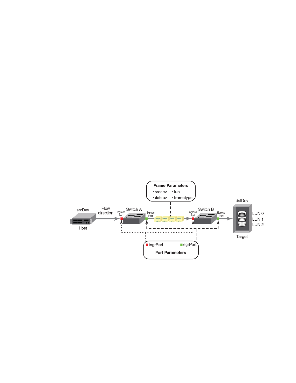
• Port parameters: (also called the Point of Interest, or where the data you want to examine is
from) This consists of an ingress port (ingrport) or an egress port (egrport). Only one can be
specified when defining a flow.
• Frame parameters: These are the following parameters: Source Device Identification (SID or
WWN), Destination Device Identification (DID or WWN), LUN, or frame type. At least one frame
parameter must be present to define a flow. Refer to Tab le 3 on page 4 for details on frame types.
• Direction: A direction is implicitly defined from an ingress port to an egress port, or a source
device (srcdev) to a destination device (dstdev). For example, srcdev=x, dstdev=y indicates
traffic flowing from x to y. The -bidir option causes the flow definition to be monitored in both
directions. This makes the following true:
- Entering srcdev=x dstdev=y specifies that only traffic flowing from x to y is the desired flow.
- Entering srcdev=x dstdev=y -bidir specifies that traffic travelling from x to y and traffic
travelling from y to x are both desired flows.
Figure 1 illustrates how the frame and port parameters apply to a flow.
FIGURE 1 Frame and port parameters
Flow definitions
To define a flow and configure Flow Vision to monitor that flow, you must provide a unique flow
name and specify the flow parameters. These parameters identify the sets of related frames and
can either be explicitly defined or Flow Vision can learn them through observation.
Flow definitions are stored on the switch on which the flow is created, and are not distributed
across the fabric. This means that each switch knows only its own flows and does not know what
flows exist on other switches.
2 Flow Vision Administrator’s Guide
53-1002999-01
Page 15

Flows
NOTE
1
When creating or viewing a flow, you can specify any combination of the three features in the flow
command. For example:
flow --create flowname -feature monitor,generator <parameters>
flow --show flowname -feature mirror,generator <parameters>
Flow definition rules
The rules listed in Table 1 identify what parameters can be used to define a flow.
TABLE 1 Flow definition rules
Parameters Field names Rules
Port ingrpor t
egrport
Frame srcdev
dstdev
lun
frametype
1. Refer to Table 3 for more information on frame types.
• One field only must be specified
• Values must be explicit
• At least one field must be specified
• Values for srcdev and dstdev can be explicit or “*” (“*” indicates learned flows)
• Values for lun and frametype must be explicit
1
Supported port configurations
Tab le 2 lists the supported configurations for each Flow Vision feature using only the basic flow
identification parameters (ingrport and srcdev, egrport and dstdev).
TABLE 2 Port configurations supported in Flow Vision
Feature Platforms Switch Configuration Mode
Flow Generator
Flow Mirror
Flow Monitor
16 Gbps-capable
Fibre Channel
Supported (SIM-Ports only) Supported
Supported (F_Ports only) Not Supported Not Supported Supported
Supported (E_Ports.
EX_Ports, and F_Ports only)
1
8 Gbps-capable Fibre Channel Access Gateway Virtual Fabric
Not Supported Supported
(Destination SIM-Ports only)
Supported (F_Ports only) Supported
(F_Ports only)
Supported
1. 16Gbps-capable platforms include the Brocade FC8-32E and FC8-48E blades.
If you are using at least one advanced parameter (lun, -frametype, or -bidir), then feature-specific
rules apply. Refer to the individual Flow Vision features for specific details.
Neither ranges nor lists are supported for any parameter.
Flow Vision Administrator’s Guide 3
53-1002999-01
Page 16

1
Flows
Flow frametype parameters
Frame monitoring can be done for a variety of frames using predefined -frametype parameters.
Tab le 3 list these parameters and the frames counted for each.
On 8 Gbps-capable Fibre Channel platforms, possible frame monitoring flow classifiers include
egrport, dstdev, and lun. On 16 Gbps-capable Fibre Channel platforms, including the Brocade
FC8-32E and FC8-48E blades, possible frame monitoring flow classifiers include ingrport, egrport,
dstdev, srcdev, and lun.
TABLE 3 Supported frametype parameters
Frametype parameter Frames counted
abts Abort Sequence
baacc All frames accepted
barjt All frames rejected
scsi All SCSI frames (including both command and data frames)
scsiread Only SCSI read command frames
scsiwrite Only SCSI write command frames
scsirw Both SCSI read and write command frames
scsi2reserve Only SCSI 2 reserve command frames
scsi3reserve Only SCSI 3 reserve command frames
scsi2release Only SCSI 2 release command frames
scsi3release Only SCSI 3 release command frames
scsi2reserverelease Only SCSI 2 reserve-release command frames
scsi3reserverelease Only SCSI 3 reserve-release command frames
scsitur Only SCSI test unit ready frames
scsistatus Only SCSI status frames
scsicmdsts
scsigoodstatus Only SCSI status frames with status marked as good (all 0s (zeros) in status byte)
scsicheckstatus Only SCSI status frames with check status
scsiinquiry Only SCSI inquiry frames
scsiresvconflict Only SCSI status frames with reservation conflict set
scsixferrdy Only SCSI FCP XFER_RDY (transfer ready) frames
1
Only SCSI command status frames
(Check Condition, Busy, Reservation Conflict, Task Full Set)
1. This parameter is valid only for Flow Mirror. It implicitly assumes -bidir and looks for both SCSI command and
status frames.
4 Flow Vision Administrator’s Guide
53-1002999-01
Page 17

Flows
1
Numbers of flows supported
Flow Vision supports a maximum of 512 flows on chassis-based platforms and a maximum of
128 flows on fixed-port platforms. However, there is a combined limit from all features of 64 flows
(including static flows, root flows, and sub-flows, whether active or inactive) for any one port. In
addition, there are individual limits for each Flow Vision feature; Ta ble 4 lists these limits.
A verification is done for each flow when it is created or activated to ensure that there is no
identical flow active. Refer to the limitations section of each feature for additional feature-specific
restrictions.
TABLE 4 Feature-specific flow count restrictions in Flow Vision
Feature Limit to number of flows
Flow Monitor Up to 64 active flows per port, including static flows, root flows, and sub-flows.
Flow Generator Up to 4 active flows per port, including static flows, root flows, and sub-flows.
Flow Mirror One active flow per port.
Flow learning
Flow Vision can create a learned flow by using an asterisk (*) for the source device, the destination
device, or both devices. This allows you to discover what flows are active on a port without having to
identify all the devices. Each Flow Vision feature uses learning as follows:
• Flow Monitor can learn all the source device and destination device pairs passing through the
ingress or egress port defined in a flow. Learning is not supported for Flow Monitor flows
defined using the lun, -frametype, or -bidir parameters. Refer to “Learning in Flow Monitor
flows” on page 12 for additional information.
• Flow Generator can generate traffic to or from every source or destination device that shares
the zone with the ingress or egress port defined in a flow. Refer to “Learning in Flow Generator
flows” on page 34 for additional information.
• Flow Mirror can capture all the source device and destination device pairs passing through the
ingress or egress port defined in a flow. Learning is supported for Flow Mirror flows defined
using the lun, -frametype, or -bidir parameters. Refer to “Learning in Flow Mirror flows” on
page 51 for additional information.
Flow Vision uses an asterisk (*) to indicate a learned flow. When you enter an asterisk as part of
the command, you must enclose it in double quotes (“*”).
Learning source device (srcdev) or destination device (dstdev) values is only supported on
16 Gbps-capable Fibre Channel ports.
Viewing flows
To display all Flow Vision flows, enter flow --show. To display all flows for a specific feature, enter
flow --show -feature featurename. To display the definition for a specific flow, enter flow --show
flowname -feature featurename. When you run flow --show with a flow name, then only the flow
definition for the specified flow is displayed. If the feature is also specified, feature-specific data is
displayed for the specified flow name. For root and static flows, this command shows the
Source ID-Destination ID pairs and the cumulative frame count on the ingress or egress port
specified in the flow definition.
Flow Vision Administrator’s Guide 5
53-1002999-01
Page 18

Flow Vision references
NOTE
1
The following example displays all the existing flows on the switch.
switch:admin> flow --show
-----------------------------------------------------------------------------------------------Flow Name | Feature | SrcDev | DstDev |IngrPt|EgrPt |BiDir| LUN | FrameType|
-----------------------------------------------------------------------------------------------local |gen |- |019200 |13 |- |no |- |- |
flow2 |gen+,mon+ |010900 |01c100 |1/9 |- |no |- |- |
flow1 |gen+,mon+ |01c100 |- |8/1 |- |no |- |- |
-----------------------------------------------------------------------------------------------+ Denotes feature is currently activated for the flow
Refer to the “viewing” section of each individual feature to see feature-specific output.
Flow Vision references
The following sections provide additional information about Flow Vision.
Roles and access in Flow Vision
Flow Vision can be accessed by users with the following roles: Admin, Switch Admin, or
Fabric Admin.
Flow Vision integration with MAPS
Statistics generated using Flow Vision can be monitored with the Monitoring and Alerting Policy
Suite (MAPS) threshold service. Refer to the MAPS section of each individual feature in this manual
for information on how that feature interacts with MAPS, and the Monitoring and Alerting Policy
Suite Administrator’s Guide for more details on MAPS in general.
Flow Vision licensing
To run Flow Vision, you need either the Fabric Vision (FV) license or both the Fabric Watch (FW) and
the Advanced Performance Monitor (APM) licenses. If you have both of these licenses, you do not
need a separate Flow Vision license. Refer to the Fabric OS Administrator’s Guide for more specific
information on licenses.
Flow Vision configuration setup
The Flow Vision configuration can be saved through the configdownload command and uploaded
through the configupload command. The configdefault command deletes all flows and simulation
ports (SIM-Ports) from the switch.
When a switch goes offline or comes online, Flow Vision reads the configuration files and then
deletes flows, creates flows, and activates flows. After a switch goes offline, any flows that were
active at the time it went offline will be reactivated when it comes back online and new traffic will
be generated as soon as the source and destination devices defined in the flow are online.
Statistical data for flows is not saved in the configuration database.
6 Flow Vision Administrator’s Guide
53-1002999-01
Page 19

Flow Vision references
NOTE
1
Firmware upgrading and downgrading and Flow Vision
There are no restrictions on upgrading the firmware of a switch that has Flow Vision installed.
Downgrading the firmware on a switch with Flow Vision installed will fail if any Flow Vision-related
configurations are present on the switch being downgraded. All Flow Vision-related flows or
simulation ports must be deleted prior to performing a downgrade to any version of Fabric OS prior
to version 7.2.0; if they are not, the downgrade will be blocked and a warning message displayed.
High Availability and Flow Vision
If a standby Command Processor (CP) with a down rev code comes online and any flows (active or
non-active) are configured, the HA will be out of sync. If a standby Command Processor (CP) with a
down rev code comes online and no flows (active or non-active) are configured, HA will be in sync
but flow creation will fail.
High Availability (HA) preserves only the Flow Vision configuration settings through an HA failover,
HA reboot, or a power cycle and reboot. It does not save feature-related data (for example,
statistics).
Refer to the individual feature’s HA section for information on how that feature is treated under HA:
• “Flow Monitor and High Availability” on page 29
• “Flow Generator and High Availability” on page 43
• “Flow Mirror and High Availability” on page 55
While disabling a SIM-Port that is receiving traffic may produce class 3 discards for the simulated
traffic, this will have no effect on other traffic flows.
Flow Vision Administrator’s Guide 7
53-1002999-01
Page 20

Flow Vision references
1
8 Flow Vision Administrator’s Guide
53-1002999-01
Page 21

ChapterX
Flow Monitor
In this chapter
•Overview of Flow Monitor . . . . . . . . . . . . . . . . . . . . . . . . . . . . . . . . . . . . . . . . . 9
•Flow Monitor management. . . . . . . . . . . . . . . . . . . . . . . . . . . . . . . . . . . . . . . 10
•Flow Monitor examples . . . . . . . . . . . . . . . . . . . . . . . . . . . . . . . . . . . . . . . . . . 13
•Monitoring Fibre Channel routed fabrics . . . . . . . . . . . . . . . . . . . . . . . . . . . . 19
•Flow Monitor references . . . . . . . . . . . . . . . . . . . . . . . . . . . . . . . . . . . . . . . . . 29
Overview of Flow Monitor
Flow Monitor provides you with the following abilities:
• Comprehensive visibility into application flows in the fabric, including the ability to learn
(discover) flows automatically.
• Monitoring of application flows (for example: a flow within a fabric from a Host to a Target/LUN)
at a given port.
• Capture of statistics for specified flows, providing insights into application performance. These
statistics include: transmitted and received frame counts, transmitted and received frame
throughput rates, SCSI Read and SCSI Write frame counts, the number of SCSI Reads and
Writes per second (IOPS), as well as others.
• When N_Port ID Virtualization (NPIV) is used on the host, users can monitor VM (Virtual
Machine) to LUN level performance as well.
• Monitoring of various frame types at a switch port to provide deeper insights into storage I/O
access pattern at a LUN, reservation conflicts, and I/O errors. For example: SCSI Aborts,
SCSI Read, SCSI Write, SCSI Reserve, all rejected frames, and many others. See Table 3 on
page 4 for a list and description of the frame types that can be monitored.
• Integration with the Monitoring and Alerting Policy Suite (MAPS) service to enable
threshold-based monitoring and alerting for flows.
2
A sample use case would be to monitor throughput statistics for inbound traffic between a source
device and a destination device. “Monitoring LUN level statistics” on page 13 provides an example
of the command and the results for this use case.
The existing Advanced Performance Monitor provides the following monitors: End-to-End,
Frame-based, ISL, and Top Talker. Flow Monitor expands on these options by allowing you to
monitor any hardware-supported flow parameters and define your own flows using combinations of
ingress and egress ports, source and destination devices, LUNs, and frame types as parameters to
create a flow definition for a specific use case.
For information on replicating standard Advanced Performance Monitor functionality using
Flow Monitor, refer to “End-to-end monitor”, “Frame monitor”, and “Ingress or egress Top Talker
monitor” on page 15.
Flow Vision Administrator’s Guide 9
53-1002999-01
Page 22

Flow Monitor management
ATTENTION
2
Flow Monitor management
The following sections describe how to manage the Flow Monitor feature.
Creating Flow Monitor flows
To create a Flow Monitor flow, enter the flow --create flowname -feature monitor parameters
command using the parameters in Table 5. Figure 1 on page 2 illustrates how the frame and port
parameters apply to a flow.
Tab le 5 shows the supported Flow Monitor flow parameter combinations.
TABLE 5 Flow Monitor flow parameter combinations
Parameters Field names Description
Port ingrpor t
egrport
Frame srcdev
dstdev
lun
frametype
Optional keyword parameters
-bidir Adding this keyword makes the application monitor traffic in both directions.
-noactivate Adding this keyword creates the flow without activating it.
-noconfig Adding this keyword creates the flow without saving the flow to the configuration.
• One field only must be specified
• Values must be explicit
• Can be an F-Port, E-Port, or EX-Port on a local switch
• At least one field must be specified
• Values for srcdev and dstdev can be explicit or “*” (“*” indicates learned flows)
• Values for lun and frametype must be explicit
Parameter usage exceptions
The following restrictions apply to parameter usage in Flow Monitor flow definitions:
• The -lun and -bidir parameters cannot be used together in a flow definition.
• Flow Monitor does not support learning flows using the -frametype, -lun, or -bidir parameters.
The following example creates a Flow Monitor flow named “Flow1” that monitors all traffic flowing
from device 010403 to device 020504 ingressing through port 10 on the switch on which this
command was run.
switch:admin> flow --create Flow1 -feature monitor -ingrport 10 -srcdev 010403 -dstdev 020504
When you create a flow, it is automatically activated unless you use the -noactivate keyword as part
of the flow --create command. Refer to “Creating an inactive flow in Flow Monitor” on page 11 for
an example of this option.
Flow creation is not allowed if Advanced Performance Monitor or Port Mirroring is enabled. Similarly,
APM and Port Mirroring-related operations will not be allowed if any flow (active or defined) is
present on the switch.
10 Flow Vision Administrator’s Guide
53-1002999-01
Page 23

Flow Monitor management
Creating an inactive flow in Flow Monitor
To create an inactive Flow Monitor flow, enter the flow --create command with the -noactivate
keyword.
flow --create flowname -feature monitor flow_parameters -noactivate
Refer to “Activating Flow Monitor flows” on page 11 for information on activating a Flow Monitor
flow. The following example creates an inactive Flow Monitor flow named “sflow8” from
device 020a00 to device 01c000 ingressing through port 10.
switch:admin> flow --create sflow8 -feature mirror -ingrport 10 -srcdev 0x020a00 -dstdev 0x01c000
-noactivate
Activating Flow Monitor flows
To activate an inactive Flow Monitor flow, enter flow --activate flowname -feature monitor.
Activating a flow automatically clears all the flow statistics for that flow. The following example
activates the Flow Monitor flow named “Flow1”.
switch:admin> flow --activate Flow1 -feature monitor
Automatic activation of a Flow Monitor flow
2
Flow Monitor automatically activates monitoring flows under the following conditions:
• On flow creation unless the flow is created using the -noactivate keyword.
• On slot power-on, if any of the ports or devices defined in the flow are on the slots being
powered on. This assumes that the flow was active when the slots were powered off.
• On a High Availability (HA) failover, HA reboot, or a power cycle, if the flow was active when the
event occurred.
Deactivating Flow Monitor flows
To deactivate a Flow Monitor flow, enter flow --deactivate flowname -feature monitor. The following
example deactivates the Flow Monitor flow named “Flow1”.
switch:admin> flow --deactivate Flow1 -feature monitor
Automatic deactivation of a Flow Monitor flow
Flow Vision automatically deactivates all Flow Monitor flows if any of the following occur:
• Slot is powered off for the ingress or egress ports defined in the flow.
• Slot is powered off for the source or destination devices defined in the flow.
• The ingress or egress port type changes to anything other than an F_Port or SIM-Port for a
learned flow (“*”). The flow will not automatically reactivate if the port type is changed back.
You must manually reactivate this flow.
• The ingress or egress port type changes to anything other than an F_Port or SIM-Port for a flow
that has a lun or frametype value specified. The flow will not automatically reactivate if the port
type is changed back. You must manually reactivate this flow.
Flow Vision Administrator’s Guide 11
53-1002999-01
Page 24

Flow Monitor management
2
Viewing Flow Monitor flows
To display Flow Monitor flows, enter flow --show flowname -feature monitor. The displayed
information includes:
• Frame Statistics: Frame count and rate for the flow-defined frame type
• Throughput Statistics: Word count and throughput (bytes per second)
• I/O Statistics: I/O count, IO per second and I/O data transferred on a read/write basis
• Learn Statistics: All learned (“*”) flows on a given F_Port and the throughput and frame
statistics for each learned flow on 16 Gbps-capable Fibre Channel platforms
For illustrations of flow --show command output, refer to “Flow Monitor examples” on page 13.
Repeating Flow Monitor output
To specify the number of times the output should be repeated, enter the flow --show flowname
-feature monitor command with the -count num parameter. The num value can range from 1
through 10. The default value is 1.
flow --create flowname -feature monitor flow_parameters -count num
Sorting Flow Monitor output
To sort the data output for a flow, enter the flow --show flowname -feature monitor command with
the -sortby column_num parameter. The column_num value is the number of the output column on
which the data is to be sorted.
flow --create flowname -feature monitor flow_parameters -sortby column_num
In Flow Monitor, frames can be sorted whether or not sub-flows are present. The -sortby parameter
can only be applied when there is only one feature specified in the flow --show flowname command.
Learning in Flow Monitor flows
To apply learning to a Flow Monitor flow, use an asterisk inside quotation marks (“*”) to specify the
parameter to be learned. The following example creates a Flow Monitor learning flow named
“IngressTT” ingressing through port 30. Refer to “Monitoring flows using the learning functionality”
on page 14 to view how the data captured using this flow is displayed.
switch:admin> flow --create ingressTT –feature monitor –ingrport 30 –srcdev "*" -dstdev "*"
Only 16 Gbps-capable Fibre Channel platforms have the capability to learn flows on a specified
port, and learning is possible on F_Ports only. Only one active flow per ASIC can be a learning flow.
Deleting Flow Monitor flows
To delete a flow, enter flow --delete flowname. The following example deletes a Flow Monitor flow
named “Flow1”.
switch:admin> flow --delete Flow1
You do not need to include -feature monitor, as you can only delete the entire flow; you cannot
delete an individual feature from a flow. Deleting a flow automatically clears all the flow statistics
for that flow. Deleting a flow removes all instances of that flow; you cannot delete an individual
feature from a flow. Deleting an active flow automatically deactivates the flow before it is deleted.
12 Flow Vision Administrator’s Guide
53-1002999-01
Page 25

Resetting Flow Monitor flow statistics
To clear the statistics for a Flow Monitor flow, enter flow --reset flowname -feature monitor. The
following example clears the statistics for the Flow Monitor flow named “Flow1”.
switch:admin> flow --reset Flow1 -feature monitor
Flow Monitor examples
The following examples display how to use the Flow Monitor feature.
• Monitoring LUN level statistics
• Viewing summary flow data for a specific device pair
• Monitoring flows using the learning functionality
• End-to-end monitor
• Frame monitor
• Ingress or egress Top Talker monitor
• Monitoring Fibre Channel routed fabrics
Flow Monitor examples
2
Monitoring LUN level statistics
A common use of flow monitors is to monitor traffic flowing from a particular ingress port to a
specified LUN. The following example creates a flow named “lunFlow1” which monitors traffic
ingressing on port 5 between device 010502 and device 030700 that uses lun 4, and then
displays the results of that flow. Figure 2 provides an illustration of what is happening in the
example.
FIGURE 2 A LUN monitoring flow
switch:admin> flow --create lunFlow1 -feature monitor -ingrport 5 -srcdev 0x010502 -dstdev 0x030700
switch:admin> flow --show lunFlow1 -feature monitor
Name : lunflow1 Features: mon(Activated) noConfig: off
Definition: IngrPort(5),SrcDev(010502),DstDev(030700),Lun(4)
Flow Monitor (Activated):
Monitor time: | Thu Jun 06 15:15:39 UTC 2013 |
-------------------------------------------------------------------------------------------------
-lun 4
Flow Vision Administrator’s Guide 13
53-1002999-01
Page 26

Flow Monitor examples
2
| I/O Count | I/O Per Sec.(IOPS) | I/O bytes Transferred | I/O bytes Per Sec. |
| Reads / Writes/ Total | Reads / Writes/ Total | Reads / Writes/ Total | Reads / Writes/ Total |
-------------------------------------------------------------------------------------------------
| 44.92k/ 44.94k/ 89.85k| 2.00k/ 2.00k/ 4.01k| 5.88M/ 5.89M/ 11.77M| 2.62M/ 2.62M/ 5.25M|
-------------------------------------------------------------------------------------------------
Viewing summary flow data for a specific device pair
The following example creates a Flow Monitor flow gathering statistics for frames ingressing
through port 30 between device 010000 and device 010100, and then displays the results.
The point of interest in this example is port 30; it can be either an E, EX, or F_Port.
switch:admin> flow --create sumflow1 -feature monitor -ingrport 30 -srcdev 010000 -dstdev 010100
switch:admin> flow --show
------------------------------------------------------------------------------------- \
Flow Name | Feature | SrcDev | DstDev \
------------------------------------------------------------------------------------- \
sumflow1 |mon+ |010000 |010100 \
------------------------------------------------------------------------------------- \
-------------------------------------IngrPt|EgrPt |BiDir| LUN | FrameType|
30 |- |no |- |- |
+ Denotes feature is currently activated for the flow
--------------------------------------
switch:admin> flow --show sumflow1 -feature monitor
==================================================================================================
Name : sumflow1 Features: mon(Active) noConfig: Off
Definition: IngrPort(30),SrcDev(0x010000),DstDev(0x010100)
Flow Monitor (Activated):
Monitor time: | Tue Jul 16 22:06:32 CLT 2013 |
---------------------------------------------------------
-----------------------------------------------------------------------------------------------------
| Rx Frames Count | Rx Frames per Sec. | Rx Bytes Count | Rx Throughput(Bps) | Avg Rx Frm Sz(Bytes)|
-----------------------------------------------------------------------------------------------------
| 4.83G | 10.62M | 617.07G | 1.34G | 140 |
-----------------------------------------------------------------------------------------------------
-------------------------------------------------------------------------------------------------
| I/O Count | I/O Per Sec.(IOPS) | I/O bytes Transferred | I/O bytes Per Sec. |
| Reads / Writes/ Total | Reads / Writes/ Total | Reads / Writes/ Total | Reads / Writes/ Total |
-------------------------------------------------------------------------------------------------
| 4.88G/ 0 / 4.88G| 10.62M/ 0 / 10.62M| 21.79T/ 0 / 21.79T|559.59M/ 0 /559.59M|
-------------------------------------------------------------------------------------------------
=================================================================================================
Monitoring flows using the learning functionality
The following example illustrates using the learning functionality for flow monitoring. The defined
flow will monitor for frames ingressing on port 30 between all devices.
switch:admin> flow --create ingressTT –feature monitor –ingrport 30 –srcdev "*" –dstdev "*"
switch:admin> flow --show
-------------------------------------------------------------------------------------\
Flow Name | Feature | SrcDev | DstDev \
-------------------------------------------------------------------------------------\
ingressTT |mon+ |* |* \
14 Flow Vision Administrator’s Guide
53-1002999-01
Page 27

Flow Monitor examples
-------------------------------------------------------------------------------------\
--------------------------------------|IngrPt|EgrPt |BiDir| LUN | FrameType|
|30 |- |no |- |- |
---------------------------------------
+ Denotes feature is currently activated for the flow
switch:admin> flow --show ingressTT -feature monitor
===============================================================================================
Name : ingresstt Features: mon(Active) noConfig: Off
Definition: IngrPort(30),SrcDev(*),DstDev(*)
Flow Monitor (Activated):
Monitor time: | Tue Jul 16 06:12:12 CLT 2013 |
---------------------------------------------------------
-------------------------------------------------------------------------------------------- \
|SID(*)|DID(*)| Rx Frames Count | Rx Frames per Sec. | Rx Bytes Count | Rx Throughput(Bps) \
-------------------------------------------------------------------------------------------- \
|010000|010100| 9.92G | 201.22k | 18.87T | 399.93M \
|010000|010200| 9.92G | 201.23k | 18.87T | 399.93M \
|010000|010300| 9.92G | 201.23k | 18.87T | 399.93M \
|010000|010400| 9.92G | 201.22k | 18.87T | 399.93M \
-------------------------------------------------------------------------------------------- \
| *| *| 39.69G | 804.91k | 75.48T | 1.56G \
-------------------------------------------------------------------------------------------- \
============================================================================================ \
-----------------------| Avg Rx Frm Sz(Bytes)|
-----------------------| 2092 |
| 2092 |
| 2092 |
| 2092 |
| 2092 |
-----------------------========================
The Flow Vision interface provides a single interface for flow management that unifies legacy use
cases such as end-to-end (EE) monitors, frame monitors, and so on. The following examples show
how to implement the equivalent functionality using Flow Monitor.
2
End-to-end monitor
You can use the -bidir keyword to create the equivalent to an end-to-end monitor. The following
example creates a bidirectional Flow Monitor flow between device 02d8c0 and device 023a00
egressing port 4/10 of the switch on which the command is running.
switch:admin> flow --create endtoendflow -feature monitor -egrport 4/10 -dstdev 023a00 -srcdev 02d8c0
-bidir
switch:admin> flow --show endtoendflow
=================================================================================
Name : endtoendflow Features: mon(Activated) noConfig: Off
Definition: EgrPort(4/10),SrcDev(0x02d8c0),DstDev(0x023a00),BiDir
Flow Monitor (Activated):
Monitor time: | Fri Aug 30 22:52:35 UTC 2013 |
---------------------------------------------------------
-------------------------------------------------------------------------------------------------\
| Frame Count | Frames Per Sec. | Byte count | Throughput(Bps) \
| Tx / Rx / Total | Tx / Rx / Total | Tx / Rx / Total | Tx / Rx / Total \
Flow Vision Administrator’s Guide 15
53-1002999-01
Page 28

Flow Monitor examples
2
-------------------------------------------------------------------------------------------------\
| 65.11M/129.63M/194.75M|962.52k/653.84k/ 1.61M| 99.49G/185.44G/284.93G|958.32M/957.77M/ 1.87G \
-------------------------------------------------------------------------------------------------\
------------------|Frame Size(Bytes)|
|Tx/Rx|
| 1632 / 1528 |
-------------------
-------------------------------------------------------------------------------------------------
| I/O Count | I/O Per Sec.(IOPS) | I/O bytes Transferred | I/O bytes Per Sec. |
| Reads / Writes/ Total | Reads / Writes/ Total | Reads / Writes/ Total | Reads / Writes/ Total |
-------------------------------------------------------------------------------------------------
| 3.19M/ 24.14M/ 27.33M|481.13k/481.13k/962.27k|176.56G/ 1.30T/ 1.47T| 2.61G/ 2.61G/ 1.22G|
-------------------------------------------------------------------------------------------------
=================================================================================================
Frame monitor
You can use the -frametype parameter to create the equivalent to using the fmmonitor command.
The following example creates a Flow Monitor flow that counts SCSI Read-Write (scsirw) frames
egressing port 2 of the switch on which the command is running.
switch:admin> flow --create scsirw -fe mon -egrport 2 -frametype scsirw
Monitor feature(s) have been activated.
switch:admin> flow --show
--------------------------------------------------------------------------------------------------------\
Flow Name | Feature | SrcDev | DstDev |IngrPt|EgrPt |BiDir\
--------------------------------------------------------------------------------------------------------\
f1 |mon |030300 |030400 |3 |- |no \
lrn0 |mon+ |* |* |0 |- |no \
lrn89 |mon+ |* |* |89 |- |no \
scsirw |mon+ |- |- |- |2 |no \
--------------------------------------------------------------------------------------------------------\
+ Denotes feature is currently activated for the flow
------------------| LUN | FrameType|
-------------------|0 |- |
|- |- |
|- |- |
|- |srdwr |
switch:admin> flow --show scsirw
=========================================================================================================
Name : scsirw Features: mon(Activated) noConfig: Off
Definition: EgrPort(2),FrameType(srdwr)
--------------------
Flow Monitor (Activated):
Monitor time: | Fri Aug 30 23:31:04 UTC 2013 |
---------------------------------------------------------
-----------------------------------------
| Tx Frames Count | Tx Frames per Sec. |
-----------------------------------------
| 10.27M | 327.55k |
-----------------------------------------
=========================================================================================================
16 Flow Vision Administrator’s Guide
53-1002999-01
Page 29

Flow Monitor examples
2
Ingress or egress Top Talker monitor
You can use the learn flow (“*”) parameter to create the equivalent to a Top Talker monitor. A Top
Talker monitor is used to identify high volume flows passing a port. This monitor is only supported
on F_Ports. The following example creates both an ingress and an egress Top Talker monitor. The
first command creates a Flow Monitor learning flow named “ingresstt” for all frames between any
devices ingressing through port 41 of the switch on which the command is running. The second
command creates a Flow Monitor learning flow named “egresstt” for all frames between any
devices egressing through port 30 of the switch on which the command is running.
switch:admin> flow --create ingresstt -feature monitor -ingrport 41 -srcdev "*" -dstdev "*"
Monitor feature(s) have been activated.
switch:admin> flow --create egresstt -feature monitor -egrport 30 -srcdev "*" -dstdev "*"
Monitor feature(s) have been activated.
switch:admin> flow --show
--------------------------------------------------------------------------------------------------------\
Flow Name | Feature | SrcDev | DstDev |IngrPt|EgrPt |BiDir\
--------------------------------------------------------------------------------------------------------\
ingresstt |mon+ |* |* |41 |- |no \
egresstt |mon+ |* |* |30 |- |no \
--------------------------------------------------------------------------------------------------------\
+ Denotes feature is currently activated for the flow
-----------------| LUN | FrameType|
|- |- |
|- |- |
=========================================================================================================
------------------
switch:admin> flow --show ingresstt
=========================================================================================================
Name : ingresstt Features: mon(Activated) noConfig: Off
Definition: IngrPort(41),SrcDev(*),DstDev(*)
Flow Monitor (Activated):
Monitor time: | Fri Aug 30 23:44:58 UTC 2013 |
---------------------------------------------------------
--------------------------------------------------------------------------------------------\
|SID(*)|DID(*)| Rx Frames Count | Rx Frames per Sec. | Rx Bytes Count | Rx Throughput(Bps) \
--------------------------------------------------------------------------------------------\
|012900|051e00| 3.97M | 112.68k | 5.68G | 165.06M \
|012900|020600| 7.95M | 225.64k | 15.09G | 438.13M \
|012900|010700| 4.52M | 128.62k | 4.36G | 127.08M \
|012900|020900| 7.90M | 224.21k | 11.31G | 328.43M \
--------------------------------------------------------------------------------------------\
| *| *| 24.36M | 691.16k | 36.44G | 1.03G \
--------------------------------------------------------------------------------------------\
=========================================================================================================
----------------------| Avg Rx Frm Sz(Bytes)|
----------------------| 1536 |
| 2036 |
| 1036 |
| 1536 |
| 1606 |
----------------------=======================
Flow Vision Administrator’s Guide 17
53-1002999-01
Page 30

Flow Monitor examples
2
switch:admin> flow --show egresstt
========================================================================================================
Name : egresstt Features: mon(Activated) noConfig: Off
Definition: EgrPort(0/30),SrcDev(*),DstDev(*)
Flow Monitor (Activated):
Monitor time: | Fri Aug 30 23:25:35 UTC 2013 |
---------------------------------------------------------
--------------------------------------------------------------------------------------------\
|SID(*)|DID(*)| Tx Frames Count | Tx Frames per Sec. | Tx Bytes Count | Tx Throughput(Bps) \
--------------------------------------------------------------------------------------------\
|022900|051e00| 7.99M | 1.86k | 9.19G | 2.19M \
|012c00|051e00| 4.50M | 1.04k | 4.35G | 1.03M \
|022800|051e00| 7.99M | 1.86k | 7.71G | 1.83M \
|012a00|051e00| 2.25M | 524 | 3.22G | 787.35k \
|022a00|051e00| 7.38M | 1.71k | 14G | 3.33M \
|012b00|051e00| 4.50M | 1.04k | 4.35G | 1.03M \
|012900|051e00| 2.25M | 524 | 4.27G | 1.01M \
--------------------------------------------------------------------------------------------\
| *| *| 36.89M | 8.58k | 47.11G | 11.23M \
--------------------------------------------------------------------------------------------\
----------------------| Avg Tx Frm Sz(Bytes)|
----------------------| 1236 |
| 1036 |
| 1036 |
| 1532 |
| 2032 |
| 1036 |
| 2032 |
----------------------| 1368 |
-----------------------
Note: Statistics are provided for the aggregate traffic generated to the specified SIM-port. No traffic is
actually transmitted out on the SIM-port.
=========================================================================================================
Configuring Flow Monitor for a trunk group
Flow Monitor supports monitoring trunk ports subject to the following conditions:
• You must create the same flow on all trunk member ports.
• If you create a flow on a slave port without using the -noactivate keyword, this flow is
automatically activated when the slave port becomes the master port.
• After a switch initialization or a recovery (cold or warm), existing flows are re-created on both
master and slave ports, but only those flows associated with the master port are activated.
To configure Flow Monitor on a trunk group, use the following steps:
1. Identify your trunk group members using the switchshow command.
2. Create individual flow monitors for each member of the trunk group.
To view the Flow Monitor statistical data for the entire trunk group, enter flow --show flowname
-feature monitor. The accumulated Flow Monitor statistical data for the entire trunk group is stored
on the master port. If the master port changes, the data is transferred to the new master port. To
view this data, you must run flow --show on a flow that is defined using the master port.
Flow statistics are not displayed for slave trunk ports.
18 Flow Vision Administrator’s Guide
53-1002999-01
Page 31

Monitoring Fibre Channel routed fabrics
NOTE
You cannot create a learned flow in a trunk group.
The following example displays the trunked ports and then creates four flows, one for each member
of the trunk group identified by the switchshow command.
switch:admin> switchshow
24 24 021800 id N16 Online FC E-Port 10:00:00:05:33:e5:3c:d4 "Odin" (downstream)(Trunk master)
25 25 021900 id N16 Online FC E-Port (Trunk port, master is Port 24 )
26 26 021a00 id N16 Online FC E-Port (Trunk port, master is Port 24 )
27 27 021b00 id N16 Online FC E-Port (Trunk port, master is Port 24 )
switch:admin> flow -create f1 -feature monitor -egrport 24 -srcdev 022b00 -dstdev 033a00
switch:admin> flow -create f2 -feature monitor -egrport 25 -srcdev 022b00 -dstdev 033a00
switch:admin> flow -create f3 -feature monitor -egrport 26 -srcdev 022b00 -dstdev 033a00
switch:admin> flow -create f4 -feature monitor -egrport 27 -srcdev 022b00 -dstdev 033a00
Monitoring Fibre Channel routed fabrics
When creating flow monitors on EX_Ports, you can use either a WWN or a Fibre Channel ID (FCID) for the
source device (srcdev) and destination device (dstdev). Inter-Fabric Link (IFL) flows can be monitored
only on 16 Gbps-capable EX_Ports in a Fibre Channel router. IFL flows are not supported on E_Ports or
F_Ports.
2
Even though a flow definition is always created in the backbone fabric, the perspective of the flow
is from the edge fabric. In the following examples, the flow definitions are based on the Edge 1
Fabric’s perspective.
When monitoring an FC router fabric, you may find it simpler to use port WWNs rather than proxy
IDs in your flow definitions. This is because you do not need to locate and map the proxy IDs for the
actual source and destination devices.
Monitoring FC router fabrics using port WWNs
The following examples present the flow definitions using deviceidmode set to WWN mode.
flow --control -deviceidmode wwn
FIGURE 3 An FC router fabric
Flow Vision Administrator’s Guide 19
53-1002999-01
Page 32

Monitoring Fibre Channel routed fabrics
2
In Figure 3, the physical devices are A, B, and C, and have the port WWNs a, b, and c, respectively.
Figure 4 provides the port WWN values for the following examples.
FIGURE 4 An FC router fabric annotated with port WWN values
Edge-to-edge through an ingress port
To monitor a flow from Device A to Device B ingressing through EX_Port1, the source device
(srcdev) is “Port WWN a”, the destination device (dstdev) is “Port WWN b”, and the ingress port
(ingrport) is EX_Port1 (Traffic is running from left to right).
The following example creates a flow that filters frames passing from one edge fabric to another
edge fabric using a specific ingress port on the backbone. The first command shows the available
ports and the available FC routers. The second command creates a Flow Monitor flow named
“e2e_src_dcx_wwn” between device 10:00:00:05:1e:e8:e2:00 and device
20:00:00:11:0d:e4:18:00 ingressing through port 219, and the last command displays the results
of the flow.
DCX_Backbone128:admin> switchshow |grep Port
Index Slot Port Address Media Speed State Proto
37 3 5 012500 id N16 Online FC EX-Port 10:00:00:05:33:ef:f1:1c
"Wasp_edge2" (fabric id = 50 )(Trunk master)
47 3 15 012f00 id N8 Online FC F-Port 20:02:00:11:0d:51:00:00
219 10 27 01db00 id N16 Online FC EX-Port 10:00:00:05:33:ee:d0:a5
"Honeybee_edge1" (fabric id = 100 )(Trunk master)
E-Port 50:00:51:e4:91:9e:0f:28 "fcr_xd_2_100"
DCX_Backbone128:admin> flow --create e2e_src_dcx_wwn -feature monitor -ingrport 219
DCX_Backbone128:admin> flow --show
-------------------------------------------------------------------------------------\
Flow Name | Feature | SrcDev | DstDev \
-------------------------------------------------------------------------------------\
e2e_src_dcx_wwn |mon+ |10:00:00:05:1e:e8:e2:00|20:00:00:11:0d:e4:18:00 \
-------------------------------------------------------------------------------------\
+ Denotes feature is currently activated for the flow
-srcdev 10:00:00:05:1e:e8:e2:00 -dstdev 20:00:00:11:0d:e4:18:00
--------------------------------------|IngrPt|EgrPt |BiDir| LUN | FrameType|
|219 |- |no |- |- |
---------------------------------------
DCX_Backbone128:admin> flow --show e2e_src_dcx_wwn -feature monitor
=========================================================================================================
Name : e2e_src_dcx_wwn Features: mon(Active) noConfig: Off
20 Flow Vision Administrator’s Guide
53-1002999-01
Page 33

Monitoring Fibre Channel routed fabrics
Definition: IngrPort(219),SrcDev(10:00:00:05:1e:e8:e2:00),DstDev(20:00:00:11:0d:e4:18:00)
Flow Monitor (Activated):
Monitor time: | Mon Jun 17 14:59:58 UTC 2013 |
---------------------------------------------------------
-----------------------------------------------------------------------------------------------------
| Rx Frames Count | Rx Frames per Sec. | Rx Bytes Count | Rx Throughput(Bps) | Avg Rx Frm Sz(Bytes)|
-----------------------------------------------------------------------------------------------------
| 2.85G | 8.44M | 387.88G | 1.12G | 132 |
-----------------------------------------------------------------------------------------------------
Edge-to-edge through an egress port
To monitor a flow from Device B to Device A egressing through EX_Port1, the source device (srcdev)
is “Port WWN b”, the destination device (dstdev) is “Port WWN a”, and the egress port (egrport) is
EX_Port1 (Traffic is running from right to left).
The following example creates a flow that filters out frames passing from one edge fabric to
another edge fabric using a specific egress port on the backbone. The first command shows the
available ports and the available FC routers. The second command creates a Flow Monitor flow
named “e2e_dst_dcx” between device 20:00:00:11:0d:e4:18:00 and device
10:00:00:05:1e:e8:e2:00 egressing through port 219, and the last command displays the results
of the flow.
DCX_Backbone128:admin> switchshow |grep Port
Index Slot Port Address Media Speed State Proto
37 3 5 012500 id N16 Online FC EX-Port 10:00:00:05:33:ef:f1:1c
"Wasp_edge2" (fabric id = 50 )(Trunk master)
47 3 15 012f00 id N8 Online FC F-Port 20:02:00:11:0d:51:00:00
219 10 27 01db00 id N16 Online FC EX-Port 10:00:00:05:33:ee:d0:a5
"Honeybee_edge1" (fabric id = 100 )(Trunk master)
E-Port 50:00:51:e4:91:9e:0f:28 "fcr_xd_2_100"
2
DCX_Backbone128:admin> flow --create e2e_dst_dcx -feature monitor -egrport 219
-srcdev 20:00:00:11:0d:e4:18:00 -dstdev 10:00:00:05:1e:e8:e2:00
DCX_Backbone128:admin> flow --show
----------------------------------------------------------------------------------------------------- \
Flow Name | Feature | SrcDev | DstDev |IngrPt|EgrPt |BiDir| LUN \
----------------------------------------------------------------------------------------------------- \
e2e_dst_dcx |mon+ |20:00:00:11:0d:e4:18:00|10:00:00:05:1e:e8:e2:00|- |219 |no |- \
----------------------------------------------------------------------------------------------------- \
-----------| FrameType|
|- |
+ Denotes feature is currently activated for the flow
DCX_Backbone128:admin> flow --show e2e_dst_dcx -feature monitor
=========================================================================================================
Name : e2e_dst_dcx Features: mon(Active) noConfig: Off
Definition: EgrPort(219),SrcDev(20:00:00:11:0d:e4:18:00),DstDev(10:00:00:05:1e:e8:e2:00)
Flow Monitor (Activated):
Monitor time: | Mon Jun 17 14:59:58 UTC 2013 |
---------------------------------------------------------
----------------------------------------------------------------------------------------------------| Tx Frames Count | Tx Frames per Sec. | Tx Bytes Count | Tx Throughput(Bps) | Avg Tx Frm Sz(Bytes)|
----------------------------------------------------------------------------------------------------| 2.85G | 8.44M | 387.88G | 1.12G | 132 |
-----------------------------------------------------------------------------------------------------
-----------
Flow Vision Administrator’s Guide 21
53-1002999-01
Page 34

Monitoring Fibre Channel routed fabrics
2
Backbone-to-edge
To monitor a flow from Device C to Device A egressing through EX_Port1, the source device (srcdev)
is “Port WWN c”, the destination device (dstdev) is “Port WWN a”, and the egress port (egrport) is
EX_Port1 (Traffic is running from right to left).
The following example creates a flow that filters out frames passing from the backbone fabric to an
edge fabric using a specific egress port. The first command shows the available ports and the
available FC routers. The second command creates a Flow Monitor flow named “b2e_dst_dcx”
between device 20:02:00:11:0d:51:00:00 and device 10:00:00:05:1e:e8:e2:00 egressing through
port 219, and the last command displays the results of the flow.
DCX_Backbone128:admin> switchshow |grep Port
Index Slot Port Address Media Speed State Proto
37 3 5 012500 id N16 Online FC EX-Port 10:00:00:05:33:ef:f1:1c
"Wasp_edge2" (fabric id = 50 )(Trunk master)
47 3 15 012f00 id N8 Online FC F-Port 20:02:00:11:0d:51:00:00
219 10 27 01db00 id N16 Online FC EX-Port 10:00:00:05:33:ee:d0:a5
DCX_Backbone128:admin> flow --create b2e_dst_dcx -feature monitor -egrport 219
"Honeybee_edge1" (fabric id = 100 )(Trunk master)
E-Port 50:00:51:e4:91:9e:0f:28 "fcr_xd_2_100"
-srcdev 20:02:00:11:0d:51:00:00 -dstdev 10:00:00:05:1e:e8:e2:00
DCX_Backbone128:admin> flow --show
---------------------------------------------------------------------------------------------------- \
Flow Name | Feature | SrcDev | DstDev |IngrPt|EgrPt |BiDir| LUN \
---------------------------------------------------------------------------------------------------- \
b2e_dst_dcx |mon+ |20:02:00:11:0d:51:00:00|10:00:00:05:1e:e8:e2:00 |- |219 |no |- \
---------------------------------------------------------------------------------------------------- \
-----------| FrameType|
|- |
+ Denotes feature is currently activated for the flow
DCX_Backbone128:admin> flow --show b2e_dst_dcx -feature monitor
=========================================================================================================
Name : b2e_dst_dcx Features: mon(Active) noConfig: Off
Definition: EgrPort(219),SrcDev(20:02:00:11:0d:51:00:00),DstDev(10:00:00:05:1e:e8:e2:00)
Flow Monitor (Activated):
Monitor time: | Mon Jul 17 15:59:58 UTC 2013 |
---------------------------------------------------------
----------------------------------------------------------------------------------------------------| Tx Frames Count | Tx Frames per Sec. | Tx Bytes Count | Tx Throughput(Bps) | Avg Tx Frm Sz(Bytes)|
----------------------------------------------------------------------------------------------------| 142.93M | 3.74M | 26.97G | 724.78M | 204 |
-----------------------------------------------------------------------------------------------------
-----------
22 Flow Vision Administrator’s Guide
53-1002999-01
Page 35

Monitoring Fibre Channel routed fabrics
2
Edge-to-backbone
To monitor a flow from Device A to Device C ingressing through EX_Port1, the source device
(srcdev) is “Port WWN a”, the destination device (dstdev) is “Port WWN c”, and the ingress port
(ingrport) is EX_Port1 (Traffic is running from left to right).
The following example creates a flow that filters out frames passing from an edge fabric to the
backbone fabric using a specific ingress port. The first command shows the available ports and the
available FC routers. The second command creates a Flow Monitor flow named “e2b_src_dcx”
between device 10:00:00:05:1e:e8:e2:00 and device 20:02:00:11:0d:51:00:00 egressing through
port 219, and the last command displays the results of the flow.
DCX_Backbone128:admin> switchshow |grep Port
Index Slot Port Address Media Speed State Proto
37 3 5 012500 id N16 Online FC EX-Port 10:00:00:05:33:ef:f1:1c "Wasp_edge2"
(fabric id = 50 )(Trunk master)
47 3 15 012f00 id N8 Online FC F-Port 20:02:00:11:0d:51:00:00
219 10 27 01db00 id N16 Online FC EX-Port 10:00:00:05:33:ee:d0:a5 "Honeybee_edg
DCX_Backbone128:admin> flow --create e2b_src_dcx -feature monitor -ingrport 219
e1" (fabric id = 100 )(Trunk master)
E-Port 50:00:51:e4:91:9e:0f:28 "fcr_xd_2_100"
-srcdev 10:00:00:05:1e:e8:e2:00 -dstdev 20:02:00:11:0d:51:00:00
DCX_Backbone128:admin> flow --show
------------------------------------------------------------------------------------------------------ \
Flow Name | Feature | SrcDev | DstDev |IngrPt|EgrPt |BiDir| LUN \
------------------------------------------------------------------------------------------------------ \
e2b_src_dcx |mon+ |10:00:00:05:1e:e8:e2:00|20:02:00:11:0d:51:00:00|219 |- |no |- \
------------------------------------------------------------------------------------------------------ \
-----------| FrameType|
|- |
+ Denotes feature is currently activated for the flow
DCX_Backbone128:admin> flow --show e2b_src_dcx -feature monitor
=========================================================================================================
Name: e2b_src_dcx Features: mon(Active) noConfig: Off
Definition: IngrPort(219),SrcDev(10:00:00:05:1e:e8:e2:00),DstDev(20:02:00:11:0d:51:00:00)
Flow Monitor (Activated):
Monitor time: | Mon Jul 17 15:59:58 UTC 2013 |
---------------------------------------------------------
----------------------------------------------------------------------------------------------------| Rx Frames Count | Rx Frames per Sec. | Rx Bytes Count | Rx Throughput(Bps) | Avg Rx Frm Sz(Bytes)|
----------------------------------------------------------------------------------------------------| 142.93M | 3.74M | 26.97G | 724.78M | 204 |
-----------------------------------------------------------------------------------------------------
-----------
Flow Vision Administrator’s Guide 23
53-1002999-01
Page 36

Monitoring Fibre Channel routed fabrics
NOTE
2
Monitoring FC router fabrics using proxy IDs
The following examples present flow definitions using deviceidmode set to PID mode.
flow --control -deviceidmode pid
FIGURE 5 An FC router fabric
In Figure 5, the physical devices are A, B, and C. The proxy devices are Device A′, B′,
C″, representing the physical devices A, B, and C, respectively. Figure 6 provides the PID, FID, and
proxy PID values for the following examples.
C′, A″, B″, and
FIGURE 6 An FC router fabric annotated with PID, FID, and proxy PID values
The proxy PID values for devices B″ and C″ were not generated for the following examples, they are
indicated by “xxxxxx” in Figure 6.
Edge-to-edge through an ingress port
To monitor a flow from Device A to Device B ingressing through EX_Port1, the source device
(srcdev) is Device A, the destination device (dstdev) is Device B
EX_Port1 (Traffic is running from left to right).
′, and the ingress port (ingrport) is
The following example creates a flow that filters frames passing from one edge fabric to another
edge fabric using a specific ingress port on the backbone. Notice that this is running in portwwn
mode rather than deviceid mode. The first two commands show the available ports and the
available FC routers. The third command creates a Flow Monitor flow named “e2e_src_dcx_wwn”
between device 220200 and device 01f001 ingressing through port 219, and the last command
displays the results of the flow.
24 Flow Vision Administrator’s Guide
53-1002999-01
Page 37

Monitoring Fibre Channel routed fabrics
DCX_Backbone128:admin> switchshow |grep Port
Index Slot Port Address Media Speed State Proto
37 3 5 012500 id N16 Online FC EX-Port 10:00:00:05:33:ef:f1:1c
"Wasp_edge2" (fabric id = 50 )(Trunk master)
47 3 15 012f00 id N8 Online FC F-Port 20:02:00:11:0d:51:00:00
219 10 27 01db00 id N16 Online FC EX-Port 10:00:00:05:33:ee:d0:a5
"Honeybee_edge1" (fabric id = 100 )(Trunk master)
E-Port 50:00:51:e4:91:9e:0f:28 "fcr_xd_2_100"
DCX_Backbone128:admin> fcrproxydevshow
Proxy WWN Proxy Device Physical State
Created PID Exists PID
in Fabric in Fabric
-------------------------------------------------------------------------
50 10:00:00:05:1e:e8:e2:00 01f001 100 220200 Imported
100 20:00:00:11:0d:e4:18:00 01f001 50 030f00 Imported
100 20:02:00:11:0d:51:00:00 02f001 128 012f00 Imported
128 10:00:00:05:1e:e8:e2:00 02f001 100 220200 Imported
Total devices displayed: 4
2
DCX_Backbone128:admin> flow --create e2e_src_dcx_wwn -feature monitor -ingrport 219 -srcdev 220200
DCX_Backbone128:admin> flow --show
------------------------------------------------------------------------------------------------------- \
Flow Name | Feature | SrcDev | DstDev |IngrPt|EgrPt |BiDir| LUN \
------------------------------------------------------------------------------------------------------- \
e2e_src_dcx_wwn |mon+ |220200 |01f001 |219 |- |no |- \
------------------------------------------------------------------------------------------------------- \
+ Denotes feature is currently activated for the flow
DCX_Backbone128:admin> flow --show e2e_src_dcx_wwn -feature monitor
=========================================================================================================
Name : e2e_src_dcx_wwn Features: mon(Active) noConfig: Off
Definition: IngrPort(219),SrcDev(220200),DstDev(01f001)
Flow Monitor (Activated):
Monitor time: | Mon Jun 17 14:59:58 UTC 2013 |
---------------------------------------------------------
-----------------------------------------------------------------------------------------------------
| Rx Frames Count | Rx Frames per Sec. | Rx Bytes Count | Rx Throughput(Bps) | Avg Rx Frm Sz(Bytes)|
-----------------------------------------------------------------------------------------------------
| 2.85G | 8.44M | 387.88G | 1.12G | 132 |
-----------------------------------------------------------------------------------------------------
-dstdev 01f001
-----------| FrameType|
|- |
------------
Flow Vision Administrator’s Guide 25
53-1002999-01
Page 38

Monitoring Fibre Channel routed fabrics
2
Edge-to-edge through an egress port
To monitor a flow from Device B to Device A egressing through EX_Port1, the source device (srcdev)
is Device B
(Traffic is running from right to left).
The following example creates a flow that filters out frames passing from one edge fabric to
another edge fabric using a specific egress port on the backbone. The first two commands show
the available ports and the available FC routers. The third command creates a Flow Monitor flow
named “e2e_dst_dcx” between device 01f001 and device 220200 egressing through port 219,
and the last command displays the results of the flow.
DCX_Backbone128:admin> switchshow |grep Port
Index Slot Port Address Media Speed State Proto
37 3 5 012500 id N16 Online FC EX-Port 10:00:00:05:33:ef:f1:1c
"Wasp_edge2" (fabric id = 50 )(Trunk master)
47 3 15 012f00 id N8 Online FC F-Port 20:02:00:11:0d:51:00:00
219 10 27 01db00 id N16 Online FC EX-Port 10:00:00:05:33:ee:d0:a5
"Honeybee_edge1" (fabric id = 100 )(Trunk master)
DCX_Backbone128:admin> fcrproxydevshow
Proxy WWN Proxy Device Physical State
Created PID Exists PID
in Fabric in Fabric
----------------------------------------------------------------------------
50 10:00:00:05:1e:e8:e2:00 01f001 100 220200 Imported
100 20:00:00:11:0d:e4:18:00 01f001 50 030f00 Imported
100 20:02:00:11:0d:51:00:00 02f001 128 012f00 Imported
128 10:00:00:05:1e:e8:e2:00 02f001 100 220200 Imported
Total devices displayed: 4
′, the destination device (dstdev) is Device A, and the egress port (egrport) is EX_Port1
E-Port 50:00:51:e4:91:9e:0f:28 "fcr_xd_2_100"
DCX_Backbone128:admin> flow --create e2e_dst_dcx -feature monitor -egrport 219 -srcdev 01f001
-dstdev 220200
DCX_Backbone128:admin> flow --show
---------------------------------------------------------------------------------------------------- \
Flow Name | Feature | SrcDev | DstDev |IngrPt|EgrPt |BiDir| LUN \
---------------------------------------------------------------------------------------------------- \
e2e_dst_dcx |mon+ |01f001 |220200 |- |219 |no |- \
---------------------------------------------------------------------------------------------------- \
-----------| FrameType|
|- |
+ Denotes feature is currently activated for the flow
DCX_Backbone128:admin> flow --show e2e_dst_dcx -feature monitor
=====================================================================================================
Name : e2e_dst_dcx Features: mon(Active) noConfig: Off
Definition: EgrPort(219),SrcDev(0x01f001),DstDev(0x220200)
Flow Monitor (Activated):
Monitor time: | Mon Jun 17 14:59:58 UTC 2013 |
---------------------------------------------------------
-----------------------------------------------------------------------------------------------------
| Tx Frames Count | Tx Frames per Sec. | Tx Bytes Count | Tx Throughput(Bps) | Avg Tx Frm Sz(Bytes)|
-----------------------------------------------------------------------------------------------------
| 2.85G | 8.44M | 387.88G | 1.12G | 132 |
-----------------------------------------------------------------------------------------------------
------------
26 Flow Vision Administrator’s Guide
53-1002999-01
Page 39

Monitoring Fibre Channel routed fabrics
Backbone-to-edge
To monitor a flow from Device C to Device A egressing through EX_Port1, the source device (srcdev)
is Device C
(Traffic is running from right to left).
The following example creates a flow that filters out frames passing from the backbone fabric to an
edge fabric using a specific egress port. The first two commands show the available ports and the
available FC routers. The third command creates a Flow Monitor flow named “b2e_dst_dcx”
between device 01f001 and device 220200 egressing through port 219, and the last command
displays the results of the flow.
DCX_Backbone128:admin> switchshow |grep Port
Index Slot Port Address Media Speed State Proto
37 3 5 012500 id N16 Online FC EX-Port 10:00:00:05:33:ef:f1:1c
"Wasp_edge2" (fabric id = 50 )(Trunk master)
47 3 15 012f00 id N8 Online FC F-Port 20:02:00:11:0d:51:00:00
219 10 27 01db00 id N16 Online FC EX-Port 10:00:00:05:33:ee:d0:a5
"Honeybee_edge1" (fabric id = 100 )(Trunk master)
DCX_Backbone128:admin> fcrproxydevshow
Proxy WWN Proxy Device Physical State
Created PID Exists PID
in Fabric in Fabric
----------------------------------------------------------------------------
50 10:00:00:05:1e:e8:e2:00 01f001 100 220200 Imported
100 20:00:00:11:0d:e4:18:00 01f001 50 030f00 Imported
100 20:02:00:11:0d:51:00:00 02f001 128 012f00 Imported
128 10:00:00:05:1e:e8:e2:00 02f001 100 220200 Imported
Total devices displayed: 4
′, the destination device (dstdev) is Device A, and the egress port (egrport) is EX_Port1
E-Port 50:00:51:e4:91:9e:0f:28 "fcr_xd_2_100"
2
DCX_Backbone128:admin> flow --create b2e_dst_dcx -feature monitor -egrport 219 -srcdev 02f001
-dstdev 220200
DCX_Backbone128:admin> flow --show
------------------------------------------------------------------------------------------------------ \
Flow Name | Feature | SrcDev | DstDev |IngrPt|EgrPt |BiDir| LUN \
------------------------------------------------------------------------------------------------------ \
b2e_dst_dcx |mon+ |02f001 |220200 |- |219 |no |- \
------------------------------------------------------------------------------------------------------ \
-----------| FrameType|
|- |
+ Denotes feature is currently activated for the flow
DCX_Backbone128:admin> flow --show b2e_dst_dcx -feature monitor
=========================================================================================================
Name : b2e_dst_dcx Features: mon(Active) noConfig: Off
Definition: EgrPort(219),SrcDev(0x02f001),DstDev(0x220200)
Flow Monitor (Activated):
Monitor time: | Mon Jul 17 15:59:58 UTC 2013 |
---------------------------------------------------------
-----------------------------------------------------------------------------------------------------
| Tx Frames Count | Tx Frames per Sec. | Tx Bytes Count | Tx Throughput(Bps) | Avg Tx Frm Sz(Bytes)|
-----------------------------------------------------------------------------------------------------
| 142.93M | 3.74M | 26.97G | 724.78M | 204 |
-----------------------------------------------------------------------------------------------------
------------
Flow Vision Administrator’s Guide 27
53-1002999-01
Page 40

Monitoring Fibre Channel routed fabrics
2
Edge-to-backbone
To monitor a flow from Device A to Device C ingressing through EX_Port1, the source device
(srcdev) is Device A, the destination device (dstdev) is Device C
EX_Port1 (Traffic is running from left to right).
The following example creates a flow that filters out frames passing from an edge fabric to the
backbone fabric using a specific ingress port. The first two commands show the available ports and
the available FC routers. The third command creates a Flow Monitor flow named “e2b_src_dcx”
between device 220200 and device 02f001 egressing through port 219, and the last command
displays the results of the flow.
DCX_Backbone128:admin> switchshow |grep Port
Index Slot Port Address Media Speed State Proto
37 3 5 012500 id N16 Online FC EX-Port 10:00:00:05:33:ef:f1:1c
"Wasp_edge2" (fabric id = 50 )(Trunk master)
47 3 15 012f00 id N8 Online FC F-Port 20:02:00:11:0d:51:00:00
219 10 27 01db00 id N16 Online FC EX-Port 10:00:00:05:33:ee:d0:a5
"Honeybee_edge1" (fabric id = 100 )(Trunk master)
E-Port 50:00:51:e4:91:9e:0f:28 "fcr_xd_2_100"
DCX_Backbone128:admin> fcrproxydevshow
Proxy WWN Proxy Device Physical State
Created PID Exists PID
in Fabric in Fabric
----------------------------------------------------------------------------
50 10:00:00:05:1e:e8:e2:00 01f001 100 220200 Imported
100 20:00:00:11:0d:e4:18:00 01f001 50 030f00 Imported
100 20:02:00:11:0d:51:00:00 02f001 128 012f00 Imported
128 10:00:00:05:1e:e8:e2:00 02f001 100 220200 Imported
Total devices displayed: 4
′, and the ingress port (ingrport) is
DCX_Backbone128:admin> flow --create e2b_src_dcx -feature monitor -ingrport 219 -srcdev 220200
-dstdev 02f001
DCX_Backbone128:admin> flow --show
-------------------------------------------------------------------------------------------------------\
Flow Name | Feature | SrcDev | DstDev |IngrPt|EgrPt |BiDir| LUN \
-------------------------------------------------------------------------------------------------------\
e2b_src_dcx |mon+ |220200 |02f001 |219 |- |no |- \
-------------------------------------------------------------------------------------------------------\
-----------| FrameType|
|- |
+ Denotes feature is currently activated for the flow
DCX_Backbone128:admin> flow --show e2b_src_dcx -feature monitor
=========================================================================================================
Name: e2b_src_dcx Features: mon(Active) noConfig: Off
Definition: IngrPort(219),SrcDev(0x220200),DstDev(0x02f001)
Flow Monitor (Activated):
Monitor time: | Mon Jul 17 15:59:58 UTC 2013 |
---------------------------------------------------------
-----------------------------------------------------------------------------------------------------
| Rx Frames Count | Rx Frames per Sec. | Rx Bytes Count | Rx Throughput(Bps) | Avg Rx Frm Sz(Bytes)|
-----------------------------------------------------------------------------------------------------
| 142.93M | 3.74M | 26.97G | 724.78M | 204 |
-----------------------------------------------------------------------------------------------------
------------
28 Flow Vision Administrator’s Guide
53-1002999-01
Page 41

Flow Monitor references
NOTE
The following sections provide additional information about Flow Monitor.
Flow monitors and MAPS
Flow Monitor statistics can be viewed using the Monitoring and Alerting Policy Suite (MAPS) service.
This can help you identify critical administrative information such as traffic patterns, bottlenecks, and
slow drains. Refer to the Monitoring and Alerting Policy Suite Administrator’s Guide for more details.
Flow monitors on Access Gateways
Access Gateways support flow monitoring on ingress F_Ports only. The CLI and outputs are exactly
the same as for a switch.
Enabling WWN deviceIDMode is blocked on Access Gateways. This means that the
-deviceIdMode WWN operand is not permitted, so the device ID mode always remains “PID” on
Access Gateways.
Flow Monitor references
2
Flow Monitor and High Availability
When a High Availability (HA) failover, High Availability reboot, or a power cycle occurs, all flows are
deactivated, and statistics for all Flow Monitor flows are not retained. Flow Monitor will begin to
gather statistics again when the standby Control Processor becomes active. After the device is back
online, only the first 64 Flow Monitor sub-flows that can be learned are re-activated. Flow Monitor
always re-creates these sub-flows based on the order in which the switch learns the flows.
Refer to “High Availability and Flow Vision” on page 7 for more information.
Flow Monitor limitations
The following limitations apply to all Flow Monitor flows:
• 16 Gbps-capable Fibre Channel platforms, including the Brocade FC8-32E and FC8-48E
blades, can support a maximum of 2 flows defined using a combination of ingress port and
frame type parameters per ASIC chip.
• 16 Gbps-capable Fibre Channel platforms, including the Brocade FC8-32E and FC8-48E
blades, can support a maximum of 12 flows on each port that use both egress port and frame
type parameters.
• 8 Gbps-capable Fibre Channel platforms do not support monitoring flows using both ingress
port and frame type parameters.
• 8 Gbps-capable Fibre Channel platforms can support a maximum of 12 flows on each port that
use both egress port and frame type parameters, except for the Brocade 300, 5300, 5410,
5424, 5450, 5460, 5470, 5480, and 7800 platforms, which support a maximum of 8 flows
per port.
• 8 Gbps-capable Fibre Channel platforms and blades cannot show statistics for SIM-Ports.
• 8 Gbps-capable Fibre Channel platforms do not support learning.
Flow Vision Administrator’s Guide 29
53-1002999-01
Page 42

Flow Monitor references
2
• Learning is supported on 16 Gbps F_Ports only.
• Only one learned flow is supported per ASIC.
• Flow Monitor can only monitor flows using EX_Ports on 16 Gbps-capable Fibre Channel
platforms.
• The frame type parameters scsiread, scsiwrite, and scsirdwr monitor only SCSI 6-, 10-, 12-, and
16-bit Read and Write values. Read Long and Write Long values are not monitored.
• Flow Monitor is not supported on ports with Encryption or Compression enabled.
• Inter-Fabric Link (IFL) flows can be monitored only on EX_Ports in a Fibre Channel router.
• Flow Monitor cannot monitor IFL flows on E_Ports or F_Ports.
• Flow Monitor cannot monitor flows that are using frame redirection for encryption.
• Flow Monitor cannot monitor traffic between logical switches using XISL ports.
• Flow Monitor flows cannot be converted to Fabric OS 7.1 flow performance monitors.
• The calculated Rx and Tx frame size values displayed in the output are accurate to a range
of -4 through +8 bytes.
30 Flow Vision Administrator’s Guide
53-1002999-01
Page 43

Chapter
CAUTION
Flow Generator
In this chapter
•Overview of Flow Generator . . . . . . . . . . . . . . . . . . . . . . . . . . . . . . . . . . . . . . 31
•Flow Generator management. . . . . . . . . . . . . . . . . . . . . . . . . . . . . . . . . . . . . 32
•Flow Generator examples . . . . . . . . . . . . . . . . . . . . . . . . . . . . . . . . . . . . . . . . 38
•Flow Generator references . . . . . . . . . . . . . . . . . . . . . . . . . . . . . . . . . . . . . . . 40
Overview of Flow Generator
Flow Generator is a test traffic generator for pre-testing the SAN infrastructure (including internal
connections) for robustness before deploying it. Flow Generator provides you with the ability to:
• Configure a 16G FC-capable port as a simulated device that can transmit frames at full 16G
line rate.
• Emulate a 16G SAN without actually having any 16G hosts or targets or SAN-testers.
• Pre-test the entire SAN fabric at the full line rate, including optics and cables on ISLs as well as
internal connections within a switch.
3
Flow Generator achieves this using simulation mode (SIM) ports. SIM-Ports behave like standard
ports, but are used only for testing. By using SIM-Ports, Flow Generator traffic is terminated at the
destination port and does not leave the switch. Refer to “SIM-Port attributes and configuration” on
page 41 for more information on SIM-Ports.
Flow Generator can generate standard frames or create custom frames with sizes and patterns you
specify. A sample use case would be to create a traffic flow from a Source ID to a Destination ID to
validate routing and throughput. “Creating a flow from a specific Source ID to a specific
Destination ID” on page 38 provides an example of the command and the results for this use case.
You should not use Flow Generator in an active production environment, as the Flow Generator
traffic can saturate the links and will impact the production traffic sharing the same links.
Flow Generator setup
Flow Generator generates and receives traffic only from simulated ingress and egress ports
(SIM-Ports) which emulate device entries in the Name Server database, so that they are treated as
real devices and can be used to evaluate various switch and fabric operations such as QoS and
Traffic Isolation. For more information on working with SIM-Ports, refer to “SIM-Port attributes and
configuration” on page 41.
Flow Vision Administrator’s Guide 31
53-1002999-01
Page 44

Flow Generator management
3
Flow Generator flows are defined using a combination of the source device (srcdev), destination
device (dstdev), ingress port (ingrport), and egress port (egrport) parameters.All of these must be
SIM-Ports. The source device is the origination point of the test traffic. The destination device is the
destination of the test traffic; for Flow Generator flows it may be remote from the switch. The port
that transmits the simulation traffic must be a 16 Gbps-capable Fibre Channel port. The port that
receives the simulated traffic can be either an 8 Gbps- or a 16 Gbps-capable Fibre Channel port.
Figure 7 illustrates this concept.
FIGURE 7 A Flow Generator flow structure
Flow Generator offers several flow control options that you can configure, including the ability to
specify both the frame size and the frame payload pattern. Header parameters and other control
parameters can also be added as part of the definition. The 0XID value for frames is random and
cannot be specified.
Flow Generator management
The following sections describe how to work with the Flow Generator flows.
Creating Flow Generator flows
To create a Flow Generator flow, enter the flow --create flowname -feature generator parameters
command using the parameters described in Table 6 .
Tab le 6 shows the supported Flow Generator flow parameter combinations.
TABLE 6 Flow Generator supported flow parameter combinations
Parameter Field name Description
Port ingrpor t
egrport
Frame srcdev
dstdev
Optional keyword parameters
-bidir Not supported directly. To emulate this function you must create two flows (one in each
-noactivate Adding this keyword creates the flow without activating it.
-noconfig Adding this keyword creates the flow without saving the flow to the configuration.
• One field only must be specified
• Values must be explicit
• Must be a SIM-Port local to the switch for a flow to generate traffic
• At least one field must be specified
• Values for srcdev and dstdev can be explicit or “*” (“*” indicates learned flows)
• Must be a SIM-Port PID for a flow to generate traffic
• The parameters “lun” and “frametype” are not supported
direction).
32 Flow Vision Administrator’s Guide
53-1002999-01
Page 45

Flow Generator management
ATTENTION
3
Parameter usage exceptions
• If the srcdev and ingrport parameters are both defined, they must both be local to the switch
and refer to the same source.
• If the dstdev and egrport parameters are both defined for the flow, they must both be local to
the switch and represent the same destination.
The following example (illustrated in Figure 8) creates a Flow Generator flow named “Flow1” generates
traffic using the ingress SIM-Port 1/1 from device 040100 (Domain 4) to device 050200 (Domain 5).
FIGURE 8 A Flow Generator flow between two switches
switch:admin> flow --create Flow1 -feature generator -ingrport 1/1 -srcdev 040100
When you create a flow, it is automatically activated unless you use the -noactivate keyword for the
flow --create command. Refer to “Creating an inactive flow in Flow Generator” on page 33 for an
example.
Flow creation is not allowed if Advanced Performance Monitor or Port Mirroring is enabled. Similarly,
APM and Port Mirroring-related operations will not be allowed if any flow (active or defined) is
present on the switch.
-dstdev 050200
Creating an inactive flow in Flow Generator
To create an inactive Flow Generator flow, enter the flow --create command with the -noactivate
keyword.
flow --create flowname -feature generator flow_parameters -noactivate
Refer to “Activating Flow Generator flows” on page 33 for information on activating a
Flow Generator flow. The following example creates an inactive Flow Generator flow named
“sflow8” from device 020a00 to device 01c000 ingressing through SIM-Port 10.
switch:admin> flow --create sflow8 -noactivate -feature generator -ingrport 10
-srcdev 0x020a00 -dstdev 0x01c000
Activating Flow Generator flows
To activate an inactive Flow Generator flow, enter flow --activate flowname -feature generator.
Activating a flow does not automatically clear the flow statistics for that flow; the existing statistic
counters resume counting using the resumed flow data. If you are activating a learned flow, the
sub-flows will be refreshed based on the first four Source ID-Destination ID pairs in the zone
database that are registered in the Name Server.
Flow Vision Administrator’s Guide 33
53-1002999-01
Page 46

Flow Generator management
NOTE
3
When a flow is activated, traffic is generated by the ingress port or source device for that flow and
any sub-flows associated with it as soon as all SIM-Ports and devices defined in the flow are online.
The following example activates the Flow Generator flow named “Flow1”.
switch:admin> flow --activate Flow1 -feature generator
A flow can be activated with SIM-Ports that are offline or which have not been created. If such a flow
is activated, an alert message noting that the activated flow is not enforced is displayed.
Automatic activation of a Flow Generator flow
Flow Generator automatically activates a generated flow under the following conditions:
• On flow creation unless the flow is being created using the -noactivate keyword.
• On slot power-on if the port parameter only is part of the slot being powered on if the flow was
• On a High Availability (HA) failover or HA reboot, if the flow was active when the HA event
active when the slot was powered off.
occurred.
Learning in Flow Generator flows
To apply learning to a Flow Generator flow, use an asterisk (*) inside of quotation marks to specify
the parameter to be learned. When Flow Generator activates learned flows, it queries the Name
Server database to identify source and destination devices that are zoned together. These pairings
are not automatically changed if either member of the pair changes zones. If either member of the
pair changes zones, you must deactivate the flow and then reactivate it to use the new zone values.
Flow Generator allocates the first four flows per source ID to zoned destination IDs. The rest of the
destination IDs are not tested. For learned flows, no zone enforcement is applied to either the
source or destination SIM-Ports.
If the source or destination port for a sub-flow goes offline, the root flow is deactivated and traffic
will be stopped on all sub-flows of that root flow.
In the following example, the only flows that will be activated are the ones where the destination
devices share a zone with the source device (204000) and use ingress port 4. To view the data
generated by this flow, refer to “Viewing the output of a learned Flow Generator flow” on page 35.
switch:admin> flow --create fgflow12 -feature generator -ingrport 4 -srcdev 0x204000
-dstdev "*"
Viewing Flow Generator flows
To display Flow Generator flows, enter flow --show flowname -feature generator. For root and static
flows, this command shows the Source ID-Destination ID pairs and the cumulative frame count on
the ingress or egress port specified in the flow definition.
Displaying the status of a single Flow Generator flow
The following example displays the status the Flow Generator flow named “f2”.
switch:admin> flow --show f2 -feature generator
=================================================================================
Name : f2 Features: gen(Active) noConfig: Off
34 Flow Vision Administrator’s Guide
53-1002999-01
Page 47

Flow Generator management
Definition: IngrPort(1/9),SrcDev(0x010900),DstDev(0x01c100)
Flow Generator (Activated):
----------------------| SrcDev | DstDev |
----------------------| 0x010900 | 0x01c100 |
----------------------Number of frames generated from IngrPort : 595.41M
Note: More than 1 flow active on this port.
=================================================================================
3
Viewing the output of a learned Flow Generator flow
When you view the output of a learned flow, the Name line displays the flow name and flow features
with their respective states. The Definition line displays the port of interest and the device. In the
table under Flow Generator, each row is an individual sub-flow, and the column shows the individual
device IDs. The last line displays the number of frames (in units of 1000 (K), 1,000,000 (M), or
1,000,000,000 (G)) that have passed through that port measured from the time the port became
active. The following example shows the output of the Flow Generator flow named “fgflow12”:
switch:admin> flow --show fgflow12 -feature generator
Name : fgflow12 Features: gen(Active) noConfig: Off
Definition: IngrPort(4),DstDev(*)
Flow Generator (Activated):
----------------------| SrcDev | DstDev |
----------------------| 0x204000 | 0x040700 |
----------------------| 0x204000 | 0x040800 |
----------------------| 0x204000 | 0x050900 |
----------------------| 0x204000 | 0x051000 |
----------------------Number of frames generated from IngrPort : 82.21M
Repeating Flow Generator output
To specify the number of times the output should be repeated, enter the flow --show flowname
-feature generator command with the -count num parameter. The num value can range from 1
through 10. The default value is 1.
flow --create flowname -feature monitor flow_parameters -count num
Sorting Flow Generator output
To sort the data output for a flow, enter the flow --show flowname -feature generator command
with the -sortby column_num parameter. The column_num value is the number of the output
column on which the data is to be sorted.
flow --create flowname -feature monitor flow_parameters -sortby column_num
In Flow Generator, frames can be sorted whether or not sub-flows are present. The -sortby
parameter can only be applied when there is only one feature specified in the flow --show
flowname command.
Flow Vision Administrator’s Guide 35
53-1002999-01
Page 48

Flow Generator management
3
Notes on displaying the status of a Flow Generator flow
• If you want to see the per-flow frame count on a port with multiple flows, you must include the
• If there is more than one static flow active on the port, Flow Generator will append a note
Deactivating Flow Generator flows
To manually deactivate a Flow Generator flow, enter flow --deactivate flowname -feature generator.
The following example deactivates the Flow Generator flow named “Flow1”.
switch:admin> flow --deactivate Flow1 -feature generator
When a flow is deactivated, traffic stops for that flow and any sub-flows associated with it. When a
flow is deactivated, the definition remains but Flow Generator does not populate it with traffic.
Automatic deactivation of a Flow Generator flow
Flow Vision automatically deactivates all Flow Generator flows and causes existing flow traffic to
stop if any of the following occurs:
flow monitoring feature in the flow definition (flow --create flowname -feature generator,
monitor).
stating such at the bottom of the output.
• Any of the SIM-Ports or devices defined in the flow go offline. For example, HA events on a
remote switch will automatically deactivate flows on the local switch. The source or destination
device can go offline due to user action, link level issues or due to switch actions (as part of
switch bring up).
• A SIM-port configuration is deleted while the port is online.
Refer to “Flow Generator and High Availability” on page 43 for additional details.
Deleting Flow Generator flows
To delete a Flow Generator flow, enter flow --delete flowname. You do not need to include
-feature generator, as you can only delete the entire flow; you cannot delete an individual feature
from a flow.
When you delete a Flow Generator flow, the following happens:
• The flow statistics for that flow remain.
• Associated sub-flows are removed.
• If the flow is active, the flow is automatically deactivated before it is deleted. Refer to
“Deactivating Flow Generator flows” on page 36 for more information.
• You are not asked to confirm the deletion.
The following example deletes the Flow Generator flow named “Flow1”.
switch:admin> flow --delete Flow1
36 Flow Vision Administrator’s Guide
53-1002999-01
Page 49

Flow Generator management
3
Resetting Flow Generator flow statistics
To manually clear the frame count statistics for a Flow Generator flow, enter flow --reset flowname
-feature generator. The following example clears the statistics for the Flow Generator flow named
“Flow1”.
switch:admin> flow --reset Flow1 -feature generator
Customizing Flow Generator flows
Flow Generator allows you to specify the frame payload size and pattern to be used for the
Flow Generator flows by using the flow --control command.
Frame payload size
Flow Generator allows you to define the frame payload size in bytes. There are two ways to change
the frame payload size: changing the default payload size and changing the payload size for a
single flow. You can use flow --show -ctrlcfg to see the current payload size. If you include the flow
name in the command, it will show the current payload size for only that flow.
The frame payload size value must be either 0 (which produces frames of random size) or a
multiple of 4 in the range from 64 through 2048. (64, 120, 140, 320, 512 and so on). The default
payload size value is 2048.
Changing the default frame payload size
Assigning a frame payload size without defining a flow creates a default that applies to all flows
created afterward. The following example sets the payload size default for all new flows to 512 bytes.
switch:admin> flow --control -feature generator -size 512
Changing a flow frame size
Assigning a frame payload size explicitly to a flow affects only that flow and overrides the existing
payload size for that flow. Changing a flow’s payload size can only be done to an inactive flow. The
following example changes the payload size for the flow “F1” to 1024 bytes.
switch:admin> flow --control F1 -feature generator -size 1024
Frame payload pattern
Flow Generator allows you to define the pattern to be used as the frame payload. There are two ways
to change a frame payload pattern: changing the default payload pattern and changing the payload
pattern for a single flow. You can use flow --show -ctrlcfg to see the current payload pattern. If you
include the flow name in the command, it will show the current payload pattern for only that flow.
The frame payload pattern must be an alphanumeric ASCII string between 1 and 32 characters in
length. The default frame payload pattern value is 0, which produces a random pattern of
alphanumeric ASCII characters with a variable string length.
Changing the default frame payload pattern
Assigning a frame payload pattern without defining a flow creates a default that applies to all
subsequently-created flows. The following example sets the default payload pattern for all new
flows to “TestFlow”.
switch:admin> flow --control -feature generator -pattern "TestFlow"
Flow Vision Administrator’s Guide 37
53-1002999-01
Page 50

Flow Generator examples
3
Changing a flow frame payload pattern
Assigning a frame payload pattern explicitly to a flow affects only that flow and overrides the
existing frame payload pattern for that flow. Changing a payload pattern can only be done to an
inactive flow. The following example sets the default payload pattern for the flow F2 to “a5a5a5”.
switch:admin> flow --control F2 -feature generator -pattern "a5a5a5"
Flow Generator examples
The following examples describe how to work with Flow Generator flows.
Creating a flow from a specific Source ID to a specific Destination ID
To create a flow between a specific source ID (SID) and a specific destination ID (DID), complete
the following steps:
1. Create two SIM-Ports.
2. Create an active flow from the SID to the DID.
FIGURE 9 A flow from a specific source ID to a specific destination ID
The following example creates the flow as shown in Figure 9. SIM-Port 1/1 is the source port and
SIM-Port 1/2 is the destination device. The flow --show flowCase1 -feature generator command
displays the SID frame count and then the DID frame count.
switch:admin> flow -–control –simport 1/1 -enable
switch:admin> flow -–control -simport 1/2 -enable
switch:admin> flow –-create flowcase1 –feature generator -ingrport 1/1 -srcdev 0x040100 -dstdev 0x050200
switch:admin> flow --show flowCase1 -feature generator
Name: flowcase1 Features: gen(Activated) noConfig: Off
Definition: IngrPort(1/1),SrcDev(040100),DstDev(050200)
Flow Generator (Activated):
----------------------| SrcDev | DstDev |
----------------------| 0x040100 | 0x050200 |
----------------------Number of frames generated from ingrport: 19.46M
switch:admin> flow --show -ctrlcfg
SimPort Information
-------|------|--------|-------------------------|--------------------|-----------------Slot | Port | PID | PWWN | SID Frame Count | DID Frame Count |
-------|------|--------|-------------------------|--------------------|------------------
1 | 2 | 050200 | 20:02:00:05:1e:e2:8e:00 | 0K | 19480K |
38 Flow Vision Administrator’s Guide
53-1002999-01
Page 51

Flow Generator examples
-------|------|--------|-------------------------|--------------------|------------------|
Addressing mode information
Port Addressing Mode: index
Device Addressing Mode: PID
Flow Generator Information
Size: 2048
Pattern: Random (Default)
Flow mirror Information
enable_wrap
Integrating Flow Generator with Flow Monitor
Flow Generator flows can be monitored using Flow Monitor. For example, you can use a
combination of Flow Generator flows and Flow Monitor flows to verify per-flow throughput at an
ingress or egress port. This can be useful when more than one Flow Generator flow shares the
same ingress or egress port. To do this, you must create a flow using both the Flow Generator and
Flow Monitor features that share the ingress or egress port. The following example illustrates this
integration.
switch:admin> flow –-create flowCase3Src –feature generator,monitor -ingrPort 1/1 –srcDev 0x010100
-dstDev "*"
switch:admin> flow --show flowCase3Src -feature generator,monitor
Name: flowcase3src Features: gen(Activated),sts(Activated)
Definition: IngrPort(1/1),SrcDev(010100),DstDev(*)
Flow Generator (Activated):
----------------------| SrcDev | DstDev |
----------------------| 0x010100 | 0x010000 |
----------------------| 0x010100 | 0x015000 |
----------------------| 0x010100 | 0x015100 |
----------------------Number of frames generated from IngrPort : 1.63G
Flow Monitor (Activated):
---------------------------------------------------------------------------------------------------|DID(*)| Rx Frames Count | Rx Frames per Sec. | Rx Bytes Count | Rx Throughput(Bps) | Avg Rx Frm Sz|
(Bytes) |
---------------------------------------------------------------------------------------------------| 10000| 75.84M | 482.95k | 1568G | 14.47M | 2080 |
| 15000| 37.42M | 241.47k | 784.4G | 50.23M | 2080 |
| 15100| 37.42M | 241.47k | 784.4G | 50.23M | 2080 |
---------------------------------------------------------------------------------------------------| * | 1.50G | 965.90k | 3137G | 1.15G | 2080 |
----------------------------------------------------------------------------------------------------
3
Flow Vision Administrator’s Guide 39
53-1002999-01
Page 52

Flow Generator references
3
Flow Generator references
The following sections provide additional information about Flow Generator.
Commands related to Flow Generator
The following commands affect or are affected by Flow Generator.
portcfgshow
Entering portcfgshow for a specified port shows the configuration of the SIM-Port. (Highlighted in
red for illustration.)
switch:admin> portcfgshow 8/0
Area Number: 96
Octet Speed Combo: 1(16G|8G|4G|2G)
Speed Level: AUTO(SW)
AL_PA Offset 13: OFF
. . . . .
Mirror Port OFF
SIM Port ON
Credit Recovery ON
F_Port Buffers 48
. . . . .
Compression: OFF
Encryption: OFF
FEC: ON
portperfshow
When you run the portperfshow command, an asterisk (*) represents traffic running on either an
ingress port or an egress port from a Flow Generator flow. For the portperfshow command, the
Transmit Throughput value represents the egress port, and the Receive Throughput value
represents the ingress port.
portstatsclear
Entering portstatsclear for a port clears the Flow Generator frame count for all flows sharing this
port. This is equivalent to the flow --reset command. Refer to “Resetting Flow Generator flow
statistics” on page 37 for details.
portstatsshow
When you run the portstatsshow command, the Transmit Word Count value represents the egress
port, and the Receive Word Count value represents the ingress port. The frame size used for
portstatsshow is 2048 bytes, regardless of what value has been set for the flow.
slotstatsclear
Entering slotstatsclear for a slot clears the Flow Generator frame count for all flows sharing the
ports on that slot.
40 Flow Vision Administrator’s Guide
53-1002999-01
Page 53

Flow Generator references
NOTE
3
switchshow
Entering switchshow generates output showing which ports are set as simulation mode ports
(SIM-Ports) and displays the WWN for each emulated device.
switch:admin> switchshow | grep SIM
192 8 0 046000 id 16G Online FC SIM-Port 20:c0:00:05:1e:99:61:00
193 8 1 046100 id 16G Online FC SIM-Port 20:c1:00:05:1e:99:61:00
194 8 2 046200 id 16G Online FC SIM-Port 20:c2:00:05:1e:99:61:00
195 8 3 046300 id 16G Online FC SIM-Port 20:c3:00:05:1e:99:61:00
196 8 4 046400 id 16G Online FC SIM-Port 20:c4:00:05:1e:99:61:00
SIM-Port attributes and configuration
Prior to creating and activating flows, you must enter flow --control on the local switch to set the
source device (srcdev) and the destination device (dstdev) ports as SIM-Ports. This ensures that
test flows are not unintentionally transmitted to real devices. Flow Vision requires that the source
device and destination device ports be in simulation mode (SIM_Port mode) prior to activating the
test flows, and checks for this before activating the test flows. After the source device and
destination device ports are configured to be SIM-Ports, you can create and activate the flow.
The following restrictions will affect your use of SIM-Ports:
• Flow Generator supports up to four active flows per ingress SIM-Port and takes 52 credits per
SIM-Port from the ASIC.
• Zoning is bypassed on SIM-Ports. Traffic will reach its destination regardless of zoning
configuration.
• Zones are used to gather the Source ID-Destination ID pairs for learning flows, but that is all
that Flow Generator uses zones for.
SIM-Port criteria
Flow Generator SIM-Ports must meet the following criteria to be valid:
• SIM-Ports are supported on ASICs that support either 8 Gbps or 16 Gbps-capable
Fibre Channel ports. Source devices or ingress ports can only be on 16 Gbps-capable
Fibre Channel ports. Destination devices or egress ports can be on either 8 or
16 Gbps-capable Fibre Channel ports.
• SIM-Ports cannot be in the base switch or Access Gateway.
• SIM-Ports cannot be configured on a port that is online and connected to a real device.
If a port is connected to a real device, you can disable the port, configure the SIM-Port, and
then re-enable the port. The port will be a SIM-Port; the real device will not join the fabric.
• Existing SIM-Ports are added to Device Connection Control (DCC) policies when created with
wildcard (*) but not adhered to. These SIM port entries must be deleted if a new WWN is
connected.
Flow Vision Administrator’s Guide 41
53-1002999-01
Page 54

Flow Generator references
CAUTION
3
• SIM-Ports cannot be configured as any of the following port types; these restrictions also apply
at the time a SIM-Port is enabled:
- Any port running Encryption or Compression
- Any F_Port connected to a real device (unless the port is disabled)
- D_Port (Diagnostic Port)
- E_Port
- EX_Port
- F_Port trunked
- Fastwrite port
- FCoE port
- ICL port
- L_Port
- M_Port (Mirror Port)
- VE port
• The following features of a SIM-Port are persistent across a reboot:
- Each SIM-Port is assigned a PID and is displayed in a switchShow command.
- Each SIM-Port’s Port Worldwide Name by default is the switch PWWN, unless a
user-defined Virtual Port Worldwide Name is assigned to it.
- Each SIM-Port registers itself into the Name Server database.
• If a port is configured as a SIM Port:
- You cannot enable QoS.
- You cannot enable CSCTL_mode.
- You can set Ingress Rate Limit.
• If a port is configured with QoS on, you cannot configure it as a SIM-Port.
• If a port is configured with CSCTL_mode enabled, you cannot configure it as a SIM-Port.
• If a port has an Ingress Rate Limit set, you can configure it as a SIM-Port.
Sending traffic using a Fabric Assigned WWN
If you want to use a Fabric Assigned WWN (FA-WWN), you need to set the FA-WWN on the SIM-Port
using the Dynamic Fabric Provisioning command, fapwwn –assign. For details, refer to the “Dynamic
Fabric Provisioning” section of the Fabric OS Administrator’s Guide.
If the Fabric Assigned Worldwide Name (WWN) command is used to assign a user-defined
Port WWN to a SIM-Port, it is the person making the assignment’s responsibility to not assign a
Port WWN that duplicates one already in the fabric. If there is a duplicated WWN, both entries will
be removed from the Name Sever database, causing traffic to be disrupted.
42 Flow Vision Administrator’s Guide
53-1002999-01
Page 55

Flow Generator references
ATTENTION
3
Flow Generator and MAPS
MAPS can be used to monitor SIM-Port traffic thresholds while Flow Generator flows are running.
Because MAPS treats SIM-Ports as F_Ports, MAPS can issue warnings on these ports if threshold
values are triggered. If you do not want to see MAPS warnings for SIM-Ports, disable MAPS
monitoring for those ports. Flow Generator traffic will also impact E_Ports; this may cause MAPS
warnings for E_Port throughput levels. Refer to the Monitoring and Alerting Policy Suite
Administrator’s Guide for more information about working with MAPS.
Flow Generator and High Availability
On a High Availability (HA) failover, HA reboot, or a power cycle and reboot, both local and remote
flows are automatically deactivated. When SIM-Ports come back online from an HA failover or
HA reboot event, local flows are re-created and reactivated, and local traffic is restarted. Remote
flows are not reactivated. Inactive flows are re-created but not activated by an HA failover,
HA reboot, or a power cycle and reboot. For a power cycle and reboot, local flows are re-created but
not reactivated.
For the first four flows that can be learned for Flow Generator, HA failover, HA reboot, or a power cycle
and reboot may cause different sub-flows to be re-created, as the order depends on the zone
database.
Refer to “High Availability and Flow Vision” on page 7 for more information.
Flow Generator limitations and considerations
The following limitations apply specifically to Flow Generator.
• If used on a live production system, Flow Generator traffic will compete with any existing traffic.
Consequently, E_Ports and FCIP links can become congested when using Flow Generator,
leading to throughput degradation. FCIP links are more prone to congestion than E_Ports.
• Only four active Flow Generator flows are allowed per ingress port.
• Flow Generator flows can only be mirrored at the ingress port; they cannot be mirrored at the
egress port.
• Flow Generator is not supported on Access Gateways or for Fibre Channel routers.
• Frame redirection is not supported for SIM-Ports.
• Zoning is not enforced. Sources and Destinations can be in different zones.
• Flow Generator gathers source and destination pairs from the zoning database for learning
flows only at the time the flow is activated. Subsequent changes to this database will not be
registered until a flow is reactivated.
Flow Vision Administrator’s Guide 43
53-1002999-01
Page 56

Flow Generator references
3
44 Flow Vision Administrator’s Guide
53-1002999-01
Page 57

Chapter
Flow Mirror
In this chapter
•Overview of Flow Mirror. . . . . . . . . . . . . . . . . . . . . . . . . . . . . . . . . . . . . . . . . . 45
•Flow Mirror management . . . . . . . . . . . . . . . . . . . . . . . . . . . . . . . . . . . . . . . . 46
•Troubleshooting using Flow Mirror . . . . . . . . . . . . . . . . . . . . . . . . . . . . . . . . . 53
•Flow Mirror references . . . . . . . . . . . . . . . . . . . . . . . . . . . . . . . . . . . . . . . . . . 55
Overview of Flow Mirror
Flow Mirror provides you with the ability to:
• Non-disruptively create copies of application flows that can be captured for deeper analysis.
• Conduct in-depth analysis of flows of interest, such as SCSI Reservation frames, ABTS frames,
flows going to a bottlenecked device, frames during link bring up, and others.
4
Select the type of frames you want to be mirrored.Flow Mirror provides the ability to select a traffic
pattern and mirror this traffic to the switch Control Processor Unit (CPU), thus enabling you to
perform debugging without disturbing existing connections. You can also use this feature as a way
to view traffic passing through a port.
Flow mirroring is enabled by creating a copy of the flow you want to examine. Flow Mirror flows can
be in an active state or an inactive state. If the mirror flow is “active’”, mirroring starts immediately;
if the flow is “inactive” the flow must be activated (by using the flow --activate command) for
mirroring to start. Mirrored flows can be unidirectional or bidirectional.
A sample use case would be to mirror the traffic flow from a slow-draining F_Port to see what is
causing this condition. “Using Flow Mirror to diagnose a slow-draining F_Port” on page 53 provides
an example of the command and the results for this use case.
Flow Vision Administrator’s Guide 45
53-1002999-01
Page 58

Flow Mirror management
4
Figure 10 provides a diagram of a mirrored flow with the ingrPort mirroring the traffic flow to the
CPU. Flow Mirror can also mirror the egrPort, but only one port (ingrPort or egrPort) can be mirrored
per flow. To mirror from one port in both flow directions (left to right and right to left), you must use
the -bidir option.
FIGURE 10 A flow being mirrored to the CPU
Flow Mirror management
The following sections describe how to work with Flow Mirror.
Creating Flow Mirror flows
To create a Flow Mirror flow, enter the flow --create flowname -feature mirror parameters
command using the parameters described in Tab le 7. Figure 1 on page 2 illustrates how the frame
and port parameters apply to a flow.
Tab le 7 shows the supported Flow Mirror flow parameter combinations.
TABLE 7 Flow Mirror supported flow parameter combinations
Parameters Field names Description
Port ingrpor t
egrport
Frame srcdev
dstdev
lun
frametype
Optional keyword parameters
-bidir Adding this keyword makes the application mirror traffic in both directions.
-noactivate Adding this keyword creates the flow without activating it.
-noconfig Adding this keyword creates the flow without saving the flow to the configuration.
• One field only must be specified
• Values must be explicit
• Can only be an F_Port local to the switch; for an ingress port, this may be a SIM-Port
• Only one field can be specified
• Values for srcdev and dstdev can be explicit or “*” (“*” indicates learned flows)
• Values for lun and frametype must be explicit
Parameter usage exceptions
The frametype and -bidir parameters cannot be specified together for a Flow Mirror flow.
46 Flow Vision Administrator’s Guide
53-1002999-01
Page 59

Flow Mirror management
ATTENTION
The following example creates a Flow Mirror flow named “Flow1” that monitors all traffic flowing
from device 010403 to device 020504 ingressing through port 10 on the switch on which this
command was run.
switch:admin> flow --create Flow1 -feature mirror -ingrport 10 -srcdev 010403
-dstdev 020504
When you create a flow, it is automatically activated unless you use the -noactivate keyword as part
of the flow --create command. Refer to “Creating an inactive flow in Flow Mirror” on page 47 for an
example.
Flow creation is not allowed if Advanced Performance Monitor or Port Mirroring is enabled. Similarly,
APM and Port Mirroring-related operations will not be allowed if any flow (active or defined) is
present on the switch.
4
Creating an inactive flow in Flow Mirror
To create an inactive Flow Mirror flow enter the flow --create command with the -noactivate
keyword.
flow --create flowname -feature mirror flow_parameters -noactivate
Refer to “Activating Flow Mirror flows” on page 47 for information on activating a Flow Mirror flow.
The following example creates an inactive Flow Mirror flow (sflow8) from device 020a00 to
device 01c000 ingressing through port 10.
switch:admin> flow --create sflow8 -noactivate -feature mirror -ingrport 10
-srcdev 0x020a00 -dstdev 0x01c000
Activating Flow Mirror flows
To activate an inactive Flow Mirror flow, enter flow --activate flowname -feature mirror. Activating a
flow automatically clears all the flow statistics for that flow. The following example activates the
Flow Mirror flow named “Flow1”.
switch:admin> flow --activate Flow1 -feature mirror
Automatic activation of a Flow Mirror flow
Flow Mirror automatically activates a mirroring flow under the following conditions:
• On flow creation unless the flow is created using the -noactivate keyword.
• On slot power-on if the port parameter is part of the slot being powered on if the flow was
active when the slot was powered off.
• On a High Availability (HA) failover, HA reboot, or a power cycle, if the flow was active when the
HA event occurred.
Flow Mirror will not automatically re-activate a flow if the port types are other than
16 Gbps-platform F_Ports running at 8 Gbps or less.
Flow Vision Administrator’s Guide 47
53-1002999-01
Page 60

Flow Mirror management
4
Viewing Flow Mirror flows
The following sections describe the different ways you can view Flow Mirror flows.
Summary information view of a Flow Mirror flow
To display the summary view of Flow Mirror flows, enter flow --show flowname -feature mirror.
In the summary information view, the first output line lists the flow name and the flow features; the
second line lists the source and destination devices and ports, and the flow’s directionality.
The following lines list for each frame the destination ID, the OXID (originator exchange identifier) of
the flow, the RXID (responder exchange identifier) of the flow, the start of frame and end of frame
values, the frame type, the LUN, the direction of the frame, and the time stamp of the frame. The
last data line displays the number of frames sent to the CPU, the number of received frames and
the number of transmitted frames. An asterisk (*) adjacent to a column name indicates that it is a
learned field. A learned field column is added to the output only if the flow definition does not
contain the field for this column.
The following example uses flow --show fmshow -feature mirror to display the summary information
recorded for the Flow Mirror flow named “fmshow”.
switch:admin> flow --show fmshow -feature mirror
==================================================================================================
Name : fmshow Features: mir(Activated) noConfig: Off
Definition: IngrPort(2),SrcDev(*)
Flow Mirror (Activated):
----------------------------------------------------------------------------------------------| SID(*) | DID(*) | OXID | RXID | SOF | EOF |Frame_type| LUN(*) | Dir | Time-Stamp |
------------------------------------------------------------------------------------------------| 040200 | 040f00 | 0ca0 | ffff | SOFi3 | EOFt | SCSIRead | 0000 | Rx | Jul 12 06:29:13:639|
| 040200 | 040f00 | 0bea | 0be1 | SOFn3 | EOFn | Data | ---- | Rx | Jul 12 06:29:13:639|
| 040200 | 040f00 | 0f42 | ffff | SOFi3 | EOFt | SCSIWrite| 0000 | Rx | Jul 12 06:29:13:639|
| 040200 | 040f00 | 0dc0 | ffff | SOFi3 | EOFt | SCSIRead | 0000 | Rx | Jul 12 06:29:13:639|
| 040200 | 040f00 | 0592 | ffff | SOFi3 | EOFt | SCSIRead | 0000 | Rx | Jul 12 06:29:13:639|
......
| 000000 | fffffe | 801e | ffff | SOFi3 | EOFt | FLOGI | ---- | Rx | Jul 12 06:29:45:292|
| 040200 | fffffc | 8024 | ffff | SOFi3 | EOFt | PLOGI | ---- | Rx | Jul 12 06:29:49:411|
| 040200 | fffffd | 8028 | ffff | SOFi3 | EOFt | ELSframe | ---- | Rx | Jul 12 06:29:49:411|
| 040200 | fffc04 | 88b9 | ffff | SOFi3 | EOFt | 01 | ---- | Rx | Jul 12 06:29:51:614|
| 040200 | fffc04 | 802c | ffff | SOFi3 | EOFt | PRLI | ---- | Rx | Jul 12 06:29:51:614|
------------------------------------------------------------------------------------------------No of Mirrored Frames : 528, No of RX Mirrored Frames : 528, No of TX Mirrored Frames : 0
--------------------------------------------------------------------------------------------
==================================================================================================
Verbose information view of a Flow Mirror flow
To display all the information recorded for the flow, enter the flow --show flowname -feature mirror
command with the -verbose keyword.
flow --create flowname -feature mirror flow_parameters -verbose
48 Flow Vision Administrator’s Guide
53-1002999-01
Page 61

Flow Mirror management
4
In the verbose information view, the first output line lists the flow name and the flow features; the
second line lists the source and destination devices and ports. The following lines list for each
frame the time stamp of the frame, the direction of the frame, the start of frame and end of frame
values, the frame type, and the first 64 bytes (16 words) of the frame. The last data line displays
the number of frames sent to the switch Control Processor Unit (CPU), the number of received
frames and the number of transmitted frames. If any learned field is part of the flow definition,
then that field is not displayed in the show output (that is, there will be no column in the output
representing this field).
The following example displays all the information recorded for the Flow Mirror flow named
“fmshow”.
switch:admin> flow --show fmshow -feature mirror -verbose
==================================================================================================
Name : fmshow Features: mir(Activated) noConfig: Off
Definition: IngrPort(2),SrcDev(*)
Flow Mirror (Activated):
---------------------------------------------------------------------------------------
| Time-Stamp | Dir | SOF | EOF | Frame_type | LUN(*) | Frame Contents |
---------------------------------------------------------------------------------------
| Jul 12 06:29:13:637 | Rx | SOFn3 | EOFn | Data | ---- | 01040f00 00040200 08000008 dd0000
.....
| Jul 12 06:29:51:614 | Rx | SOFi3 | EOFt | PRLI | ---- | 22fffc04 00040200 01290000 4a0000
| Jul 12 06:29:51:622 | Rx | SOFi3 | EOFt | 01 | ---- | 23fffc04 00040200 01990000 4b0000
| Jul 12 06:29:51:625 | Rx | SOFi3 | EOFt | 01 | ---- | 23fffc04 00040200 01990000 4c0000
| Jul 12 06:30:10:951 | Rx | SOFi3 | EOFt | Abort | ---- | 81fffffc 00040200 00090000 000000
| Jul 12 06:30:12:970 | Rx | SOFi3 | EOFt | 20 | ---- | 02fffffc 00040200 20290000 4d0000
-------------------------------------------------------------------------------------------No of Mirrored Frames : 530, No of RX Mirrored Frames : 530, No of TX Mirrored Frames : 0
--------------------------------------------------------------------------------------------
==================================================================================================
1c 0c1a0ca3 0000e700 b5b5b5b5 b5b5b5b5 b5b5b5b5 b5b5b5b5 b5b5b5b5 b5b5b5b5 b5b5b5b5 b5b5b5
b5 b5b5b5b5 b5b5b5b5 |
00 802cffff 00000000 20100014 08002000 00000000 00000000 000005a2 |
00 88bbffff 00000000 02100014 08002100 00000000 00000000 00000022 |
00 88bcffff 00000000 02000000 |
00 802affff 00000000 |
00 8030ffff 00000000 01000000 fc020000 02170000 00000000 00040200 00000100 00000000 000000
00 00000000 00000000 |
Viewing a Flow Mirror flow in time blocks
To display all the information recorded for a Flow Mirror flow blocked out using a specific time
interval, enter the flow --show flowname -feature mirror command with the -t num parameter. The
num value is the number of seconds between samples.
flow --create flowname -feature mirror -t num
The num value can range from 7 through 10. The default value is 7. Using this parameter updates
the output on the console at the specified time interval until you press Ctr+C. In time interval
output, only frames that were mirrored in the time window (that is, between t and t+10) are
displayed. This parameter applies only to Flow Mirror flows.
Flow Vision Administrator’s Guide 49
53-1002999-01
Page 62

Flow Mirror management
4
The following example shows the frame rates for the Flow Mirror flow named “fmshow” at
10-second intervals. In this output at the beginning of t (time), the frame rate is not displayed, but
at t+10, t+20, and so on, the frame rate is displayed. This rate is based on the difference between
the cumulative number of frames mirrored within the specified interval. Notice that the number of
frames mirrored during the previous interval is displayed, and the time stamp for each frame is for
the frame, not the time chunk.
switch:admin> flow --show fmshow -feature mirror -t 10
=========================================================================================================
Name : fmshow Features: mir(Activated) noConfig: Off
Definition: IngrPort(2),SrcDev(*)
Flow Mirror (Activated):
-----------------------------------------------------------------------------------------------
| SID(*) | DID(*) | OXID | RXID | SOF | EOF | Frame_type | LUN(*) | Dir | Time-Stamp |
-----------------------------------------------------------------------------------------------
| 040200 | 040f00 | 804e | ffff | SOFi3 | EOFt | Abort | ---- | Rx | Jul 12 06:31:40:322 |
| 040200 | 040f00 | 04c2 | ffff | SOFi3 | EOFt | Abort | ---- | Rx | Jul 12 06:31:40:322 |
--------------------------------------------------------------------------------------------
No of Mirrored Frames: 2, No of RX Mirrored Frames: 2, No of TX Mirrored Frames: 0
--------------------------------------------------------------------------------------------
==================================================================================================
Name : fmshow Features: mir(Activated) noConfig: Off
Definition: IngrPort(2),SrcDev(*)
Flow Mirror (Activated):
-----------------------------------------------------------------------------------------------
| SID(*) | DID(*) | OXID | RXID | SOF | EOF | Frame_type | LUN(*) | Dir | Time-Stamp |
-----------------------------------------------------------------------------------------------
| 040200 | 040f00 | 8052 | ffff | SOFi3 | EOFt | Abort | ---- | Rx | Jul 12 06:31:50:506 |
| 040200 | 040f00 | 8054 | ffff | SOFi3 | EOFt | ELSframe | ---- | Rx | Jul 12 06:31:50:506 |
--------------------------------------------------------------------------------------------
No of Mirrored Frames: 2, No of RX Mirrored Frames: 2, No of TX Mirrored Frames: 0
--------------------------------------------------------------------------------------------
==================================================================================================
Name : fmshow Features: mir(Activated) noConfig: Off
Definition: IngrPort(2),SrcDev(*)
Flow Mirror (Activated):
-----------------------------------------------------------------------------------------------
| SID(*) | DID(*) | OXID | RXID | SOF | EOF | Frame_type | LUN(*) | Dir | Time-Stamp |
-----------------------------------------------------------------------------------------------
| 040200 | 040f00 | 14c2 | ffff | SOFi3 | EOFt | SCSIFrame | 0000 | Rx | Jul 12 06:32:06:039 |
| 040200 | 040f00 | 077e | ffff | SOFi3 | EOFt | SCSIRead | 0000 | Rx | Jul 12 06:32:06:039 |
| 040200 | 040f00 | 0980 | ffff | SOFi3 | EOFt | SCSIRead | 0000 | Rx | Jul 12 06:32:06:059 |
| 040200 | 040f00 | 0f64 | ffff | SOFi3 | EOFt | SCSIFrame | 0000 | Rx | Jul 12 06:32:08:159 |
--------------------------------------------------------------------------------------------
No of Mirrored Frames: 4, No of RX Mirrored Frames: 4, No of TX Mirrored Frames: 0
--------------------------------------------------------------------------------------------
==================================================================================================
Name : fmshow Features: mir(Activated) noConfig: Off
Definition: IngrPort(2),SrcDev(*)
Flow Mirror (Activated):
-----------------------------------------------------------------------------------------------
| SID(*) | DID(*) | OXID | RXID | SOF | EOF | Frame_type | LUN(*) | Dir | Time-Stamp |
-----------------------------------------------------------------------------------------------
| 040200 | 040f00 | 8056 | ffff | SOFi3 | EOFt | ELSframe | ---- | Rx | Jul 12 06:32:11:091 |
50 Flow Vision Administrator’s Guide
53-1002999-01
Page 63

Flow Mirror management
| 040200 | 040f00 | 8058 | ffff | SOFi3 | EOFt | ELSframe | ---- | Rx | Jul 12 06:32:11:091 |
--------------------------------------------------------------------------------------------
No of Mirrored Frames: 2, No of RX Mirrored Frames: 2, No of TX Mirrored Frames: 0
--------------------------------------------------------------------------------------------
==================================================================================================
[1]+ Stopped
4
Repeating Flow Mirror output
To specify the number of times the output should be repeated, enter the
-feature mirror
through 10. The default value is 1.
flow --create flowname -feature mirror flow_parameters -count num
command with the
-count
num
parameter. The
num
flow--show
value can range from 1
flowname
Sorting Flow Mirror output
To sort the data output for a flow, enter the flow --show flowname -feature generator command
with the -sortby column_num parameter. The column_num value is the number of the output
column on which the data is to be sorted.
flow --create flowname -feature mirror flow_parameters -sortby column_num
In Flow Mirror, mirrored frames can be sorted whether or not sub-flows are present. The -sortby
parameter can only be applied when there is only one feature specified in the flow --show
flowname command.
Learning in Flow Mirror flows
Flow Mirror supports learning for both source and destination devices. To apply learning to a
Flow Mirror flow, use an asterisk inside quotation marks ("*") to specify the parameter to be
learned. For a learning flow, if the frame type is specified in the flow definition, the -frametype value
must be a fixed value for the flow to work. Refer to “Flow frametype parameters” on page 4 for a list
of valid -frametype values. The following example creates a Flow Mirror flow using the learning
capability to mirror traffic from any device ingressing through port 1/20.
switch:admin> flow --create flow_abc -feature mirror –ingrport 1/20
-srcdev "*" -dstdev "*"
Deactivating Flow Mirror flows
To deactivate a Flow Mirror flow, enter flow --deactivate flowname -feature mirror. The following
example deactivates the Flow Mirror flow named “Flow1”.
switch:admin> flow --deactivate Flow1 -feature mirror
Automatic deactivation of a Flow Mirror flow
Flow Vision automatically deactivates a Flow Mirror flow if any of the following changes to a port
defined as part of the flow occur:
• An ingress or egress port defined in the flow has the port type change to other than an F_Port.
You must manually reactivate the flow.
• A port speed changes to be greater than 8 Gbps. You must manually reactivate the flow.
• Slot power being powered off for ingress or egress ports. Reactivation occurs automatically
when the power is restored.
Flow Vision Administrator’s Guide 51
53-1002999-01
Page 64

Flow Mirror management
ATTENTION
4
Deleting Flow Mirror flows
To delete a Flow Mirror flow, enter flow --delete flowname. You do not need to include
-feature mirror, as you can only delete the entire flow; you cannot delete an individual feature from
a flow. Deleting a flow automatically clears all the flow statistics for that flow. Deleting an active
flow automatically deactivates the flow before it is deleted. The following example deletes the
Flow Mirror flow named “Flow1”.
switch:admin> flow --delete Flow1
Resetting Flow Mirror flow statistics
To clear all the mirrored frames and frame statistics for a Flow Mirror flow, enter
flow --reset flowname -feature mirror. The following example clears the statistics for a Flow Mirror
flow named “Flow1”.
switch:admin> flow --reset Flow1 -feature mirror
Customizing Flow Mirror flows
You can change how mirrored frames are retained in the Flow Mirror buffer when it is full.
To have the Flow Mirror buffer overwrite existing frames in the buffer on a first-in-first-out basis
when full (replacing the oldest frames with newer ones), enter the flow --control -feature mirror
command with the -enable_wrap keyword.
flow --control -feature monitor -enable_wrap
To have the Flow Mirror buffer discard any mirrored frames once the buffer is full, enter the
flow --control -feature mirror command with the -disable_wrap keyword.
flow --control -feature monitor -disable_wrap
These keywords affect only Flow Mirror flows, but they apply to all Flow Mirror flows, so you cannot
specify a flow name. By default, -enable_wrap is active.
All Flow M irror flows mu st be in active to use t his comm and. If any F low Mirro r flow is acti ve whe n you
run this command, the command will fail and an error message will be displayed in the CLI.
To see the current buffer setting, enter flow --show -ctrlcfg (highlighted in red for illustration).
switch:admin> flow --show -ctrlcfg
SimPort Information
-------|------|--------|-------------------------|--------------------|-----------------Slot | Port | PID | PWWN | SID Frame Count | DID Frame Count |
-------|------|--------|-------------------------|--------------------|------------------
1 | 2 | 050200 | 20:02:00:05:1e:e2:8e:00 | 0K | 19480K |
-------|------|--------|-------------------------|--------------------|------------------|
Addressing mode information
Port Addressing Mode : index
Device Addressing Mode: PID
Flow Generator Information
Size: 2048
Pattern: Random (Default)
Flow mirror Information
enable_wrap
52 Flow Vision Administrator’s Guide
53-1002999-01
Page 65

Troubleshooting using Flow Mirror
NOTE
4
Troubleshooting using Flow Mirror
The following use cases describe how to use Flow Mirror to troubleshoot typical fabric performance
problems.
Using Flow Mirror to diagnose SCSI reserve and SCSI release performance
If there is excessive SCSI reserve and release activity in a virtualized environment, you can use
Flow Mirror to identify the affected LUNs.The following example creates a flow to mirror all the SCSI
release frames from multiple servers to LUNs on the target on port 1/20. You can then analyze the
mirrored frames to determine the impacted LUNs.
switch:admin> flow --create flow_scsi -feature mirror –egrport 1/20 –srcdev “*” -dstdev “*”
-frametype scsiresrel
--------------------------------------------------------------------------------------------------------| SID(*) | DID(*) | OXID | RXID | SOF | EOF | Frame_type | LUN(*) | Dir | Time-Stamp |
--------------------------------------------------------------------------------------------------------| b28600 | a2bd00 | 0f27 | ffff | SOFi3 | EOFt | SCSI3_Rel | 0003 | Tx | Jul 16 17:21:47:253 |
| b28000 | a2bd00 | 09de | ffff | SOFi3 | EOFt | SCSI3_Rel | 0002 | Tx | Jul 16 17:21:47:253 |
| b2c680 | a2bd00 | 0afe | ffff | SOFi3 | EOFt | SCSI3_Rel | 0001 | Tx | Jul 16 17:21:47:253 |
| b28600 | a2bd00 | 0f51 | ffff | SOFi3 | EOFt | SCSI3_Rel | 0005 | Tx | Jul 16 17:21:47:253 |
| b28000 | a2bd00 | 09f0 | ffff | SOFi3 | EOFt | SCSI3_Res | 0002 | Tx | Jul 16 17:21:47:253 |
| b28600 | a2bd00 | 0f1f | ffff | SOFi3 | EOFt | SCSI3_Rel | 0004 | Tx | Jul 16 17:21:47:253 |
(output truncated)
Using Flow Mirror to troubleshoot protocol errors
You can use Flow Mirror to mirror protocol error frames. The following example mirrors only ABTS
frames egressing through port 1/20 to identify the ABTS protocol condition. The Flow Mirror output
provides you with samples of the ABTS frames for detailed analysis.
switch:admin> flow --create flow_protocol -feature mirror –egrport 1/20 –srcdev “*” –dstdev “*”
-frametype abts
This can also be set up to mirror frames based on the total ABTS count provided by Flow Monitor.
Using Flow Mirror to diagnose a slow-draining F_Port
The following example creates a flow to mirror traffic passing in both directions from device
0x010200 to F_Port 15 on device 0x040500, and then displays the output. The collected frame
data may help you diagnose the slow-draining device. Figure 11 provides a diagram of what is
happening in this example.
Flow Vision Administrator’s Guide 53
53-1002999-01
Page 66

Troubleshooting using Flow Mirror
4
FIGURE 11 A Flow Mirror revealing a slow drain
switch:admin> flow --create flow_slowdrain -feature mirror –egrport 15 –dstdev 0x040500 -srcdev 0x010200
-bidir
switch:admin> flow --show flow_slowdrain -feature mirror –verbose
Name : flow_slowdrain Features: mir(Active)
Definition: EgrPort(15),SrcDev(0x020200),DstDev(0x040f00),BiDir
Flow Mirror (Active):
--------------------------------------------------------------------------------------| Time-Stamp | Dir | SOF | EOF | Frame_type | LUN(*) | Frame Contents |
--------------------------------------------------------------------------------------| Jul 12 06:29:13:637 | Rx | SOFn3 | EOFn | Data | ---- | 01040f00 00020200 08000008
6900001d 097e0c3f 0000ef40 4a4a4a4a 4a4a4a4a 4a4a4a4a 4a4a4a4a 4a4a4a4a 4a4a4a4a
4a4a4a4a 4a4a4a4a 4a4a4a4a 4a4a4a4a |
| Jul 12 06:29:13:639 | Rx | SOFi3 | EOFt | SCSIRead | 0000 | 06040f00 00020200 08290000
| Jul 12 06:29:13:639 | Rx | SOFi3 | EOFt | SCSIWrite | 0000 | 06040f00 00020200 08290000
| Jul 12 06:29:13:639 | Rx | SOFi3 | EOFt | SCSIRead | 0000 | 06040f00 00020200 08290000
| Jul 12 06:29:13:639 | Rx | SOFn3 | EOFn | Data | ---- | 01040f00 00020200 08000008
| Jul 12 06:29:13:639 | Rx | SOFi3 | EOFt | SCSIRead | 0000 | 06040f00 00020200 08290000
| Jul 12 06:29:49:398 | Rx | SOFi3 | EOFt | FLOGI | ---- | 22fffffe 00000000 01290000
| Jul 12 06:29:49:411 | Rx | SOFi3 | EOFt | PLOGI | ---- | 22fffffc 00020200 01290000
| Jul 12 06:29:49:411 | Rx | SOFi3 | EOFt | ELSframe | ---- | 22fffffd 00020200 01290000
| Jul 12 06:29:51:614 | Rx | SOFi3 | EOFt | PRLI | ---- | 22fffc04 00020200 01290000
.....
| Jul 12 06:30:10:951 | Rx | SOFi3 | EOFt | Abort | ---- | 81fffffc 00020200 00090000
-------------------------------------------------------------------------------------------No of Mirrored Frames : 530, No of RX Mirrored Frames : 530, No of TX Mirrored Frames : 0
--------------------------------------------------------------------------------------------
07000000 0ca0ffff 00000000 00000000 00000000 00000002 28000000 27000001 00000000
00000000 00020000 |
04000000 0f42ffff 00000000 00000000 00000000 00000001
2a000000 0e000001 00000000 00000000 00020000 |
05000000 0dc0ffff 00000000 00000000 00000000 00000002 28000000 18000001 00000000
00000000 00020000 |
dd000028 0c1a0ca3 00014a00 b5b5b5b5 b5b5b5b5 65310005 da000015 00001ca5 b5b5b5b5
b5b5b5b5 b5b5b5b5 b5b5b5b5 b5b5b5b5 |
02000000 0592ffff 00000000 00000000 00000000 00000002 28000000 1b000001 00000000
00000000 00020000 |
00000000 8020ffff 00000000 04000000 20090030 a0000840 00ff0002 000007d0 10000005
1ee8e200 20000005 1ee8e200 00000000 |
43000000 8024ffff 00000000 03000000 20090030 80000840 00ff0002 000007d0 10000005
1ee8e200 20000005 1ee8e200 00000000 |
44000000 8028ffff 00000000 62000000 01000003 |
4a000000 802cffff 00000000 20100014 08002000 00000000 00000000 000005a2 |
00000000 802affff 00000000 |
54 Flow Vision Administrator’s Guide
53-1002999-01
Page 67

Flow Mirror references
The following sections provide additional information about Flow Mirror.
Flow Mirror and High Availability
On High Availability (HA) failover, HA reboot, or a power cycle, Flow Mirror will stop mirroring frames
until the system recovers; at which point it will resume mirroring. This could be as early as when the
hashow command indicates that both Control Processor Units (CPUs) are in sync but it could occur
after HA sync, in which case switchshow output would then indicate the correct switch port status.
All flow statistics are cleared and reset after a failover recovery. Refer to “High Availability and
Flow Vision” on page 7 for more information.
Flow Mirror limitations
The following limitations apply specifically to Flow Mirror:
• Only mirroring to the switch Control Processor Unit is supported in FOS v7.2.0.
• Flow Mirror is supported only on 16 Gbps-capable Fibre Channel platforms.
• Flow Mirror is supported only on F_Ports operating at 8 Gbps or lower speeds.
• Flow Mirror can only mirror Flow Generator flows at the ingress port.
• Only one active Flow Mirror flow is supported per chassis or fixed-port switch.
• If a flow monitor flow defined using -frametype is installed on a ingress port and a matching
flow mirror flow is installed on an egress port, then traffic egressing through the egress port is
not mirrored.
• Flow Mirror is not supported:
- On F_Port trunks
- On SIM-Ports specified as egress ports
- In Access Gateway mode
• Flow Mirror cannot mirror:
- Frames from a remote Control Unit Port (CUP) on the egress port
- Link Control Frames on the egress port
- Domain Controller addresses used as source ID on the egress port
• Only the first 256 frames (for fixed-port switches) or 1024 frames (for chassis-based systems)
are mirrored. If a greater number of frames that match the flow definition within a second are
identified, those later frames are discarded.
Flow Mirror references
4
For example, on a fixed-port switch, if 500 frames meet the flow definition in the first second of
the flow mirror operation, only the first 256 frames are mirrored. In the next second, frame
mirroring will begin with the five-hundred-and-first frame that matches the flow definition.
The intervening frames will not be mirrored, even though they match the flow definition.
Tab le 8 shows the maximum frame rate and mirroring capacity for each platform type.
TABLE 8 Flow Mirror frame rates and frame capacity
Platform type Maximum rate (frames per second) Maximum capacity (frames)
Fixed-port switch 256 1280
Chassis-based systems 256 5120
Flow Vision Administrator’s Guide 55
53-1002999-01
Page 68

Flow Mirror references
4
56 Flow Vision Administrator’s Guide
53-1002999-01
Page 69

Index
A
Access Gateways, flow monitoring on, 29
activating
Flow Generator flows
Flow Mirror flows
Flow Monitor flows
asterisk (*) to indicate a learned flow
, 33
, 47
, 11
, 5
B
backward compatibility in Flow Monitor, 30
C
command
configdefault
configdownload
configupload
fapwwn –assign
flow
--activate
--control
--create
--deactivate
--delete
--reset
--show
--show -ctrlcfg
fmmonitor
licenseidshow
portcfgshow
portperfshow
portstatsclear
portstatsshow
slotstatsclear
supportsave
switchshow
wwn
, xii
configdefault command
configdownload command
configupload command
configuration database and statistics
, 6
, 6
, 6
, 42
, 11, 33, 45, 47
, 37, 41, 52
, 10, 32, 33, 46, 47
, 11, 36, 51
, 12, 18, 36, 52
, 13, 37, 40, 52
, 5, 12, 34, 35, 37, 48, 49, 51
, 37, 52
, 16
, xii
, 40
, 40
, 40
, 40
, 40
, xi
, 41
, 6
, 6
, 6
, 6
configuration, saving
creating
Flow Generator flows
Flow Mirror flows
Flow Monitor flows
inactive flows in Flow Generator
inactive flows in Flow Mirror
inactive flows in Flow Monitor
customizing
Flow Generator flows
Flow Mirror flows
, 6
, 32
, 46
, 10
, 33
, 47
, 11
, 37
, 52
D
deactivating
Flow Generator flows
Flow Mirror flows
Flow Monitor flows
deleting
Flow Generator flows
Flow Mirror flows
Flow Monitor flows
downgrading firmware
duplicate SIM port IDs
, 36
, 51
, 11
, 36
, 52
, 12
, 7
, 42
E
egress Top Talker monitor, Flow Vision equivalent, 17
End-to-End monitor, Flow Vision equivalent
, 15
F
fapwwn –assign command, 42
firmware downgrade considerations
firmware upgrade considerations
flow
activating
Flow Generator flows
Flow Mirror flows
Flow Monitor flows
, 47
, 11
, 7
, 7
, 33
Flow Vision Administrator’s Guide 57
53-1002999-01
Page 70

creating
Flow Generator flows
Flow Mirror flows
Flow Monitor flows
customizing
Flow Generator flows
Flow Mirror flows
deactivating
Flow Generator flows
Flow Mirror flows
Flow Monitor flows
defined
deleting
frametype parameters
generating
learned output, viewing
learning
mirroring
monitor management
monitoring
monitors and MAPS
monitors on Access Gateways
numbers supported
parameters, frametype
resetting
statistical data and configuration database
status
viewing
flow command
--activate
--control
--create
--deactivate
--delete
--reset
--show
--show -ctrlcfg
-noactivate keyword
flow count restrictions
, 2
Flow Generator flows
Flow Mirror flows
Flow Monitor flows
, 31–43
Flow Generator flows
Flow Mirror flows
Flow Monitor flows
Flow Vision flows
, 45–56
, 9–30
Flow Generator flows
Flow Mirror flows
Flow Monitor flows
, 34
Flow Generator flows
Flow Mirror flows
Flow Monitor flows
, 11, 33, 45, 47
, 37, 41, 52
, 10, 32, 33, 46, 47
, 11, 36, 51
, 12, 18, 36, 52
, 13, 37, 40, 52
, 5, 12, 34, 35, 37, 48, 49, 51
, 37, 52
, 5
, 32
, 46
, 10
, 37
, 52
, 36
, 51
, 11
, 36
, 52
, 12
, 4
, 35
, 34
, 51
, 12
, 5
, 10–13
, 29
, 29
, 5
, 4
, 37
, 52
, 13
, 34
, 48–51
, 12
, 10, 11, 18, 32, 33, 34, 46, 47
, 6
flow definition
defined
rules
viewing
flow direction, defined
flow frametype parameters
Flow Generator
and zoning
creating inactive flows
customizing flows
examples
flow activation
flow creation
flow deactivation
flow deletion
flow learning
flow parameter combinations
frame payload pattern
frame payload size
High Availability considerations
integrating with Flow Monitor
limitations
MAPS and
options
prerequisites
repeating output
resetting flows
setup
sorting output
viewing flows
flow learning
Flow Generator
Flow Mirror
Flow Vision
Flow Mirror
configuration
creating inactive flows
customizing flows
flow activation
flow creation
flow deactivation
flow deletion
flow learning
flow parameter combinations
High Availability considerations
limitations
maximum mirroring frame rate
options
repeating output
resetting flows
setup
sorting output
, 2
, 3
, 5
, 2
, 31–43
, 43
, 33
, 37
, 38–39
, 33
, 32
, 36
, 36
, 34
, 37
, 37
, 43
, 43
, 31
, 43
, 35
, 37
, 31
, 35
, 34
, 5
, 34
, 51
, 5
, 45–56
, 45
, 47
, 52
, 47
, 46
, 51
, 52
, 51
, 55
, 45
, 51
, 52
, 45
, 51
, 4
, 32
, 43
, 39
, 46
, 7, 55
, 55
58 Flow Vision Administrator’s Guide
53-1002999-01
Page 71

supported functionality, 45
time block view
viewing flows
Flow Monitor
backward compatibility
creating inactive flows
flow activation
flow creation
flow deactivation
flow deletion
flow learning
flow parameter combinations
High Availability
limitations
management
MAPS and
overview
repeating output
resetting flows
sorting output
viewing flows
Flow Vision
configuration database
flow learning
licensing
Flow Vision integration with MAPS
Flow Monitor, integrating with Flow Generator
Flow Vision
components
described
feature overview
Flow Generator
Flow Mirror
Flow Monitor
flow, defined
legacy equivalents
egress Top Talker monitor
End-to-End monitor
ingress Top Talker monitor
legacy function equivalents
overview
supported port configurations
flows
described
number supported per SIM port
viewing definitions
fmmonitor command
frame parameters, defined
frame payload pattern in generated flows
frame payload size in generated flows
frame rate, mirroring maximum
frametype parameters
, 49
, 48–51
, 9–30
, 30
, 11
, 11
, 10
, 11
, 12
, 12
, 10
, 29
, 29
, 10–13
, 29
, 9
, 12
, 13
, 12
, 12
, 6
, 5
, 6
, 6
, 1
, 1
, 1
, 31–43
, 45–56
, 9–30
, 2
, 17
, 15
, 17
, 15–18
, 1–7
, 3
, 2–6
, 41
, 5
, 16
, 2
, 37
, 37
, 55
, 4
, 39
G
generated flows
activating
customizing
deactivating
deleting
learning
resetting
viewing
generating flows
, 33
, 37
, 36
, 36
, 34
, 37
, 34
, 31–43
H
High Availability
Flow Generator
Flow Mirror
Flow Monitor
, 43
, 7, 55
, 29
I
inactive flows
creating in Flow Generator
creating in Flow Mirror
creating in Flow Monitor
ingress Top Talker monitor, Flow Vision equivalent
, 33
, 47
, 11
K
keyword
-bidir
, 10, 15, 32, 46
-disable_wrap
-enable_wrap
-noactivate
-noconfig
-verbose
, 52
, 52
, 10, 11, 18, 32, 33, 34, 46, 47
, 10, 32, 46
, 48
L
learned flow indicator, 5
learned flow, viewing output
learning
Flow Generator flows
Flow Mirror flows
Flow Monitor flows
Flow Vision flows
learning flows
licenseidshow command
licensing Flow Vision
, 51
, 5
, 5
, 6
, 35
, 34
, 12
, xii
, 17
Flow Vision Administrator’s Guide 59
53-1002999-01
Page 72

M
S
MAPS
Flow Generator and
Flow Monitor and
Flow Vision and
SIM ports
mirrored flows
activating
customizing
deactivating
deleting
learning
resetting
viewing
mirroring flows
monitor flows
activating
creating
deactivating
deleting
learning
resetting
viewing
Monitoring and Alerting Policy Suite. See: MAPS.
monitoring flows
monitoring trunk ports
, 43
, 47
, 52
, 51
, 52
, 5, 51
, 52
, 48–51
, 45–56
, 11
, 10
, 11
, 12
, 12
, 13
, 12
, 43
, 29
, 6
, 9–30
, 18
serial number, location on switch, xi
SIM port
attributes
characteristics
configuration
disallowed port types
duplication error
MAPS
number of flows supported
zoning
slotstatsclear command
statistical data and configuration database
supportsave command
switch serial number location
switchshow command
, 41–42
, 41
, 41–42
, 42
, 42
, 43
, 41
, 41
, 40
, xi
, xi
, 41
T
time blocks, Flow Mirror, 49
Top Talker monitor
trunk ports, monitoring
, 17
, 18
U
upgrading firmware, 7
, 6
N
N_Port ID Virtualization (NPIV), 9
P
port parameters, defined, 2
portcfgshow command
portperfshow command
portstatsclear command
portstatsshow command
, 40
, 40
, 40
, 40
R
resetting
Flow Generator flows
Flow Mirror flows
Flow Monitor flows
, 37
, 52
, 13
V
viewing
all flow information
flow status
Flow Generator flows
Flow Mirror flows
Flow Monitor flows
flows in time blocks
output of a learned flow
virtual wwn
, 34
, 42
, 48, 49
, 48–51
, 12
, 49
W
wwn command, xii
wwn duplication
wwn, virtual
, 42
, 42
Z
zoning and SIM ports, 41
, 34
, 35
60 Flow Vision Administrator’s Guide
53-1002999-01
 Loading...