

Page 1

Dell™ PowerConnect™
8024 and 8024F Switches
Getting Started Guide
使用入门指南
入門指南
Guide de mise en route
Handbuch zum Einstieg
Panduan Pengaktifan
はじめに
시작 안내서
Guía de introducción
Model PC8024 and PC8024F
www.dell.com | support.dell.com
Başlangıç Kılavuzu
הדובע תליחת ךירדמ
Page 2

Page 3

Dell™ PowerConnect™
8024 and 8024F Switches
Getting Started Guide
Model PC8024 and PC8024F
www.dell.com | support.dell.com
Page 4

Notes, Notices, and Cautions
NOTE: A NOTE indicates important information that helps you make better use of your computer.
NOTICE: A NOTICE indicates either potential damage to hardware or loss of data and tells you how to avoid the problem.
CAUTION: A CAUTION indicates a potential for property damage, personal injury, or death.
____________________
Information in this document is subject to change without notice.
© 2009 Dell Inc. All rights reserved.
Reproduction in any manner whatsoever without the written permission of Dell Inc. is strictly forbidden.
Trademarks used in this text: Dell, the DELL logo, and PowerConnect are trademarks of Dell Inc.; Microsoft and Windows are registered
trademarks of Microsoft Corporation.
Other trademarks and trade names may be used in this document to refer to either the entities claiming the marks and names or their products.
Dell Inc. disclaims any proprietary interest in trademarks and trade names other than its own.
Model PC8024 and PC8024F
November 2009 P/N X472K Rev. A02
Page 5

Contents
Installation
Site Preparation . . . . . . . . . . . . . . . . . . . . . . . . . . . . . . 5
Unpacking the Switch
Package Contents
Unpacking Steps
Mounting the Switch
Installing in a Rack
Installing as a Free-standing Switch
Connecting a Switch to a Terminal
Connecting a Switch to a Power Supply
. . . . . . . . . . . . . . . . . . . . . . . . . . . 5
. . . . . . . . . . . . . . . . . . . . . . . . . . . 5
. . . . . . . . . . . . . . . . . . . . . . . . . . . 6
. . . . . . . . . . . . . . . . . . . . . . . . . . . . 6
. . . . . . . . . . . . . . . . . . . . . . . . . . 6
. . . . . . . . . . . . . . . . . . 7
. . . . . . . . . . . . . . . . . . . . . 7
. . . . . . . . . . . . . . . . . . 8
Starting and Configuring the Switch
Connecting the Terminal to the Switch . . . . . . . . . . . . . . . . . . . 9
Booting the Switch
Initial Configuration
Management Interface and Out-of-Band Interface
Initial Configuration Procedure
Example Session
Advanced Configuration
Retrieving an IP Address From a DHCP Server
Security Management and Password Configuration
. . . . . . . . . . . . . . . . . . . . . . . . . . . . 10
. . . . . . . . . . . . . . . . . . . . . . . . . . . . 10
. . . . . . . . . . . 11
. . . . . . . . . . . . . . . . . . . . . 11
. . . . . . . . . . . . . . . . . . . . . . . . . . . 12
. . . . . . . . . . . . . . . . . . . . . . . . . . 15
. . . . . . . . . . . . . 15
. . . . . . . . . . . 16
Managing the Switch
Using a Web Browser to Manage the Switch . . . . . . . . . . . . . . . . 19
Starting the Application
Understanding the Interface
. . . . . . . . . . . . . . . . . . . . . . . . 19
. . . . . . . . . . . . . . . . . . . . . . 19
3
Page 6

4
Page 7

Installation
This document provides basic information to install, configure, and operate
Dell™ PowerConnect™ 8024 and 8024F systems. For more information, see the
which is available on your
support.dell.com
for the latest updates on documentation and firmware.
User Documentation
CD, or check the Dell Support web site at
User’s Guide
Site Preparation
PowerConnect 8024 and 8024F switches can be mounted in a standard 48.26-cm (19-inch) rack
or left freestanding (placed on a flat surface) and function as stand-alone switches.
Before installing the switch or switches, make sure that the chosen installation location meets
the following site requirements:
•
Power
— The switch is installed near an easily accessible 100–250 VAC, 50–60 Hz outlet.
•
Clearance
for cabling, power connections, and ventilation.
•
Cabling
transmitters, broadcast amplifiers, power lines, and fluorescent lighting fixtures.
•
Ambient
relative humidity of up to 95 percent, non-condensing.
— There is adequate front and rear clearance for operator access. Allow clearance
— The cabling is routed to avoid sources of electrical noise such as radio
— The ambient switch operating temperature range is 0 to 45ºC (32 to 113ºF) at a
Unpacking the Switch
,
Package Contents
When unpacking each switch, make sure that the following items are included:
• One PowerConnect switch
• Two AC power cables
• One RJ-45 to DB9 female cable
• One rack-mount kit for rack installation (two mounting brackets, bolts, and cage nuts)
• One set of self-adhesive rubber pads for the free-standing switch (four pads are included)
User Documentation
•
• Getting Started Guide
• Product Information Guide
CD
Getting Started Guide 5
Page 8
Unpacking Steps
NOTE: Before unpacking the switch, inspect the container and immediately report any evidence
of damage.
Place the container on a clean, flat surface and cut all straps securing the container.
1
2
Open the container or remove the container top.
3
Carefully remove the switch from the container and place it on a secure and clean surface.
4
Remove all packing material.
5
Inspect the product and accessories for damage.
www.dell.com | support.dell.com
Mounting the Switch
CAUTION: Read the safety information in the Product Information Guide as well as the safety
information for other switches that connect to or support the switch.
The two AC power connectors are on the back panel of the switch.
Installing in a Rack
CAUTION: Do not use rack mounting kits to suspend the switch from under a table or desk, or attach it
to a wall.
CAUTION: Disconnect all cables from the switch before continuing. Remove all self-adhesive pads
from the underside of the switch, if they have been attached.
CAUTION: When mounting multiple switches into a rack, mount the switches from the bottom up.
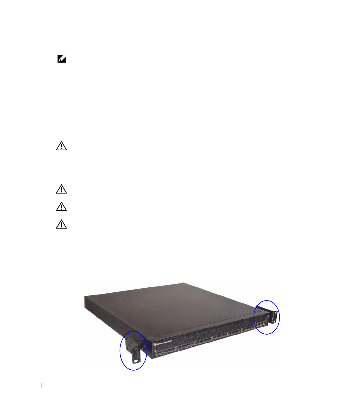
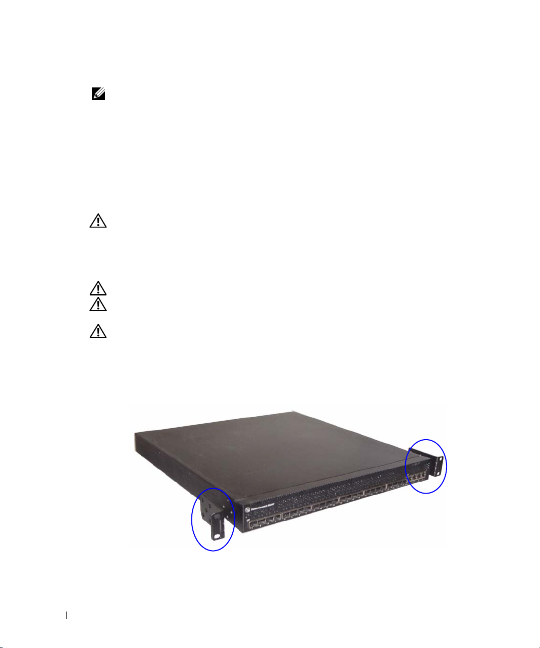
Place the supplied rack-mounting bracket on one side of the switch, ensuring that the
1
mounting holes on the switch line up to the mounting holes in the rack-mounting bracket.
Figure 1 illustrates where to mount the brackets.
Figure 1. Attaching the Brackets
6 Getting Started Guide
Page 9
2
Insert the supplied bolts into the rack-mounting holes and tighten with a screwdriver.
3
Repeat the process for the rack-mounting bracket on the other side of the switch.
4
Insert the switch into the 48.26 cm (19 inch) rack, ensuring that the rack-mounting holes on
the switch line up to the mounting holes in the rack.
5
Secure the switch to the rack with either the rack bolts or cage nuts and cage nut bolts with
washers (depending on the kind of rack you have). Fasten the bolts on bottom before
fastening the bolts on top.
NOTICE: Make sure that the ventilation holes are not obstructed.
CAUTION: Make sure that the supplied rack bolts fit the pre-threaded holes in the rack.
Installing as a Free-standing Switch
NOTICE: We strongly recommend mounting the switch in a rack.
Install the switch on a flat surface if you are not installing it in a rack. The surface must be able
to support the weight of the switch and the switch cables. The switch is supplied with four
self-adhesive rubber pads.
1
Attach the self-adhesive rubber pads on each location marked on the bottom of the switch.
2
Set the switch on a flat surface, and make sure that it has proper ventilation by leaving 5 cm
(2 inches) on each side and 13 cm (5 inches) at the back.
Connecting a Switch to a Terminal
1
Connect the DB9 connector of the RJ-45-to-DB9 serial cable to a VT100 terminal or to a
computer running VT100 terminal emulation software.
2
Connect the RJ-45 connector at the other end to the top RJ-45 port on the rear panel of the
switch. For more information about the location of the console port, see Figure 3.
Getting Started Guide 7
Page 10
Connecting a Switch to a Power Supply
CAUTION: Read the safety information in the Product Information Guide as well as the safety
information for other switches that connect to or support the switch.
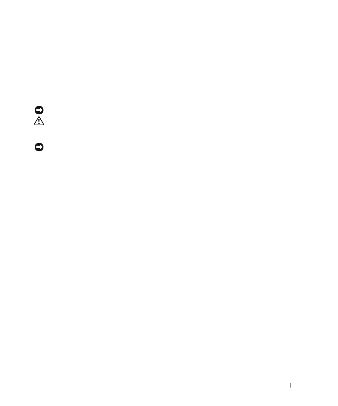
The PowerConnect 8024 and 8024F switches have two power supplies for redundant or loadsharing operation. Each power supply can support 300W.
two power receptacles on the rear panel.
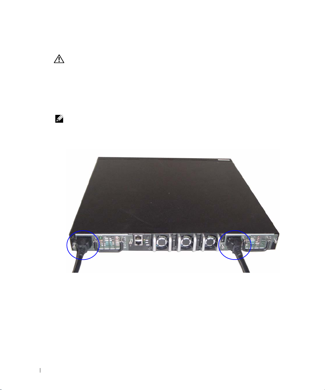
1
Connect one of the supplied AC power cables to one of the AC power connectors located on
the rear panel.
2
To provide a redundant source of power, connect the second supplied AC power cable to the
other AC power connector located on the rear panel.
www.dell.com | support.dell.com
NOTE: Do not connect the power cable to a grounded AC outlet at this time. Connect the switch to a
power source as described in the step detailed in "Starting and Configuring the Switch".
Figure 2. Connecting Power Cables
Figure 2 illustrates the location of the
8 Getting Started Guide
Page 11

Starting and Configuring the Switch
After completing all external connections, connect a terminal to a switch to configure the switch.
Additional advanced functions are described in the
User Documentation
NOTE: Read the release notes for this product before proceeding. You can download the release notes
from the Dell Support website at support.dell.com.
NOTE: We recommend that you obtain the most recent version of the user documentation from the Dell
Support website at support.dell.com.
CD.
User's Guide
Connecting the Terminal to the Switch
To monitor and configure the switch via serial console, use the console port on the rear of the
switch to connect it to a VT100 terminal or to a computer running VT100 terminal emulation
software. The console port is implemented as a data terminal equipment (DTE) connector.
The following is required to use the console port:
• VT100-compatible terminal or a desktop or a portable system with a serial port, running
VT100 terminal emulation software.
• A serial cable (provided) with a RJ-45 connector for the console port and DB9 connector for
the terminal.
Perform the following tasks to connect a terminal to the switch console port:
1
Connect the DB9 connector on the serial cable to the terminal running VT100 terminal emulation
software.
2
Configure the terminal emulation software as follows:
a
Select the appropriate serial port (serial port 1 or serial port 2) to connect to the console.
b
Set the data rate to 9600 baud.
c
Set the data format to 8 data bits, 1 stop bit, and no parity.
d
Set the flow control to none.
e
Set the terminal emulation mode to
f
Select Terminal keys for Function, Arrow, and Ctrl keys. Make sure that the setting is for
Terminal keys (not Microsoft
®
VT100
.
Windows® keys).
located on your
NOTE: When using HyperTerminal with Microsoft Windows 2000, make sure that you have Windows
2000 Service Pack 2 or later installed. With Windows 2000 Service Pack 2, the arrow keys function
properly in HyperTerminal's VT100 emulation. Go to www.microsoft.com for more information on
Windows 2000 service packs.
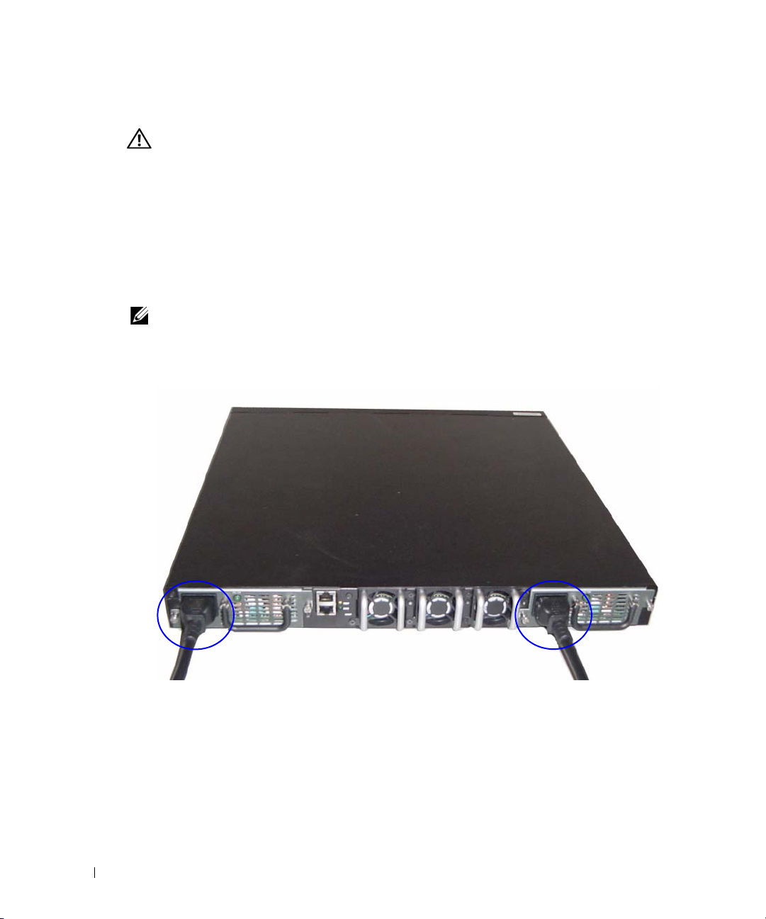
Connect the RJ-45 connector on the cable directly to the switch console port. The
3
PowerConnect 8024 and 8024F console port is located on the rear panel, above the RJ-45
out-of-band port, as shown in Figure 3.
Getting Started Guide 9
Page 12
Figure 3. Connecting to the Console Port
The RJ-45 port below the Console port is for out-of-band management.
www.dell.com | support.dell.com
Booting the Switch
1
Make sure that the switch console port is connected to a VT100 terminal or VT100 terminal
emulator via the RJ-45 to DB9 female cable.
2
Locate two AC power receptacles.
3
Deactivate the AC power receptacle.
4
Connect both of the switch power supplies to the AC receptacles.
5
Activate the AC power receptacles.
When the power is turned on with the local terminal already connected, the switch goes through a
power-on self-test (POST). POST runs every time the switch is initialized and checks hardware
components to determine if the switch is fully operational before completely booting. If POST
detects a critical problem, the program flow stops. If POST passes successfully, valid firmware is
loaded into RAM. POST messages are displayed on the terminal and indicate test success or failure.
The boot process runs for approximately 60 seconds.
Console Port
Initial Configuration
NOTE: The initial simple configuration procedure is based on the following assumptions:
• The PowerConnect switch was never configured before and is in the same state as when you
received it.
• The PowerConnect switch booted successfully.
• The console connection was established and the Dell Easy Setup Wizard prompt appears on
the screen of a VT100 terminal or terminal equivalent.
The initial switch configuration is performed through the console port. After the initial
configuration, you can manage the switch either from the already-connected console port or
remotely through an interface defined during the initial configuration.
NOTE: The switch is not configured with a default user name and password.
NOTE: All of the settings below are necessary to allow the remote management of the switch through
Telnet (Telnet client) or HTTP (Web browser).
10 Getting Started Guide
Page 13

Before setting up the initial configuration of the switch, obtain the following information from
your network administrator:
• The IP address to be assigned to the management VLAN.
• The IP subnet mask for the network.
• The IP address of the management VLAN default gateway.
Management Interface and Out-of-Band Interface
The front panel of the PowerConnect 8024 and 8024F switches contains multiple 10-Gigabit
Ethernet ports for data traffic. Additionally, you can use any port on the front panel as the
in-band management interface. The rear panel contains a Gigabit Ethernet port for out-of-band
(OOB) management. The OOB port is located below the console port.
The Dell Easy Setup Wizard configures network information for the in-band management
interface. To use the OOB interface for management, use the Command Line Interface (CLI)
to configure network information. You can assign a static IP address and subnet mask or enable
DHCP and allow a DHCP server to assign the information automatically.
NOTE: DHCP can be enabled on either the management interface or the OOB interface, but not both.
DHCP is enabled by default on the management interface. To use DHCP on the OOB interface, you must
first disable it on the management interface and then enable it on the OOB interface.
See the PowerConnect 8024 and 8024F CLI Reference Guide for information about the
commands to use to configure the OOB interface.
Initial Configuration Procedure
You can perform the initial configuration using the Dell Easy Setup Wizard, or by using the
Command Line Interface (CLI). The Setup Wizard automatically starts when the switch
configuration file is empty. You can exit the wizard at any point by entering [ctrl+z], but all
configuration settings specified will be discarded (the switch will use the default values).
NOTE: If you do not run the Easy Setup Wizard or do not respond to the initial Easy Setup Wizard prompt
within 60 seconds, the switch enters CLI mode. If the switch is connected to your network through the
management interface when you power it on for the first time, it attempts to acquire an IP address from a
DHCP server. If no DHCP server responds to the request within 50 seconds, the switch uses 192.168.2.1 as
the default IP address on the management VLAN. To view the management interface IP address, enter
enable command to enter Privileged EXEC mode, and then enter show ip interface
the
management
. There is no default IP address for the OOB interface.
Getting Started Guide 11
Page 14

For more information on CLI initial configuration see the
shows how to use the Setup Wizard for initial switch configuration. The wizard sets up the following
configuration on the switch:
• Establishes the initial privileged user account with a valid password. The wizard configures
one privileged user account during the setup.
• Enables CLI login and HTTP access to use the local authentication setting only.
• Sets up the IP address for the management VLAN.
• Sets up the SNMP community string to be used by the SNMP manager at a given IP address.
You may choose to skip this step if SNMP management is not used for this switch.
• Allows you to specify the management server IP or permit management access from all IP
www.dell.com | support.dell.com
addresses.
• Configures the default gateway IP address.
Example Session
This section describes an Easy Setup Wizard session. The following values are used by the example
session:
• The SNMP community string to be used is
• The network management system IP address is
• The user name is
• The IP address for the management VLAN is
• The default gateway is
The setup wizard configures the initial values as defined above. After you complete the wizard, the
switch is configured as follows:
• SNMPv1/2c is enabled and the community string is set up as defined above. SNMPv3 is
disabled by default.
• The admin user account is set up as defined.
• A network management system is configured. From this management station, you can access
the SNMP, HTTP, and CLI interfaces. You may also choose to allow all IP addresses to access
these management interfaces by choosing the (0.0.0.0) IP address.
• An IP address is configured for the default management VLAN (1).
• A default gateway address is configured.
admin
, and password is
0.0.0.0
User Guide
. This
Getting Started Guide
public
192.168.2.1
admin123
.
192.168.2.1:255.255.255.0
.
.
.
NOTE: In the example below, the possible user options are enclosed in [ ]. Also, where possible, the
default value is provided in { }. If you press <Enter> with no options defined, the default value is accepted.
Help text is in parentheses.
12 Getting Started Guide
Page 15

The following example contains the sequence of prompts and responses associated with running an
example Dell Easy Setup Wizard session, using the input values listed above.
After the switch completes the POST and is booted, the following dialog appears:
Unit 1 - Waiting to select management unit)>
Applying configuration, please wait ...
Welcome to Dell Easy Setup Wizard
The Setup Wizard guides you through the initial switch
configuration, and gets you up and running as quickly as possible.
You can skip the setup wizard, and enter CLI mode to manually
configure the switch. You must respond to the next question to run
the setup wizard within 60 seconds, otherwise the system will
continue with normal operation using the default system
configuration.Note: You can exit the setup wizard at any point by
entering [ctrl+z].
Would you like to run the setup wizard (you must answer this
question within 60 seconds)? [Y/N] y
Step 1:
The system is not setup for SNMP management by default. To manage
the switch using SNMP (required for Dell Network Manager) you can
. Set up the initial SNMP version 2 account now.
. Return later and setup other SNMP accounts. (For more
information on setting up an SNMP version 1 or 3 account, see
the user documentation).
Would you like to setup the SNMP management interface now? [Y/N] y
To setup the SNMP management account you must specify the
management system IP address and the "community string" or
password that the particular management system uses to access the
switch. The wizard automatically assigns the highest access level
[Privilege Level 15] to this account. You can use Dell Network
Manager or other management interfaces to change this setting and
to add additional management systems later. For more information
on adding management systems, see the User’s Guide.
Getting Started Guide 13
Page 16

To add a management station:
Please enter the SNMP community string to be used [public]:public
NOTE: If it is configured, the default access level is set to the highest available access for the SNMP
management interface. Initially only SNMPv1/2c will be activated. SNMPv3 is disabled until you return to
configure security access for SNMPv3 (e.g. engine ID, view, etc.).
Please enter the IP address of the Management System (A.B.C.D) or
wildcard (0.0.0.0) to manage from any Management Station
{0.0.0.0}: 192.168.2.100
Step 2:
Now we need to setup your initial privilege (Level 15) user
www.dell.com | support.dell.com
account. This account is used to login to the CLI and Web
interface. You may setup other accounts and change privilege
levels later. For more information on setting up user accounts and
changing privilege levels, see the user documentation.
To setup a user account:
Please enter the user name. [admin]:admin
Please enter the user password:********
Please reenter the user password:********
Step 3:
Next, an IP address is setup. The IP address is defined on the
default VLAN (VLAN #1), of which all ports are members. This is the
IP address you use to access the CLI, Web interface, or SNMP
interface for the switch. Optionally you may request that the
system automatically retrieve an IP address from the network via
DHCP (this requires that you have a DHCP server running on the
network).
To setup an IP address:
Please enter the IP address of the device (A.B.C.D) or enter "DHCP"
(without the quotes) to automatically request an IP address from
the network DHCP server. [192.168.2.1]:192.168.2.1
Please enter the IP subnet mask (A.B.C.D or /nn).
[255.255.255.0]:255.255.255.0
14 Getting Started Guide
Page 17

Step 4:
Finally, setup the default gateway. Please enter the IP address of
the gateway from which this network is reachable. [0.0.0.0]:
This is the configuration information that has been collected:
SNMP Interface = "public"@192.168.2.100
User Account setup = admin
Password = ********
Management IP address = 192.168.2.1 255.255.255.0
Default Gateway = 0.0.0.0
Operation Mode = Normal
Step 5:
If the information is correct, please select (Y) to save the
configuration, and copy to the start-up configuration file. If the
information is incorrect, select (N) to discard configuration and
restart the wizard: [Y/N] y
Thank you for using Dell Easy Set up Wizard. You will now enter CLI
mode.
Advanced Configuration
This section provides summary information about such common tasks as:
• Retrieving an IP Address From a DHCP Server
• Security Management and Password Configuration
NOTE: For detailed information on all the CLI commands available for the 8024 and 8024F M6348
switches, see the CLI Reference Guide.
Retrieving an IP Address From a DHCP Server
When using the DHCP protocol to retrieve an IP address, the switch acts as a DHCP client.
To retrieve an IP address from a DHCP server, perform the following steps:
1
Select and connect any port to a DHCP server or to a subnet that has a DHCP server on it, in
order to retrieve the IP address.
NOTE: You do not need to delete the switch configuration to retrieve an IP address for the D HCP server.
Enter the following commands to use the selected port for receiving the IP address.
2
console#config
console(config)#ip address dhcp
The interface receives the IP address automatically.
Getting Started Guide 15
Page 18

3
To verify the IP address, enter the show ip interface command at the system prompt as shown
in the following example.
console#show ip interface
Management Interface:
IP Address....................................... 10.240.4.125
Subnet Mask..................................... 255.255.255.0
Default Gateway.................................... 10.240.4.1
Burned In MAC Address........................00:10:18:82:04:35
www.dell.com | support.dell.com
Network Configuration Protocol Current................... DHCP
Management VLAN ID.......................................... 1
Routing Interfaces:
Interface IP Address IP Mask Bcast CastFwd
---------- --------------- --------------- -------- --------
vlan1 192.168.10.10 255.255.255.0 Disable Disable
vlan2 0.0.0.0 0.0.0.0 Enable Disable
loopback2 0.0.0.0 0.0.0.0 Disable Disable
Security Management and Password Configuration
System security is handled through the AAA (Authentication, Authorization, and Accounting)
mechanism that manages user access rights, privileges, and management methods. AAA uses both
local and remote user databases. Data encryption is handled through the SSH mechanism.
The system is delivered with no default password configured; all passwords are user-defined. If a
user-defined password is lost, a password recovery procedure can be invoked from the Boot menu.
The procedure is applicable for the local terminal only and allows a one-time access to the switch
from the local terminal with no password entered.
Netdir Multi
16 Getting Started Guide
Page 19

Configuring Security Passwords
The security passwords can be configured for the following services:
• Console
• Telnet
• SSH
•HTTP
•HTTPS
NOTE: When creating a user name, the default priority is "1", which allows access but not configuration
rights. A priority of "15" must be set to enable access and configuration rights to the switch.
Configuring an Initial Console Password
To configure an initial console password, enter the following commands:
console(config)#aaa authentication login default line
console(config)#aaa authentication enable default line
console(config)#line console
console(config-line)#login authentication default
console(config-line)#enable authentication default
console(config-line)#password secret123
• When initially logging on to a switch through a console session, enter
password prompt.
• When changing a switch’s mode to enable, enter
Configuring an Initial Telnet Password
secret123
at the password prompt.
To configure an initial Telnet password, enter the following commands:
console(config)#aaa authentication login default line
console(config)#aaa authentication enable default line
console(config)#line telnet
console(config-line)#login authentication default
console(config-line)#enable authentication default
console(config-line)#password pass1234
• When initially logging onto a switch through a Telnet session, enter
password prompt.
• When changing a switch mode to enable, enter
pass1234
.
secret123
pass1234
Getting Started Guide 17
at the
at the
Page 20

Configuring an Initial HTTP Password
To configure an initial HTTP password, enter the following commands:
console(config)#ip http authentication local
console(config)#username admin password user1234 level 15
Configuring an Initial HTTPS Password
To configure an initial HTTPS password, enter the following commands:
console(config)#ip https authentication local
NOTE: You should generate a new crypto certificate each time you upgrade (install a new version of)
www.dell.com | support.dell.com
the control software application on the switch.
Enter the following commands once when configuring to use an HTTPS session over a console,
a Telnet, or an SSH session.
NOTE: In the Web browser enable SSL 2.0 or greater for the page content to appear.
console(config)#crypto certificate 1 generate
console(config)#ip https server
NOTE: Http and Https services require level 15 access and connect directly to the configuration level
access.
18 Getting Started Guide
Page 21

Managing the Switch
You can manage the switch by using the Web-based interface, command-line interface (CLI),
or SNMP. To manage the switch by using a Web browser or SNMP, the switch must have an IP
address, and it must be accessible from the management station. To manage the switch by using
the CLI, you can use a direct console connection or a remote Telnet/SSH connection.
To establish a direct console connection to the CLI, see "Connecting the Terminal to the Switch"
on page 9. You can use the Easy Setup Wizard To perform the initial configuration that allows
remote management access (see "Initial Configuration Procedure" on page 11). For instructions on
configuring remote management using the CLI, refer to the
Using a Web Browser to Manage the Switch
Starting the Application
1
Open a web browser.
2
Enter the switch’s IP address (as defined in the CLI) in the address bar and press <Enter>.
For information about assigning an IP address to a switch, see "Initial Configuration" on
page 10.
3
When the Login window displays, enter a user name and password.
NOTE: The switch is not configured with a default password, and you can configure the switch without
entering a password when you connect to the CLI by using the console port. Passwords are both case
sensitive and alpha-numeric. For information about recovering a lost password, see the User’s Guide.
Click OK.
4
5
The
Dell OpenManage Switch Administrator
home page displays.
User’s Guide
.
Understanding the Interface
The home page contains the following views:
• Tree view — Located on the left side of the home page, the tree view provides an expandable
view of features and their components.
• Device view — Located on the right side of the home page, the device view is used to display
such things as a view of the device, an information or table area, and/or configuration
instructions.
Getting Started Guide 19
Page 22

www.dell.com | support.dell.com
20 Getting Started Guide
Page 23

Dell™ PowerConnect™
8024 和 8024F 交换机
使用入门指南
型号
PC8024 和 PC8024F
www.dell.com | support.dell.com
Page 24

注、注意和警告
注:“注”表示可以帮助您更好地使用计算机的重要信息。
注意:“注意”表示可能会损坏硬件或导致数据丢失,并告诉您如何避免此类问题。
警告:“警告”表示可能会导致财产损失、人身伤害甚至死亡。
____________________
本说明文件中的信息如有更改,恕不另行通知。
© 2009 Dell Inc.
未经
Dell Inc.
本文中使用的商标:
商标。
本说明文件中述及的其它商标和产品名称是指拥有相应商标和产品名称的公司或其制造的产品。
名称之外的其它商标和产品名称不拥有任何专有权。
型号
PC8024 和 PC8024F
2009 年 11
版权所有,翻印必究。
书面许可,不得以任何方式进行复制。
Dell、DELL
月
P/N X472K Rev. A02
徽标和
PowerConnect 是 Dell Inc.
的商标;
Microsoft 和 Windows 是 Microsoft Corporation
Dell Inc.
的注册
对本公司的商标和产品
Page 25

目录
安装
现场准备 . . . . . . . . . . . . . . . . . . . . . . . . . . . . . . . . .
打开交换机包装
包装箱物品
打开包装步骤
安装交换机
在机架中安装
安装为自立式交换机
将交换机连接至终端
将交换机连接至电源设备
. . . . . . . . . . . . . . . . . . . . . . . . . . . . .
. . . . . . . . . . . . . . . . . . . . . . . . . . . . . 25
. . . . . . . . . . . . . . . . . . . . . . . . . . . . 26
. . . . . . . . . . . . . . . . . . . . . . . . . . . . . . . .
. . . . . . . . . . . . . . . . . . . . . . . . . . . . 26
. . . . . . . . . . . . . . . . . . . . . . . . 27
. . . . . . . . . . . . . . . . . . . . . . . . . . .
. . . . . . . . . . . . . . . . . . . . . . . .
启动和配置交换机
将终端连接至交换机 . . . . . . . . . . . . . . . . . . . . . . . . . . .
引导交换机
初始配置
高级配置
. . . . . . . . . . . . . . . . . . . . . . . . . . . . . . . .
. . . . . . . . . . . . . . . . . . . . . . . . . . . . . . . . .
管理接口和带外接口
初始配置过程
示例会话
. . . . . . . . . . . . . . . . . . . . . . . . . . . . . . . 32
. . . . . . . . . . . . . . . . . . . . . . . . . . . . . . . . .
从 DHCP 服务器检索 IP 地址
安全保护管理和密码配置
. . . . . . . . . . . . . . . . . . . . . . . . 31
. . . . . . . . . . . . . . . . . . . . . . . . . . . . 31
. . . . . . . . . . . . . . . . . . . . . 35
. . . . . . . . . . . . . . . . . . . . . . 37
25
25
26
27
28
29
30
30
35
管理交换机
使用
Web
启动应用程序
了解接口
浏览器管理交换机 . . . . . . . . . . . . . . . . . . . . . . .
. . . . . . . . . . . . . . . . . . . . . . . . . . . . 39
. . . . . . . . . . . . . . . . . . . . . . . . . . . . . . . 39
39
23
Page 26

24
Page 27

安装
本说明文件介绍有关安装、配置和操作
信息。 有关详情,请参阅
站
support.dell.com
User Documentation CD
以获取有关说明文件及固件的最新更新信息。
Dell™ PowerConnect™ 8024 和 8024F
上的《用户指南》,或访问
现场准备
PowerConnect 8024 和 8024F
也可以自立式摆放(放在平坦的平面上),作为独立的交换机使用。
在安装一台或多台交换机之前,请确保选定的安装位置符合以下现场要求:
•
电源
交换机应靠近易于插拔的电源插座(
-
空间要求
•
接和通风的空间。
布线要求
•
明装置)。
•
周围环境
(非冷凝)。
正面及背面有足够的空间,以便操作员进行操作。 请留出用于布线、电源连
-
布线应远离电子噪声源(如无线电发射器、广播放大器、电源线路和荧光照
-
交换机运行环境温度范围为
-
交换机既可安装在标准的
100-250 VAC,50-60 Hz
0 到 45oC(32 到 113oF
48.26
厘米(
英寸)机架中,
19
)进行安装。
),相对湿度最大为
打开交换机包装
包装箱物品
打开每台交换机的包装时,请确保其中包含以下物品:
•
一台
PowerConnect
•
两根交流电源线
•
一根
RJ-45 至 DB9
•
一套用于机架安装的机架固定套件(两个固定支架、螺栓和锁紧螺帽)
•
一套用于自立式交换机的自粘胶垫(包括四个垫)
•
User Documentation
•
使用入门指南
•
产品信息指南
交换机
内孔电缆
CD
系统的基本
支持网
Dell
95%
使用入门指南 25
Page 28
打开包装步骤
注:在打开交换机的包装之前,先检查包装盒,如有任何损坏迹象,请立即报告。
1
将包装盒放在整洁的平坦表面上,然后剪断固定包装盒的所有包装带。
2
打开包装盒或取下包装盒盖。
3
从包装盒中小心取出交换机,然后将其放在稳定且整洁的表面上。
4
取出所有包装材料。
5
检查产品及附件是否出现损坏。
安装交换机
www.dell.com | support.dell.com
警告:请阅读《产品信息指南》中的安全信息,以及连接到该交换机或支持该交换机的其它交
换机的安全信息。
两个交流电源连接器均位于交换机的背面板上。
在机架中安装
警告:请勿使用机架固定套件将交换机悬挂在台面或桌面下,或固定在墙壁上。
警告:断开交换机上的所有电缆,然后继续安装。
(如果已粘连)。
警告:在将多台交换机安装到机架中时,请自底向上安装交换机。
1
将附带的机架固定支架放在交换机的一侧,确保交换机上的固定孔与机架固定支架上的
固定孔对齐。图
显示了支架的安装位置。
1
取出交换机底部的所有自粘垫
图
固定支架
1.
26 使用入门指南
Page 29

2
将附带的螺栓插入机架固定孔,然后用螺丝刀将其拧紧。
3
在交换机的另一侧对机架固定支架重复此过程。
4
将交换机插入
固定孔。
5
使用机架螺栓或锁紧螺帽以及带垫片的锁紧螺帽螺栓(取决于所使用的机架类型),
将交换机固定在机架上。
注意:确保不要堵塞通风孔。
警告:确保附带的机架螺栓插入到机架中的预制螺纹孔中。
48.26
厘米(
英寸)机架,确保交换机上的机架固定孔对准机架上的
19
先在底部拧紧螺栓,然后在顶部固定螺栓。
安装为自立式交换机
注意:强烈建议您在机架中安装交换机。
如果不将交换机安装在机架中,请将其安装在平坦的表面上。 该表面必须能够承受交换机
以及交换机电缆的重量。 交换机附带四个自粘胶垫。
1
在交换机底部的每个标记的位置上贴上自粘胶垫。
2
将交换机放在平坦的表面上,在两侧各留出
(
英寸)的空间,以确保通风良好。
5
厘米(2 英寸)的空间,背面留出
5
13
厘米
将交换机连接至终端
1
将
RJ-45 至 DB9
端仿真软件的计算机。
2
将另一端的
置的详情,请参阅图
串行电缆的
连接器连接至交换机背面板上的顶部
RJ-45
。
3
连接器连接至
DB9
VT100
终端,或者连接至运行
端口。 有关控制台端口位
RJ-45
VT100
终
使用入门指南 27
Page 30
将交换机连接至电源设备
警告:请阅读《产品信息指南》中的安全信息,以及连接到该交换机或支持该交换机的其它交
换机的安全信息。
PowerConnect 8024 和 8024F
设备可以支持
1
将附带的其中一根交流电源线连接至位于背面板上的其中一个交流电源连接器。
2
要提供冗余的电源,请将附带的第二根交流电源线连接至位于背面板上的另一个交流电
源连接器。
注:请勿在此时将电源电缆连接至接地的交流电源插座。 按照“启动和配置交换机”中详细说
www.dell.com | support.dell.com
明的步骤将交换机连接至电源设备。
图
连接电源电缆
2.
300W
交换机有两个电源设备用于冗余或负载共享操作。 每个电源
。
图2 所示为背面板上两个电源插座的位置。
28 使用入门指南
Page 31

启动和配置交换机
完成所有外部连接后,将某个终端与交换机相连,以配置交换机。
上的《用户指南》中介绍了其它高级功能。
注:在继续操作之前,请阅读本产品的版本注释。可以从 Dell 支持网站 support.dell.com 下载版
本注释。
注:我们建议您从 Dell 支持网站 support.dell.com 获取最新版本的用户说明文件。
User Documentation CD
将终端连接至交换机
要通过串行控制台监测和配置交换机,请使用交换机背面的控制台端口,将交换机连接至
VT100
(DTE)
要使用控制台端口,需要以下各项:
要将终端连接至交换机控制台端口,请执行以下任务:
终端或正在运行
连接器。
•
•
1
2
注:在 Microsoft Windows 2000 中使用超级终端时,请确保已安装 Windows 2000 Service Pack 2
3
兼容终端,或者一台配备串行端口并运行
VT100
系统。
一根串行电缆(附带),带有连接控制台端口的
连接器。
将串行电缆上的
按照以下步骤配置终端仿真软件:
a
选择适当的串行端口(串行端口
b
将数据速率设置为
c
将数据格式设置为
d
将流控制设置为
e
将终端仿真模式设置为
f
选择终端键作为功能键、箭头键和
Microsoft
或更高版本。使用 Windows 2000 Service Pack 2 可以确保箭头键在超级终端的 VT100 仿真中正常
工作。有关 Windows 2000 Service Pack 的详情,请访问 www.microsoft.com。
将 电缆上的
控制台端口位于背面板,
8024F
VT100
DB9
®
Windows®
连接器直接连接至交换机的 控制台端口。
RJ-45
终端仿真软件的计算机。控制台端口可用作数据终端设备
VT100
RJ-45
连接器连接至运行
波特。
9600
个数据位、1 个停止位以及无奇偶校验。
8
(无)。
none
VT100
键)。
RJ-45
VT100
或串行端口 2)以连接至控制台。
1
。
Ctrl 键。
带外端口之上,如图3 中所示。
终端仿真软件的终端。
确保此设置适用于终端键(而不是
终端仿真软件的台式机或便携式
连接器和连接终端的
PowerConnect 8024 和
DB9
使用入门指南 29
Page 32

图
连接至控制台端口
3.
控制台端口
www.dell.com | support.dell.com
控制台端口下面的
引导交换机
1
确保通过
仿真器。
2
找到两个交流电源插座。
3
停用交流电源插座。
4
将交换机的两个电源设备连接至交流电源插座。
5
启用交流电源插座。
在已连接本地终端的情况下打开电源时,交换机将进行开机自测
初始化交换机时进行,用于检查硬件组件,以确定交换机在完全引导之前是否完全正常
运转。 如果
POST
效的固件载入到
大约运行
60
初始配置
注:初始简单配置步骤基于以下假设条件:
PowerConnect 交换机此前从未进行过任何配置,其状态与收到时相同。
•
PowerConnect 交换机引导成功。
•
控制台连接已建立,并且 Dell 简易安装向导提示信息显示在 VT100 终端或同等终端设备的屏
•
幕上。
应通过控制台端口执行初始交换机配置。完成初始配置后,既可以通过已连接的控制台端
口管理交换机,也可以通过在初始配置过程中定义的接口对交换机进行远程管理。
注:交换机未配置默认的用户名和密码。
注:要通过 Telnet(Telnet 客户端)或 HTTP(Web 浏览器)来远程管理交换机,需要以下所有
设置。
端口用于带外管理。
RJ-45
RJ-45 至 DB9
内孔电缆将交换机控制台端口连接至
检测到严重问题,程序流将停止。 如果
RAM
中。
信息显示在终端上,用于指出自测是否成功。 引导过程
POST
秒钟。
VT100
终端或
VT100
终端
(POST)。POST
POST
成功通过,则会将一个有
在每次
30 使用入门指南
Page 33

在设置交换机的初始配置之前,从网络管理员处获得以下信息:
•
要分配到管理
•
网络的
•
管理
IP
VLAN
VLAN 的 IP
子网掩码。
默认网关的
IP
地址。
地址。
管理接口和带外接口
PowerConnect 8024 和 8024F
交换机的前面板包含多个用于数据通信的
端口。 此外,您可以将前面板上的任何端口用作带内管理接口。 背面板包含用于带外
(OOB)
Dell
命令行界面
许
有关用于配置
管理的千兆位以太网端口。
简易安装向导可配置带内管理接口的网络信息。 要使用
配置网络信息。 您可以分配静态
(CLI)
DHCP
服务器自动分配该信息。
注:DHCP 可在管理接口或 OOB 接口上启用,但两者不能同时启用。 默认情况下,管理接口上
启用 DHCP。 要在 OOB 接口上使用 DHCP,您必须首先在管理接口上禁用此功能,然后在 OOB
接口上启用此功能。
接口的命令的信息,请参阅
OOB
Guide(PowerConnect 8024 和 8024F CLI
端口位于控制台端口的下面。
OOB
地址和子网掩码或启用
IP
PowerConnect 8024 and 8024F CLI Reference
参考指南)。
接口进行管理,请使用
OOB
千兆位以太网
10
DHCP
初始配置过程
可以使用
空时,将自动启动该安装向导。可以随时通过输入
设置将被丢弃(交换机将使用默认值)。
注:如果您没有运行简易安装向导或没有在 60 秒内响应初始简易安装向导的提示信息,则交换
机会进入 CLI 模式。 如果交换机通过管理接口连接至您的网络,则交换机初次通电时,会尝试
从 DHCP 服务器获取一个 IP 地址。 如果没有 DHCP 服务器在 50 秒内响应该请求,则交换机使用
192.168.2.1 作为管理 VLAN 上的默认 IP 地址。 要查看管理接口 IP 地址,请输入
进入优先执行模式,然后输入
IP 地址。
有关
CLI
安装向导来进行初始交换机配置。该向导设置交换机的以下配置:
•
建立具有权限的初始用户帐户以及有效的密码。在安装过程中,该向导将配置一个具有
权限的用户帐户。
启用
•
•
设置管理
•
设置
SNMP
•
可以指定管理服务器
•
配置默认网关
简易安装向导或命令行界面
Dell
来进行初始配置。当交换机配置文件为
(CLI)
[ctrl+z]
退出向导,但指定的所有配置
enable 命令以
show ip interface management。 OOB 接口没有默认
初始配置的详情,请参阅《用户指南》。 本《使用入门指南》说明了如何使用该
登录和
CLI
HTTP
VLAN 的 IP
SNMP
管理器在指定
管理,则可以选择跳过这一步。
IP
访问,以便仅使用本地验证设置。
地址。
地址要使用的
IP
SNMP
,或允许从所有
IP
地址中进行管理访问。
IP
地址。
团体字符串。如果该交换机不使用
并允
使用入门指南 31
Page 34

示例会话
本节介绍了一个简易安装向导会话。示例会话将使用以下值:
•
要使用的
•
网络管理系统
•
用户名为
•
管理
VLAN 的 IP
•
默认网关为 0.0.0.0
安装向导根据上述定义的方式配置初始值。向导完成后,按照以下方式配置交换机:
•
启用
SNMPv1/2c
www.dell.com | support.dell.com
用状态。
•
根据定义的方式设置
•
配置网络管理系统。从该管理站,可以访问
(0.0.0.0) IP
•
为默认管理
•
配置默认网关地址。
注:在以下示例中,可能的用户选项包括在 [ ] 中。另外,可能时,{ } 中将提供默认值。如果未
定义选项,按 <Enter> 键将接受默认值。帮助文本在括号中。
以下示例包含与使用上面列出的输入值运行
序列。
交换机完成
POST
Unit 1 - Waiting to select management unit
单元)
)>
Applying configuration, please wait ...
Welcome to Dell Easy Setup Wizard
The Setup Wizard guides you through the initial switch configuration,
and gets you up and running as quickly as possible.You can skip the
setup wizard, and enter CLI mode to manually configure the switch. You
must respond to the next question to run the setup wizard within 60
seconds, otherwise the system will continue with normal operation
using the default system configuration. Note:You can exit the setup
wizard at any point by entering [ctrl+z].
机配置,并尽快使您开机并运行。可以跳过安装向导,进入
您必须在
60
继续正常运行。注:可以随时通过按
Would you like to run the setup wizard (you must answer this
question within 60 seconds)?[Y/N]
答此问题]?
SNMP
admin
团体字符串为
地址为 192.168.2.1
IP
,密码为 admin123
地址为 192.168.2.1:255.255.255.0
public
。
。
。
。
。
,并按上述定义的方式设置团体字符串。默认情况下,
用户帐户。
admin
SNMP、HTTP 及 CLI
地址,还可以选择允许所有
VLAN (1) 配置 IP
地址。
地址访问这些管理接口。
IP
简易安装向导示例会话相关的提示和响应
Dell
SNMPv3
接口。通过选择
处于禁
并引导后,将显示以下对话信息:
(正在应用配置,请稍候
(欢迎使用
(单元
Dell
1 -
正在等待选择管理
简易安装向导)
...
)
(该安装向导将指导您完成初始交换
模式以手动配置交换机。
CLI
秒之内答复下一个问题才能运行安装向导,否则系统将使用默认的系统配置
[ctrl+z]
键退出安装向导。)
(是否要运行安装向导 [必须在
60
秒内回
[Y/N])y
32 使用入门指南
Page 35

步骤 1:
The system is not setup for SNMP management by default. To manage
the switch using SNMP (required for Dell Network Manager) you can
(默认情况下,系统未设置为使用
Network Manager
要求],您可以)
SNMP
管理。要使用
SNMP
管理交换机
[Dell
. Set up the initial SNMP version 2 account now.
版本
2
帐户。)
(立即设置初始
SNMP
. Return later and setup other SNMP accounts. (For more
information on setting up an SNMP version 1 or 3 account,
see the user documentation).
有关设置
[
SNMP 版本 1 或 3
帐户的详情,请参阅用户说明文件]。)
(稍后返回并设置其它
SNMP
帐户。
Would you like to setup the SNMP management interface now? [Y/N]
(是否立即设置
SNMP
管理接口?
[Y/N])y
To setup the SNMP management account you must specify the
management system IP address and the "community string" or
password that the particular management system uses to access the
switch. The wizard automatically assigns the highest access level
[Privilege Level 15] to this account. You can use Dell Network
Manager or other management interfaces to change this setting and
to add additional management systems later. For more information
on adding management systems, see the User?s Guide.
理帐户,必须指定管理系统
IP
地址,以及
“团体字符串”或特定管理系统用于访问交换
机的密码。该向导将自动为此帐户分配最高级别的访问权限 [权限级别
Dell Network Manager
有关添加管理系统的详情,请参阅 《用户指南》。
To add a management station:
或其它管理接口更改这一设置,并且稍后添加其它管理系统。
)
(添加管理站:)
(要设置
。可以使用
15]
Please enter the SNMP community string to be used [public]:
要使用的
SNMP
注:如果已配置,默认访问级别将设置为用于访问 SNMP 管理接口的最高权限级别。 最初将
仅激活 SNMPv1/2c。 将禁用 SNMPv3,直至返回而为 SNMPv3 配置安全访问(例如引擎 ID,
查看等)。
团体字符串
[public])public
SNMP
管
(请输入
Please enter the IP address of the Management System (A.B.C.D) or
wildcard (0.0.0.0) to manage from any Management Station
{0.0.0.0}:
任何管理站
{0.0.0.0}
(请输入管理系统的
进行管理:)
地址
IP
[A.B.C.D]
192.168.2.100
或通配符
[0.0.0.0]
以便从
使用入门指南 33
Page 36

步骤 2:
Now we need to setup your initial privilege (Level 15) user
account. This account is used to login to the CLI and Web
interface. You may setup other accounts and change privilege
levels later. For more information on setting up user accounts and
changing privilege levels, see the user documentation.
置初始权限 [级别
用户帐户。该帐户用于登录到
15]
CLI
接口及
(现在,需要设
Web
接口。稍后,
可以设置其它帐户并更改权限级别。有关设置用户帐户和更改权限级别的详情,请参阅用
户说明文件。)
To setup a user account:
www.dell.com | support.dell.com
Please enter the user name.
Please enter the user password:
Please reenter the user password:
步骤 3:
Next, an IP address is setup. The IP address is defined on the
default VLAN (VLAN #1), of which all ports are members. This is the
IP address you use to access the CLI, Web interface, or SNMP
interface for the switch. Optionally you may request that the
system automatically retrieve an IP address from the network via
DHCP (this requires that you have a DHCP server running on the
network).
其中的所有端口均是成员。对于交换机,这是用于访问
接口的
求有
IP
DHCP
To setup an IP address:
Please enter the IP address of the device (A.B.C.D) or enter "DHCP"
(without the quotes) to automatically request an IP address from
the network DHCP server. [192.168.2.1]:
[A.B.C.D]
[192.168.2.1]
Please enter the IP subnet mask (A.B.C.D or /nn). [255.255.255.0]:
(请输入
IP
255.255.255.0
(设置用户帐户:)
(请输入用户名。)
(请输入用户密码:)
(请重新输入用户密码:)
(接下来,设置
地址。在默认的
IP
地址。另外,您还可以请求系统通过
服务器在网络上运行]。)
或输入
"DHCP" [
:)
子网掩码
(设置
不带引号],自动向网络
192.168.2.1
[A.B.C.D 或 /nn]。[255.255.255.0]
IP
地址:)
[admin]:admin
********
VLAN [VLAN #1]
CLI
DHCP
接口、
从网络自动检索
(请输入设备的
DHCP
服务器请求
上定义
Web
IP
IP
:)
********
IP
接口或
SNMP
地址 [这要
地址
IP
地址,
地址。
34 使用入门指南
Page 37

步骤 4:
Finally, setup the default gateway. Please enter the IP address
of the gateway from which this network is reachable. [0.0.0.0]:
(最后,设置默认网关。请输入通过其可访问网络的网关
IP
地址。
[0.0.0.0]
:)
地址
(以
=
This is the configuration information that has been collected:
下是已收集的配置信息:)
SNMP Interface(SNMP
User Account setup =
Password = ********
Management IP address = 192.168.2.1 255.255.255.0
192.168.2.1 255.255.255.0
Default Gateway = 0.0.0.0
Operation Mode = Normal
步骤5:
If the information is correct, please select (Y) to save the
configuration, and copy to the start-up configuration file. If the
information is incorrect, select (N) to discard configuration and
restart the wizard:[Y/N]
制到启动配置文件。如果信息不正确,请选择
[Y/N]) y
Thank you for using Dell Easy Set up Wizard. You will now enter CLI
mode.
(感谢您使用
Dell
接口)
(用户帐户设置 =)
(密码
= "public"@192.168.2.100
admin
= ********
)
(默认网关
(运行模式
(如果信息正确,请选择
简易安装向导。现在您将进入
)
= 0.0.0.0
正常)
=
[N]
(管理
IP
)
[Y]
丢弃配置,然后重新启动向导:
保存配置,并将其复
模式。)
CLI
高级配置
本节提供有关以下常见任务的摘要信息:
•
从
DHCP
•
安全保护管理和密码配置
注:有关可用于 8024 和 8024F M6348 交换机的所有 CLI 命令的详情,请参阅《CLI 参考指南》。
服务器检索
IP
地址
从
DHCP
使用
要从
1
服务器检索
DHCP
DHCP
选择任何一个端口并将其连接至
IP
注:从 DHCP 服务器检索 IP 地址不需要删除交换机配置。
协议检索
服务器检索
地址。
地址
IP
地址时,该交换机用作
IP
地址,请执行以下步骤:
IP
DHCP
DHCP
服务器或具有
客户端。
DHCP
服务器的子网,以便检索
使用入门指南 35
Page 38

2
输入以下命令,以使用选定的端口来获取
console#config
console(config)#ip address dhcp
IP
地址。
接口将自动获取
3
要验证
IP
console#show ip interface
Management Interface:
IP Address(IP
www.dell.com | support.dell.com
Subnet Mask
Default Gateway
Burned In MAC Address
Network Configuration Protocol Current
Management VLAN ID
Routing Interfaces:
Interface IP Address IP Mask Bcast CastFwd
(接口) (
---------- ------------- -------------- ------------- -------------
vlan1 192.168.10.10 255.255.255.0 Disable
vlan2 0.0.0.0 0.0.0.0 Enable
loopback2 0.0.0.0 0.0.0.0 Disable
地址。
IP
地址,请在系统提示符后输入
(管理接口:)
地址)
(子网掩码)
(默认网关)
............................. 10.240.4.125
........................... 255.255.255.0
.......................... 10.240.4.1
(固化
MAC
(管理
VLAN ID)........................... 1
(路由接口:)
地址) (
IP
IP
掩码)
show ip interface
地址)
.........00:10:18:82:04:35
(当前网络配置协议)
Netdir Multi
命令,如下例中所示。
...DHCP
(禁用)
(启用)
(禁用)
Disable
Disable
Disable
(禁用)
(禁用)
(禁用)
36 使用入门指南
Page 39

安全保护管理和密码配置
系统安全保护是通过
权限、特权和管理方法。
处理的。
系统在出厂时未配置默认密码;所有密码均由用户定义。 如果用户定义的密码丢失,则可
以从
(引导)菜单中调用密码恢复程序。该程序仅适用于本地终端,并允许在不输入
Boot
密码的情况下从本地终端一次性访问交换机。
配置安全保护密码
您可以为以下服务配置安全保护密码:
•
控制台
•
Telnet
•
SSH
•
HTTP
•
HTTPS
注:创建用户名时,默认的优先级为 "1",即允许访问权限但不允许配置权限。必须将优先级设
置为 "15" 才能启用对交换机的访问权限和配置权限。
配置初始控制台密码
要配置初始控制台密码,请输入以下命令:
console(config)#aaa authentication login default line
(验证、授权和计费)机制进行处理的,它可以管理用户访问
AAA
使用本地和远程用户数据库。数据加密是通过
AAA
SSH
机制进行
console(config)#aaa authentication enable default line
console(config)#line console
console(config-line)#login authentication default
console(config-line)#enable authentication default
console(config-line)#password secret123
•
通过控制台会话首次登录交换机时,请在密码提示符后输入 secret123
•
将交换机的模式更改为启用时,请在密码提示符后输入 secret123
。
。
使用入门指南 37
Page 40

配置初始
要配置初始
Teln et
Telnet
console(config)#aaa authentication login default line
console(config)#aaa authentication enable default line
console(config)#line telnet
console(config-line)#login authentication default
console(config-line)#enable authentication default
console(config-line)#password pass1234
•
通过
www.dell.com | support.dell.com
•
Telnet
将交换机的模式更改为启用时,请输入 pass1234
密码
密码,请输入以下命令:
会话首次登录交换机时,请在密码提示符后输入 pass1234
。
。
配置初始
要配置初始
HTTP
HTTP
密码
密码,请输入以下命令:
console(config)#ip http authentication local
console(config)#username admin password user1234 level 15
配置初始
HTTPS
要配置初始
密码
HTTPS
密码,请输入以下命令:
console(config)#ip https authentication local
注:您应在每次升级交换机上的控制软件应用程序(安装新版本)时生成新的 crypto 证书。
配置为通过控制台、
注:在 Web 浏览器中,启用 SSL 2.0 或更高版本以显示页面内容。
Telnet 或 SSH
会话使用
HTTPS
会话时,只需输入一次以下命令。
console(config)#crypto certificate 1 generate
console(config)#ip https server
注:Http 和 Https 服务需要的访问权限级别为 15,并直接连接至配置级别的访问。
38 使用入门指南
Page 41

管理交换机
您可以通过基于
器或
SNMP
过
CLI
要建立到
使用简易安装向导执行初始配置,以允许远程管理访问(请参阅第
过程”)。 有关使用
使用
管理交换机,交换机必须具有
管理交换机,可以使用直接的控制台连接或远程
的直接控制台连接,请参阅第
CLI
Web
的接口、命令行界面
Web
配置远程管理的说明,请参阅《用户指南》。
CLI
(CLI) 或 SNMP
IP
浏览器管理交换机
管理交换机。 要通过
地址,并且必须可从管理站进行访问。 要通
Telnet/SSH
页的“将终端连接至交换机”。 您可以
29
连接。
页的“初始配置
31
启动应用程序
1
打开
2
在地址栏中输入交换机的
有关为交换机分配
3
当显示
注:交换机未配置默认密码,可以在通过控制台端口连接到 CLI 时对交换机进行配置而无需输
入密码。密码区分大小写,并且只能为字母数字。 有关恢复丢失密码的信息,请参阅《用户
指南》。
4
单击
5
系统将显示
浏览器。
Web
Login
(确定)。
OK
地址(如
IP
地址的信息,请参阅第
IP
(登录)窗口时,请输入用户名和密码。
Dell OpenManage Switch Administrator
中所定义)并按
CLI
30
页的“初始配置”。
主页。
<Enter>
键。
了解接口
主页包含以下视图:
•
树视图
•
设备视图
之类的信息。
树视图位于主页左侧,提供了功能及其组件的可展开视图。
-
设备视图位于主页右侧,用于显示设备的视图、信息或表区域和/或配置说明
-
Web
浏览
使用入门指南 39
Page 42

www.dell.com | support.dell.com
40 使用入门指南
Page 43

Dell™ PowerConnect™
8024 與 8024F 交換機
入門指南
機型 PC8024 與 PC8024F
www.dell.com | support.dell.com
Page 44

註,注意,警示
註:「註」指出可協助您善加利用電腦的重要資訊。
注意:「注意」表示可能會損壞硬體或導致資料遺失,並告訴您如何避免此類問題的發生。
警示 : 「警示」表示可能會導致財產損壞、人身受傷或生命危險。
____________________
對本文件中所含資訊之變更恕不另行通知。
© 2009 Dell Inc. 版權所有,翻印必究。
未經 Dell Inc. 之書面許可,不得以任何方式重製。
本文所用商標:Dell、DELL 標誌以及 PowerConnect 是 Dell Inc. 的商標;Microsoft 和 Windows 是 Microsoft Corporation 的註冊
商標。
本文件所述及之其他商標或品牌名稱,均各自分屬其商標或產品名稱之申請者或擁有者所擁有。Dell Inc. 對本公司之外的商標和
產品名稱不擁有任何專有權。
機型 PC8024 與 PC8024F
2009 年 11 月 P/N X472K Rev. A02
Page 45

目錄
安裝
現場準備 . . . . . . . . . . . . . . . . . . . . . . . . . . . . . . . . . 45
拆開交換機包裝
包裝箱物品
拆開包裝的步驟
安裝交換機
安裝機架
安裝為獨立式交換機
將交換機連接至終端
將交換機連接至電源供應器
. . . . . . . . . . . . . . . . . . . . . . . . . . . . . 45
. . . . . . . . . . . . . . . . . . . . . . . . . . . . . 45
. . . . . . . . . . . . . . . . . . . . . . . . . . . 46
. . . . . . . . . . . . . . . . . . . . . . . . . . . . . . . . 46
. . . . . . . . . . . . . . . . . . . . . . . . . . . . . . . 46
. . . . . . . . . . . . . . . . . . . . . . . . 47
. . . . . . . . . . . . . . . . . . . . . . . . . . . 47
. . . . . . . . . . . . . . . . . . . . . . . 48
啟動和設定交換機
將終端連接至交換機 . . . . . . . . . . . . . . . . . . . . . . . . . . . 49
啟動交換機
初始設定
進階設定
. . . . . . . . . . . . . . . . . . . . . . . . . . . . . . . . 50
. . . . . . . . . . . . . . . . . . . . . . . . . . . . . . . . . 50
管理介面及頻外介面
初始設定程序
範例作業階段
. . . . . . . . . . . . . . . . . . . . . . . . . . . . . . . . . 55
從 DHCP 伺服器擷取 IP 位址
安全管理和密碼設定
. . . . . . . . . . . . . . . . . . . . . . . . 51
. . . . . . . . . . . . . . . . . . . . . . . . . . . . 51
. . . . . . . . . . . . . . . . . . . . . . . . . . . . 52
. . . . . . . . . . . . . . . . . . . . . 55
. . . . . . . . . . . . . . . . . . . . . . . . 57
管理交換機
使用 Web 瀏覽器管理交換機 . . . . . . . . . . . . . . . . . . . . . . . 59
啟動應用程式
瞭解介面
. . . . . . . . . . . . . . . . . . . . . . . . . . . . 59
. . . . . . . . . . . . . . . . . . . . . . . . . . . . . . . 59
43
Page 46

44
Page 47

安裝
本文件提供安裝、設定及操作 Dell™ PowerConnect™ 8024 與 8024F 系統的基本資訊。
如需詳細資訊,請參閱 User Documentation CD 上的《使用者指南》,或存取 Dell 支援
網站 support.dell.com 以獲取有關文件及韌體的最新更新。
現場準備
PowerConnect 8024 與 8024F 交換機可安裝於標準的 48.26 公分 (19 吋 ) 機架中,亦可自立
式擺放 ( 置於平坦表面上 ),用作獨立交換機。
在安裝交換機之前,請確保所選的安裝位置符合下列現場要求:
•
電源
-
交換機應靠近
•
空間
-
正面及背面有方便操作員作業的足夠空間。 請留出用於纜線佈置、電源連接及通
風的空間。
•
纜線佈置
熒光照明裝置。
周圍環境
•
(
無凝結)。
-
纜線佈置應遠離電氣噪聲源,例如無線電發射器、廣播放大器、電源線路及
-
交換機作業環境的溫度範圍為
拆開交換機包裝
包裝箱物品
拆開每台交換機的包裝時,請確保其中包含以下物品:
•
一台
PowerConnect
•
兩根
AC
電源線
•
一根
RJ-45 至 DB9
•
一套用於機架安裝的機架安裝套件 (兩個安裝托架、螺栓及鎖緊螺母
•
一套用於自立式擺放交換機的自黏性橡膠墊 (內含四個墊
User Documentation
•
100-250 VAC、50-60 Hz
交換機
的母接頭纜線
CD
電源插座。
0 至 45oC (32 至 113oF)
)
,相對濕度最大為
)
95%
•
入門指南
•
產品資訊指南
入門指南 45
Page 48

拆開包裝的步驟
註:在拆開交換機的包裝之前,先檢查包裝盒,如有任何損壞跡像,請立即報告。
1
將包裝盒放在整潔的平坦表面上,然後剪斷固定包裝盒的所有包裝帶。
2
拆開包裝箱或取下包裝箱蓋。
3
從包裝盒中小心地取出交換機,然後將其放在穩定且整潔的表面上。
4
取出所有包裝材料。
5
檢查產品及附件是否出現損壞。
安裝交換機
www.dell.com | support.dell.com
警示 : 閱讀 《產品資訊指南》中的安全資訊以及連接或支援本交換機的其他交換機之安全
資訊。
交換機背面板上有兩個 AC 電源連接器。
安裝機架
警示 : 切勿使用機架安裝套件將交換機懸掛在桌台下,或者固定至牆面。
警示 : 從交換機上拔下所有纜線,然後繼續。 從交換機底部取出所有自黏性橡膠墊
( 如已黏連 )。
警示 : 在一個機架上安裝多台交換機時,請自下向上安裝交換機。
1
將隨附的機架安裝托架安裝在交換機的一側,確定交換機上的安裝孔與機架安裝托架上
的安裝孔對齊。
圖1-1
顯示了托架的安裝位置。
圖 1-1. 連接托架
46 入門指南
Page 49

2
將隨附的螺栓插入機架安裝孔並用螺絲起子旋緊。
3
重複執行此程序,以在交換機的另一側安裝機架安裝托架。
4
將交換機插入
對齊。
5
用機架螺栓或鎖緊螺母以及帶墊圈的鎖緊螺母螺栓 (視您使用的機架類型而定),將交換
機固定至機架。
注意:確保不要阻塞通風孔。
警示 : 確保隨附的機架螺栓插入機架的預製螺紋孔。
48.26 公分 (19 吋)
先旋緊底部的螺栓,然後旋緊頂部的螺栓。
機架,確定交換機上的機架安裝孔與托架上的安裝孔
安裝為獨立式交換機
注意:我們極力建議您將交換機安裝在機架中。
如果不安裝到機架中,則安裝到平坦的表面。 該表面必須能夠支撐交換機及交換機纜線的
重量。 交換機隨附有四個自黏性橡膠墊-。
1
在交換機底部每個標記的位置黏貼上自黏性橡膠墊。
2
將交換機放在平坦的表面上,在兩側留出
的空間,以確保通風良好。
5
公分
(2 吋)
的空間,背面留出
13 公分 (5吋)
將交換機連接至終端
1將 RJ-45 至 DB9
端模擬軟體的電腦。
2
將另一端的
台連接埠位置的資訊,請參見圖
序列電纜的
RJ-45
連接器連接至交換機背面板上的頂部
DB9
連接器連接至
1-3
。
VT100
終端,或者連接至執行
RJ-45
連接埠。 如需更多關於主控
VT100
終
入門指南 47
Page 50

將交換機連接至電源供應器
警示 : 閱讀 《產品資訊指南》中的安全資訊以及連接或支援本交換機的其他交換機之安全
資訊。
PowerConnect 8024 與 8024F 交換機有兩個電源供應器用於冗餘或負載共用作業。 每個電
源供應器均可支援 300W。
1
將一條提供的
2
為提供冗餘電源,將第二條提供的
註:此時不要將電源線連接至接地的 AC 電源插座。 將交換機連接至電源,詳細步驟請見
「啟動和設定交換機」。
AC
圖
1-2
顯示了背面板上兩個電源插孔的位置。
電源線連接至背面板上的一個
AC
電源線連接至背面板上的另一個
AC
電源連接器。
AC
電源連接器。
www.dell.com | support.dell.com
圖 1-2. 連接電源線
48 入門指南
Page 51

啟動和設定交換機
完成所有外部連接之後 ,,將終端連接至交換機以設定該交換機。User Documentation CD
上的《使用者指南》中介紹了其他進階功能。
註:在繼續操作之前,請閱讀本產品的版本說明。可以從 Dell 支援網站 support.dell.com 下載版
本說明。
註:建議從 Dell 支援網站 support.dell.com 獲取最新版本的使用者文件。
將終端連接至交換機
若要透過序列主控台監控和設定交換機,請使用交換機背面的主控台連接埠,將交換機連
接至 VT100 終端或執行 VT100 終端模擬軟體的電腦。主控台連接埠可用作資料終端裝置
(DTE) 連接器。
若要使用主控台連接埠,需要滿足以下條件:
• VT100
•
執行下列工作以將終端連接至交換機主控台連接埠:
1
2
註:在 Microsoft Windows 2000 中使用超級終端時,請確保已安裝 Windows 2000 Service Pack 2
3將
相容終端,或者一台配備序列埠並執行
式電腦。
一根序列電纜 (附帶),帶有連接控制台埠的
將序列電纜上的
按照以下步驟設定終端模擬軟體:
a
選擇適當的序列埠 (序列埠
b
將資料速率設定為
c
將資料格式設定為
d
將流量控制設定為
e
將終端模擬模式設定為 VT100
f
對於
Terminal keys (
Windows
或更高版本。使用 Windows 2000 Service Pack 2 可以確保箭頭鍵在超級終端的 VT100 模擬中正常
工作。請瀏覽 www.microsoft.com 以獲得 Windows 2000 服務套件的更多資訊。
纜線上的
8024F
主控台連接埠位於,
DB9
連接器與執行
9600
8
個資料位元、1 個停止位元以及無同位檢查。
none (無)
Function, Arrow, and Ctrl keys (
終端機按鍵)。 確保此設定適用於終端機按鍵 (而不是
®
按鍵)。
RJ-45
連接器直接連接至交換機的 主控台連接埠。
RJ-45
VT100
1
或序列埠
鮑。
。
。
頻外連接埠上方,如圖
VT100
RJ-45
終端模擬軟體的終端相連。
2)
以連接至主控台。
功能鍵、方向鍵和
終端模擬軟體的桌上型電腦或便攜
連接器和連接終端的
Ctrl 鍵)
PowerConnect 8024 與
1-3
所示。
DB9
連接器。
選項,請選擇
Microsoft®
入門指南 49
Page 52

圖 1-3. 連接至主控台連接埠
主控台連接埠
www.dell.com | support.dell.com
主控台連接埠下方的 RJ-45 連接埠用於頻外管理。
啟動交換機
1
確保交換機的主控台連接埠已透過
終端模擬器。
2
找到兩個
3
關閉
AC
4
將兩個交換機電源供應器連接至
5
啟動
AC
在已連接本機終端的情況下開啟電源時,交換機將進行開機自我測試 (POST)。 每次初始
化交換機時都會執行 POST,在完全開機前檢查硬體元件以確定交換機是否可完全運作。
如果 POST 偵測到重大問題,程式流將會停止。 如果 POST 成功通過,有效的韌體將會
載入到 RAM。 表示測試成功或失敗的 POST 訊息將顯示在終端上。 開機程序執行時間約
為 60 秒。
初始設定
註:初始的簡單設定步驟基於下列假設條件:
• PowerConnect 交換機此前從未進行過任何設定,其狀態與收到時相同。
• PowerConnect 交換機已成功啟動。
• 主控台連線已建立,並且 Dell 簡易安裝精靈提示資訊顯示在 VT100 終端或對應終端裝置的
螢幕上。
應透過主控台連接埠執行初始交換機設定。完成初始設定後,既可以透過已連接的主控台
連接埠管理交換機,也可以透過在初始設定過程中定義的介面對交換機進行遠端管理。
註:交換機未設定預設的使用者名稱和密碼。
註:若要透過遠端登入 ( 遠端登入用戶端 ) 或 HTTP (Web 瀏覽器 ) 來遠端管理交換機,需要以下
所有設定。
AC
電源插孔。
電源插孔。
電源插孔。
RJ-45 至 DB9
AC
插孔。
母接頭纜線連接至
VT100
終端或
VT100
50 入門指南
Page 53

在設定交換機的初始組態之前,從網路管理員處獲得以下資訊:
•
要指定到管理
•
網路的
•
管理
VLAN
VLAN 的 IP
IP
子網路遮罩。
預設閘道的
IP
位址。
位址。
管理介面及頻外介面
PowerConnect 8024 與 8024F 交換機的前面板包含多個用於傳輸資料流量的 10-Gigabit 乙太
網路連接埠。 此外,您亦可將前面板上的任何連接埠用作頻內管理介面。- 背面板包含一
個 Gigabit 乙太網路連接埠,用於頻外 (OOB) 管理。 OOB 連接埠位於主控台連接埠下方。
Dell 簡易設定精靈用於設定帶內管理介面的網路資訊。 要使用 OOB 介面進行管理,請使
用指令行介面 (CLI) 設定網路資訊。 您可以指定靜態 IP 位址與子網路遮罩,或者啟用
DHCP 並讓 DHCP 伺服器自動指定資訊。
註:DHCP 可在管理介面或 OOB 介面上啟用,但不可同時在兩個介面上啟用。 DHCP 預設在管
理介面上啟用。 要在 OOB 介面上使用 DHCP,您必須先在管理介面上停用它,然後在 OOB 介面
上啟用。
請參閱《PowerConnect 8024 與 8024F CLI 參考指南》,以了解要用於設定 OOB 介面的指
令之資訊。
初始設定程序
可以使用 Dell 簡易設定精靈或指令行介面 (CLI) 來執行初始設定。當交換機設定檔為
空時,將自動啟動該設定精靈。可以隨時透過輸入 [ctrl+z] 結束精靈,但指定的所有組
態設定將被丟棄 ( 交換機將使用預設值 )。
註:如果在 60 秒鐘內不執行簡易設定精靈或不回應初始的簡易設定精靈提示,交換機將進入
CLI 模式。 如果交換機在您第一次開啟電源時是透過管理介面連線至網路,將會嘗試從 DHCP 伺
服器獲取 IP 位址。 如果在 50 秒鐘內沒有 DHCP 伺服器回應要求,交換機將使用 192.168.2.1 作為
管理 VLAN 的預設 IP 位址。 要檢視管理介面的 IP 位址,請輸入
EXEC 模式,然後輸入
show ip interface management。 OOB 介面沒有預設 IP 位址。
如需 CLI 初始設定的詳細資訊,請參閱《使用者指南》。 本《入門指南》說明如何使用該
設定精靈來執行初始的交換機設定。該精靈設定交換機的以下組態:
•
建立具有權限的初始使用者帳戶及有效密碼。在設定過程中,該精靈將設定一個具有權
限的使用者帳戶。
•
啟用
CLI
登入和
•
設定管理
•
設定
SNMP
允許指定管理伺服器
•
•
設定預設閘道
VLAN 的 IP
SNMP
管理,則可以選擇跳過這一步。
HTTP
存取,以便僅使用本地驗證設定。
位址。
管理員要使用的
IP
,或允許從所有
IP
位址。
SNMP
社群字串 (指定了
IP
位址中進行管理存取。
enable 指令以進入 Privileged
IP
位址)。如果交換機不使用
入門指南 51
Page 54

範例作業階段
本節介紹一個簡單的設定精靈作業階段。範例作業階段將使用以下值:
•
要使用的
•
網路管理系統
•
使用者名稱為 admin
•
管理
VLAN 的 IP
•
預設閘道為 0.0.0.0
設定精靈根據上述定義的方式設定初始值。精靈完成後,按照以下方式設定交換機:
•
啟用
SNMPv1/2c
•
www.dell.com | support.dell.com
根據定義設定
•
設定網路管理系統。從該管理站可以存取
(0.0.0.0) IP
•
為預設管理
•
設定預設閘道位址。
註:在以下範例中,可能的使用者選項包括在 [ ] 中。另外,可能時,{ } 中將提供預設值。如果
未定義選項,按 <Enter> 鍵將接受預設值。說明文字在括弧中。
以下示例包含與使用上面列出的輸入值執行 Dell 簡易設定精靈範例作業階段相關的提示序
列和回應。
交換機完成 POST 並啟動後,將顯示以下對話資訊:
Unit 1 - Waiting to select management unit ( 單元 1 – 正在等待選擇管理
單元 )>
SNMP
社群字串為 public
IP
位址為 192.168.2.1
,密碼為 admin123
位址為 192.168.2.1:255.255.255.0
。
,並按上述定義的方式設定社群字串。
admin
使用者帳戶。
位址,還可以選擇允許所有
VLAN (1) 設定 IP
位址。
。
。
。
SNMP、HTTP 及 CLI
IP
位址存取這些管理介面。
。
SNMPv3
預設停用。
介面。透過選擇
Applying configuration, please wait ...( 正在套用組態,請稍候 ...)
Welcome to Dell Easy Setup Wizard ( 歡迎使用 Dell 簡易安裝精靈 )
The Setup Wizard guides you through the initial switch
configuration, and gets you up and running as quickly as possible.
You can skip the setup wizard, and enter CLI mode to manually
configure the switch. You must respond to the next question to run
the setup wizard within 60 seconds, otherwise the system will
continue with normal operation using the default system
configuration.Note: You can exit the setup wizard at any point by
entering [ctrl+z]. ( 設定精靈指導您完成初始的交換機組態,讓您盡快使用交
換機。您可以跳過設定精靈,進入 CLI 模式以手動方式設定交換機。必須回答下一個
問題,在 60 秒內執行設定精靈,否則系統將繼續使用預設的系統組態正常作業。
註:可以隨時透過輸入
Would you like to run the setup wizard (you must answer this
question within 60 seconds)? [Y/N] y ( 要執行安裝精靈 [ 必須在 60 秒內回
答該問題 ] 嗎? [Y/N]) y
52 入門指南
[ctrl+z] 鍵結束設定精靈。)
Page 55

步驟 1:
The system is not setup for SNMP management by default. To manage
the switch using SNMP (required for Dell Network Manager) you can
( 系統預設並未設定用於 SNMP 管理。若要使用 SNMP 管理交換機 (Dell Network
Manager 所必需 ),您可以 )
. Set up the initial SNMP version 2 account now. ( 立即設定初始的
SNMP 版本 2。)
. Return later and setup other SNMP accounts. (For more
information on setting up an SNMP version 1 or 3 account,
see the user documentation). ( 稍後返回並設定其他 SNMP 帳戶。( 如需
設定 SNMP 版本 1 或 3 帳戶的詳細資訊,請參閱使用者文件 ))。
Would you like to setup the SNMP management interface now? [Y/N] n
( 立即設定 SNMP 管理介面嗎? [Y/N]) y
To setup the SNMP management account you must specify the
management system IP address and the "community string" or
password that the particular management system uses to access the
switch. The wizard automatically assigns the highest access level
[Privilege Level 15] to this account. You can use Dell Network
Manager or other management interfaces to change this setting and
to add additional management systems later. For more information
on adding management systems, see the User's Guide. ( 要設定 SNMP 管
理帳戶
,您必須指定管理系統 IP 位址,以及 「社群字串」或特定管理系統用於存取交換
機的密碼。該精靈將自動為此帳戶指定最高存取級別 [ 特殊權限級別 15]。您可以使用
Dell Network Manager 或其他管理介面變更此設定,並在稍後新增其他管理系統。
如需新增管理系統的詳細資訊,請參閱 《使用者指南》 )。
To add a management station:( 若要新增管理站:)
Please enter the SNMP community string to be used [public]:( 請輸入
要使用的 SNMP 社群字串 [public])public
註:如已設定,預設存取級別將設定為用於存取 SNMP 管理介面之最高級別。 最初僅啟動
SNMPv1/2c。 SNMPv3 將停用至您返回為 SNMPv3 設定安全存取 ( 如引擎 ID、檢視等 ) 為止。
Please enter the IP address of the Management System (A.B.C.D) or
wildcard (0.0.0.0) to manage from any Management Station
{0.0.0.0}: ( 請輸入管理系統的 IP 位址 (A.B.C.D) 或萬用字元 (0.0.0.0) 以
從任何管理站 {0.0.0.0} 進行管理:) 192.168.2.100
入門指南 53
Page 56

步驟 2:
Now we need to setup your initial privilege (Level 15) user
account. This account is used to login to the CLI and Web
interface. You may setup other accounts and change privilege
levels later. For more information on setting up user accounts and
changing privilege levels, see the user documentation. ( 現在需要設定
初始權限 (15 級 ) 使用者帳戶。此帳戶用於登入 CLI 及 Web 介面。您稍後可以設定
其他帳戶和變更權限。如需設定使用者帳戶及變更權限的詳細資訊,請參閱使用者文件 )。
To setup a user account: ( 若要設定使用者帳戶:)
Please enter the user name. ( 請輸入使用者名稱。) [admin]:admin
www.dell.com | support.dell.com
Please enter the user password: ( 請輸入使用者密碼:)********
Please reenter the user password: ( 請重新輸入使用者密碼:)********
步驟 3:
Next, an IP address is setup. The IP address is defined on the
default VLAN (VLAN #1), of which all ports are members. This is the
IP address you use to access the CLI, Web interface, or SNMP
interface for the switch. Optionally you may request that the
system automatically retrieve an IP address from the network via
DHCP (this requires that you have a DHCP server running on the
network). ( 接下來設定 IP
所有連接埠均為此 VLAN 的成員。此 IP 位址用於存取交換機的 CLI、Web 介面或
SNMP 介面。您可以請求系統透過 DHCP 自動從網路擷取 IP 位址 [ 必須有 DHCP 伺服
器在網路上執行 ])。
位址。IP 位址在預設的 VLAN (VLAN #1) 上設定,
To setup an IP address: ( 若要設定 IP 位址:)
Please enter the IP address of the device (A.B.C.D) or enter "DHCP"
(without the quotes) to automatically request an IP address from
the network DHCP server. (請輸入裝置的 IP 位址 [A.B.C.D] 或輸入 "DHCP"
[ 不帶引號 ],自動向網路 DHCP 伺服器請求 IP 位址 )。
[192.168.2.1]:192.168.2.1
Please enter the IP subnet mask (A.B.C.D or /nn). ( 請輸入 IP 子網路
遮罩 (A.B.C.D 或 /nn))。 [255.255.255.0]:255.255.255.0
54 入門指南
Page 57

步驟 4:
Finally, setup the default gateway. Please enter the IP address of
the gateway from which this network is reachable. [0.0.0.0]:
( 最後設定預設閘道。請輸入網路可達的閘道之 IP 位址。[0.0.0.0]:)
This is the configuration information that has been collected: ( 以
下是已收集的組態資訊:)
SNMP Interface (SNMP 介面 ) = "public"@192.168.2.100
User Account setup ( 使用者帳戶設定 ) = admin
Password = ******** ( 密碼 = ********)
Management IP address = 192.168.2.1 255.255.255.0 ( 管理 IP 位址 =
192.168.2.1 255.255.255.0)
Default Gateway = 0.0.0.0 ( 預設閘道 = 0.0.0.0)
Operation Mode = Normal ( 作業模式 = 普通 )
步驟 5:
If the information is correct, please select (Y) to save the
configuration, and copy to the start-up configuration file. If the
information is incorrect, select (N) to discard configuration and
restart the wizard: [Y/N] ( 如果資訊正確,請選擇 (Y) 儲存組態,並且複製到
啟動組態檔。如果資訊不正確,請選擇 (N) 捨棄組態並重新啟動精靈:[Y/N]) y
Thank you for using Dell Easy Set up Wizard. You will now enter CLI
mode. ( 謝謝使用 Dell
簡易設定精靈。您即將進入 CLI 模式 )。
進階設定
本節提供有關以下常見工作的摘要資訊:
•
從
DHCP
•
安全管理和密碼設定
註:如需可用於 8024 和 8024F M6348 交換機的所有 CLI 指令之詳細資訊,請參閱
《CLI 參考指南》。
從 DHCP 伺服器擷取 IP 位址
使用 DHCP 協定擷取 IP 位址時,該交換機用作 DHCP 用戶端。
要從 DHCP 伺服器擷取 IP 位址,請執行下列步驟:
選擇任何一個連接埠並將其連接至
1
以便擷取
註:從 DHCP 伺服器擷取 IP 位址不需要刪除交換機設定。
伺服器擷取
IP
位址。
IP
位址
DHCP
伺服器或具有
DHCP
伺服器的子網路,
入門指南 55
Page 58

2
輸入以下指令,以使用選定的連接埠來獲取
console#config
console(config)#ip address dhcp
IP
位址。
介面將自動獲取
3
要驗證
IP
console#show ip interface
Management Interface: ( 管理介面:)
IP Address (IP 位址 ).............................. 10.240.4.125
www.dell.com | support.dell.com
Subnet Mask ( 子網路遮罩 )......................... 255.255.255.0
Default Gateway ( 預設閘道 ).......................... 10.240.4.1
Burned In MAC Address ( 燒錄 MAC 位址 ) ........00:10:18:82:04:35
Network Configuration Protocol Current ( 目前網路設定協定 )... DHCP
Management VLAN ID ( 管理 VLAN ID)............................ 1
Routing Interfaces: ( 路由介面:)
I
nterface IP Address IP Mask Bcast CastFwd
介面
) (IP 位址) (IP 遮罩)
(
------------- -------------- ------------ --------- ---------
vlan1 192.168.10.10 255.255.255.0 Disable (停用) Disable (停用)
vlan2 0.0.0.0 0.0.0.0 Enable (啟用) Disable (停用)
loopback2 0.0.0.0 0.0.0.0 Disable (
IP
位址。
位址,請在系統提示符後輸入
show ip interface
Netdir Multi
指令,如下例中所示。
停用
) Disable (停用)
56 入門指南
Page 59

安全管理和密碼設定
系統安全是透過 AAA ( 驗證、授權和記帳 ) 機制進行處理的,它可以管理使用者存取
權限、特殊權限和管理方法。 AAA 使用本地和遠端使用者資料庫。 資料加密是透過 SSH
機制進行處理的。
系統在出廠時未設定預設密碼,所有密碼均由使用者定義。 如果使用者定義的密碼遺失,
則可以從 Boot ( 啟動 ) 功能表中調用密碼復原程序。 該程序僅適用於本機終端,並允許在
不輸入密碼的情況下從本機終端一次性存取交換機。
設定安全密碼
您可以為下列服務設定安全密碼:
•
主控台
• Telnet
• SSH
•HTTP
•HTTPS
註:建立使用者名稱時,預設的優先順序為 "1",即允許存取權限但不允許設定權限。 必須將
優先順序設定為 "15" 才能啟用對交換機的存取權限和設定權限。
設定初始主控台密碼
要設定初始主控台密碼,請輸入以下指令:
console(config)#aaa authentication login default line
console(config)#aaa authentication enable default line
console(config)#line console
console(config-line)#login authentication default
console(config-line)#enable authentication default
console(config-line)#password secret123
•
透過主控台作業階段首次登入交換機時,請在密碼提示符後輸入 secret123
•
將交換機的模式變更為啟用時,請在密碼提示符後輸入 secret123
。
。
入門指南 57
Page 60

設定初始 Teln et 密碼
要設定初始的 Telnet 密碼,請輸入以下指令:
console(config)#aaa authentication login default line
console(config)#aaa authentication enable default line
console(config)#line telnet
console(config-line)#login authentication default
console(config-line)#enable authentication default
console(config-line)#password pass1234
•
透過
www.dell.com | support.dell.com
•
設定初始 HTTP 密碼
Telnet
將交換機的模式變更為啟用時,請輸入 pass1234
要設定初始 HTTP 密碼,請輸入以下指令:
console(config)#ip http authentication local
console(config)#username admin password user1234 level 15
設定初始 HTTPS 密碼
要設定初始 HTTPS 密碼,請輸入以下指令:
console(config)#ip https authentication local
作業階段首次登入交換機時,請在密碼提示符後輸入 pass1234
。
。
註:您應在每次升級交換機的控制軟體應用程式 ( 安裝新版本 ) 時產生新的 crypto 證書。
設定為透過主控台、Telnet 或 SSH 作業階段使用 HTTPS 作業階段時,只需輸入一次以下
指令。
註:在 Web 瀏覽器中啟用 SSL 2.0 或更高版本以顯示頁面內容。
註:Http 和 Https 服務需要的存取權限級別為 15,並直接連接至設定級別的存取。
58 入門指南
console(config)#crypto certificate 1 generate
console(config)#ip https server
Page 61

管理交換機
您可以透過基於 Web 的介面、指令行介面 (CLI) 或 SNMP 管理交換機。 要透過 Web 瀏覽
器或 SNMP 管理交換機,交換機必須具有 IP 位址,並且必須可從管理站進行存取。 要透
過 CLI 管理交換機,可以使用直接的主控台連接或遠端 Telnet/SSH 連接。
要建立到 CLI 的直接主控台連接,請參閱第 49 頁的 「將終端連接至交換機」。 您可以使用
簡易安裝精靈執行初始設定,以允許遠端管理存取 ( 請參閱第 51 頁的 「初始設定程序」 )。
如需使用 CLI 設定遠端管理的說明,請參閱 《使用者指南》。
使用 Web 瀏覽器管理交換機
啟動應用程式
1
開啟
Web
瀏覽器。
2
在位址欄中輸入交換機的
如需為交換機指定
3
顯示
Login (
註:交換機未設定預設密碼,可以在透過主控台連接埠連接到 CLI 時對交換機進行設定而無需
輸入密碼。 密碼區分大小寫,並且只接受英數字元。 如需復原所遺失密碼的資訊,請參閱
《使用者指南》。
4
按一下 OK (確定)。
5
系統將顯示 Dell OpenManage Switch Administrator 首頁。
登入) 視窗時,請輸入使用者名稱和密碼。
IP 位址 (如 CLI
IP
位址的資訊,請參閱第
中所定義) 並按
50
頁的 「初始設定」。
<Enter>
鍵。
瞭解介面
首頁包含以下檢視:
•
樹狀檢視
•
裝置檢視
之類的資訊。
-
樹狀檢視位於首頁左側,提供了功能及其元件的可展開檢視。
-
裝置檢視位於首頁右側,用於顯示裝置的檢視、資訊或表區域和/或設定說明
入門指南 59
Page 62

www.dell.com | support.dell.com
60 入門指南
Page 63

Connecteurs
Dell™ PowerConnect™
8024 et 8024F
Guide de mise en route
Modèle PC8024 et PC8024F
www.dell.com | support.dell.com
Page 64

Remarques, avis et précautions
REMARQUE : Une REMARQUE indique des informations importantes qui peuvent vous aider à mieux utiliser votre
ordinateur.
AVIS : Un AVIS vous avertit d'un risque de dommage matériel ou de perte de données et vous indique comment éviter le
problème.
PRÉCAUTION : Une PRÉCAUTION indique un risque potentiel d'endommagement du matériel, de blessure corporelle
ou de mort.
____________________
Les informations contenues dans ce document peuvent être modifiées sans préavis.
© 2009 Dell Inc. Tous droits réservés.
La reproduction de ce document de quelque manière que ce soit sans l'autorisation écrite de Dell Inc. est strictement interdite.
Marques utilisées dans ce document : Dell, le logo DELL et PowerConnect sont des marques de Dell Inc. ; Microsoft et Windows sont des
marques déposées de Microsoft Corporation.
D'autres marques et noms de marques peuvent être utilisés dans ce document pour faire référence aux entités se réclamant de ces marques et
de ces noms ou à leurs produits. Dell Inc. dénie tout intérêt propriétaire vis-à-vis des marques et des noms de marque autres que les siens.
Modèle PC8024 et PC8024F
Novembre 2009 N/P X472K Rév. A02
Page 65

Table des matières
Installation
Préparation du site . . . . . . . . . . . . . . . . . . . . . . . . . . . . 65
Déballage du commutateur
Contenu du carton
Déballage
. . . . . . . . . . . . . . . . . . . . . . . . . . . . . . . 66
Montage du commutateur
Montage en rack
Installation d'un commutateur autonome
Connexion du commutateur à un terminal
Connexion du commutateur à un bloc d'alimentation
. . . . . . . . . . . . . . . . . . . . . . . . . 65
. . . . . . . . . . . . . . . . . . . . . . . . . . 65
. . . . . . . . . . . . . . . . . . . . . . . . . 66
. . . . . . . . . . . . . . . . . . . . . . . . . . . 66
. . . . . . . . . . . . . . . . 67
. . . . . . . . . . . . . . . . . . 68
. . . . . . . . . . . . 68
Démarrage et configuration du commutateur
Connexion du terminal au commutateur . . . . . . . . . . . . . . . . . . 69
Démarrage du commutateur
Configuration initiale
Interface de gestion et interface hors bande
Procédure de configuration initiale
Exemple de session
Configuration avancée
Obtention d'une adresse IP à partir d'un serveur DHCP
Gestion de la sécurité et configuration du mot de passe
. . . . . . . . . . . . . . . . . . . . . . . . 70
. . . . . . . . . . . . . . . . . . . . . . . . . . . 71
. . . . . . . . . . . . . . 71
. . . . . . . . . . . . . . . . . . . 72
. . . . . . . . . . . . . . . . . . . . . . . . . . 72
. . . . . . . . . . . . . . . . . . . . . . . . . . . 76
. . . . . . . . . 76
. . . . . . . . . 77
Gestion du commutateur
Utilisation d'un navigateur Web pour gérer le commutateur . . . . . . . . . 80
Démarrage de l'application
Présentation de l'interface
. . . . . . . . . . . . . . . . . . . . . . 80
. . . . . . . . . . . . . . . . . . . . . . 80
63
Page 66

64
Page 67

Installation
Ce document contient des informations de base sur l'installation, la configuration et le
fonctionnement des systèmes Dell™ PowerConnect™ 8024 et 8024F. Pour obtenir des
informations plus détaillées, voir le
CD
User Documentation
site
support.dell.com
documentation et au micrologiciel.
(Documentation utilisateur). Vous pouvez également vous rendre sur le
pour prendre connaissance des dernières mises à jour apportées à la
Préparation du site
Les commutateurs de la série PowerConnect 8024 et 8024F peuvent être montés dans un rack
standard de 19 pouces (48,26 cm) ou posés sur une surface plane.
Avant d'installer le ou les commutateurs, assurez-vous que l'endroit choisi pour l'installation
répond aux conditions suivantes :
•
Alimentation
accessible de 100-250 VCA à 50-60 Hz.
•
Dégagement
accessibles à un opérateur. Prévoyez un dégagement pour le câblage, les connexions
électriques et la ventilation.
•
Câblage
telles que les émetteurs radioélectriques, les amplificateurs de diffusion, les lignes électriques
et les luminaires pour lampes fluorescentes.
•
Conditions ambiantes
et 45º C (32 et 113º F), avec une humidité relative maximale de 95 % sans condensation.
: le commutateur doit être installé à proximité d'une prise électrique facilement
: l'avant et l'arrière de l'unité doivent être suffisamment dégagés pour rester
: les câbles doivent être acheminés de façon à éviter les sources de bruit électrique,
document
: la température ambiante du commutateur doit être comprise entre 0
(Manuel du propriétaire), que vous trouverez sur le
Déballage du commutateur
Contenu du carton
Lors du déballage de chaque commutateur, vérifiez que le carton contient les éléments suivants :
• Un commutateur PowerConnect
• Deux câbles d'alimentation en CA
• Un câble croisé RJ-45 vers DB9
• Un kit de montage pour l'installation en rack (pattes pour montage [2], boulons et écrous à
cage)
• Quatre patins adhésifs en caoutchouc pour l'installation du commutateur en autonome
User Documentation
•
• Guide de mise en route
• Le guide d'information sur le produit
(Documentation utilisateur)
Guide de mise en route 65
Page 68

Déballage
REMARQUE : Avant de déballer le commutateur, examinez le carton d'emballage et signalez
immédiatement tout dommage apparent.
Posez le carton sur une surface plane et propre et coupez toutes les sangles d'attache.
1
2
Ouvrez le carton ou retirez le couvercle.
3
Retirez avec précaution le commutateur de son carton et posez-le sur une surface propre et
stable.
4
Retirez tout le matériel d'emballage.
5
Vérifiez que le produit et ses accessoires ne sont pas endommagés.
www.dell.com | support.dell.com
Montage du commutateur
PRÉCAUTION : Prenez connaissance des consignes de sécurité figurant dans le document Product
Information Guide (Guide d'informations sur le produit), ainsi que des informations similaires
concernant les autres appareils connectés au commutateur.
Les deux connecteurs d'alimentation en CA se situent à l'arrière du panneau du commutateur.
Montage en rack
PRÉCAUTION : N'utilisez pas les kits de montage en rack pour fixer le commutateur sous une table ou
un bureau, ni pour une installation murale.
PRÉCAUTION : Débranchez tous les câbles du commutateur avant de continuer la procédure. Retirez
tous les patins adhésifs situés sous le commutateur, le cas échéant.
PRÉCAUTION : Si vous installez plusieurs commutateurs dans un rack, commencez par les
emplacements du bas et procédez en remontant vers le haut du rack.
66 Guide de mise en route
Page 69

1
Placez le support de fixation du rack sur un côté du commutateur, en alignant les orifices de
montage des deux éléments. La figure 1 indique l'emplacement approprié pour le montage
des supports.
Figure 1. Fixation des supports
2
Insérez les boulons qui vous ont été fournis dans les orifices de montage, puis serrez-les à
l'aide d'un tournevis.
3
Répétez l'opération de l'autre côté du commutateur.
4
Insérez le commutateur dans le rack de 19 pouces (48,26 cm), en veillant à ce que ses orifices
de montage soient bien alignés sur ceux du rack.
5
Montez le commutateur dans le rack en utilisant le système de fixation approprié pour votre
rack (boulons, écrous à cage ou avec rondelles). Fixez les boulons du bas avant ceux du haut.
AVIS : Vérifiez que les entrées d'air ne sont pas obstruées.
PRÉCAUTION : Assurez-vous que les boulons fournis correspondent aux orifices pré-filetés du rack.
Installation d'un commutateur autonome
AVIS : Nous vous recommandons fortement de monter le commutateur dans un rack.
Si vous n'installez pas le commutateur dans un rack, posez-le sur une surface plane. Cette
surface doit pouvoir supporter le poids de l'appareil et de ses câbles. Le commutateur est livré
avec quatre patins adhésifs en caoutchouc.
1
Fixez les patins adhésifs en caoutchouc sur les emplacements marqués, sous le commutateur.
2
Installez le commutateur sur une surface plane. Pour une ventilation correcte, laissez un
espace de 5 cm (2 pouces) de chaque côté et de 13 cm (5 pouces) à l'arrière.
Guide de mise en route 67
Page 70

Connexion du commutateur à un terminal
1
Branchez le connecteur DB9 du câble série USB au terminal VT100 ou un ordinateur
exécutant un logiciel d'émulation de terminal VT100.
2
Branchez le connecteur RJ-45 situé à l'autre extrémité du câble au port supérieur RJ-45 du
panneau arrière du commutateur. Pour plus d'informations sur l'emplacement du port de
console, voir figure 3.
Connexion du commutateur à un bloc d'alimentation
PRÉCAUTION : Prenez connaissance des consignes de sécurité figurant dans le document Product
www.dell.com | support.dell.com
Information Guide (Guide d'informations sur le produit), ainsi que des informations similaires
concernant les autres appareils connectés au commutateur.
Les commutateurs du PowerConnect 8024 et 8024F possèdent deux blocs d'alimentation pour
des opérations de redondance ou de partage des charges. Chaque bloc d'alimentation peut
supporter 300 W.
1
Connectez l'un des câbles d'alimentation en CA à l'un des connecteurs d'alimentation CA
situé sur le panneau arrière.
2
Pour fournir une source d'alimentation redondante, connectez le deuxième câble
d'alimentation en CA à l'autre connecteur d'alimentation du panneau arrière.
REMARQUE : A ce stade, ne branchez pas encore le câble d'alimentation sur une prise avec mise à la
terre. Vous effectuerez cette opération à la section "Démarrage et configuration du commutateur".
Figure 2. Branchement des câbles d'alimentation
figure 2 indique l'emplacement des deux prises de courant du panneau arrière.
68 Guide de mise en route
Page 71

Démarrage et configuration du commutateur
Une fois toutes les connexions externes établies, connectez un terminal à un commutateur en vue
de configurer le commutateur. Les fonctions supplémentaires disponibles sont décrites dans le
document
(Documentation utilisateur).
Connexion du terminal au commutateur
Pour gérer et configurer le commutateur à partir d'une console série, utilisez le port de console situé
à l'arrière de l'appareil pour le relier à un terminal VT100 ou à un système exécutant un logiciel
d'émulation de terminal VT100. Le port de console est un connecteur DTE (Data Terminal
Equipment, Équipement de terminal de données).
Pour utiliser le port de console, vous devez disposer des équipements suivants :
• Terminal compatible VT100 ou ordinateur (de bureau ou portable) équipé d'un port série et
• Câble série (fourni) doté d'un connecteur USB de type A pour le port de console et d'un
Pour connecter un terminal au port de console du commutateur, procédez comme suit :
1
2
User's Guide
REMARQUE : Avant de continuer, lisez les notes d'édition concernant ce produit. Vous pouvez les
télécharger à partir du site d'assistance technique de Dell, support.dell.com.
REMARQUE : Nous vous recommandons de vous procurer la version la plus récente de la
documentation utilisateur disponible sur le site support.dell.com.
(Guide d'utilisation), qui se trouve sur le CD
User Documentation
exécutant un logiciel d'émulation de terminal VT100.
connecteur DB9 pour le terminal.
Enfichez le connecteur DB9 du câble série sur le terminal exécutant le logiciel d'émulation de
terminal VT100.
Configurez le logiciel d'émulation de terminal comme suit :
a
Sélectionnez le port série approprié (1 ou 2) pour la connexion à la console.
b
Réglez le débit de données sur 9600 bauds.
c
Paramétrez le format de données sur 8 bits de données, 1 bit d'arrêt et aucune parité.
d
Définissez le contrôle de flux sur "none" (aucun).
e
Réglez le mode d'émulation de terminal sur
f
Choisissez l'option "Touches de terminal" dans le champ "Les touches de fonction, de
direction et Ctrl agissent en tant que". Vérifiez que le paramétrage correspond bien à
"Touches de terminal" et non à "Touches Microsoft
VT100
.
®
Windows®".
REMARQUE : Si vous utilisez HyperTerminal sous Microsoft Windows 2000, assurez-vous que le
Service Pack 2 (ou suivant) du système d'exploitation est installé. Ce service pack permet aux touches
fléchées de fonctionner correctement dans l'émulation VT100 d'HyperTerminal. Pour plus d'informations
concernant les services pack Windows 2000, rendez-vous sur le site www.microsoft.com.
Guide de mise en route 69
Page 72

3
Enfichez le connecteurRJ-45 port de console . Le port de la console PowerConnect USB 8024
et 8024F est situé à panneau arrière, au-dessus du port hors bande RJ-45, comme indiqué
dans figure 3.
Figure 3. Connexion au port de console
www.dell.com | support.dell.com
Le port RJ-45 situé en dessous du port de console est dédié à la gestion hors bande.
Démarrage du commutateur
1
Assurez-vous que le port de console du commutateur est connecté à un terminal VT100 ou à
un émulateur de terminal VT100 via le câble croisé RJ-45 vers DB9.
2
Repérez deux prises de courant.
3
Mettez-la hors tension.
4
Connectez les deux commutateurs aux prises de courant.
5
Mettez la prise sous tension.
À la mise sous tension, lorsque le terminal local est déjà connecté, le commutateur effectue un
POST (auto-test de démarrage). Ce test s'exécute à chaque initialisation du commutateur ; il passe
les composants en revue pour vérifier que l'unité est opérationnelle avant que le démarrage ne soit
totalement effectif. Si le test détecte un problème critique, le processus s'arrête. Si l'auto-test de
démarrage se déroule sans incident, le micrologiciel est chargé dans la RAM. Les messages de
l'autotest à la mise sous tension sont affichés sur le terminal et indiquent le succès ou l'échec du
test. Le processus de démarrage dure environ 60 secondes.
Port de console
70 Guide de mise en route
Page 73

Configuration initiale
REMARQUE : La procédure de configuration initiale est fondée sur les hypothèses suivantes :
• Le commutateur PowerConnect n'a jamais été configuré auparavant et n'a pas été modifié depuis
que vous l'avez reçu.
• Le commutateur PowerConnect a démarré correctement.
• La connexion à la console est établie et l'invite de l'assistant Dell Easy Setup est affichée sur l'écran
d'un terminal VT100 ou équivalent.
La configuration initiale du commutateur est effectuée via le port de console. Une fois cette
première étape effectuée, le commutateur peut être géré soit à partir de la console connectée, soit à
distance, via une interface définie lors de la configuration initiale.
REMARQUE : Le commutateur ne possède pas de nom d'utilisateur ni de mot de passe par défaut.
REMARQUE : Tous les paramètres suivants sont nécessaires pour permettre la gestion à distance du
commutateur via Telnet (client Telnet) ou HTTP (navigateur Web).
Avant de procéder à la configuration initiale du commutateur, demandez les informations
suivantes à votre administrateur réseau :
• Adresse IP à affecter au VLAN de gestion.
• Masque de sous-réseau IP
• Adresse IP correspondant à la passerelle par défaut du VLAN de gestion
Interface de gestion et interface hors bande
Le panneau avant des commutateurs PowerConnect 8024 et 8024F possèdent des ports
Ethernet de 10-G pour le trafic des données. Vous pouvez utiliser en plus tout port situé sur le
panneau avant ou sur l'interface de gestion en bande. Le panneau arrière est doté d'un port
Ethernet de 1 Go pour la gestion hors bande (OOB). Le port OOB est situé au-dessous du port
de console.
L'assistant Dell Easy Setup configure les informations propres au réseau pour l'interface de
gestion en bande. Pour utiliser l'interface de gestion OOB, utilisez l'interface de ligne de
commande (CLI) pour configurer les informations relatives au réseau. Vous pouvez définir
l'adresse IP statique et le masque de sous-réseau, ou activer le serveur DHCP pour définir les
informations automatiquement.
REMARQUE : Le serveur DHCP peut être activé sur l'interface de gestion ou l'interface OOB, mais pas
sur les deux. Par défaut, il est activé sur l'interface de gestion. Pour utiliser le serveur DHCP sur
l'interface OOB, vous devez au préalable le désactiver sur l'interface de gestion et ensuite l'activer
sur l'interface OOB.
Pour plus d'informations sur les commandes à configurer sur l'interface OOB, voir le document
CLI Reference Guide (Guide de référence CLI) PowerConnect 8024 et 8024F.
Guide de mise en route 71
Page 74

Procédure de configuration initiale
Vous pouvez effectuer la configuration initiale à l'aide de l'interface CLI ou de l'Assistant Dell Easy
Setup. Cet assistant démarre automatiquement si le fichier de configuration du commutateur est
vide. Vous pouvez quitter l'assistant à tout moment en tapant [ctrl+z]. Dans ce cas, tous les
paramètres de configuration modifiés sont supprimés et le commutateur utilise les valeurs par
défaut.
REMARQUE : Si vous n'exécutez pas l'assistant Easy Setup ou ne répondez pas à l'invite initiale de
l'assistant Easy Setup dans un délai de 60 secondes, le commutateur entre en mode CLI. Si le
commutateur est connecté au réseau via l'interface de gestion, dès la première mise sous tension, il
tente d'obtenir une adresse IP à partir du serveur DHCP. Si aucun serveur DHCP ne répond dans un délai
de 50 secondes, le commutateur utilise l'adresse IP par défaut du VLAN de gestion : 192.168.2.1. Pour
www.dell.com | support.dell.com
afficher l'adresse IP de l'interface de gestion, tapez la commande
Privileged EXEC, puis tapez
défaut pour l'interface OOB.
Pour plus d'informations sur la configuration initiale CLI, voir le document
d'utilisation). Seule l'utilisation de
effectue les opérations suivantes :
• Il met en place le compte utilisateur privilégié initial et le mot de passe correspondant. Cette
opération est effectuée pendant la configuration.
• Il permet l'ouverture de session via l'interface CLI et l'accès HTTP (authentification locale
uniquement).
• Il permet de définir l'adresse IP pour le VLAN de gestion.
• Il définit la chaîne de communauté SNMP qui doit être utilisée par le gestionnaire SNMP sur
une adresse IP donnée. Vous pouvez ignorer cette étape si le commutateur n'est pas géré via
SNMP.
• Il permet d'indiquer l'adresse IP du serveur de gestion ou d'autoriser l'accès aux fonctions de
gestion à partir de toutes les adresses IP.
• Il configure l'adresse IP de la passerelle par défaut.
enable pour entrer en mode
show ip interface management. Il n'y a pas d'adresse IP par
User Guide
l'assistant est décrite dans le présent document.
(Guide
L'assistant
Exemple de session
Cette section illustre une session de l'assistant Easy Setup. Les valeurs suivantes sont utilisées :
• Chaîne de communauté SNMP à utiliser :
• Adresse IP du système de gestion du réseau :
• Nom d'utilisateur :
• Adresse IP du VLAN de gestion :
• Passerelle par défaut :
72 Guide de mise en route
admin
0.0.0.0
public
192.168.2.1
; mot de passe :
admin123
.
192.168.2.1:255.255.255.0
.
.
.
Page 75

L'assistant définit les valeurs initiales comme indiqué ci-dessus. Une fois son exécution terminée,
le commutateur est configuré de la façon suivante :
• SNMPv1/2c est activé et la chaîne de communauté est définie comme indiqué ci-dessus.
SNMPv3 est désactivé par défaut.
• Le compte utilisateur admin est configuré comme indiqué ci-dessus.
• Un système de gestion du réseau est configuré. À partir de cette station de gestion, vous
pouvez accéder aux interfaces SNMP, HTTP et CLI. Vous pouvez également décider
d'autoriser toutes les adresses IP à accéder à ces interfaces de gestion. Pour ce faire, indiquez
l'adresse IP 0.0.0.0.
• Une adresse IP est configurée pour le VLAN de gestion par défaut (1).
• Une adresse de passerelle par défaut est configurée.
REMARQUE : Dans l'exemple ci-après, les options que l'utilisateur peut sélectionner sont présentées
entre crochets. Les valeurs par défaut sont présentées entre accolades { }. Si vous appuyez sur
<Entrée> sans avoir défini d'options, la valeur par défaut est prise en compte. Le texte de l'aide est entre
parenthèses.
L'exemple suivant montre une suite d'invites et de réponses affichées dans l'assistant Dell Easy
Setup. Les valeurs utilisées sont indiquées ci-dessus.
Au démarrage du commutateur (après l'auto-test de démarrage), la boîte de dialogue suivante
s'affiche :
(Unit 1 - Waiting to select management unit)>
Applying configuration, please wait ...
Welcome to Dell Easy Setup Wizard
The Setup Wizard guides you through the initial switch
configuration, and gets you up and running as quickly as possible.
You can skip the setup wizard, and enter CLI mode to manually
configure the switch. You must respond to the next question to run
the setup wizard within 60 seconds, otherwise the system will
continue with normal operation using the default system
configuration.Note: You can exit the setup wizard at any point by
entering [ctrl+z].
Would you like to run the setup wizard (you must answer this
question within 60 seconds)? [Y/N] y
Guide de mise en route 73
Page 76

Étape 1 :
The system is not setup for SNMP management by default. To manage
the switch using SNMP (required for Dell Network Manager) you can:
. Set up the initial SNMP version 2 account now.
. Return later and setup other SNMP accounts. (For more
information on setting up an SNMP version 1 or 3 account, see
the user documentation).
Would you like to setup the SNMP management interface now? [Y/N] y
To setup the SNMP management account you must specify the
www.dell.com | support.dell.com
management system IP address and the "community string" or
password that the particular management system uses to access the
switch. The wizard automatically assigns the highest access level
[Privilege Level 15] to this account. You can use Dell Network
Manager or other management interfaces to change this setting and
to add additional management systems later. For more information
on adding management systems, see the User’s Guide.
To add a management station:
Entrez la chaîne de communauté SNMP à utiliser [public] :public
REMARQUE : S'il est configuré, le niveau d'accès par défaut est défini sur l'accès maximum disponible
pour l'interface de gestion SNMP. Initialement, seul SNMPv1/2c est activé. SNMPv3 est désactivé
jusqu'à ce que vous l'activiez de manière explicite en paramétrant l'ID du moteur, la vue, etc.
Please enter the IP address of the Management System (A.B.C.D) or
wildcard (0.0.0.0) to manage from any Management Station
{0.0.0.0}: 192.168.2.100
Étape 2 :
Now we need to setup your initial privilege (Level 15) user
account. This account is used to login to the CLI and Web
interface. You may setup other accounts and change privilege
levels later. For more information on setting up user accounts and
changing privilege levels, see the user documentation.
To setup a user account:
Please enter the user name. [admin] :admin
Please enter the user password:********
Please reenter the user password:********
74 Guide de mise en route
Page 77

Étape 3 :
Next, an IP address is setup. The IP address is defined on the
default VLAN (VLAN #1), of which all ports are members. This is the
IP address you use to access the CLI, Web interface, or SNMP
interface for the switch. Optionally you may request that the
system automatically retrieve an IP address from the network via
DHCP (this requires that you have a DHCP server running on the
network).
To setup an IP address:
Please enter the IP address of the device (A.B.C.D) or enter "DHCP"
(without the quotes) to automatically request an IP address from
the network DHCP server. [192.168.2.1]:192.168.2.1
Please enter the IP subnet mask (A.B.C.D or /nn).
[255.255.255.0]:255.255.255.0
Étape 4 :
Finally, setup the default gateway. Please enter the IP address of
the gateway from which this network is reachable. [0.0.0.0]:
This is the configuration information that has been collected:
SNMP Interface = "public"@192.168.2.100
User Account setup = admin
Password = **********
Management IP address = 192.168.2.1 255.255.255.0
Default Gateway = 0.0.0.0
Operation Mode = Normal
Étape 5 :
If the information is correct, please select (Y) to save the
configuration, and copy to the start-up configuration file. If the
information is incorrect, select (N) to discard configuration and
restart the wizard: [Y/N] y
Thank you for using Dell Easy Set up Wizard. You will now enter CLI
mode.
Guide de mise en route 75
Page 78

Configuration avancée
Cette section présente des informations récapitulatives sur des tâches courantes telles que les
suivantes :
• Obtention d'une adresse IP à partir d'un serveur DHCP
• Gestion de la sécurité et configuration du mot de passe
REMARQUE : Pour obtenir des informations détaillées sur les commandes CLI disponibles pour les
commutateurs de la série M6348 8024 et 8024F, voir le document CLI Reference Guide (Guide de
référence CLI).
Obtention d'une adresse IP à partir d'un serveur DHCP
www.dell.com | support.dell.com
Lorsque le protocole DHCP est utilisé pour obtenir une adresse IP, le commutateur agit en tant
que client DHCP.
Pour obtenir une adresse IP à partir d'un serveur DHCP, procédez comme suit :
1
Sélectionnez et connectez n'importe quel port à un serveur DHCP ou à un sous-réseau
possédant un serveur DHCP, de manière à obtenir l'adresse IP.
REMARQUE : Il n'est pas nécessaire de supprimer la configuration du commutateur pour obtenir une
adresse IP du serveur DHCP.
2
Entrez les commandes ci-dessous pour utiliser le port sélectionné pour la réception de
l'adresse IP.
console#config
console(config)#ip address dhcp
L'interface reçoit automatiquement l'adresse IP.
3
Pour vérifier l'adresse IP, entrez la commande show ip interface à l'invite du système, comme
indiqué dans l'exemple suivant.
console#show ip interface
Management Interface:
IP Address....................................... 10.240.4.125
Subnet Mask..................................... 255.255.255.0
Default Gateway.................................... 10.240.4.1
Burned In MAC Address........................00:10:18:82:04:35
Network Configuration Protocol Current................... DHCP
Management VLAN ID.......................................... 1
76 Guide de mise en route
Page 79

Routing Interfaces:
Netdir Multi
Interface Adresse IP Masque IP Bcast CastFwd
---------- --------------- --------------- -------- --------
vlan1 192.168.10.10 255.255.255.0 Disable Disable
vlan2 0.0.0.0 0.0.0.0 Enable Disable
loopback2 0.0.0.0 0.0.0.0 Disable Disable
Gestion de la sécurité et configuration du mot de passe
La sécurité du système est contrôlée via le mécanisme AAA (Authentication, Authorization,
Accounting) qui gère les droits d'accès des utilisateurs, les privilèges et les méthodes de gestion.
AAA fait appel à des bases de données utilisateur à la fois locales et distantes. Le cryptage des
données est traité via le mécanisme SSH.
Le système est livré sans mot de passe par défaut. Les mots de passe sont tous définis par
l'utilisateur. Si un mot de passe défini par l'utilisateur est perdu, une procédure de récupération du
mot de passe peut être lancée à partir du menu Boot (Amorçage). Cette procédure est applicable
uniquement sur le terminal local et permet d'accéder une seule fois au commutateur sans saisir de
mot de passe.
Configuration de mots de passe de sécurité
Vous pouvez configurer des mots de passe de sécurité pour les services suivants :
• Console
• Telnet
• SSH
•HTTP
•HTTPS
REMARQUE : Lors de la création d'un nom d'utilisateur, la priorité par défaut est "1", ce qui signifie que
l'utilisateur peut accéder au système mais pas aux fonctions de configuration. L'accès à la configuration
n'est possible que si le niveau de priorité "15" est défini.
Guide de mise en route 77
Page 80

Configuration d'un mot de passe de console initial
Pour configurer un mot de passe de console initial, entrez les commandes suivantes :
console(config)#aaa authentication login default line
console(config)#aaa authentication enable default line
console(config)#line console
console(config-line)#login authentication default
console(config-line)#enable authentication default
console(config-line)#password secret123
www.dell.com | support.dell.com
• Lorsque vous vous connectez pour la première fois à un commutateur à partir d'une session
de console, entrez
• Lorsque vous activez le mode "enable" sur le commutateur, tapez
mot de passe.
Configuration d'un mot de passe Telnet initial
Pour configurer un mot de passe Telnet initial, entrez les commandes suivantes :
console(config)#aaa authentication login default line
console(config)#aaa authentication enable default line
console(config)#line telnet
console(config-line)#login authentication default
console(config-line)#enable authentication default
console(config-line)#password pass1234
• Lorsque vous vous connectez à un commutateur pour la première fois via une session Telnet,
pass1234
tapez
• Lorsque vous activez le mode "enable" sur le commutateur, tapez
mot de passe.
Configuration d'un mot de passe HTTP initial
Pour configurer un mot de passe HTTP initial, entrez les commandes suivantes :
console(config)#ip http authentication local
secret123
à l'invite du mot de passe.
à l'invite du mot de passe.
secret123
pass1234
à l'invite du
à l'invite du
console(config)#username admin password user1234 level 15
78 Guide de mise en route
Page 81

Configuration d'un mot de passe HTTPS initial
Pour configurer un mot de passe HTTPS, entrez les commandes suivantes :
console(config)#ip https authentication local
REMARQUE : Vous devez générer un nouveau certificat de cryptographie à chaque fois que vous
mettez à niveau le logiciel de contrôle du commutateur.
Entrez les commandes ci-dessous une fois lorsque vous configurez l'utilisation d'une
session HTTPS via une console, Telnet ou SSH.
REMARQUE : Dans le navigateur Web, activez SSL version 2.0 ou supérieure afficher le contenu de la
page.
console(config)#crypto certificate 1 generate
console(config)#ip https server
REMARQUE : Les services http et https nécessitent un privilège de niveau 15 et permettent un accès
direct aux fonctions de configuration.
Guide de mise en route 79
Page 82

Gestion du commutateur
Vous pouvez gérer le commutateur à l'aide de l'interface web, l'interface de ligne de commande
(CLI), ou SNMP. Pour gérer le commutateur à l'aide du navigateur Web ou SNMP, le commutateur
doit avoir une adresse IP et doit être accessible à partir de la station de gestion. Pour gérer le
commutateur à l'aide de l'interface CLI, vous pouvez utiliser une connexion directe avec le port de
la console ou par l'intermédiaire d'une connexion à distance Telnet/SSH.
Pour établir une connexion directe à l'interface CLI avec le port de la console, consulter
"Connexion du terminal au commutateur", page 69. Vous pouvez effectuer la configuration initiale
à l'aide de l'Assistant Easy Setup qui permet d'accéder à la gestion à distance (consulter "Procédure
de configuration initiale", page 72). Pour obtenir des instructions sur la configuration de la gestion
www.dell.com | support.dell.com
à distance via l'interface CLI, consulter le document
Utilisation d'un navigateur Web pour gérer le commutateur
Démarrage de l'application
1
Ouvrez un navigateur Web.
2
Tapez l'adresse IP du commutateur (définie via l'interface CLI) dans la barre d'adresse, puis
appuyez sur <Entrée>.
Pour savoir comment définir l'adresse IP d'un commutateur, voir "Configuration initiale",
page 71.
3
Lorsque la fenêtre Login (Ouverture de session) s'affiche, entrez un nom d'utilisateur et un
mot de passe.
User’s Guide
(Guide d'utilisation).
REMARQUE : Le commutateur n'est associé à aucun mot de passe par défaut. Vous pouvez configurer
le commutateur sans entrer de mot de passe lorsque vous vous connectez à l'interface CLI par
l'intermédiaire du port de console. Les mots de passe sont sensibles à la casse et doivent contenir des
caractères alphanumériques. Pour plus d'informations sur la récupération des mots de passe oubliés,
consulter le document User’s Guide (Guide d'utilisation).
Cliquez sur OK.
4
5
La page d'accueil de
Présentation de l'interface
La page d'accueil offre différents modes d'affichage :
• Vue Arborescence : affichée dans le volet gauche de la page d'accueil, cette vue fournit une
représentation hiérarchisée des différentes fonctionnalités et de leurs composants.
• Vue du périphérique : située dans le volet droit de la page d'accueil, cette vue contient une
représentation graphique du périphérique, une zone d'informations et/ou un tableau et/ou
des instructions de configuration.
80 Guide de mise en route
Dell OpenManage Switch Administrator
s'affiche.
Page 83

Dell™ PowerConnect™
8024 und 8024F Switches
Handbuch zum Einstieg
Modelle PC8024 und PC8024F
www.dell.com | support.dell.com
Page 84

Anmerkungen, Hinweise und Vorsichtshinweise
ANMERKUNG: Eine ANMERKUNG macht auf wichtige Informationen aufmerksam, mit denen Sie das System besser
einsetzen können.
HINWEIS: Ein HINWEIS warnt vor möglichen Beschädigungen der Hardware oder vor Datenverlust und zeigt auf, wie
derartige Probleme vermieden werden können.
VORSICHT: Hiermit werden Sie auf eine potenziell gefährliche Situation hingewiesen, die zu Sachschäden,
Verletzungen oder zum Tod führen könnte.
____________________
Irrtümer und technische Änderungen vorbehalten.
© 2009 Dell Inc. Alle Rechte vorbehalten.
Nachdrucke jeglicher Art ohne die vorherige schriftliche Genehmigung von Dell Inc. sind strengstens untersagt.
In diesem Text verwendete Marken: Dell, das DELL Logo und PowerConnect sind Marken von Dell Inc.; Microsoft und Windows sind
eingetragene Marken von Microsoft Corporation.
Alle anderen in dieser Dokumentation genannten Marken und Handelsnamen sind Eigentum der jeweiligen Hersteller und Firmen. Dell Inc.
erhebt keinen Anspruch auf Besitzrechte an Marken und Handelsbezeichnungen mit Ausnahme der eigenen.
Modelle PC8024 und PC8024F
November 2009 Teilenr. X472K Rev. A02
Page 85

Inhalt
Installation
Standortvorbereitung . . . . . . . . . . . . . . . . . . . . . . . . . . . 85
Auspacken des Switches
Inhalt der Verpackung
Auspacken
. . . . . . . . . . . . . . . . . . . . . . . . . . . . . . 86
Montage des Switches
Montage in einem Rack
Installation als frei stehende Einheit
Verbinden eines Switches mit einem Terminal
Verbinden eines Switches mit einem Netzteil
. . . . . . . . . . . . . . . . . . . . . . . . . 85
. . . . . . . . . . . . . . . . . . . . . . . . . 85
. . . . . . . . . . . . . . . . . . . . . . . . . . . 86
. . . . . . . . . . . . . . . . . . . . . . . . 86
. . . . . . . . . . . . . . . . . . 88
. . . . . . . . . . . . . . . 88
. . . . . . . . . . . . . . . . 88
Starten und Konfigurieren des Switches
Verbinden des Terminals mit dem Switch . . . . . . . . . . . . . . . . . . 90
Starten des Switches
Erstkonfiguration
Verwaltungsschnittstelle und bandexterne Schnittstelle
Durchführen der Erstkonfiguration
Beispielhafter Ablauf
Fortgeschrittene Konfiguration
Abrufen einer IP-Adresse von einem DHCP-Server
Sicherheitsverwaltung und Kennwortkonfiguration
. . . . . . . . . . . . . . . . . . . . . . . . . . . 91
. . . . . . . . . . . . . . . . . . . . . . . . . . . . . 92
. . . . . . . . . 92
. . . . . . . . . . . . . . . . . . . 93
. . . . . . . . . . . . . . . . . . . . . . . . . 93
. . . . . . . . . . . . . . . . . . . . . . . 97
. . . . . . . . . . . 97
. . . . . . . . . . . 98
Switch-Verwaltung
Verwalten des Switches über einen Web-Browser . . . . . . . . . . . . 101
Starten der Anwendung
Aufbau der Benutzeroberfläche
. . . . . . . . . . . . . . . . . . . . . . . 101
. . . . . . . . . . . . . . . . . . . 101
83
Page 86

84
Page 87

Installation
Dieses Dokument enthält grundlegende Informationen zu Installation, Konfiguration und Betrieb
von Dell™ PowerConnect™ 8024- und 8024F -Systemen. Weitere Informationen finden Sie im
Hardware-Benutzerhandbuch
Updates von Dokumentation und Firmware erhalten Sie auf der Dell Support-Website unter
support.dell.com
.
Standortvorbereitung
Die Switches PowerConnect 8024 und 8024F können in einem 48,3-cm (19 Zoll)-Standardrack
installiert oder freistehend auf einer flachen Oberfläche positioniert und eigenständig betrieben
werden.
Bevor Sie den Switch oder die Switches installieren, stellen Sie sicher, dass am Ort der
Installation die folgenden Voraussetzungen erfüllt sind:
•
Stromversorgung
100-250 V Wechselspannung bei 50-60 Hz installiert werden.
•
Zugang
Bewegungsfreiheit haben. Auch Verkabelung, Stromanschlüsse und Belüftungsöffnungen
sollten problemlos zugänglich sein.
•
Verkabelung
Funksender, Funkverstärker, Stromleitungen sowie fluoreszierende Beleuchtungskörper
vermieden wird.
•
Umgebung
relativen Luftfeuchtigkeit von bis zu 95 %, nicht kondensierend.
– Der Bediener sollte an der Vorder- und Rückseite des Geräts ausreichend
– Die Kabel sollten so verlegt sein, dass elektrisches Rauschen durch
– Die Umgebungstemperatur des Switches liegt zwischen 0 und 45 ºC bei einer
auf der CD
– Der Switch sollte in der Nähe einer leicht zugänglichen Steckdose mit
User Documentation
(Benutzerdokumentation). Aktuelle
Auspacken des Switches
Inhalt der Verpackung
Kontrollieren Sie beim Auspacken der einzelnen Switches, ob jeweils die folgenden Teile
vorhanden sind:
• Ein PowerConnect-Switch
• Zwei Wechselstromkabel
• Ein Kabel von RJ-45 auf DB9 (Buchse auf Buchse)
• Ein Montagekit für die Installation im Rack (zwei Montagehalter, Schrauben und
Käfigmuttern)
Handbuch zum Einstieg 85
Page 88

• Ein Satz von selbstklebenden Gummiunterlagen für die frei stehenden Installation (vier
Stück)
User Documentation
•
• Handbuch zum Einstieg
• Produktinformationshandbuch
Auspacken
ANMERKUNG: Überprüfen Sie vor dem Auspacken des Switches die Verpackung, und melden Sie
etwaige Beschädigungen unverzüglich.
1
Stellen Sie das Paket auf eine saubere, ebene Fläche, und zerschneiden Sie alle
www.dell.com | support.dell.com
Befestigungsbänder.
2
Öffnen Sie die Verpackung, oder entfernen Sie die obere Abdeckung.
3
Nehmen Sie den Switch vorsichtig aus der Verpackung, und stellen Sie ihn auf eine stabile,
saubere Fläche.
4
Entfernen Sie das gesamte Verpackungsmaterial.
5
Untersuchen Sie das Produkt und das Zubehör auf Beschädigungen.
Montage des Switches
VORSICHT: Lesen Sie die Sicherheitshinweise im Produktinformationshandbuch sowie die
Sicherheitshinweise für andere Switches, die mit dem Switch verbunden werden oder diesen
unterstützen.
Die beiden Wechselstromanschlüsse befinden sich auf der Rückseite des Switches.
-CD (Benutzerdokumentation)
Montage in einem Rack
VORSICHT: Rack-Montagekits dürfen nicht dazu verwendet werden, den Switch unter einem Tisch,
unter einer Platte oder an der Wand zu befestigen.
VORSICHT: Trennen Sie vor dem Fortfahren alle Kabel vom Switch. Entfernen Sie gegebenenfalls alle
selbstklebenden Unterlagen vom Boden des Switches.
86 Handbuch zum Einstieg
Page 89

VORSICHT: Wenn Sie mehrere Switches in einem Rack installieren, sollten Sie die Geräte von unten
nach oben einsetzen.
1
Halten Sie einen der mitgelieferten Montagehalter auf eine Seite des Switches, wobei sich die
Montagebohrungen am Switch mit den entsprechenden Bohrungen am Halter decken
müssen. In Abbildung 1 ist die Position der Montagehalter dargestellt.
Abbildung 1. Montagehalter befestigen
2
Führen Sie die mitgelieferten Schrauben in die Rack-Montagebohrungen ein, und ziehen Sie
sie mit einem Schraubendreher fest.
3
Wiederholen Sie den Vorgang für den Rack-Montagehalter auf der anderen Seite des
Switches.
4
Setzen Sie den Switch im 19-Zoll-Rack ein (48,3 cm), wobei die Montagebohrungen am
Gerät mit den entsprechenden Bohrungen am Rack zur Deckung kommen müssen.
5
Befestigen Sie den Switch am Rack mit den Rack-Schrauben oder mit Käfigmuttern und den
entsprechenden Schrauben mit Unterlegscheiben (je nach Rack). Ziehen Sie zuerst die
unteren Schrauben fest und danach die oberen.
HINWEIS: Achten Sie darauf, dass die Lüftungsöffnungen nicht versperrt sind.
VORSICHT: Vergewissern Sie sicher, dass die mitgelieferten Rack-Schrauben in die Gewindelöcher
im Rack passen.
Handbuch zum Einstieg 87
Page 90

Installation als frei stehende Einheit
HINWEIS: Es wird nachdrücklich empfohlen, den Switch in einem Rack zu installieren.
Falls kein Rack verwendet wird, installieren Sie den Switch auf einer ebenen Fläche. Die
Tragfähigkeit der Fläche muss für den Switch und die zugehörigen Kabel ausreichen. Der
Switch wird mit vier selbstklebenden Gummiunterlagen geliefert.
1
Befestigen Sie die Gummiunterlagen an den jeweils markierten Stellen am Gehäuseboden.
2
Stellen Sie den Switch auf eine ebene Fläche und achten Sie dabei auf ausreichende
Belüftungsabstände, d. h. 5 cm auf jeder Seite und 13 cm auf der Rückseite.
www.dell.com | support.dell.com
1
Verbinden Sie den DB9-Anschluss des RJ-45-auf-DB9-seriell-Kabels mit einem VT100Terminal oder einem Computer, auf dem VT100-Terminalemulationssoftware läuft.
2
Verbinden Sie den RJ-45-Anschluss am anderen Kabelende mit dem oberen RJ-45-Anschluss
auf der Rückseite des Switches. Weitere Informationen zur Position des Konsolenanschlusses
finden Sie in Abbildung 3.
Verbinden eines Switches mit einem Netzteil
VORSICHT: Lesen Sie die Sicherheitshinweise im Produktinformationshandbuch sowie die
Sicherheitshinweise für andere Switches, die mit dem Switch verbunden werden oder diesen
unterstützen.
Die Switches PowerConnect 8024 und 8024F verfügen über zwei Netzteile. Dies ermöglicht den
redundanten Betrieb oder Lastteilung. Jedes Netzteil ist für bis zu 300 W ausgelegt.
zeigt die Position der beiden Netzteilanschlüsse auf der Rückseite.
1
Verbinden Sie eines der mitgelieferten Netzkabel mit einem Wechselstromanschluss auf der
Rückseite.
2
Um den Switch redundant mit Strom zu versorgen, verbinden Sie das zweite mitgelieferte
Wechselstrom-Netzkabel mit dem zweiten Netzstromanschluss auf der Rückseite.
Verbinden eines Switches mit einem Terminal
Abbildung 2
88 Handbuch zum Einstieg
Page 91

ANMERKUNG: Schließen Sie noch nicht das Stromkabel an eine geerdete Netzsteckdose an.
Verbinden Sie den Switch mit einer Stromquelle, wie im Abschnitt „Starten und Konfigurieren des
Switches“ beschrieben.
Abbildung 2. Anschließen der Netzstromkabel
Handbuch zum Einstieg 89
Page 92

Starten und Konfigurieren des Switches
Nachdem Sie alle externen Verbindungen vorgenommen haben, schließen Sie das Gerät an ein
Terminal an, um den Switch zu konfigurieren. Weitere Funktionen sind im
der
User Documentation
ANMERKUNG: Lesen Sie die Versionshinweise für dieses Produkt, bevor Sie fortfahren. Sie können die
Versionshinweise von der Dell Support-Website unter support.dell.com herunterladen.
ANMERKUNG: Es wird empfohlen, die aktuelle Version der Benutzerdokumentation von der Dell
Support-Website support.dell.com herunterzuladen.
-CD (Benutzerdokumentation) beschrieben.
Benutzerhandbuch
auf
www.dell.com | support.dell.com
Verbinden des Terminals mit dem Switch
Um den Switch über die serielle Konsole zu überwachen und zu konfigurieren, verbinden Sie den
Konsolenanschluss auf der Rückseite des Geräts mit einem VT100-Terminal oder einem Computer,
auf dem eine VT100-Terminal-Emulationssoftware ausgeführt wird. Der Konsolenport ist als DTEAnschluss (Data Terminal Equipment) implementiert.
Zur Verwendung des Konsolenanschlusses wird Folgendes benötigt:
• VT100-kompatibles Terminal oder ein Desktop- bzw. tragbares System mit einem seriellen
Anschluss, auf dem eine VT100-Terminal-Emulationssoftware ausgeführt wird
• Ein serielles Kabel mit RJ-45-Stecker für den Konsolenport und DB45-Stecker für das
Terminal (im Lieferumfang).
Gehen Sie wie folgt vor, um ein Terminal mit dem Switch-Konsolenanschluss zu verbinden:
1
Verbinden Sie das mitgelieferte DB9-Kabel mit dem Terminal, auf dem die VT100-TerminalEmulationssoftware ausgeführt wird.
2
Konfigurieren Sie die Terminal-Emulationssoftware wie folgt:
a
Wählen Sie eine geeignete serielle Schnittstelle (serielle Schnittstelle 1 oder 2) zur
Verbindung mit der Konsole aus.
b
Setzen Sie die Datenrate auf 9600 Baud.
c
Setzen Sie das Datenformat auf 8 Datenbits, 1 Stoppbit, keine Parität.
d
Deaktivieren Sie die Flusskontrolle.
e
Setzen Sie den Terminal-Emulationsmodus auf
f
Wählen Sie für die Belegung der Funktions-, Pfeil und Strg-Tasten die Option
„Terminal“. Stellen Sie sicher, dass „Terminal Keys“ (nicht „Microsoft
Keys“) ausgewählt wurde.
VT100
.
®
Windows®
ANMERKUNG: Wenn Sie HyperTerminal mit Microsoft Windows 2000 verwenden, stellen Sie sicher,
dass Windows 2000 Service-Pack 2 oder höher installiert ist. Mit Windows 2000 Service-Pack 2
funktionieren die Pfeiltasten in der VT100-Emulierung von HyperTerminal ordnungsgemäß. Weitere
Informationen zu den Service-Packs für Windows 2000 finden Sie unter www.microsoft.com.
90 Handbuch zum Einstieg
Page 93

3
Verbinden Sie den RJ-45-Stecker des Kabels direkt mit dem Konsolenanschluss des Switches.
Der USB-Konsolenanschluss der PowerConnect 8024 und 8024F Switches befindet sich
Rückseite über dem RJ-45-Anschluss für bandexterne Verwaltung (siehe Abbildung 3).
Abbildung 3. Mit Konsolenanschluss verbinden
Konsolen-Port
Der RJ-45-Anschluss unter dem Konsolenanschluss dient zur bandexternen Verwaltung.
Starten des Switches
1
Stellen Sie sicher, dass der Switch-Konsolenanschluss über das RJ-45-auf-DB9-Kabel (Buchse
auf Buchse) mit einem VT100-Terminal oder einem System mit VT100-Emulation
verbunden ist.
2
Machen Sie die Position der beiden Wechselstrom-Netzanschlüsse ausfindig.
3
Deaktivieren Sie die Netzanschlüsse.
4
Verbinden Sie beide Netzteile des Switches mit den Wechselstrom-Netzanschlüssen.
5
Aktivieren Sie die Netzanschlüsse.
Wenn das Gerät mit dem lokalen Terminal bereits verbunden ist und der Strom eingeschaltet wird,
durchläuft der Switch den Einschaltselbsttest (Power-On Self-Test, POST). Der EinschaltSelbsttest wird bei jeder Initialisierung des Switches durchlaufen; dabei werden Hardwarekomponenten überprüft, um vor dem eigentlichen Startvorgang festzustellen, ob das Gerät
vollständig betriebsbereit ist. Wenn beim Einschaltselbsttest ein kritisches Problem festgestellt
wird, bricht der Programmablauf ab. Bei erfolgreicher Ausführung des Einschaltselbsttests wird
gültige Firmware in den RAM geladen. Die Fehler- bzw. Erfolgsmeldungen des EinschaltSelbsttests werden auf dem Terminal angezeigt. Der Startvorgang dauert ungefähr 60 Sekunden.
Handbuch zum Einstieg 91
Page 94

Erstkonfiguration
ANMERKUNG: Die einfache Erstkonfiguration basiert auf den folgenden Annahmen:
• Der PowerConnect-Switch wurde noch nie zuvor konfiguriert und befindet sich im gleichen Zustand,
in dem Sie ihn erhalten haben.
• Der PowerConnect-Switch wurde erfolgreich gestartet.
• Es besteht eine Konsolenverbindung, und die Befehlszeile des Dell Easy-Setup-Assistenten wird auf
dem Bildschirm des VT100-Terminals bzw. des entsprechenden Systems angezeigt.
Die Erstkonfiguration des Switches wird über den Konsolenanschluss vorgenommen. Nach der
Erstkonfiguration können Sie den Switch entweder über die bereits bestehende
Konsolenverbindung verwalten oder aus der Ferne über eine Schnittstelle, die bei der
www.dell.com | support.dell.com
Erstkonfiguration definiert wird.
ANMERKUNG: Der Switch ist nicht mit einem Standardbenutzernamen und -kennwort konfiguriert.
ANMERKUNG: Alle folgenden Einstellungen sind für die Fernverwaltung des Switches über Telnet
(Telnet-Client) oder HTTP (Web-Browser) erforderlich.
Bevor Sie die Erstkonfiguration des Switches durchführen, erfragen Sie beim
Netzwerkadministrator die folgenden Informationen:
• IP-Adresse, die dem Management-VLAN zugewiesen wird
• IP-Subnetzmaske für das Netzwerk
• IP-Adresse des Standard-Gateways für das Management-VLAN
Verwaltungsschnittstelle und bandexterne Schnittstelle
Auf der Vorderseite der PowerConnect Switches 8024 und 8024F befinden sich mehrere
10-Gigabit-Ethernet-Anschlüsse zur Datenübertragung. Zudem kann jeder VorderseitenAnschluss als Schnittstelle für die bandinterne Verwaltung verwendet werden. Auf der Rückseite
befindet sich ein Gigabit-Ethernet-Anschluss für die bandexterne Verwaltung (Out-ofband/OOB-Anschluss). Der OOB-Anschluss befindet sich unterhalb des Konsolenanschlusses.
Der Dell Easy-Setup-Assistent konfiguriert die Netzwerkinformationen für die bandinterne
Verwaltung. Um die bandexterne Verwaltung über den OOB-Anschluss zu nutzen, müssen die
Netzwerkinformationen über die Befehlszeilenschnittstelle (CLI) entsprechend konfiguriert
werden. Sie können entweder eine feste IP-Adresse und Subnetzmaske zuweisen oder DHCP
aktivieren und die Zuweisung automatisch über einen a DHCP-Server vornehmen lassen.
ANMERKUNG: DHCP kann entweder für die Verwaltungsschnittstelle oder für den OOB-Anschluss
aktiviert werden, jedoch nicht für beide zugleich. In der Vorgabeeinstellung ist DHCP für die
Verwaltungsschnittstelle aktiviert. Um DHCP für den OOB-Anschluss zu aktivieren, müssen Sie es erst an
der Verwaltungsschnittstelle und anschließend die Aktivierung am OOB-Anschluss durchführen.
Informationen zu den Befehlen, die zur Konfiguration des OOB-Anschlusses benötigt werden,
finden Sie im CLI-Referenzhandbuch für PowerConnect 8024 und 8024F.
92 Handbuch zum Einstieg
Page 95

Durchführen der Erstkonfiguration
Sie können die Erstkonfiguration mit dem Dell Easy-Setup-Assistenten vornehmen oder über die
Befehlszeilenschnittstelle (CLI) durchführen. Der Setup-Assistent wird automatisch gestartet,
wenn die Switch-Konfigurationsdatei leer ist. Sie können den Assistenten jederzeit beenden,
indem Sie [Strg+z] eingeben, doch gehen dabei alle festgelegten Konfigurationseinstellungen
verloren (der Switch verwendet die Standardwerte).
ANMERKUNG: Wenn Sie den Easy-Setup-Assistenten nicht ausführen oder nicht innerhalb von
60 Sekunden auf die erste Eingabeaufforderung des Easy-Setup-Assistenten reagieren, wechselt der
Switch in den CLI-Modus. Wenn der Switch beim ersten Einschalten über die Verwaltungsschnittstelle
mit dem Netzwerk verbunden ist, versucht er eine IP-Adresse von einem DHCP-Server zu beziehen.
Wenn innerhalb von 50 Sekunden kein DHCP-Server auf die Anforderung reagiert, verwendet der Switch
192.168.2.1 als Standard-IP-Adresse im Verwaltungs-VLAN. Um die IP-Adresse der Verwaltungsschnittstelle anzuzeigen, wechseln Sie durch Eingabe des Befehls
EXEC-Modus. Geben Sie anschließend folgenden Befehl ein:
management
. Für den OOB-Anschluss gibt es keine Standard-IP-Adresse.
Weitere Informationen über die Erstkonfiguration per CLI-Befehlszeile finden Sie im
Benutzerhandbuch
. Das vorliegende
Handbuch zum Einstieg
Erstkonfiguration mit dem Setup-Assistenten. Der Assistent konfiguriert den Switch wie folgt:
• Einrichtung des anfänglichen uneingeschränkten Benutzerkontos mit gültigem Kennwort.
Der Assistent konfiguriert beim Setup ein uneingeschränktes Benutzerkonto.
• Möglichkeit für CLI-Login und HTTP-Zugriff zur Verwendung der lokalen
Authentisierungseinstellungen.
• Einrichtung der IP-Adresse für das Management-VLAN.
• Einrichten des SNMP-Community-Strings für den SNMP-Manager an einer bestimmten IPAdresse. Sie können diesen Schritt auslassen, wenn für den Switch kein SNMP-Management
verwendet wird.
• Möglichkeit zum Festlegen der Management-Server-IP oder Zulassen von ManagementZugriff von allen IP-Adressen.
• Konfiguration der IP-Adresse des Standard-Gateways.
enable Befehl in den Privileged
show ip interface
beschreibt die Switch-
Beispielhafter Ablauf
In diesem Abschnitt ist eine Sitzung mit dem Easy-Setup-Assistenten beschrieben. Folgende
Werte werden in diesem Beispiel verwendet:
• Der zu verwendende SNMP-Community-String lautet
• Die IP-Adresse des Netzwerk-Management-Systems lautet
• Der Benutzername lautet
admin
, und das Kennwort ist
• Die IP-Adresse für das Management-VLAN lautet
• Das Standardgateway ist
0.0.0.0
.
public
192.168.2.1
admin123
.
.
192.168.2.1:255.255.255.0
Handbuch zum Einstieg 93
.
Page 96

Der Setup-Assistent konfiguriert die Anfangswerte wie oben definiert. Nach dem Abschließen des
Assistenten ist der Switch wie folgt konfiguriert:
• SNMPv1/2c ist aktiviert, und der Community-String ist eingerichtet wie oben definiert.
SNMPv3 ist standardmäßig deaktiviert.
• Das admin-Benutzerkonto ist eingerichtet wie definiert.
• Ein Netzwerk-Management-System ist konfiguriert. Von dieser Management-Station können
Sie auf die SNMP-, HTTP- und CLI-Schnittstelle zugreifen. Sie können auch festlegen, dass
diese Management-Schnittstellen von allen IP-Adressen zugänglich sein sollen, indem Sie die
IP-Adresse (0.0.0.0) wählen.
• Eine IP-Adresse ist für das Standard-Management-VLAN (1) konfiguriert.
www.dell.com | support.dell.com
• Eine Standard-Gateway-Adresse ist konfiguriert.
ANMERKUNG: Im folgenden Beispiel stehen die für den Benutzer möglichen Optionen in eckigen
Klammern [ ]. Der Standardwert ist gegebenenfalls in geschweiften Klammern { } angegeben. Wenn Sie
die <Eingabetaste> drücken, ohne eine Option gewählt zu haben, akzeptieren Sie damit den
Standardwert. Hilfetexte sind in Klammern gesetzt.
Das folgende Beispiel enthält eine Abfolge von Eingabeaufforderungen und Reaktionen im
Rahmen einer beispielhaften Sitzung mit dem Dell Easy-Setup-Assistenten, wobei die oben
genannten Eingabewerte verwendet werden.
Nachdem der Switch den Einschaltselbsttest durchlaufen und den Startvorgang abgeschlossen hat,
wird der folgende Dialog angezeigt:
Unit 1 - Waiting to select management unit)>
Applying configuration, please wait ...
Welcome to Dell Easy Setup Wizard
The Setup Wizard guides you through the initial switch
configuration, and gets you up and running as quickly as possible.
You can skip the setup wizard, and enter CLI mode to manually
configure the switch. You must respond to the next question to run
the setup wizard within 60 seconds, otherwise the system will
continue with normal operation using the default system
configuration.Note: You can exit the setup wizard at any point by
entering [ctrl+z].
Would you like to run the setup wizard (you must answer this
question within 60 seconds)? [Y/N] y
94 Handbuch zum Einstieg
Page 97

Schritt 1:
The system is not setup for SNMP management by default. To manage
the switch using SNMP (required for Dell Network Manager) you can
. Set up the initial SNMP version 2 account now.
. Return later and setup other SNMP accounts. (For more
information on setting up an SNMP version 1 or 3 account, see
the user documentation).
Would you like to setup the SNMP management interface now? [Y/N] y
To setup the SNMP management account you must specify the
management system IP address and the "community string" or
password that the particular management system uses to access the
switch. The wizard automatically assigns the highest access level
[Privilege Level 15] to this account. You can use Dell Network
Manager or other management interfaces to change this setting and
to add additional management systems later. For more information
on adding management systems, see the User’s Guide.
To add a management station:
Please enter the SNMP community string to be used [public]:public
ANMERKUNG: Falls konfiguriert, ist die Standard-Zugriffsebene für die SNMP-Verwaltungs-
schnittstelle auf den höchstmöglichen Wert gesetzt. Anfänglich ist nur SNMPv1/2c aktiviert. SNMPv3 ist
deaktiviert, bis Sie zurückkehren und den Sicherheitszugriff für SNMPv3 konfigurieren
(z. B. engine ID, view etc.).
Please enter the IP address of the Management System (A.B.C.D) or
wildcard (0.0.0.0) to manage from any Management Station
{0.0.0.0}: 192.168.2.100
Schritt 2:
Now we need to setup your initial privilege (Level 15) user
account. This account is used to login to the CLI and Web
interface. You may setup other accounts and change privilege
levels later. For more information on setting up user accounts and
changing privilege levels, see the user documentation.
To setup a user account:
Please enter the user name. [admin]:admin
Please enter the user password:********
Please reenter the user password:********
Handbuch zum Einstieg 95
Page 98

Schritt 3:
Next, an IP address is setup. The IP address is defined on the
default VLAN (VLAN #1), of which all ports are members. This is the
IP address you use to access the CLI, Web interface, or SNMP
interface for the switch. Optionally you may request that the
system automatically retrieve an IP address from the network via
DHCP (this requires that you have a DHCP server running on the
network).
To setup an IP address:
Please enter the IP address of the device (A.B.C.D) or enter "DHCP"
www.dell.com | support.dell.com
(without the quotes) to automatically request an IP address from
the network DHCP server. [192.168.2.1]:192.168.2.1
Please enter the IP subnet mask (A.B.C.D or /nn).
[255.255.255.0]:255.255.255.0
Schritt 4:
Finally, setup the default gateway. Please enter the IP address of
the gateway from which this network is reachable. [0.0.0.0]:
This is the configuration information that has been collected:
SNMP Interface = "public"@192.168.2.100
User Account setup = admin
Password = ********
Management IP address = 192.168.2.1 255.255.255.0
Default Gateway = 0.0.0.0
Operation Mode = Normal
Schritt 5:
If the information is correct, please select (Y) to save the
configuration, and copy to the start-up configuration file. If the
information is incorrect, select (N) to discard configuration and
restart the wizard: [Y/N] y
Thank you for using Dell Easy Set up Wizard. You will now enter CLI
mode.
96 Handbuch zum Einstieg
Page 99

Fortgeschrittene Konfiguration
Dieser Abschnitt enthält zusammenfassende Informationen über häufige Aufgaben, wie zum
Beispiel:
• Abrufen einer IP-Adresse von einem DHCP-Server
• Sicherheitsverwaltung und Kennwortkonfiguration
ANMERKUNG: Detaillierte Informationen über alle CLI-Befehle, die für Switches der Reihen 8024 und
8024F M6348 zur Verfügung stehen, finden Sie im CLI-Referenzhandbuch.
Abrufen einer IP-Adresse von einem DHCP-Server
Wenn eine IP-Adresse über das DHCP-Protokoll abgerufen wird, fungiert der Switch als DHCPClient.
Gehen Sie wie folgt vor, um eine IP-Adresse von einem DHCP-Server abzurufen:
1
Wählen Sie einen beliebigen Port, und verbinden Sie diesen mit einem DHCP-Server oder
einem Subnetz, das über einen DHCP-Server verfügt, um die IP-Adresse abzurufen.
ANMERKUNG: Die Switch-Konfiguration muss nicht gelöscht werden, um eine IP-Adresse für den
DHCP-Server abrufen zu können.
Geben Sie die nachfolgenden Befehle ein, um den gewählten Port für den Empfang der IP-
2
Adressen zu nutzen.
console#config
console(config)#ip address dhcp
Die IP-Adresse wird über die Schnittstelle automatisch empfangen.
3
Geben Sie an der Systemeingabeaufforderung den Befehl show ip interface wie im
nachfolgenden Beispiel gezeigt ein, um die IP-Adresse zu überprüfen.
console#show ip interface
Management Interface:
IP Address....................................... 10.240.4.125
Subnet Mask..................................... 255.255.255.0
Default Gateway.................................... 10.240.4.1
Burned In MAC Address........................00:10:18:82:04:35
Network Configuration Protocol Current................... DHCP
Management VLAN ID.......................................... 1
Handbuch zum Einstieg 97
Page 100

Routing Interfaces:
Interface IP Address IP Mask Bcast CastFwd
---------- --------------- --------------- -------- --------
vlan1 192.168.10.10 255.255.255.0 Disable Disable
vlan2 0.0.0.0 0.0.0.0 Enable Disable
loopback2 0.0.0.0 0.0.0.0 Disable Disable
Sicherheitsverwaltung und Kennwortkonfiguration
www.dell.com | support.dell.com
Die Systemsicherheit wird über den so genannten AAA-Mechanismus (Authentifizierung,
Autorisierung und Accounting) realisiert, der eine Verwaltung der benutzerspezifischen
Zugriffsrechte, Privilegien und Management-Verfahren ermöglicht. AAA greift hierbei auf lokale
und dezentral installierte Benutzerdatenbanken zurück. Die Datenverschlüsselung erfolgt über den
SSH-Mechanismus.
Das System wird ohne vorkonfiguriertes Standardkennwort ausgeliefert; sämtliche Kennwörter
werden benutzerseitig definiert. Falls ein benutzerdefiniertes Kennwort verloren geht, kann über
das Menü Boot (Systemstart) eine Prozedur zur Kennwortwiederherstellung aufgerufen werden.
Diese Prozedur, die am lokalen Terminal verfügbar ist, bietet die Möglichkeit, von diesem Terminal
aus einmalig ohne Kennworteingabe auf den Switch zuzugreifen.
Konfigurieren von Sicherheitskennwörtern
Für folgende Dienste können Sicherheitskennwörter konfiguriert werden:
• Konsole
• Telnet
• SSH
•HTTP
•HTTPS
Netdir Multi
ANMERKUNG: Bei der Einrichtung eines Benutzernamens wird standardmäßig die Priorität 1 gesetzt
(d. h. einfacher Zugang ohne Konfigurationsrechte). Um Switch-Zugriffe mit Konfigurationsrechten zu
ermöglichen, muss ausdrücklich die Priorität 15 festgelegt werden.
98 Handbuch zum Einstieg
 Loading...