

Page 1

Dell PowerConnect
7000 Series Switch
Getting Started Guide
使用入门指南
入門指南
Guide de mise en route
Handbuch zum Einstieg
Panduan Pengaktifan
はじめに
시작 안내서
Guía de introducción
Başlangıç Kılavuzu
Guia de Primeiros Passos
Regulatory models: PC7024, PC7024P,
PC7024F, PC7048, PC7048P, and PC7048R
Page 2

Page 3

Dell PowerConnect
7000 Series Switch
Getting Started Guide
Regulatory Models: PC7024, PC7024P,
PC7024F, PC7048, PC7048P, PC7048R,
and PC7048R-RA
Page 4

Notes, Cautions, and Warnings
NOTE: A NOTE indicates important information that helps you make better use
of your computer.
CAUTION: A CAUTION indicates potential damage to hardware or loss of data
if instructions are not followed.
WARNING: A WARNING indicates a potential for property damage, personal
injury, or death.
____________________
Information in this publication is subject to change without notice.
© 2011 Dell Inc. All rights reserved.
Reproduction of these materials in any manner whatsoever without the written permission of Dell Inc.
is strictly forbidden.
Trademarks used in this text: Dell™, the DELL logo, PowerConnect™, and OpenManage™ are
trademarks of Dell Inc. Microsoft
are either trademarks or registered trademarks of Microsoft Corporation in the United States and/or
other countries.
Other trademarks and trade names may be used in this publication to refer to either the entities claiming
the marks and names or their products. Dell Inc. disclaims any proprietary interest in trademarks and
trade names other than its own.
®
, Windows®, Windows Server®, MS-DOS® and Windows Vista®
Regulatory Models: PC7024, PC7024P, PC7024F, PC7048, PC7048P, PC7048R, and PC7048R-RA
March 2011 P/N D3R71 Rev. A00
Page 5

Contents
1 Introduction . . . . . . . . . . . . . . . . . . . . . . . . 5
PowerConnect 7000 Series Overview . . . . . . . . . . . 5
2 Hardware Overview. . . . . . . . . . . . . . . . . . 6
PowerConnect 7000 Series Front Panel . . . . . . . . . . 6
Switch Ports
Console Port
. . . . . . . . . . . . . . . . . . . . . 9
. . . . . . . . . . . . . . . . . . . . . 9
Out-of-Band Management Port
USB Port
Reset Button
Port and System LEDs
. . . . . . . . . . . . . . . . . . . . . . 10
. . . . . . . . . . . . . . . . . . . . 10
. . . . . . . . . . . . . . . 10
Stack Master LED and Stack
Number Display
. . . . . . . . . . . . . . . . . . . 11
. . . . . . . . . . 10
PowerConnect 7000 Series Back Panel
Expansion Slots for Plug-in Modules
Power Supplies
Ventilation System
Locator LED
. . . . . . . . . . . . . . . . . . . 12
. . . . . . . . . . . . . . . . . 13
. . . . . . . . . . . . . . . . . . . . . 13
. . . . . . . . . 11
. . . . . . . . 12
Contents 3
Page 6

3Installation. . . . . . . . . . . . . . . . . . . . . . . 14
Site Preparation . . . . . . . . . . . . . . . . . . . . . 14
Unpacking the Switch
Package Contents
Unpacking Steps
Mounting the Switch
Installing in a Rack
Installing as a Free-standing Switch
Stacking Multiple Switches
Creating a Switch Stack
. . . . . . . . . . . . . . . . . . 14
. . . . . . . . . . . . . . . . . . 14
. . . . . . . . . . . . . . . . . . 15
. . . . . . . . . . . . . . . . . . . 15
. . . . . . . . . . . . . . . . . 15
. . . . . . . . 17
. . . . . . . . . . . . . . . 17
. . . . . . . . . . . . . . 17
4 Starting and Configuring the Switch . . . 19
Connecting a Switch to a Terminal . . . . . . . . . . . 20
Connecting a Switch to a Power Supply
AC and DC Power Connection
Booting the Switch
. . . . . . . . . . . . . . . . . . . . 23
Performing the Initial Configuration
Enabling Remote Management
Initial Configuration Procedure
Example Session
Next Steps
. . . . . . . . . . . . . . . . . . 25
. . . . . . . . . . . . . . . . . . . . . 29
. . . . . . . . 22
. . . . . . . . . . . 22
. . . . . . . . . . . 23
. . . . . . . . . . . 24
. . . . . . . . . . . 24
5 PoE Power Budget . . . . . . . . . . . . . . . . . 30
4 Contents
Page 7

Introduction
This document provides basic information about the Dell PowerConnect
7000 Series switches, including how to install a switch and perform the initial
configuration. For information about how to configure and monitor switch
features, see the User’s Configuration Guide, which is available on your User
Documentation CD, or check the Dell Support website at support.dell.com
for the latest updates on documentation and firmware.
This document contains the following sections:
• Hardware Overview
• Installation
• Starting and Configuring the Switch
PowerConnect 7000 Series Overview
The PowerConnect 7000 Series switches are stackable Layer 3 Gigabit
Ethernet switches and include the following six models:
• PowerConnect 7024 (PC7024)
• PowerConnect 7024P (PC7024P)
• PowerConnect 7024F (PC7024F)
• PowerConnect 7048 (PC7048)
• PowerConnect 7048P (PC7048P)
• PowerConnect 7048R (PC7048R/PC7048R-RA)
NOTE: The PowerConnect 7048R (PC7048R/PC7048R-RA) is a top-of-rack switch.
The difference between the PC7048R and PC7048R-RA models is the air-flow
direction.
Getting Started Guide 5
Page 8
Hardware Overview
This section contains information about device characteristics and modular
hardware configurations for the PowerConnect 7000 Series switches.
All models are 1U, rack mountable switches with the following physical
dimensions:
• 440 x 460 x 44 mm (W x D x H).
• 17.3 x 18.1 x 1.7 inch (W x D x H).
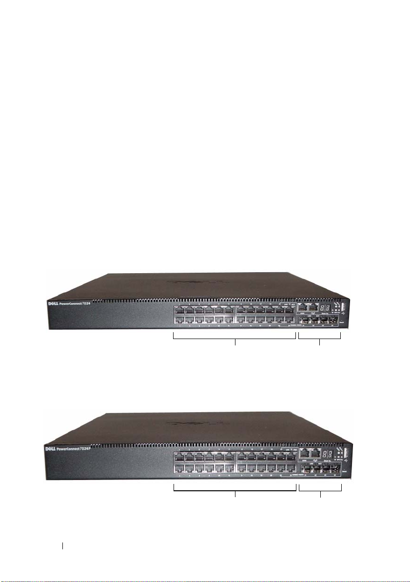
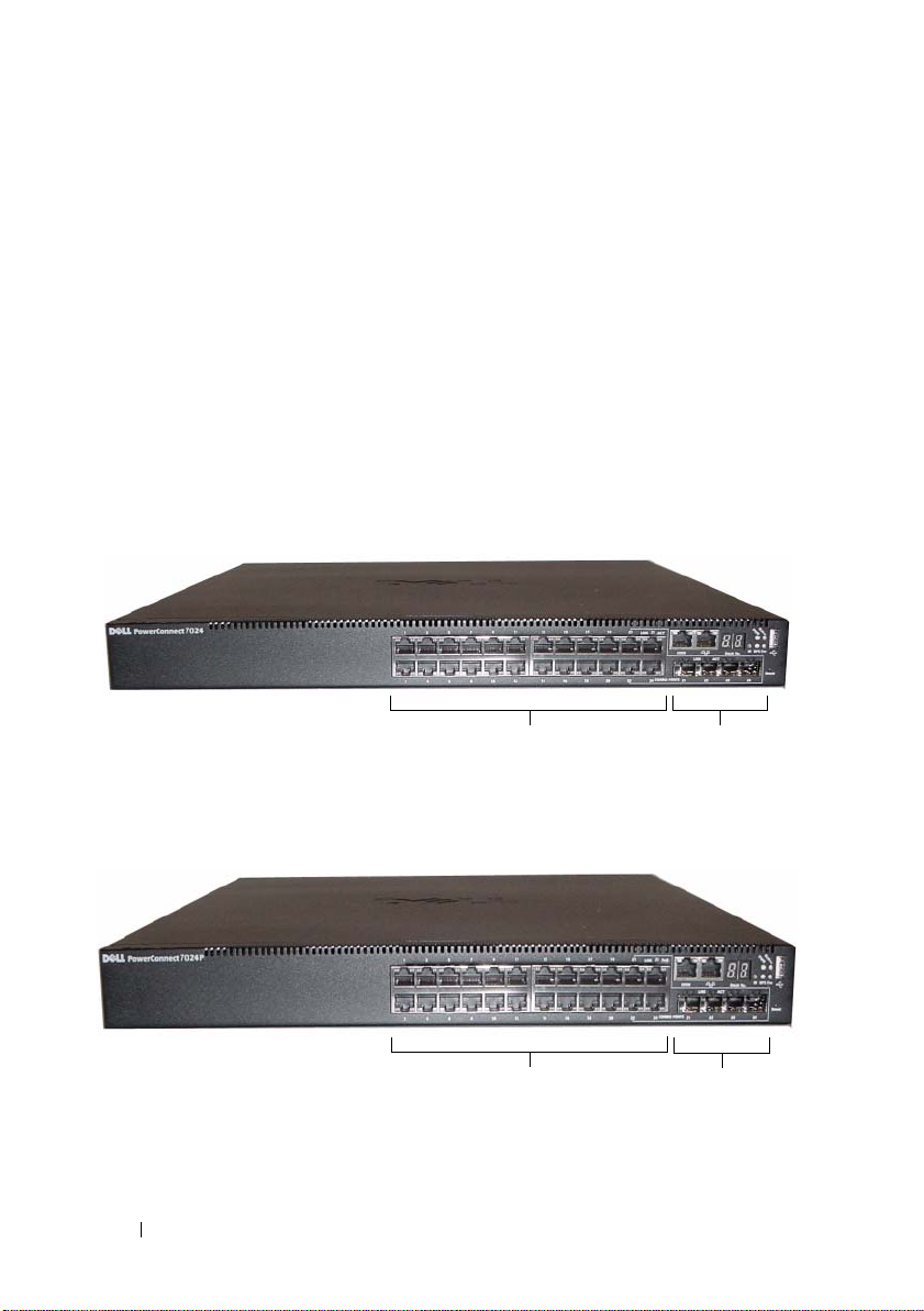
PowerConnect 7000 Series Front Panel
The following images show the front panels of the six switch models in the
PowerConnect 7000 Series.
Figure 1-1. PowerConnect 7024 with 24 10/100/1000BASE-T Ports
Combo Ports10/100/1000BASE-T Auto-sensing
Full Duplex RJ-45 Ports
Figure 1-2. PowerConnect 7024P with 24 10/100/1000BASE-T PoE Plus Ports
Combo Ports10/100/1000BASE-T RJ-45 PoE Plus Ports
Providing up to 30W per Port
6 Getting Started Guide
Page 9
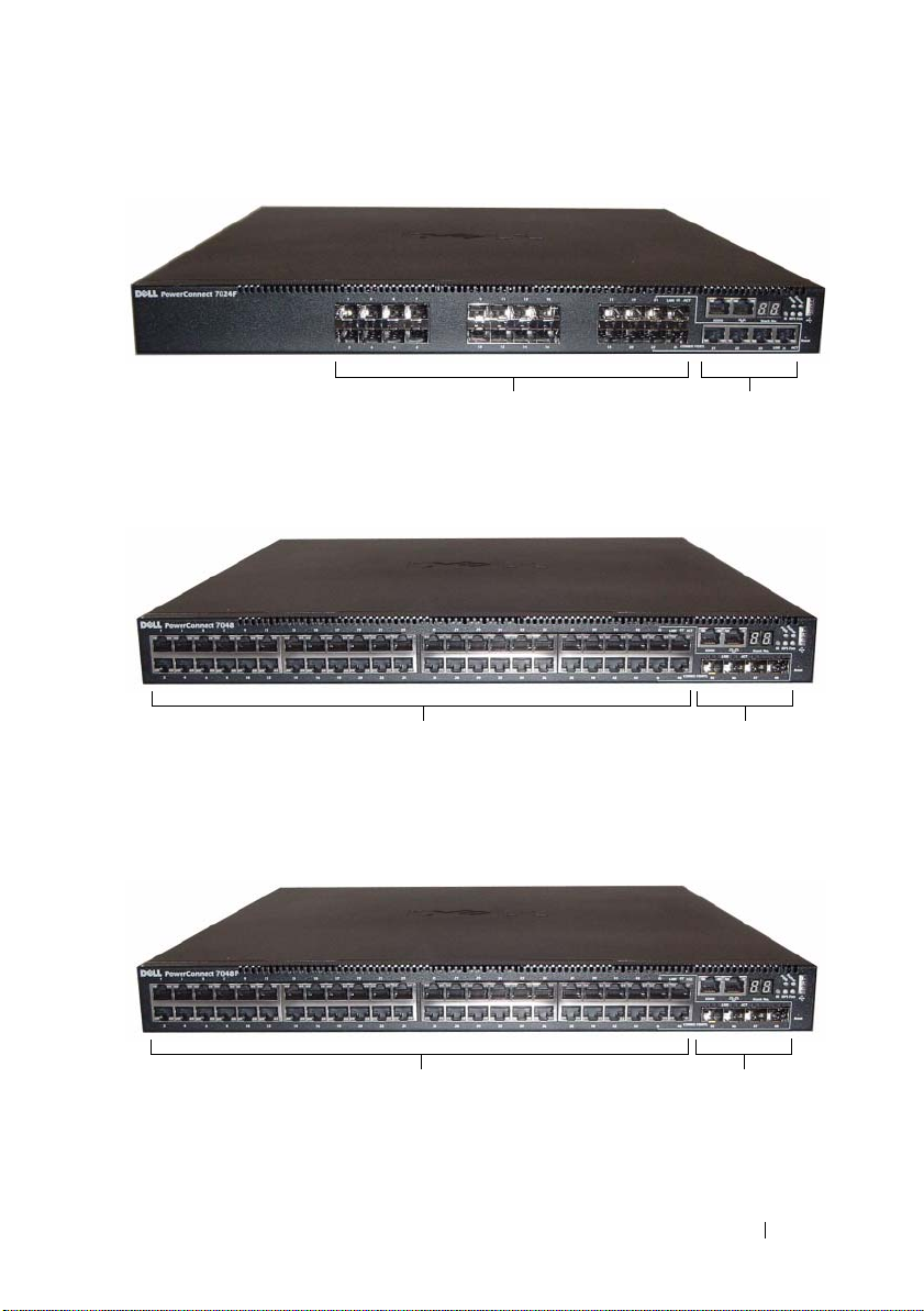
Figure 1-3. PowerConnect 7024F with 24 SFP Ports
SFP Ports Combo Ports
Figure 1-4. PowerConnect 7048 with 48 10/100/1000BASE-T Ports
Full Duplex RJ-45 Ports
Combo Ports10/100/1000BASE-T Auto-sensing
Figure 1-5. PowerConnect 7048P with 48 10/100/1000BASE-T PoE Plus Ports
Combo Ports10/100/1000BASE-T RJ-45 PoE Plus Ports
Providing up to 30W per Port
Getting Started Guide 7
Page 10
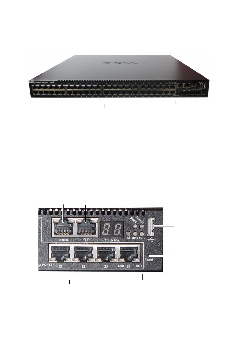
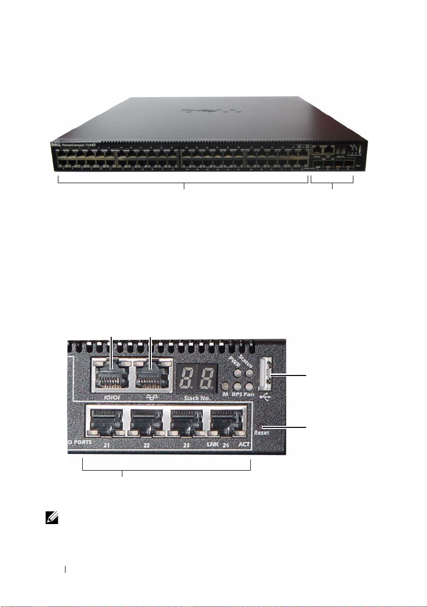
Figure 1-6. PowerConnect 7048R with 48 10/100/1000BASE-T Ports
10/100/1000BASE-T Auto-sensing
Full Duplex RJ-45 Ports
Combo Ports
In addition to the switch ports, the front panel of each model in the series
includes the following ports:
• Console port
• Out-of-band management port
• USB port
The additional ports are on the right side of the front panel.
Figure 1-7. Additional PowerConnect 7000 Series Ports
Console Port Out-of-Band Management Port
USB Port
Reset Button
Combo Ports
8 Getting Started Guide
Page 11

The front panel also contains a reset button (pinhole) and several status
LEDs.
NOTE: The port LEDs and system LEDs on the front panel are not the same for all
models. Figure 1-7 shows the LEDs on the PowerConnect 7024, PowerConnect
7024F, and PowerConnect 7048 switches.
Switch Ports
The PowerConnect 7024 and PowerConnect 7024P front panel provides
24 Gigabit Ethernet (10/100/1000BASE-T) RJ-45 ports with four SFP combo
ports that have an auto-sensing mode for speed, flow control, and duplex
mode. SFP transceivers are sold separately. The PowerConnect 7024P switch
ports are IEEE 802.3at-2009-compliant (PoE Plus) and can provided up to
30W of power per port.
The PowerConnect 7024F front panel provides 20 Gigabit Ethernet
(10/100/1000BASE-FX) SFP ports plus 4 combo ports for copper or SFP
media support.
The PowerConnect 7048, PowerConnect 7048P, and PowerConnect 7048R
front panel provides 48 Gigabit Ethernet (10/100/1000BASE-T) RJ-45 ports
with four SFP combo ports. The PowerConnect 7048P switch ports are
IEEE 802.3at-2009-compliant (PoE Plus) and can provided up to 30W of
power per port.
The front-panel switch ports have the following characteristics:
• The switch automatically detects the difference between crossed and
straight-through cables on RJ-45 ports.
• SFP ports support both SX and LX modules.
• RJ-45 ports support half- and full-duplex mode 10/100/1000 Mbps.
Console Port
The console port is for management through a serial interface. This port
provides a direct connection to the switch and allows you to access the CLI
from a console terminal connected to the port through the provided serial
cable (RJ-45 to female DB-9 connectors).
The console port supports asynchronous data of eight data bits, one stop bit, no
parity bit, and no flow control. The default baud rate is 9600 bps.
Getting Started Guide 9
Page 12

Out-of-Band Management Port
The Out-of-Band (OOB) management port is a 10/100/1000BASE-T
Ethernet port dedicated to remote switch management. Traffic on this port is
segregated from operational network traffic on the switch ports and cannot be
switched or routed to the operational network.
USB Port
The Type-A, female USB port supports a USB 2.0-compliant flash memory
drive. The PowerConnect switch can read or write to a flash drive formatted
as FAT-32. You can use a USB flash drive to copy switch configuration files
and images between the USB flash drive and the switch. You can also use the
USB flash drive to move and copy configuration files and images from one
switch to other switches in the network.
The USB port does not support any other type of USB device.
Reset Button
The reset button is accessed through the pinhole and allows you to perform a
hard reset on the switch. To use the reset button, insert an unbent paper clip
or similar tool into the pinhole. When the switch completes the boot process
after the reset, it resumes operation with the most recently saved
configuration. Any changes made to the running configuration that were not
saved to the startup configuration prior to the reset are lost.
Port and System LEDs
The front panel contains light emitting diodes (LEDs) that indicate the
status of port links, power supplies, fans, stacking, and the overall system.
Additionally, the PowerConnect 7024P and PowerConnect 7048P switches
contain LEDs that provide information about Power over Ethernet Plus
(PoE+) status and activity on the ports.
For information about the status that the LEDs indicate, see the User’s
Configuration Guide.
10 Getting Started Guide
Page 13
Stack Master LED and Stack Number Display
When a switch within a stack is the master unit, the stack master LED, which
is labeled M, is solid green. If the M LED is off, the stack member is not the
master unit. The Stack No. panel displays the unit number for the stack
member. If a switch is not part of a stack, the M LED is illuminated and the
stack unit number is 1.
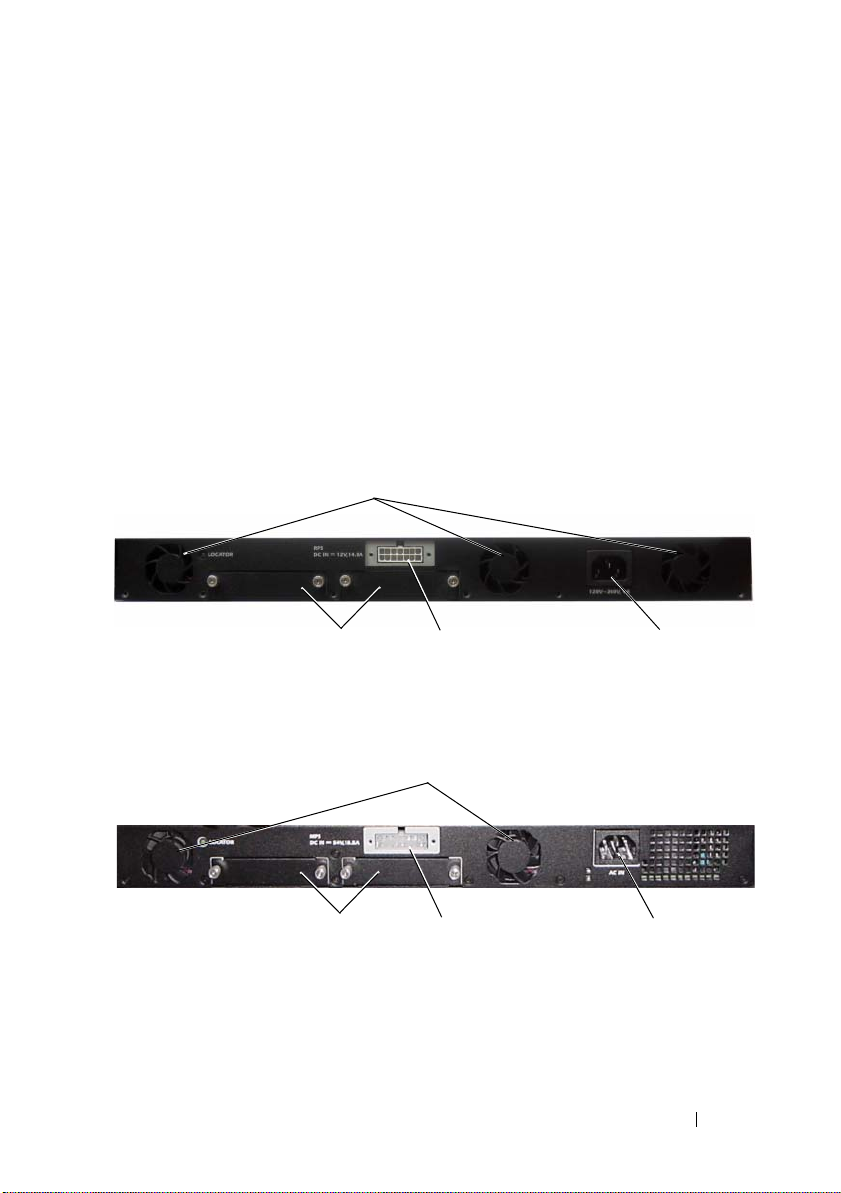
PowerConnect 7000 Series Back Panel
The following images show the back panel of the PowerConnect 7000 Series
switches.
Figure 1-8. PC7024, PC7024F, and PC7048 Back Panel
Fan Vents
Dual 10G Slots for SFP+, 10GBASE-T,
or Stacking/10GbE Modules
Figure 1-9. PC7024P and PC7048P Back Panel
Fan Vents
Dual 10G Slots for SFP+, 10GBASE-T,
or Stacking/10 GbE Modules
Redundant DC Power
Supply Receptacle
External DC Power
Supply Receptacle
Getting Started Guide 11
AC Power
Receptacle
AC Power
Receptacle
Page 14
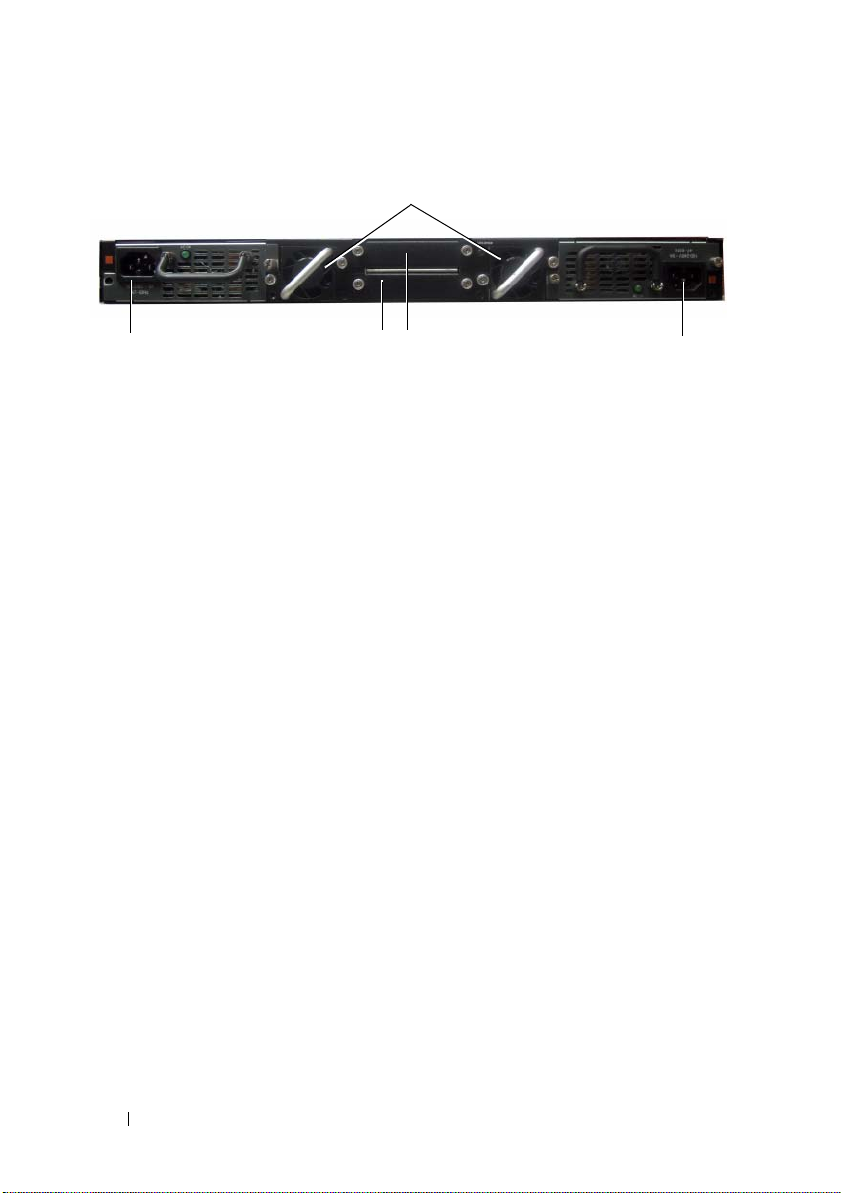
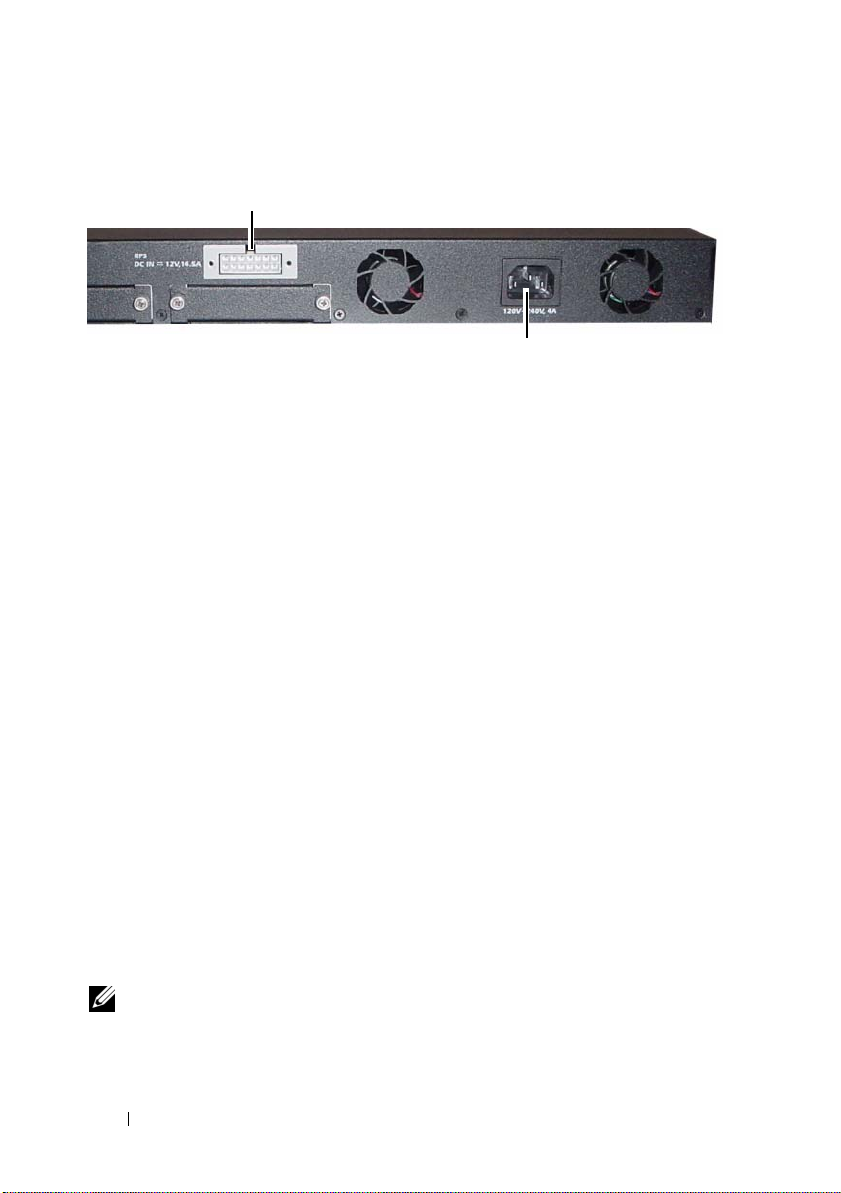
Figure 1-10. PC7048R Back Panel
Fan Trays
AC Power
Receptacle
Dual 10G Slots for SFP+, 10GBASE-T,
or Stacking/10GbE Modules
AC Power
Receptacle
Expansion Slots for Plug-in Modules
Two expansion slots are located on the back of the switch and can support the
following modules:
• 10GBASE-T module
• SFP+ module
• Stacking/10 GbE module
Each plug-in module has two ports. The Stacking/10GbE modules can be
configured to operate as either 16-Gigabit stacking ports or 10-Gigabit
Ethernet switch ports. The plug-in modules include hot-swap support, so you
do not need to reboot the switch after you install a new module.
Power Supplies
PC7024 and PC7024F
PowerConnect 7024 and PowerConnect 7024F switches have an internal
180-watt power supply. The additional external power supply (PowerConnect
RPS720) provides 180 watts of power and gives full redundancy for the
switch.
PC7024P
PowerConnect 7024P switches have an internal 1000-watt power supply.
The additional external power supply (PowerConnect MPS1000) provides
1000 Watts and gives full redundancy for the switch.
12 Getting Started Guide
Page 15

PC7048
PowerConnect 7048 switches have an internal 180-watt power supply.
The additional external power supply (PowerConnect RPS720) provides
180 watts and gives full redundancy for the switch.
PC7048P
PowerConnect 7048P switches have an internal 1000-watt power supply
which can support up to 24 ports of PoE. The additional external power
supply (PowerConnect MPS1000) allows all 48 ports of PoE, or 24 ports of
PoE and full redundancy for the switch.
PC7048R and PC7048R-RA
PowerConnect 7048R and PowerConnect 7048R-RA switches are designed as
top-of-rack switches and include two internal, replaceable, AC power supplies
for redundant or load-sharing operation. Each power supply can provide
300 watts and includes hot-swap support. This means you do not need to
power-down the switch to remove or replace one power supply while the other
power supply is operating normally. However, it is necessary to remove power
from the power supply that is being removed or replaced.
CAUTION: Remove the power cable from the modules prior to removing the
module itself. Power must not be connected prior to insertion in the chassis.
Ventilation System
Three fans cool the PowerConnect 7024, PowerConnect 7024F, and
PowerConnect 7048. The PowerConnect 7024P and PowerConnect 7048P
each have two fans, with a third fan in the internal power supply.
The PowerConnect 7048R has two hot-swappable fan trays with one fan each.
Locator LED
The back panel includes an LED to help identify the switch within a rack or
room full of switches. From your remote management system, you can set the
LED to blink to help you or a local technician identify the physical location of
the switch.
Getting Started Guide 13
Page 16

Installation
Site Preparation
PowerConnect 7000 Series switches can be mounted in a standard 48.26-cm
(19-inch) rack or left freestanding (placed on a flat surface) and function as
stand-alone switches.
Before installing the switch or switches, make sure that the chosen
installation location meets the following site requirements:
•
Power
— The switch is installed near an easily accessible 100–240 VAC,
50–60 Hz outlet.
•
Clearance
access. Allow clearance for cabling, power connections, and ventilation.
Cabling
•
as radio transmitters, broadcast amplifiers, power lines, and fluorescent
lighting fixtures.
•
Ambient Temperature
range is 0 to 45ºC (32 to 113ºF) at a relative humidity of up to 95 percent,
non-condensing.
Unpacking the Switch
— There is adequate front and rear clearance for operator
— The cabling is routed to avoid sources of electrical noise such
— The ambient switch operating temperature
Package Contents
When unpacking each switch, make sure that the following items are
included:
• One PowerConnect switch
• One AC power cable (two AC power cables for the PowerConnect 7048R)
• One RJ-45 to DB-9 female cable
• One rack-mount kit for rack installation (two mounting brackets, bolts,
and cage nuts)
• One set of self-adhesive rubber pads for the free-standing switch (four pads
are included)
•
User Documentation
14 Getting Started Guide
CD
Page 17
• Getting Started Guide
• Safety and Regulatory Information
• Warranty and Support Information
• Software License Agreement
Unpacking Steps
NOTE: Before unpacking the switch, inspect the container and immediately report
any evidence of damage.
1
Place the container on a clean, flat surface and cut all straps securing the
container.
2
Open the container or remove the container top.
3
Carefully remove the switch from the container and place it on a secure
and clean surface.
4
Remove all packing material.
5
Inspect the product and accessories for damage.
Mounting the Switch
WARNING: Read the safety information in the Safety and Regulatory Information
as well as the safety information for other switches that connect to or support the
switch.
The AC power connector is on the back panel of the switch.
Installing in a Rack
WARNING: Do not use rack mounting kits to suspend the switch from under a
table or desk, or attach it to a wall.
CAUTION: Disconnect all cables from the switch before continuing. Remove all
self-adhesive pads from the underside of the switch, if they have been attached.
CAUTION: When mounting multiple switches into a rack, mount the switches
from the bottom up.
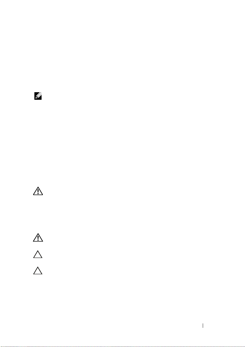
1
Place the supplied rack-mounting bracket on one side of the switch,
ensuring that the mounting holes on the switch line up to the mounting
holes in the rack-mounting bracket. Figure 1-11 illustrates where to mount
the brackets.
Getting Started Guide 15
Page 18
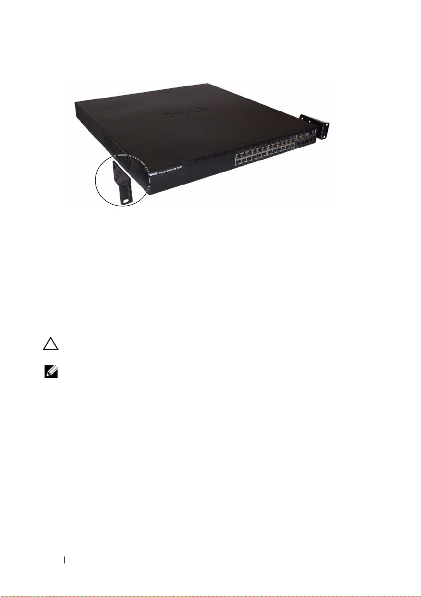
Figure 1-11. Attaching the Brackets
2
Insert the supplied bolts into the rack-mounting holes and tighten with a
screwdriver.
3
Repeat the process for the rack-mounting bracket on the other side of the
switch.
4
Insert the switch into the 48.26 cm (19 inch) rack, ensuring that the rackmounting holes on the switch line up to the mounting holes in the rack.
5
Secure the switch to the rack with either the rack bolts or cage nuts and
cage-nut bolts with washers (depending on the kind of rack you have).
Fasten the bolts on bottom before fastening the bolts on top.
CAUTION: Make sure that the supplied rack bolts fit the pre-threaded holes in the
rack.
NOTE: Make sure that the ventilation holes are not obstructed.
16 Getting Started Guide
Page 19

Installing as a Free-standing Switch
NOTE: We strongly recommend mounting the switch in a rack.
Install the switch on a flat surface if you are not installing it in a rack.
The surface must be able to support the weight of the switch and the switch
cables. The switch is supplied with four self-adhesive rubber pads.
1
Attach the self-adhesive rubber pads on each location marked on the
bottom of the switch.
2
Set the switch on a flat surface, and make sure that it has proper
ventilation by leaving 5 cm (2 inches) on each side and 13 cm (5 inches) at
the back.
Stacking Multiple Switches
You can stack PowerConnect PowerConnect 7000 Series switches up to
12 switches high, supporting up to 576 front panel ports. When multiple
switches are connected together through the stack ports, they operate as a
single unit with a larger port count. The stack operates and is managed as a
single entity.
NOTE: If you are installing a stack of switches, you need to assemble and cable the
stack before powering up and configuring it. When a stack is powered up for the
first time, the switches elect a Master Switch, which may occupy any location in
the stack. The Master LED on the front panel is illuminated on the master unit.
Creating a Switch Stack
Create a stack by connecting adjacent units using the stacking ports on the
back panel of the switch. Stacking modules are sold separately. Figure 1-12
shows the switches connected in a ring topology, which is the recommended
topology for a stack.
Install a separately purchased stacking module in one of the rear expansion
1
slots for each of the switches in the stack.
2
Connect one of the short stacking cables into either of the stacking ports
of the top switch and the switch directly below it.
If necessary, use a separately purchased, long (3 meter) stacking cable to
connect the switches.
Getting Started Guide 17
Page 20
3
Repeat this process until all of the devices are connected.
4
Use the remaining stacking cable to connect the remaining free ports,
one each on the top and bottom switches.
Figure 1-12. Connecting a Stack of Switches
XG1 Port XG2 Port
Unit 1
Unit 2
Unit 3
The stack in Figure 1-12 is connected in a ring topology and has the following
physical connections between the switches:
• The XG1 port on Unit 1 is connected to the XG2 port on Unit 2.
• The XG1 port on Unit 2 is connected to the XG4 port on Unit 3.
• The XG3 port on Unit 3 is connected to the XG2 port on Unit 1.
Stacking Standby
The stacking feature supports a Standby or backup unit that assumes the
Master unit role if the Master unit in the stack fails. As soon as a Master
failure is detected in the stack, the Standby unit initializes the control plane
and enables all other stack units with the current configuration. The Standby
unit maintains a synchronized copy of the running configuration for the
stack. During switchover, all the ports are brought down and brought up to
avoid possible loops and to get new master software applications to a
consistent state.
The Standby unit is pre-configured in the stack; however, you can use the CLI
to select a different stack member as Standby. See the User’s Configuration
Guide or the CLI Reference Guide for more information.
18 Getting Started Guide
Page 21
Starting and Configuring the Switch
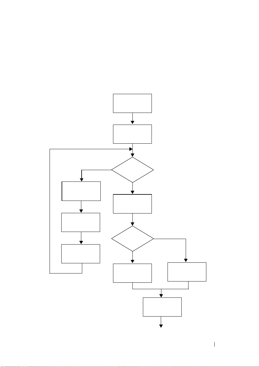
The following flow chart provides an overview of the steps you use to perform
the initial configuration after the switch is unpacked and mounted.
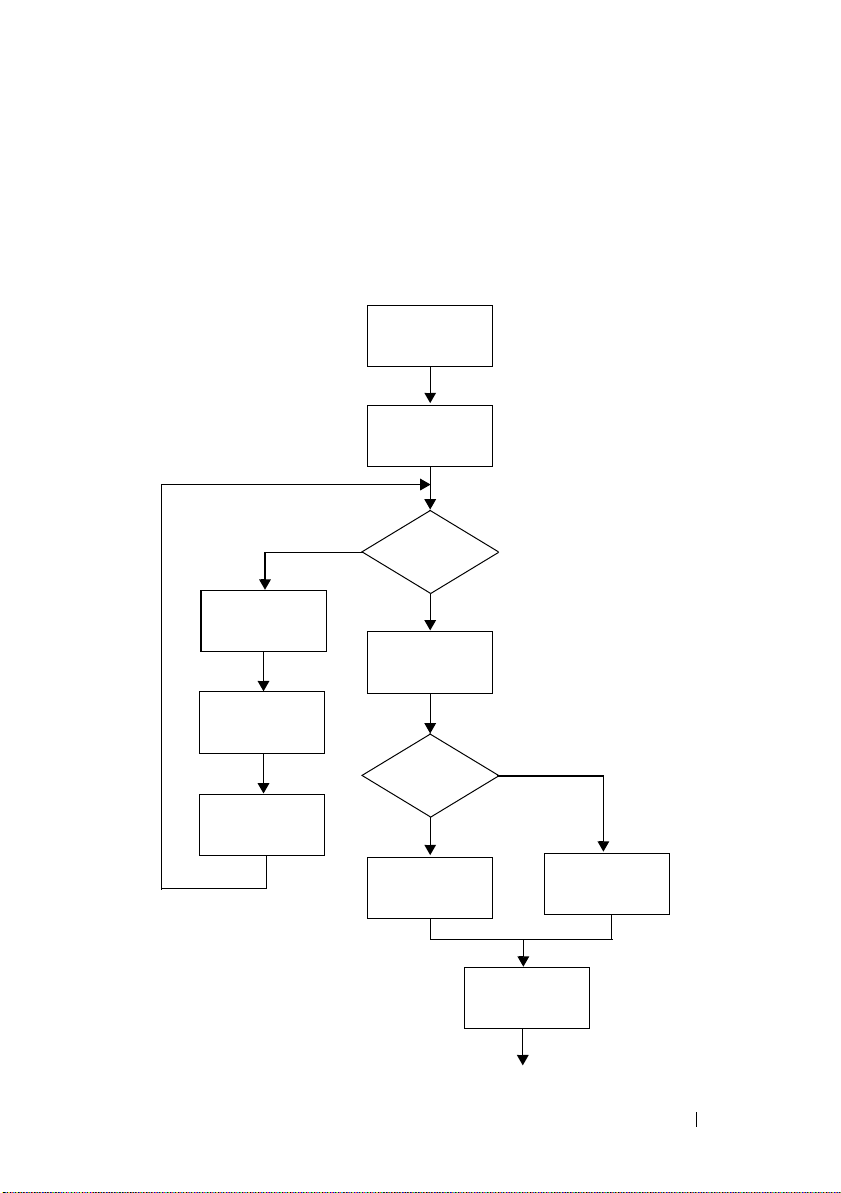
Figure 1-13. Installation and Configuration Flow Chart
Connect Power
and Console
Power On
Yes
Choose Option 2
Boot Menu
(Special Functions)
Reboot
Enter Boot
Menu?
No
Loading Program
from Flash to RAM
Enter
Wizard?
No
Manual Initial
Configuration
Yes
Easy Setup Wizard
Configuration
Advanced
Configuration
Getting Started Guide 19
Page 22

Connecting a Switch to a Terminal
After completing all external connections, connect a terminal to a switch to
configure the switch.
NOTE: Read the release notes for this product before proceeding. You can
download the release notes from the Dell Support website at
support.dell.com/manuals.
NOTE: We recommend that you obtain the most recent version of the user
documentation from the Dell Support website at support.dell.com/manuals.
To monitor and configure the switch via serial console, use the console port
on the front panel of the switch (see Figure 1-14) to connect it to a VT100
terminal or to a computer running VT100 terminal emulation software. The
console port is implemented as a data terminal equipment (DTE) connector.
The following equipment is required to use the console port:
• VT100-compatible terminal or a desktop or a portable computer with a
serial port running VT100 terminal emulation software,
HyperTerminal.
• A serial cable (provided) with an RJ-45 connector for the console port and
DB-9 connector for the terminal.
Perform the following tasks to connect a terminal to the switch console port:
1
Connect the DB-9 connector on the serial cable to the terminal or
computer running VT100 terminal emulation software.
2
Configure the terminal emulation software as follows:
a
Select the appropriate serial port (for example, COM 1) to connect to
the console.
b
Set the data rate to 9600 baud.
c
Set the data format to 8 data bits, 1 stop bit, and no parity.
d
Set the flow control to none.
e
Set the terminal emulation mode to
VT100
.
such as Microsoft
20 Getting Started Guide
Page 23
f
Select Terminal keys for Function, Arrow, and Ctrl keys. Make sure
that the setting is for Terminal keys (not Microsoft Windows keys).
NOTE: When using HyperTerminal with Microsoft Windows 2000, make sure
that you have Windows 2000 Service Pack 2 or later installed. With Windows
2000 Service Pack 2, the arrow keys function properly in HyperTerminal's
VT100 emulation. Go to microsoft.com for more information about Windows
2000 service packs.
3
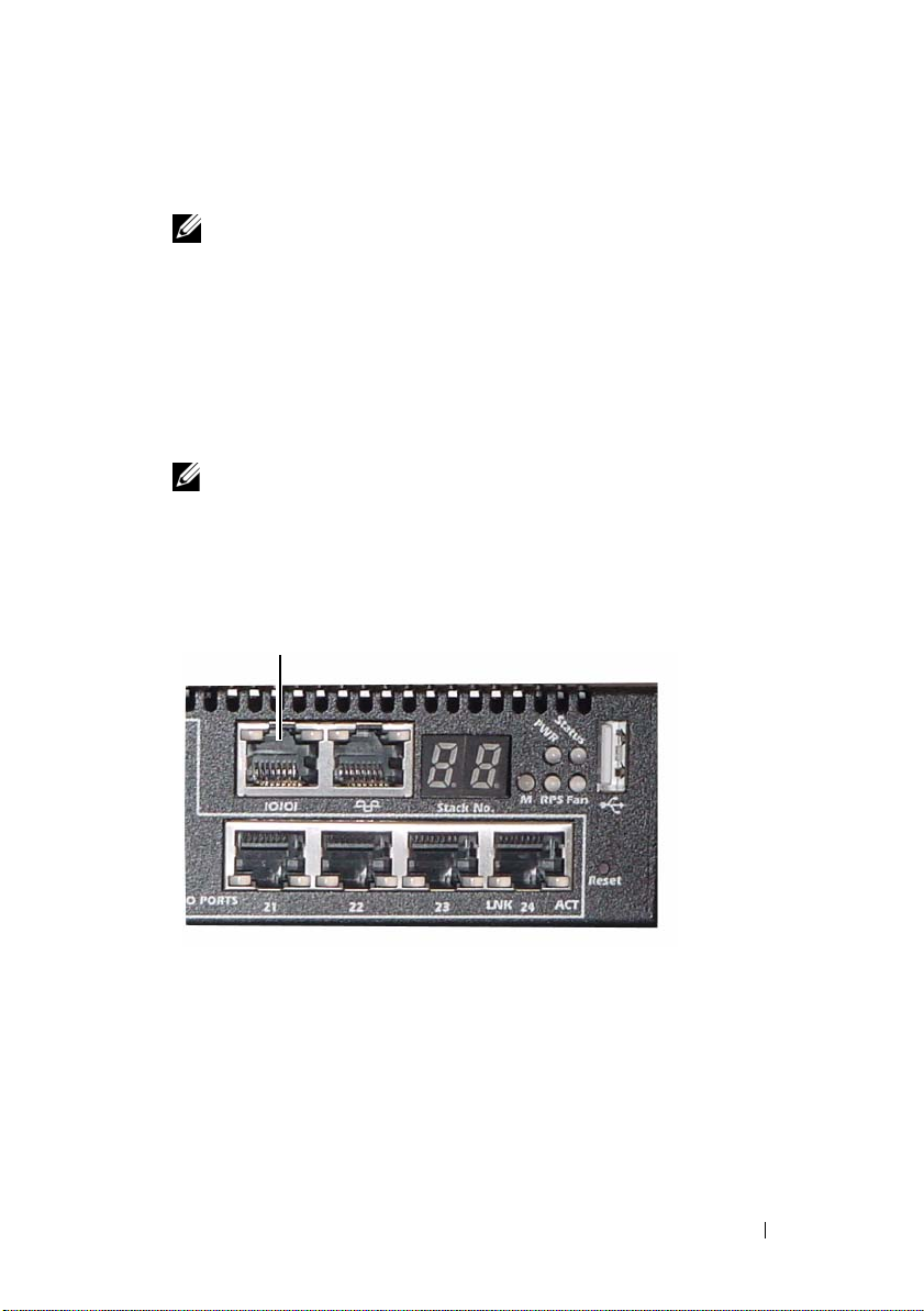
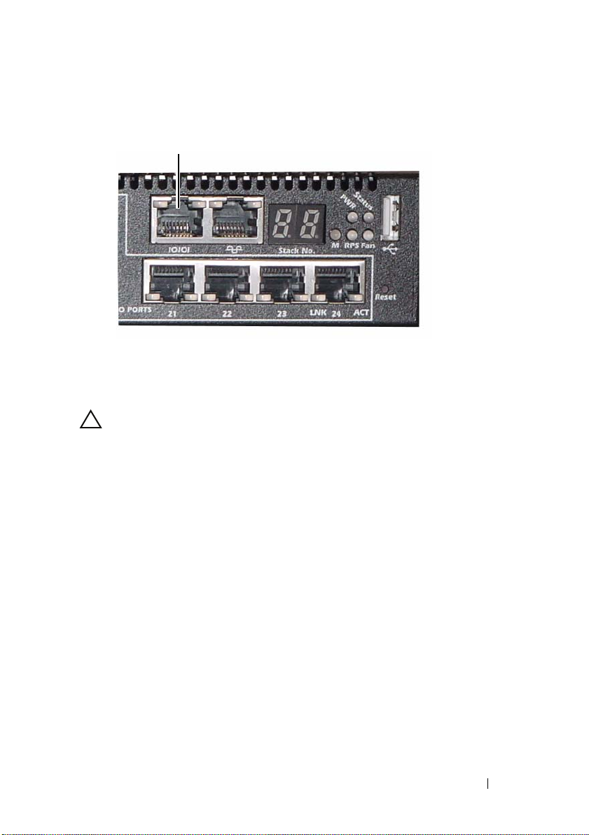
Connect the RJ-45 connector on the cable directly to the switch console
port. The PowerConnect 7000 Series console port is located on the right
side of the front panel and is labeled with a
|O|O|
symbol, as shown in
Figure 1-14.
NOTE: If you are configuring a stack of switches, connect the serial cable to
the console port of the Master switch. If you connect the terminal to a
subordinate switch, you will not be able to use the CLI.
Figure 1-14. Console Port Location
Console Port
The RJ-45 port to the right of the console port is for out-of-band
management.
Getting Started Guide 21
Page 24
Connecting a Switch to a Power Supply
CAUTION: Read the safety information in the Safety and Regulatory Information
as well as the safety information for other switches that connect to or support the
switch.
The PowerConnect 7048R switch has two power supplies for redundant or
load-sharing operation. All other models in the PowerConnect 7000 Series
have one power supply. The
AC and DC Power Connection
1
Make sure that the switch console port is connected to a VT100 terminal
or VT100 terminal emulator via the RJ-45 to DB-9 female cable.
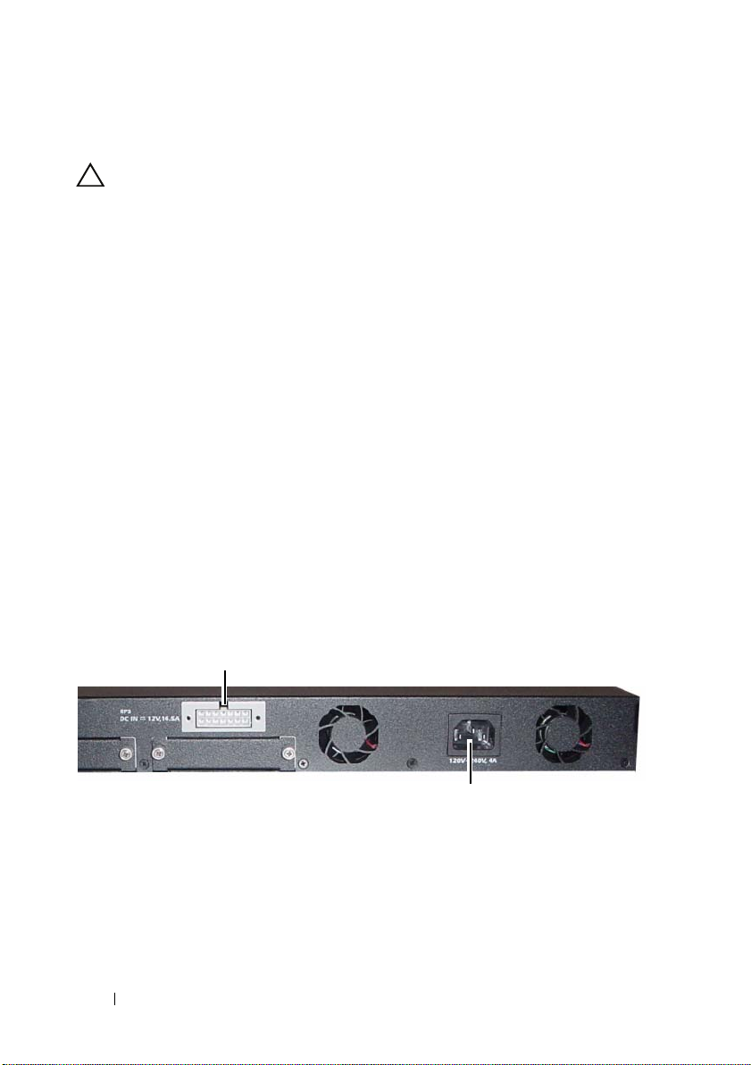
2
Using a 5-foot (1.5 m) standard power cable with safety ground connected,
connect the power cable to the AC main receptacle located on the back
panel (see Figure 1-15).
3
Connect the power cable to a grounded AC outlet.
4
If you are using a redundant or external DC power supply, such as the
PowerConnect RPS720 or PowerConnect MPS1000, connect the DC
power cable to the DC receptacle located on the back panel (see
Figure 1-15).
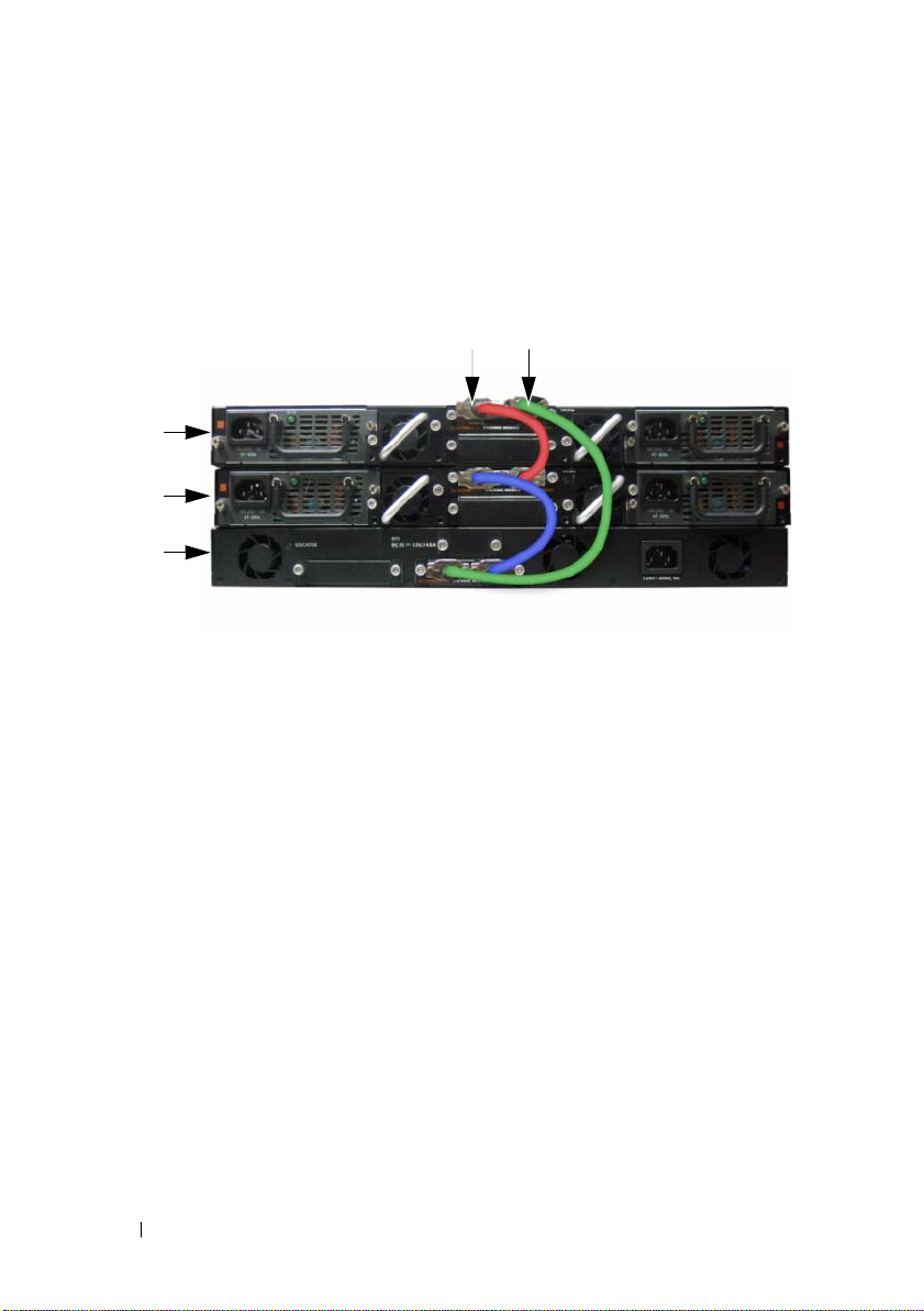
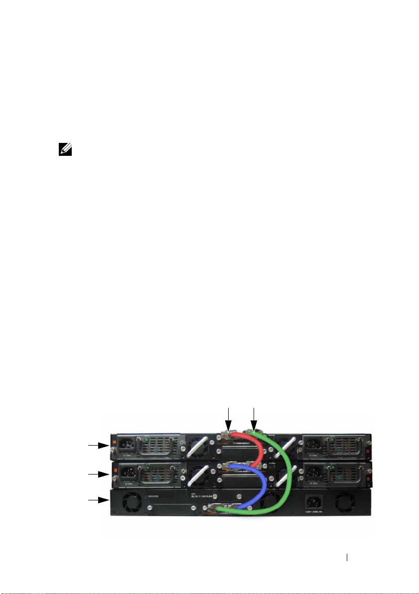
Figure 1-15. AC and DC Power Connection to Switch
To DC Power Source (Optional)
power receptacles are on the back panel.
22 Getting Started Guide
To AC Power Source
Page 25

Booting the Switch
When the power is turned on with the local terminal already connected, the
switch goes through a power-on self-test (POST). POST runs every time the
switch is initialized and checks hardware components to determine if the
switch is fully operational before completely booting. If POST detects a
critical problem, the program flow stops. If POST passes successfully, valid
firmware is loaded into RAM. POST messages are displayed on the terminal
and indicate test success or failure. The boot process runs for approximately
60 seconds.
You can invoke the Boot menu after the first part of the POST is completed.
From the Boot menu, you can perform configuration tasks such as resetting
the system to factory defaults, activating the backup image, or recovering a
password. For more information about the Boot menu functions, see the CLI
Reference Guide.
Performing the Initial Configuration
The initial configuration procedure is based on the following assumptions:
• The PowerConnect switch was never configured before and is in the same
state as when you received it.
• The PowerConnect switch booted successfully.
• The console connection was established, and the Dell Easy Setup Wizard
prompt appears on the screen of a VT100 terminal or terminal equivalent.
The initial switch configuration is performed through the console port. After
the initial configuration, you can manage the switch from the alreadyconnected console port or remotely through an interface defined during the
initial configuration.
NOTE: The switch is not configured with a default user name, password,
or IP address.
Before setting up the initial configuration of the switch, obtain the following
information from your network administrator:
• The IP address to be assigned to the management interface.
• The IP subnet mask for the network.
• The IP address of the management interface default gateway.
These settings are necessary to allow the remote management of the switch
through Telnet (Telnet client) or HTTP (Web browser).
Getting Started Guide 23
Page 26

Enabling Remote Management
The front panel contains a Gigabit Ethernet port for remote out-of-band
(OOB) management. The OOB port is located to the right of the console
port. Additionally, you can use any of the switch ports on the front panel for
in-band management. By default, all in-band ports are members of VLAN 1.
The Dell Easy Setup Wizard includes prompts to configure network
information for both the OOB management interface and the VLAN 1
routing interface. For either management interface, you can assign a static
IP address and subnet mask or enable DHCP and allow a network DHCP
server to assign the information.
See the CLI Reference Guide for information about the CLI commands you
use to configure network information.
Initial Configuration Procedure
You can perform the initial configuration by using the Dell Easy Setup
Wizard or by using the CLI. The wizard automatically starts when the switch
configuration file is empty. You can exit the wizard at any point by entering
[ctrl+z], but all configuration settings specified will be discarded, and the
switch will use the default values.
NOTE: If you do not run the Easy Setup Wizard or do not respond to the initial Easy
Setup Wizard prompt within 60 seconds, the switch enters CLI mode.
For more information about performing the initial configuration by using the
CLI, see the CLI Reference Guide. This Getting Started Guide shows how to
use the Easy Setup Wizard for initial switch configuration. The wizard sets up
the following configuration on the switch:
• Establishes the initial privileged user account with a valid password.
The wizard configures one privileged user account during the setup.
• Enables CLI login and HTTP access to use the local authentication setting
only.
• Sets up the IP address for the OOB management interface.
• Sets up the IP address for the VLAN 1 routing interface, of which all
in-band ports are members.
• Sets up the SNMP community string to be used by the SNMP manager at
a given IP address. You may choose to skip this step if SNMP management
is not used for this switch.
24 Getting Started Guide
Page 27

• Allows you to specify the network management system IP address or
permit management access from all IP addresses.
• Configures the default gateway IP address for the VLAN 1 interface.
Example Session
This section describes an Easy Setup Wizard session. The following values are
used by the example session:
• The SNMP community string to be used is
• The network management system (NMS) IP address is
• The user name is
admin
, and the password is
• The OOB management interface uses
• The IP address for the VLAN 1 routing interface is
subnet mask of
• The default gateway is
255.255.255.0
10.1.1.1
.
The setup wizard configures the initial values as defined above. After
completing the wizard, the switch is configured as follows:
• SNMPv2 is enabled and the community string is set up as defined above.
SNMPv3 is disabled by default.
• The admin user account is set up as defined.
• A network management system is configured. From the management
station, you can access the SNMP, HTTP, and CLI interfaces. You may also
choose to allow all IP addresses to access these management interfaces by
choosing the (0.0.0.0) IP address.
• DHCP is enabled on the OOB management interface.
• An IP address is configured for the VLAN 1 routing interface.
• A default gateway address is configured.
public
.
10.1.2.100
admin123
DHCP
for IP address assignment.
.
10.1.1.200
.
with a
NOTE: In the example below, the possible user options or default values are
enclosed in [ ]. If you press <Enter> with no options defined, the default value is
accepted. Help text is in parentheses.
Getting Started Guide 25
Page 28

The following example contains the sequence of prompts and responses
associated with running an example Dell Easy Setup Wizard session, using
the input values listed above.
After the switch completes the POST and is booted, the following dialog
appears:
Unit 1 - Waiting to select management unit)>
Applying Global configuration, please wait ...
Welcome to Dell Easy Setup Wizard
The Setup Wizard guides you through the initial switch
configuration, and gets you up and running as quickly
as possible. You can skip the setup wizard, and enter
CLI mode to manually configure the switch. You must
respond to the next question to run the setup wizard
within 60 seconds, otherwise the system will continue
with normal operation using the default system
configuration. Note: You can exit the setup wizard at
any point by entering [ctrl+z].
Would you like to run the setup wizard (you must
answer this question within 60 seconds)? [Y/N] y
Step 1:
The system is not setup for SNMP management by
default. To manage the switch using SNMP (required for
Dell Network Manager) you can
. Set up the initial SNMP version 2 account now.
. Return later and setup other SNMP accounts. (For
more information on setting up an SNMP version 1 or
3 account, see the user documentation).
Would you like to setup the SNMP management interface
now? [Y/N] y
26 Getting Started Guide
Page 29

To setup the SNMP management account you must specify
the management system IP address and the "community
string" or password that the particular management
system uses to access the switch. The wizard
automatically assigns the highest access level
[Privilege Level 15] to this account. You can use Dell
Network Manager or other management interfaces to
change this setting, and to add additional management
system information later. For more information on
adding management systems, see the user documentation.
To add a management station:
Please enter the SNMP community string to be used.
[public]: public
NOTE: If it is configured, the default access level is set to the highest available
access for the SNMP management interface. Initially only SNMPv2 will be
activated. SNMPv3 is disabled until you return to configure security access for
SNMPv3 (e.g. engine ID, view, etc.).
Please enter the IP address of the Management System
(A.B.C.D) or wildcard (0.0.0.0) to manage from any
Management Station. [0.0.0.0]: 10.1.2.100
Step 2:
Now we need to setup your initial privilege (Level 15)
user account. This account is used to login to the CLI
and Web interface. You may setup other accounts and
change privilege levels later. For more information on
setting up user accounts and changing privilege
levels, see the user documentation.
To setup a user account:
Please enter the user name. [root]:admin
Please enter the user password: ********
Please reenter the user password: ********
Getting Started Guide 27
Page 30

Step 3:
Next, IP addresses are setup on the OOB (Out-Of-Band)
Interface and/or the VLAN 1 routing interface.
You can use these IP addresses to access the CLI, Web
interface, or SNMP interface of the switch.
To access the switch through any Management Interface
you can
. Setup the IP address for the Management Interface.
. Setup the default gateway if IP address is manually
configured on both routing and OOB interface.
Would you like to setup the Out-Of-Band interface now?
[Y/N] y
Please enter the IP address of the device (A.B.C.D) or
enter "DHCP" (without the quotes) to automatically
request an IP address from the network DHCP server.
[192.168.2.1]: dhcp
Step 4:
Would you like to setup the VLAN1 routing interface
now? [Y/N] y
Please enter the IP address of the device (A.B.C.D) or
enter "DHCP" (without the quotes) to automatically
request an IP address from the network DHCP server:
10.1.1.200
Please enter the IP subnet mask (A.B.C.D or /nn):
255.255.255.0
Step 5:
Finally, setup the default gateway. Please enter the
IP address of the gateway from which this network is
reachable. [0.0.0.0]: 10.1.1.1
28 Getting Started Guide
Page 31

This is the configuration information that has been
collected:
SNMP Interface = "public"@10.1.2.100
User Account setup = admin
Password = ********
Out-of-band IP address = DHCP
VLAN1 Router Interface IP = 10.1.1.200 255.255.255.0
Default Gateway = 10.1.1.1
Step 6:
If the information is correct, please enter (Y) to
save the configuration and copy the settings to the
start-up configuration file. If the information is
incorrect, enter (N) to discard the configuration and
restart the wizard: [Y/N] y
Thank you for using the Dell Easy Setup Wizard.
You will now enter CLI mode.
Applying Interface configuration, please wait ...
Next Steps
After completing the initial configuration described in this section, you can
connect the OOB port to your management network for out-of-band remote
management, or you can connect any of the front-panel switch ports to your
production network for in-band remote management.
If you specified DHCP for the OOB or VLAN 1 management interface
IP address, the interface will acquire its IP address from a DHCP server on the
network. To discover the dynamically-assigned IP address, use the console
port connection to issue the following commands:
• For the OOB interface, enter
• For the VLAN 1 routing interface, enter
To access the Dell OpenManage Switch Administrator interface, enter the
OOB or VLAN 1 management interface IP address into the address field of a
Web browser. For remote management access to the CLI, enter the OOB or
VLAN 1 management interface IP address into a Telnet or SSH client.
Alternatively, you can continue to use the console port for local CLI access to
the switch.
show ip interface out-of-band
show ip interface
.
.
Getting Started Guide 29
Page 32

Your PowerConnect 7000 Series switch supports basic switching features such
as VLANs and spanning tree protocol, as well as advanced Layer 3 features
such as dynamic routing and multicast. Use the Web-based management
interface or the CLI to configure the features your network requires.
For information about how to configure the switch features, see the
User’s Configuration Guide or CLI Reference Guide included on the
User Documentation CD or available on the support site:
support.dell.com/manuals.
PoE Power Budget
The following PoE power budget information is provided to comply with
regulatory testing requirements.
Power Supply
Type/Watts
Only AC 180 watts 720 watts 180 watts 720 watts
Only MPS 180 watts 720 watts 180 watts 720 watts
AC and MPS 180 watts 720 watts 180 watts 1440 watts
PowerConnect 7024P PowerConnect 7048P
Power allocated
for non-PoE
system (watts)
Power allocated
for PoE system
(watts)
Power allocated
for non-PoE
system (watts)
Power allocated
for PoE system
(watts)
30 Getting Started Guide
Page 33

Dell PowerConnect 7000 系列
交换机
使用入门指南
管制型号:
PC7024、PC7024P、PC7024F
PC7048、PC7048P、PC7048R 和 PC7048R-RA
、
Page 34

注、小心和警告
注:“注”表示可以帮助您更好地使用计算机的重要信息。
小心:“小心”表示如果不遵循说明,就有可能损坏硬件或导致数据
丢失。
警告:
____________________
“警告”表示可能会导致财产损失、人身伤害甚至死亡。
本出版物中的信息如有更改,恕不另行通知。
© 2011 Dell Inc.
未经
Dell Inc.
本文中使用的商标:
的商标。
Microsoft Corporation
本出版物中述及的其它商标和产品名称是指拥有相应商标和产品名称的公司或其制造的
产品。
Dell Inc.
管制型号:
PC7024、PC7024P、PC7024F、PC7048、PC7048P、PC7048R 和 PC7048R-RA
2011 年 3 月P/N D3R71 Rev. A00
版权所有,翻印必究。
书面许可,严禁以任何形式对这些材料进行复制。
Dell™、DELL
®
、
Microsoft
Windows
在美国和/或其它国家/地区的商标或注册商标。
对本公司的商标和产品名称之外的其它商标和产品名称不拥有任何专有权。
徽标、
®
、
Windows Server
PowerConnect™ 和 OpenManage™ 是 Dell Inc.
®
、
MS-DOS
®
和 Windows Vista® 是
Page 35

目录
1 简介 . . . . . . . . . . . . . . 35
PowerConnect 7000
系列概览
. . . . . . . . . . . . . 35
2 硬件概览 . . . . . . . . . . . . 36
. . . . . . . . . . . . 36
PowerConnect 7000 系列
交换机端口 . . . . . . . . . . . . . . .
控制台端口 . . . . . . . . . . . . . . .
带外管理端口 . . . . . . . . . . . . . .
USB 端口 . . . . . . . . . . . . . . . .
重置按钮 . . . . . . . . . . . . . . . .
端口和系统 LED . . . . . . . . . . . . . . . . . . . . . . . . . . . . . . .
堆栈主交换机 LED 和堆栈编号显示 . . . . .
PowerConnect 7000
用于插入式模块的扩充槽 . . . . . . . . .
电源设备 . . . . . . . . . . . . . . . .
通风系统 . . . . . . . . . . . . . . . .
定位 LED . . . . . . . . . . . . . . . . . . . . . . . . . . . . . . . . . . . . . .
前面板
系列背面板
39
39
39
40
40
40
40
. . . . . . . . . . . . 41
42
42
43
43
目录 33
Page 36

3 安装 . . . . . . . . . . . . . . 44
现场准备 . . . . . . . . . . . . . . . . . . . . . . . . . 44
打开交换机包装
包装箱物品 . . . . . . . . . . . . . . . .
打开包装步骤 . . . . . . . . . . . . . . .
安装交换机
在机架中安装 . . . . . . . . . . . . . . .
作为独立式交换机安装 . . . . . . . . . . .
以堆栈方式安装多台交换机
创建交换机堆栈 . . . . . . . . . . . . . .
. . . . . . . . . . . . . . . . . . . . . 44
44
45
. . . . . . . . . . . . . . . . . . . . . . . 45
45
46
. . . . . . . . . . . . . . 47
47
4 启动和配置交换机. . . . . . . . . . . . . . . . . 49
将交换机连接至终端 . . . . . . . . . . . . . . . . . . 50
将交换机连接到电源设备
直流电和交流电连接 . . . . . . . . . . . .
引导交换机
进行初始配置
. . . . . . . . . . . . . . . . . . . . . . . 52
. . . . . . . . . . . . . . . . . . . . . . 52
启用远程管理 . . . . . . . . . . . . . . .
初始配置步骤 . . . . . . . . . . . . . . .
示例会话 . . . . . . . . . . . . . . . . .
接下来的步骤 . . . . . . . . . . . . . . .
. . . . . . . . . . . . . . . 51
51
53
53
54
61
5
34 目录
电源预算 . . . . . . . . . . . . . . . . . . . . . 61
PoE
Page 37

简介
本说明文件介绍有关
包括如何安装交换机并进行初始配置。有关如何配置和监测交换机功能的
信息,请参阅用户说明文件
(用户配置指南),或访问
有关说明文件及固件的最新更新。
本说明文件包含以下部分:
•
硬件概览
•
安装
•
启动和配置交换机
PowerConnect 7000
PowerConnect 7000
包括以下
•
•
•
•
•
•
注:PowerConnect 7048R (PC7048R/PC7048R-RA) 是架顶式交换机。PC7048R 和
种型号:
6
PowerConnect 7024 (PC7024)
PowerConnect 7024P (PC7024P)
PowerConnect 7024F (PC7024F)
PowerConnect 7048 (PC7048)
PowerConnect 7048P (PC7048P)
PowerConnect 7048R (PC7048R/PC7048R-RA)
PC7048R-RA 型号之间的差别在于气流的方向。
Dell PowerConnect 7000
上的《
CD
Dell 支持 Web
系列概览
系列交换机是堆栈式第
系列交换机的基本信息,
User’s Configuration Guide
站点
support.dell.com
层千兆位以太网交换机,
3
》
以获取
使用入门指南 35
Page 38

硬件概览
本节包含有关
的信息。
所有型号都是
•
440 x 460 x 44
•
17.3 x 18.1 x 1.7
PowerConnect 7000
型机架可安装交换机,具有以下物理尺寸:
1U
毫米(宽
英寸(宽
x 厚 x
PowerConnect 7000
以下图像显示了
图
1-1. PowerConnect 7024
图
1-2. PowerConnect 7024P
PowerConnect 7000
,具有
,具有
系列交换机设备特性和模块化硬件配置
高)。
高)。
x 厚 x
系列 前面板
系列的六种交换机型号的前面板。
24 个 10/100/1000BASE-T
全双工 RJ-45 端口
24 个 10/100/1000BASE-T PoE Plus
端口
组合端口10/100/1000BASE-T 自动感测
端口
36 使用入门指南
组合端口10/100/1000BASE-T RJ-45 PoE Plus 端口,
每个端口最大可提供 30W 的功率
Page 39

图
1-3. PowerConnect 7024F
,具有
24 个 SFP
端口
SFP 端口 组合端口
图
1-4. PowerConnect 7048
全双工 RJ-45 端口
图
1-5. PowerConnect 7048P
每个端口最大可提供 30W 的功率
,具有
48 个 10/100/1000BASE-T
,具有
48 个 10/100/1000BASE-T PoE Plus
端口
组合端口10/100/1000BASE-T 自动感测
端口
组合端口10/100/1000BASE-T RJ-45 PoE Plus 端口,
使用入门指南 37
Page 40
图
1-6. PowerConnect 7048R
,具有
48 个 10/100/1000BASE-T
端口
10/100/1000BASE-T 自动感测
全双工 RJ-45 端口
组合端口
除了交换机端口之外,该系列每种型号的前面板还包括以下端口:
•
控制台端口
•
带外管理端口
•
USB
端口
其它端口位于前面板的右侧。
图
前面板还包含一个针孔状重置按钮和几个状态
其它
1-7.
控制台端口 带外管理端口
注:并非所有型号的前面板上的端口 LED 和系统 LED 都相同。图 1-7 显示了
PowerConnect 7024、PowerConnect 7024F 和 PowerConnect 7048 交换机上的
LED。
PowerConnect 7000
组合端口
系列端口
LED
USB 端口
重置按钮
。
38 使用入门指南
Page 41

交换机端口
4 个 SFP
30W
SFP
模块。
前面板提供
组合端口,这些端口具有
IEEE 802.3at-2009
的功率。
(10/100/1000BASE-FX)
介质。
端口和四个
IEEE 802.3at-2009 (PoE Plus)
的半双工和全双工模式。
PowerConnect 7024 和 PowerConnect 7024P
网
(10/100/1000 Base-T) RJ-45
自动感测模式,可自动感测速率、流控制和双工模式。
出售。
PowerConnect 7024P
(PoE Plus)
PowerConnect 7024F
SFP
PowerConnect 7048
供
48
端口。
的端口,每个端口最大能提供
前面板交换机端口具有以下特性:
•
•
•
的端口,每个端口最大能提供
前面板提供
端口和
个千兆位以太网
交换机可自动检测
SFP
RJ-45
个组合端口,以支持铜质或
4
、
PowerConnect 7048P 和 PowerConnect 7048R
(10/100/1000BASE-T) RJ-45
PowerConnect 7048P
端口同时支持
端口支持速率为
端口以及
交换机端口是符合
个千兆位以太网
20
交换机端口是符合
的功率。
30W
端口上绞接电缆和直通电缆之间的差别。
RJ-45
模块和
SX
10/100/1000 Mbps
LX
个千兆位以太
24
收发器单独
SFP
SFP
前面板提
组合
控制台端口
控制台端口用于通过串行接口进行管理。可以借助此端口直接连接到交
换机,并可从通过提供的串行电缆连接到此端口(
接器)的控制台终端来访问
控制台端口支持八个数据位、一个停止位、无奇偶校验位以及无流控制的异
步数据。默认波特率为
9600 bps。
CLI
。
RJ-45
到内孔
DB-9
连
带外管理端口
带外
(OOB)
换机管理。此端口上的通信与交换机端口上的运行网络通信是分开的,
并且不能切换或路由到运行网络。
管理端口是
10/100/1000BASE-T
以太网端口,专用于远程交
使用入门指南 39
Page 42

端口
USB
类型 A、内孔
换机可读取或写入格式化为
驱动器复制
您还可以使用
移动和复制到其它交换机。
USB
USB
端口不支持任何其它类型的
端口支持
USB
闪存驱动器与交换机之间的交换机配置文件和映像。
闪存驱动器将配置文件和映像从网络中的一个交换机
USB
USB 2.0
FAT-32
兼容闪存驱动器。
的闪存驱动器。您可以使用
设备。
USB
PowerConnect
USB
交
闪存
重置按钮
重置按钮通过针孔进行操作,允许您对交换机进行硬重置。要使用重置
按钮,请将拗直的回形针或类似工具插入针孔。当交换机经重置后完成引
导过程时,会使用最近保存的配置恢复运行。如果对正在运行的配置进行
了更改,但没有在重置之前保存到启动配置中,则这些更改都将丢失。
端口和系统
前面板包含若干个发光二极管
风扇、堆栈和整个系统的状态。另外,
PowerConnect 7048P
Ethernet Plus (PoE+)
有关
LED
(用户配置指南)。
堆栈主交换机
当堆栈内的某个交换机是主单元时,标记为
呈绿色稳定亮起。如果
Stack No.
栈的一部分,则
LED
,用于指示端口链路、电源设备、
(LED)
PowerConnect 7024P 和
交换机包含的
状态和活动的信息。
指示的状态的信息,请参阅《
和堆栈编号显示
LED
M LED
(堆栈编号)面板显示堆栈成员的单元编号。如果交换机不是堆
M LED
会亮起,并且堆栈单元编号是 1。
熄灭,则表示该堆栈成员不是主单元。
可提供有关端口上的
LED
User’s Configuration Guide
的堆栈主交换机
M
Power over
》
LED
40 使用入门指南
Page 43

PowerConnect 7000
以下图像显示了
PowerConnect 7000
系列背面板
系列交换机的背面板。
图
1-8. PC7024、PC7024F 和 PC7048
风扇通风口
双 10G 插槽,用于 SFP+、
10GBASE-T 或堆栈 /10GbE 模块
图
1-9. PC7024P 和 PC7048P
双 10G 插槽,用于 SFP+、
10GBASE-T 或堆栈 /10GbE 模块
图
1-10. PC7048R
背面板
背面板
背面板
冗余直流电源设备插座
风扇通风口
外部直流电源设备插座
交流电源插座
交流电源插座
交流电源插座
风扇托架
双 10G 插槽,用于 SFP+、
10GBASE-T 或堆栈 /10GbE 模块
交流电源插座
使用入门指南 41
Page 44

用于插入式模块的扩充槽
两个扩充槽位于交换机背面,可支持以下模块:
•
10GBASE-T
•
SFP+
•
堆栈
每个插入式模块有两个端口。可以将堆栈
千兆位堆栈端口或
热插拔,因此在安装好新模块后,无需重新引导交换机。
模块
/10GbE
模块
模块
/10GbE
个千兆位以太网交换机端口运行。插入式模块支持
10
模块配置为作为
电源设备
PC7024 和 PC7024F
PowerConnect 7024 和 PowerConnect 7024F
源设备。 附加外部电源设备
为交换机提供完全冗余。
PC7024P
PowerConnect 7024P
源设备
(PowerConnect MPS1000)
冗余。
PC7048
PowerConnect 7048
设备
(PowerConnect RPS720)
交换机有一个
交换机有一个
(PowerConnect RPS720)
1000
提供
180
提供
180
交换机有一个
提供
瓦的内部电源设备。 附加外部电
瓦电源,为交换机提供完全
1000
瓦的内部电源设备。 附加外部电源
瓦电源,为交换机提供完全冗余。
瓦的内部电
180
瓦电源,
180
16
个
PC7048P
PowerConnect 7048P
24 个 PoE
48 个 PoE
42 使用入门指南
端口。 附加外部电源设备
端口,或
交换机有一个
24 个 PoE
瓦的内部电源设备,可支持多达
1000
(PowerConnect MPS1000)
端口和交换机完全冗余。
允许所有
Page 45

PC7048R 和 PC7048R-RA
PowerConnect 7048R 和 PowerConnect 7048R-RA
换机,包括两个用于冗余或均分负载运行的内部可更换交流电源设备。
每个电源设备可供应
瓦电源并支持热插拔。 这意味着在一个电源设
300
交换机设计为架顶式交
备正常运行期间不需要关闭交换机电源即可取出或更换另一个电源设备。
但是,必须断开正在取出或更换的电源设备的电源。
小心:在拆卸模块之前,请先拔下模块的电源电缆。 插入机箱之前不得接
通电源。
通风系统
PowerConnect 7024、PowerConnect 7024F 和 PowerConnect 7048
个风扇来实现冷却。
个风扇,在内部电源设备中还有第三个风扇。
PowerConnect 7024P 和 PowerConnect 7048P
PowerConnect 7048R
个可热插拔的风扇托架,每个托架各有一个风扇。
定位
LED
背面板上有一个
换机。您可以从远程管理系统将
,可帮助在满是交换机的机架或房间内识别交
LED
设为闪烁,以帮助自己或当地技术
LED
人员识别交换机的物理位置。
通过三
各有两
有两
使用入门指南 43
Page 46

安装
现场准备
PowerConnect 7000
机架中,也可单独放置(在平坦的表面上)并作为独立式交换机使用。
安装交换机之前,请确保选择的安装位置满足以下现场要求:
•
电源
安装。
•
空间
电源连接以及通风的空间。
布线
•
电线以及荧光照明装置。
环境温度
•
之间,最大相对湿度为
交换机应靠近易于插拔的电源插座(
—
正面和背面有足够空间供操作员进行操作。留出用于布线、
—
布线应远离电气噪音干扰源,如无线电发射器、广播放大器、
—
系列交换机可安装在标准的
交换机运行环境温度范围为
—
,非冷凝。
95%
0 到 45C(32 到 113F
厘米(
48.26
100-240 VAC,50-60 Hz
19
英寸)
)
打开交换机包装
包装箱物品
打开每台交换机的包装时,请确保其中包含以下物品:
•
一台
PowerConnect
•
一根交流电源电缆(
•
一根
RJ-45 到 DB-9
•
一套用于机架安装的机架安装套件(两个安装支架、螺栓和锁紧
螺帽)
•
一套用于独立式交换机的自粘式橡胶垫(共四个)
•
用户说明文件
•
使用入门指南
•
安全和管制信息
•
保修和支持信息
•
软件许可协议
交换机
PowerConnect 7048R
内孔电缆
CD
带有两根交流电源电缆)
)
44 使用入门指南
Page 47

打开包装步骤
注:在打开交换机的包装之前,先检查包装盒,如有任何损坏迹象,请立
即报告。
将包装盒放在整洁平坦的表面上,然后剪断固定包装盒的所有包
1
装带。
打开包装盒或取下包装盒盖。
2
从包装盒中小心取出交换机,然后将其放在稳固整洁的表面上。
3
取出所有包装材料。
4
检查产品及附件是否出现损坏。
5
安装交换机
警告: 阅读安全和管制信息中的安全信息,以及有关连接到或支持该交换
机的其它交换机的安全信息。
交流电源连接器位于交换机的背面板上。
在机架中安装
警告: 请勿使用机架安装套件将交换机悬挂在工作台或桌面下,或是将其
固定在墙壁上。
小心:请在继续操作前先断开交换机的所有电缆连接。如果交换机下面装
有自粘垫,请将其全部取下。
小心:将多个交换机安装到机架中时,请从底部往上安装交换机。
将提供的机架安装支架放在交换机一侧,确保交换机上的安装孔与机
1
架安装支架上的安装孔对齐。图
说明了支架的安装位置。
1-11
使用入门指南 45
Page 48

图
1-11.
固定支架
将提供的螺栓插入机架安装孔,并使用螺丝刀拧紧。
2
对安装交换机另一侧的机架安装支架重复该过程。
3
将交换机插入
4
48.26
厘米(
英寸)机架,确保交换机上的机架安装
19
孔与机架中的安装孔对齐。
使用机架螺栓或带有垫片的锁紧螺帽和锁紧螺栓(视您的机架类型
5
而定)将交换机固定到机架中。先拧紧底部的螺栓,再拧紧顶部的
螺栓。
小心:请确保提供的机架螺栓与机架中的螺纹底孔相吻合。
注:请确保通风孔没有堵塞。
作为独立式交换机安装
注:我们强烈建议将交换机安装在机架中。
如果您不想把交换机安装在机架中,请将其安装在平坦的表面上。该表面
必须能够支撑交换机和交换机电缆的重量。交换机随附有四个自粘式橡
胶垫。
将自粘式橡胶垫放在粘到交换机底部标记的各个位置上。
1
将交换机放在平坦的表面上,确保交换机两侧有
2
的空间,背面有
厘米(5 英寸)的空间,以便可以正常通风。
13
厘米(2 英寸)
5
46 使用入门指南
Page 49
以堆栈方式安装多台交换机
以堆栈方式最多可以安装
换机,支持多达
个前面板端口。当通过堆栈端口将多台交换机连接在
576
12 台 PowerConnect PowerConnect 7000
系列交
一起时,这些交换机会作为具有较多端口的单个单元运行。堆栈会作为一
个整体进行运行和管理。
注:如果安装的是交换机堆栈,则在通电及配置之前,需要组装堆栈并进
行布线。交换机堆栈首次通电时,将从这些交换机中选出主交换机,这一主
交换机可能位于堆栈中的任何位置。主单元前面板上的主 LED 会亮起。
创建交换机堆栈
要以堆栈方式安装,请使用交换机背面板上的堆栈端口来连接相邻的
单元。堆栈模块单独出售。图
议拓扑)连接的交换机。
在堆栈中每台交换机的一个背面扩充槽中安装一个单独购买的堆栈
1
模块。
使用一根短的堆栈电缆,将最顶部的交换机的堆栈端口与直接位于其
2
下方的交换机的堆栈端口相连。
如果需要,请使用单独购买的长(
重复此过程,直至所有设备连接完成。
3
使用剩下的堆栈电缆连接其它空闲端口,一端连接顶部的交换机,
4
一端连接底部的交换机。
图
1-12.
连接交换机堆栈
显示以环形拓扑(这是针对堆栈的建
1-12
米)堆栈电缆连接到交换机。
3
单元 1
单元 2
单元 3
XG1 端口 XG2 端口
使用入门指南 47
Page 50

图
中的堆栈使用环形拓扑连接,并且在交换机之间具有以下物理
1-12
连接:
•
单元
1
•
单元
2
•
单元
3
堆栈备用单元
上的
上的
上的
端口连接到单元
XG1
端口连接到单元
XG1
端口连接到单元
XG3
2
3
1
上的
上的
上的
XG2
XG4
XG2
端口。
端口。
端口。
堆栈功能支持备用或后援单元,当堆栈中的主单元出现故障时,备用单元
将发挥主单元的作用。一旦发现堆栈中的主单元出现故障,备用单元就会
使用当前的配置初始化控制层面并启用其它的所有堆栈单元。备用单元会
同步备份堆栈的当前配置。在切换过程中会关闭并打开所有端口以避免出
现循环,同时将新的主软件应用程序置于一致的状态。
堆栈中预配置了备用单元,但您也可以使用
为备用单元。有关详情,请参阅《
置指南)或《
参考指南》。
CLI
User’s Configuration Guide
CLI
选择其它的堆栈成员作
》(用户配
48 使用入门指南
Page 51
启动和配置交换机
以下流程图概述了在打开交换机包装并安装好交换机之后,用于进行初始
配置的步骤。
图
1-13.
安装和配置流程图
是
选择选项 2
引导菜单
(特殊功能)
重新引导
连接电源和控
将程序从闪存载
制台
开机
进入引导
菜单?
入到 RAM
进入
向导?
否
否
是
手动初始配置
简易安装向导
配置
高级配置
使用入门指南 49
Page 52

将交换机连接至终端
完成所有外部连接后,将终端连接至交换机以配置该交换机。
注:在继续操作之前,请阅读本产品的版本注释。可以从 Dell 支持 Web 站
点 support.dell.com/manuals 下载版本注释。
注:我们建议您从 Dell 支持 Web 站点 support.dell.com/manuals 获取最新版
本的用户说明文件。
要通过串行控制台监测和配置交换机,请使用交换机前面板上的控制台端
口(请参阅图
端仿真软件的计算机。控制台端口可用作数据终端设备
要使用控制台端口,需要以下设备:
•
•
兼容终端,或者一台配备串行端口并运行
VT100
(
如
Microsoft HyperTerminal
一根串行电缆(附带),带有连接控制台端口的
端的
DB-9
要将终端连接至交换机控制台端口,请执行以下任务:
将串行电缆上的
1
算机相连。
按照以下步骤配置终端仿真软件:
2
a
选择适当的串行端口(例如
b
将数据速率设置为
c
将数据格式设置为
d
将流控制设置为
e
将终端仿真模式设置为
f
选择终端键作为功能键、箭头键和
端键(而不是
注:在 Microsoft Windows 2000 中使用超级终端时,请确保已安装
Windows 2000 Service Pack 2 或更高版本。使用 Windows 2000 Service
Pack 2 可以确保箭头键在超级终端的 VT100 仿真中正常工作。有关
Windows 2000 Service Pack 的详情,请访问 microsoft.com。
将电缆上的
3
PowerConnect 7000
符号,如图
注:如果配置的是交换机堆栈,则将串行电缆连接到主交换机的控制
台端口。如果将终端连接至附属交换机,将无法使用 CLI。
),将交换机连接至
1-14
连接器。
连接器与运行
DB-9
9600
个数据位、1 个停止位以及无奇偶校验。
8
none
Microsoft Windows
连接器直接连接到交换机控制台端口。
RJ-45
系列控制台端口位于前面板右侧,并标有
所示。
1-14
VT100
终端或正在运行
VT100
)的台式机或便携式计算机。
RJ-45
VT100
COM 1
终端仿真软件的终端或计
)连接到控制台。
波特。
(无)。
VT100
。
键。确保此设置适用于终
Ctrl
键)。
VT100
(DTE)
连接器。
终端仿真软件
连接器和连接终
|O|O|
终
50 使用入门指南
Page 53
图
1-14.
控制台端口位置
控制台端口
控制台端口右侧的
端口用于带外管理。
RJ-45
将交换机连接到电源设备
小心:阅读安全和管制信息中的安全信息,以及有关连接到或支持该交换
机的其它交换机的安全信息。
PowerConnect 7048R
设备。
PowerConnect 7000
交换机有两个用于冗余或均分负载运行的电源
电源插座位于背面板上。
直流电和交流电连接
请确保交换机控制台端口通过
1
端或
VT100
使用已安全接地的
2
背面板上的交流电源主插座(请参阅图
将电源电缆连接至接地的交流电源插座。
3
如果要使用冗余或外部直流电源设备,例如
4
PowerConnect MPS1000
源插座(请参阅图
终端仿真程序。
5
1-15
系列的所有其它型号都配有一个电源设备。
内孔电缆连接到
)。
1-15
英尺(
RJ-45 到 DB-9
米)标准电源电缆,将电源电缆连接到
1.5
PowerConnect RPS720 或
,则将直流电源线连接到位于背面板的直流电
)。
VT100
终
使用入门指南 51
Page 54
图
交换机的交流和直流电源连接
1-15.
连接直流电源 (可选)
引导交换机
连接交流电源
打开电源并连接本地终端后,交换机将进行开机自测
每次初始化交换机时进行,用于检查硬件组件,以确定交换机在完全引导
之前是否完全正常运转。如果
如果
示在终端上,用于指出自测是否成功。引导过程大约运行
在
POST
(引导)菜单中,您可以执行配置任务,例如将系统重置为出厂默认值、
激活备份映像或者恢复密码。有关
阅《
成功通过,将载入一个有效的固件到
POST
第一部分完成后,可以调用
参考指南》。
CLI
检测到严重问题,程序流就会停止。
POST
(引导)菜单。从
Boot
(引导)菜单功能的详情,请参
Boot
(POST)。POST
中。
RAM
60
POST
秒。
Boot
在
信息显
进行初始配置
初始配置步骤基于以下假设条件:
•
PowerConnect
相同。
•
PowerConnect
•
控制台连接已建立,并且
端或同等终端设备的屏幕上。
通过控制台端口执行初始交换机配置。完成初始配置后,既可以通过已连
接的控制台端口管理交换机,也可以通过在初始配置过程中定义的接口对
交换机进行远程管理。
注:交换机未配置默认的用户名、密码和 IP 地址。
交换机此前从未进行过任何配置,其状态与收到时
交换机引导成功。
简易安装向导提示信息显示在
Dell
VT100
终
52 使用入门指南
Page 55

在设置交换机的初始配置之前,从网络管理员处获得以下信息:
•
要分配给管理接口 的
•
网络的
IP
•
管理接口默认网关的
要通过
Telnet(Telnet
子网掩码。
地址。
IP
地址。
IP
客户端)或
HTTP(Web
浏览器)来远程管理交
换机,需要这些设置。
启用远程管理
前面板包含用于远程带外
(OOB)
于控制台端口右侧。另外,可以将前面板上的任意交换机端口用于带内
管理。默认情况下,所有带内端口均为
简易安装向导包括用于为
Dell
网络信息的提示。对于每种管理接口,都可以分配静态
掩码,或启用
DHCP
有关用来配置网络信息的
并允许网络
CLI
管理的千兆位以太网端口。
的成员。
VLAN 1
OOB
DHCP
VLAN 1
管理接口和
服务器来分配这些信息。
命令的信息,请参阅《
OOB
路由接口配置
地址和子网
IP
参考指南》。
CLI
端口位
初始配置步骤
可以使用
为空时,将自动启动该向导。可以随时通过输入
定的所有配置设置都将被丢弃,交换机将使用默认值。
注:如果不运行简易安装向导或在 60 秒内没有响应初始简易安装向导
提示,交换机会进入 CLI 模式。
有关使用
入门指南说明如何使用简易安装向导来进行初始交换机配置。该向导设置
交换机的以下配置:
•
建立拥有权限的初始用户帐户以及有效的密码。在安装过程中,该向
导将配置一个具有权限的用户帐户。
启用
•
•
设置
•
设置
•
设置
该交换机不使用
允许指定网络管理系统
•
•
配置
简易安装向导或
Dell
进行初始配置的详情,请参阅《
CLI
登录和
CLI
OOB
VLAN 1
SNMP
HTTP
管理接口的
路由接口的
管理器在指定
SNMP
VLAN 1
接口的默认网关
CLI
访问,以便仅使用本地验证设置。
地址。
IP
地址,所有带内端口都是该接口的成员。
IP
地址要使用的
IP
管理,则可以选择跳过这一步。
地址,或允许从所有
IP
IP
来进行初始配置。当交换机配置文件
[ctrl+z]
CLI
退出向导,但指
参考指南》。本使用
SNMP
团体字符串。如果
地址进行管理访问。
IP
地址。
使用入门指南 53
Page 56

示例会话
本节介绍了一个简易安装向导会话。示例会话将使用以下值:
•
要使用的
•
网络管理系统
•
用户名为
•
OOB
•
VLAN 1
•
默认网关为
SNMP
管理接口使用
路由接口的
安装向导根据上述定义的方式配置初始值。向导完成后,按照以下方式配
置交换机:
•
启用
SNMPv2
SNMPv3
•
根据定义的方式设置
•
配置网络管理系统。从该管理站,可以访问
处于禁用状态。
界面。通过选择
些管理接口。
•
在
•
为
•
配置默认网关地址。
注:在以下示例中,可能的用户选项或默认值包括在 [ ] 中。如果未定义
选项,按 <Enter> 键将接受默认值。帮助文本在括号中。
管理接口上启用
OOB
VLAN 1
以下示例包含与使用上面列出的输入值运行
相关的提示和响应序列。
(NMS) IP
admin
团体字符串为
地址为
,密码为
DHCP
地址为
IP
admin123
来分配
。
public
10.1.2.100
。
地址。
IP
10.1.1.200
。
,子网掩码为
255.255.255.0
10.1.1.1
,并按上述定义的方式设置团体字符串。默认情况下,
admin
用户帐户。
SNMP、HTTP 及 CLI
(0.0.0.0) IP
路由接口配置
地址,还可以选择允许所有
。
DHCP
地址。
IP
简易安装向导示例会话
Dell
地址访问这
IP
。
54 使用入门指南
Page 57

交换机完成
POST
并引导后,将显示以下对话信息:
Unit 1 - Waiting to select management unit)>
Applying Global configuration, please wait ...
Welcome to Dell Easy Setup Wizard
The Setup Wizard guides you through the initial switch
configuration, and gets you up and running as quickly
as possible. You can skip the setup wizard, and enter
CLI mode to manually configure the switch. You must
respond to the next question to run the setup wizard
within 60 seconds, otherwise the system will continue
with normal operation using the default system
configuration. Note: You can exit the setup wizard at
any point by entering [ctrl+z].
Would you like to run the setup wizard (you must
answer this question within 60 seconds)? [Y/N] y
(单元
(
正在应用全局配置,请稍候
欢迎使用
正在等待选择管理单元)
1 -
简易安装向导
Dell
>
...
该安装向导将指导您完成初始交换机配置,并尽快使您开机并运行。您可
以跳过安装向导,并进入
模式以手动方式配置交换机。您必须在
CLI
60
秒之内答复下一个问题才能运行安装向导,否则系统将使用默认的系统配
置继续正常运行。注:可以随时通过输入
是否要运行安装向导(必须在
秒内回答该问题)?
60
[ctrl+z]
键退出安装向导。
[Y/N] y)
使用入门指南 55
Page 58

Step 1:
The system is not setup for SNMP management by
default. To manage the switch using SNMP (required for
Dell Network Manager) you can
. Set up the initial SNMP version 2 account now.
. Return later and setup other SNMP accounts. (For
more information on setting up an SNMP version 1 or
3 account, see the user documentation).
Would you like to setup the SNMP management interface
now? [Y/N] y
步骤 1:
(
默认情况下,系统未设置为使用
(
Dell Network Manager
现在设置初始
.
稍后返回并设置其它
.
详情,请参阅用户说明文件)。
.
是否立即设置
SNMP
SNMP
要求),您可以:
版本
2
SNMP
管理接口?
SNMP
帐户。
帐户。(有关设置
[Y/N] y)
管理。要使用
SNMP
SNMP
版本
管理交换机
帐户的
1 或 3
To setup the SNMP management account you must specify
the management system IP address and the "community
string" or password that the particular management
system uses to access the switch. The wizard
automatically assigns the highest access level
[Privilege Level 15] to this account. You can use Dell
Network Manager or other management interfaces to
change this setting, and to add additional management
system information later. For more information on
adding management systems, see the user documentation.
To add a management station:
Please enter the SNMP community string to be used.
[public]: public
56 使用入门指南
Page 59

要设置
(
SNMP
管理帐户,必须指定管理系统
地址,以及特定管理系
IP
统用于访问交换机的 “团体字符串”或密码。该向导将自动为此帐户分
配最高级别的访问级别 [权限级别
。可以使用
15]
Dell Network Manager
或其它管理接口更改这一设置,并且稍后添加其它管理系统信息。有关添
加管理系统的详情,请参阅用户说明文件。
要添加管理站:
请输入要使用的
注:如果已配置,默认访问级别将设置为用于访问 SNMP 管理接口的最高
权限级别。最初仅激活 SNMPv2。将禁用 SNMPv3,直至返回而为 SNMPv3
配置安全访问(例如,引擎 ID,查看等)。
SNMP
团体字符串。
[public]:public)
Please enter the IP address of the Management System
(A.B.C.D) or wildcard (0.0.0.0) to manage from any
Management Station. [0.0.0.0]: 10.1.2.100
请输入管理系统的
(
站进行管理。
[0.0.0.0]: 10.1.2.100)
IP
地址
[A.B.C.D]
或通配符
[0.0.0.0]
以便从任何管理
Step 2:
Now we need to setup your initial privilege (Level 15)
user account. This account is used to login to the CLI
and Web interface. You may setup other accounts and
change privilege levels later. For more information on
setting up user accounts and changing privilege
levels, see the user documentation.
To setup a user account:
Please enter the user name. [root]:admin
Please enter the user password: ********
Please reenter the user password: ********
使用入门指南 57
Page 60

步骤 2:
(
现在,需要设置您的初始权限 (级别
CLI
界面及
界面。稍后,可以设置其它帐户并更改权限级别。有关
Web
)用户帐户。该帐户用于登录到
15
设置用户帐户和更改权限级别的详情,请参阅用户说明文件。
要设置用户帐户:
请输入用户名:
请输入用户密码:
请重新输入用户密码:
[root]:admin
********
********)
Step 3:
Next, IP addresses are setup on the OOB (Out-Of-Band)
Interface and/or the VLAN 1 routing interface.
You can use these IP addresses to access the CLI, Web
interface, or SNMP interface of the switch.
To access the switch through any Management Interface
you can
. Setup the IP address for the Management Interface.
. Setup the default gateway if IP address is manually
configured on both routing and OOB interface.
Would you like to setup the Out-Of-Band interface now?
[Y/N] y
Please enter the IP address of the device (A.B.C.D) or
enter "DHCP" (without the quotes) to automatically
request an IP address from the network DHCP server.
[192.168.2.1]: dhcp
步骤 3:
(
接下来,在
OOB
可以使用这些
(带外)接口和
地址来访问交换机的
IP
或
VLAN 1
/
CLI、Web
要通过任何管理接口访问交换机,您可以:
设置管理接口的
.
如果同时在路由和
.
是否立即设置带外接口?
IP
地址。
接口上手动配置
OOB
[Y/N] y
58 使用入门指南
路由接口上设置
界面或者
地址,则设置默认网关。
IP
IP
SNMP
地址。
界面。
Page 61

请输入设备的
网络
DHCP
地址
IP
(A.B.C.D)
服务器请求
IP
地址。
或输入 “
DHCP
[192.168.2.1]: dhcp)
”(不带引号),自动向
Step 4:
Would you like to setup the VLAN1 routing interface
now? [Y/N] y
Please enter the IP address of the device (A.B.C.D) or
enter "DHCP" (without the quotes) to automatically
request an IP address from the network DHCP server:
10.1.1.200
Please enter the IP subnet mask (A.B.C.D or /nn):
255.255.255.0
步骤 4:
(
是否立即设置
请输入设备的
网络
DHCP
请输入
子网掩码 (
IP
VLAN 1
IP
服务器请求
地址
路由接口?
(A.B.C.D)
地址:
IP
[Y/N] y
或输入 “
10.1.1.200
DHCP
A.B.C.D 或 /nn): 255.255.255.0)
”(不带引号),自动向
Step 5:
Finally, setup the default gateway. Please enter the
IP address of the gateway from which this network is
reachable. [0.0.0.0]: 10.1.1.1
This is the configuration information that has been
collected:
SNMP Interface = "public"@10.1.2.100
User Account setup = admin
Password = ********
Out-of-band IP address = DHCP
VLAN1 Router Interface IP = 10.1.1.200 255.255.255.0
Default Gateway = 10.1.1.1
使用入门指南 59
Page 62

步骤 5:
(
最后,设置默认网关。请输入通过它可访问网络的网关的
IP
地址。
[0.0.0.0]: 10.1.1.1
以下是已收集的配置信息:
SNMP 界面 = "public"@10.1.2.100
用户帐户设置
密码
= ********
带外
IP
VLAN1
默认网关
= admin
地址
= DHCP
路由器接口
= 10.1.1.1)
IP = 10.1.1.200 255.255.255.0
Step 6:
If the information is correct, please enter (Y) to
save the configuration and copy the settings to the
start-up configuration file. If the information is
incorrect, enter (N) to discard the configuration and
restart the wizard: [Y/N] y
Thank you for using the Dell Easy Setup Wizard.
You will now enter CLI mode.
Applying Interface configuration, please wait ...
步骤 6:
(
如果信息正确,请输入
信息不正确,请输入
保存配置,并将其复制到启动配置文件。如果
(Y)
丢弃配置,然后重新启动向导:
(N)
[Y/N] y
感谢您使用
简易安装向导。现在您将进入
Dell
正在应用界面配置,请稍候
60 使用入门指南
...)
CLI
模式。
Page 63

接下来的步骤
完成本节所述的初始配置后,您可以将
行带外远程管理,也可以将任意前面板交换机端口连接到生产网络以便进
行带内远程管理。
如果为
OOB 或 VLAN 1
上的
DHCP
服务器获得其
管理接口
地址。要发现动态分配的
IP
地址指定了
IP
控制台端口连接来发出以下命令:
•
对于
•
对于
要访问
Dell OpenManage Switch Administrator
地址字段中输入
理访问,请在
界面,请输入
OOB
VLAN 1
路由接口,请输入
OOB 或 VLAN 1
Telnet 或 SSH
show ip interface out-of-band
show ip interface
管理接口
客户端中输入
地址。或者,可以继续使用控制台端口对交换机进行本地
您的
PowerConnect 7000
成树协议),以及高级第
的管理接口或
We b
机功能的信息,请参阅用户说明文件
》(用户配置指南)或《
Guide
持站点获取:
support.dell.com/manuals
系列交换机支持基本的交换功能(如
层功能(如动态路由和多点传送)。使用基于
3
可配置您的网络需要的功能。有关如何配置交换
CLI
CD
参考指南》,这些资料也可从以下支
CLI
端口连接到管理网络以便进
OOB
DHCP
,则界面会从网络
地址,请使用
IP
。
。
界面,请在
地址。要对
IP
Web
CLI
OOB 或 VLAN 1
CLI
上的《
User's Configuration
。
浏览器的
进行远程管
管理接口
访问。
VLAN
IP
和生
PoE
提供以下
电源设备类型
瓦
仅限
仅限
AC 和 MPS 180
电源预算
电源预算信息以符合法规测试要求。
PoE
PowerConnect 7024P PowerConnect 7048P
/
为非
配的电源 (瓦)
AC 180
MPS 180
PoE
瓦
瓦
瓦
系统分
为
系统分配
PoE
的电源 (瓦)
瓦
720
瓦
720
瓦
720
为非
配的电源 (瓦)
180
180
180
系统分
PoE
瓦
瓦
瓦
使用入门指南 61
为
系统分配
PoE
的电源 (瓦)
瓦
720
瓦
720
瓦
1440
Page 64

62 使用入门指南
Page 65

Dell PowerConnect 7000
入門指南
系列交
換器
管制型號: PC7024、PC7024P、PC7024F、
PC7048、PC7048P、PC7048R 和 PC7048R-RA
Page 66

註,警示,警告
注: 「注」表示可以幫助您更好地使用電腦的重要資訊。
警示: 「警示」表示如果不遵循說明,就有可能損壞硬體或導致資料丟失。
警告: 「警告」表示可能會導致財產損失、人身傷害甚至死亡。
____________________
本出版物中的資訊如有變更,恕不另行通知。
© 2011 Dell Inc. 版權所有,翻印必究。
未經 Dell Inc. 書面許可,嚴禁以任何形式對這些材料進行複製。
本文中使用的商標:Dell™、DELL 徽標、PowerConnect™ 和 OpenManage™ 是 Dell Inc. 的商標。
Microsoft
Corporation 在美國和 / 或其他國家 / 地區的商標或注冊商標。
本出版物中述及的其他商標和產品名稱是指擁有相應商標和產品名稱的公司或其製造的
產品。Dell Inc. 對本公司的商標和產品名稱之外的其他商標和產品名稱不擁有任何專有權。
管制型號: PC7024、PC7024P、PC7024F、PC7048、PC7048P、PC7048R 和 PC7048R-RA
2011 年 3 月 P/N D3R71 Rev. A00
®
、Windows®、Windows Server®、MS-DOS® 和 Windows Vista® 是 Microsoft
Page 67

目錄
1 簡介 . . . . . . . . . . . . . . . . . . . . . . . . . 67
2 硬體概覽 . . . . . . . . . . . . . . . . . . . . . . 68
PowerConnect 7000 系列概覽 . . . . . . . . . . . . . 67
PowerConnect 7000 系列 前板 . . . . . . . . . . . . . 68
交換器連接埠 . . . . . . . . . . . . . . . . . . . . . . . . . . . .
主控臺連接埠 . . . . . . . . . . . . . . . . . . . . . . . . . . . .
帶外管理連接埠 . . . . . . . . . . . . . . . . . . . . . . . . . .
USB 連接埠 . . . . . . . . . . . . . . . . . . . . . . . . . . . . . .
重設按鈕 . . . . . . . . . . . . . . . . . . . . . . . . . . . . . . . .
連接埠和系統 LED . . . . . . . . . . . . . . . . . . . . . . . . . . . . .
堆疊主交換器 LED 和堆疊編號顯示 . . . . . . . . . . .
71
71
71
72
72
72
72
PowerConnect 7000 系列背板
. . . . . . . . . . . . . 73
用於插入式模組的擴充槽 . . . . . . . . . . . . . . . . . . .
電源設備 . . . . . . . . . . . . . . . . . . . . . . . . . . . . . . . .
通風系統 . . . . . . . . . . . . . . . . . . . . . . . . . . . . . . . .
定位 LED . . . . . . . . . . . . . . . . . . . . . . . . . . . . . . . . . . . . . .
74
74
75
75
目錄 65
Page 68

3 安裝 . . . . . . . . . . . . . . . . . . . . . . . . . 76
現場準備 . . . . . . . . . . . . . . . . . . . . . . . . . 76
打開交換器包裝
包裝箱物品 . . . . . . . . . . . . . . . . . . . . . . . . . . . . . .
打開包裝步驟 . . . . . . . . . . . . . . . . . . . . . . . . . . . .
安裝交換器
在機架中安裝 . . . . . . . . . . . . . . . . . . . . . . . . . . . .
作為獨立式交換器安裝. . . . . . . . . . . . . . . . . . . . .
以堆疊方式安裝多台交換器
創建交換器堆疊. . . . . . . . . . . . . . . . . . . . . . . . . . .
. . . . . . . . . . . . . . . . . . . . . 76
76
77
. . . . . . . . . . . . . . . . . . . . . . . 77
77
78
. . . . . . . . . . . . . . 78
78
4 啟動和設定交換器 . . . . . . . . . . . . . . . 80
將交換器連接至終端機. . . . . . . . . . . . . . . . . 81
將交換器連接到電源設備
直流電和交流電連接. . . . . . . . . . . . . . . . . . . . . . .
開啟交換器
進行初始組態
. . . . . . . . . . . . . . . . . . . . . . . 83
. . . . . . . . . . . . . . . . . . . . . . 83
啟用遠端管理 . . . . . . . . . . . . . . . . . . . . . . . . . . . .
初始組態步驟 . . . . . . . . . . . . . . . . . . . . . . . . . . . .
示例工作階段 . . . . . . . . . . . . . . . . . . . . . . . . . . . .
接下來的步驟 . . . . . . . . . . . . . . . . . . . . . . . . . . . .
. . . . . . . . . . . . . . . 82
82
84
84
85
92
5PoE 電源預算 . . . . . . . . . . . . . . . . . . 92
66 目錄
Page 69

簡介
本說明文件介紹有關
如何安裝交換器並進行初始組態。有關如何設定和監測交換器功能的資訊,
請參閱使用者說明文件
指南),或存取
韌體的最新更新。
本說明文件包含以下部分:
•
硬體概覽
•
安裝
•
啟動和設定交換器
Dell PowerConnect 7000
CD
上的《
Dell 支援 Web
站點 support.dell.com 以獲取有關說明文件及
系列交換器的基本資訊,包括
User’s Configuration Guide
》(使用者組態
PowerConnect 7000 系列概覽
PowerConnect 7000
包括以下
• PowerConnect 7024 (PC7024)
• PowerConnect 7024P (PC7024P)
• PowerConnect 7024F (PC7024F)
• PowerConnect 7048 (PC7048)
• PowerConnect 7048P (PC7048P)
• PowerConnect 7048R (PC7048R/PC7048R-RA)
6
種型號:
註: PowerConnect 7048R (PC7048R/PC7048R-RA) 是架頂式交換器。PC7048R 和
PC7048R-RA 型號之間的差別在於氣流的方向。
系列交換器是堆疊式第
3
層十億位元乙太網路交換器,
入門指南 67
Page 70
硬體概覽
本節包含有關
資訊。
所有型號都是
• 440 x 460 x 44
• 17.3 x 18.1 x 1.7
PowerConnect 7000
1U
型機架可安裝交換器,具有以下物理尺寸:
毫米(寬
英寸(寬
系列交換器設備特性和模組化硬體組態的
x 厚 x
高)。
x 厚 x
高)。
PowerConnect 7000 系列 前板
以下影像顯示了
圖 1-1. PowerConnect 7024,具有 24 個 10/100/1000BASE-T 連接埠
圖 1-2. PowerConnect 7024P,具有 24 個 10/100/1000BASE-T PoE Plus 連接埠
PowerConnect 7000
全雙工 RJ-45 連接埠
系列的六種交換器型號的前板。
組合連接埠10/100/1000BASE-T 自動感測
68 入門指南
組合連接埠10/100/1000BASE-T RJ-45 PoE Plus 連接埠,每
個連接埠最大可提供 30W 的功率
Page 71

圖 1-3. PowerConnect 7024F,具有 24 個 SFP 連接埠
SFP 連接埠 組合連接埠
圖 1-4. PowerConnect 7048,具有 48 個 10/100/1000BASE-T 連接埠
全雙工 RJ-45 連接埠
組合連接埠10/100/1000BASE-T 自動感測
圖 1-5. PowerConnect 7048P,具有 48 個 10/100/1000BASE-T PoE Plus 連接埠
個連接埠最大可提供 30W 的功率
組合連接埠10/100/1000BASE-T RJ-45 PoE Plus 連接埠,每
入門指南 69
Page 72
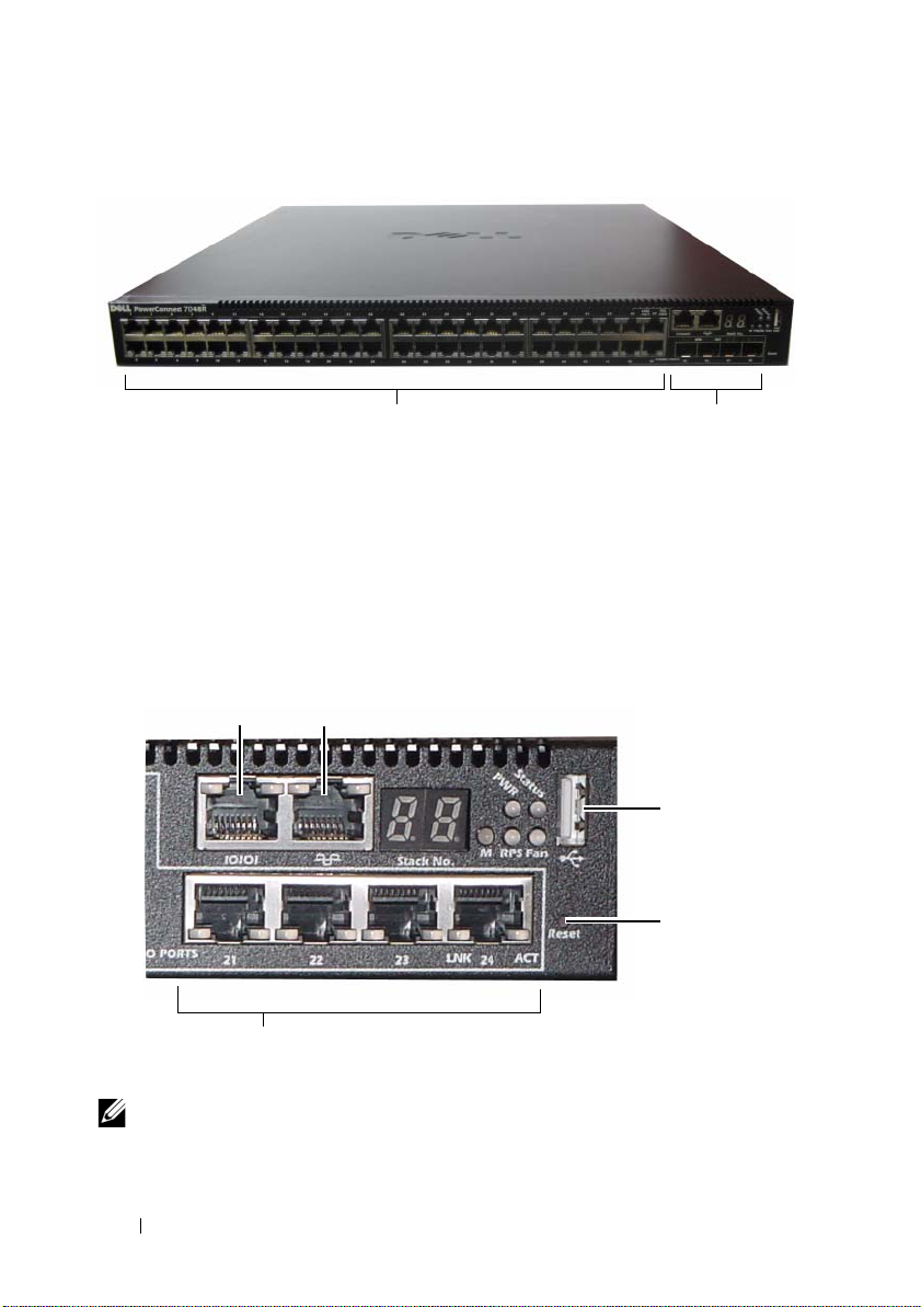
圖 1-6. PowerConnect 7048R,具有 48 個 10/100/1000BASE-T 連接埠
10/100/1000BASE-T 自動感測
全雙工 RJ-45 連接埠
組合連接埠
除了交換器連接埠之外,該系列每種型號的前板還包括以下連接埠:
•
主控臺連接埠
•
帶外管理連接埠
• USB
連接埠
其他連接埠位於前板的右側。
圖 1-7. 其他 PowerConnect 7000 系列連接埠
主控臺連接埠 帶外管理埠
USB 連接埠
重設按鈕
組合連接埠
前板還包含一個針孔狀重設按鈕和幾個狀態
註: 並非所有型號的前板上的連接埠 LED 和系統 LED 都相同。圖 1-7 顯示了
PowerConnect 7024、PowerConnect 7024F 和 PowerConnect 7048 交換器上的 LED。
LED
。
70 入門指南
Page 73

交換器連接埠
PowerConnect 7024 和 PowerConnect 7024P
(10/100/1000 Base-T) RJ-45
路
模式,可自動感測速率、流控制和雙工模式。
PowerConnect 7024P
連接埠,每個連接埠最大能提供
PowerConnect 7024F
連接埠和
SFP
PowerConnect 7048
48
個十億位元乙太網路
合連接埠。
(PoE Plus)
前板交換器連接埠具有以下特性:
•
交換器可自動檢測
•SFP
• RJ-45
4
PowerConnect 7048P
的連接埠,每個連接埠最大能提供
連接埠同時支援
連接埠支援速率為
交換器連接埠是符合
前板提供
個組合連接埠,以支援銅質或
、
PowerConnect 7048P 和 PowerConnect 7048R
埠以及
4 個 SFP
30W
20
個十億位元乙太網路
(10/100/1000BASE-T) RJ-45
交換器連接埠是符合
RJ45
連接埠上絞接纜線和直通纜線之間的差別。
SX
模組和
LX
10/100/1000 Mbps
前板提供
SFP
IEEE 802.3at-2009 (PoE Plus)
的功率。
SFP
30W
模組。
24
個十億位元乙太網
組合埠,這些埠具有自動感測
收發機單獨出售。
(10/100/1000BASE-FX)
介質。
連接埠和四個
IEEE 802.3at-2009
的功率。
的半雙工和全雙工模式。
的
前板提供
SFP
組
主控臺連接埠
主控臺連接埠用於通過序列介面進行管理。可以借助此連接埠直接連接到
RJ-45
到內孔
DB-9
交換器,並可從通過提供的序列纜線連接到此連接埠(
接器)的主控臺終端機來存取
主控臺連接埠支援八個資料位元、一個停止位元、無同位檢查位以及無流控制
的非同步資料。預設序列傳輸速率為
CLI
。
9600 bps。
連
帶外管理連接埠
帶外
(OOB)
交換器管理。此連接埠上的通訊與交換器連接埠上的運行網路通訊是分開的,
並且不能切換或路由到運行網路。
管理連接埠是
10/100/1000BASE-T
乙太網路連接埠,專用于遠端
入門指南 71
Page 74

USB 連接埠
類型 A、內 孔
PowerConnect
您可以使用
間的交換器組態檔和映像。您還可以使用
映像從網路中的一個交換器移動和複製到其他交換器。
USB
連接埠不支援任何其他類型的
USB
連接埠支援
交換器可讀取或寫入格式化為
USB
快閃記憶體磁碟機複製
USB 2.0
USB
相容快閃記憶體磁碟機。
FAT-32
USB
USB
設備。
的快閃記憶體磁碟機。
快閃記憶體磁碟機與交換器之
快閃記憶體磁碟機將組態檔和
重設按鈕
重設按鈕通過針孔進行操作,允許您對交換器進行硬重設。要使用重設按鈕,
請將拗直的迴紋針或類似工具插入針孔。當交換器經重設後完成開機過程時,
會使用最近儲存的組態恢復運行。如 果對正在運行的組態進行了變更,但沒有
在重設之前儲存到啟動組態中,則這些變更都將丟失。
連接埠和系統 LED
前板包含若干個發光二極體
疊和整個系統的狀態。另外,
換器包含的
態和活動的資訊。
有關
組態指南)。
LED
可提供有關連接埠上的
LED
指示的狀態的資訊,請參閱《
(LED)
,用於指示連接埠鏈路、電源設備、風扇、堆
PowerConnect 7024P 和 PowerConnect 7048P
Power over Ethernet Plus (PoE+)
User’s Configuration Guide
》(使用者
交
狀
堆疊主交換器 LED 和堆疊編號顯示
當堆疊內的某個交換器是主單元時,標記為
穩定亮起。如 果
編號)面板顯示堆疊成員的單元編號。如 果交換器不是堆疊的一部分,則
LED
會亮起,並且堆疊單元編號是 1。
M LED
熄滅,則表示該堆疊成員不是主單元。
M
的堆疊主交換器
LED
Stack No.
呈綠色
(堆疊
M
72 入門指南
Page 75

PowerConnect 7000 系列背板
以下影像顯示了
PowerConnect 7000
圖 1-8. PC7024、PC7024F 和 PC7048 背板
風扇通風口
雙 10G 插槽,用於 SFP+、10GBASE-T
或堆疊 /10GbE 模組
圖 1-9. PC7024P 和 PC7048P 背板
風扇通風口
雙 10G 插槽,用於 SFP+、10GBASE-T
或堆疊 /10GbE 模組
系列交換器的背板。
冗餘直流電源設備插座
外部直流電源設備插座
交流電源插座
交流電源插座
圖 1-10. PC7048R 背板
交流電源插座
風扇托架
雙 10G 插槽,用於 SFP+、10GBASE-T
或堆疊 /10GbE 模組
交流電源插座
入門指南 73
Page 76

用於插入式模組的擴充槽
兩個擴充槽位於交換器背面,可支援以下模組:
• 10GBASE-T
•SFP+
•
堆疊
每個插入式模組有兩個連接埠。可以將堆疊
億位元堆疊連接埠或
支援熱交換,因此在安裝好新模組後,無需重新開啟交換器。
模組
/10GbE
模組
模組
/10GbE
10
個十億位元乙太網路交換器連接埠運行。插入式模組
模組組態為作為
電源設備
PC7024 和 PC7024F
PowerConnect 7024 和 PowerConnect 7024F
設備。
附加外部電源設備
提供完全冗餘。
PC7024P
(PowerConnect RPS720) 提供 180
交換器有一個
16
個十
180
瓦的內部電源
瓦電源,為交換器
PowerConnect 7024P
設備
(PowerConnect MPS1000) 提供 1000
PC7048
PowerConnect 7048
設備
(PowerConnect RPS720) 提供 180
PC7048P
PowerConnect 7048P
個
PoE
連接埠。 附加外部電源設備
PoE
連 接 埠,或
74 入門指南
交換器有一個
交換器有一個
交換器有一個
24 個 PoE
連接埠和交換器完全冗餘。
1000
瓦的內部電源設備。 附加外部電源
瓦電源,為交換器提供完全冗餘。
180
瓦的內部電源設備。 附加外部電源
瓦電源,為交換器提供完全冗餘。
1000
瓦的內部電源設備,可支援多達
(PowerConnect MPS1000)
允許所有
24
48 個
Page 77

PC7048R 和 PC7048R-RA
PowerConnect 7048R 和 PowerConnect 7048R-RA
交換器設計為架頂式交
換 器,包 括 兩個用於冗余或均分負載運行的內部可更換交流電源設備。
電源設備可供應
行期間不需要關閉交換器電源即可取出或更換另一個電源設備。
300
瓦電源並支援熱交換。 這意味著在一個電源設備正常運
但是,必須
斷開正在取出或更換的電源設備的電源。
警示: 在拆卸模組之前,請先拔下模組的電源纜線。 插入機箱之前不得接通
電源。
通風系統
PowerConnect 7024、PowerConnect 7024F 和 PowerConnect 7048
扇來實現冷卻。
在內部電源設備中還有第三個風扇。
PowerConnect 7024P 和 PowerConnect 7048P
PowerConnect 7048R
風扇托架,每 個 托架各有一個風扇。
通過三個風
各有兩個風扇,
有兩個可熱交換的
定位 LED
背板上有一個
以從遠端管理系統將
的物理位置。
LED
,可 幫助在滿是交換器的機架或房間內識別 交 換 器。您 可
LED
設為閃爍,以 幫助自己或當地技術人員識別交換器
每個
入門指南 75
Page 78

安裝
現場準備
PowerConnect 7000
機架中,也可單獨放置(在平坦的表面上)並作為獨立式交換器使用。
安裝交換器之前,請確保選擇的安裝位置滿足以下現場要求:
•
電源
—
安裝。
空間
•
•
•
—
連接以及通風的空間。
佈線
—
電線以及螢光照明裝置。
環境溫度
最大相對濕度為
系列交換器可安裝在標準的
交換器應靠近易於插拔的電源插座(
正面和背面有足夠空間供操作員進行操作。留出用於佈線、電源
佈線應遠離電氣噪音干擾源,如無線電發射器、廣播放大器、
—
交換器運行環境溫度範圍為
95%
,非冷凝。
48.26
釐米(
19
英寸)
100-240 VAC,50-60 Hz
0 到 45C(32 到 113F
打開交換器包裝
包裝箱物品
打開每台交換器的包裝時,請 確保其中包含以下物品:
一台
•
•
•
•
•
•
•
•
•
•
PowerConnect
一根交流電源纜線(
一根
RJ-45 到 DB-9
一套用於機架安裝的機架安裝套件( 兩個安裝支架、螺栓和鎖緊螺母)
一套用於獨立式交換器的自粘式橡膠墊(共四個)
使用者說明文件
使用入門指南
安全和管制資訊
保修和支援資訊
軟體許可協定
交換器
PowerConnect 7048R
內孔纜線
CD
帶有兩根交流電源纜線)
)
)之 間,
76 入門指南
Page 79

打開包裝步驟
註: 在打開交換器的包裝之前,先檢查包裝盒,如有任何損壞跡象,請立即
報告。
將包裝盒放在整潔平坦的表面上,然後剪斷固定包裝盒的所有包裝帶。
1
2
打開包裝盒或取下包裝盒蓋。
3
從包裝盒中小心取出交換器,然後將其放在穩固整潔的表面上。
4
取出所有包裝材料。
5
檢查產品及附件是否出現損壞。
安裝交換器
警告: 閱讀安全和管制資訊中的安全資訊,以及有關連接到或支援該交換
器的其他交換器的安全資訊。
交流電源連接器位於交換器的背板上。
在機架中安裝
警告: 請勿使用機架安裝套件將交換器懸掛在工作臺或桌面下,或是將其
固定在牆壁上。
警示: 請在繼續操作前先斷開交換器的所有纜線連接。如果交換器下面裝有
自粘墊,請將其全部取下。
警示: 將多個交換器安裝到機架中時,請從底部往上安裝交換器。
將提供的機架安裝支架放在交換器一側,確保交換器上的安裝孔與機架
1
1-11
安裝支架上的安裝孔對齊。圖
說明了支架的安裝位置。
圖 1-11. 固定支架
入門指南 77
Page 80

2
將提供的螺栓插入機架安裝孔,並 使 用 螺絲刀擰緊。
3
對安裝交換器另一側的機架安裝支架重複該過程。
4
將交換器插入
48.26
釐米(
19
英寸)機架,確保交換器上的機架安裝孔
與機架中的安裝孔對齊。
5
使用機架螺栓或帶有墊片的鎖緊螺母和鎖緊螺栓(視您的機架類型
而定)將交換器固定到機架中。先擰緊底部的螺栓,再擰緊頂部的螺栓。
警示: 請確保提供的機架螺栓與機架中的螺紋底孔相吻合。
註: 請確保通風孔沒有堵塞。
作為獨立式交換器安裝
註: 我們強烈建議將交換器安裝在機架中。
如果您不想把交換器安裝在機架中,請將其安裝在平坦的表面上。該表面必須
能夠支撐交換器和交換器纜線的重量。交換器隨附有四個自粘式橡膠墊。
1
將自粘式橡膠墊放在粘到交換器底部標記的各個位置上。
2
將交換器放在平坦的表面上,確保交換器兩側有
13
間,背面有
釐米(5 英寸)的空間,以 便可以正常通風。
5
釐米(2 英寸)的空
以堆疊方式安裝多台交換器
以堆疊方式最多可以安裝
換器,支援多達
576
12 台 PowerConnect PowerConnect 7000
系列交
個前板連接埠。當通過堆疊連接埠將多台交換器連接在一
起時,這些交換器會作為具有較多連接埠的單個單元運行。堆疊會作為一個整
體進行運行和管理。
註: 如果安裝的是交換器堆疊,則在通電及設定之前,需要組裝堆疊並進行
佈線。交換器堆疊首次通電時,將從這些交換器中選出主交換器,這一主交換
器可能位於堆疊中的任何位置。主單元前板上的主 LED 會亮起。
創建交換器堆疊
要以堆疊方式安裝,請使用交換器背板上的堆疊連接埠來連接相鄰的單元。
堆疊模組單獨出售。圖
接的交換器。
1
在堆疊中每台交換器的一個背面擴充槽中安裝一個單獨購買的堆疊
模組。
78 入門指南
1-12
顯示以環形拓撲(這是針對堆疊的建議拓撲)連
Page 81

2
使用一根短的堆疊纜線,將最頂部的交換器的堆疊連接埠與直接位於其
下方的交換器的堆疊連接埠相連。
如果需要,請使用單獨購買的長 (
3
重複此過程,直 至所有設備連接完成。
4
使用剩下的堆疊纜線連接其他空閒連接埠,一端連接頂部的交換器,一
3
米)堆疊纜線連接到交換器。
端連接底部的交換器。
圖 1-12. 連接交換器堆疊
XG1 連接埠 XG2 連接埠
單元 1
單元 2
單元 3
圖
1-12
中的堆疊使用環形拓撲連接,並且在交換器之間具有以下物理連接:
•
單元
1 上的 XG1
•
單元
2 上的 XG1
•
單元
3 上的 XG3
連接埠連接到單元
連接埠連接到單元
連接埠連接到單元
2 上的 XG2
3 上的 XG4
1 上的 XG2
連接埠。
連接埠。
連接埠。
堆疊備用單元
堆疊功能支援備用或後援單元,當堆疊中的主單元出現故障時,備用單元將發
揮主單元的作用。一 旦發現堆疊中的主單元出現故障,備 用 單 元 就會使用當前
的組態初始化控制層面並啟用其他的所有堆疊單元。備用單元會同步備份堆
疊的當前組態。在切換過程中會關閉並打開所有連接埠以避免出現迴圈,同 時
將新的主軟體套用程式置於一致的狀態。
堆疊中預設定了備用單元,但您也可以使用
用 單 元。有 關 詳情,請參閱《
或《
CLI
參考指南》。
User’s Configuration Guide
CLI
選擇其他的堆疊成員作為備
》(使用者組態指南)
入門指南 79
Page 82
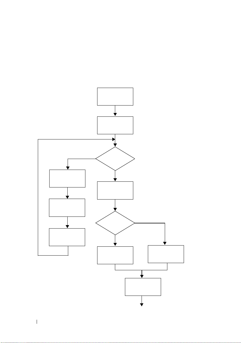
啟動和設定交換器
以下流程圖概述了在打開交換器包裝並安裝好交換器之後,用於進行初始組
態的步驟。
圖 1-13. 安裝和設定流程圖
連接電源和主
控臺
開機
選擇選項 2
開機功能表
(特殊功能)
重新開機
80 入門指南
是
進入開機
菜單?
否
將程式從快閃記
憶體載入到 RAM
進入
精靈?
否
手動初始組態
是
簡易安裝精靈
組態
高級組態
Page 83

將交換器連接至終端機
完成所有外部連接後,將終端機連接至交換器以設定該交換器。
註: 在繼續操作之前,請閱讀本產品的版本注釋。可以從 Dell 支援 Web 站點
support.dell.com/manuals 下載版本注釋。
註: 我們建議您從 Dell 支援 Web 站點 support.dell.com/manuals 獲取最新版本
的使用者說明文件。
要通過序列主控臺監測和設定交換器,請使用交換器前板上的主控臺連接埠
(請參閱圖
模擬軟體的電腦。主控臺連接埠可用作資料終端機設備
要使用主控臺連接埠,需要以下設備:
• VT100
•
要將終端機連接至交換器主控臺連接埠,請執行以下任務:
1
2
3
1-14
),將交換器連接至
相容終端機,或者一台配備序列連接埠並運行
擬軟體
(如 Microsoft HyperTerminal)的臺式機或可式電腦。
一根序列纜線(附帶),帶有連接主控臺連接埠的
端機的
DB-9
連接器。
將序列纜線上的
DB-9
連接器與運行
VT100
終端機或正在運行
(DTE)
RJ-45
VT100
終端機模擬軟體的終端機
VT100
連接器。
VT100
終端機模
連接器和連接終
或電腦相連。
按照以下步驟設定終端機模擬軟體:
a
選擇適當的序列連接埠(例如
b
將資料速率設定為
c
將資料格式設定為
d
將流控制設定為
e
將終端機模擬模式設定為 VT100
f
選擇終端鍵作為功能鍵、箭頭鍵和
鍵(而不是
注: 在 Microsoft Windows 2000 中使用超級終端機時,請確保已安裝
Windows 2000 Service Pack 2 或更高版本。使用 Windows 2000 Service
Pack 2 可以確保箭頭鍵在超級終端機的 VT100 模擬中正常工作。有關
Windows 2000 Service Pack 的詳情,請存取 microsoft.com。
將纜線上的
Microsoft Windows
RJ-45
PowerConnect 7000
符 號,如 圖
注: 如果組態的是交換器堆疊,則將序列纜線連接到主交換器的主控
臺連接埠。如果將終端機連接至附屬交換器,將無法使用 CLI。
1-14
9600
8
個資料位元、1 個停止位以及無同位檢查。
none
(無)。
連接器直接連接到交換器主控臺連接埠。
系列主控臺連接埠位於前板右側,並標有 |O|O|
所示。
波特。
COM 1
。
Ctrl
鍵)。
)連接到主控臺。
鍵。確保此設定適用於終端
終端機
入門指南 81
Page 84
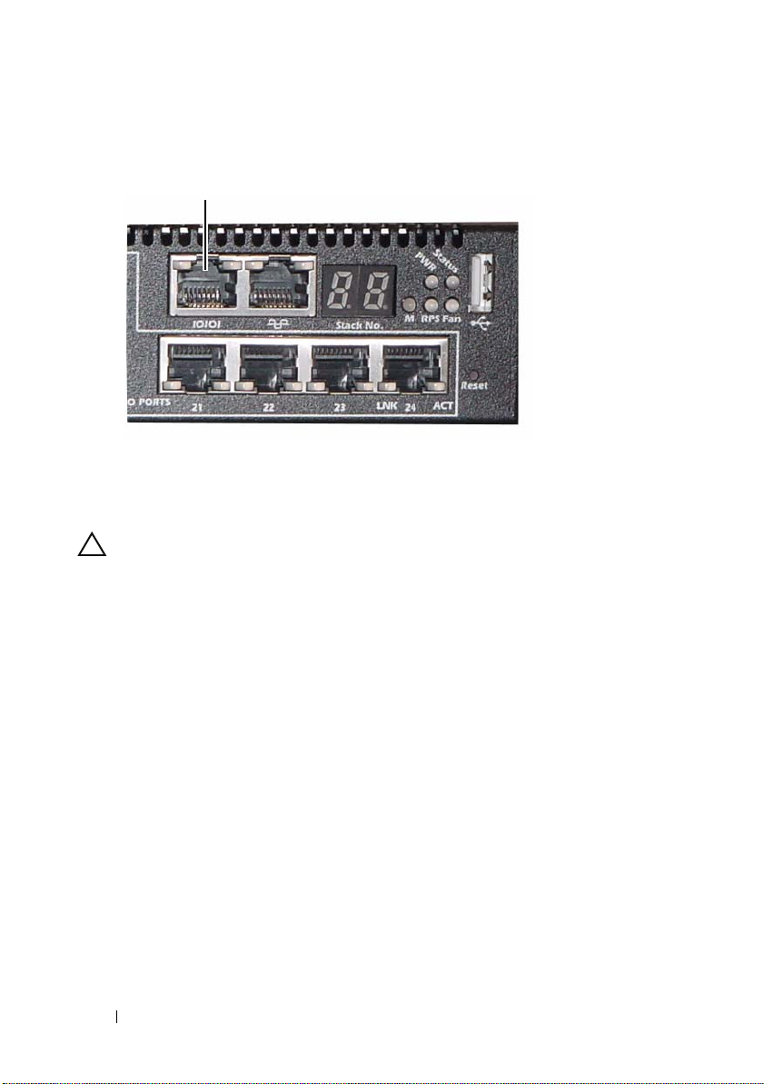
圖 1-14. 主控臺連接埠位置
主控臺連接埠
主控臺連接埠右側的
RJ-45
連接埠用於帶外管理。
將交換器連接到電源設備
警示: 閱讀安全和管制資訊中的安全資訊,以及有關連接到或支援該交換器
的其他交換器的安全資訊。
PowerConnect 7048R
PowerConnect 7000
於背板上。
直流電和交流電連接
1
請確保交換器主控臺連接埠通過
終端機或
2
使用已安全接地的
板上的交流電源主插座(請參閱圖
3
將電源纜線連接至接地的交流電源插座。
4
如果要使用冗餘或外部直流電源設備,例如
PowerConnect MPS1000
插座(請參閱圖
交換器有兩個用於冗余或均分負載運行的電源設備。
系列的所有其他型號都配有一個電源設備。電源插座位
VT100
RJ-45 到 DB-9
終端機模擬程式。
5
英尺(
1.5
米)標準電源纜 線,將 電源纜線連接到背
1-15
)。
內孔纜線連接到
PowerConnect RPS720 或
,則將直流電源線連接到位於背板的直流電源
1-15
)。
VT100
82 入門指南
Page 85
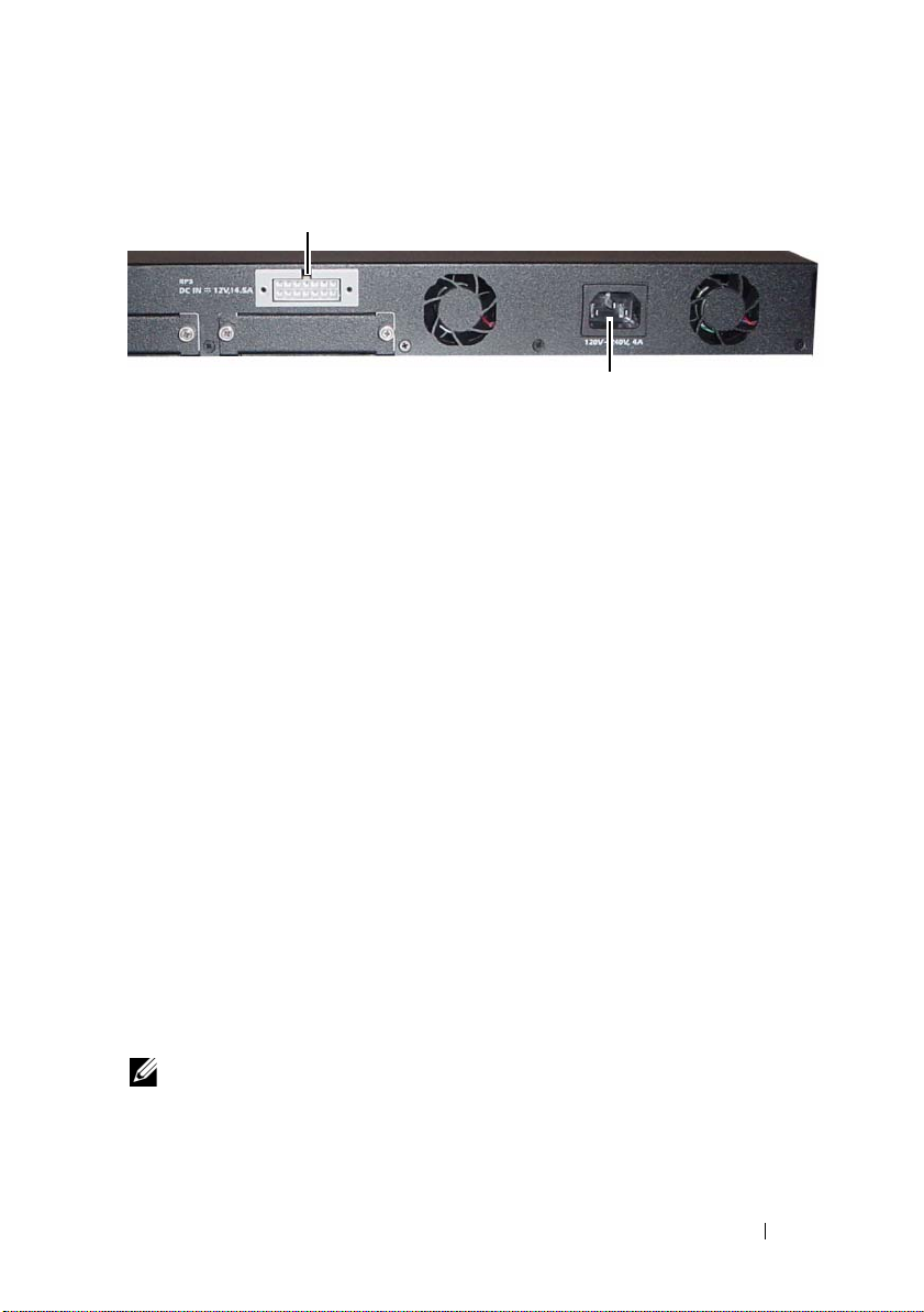
圖 1-15. 交換器的交流和直流電源連接
連接直流電源 (可選)
開啟交換器
連接交流電源
打開電源並連接本機終端機後,交換器將進行開機自測
次初始化交換器時進行,用於檢查硬體元件,以確定交換器在完全開機之前是
POST
否完全正常運轉。如 果
成功 通 過,將 載入一個有效的韌體到
用於指出自測是否成功。開 機 過 程大約運行
POST
在
功能表中,您 可 以 執行組態任務,例如將系統重設為出廠預設值、啟動備份
映像或者恢復密碼。有關
指南》。
第一部分完成後,可以調用
檢測到嚴重問題,程式流就會停止。如果
RAM 中。POST
60
秒。
Boot
(開機)功能表。從
Boot
(開機)功能表功能的詳情,請參閱《
(POST)。POST
資訊顯示在終端機上,
Boot
在每
POST
(開機)
CLI
參考
進行初始組態
初始組態步驟基於以下假設條件:
• PowerConnect
• PowerConnect
•
主控臺連接已建立,並 且
端機或同等終端機設備的螢幕上。
通過主控臺連接埠執行初始交換器組態。完成初始組態後,既可以通過已連接
的主控臺連接埠管理交換器,也可以通過在初始組態過程中定義的介面對交
換器進行遠端管理。
註: 交換器未設定預設的使用者名稱、密碼和 IP 位址。
交換器此前從未進行過任何組態,其狀態與收到時相同。
交換器開機成功。
Dell
簡易安裝精靈提示資訊顯示在
VT100
終
入門指南 83
Page 86

在設定交換器的初始組態之前,從網路管理員處獲得以下資訊:
•
要分配給管理介面 的
•
網路的
IP
•
管理介面預設閘道的
Telnet(Telnet
要通過
需要這些設定。
子網路遮罩。
IP
位址。
IP
位址。
用戶端)或
HTTP(We b
流覽器)來遠端管理交換器,
啟用遠端管理
前板包含用於遠端帶外
埠位於主控臺連接埠右側。另外,可以將前板上的任意交換器連接埠用於帶內
管理。預設情況下,所有帶內連接埠均為
Dell
簡易安裝精靈包括用於為
資訊的提示。對於每種管理介面,都可以分配靜態
用
DHCP
有關用來設定網路資訊的
並允許網路
(OOB)
DHCP
CLI
管理的十億位元乙太網路連接埠。
VLAN 1
OOB
管理介面和
伺服器來分配這些資訊。
命令的 資 訊,請 參 閱《
的成員。
VLAN 1
IP
路由介面設定網路
位址和子網路遮罩,或 啟
CLI
參考指南》。
OOB
連接
初始組態步驟
可以使用
空時,將自動啟動該精靈。可 以 隨時通過輸入
有組態設定都將被丟棄,交換器將使用預設值。
有關使用
南說明如何使用簡易安裝精靈來進行初始交換器組態。該精靈設定交換器的
以下組態:
•
•
•
•
•
•
•
Dell
簡易安裝精靈或
註: 如果不運行簡易安裝精靈或在 60 秒內沒有回應初始簡易安裝精靈提示,
交換器會進入 CLI 模式。
CLI
進行初始組態的詳情,請 參 閱《
建立擁有許可權的初始使用者帳戶以及有效的密碼。在安裝過程中,
該精靈將設定一個具有許可權的使用者帳戶。
啟用
CLI
登入和
HTTP
設定
OOB
管理介面的
設定
VLAN 1
設定
SNMP
換器不使用
允許指定網路管理系統
設定
VLAN 1
路由介面的
管理器在指定
SNMP
介面的預設閘道
CLI
來進行初始組態。當交換器組態檔為
[ctrl+z]
CLI
參考指南》。本 使用入門指
存 取,以 便僅使用本機驗證設定。
IP
位址。
IP
位址,所有帶內連接埠都是該介面的成員。
IP
位址要使用的
管理,則可以選擇跳過這一步。
IP
位址,或允許從所有
IP
位址。
SNMP
IP
退出精靈,但指定的所
團體字串。如 果該交
位址進行管理存取。
84 入門指南
Page 87

示例工作階段
本節介紹了一個簡易安裝精靈工作階段。示例工作階段將使用以下值:
•
要使用的
•
網路管理系統
•
使用者名稱為
• OOB
•VLAN 1
•
預設閘道為
安裝精靈根據上述定義的方式設定初始值。精靈完成後,按照以下方式設定交
換器:
•
啟用
SNMPv3
•
根據定義的方式設定
•
設定網路管理系統。從該管理站,可以存取
通過選擇
介面。
•
在
•
為
•
設定預設閘道位址。
註: 在以下示例中,可能的使用者選項或預設值包括在 [ ] 中。如果未定義選
項,按 <Enter> 鍵將接受預設值。幫助文字在括弧中。
以下示例包含與使用上面列出的輸入值運行
段相關的提示和回應序列。
交換器完成
Unit 1 - Waiting to select management unit)>
SNMP
團體字串為 public
(NMS) IP
admin
管理介面使用 DHCP
路由介面的
10.1.1.1
SNMPv2
,並按上述定義的方式設定團體字串。預 設 情況下,
處於禁用狀態。
(0.0.0.0) IP
OOB
管理介面上啟用
VLAN 1
路由介面設定
POST
並開機後,將顯示以下對話資訊:
。
位址為 10.1.2.100
,密碼為
admin123
來分配
IP
位址為 10.1.1.200
admin
使用者帳戶。
IP
。
。
位址。
,子網路遮罩為 255.255.255.0
SNMP、HTTP 及 CLI
位址,還 可 以 選擇允許所有
DHCP
。
IP
位址。
Dell
介面。
IP
位址存取這些管理
簡易安裝精靈示例工作階
。
Applying Global configuration, please wait ...
Welcome to Dell Easy Setup Wizard
The Setup Wizard guides you through the initial switch
configuration, and gets you up and running as quickly
as possible. You can skip the setup wizard, and enter
CLI mode to manually configure the switch.
入門指南 85
Page 88

You must respond to the next question to run the setup
wizard within 60 seconds, otherwise the system will
continue with normal operation using the default
system configuration. Note: You can exit the setup
wizard at any point by entering [ctrl+z].
Would you like to run the setup wizard (you must
answer this question within 60 seconds)? [Y/N] y
( (單元 1 - 正在等待選擇管理單元) >
正在套用全局組態,請稍候 ...
歡迎使用 Dell 簡易安裝精靈
該安裝精靈將指導您完成初始交換器組態,並儘快使您開機並運行。您可
以跳過安裝精靈,並進入 CLI 模式以手動方式設定交換器。您必須在 60
秒之內答復下一個問題才能運行安裝精靈,否則系統將使用預設的系統組
態繼續正常運行。注:可以隨時通過輸入 [ctrl+z] 鍵退出安裝精靈。
是否要運行安裝精靈 (必須在 60 秒內回答該問題)? [Y/N] y)
Step 1:
The system is not setup for SNMP management by
default. To manage the switch using SNMP (required for
Dell Network Manager) you can
. Set up the initial SNMP version 2 account now.
. Return later and setup other SNMP accounts. (For
more information on setting up an SNMP version 1 or
3 account, see the user documentation).
Would you like to setup the SNMP management interface
now? [Y/N] y
86 入門指南
Page 89

To setup the SNMP management account you must specify
the management system IP address and the "community
string" or password that the particular management
system uses to access the switch. The wizard
automatically assigns the highest access level
[Privilege Level 15] to this account. You can use Dell
Network Manager or other management interfaces to
change this setting, and to add additional management
system information later. For more information on
adding management systems, see the user documentation.
To add a management station:
Please enter the SNMP community string to be used.
[public]: public
注:: 如果已設定,預設存取級別將設定為用於存取 SNMP 管理介面的最高
許可權級別。最初僅啟動 SNMPv2。將禁用 SNMPv3,直至返回而為 SNMPv3
設定安全存取 (例如,引擎 ID,查看等 .
( 步驟 1:
預設情況下,系統未設定為使用 SNMP 管理。要使用 SNMP 管理交換器
(Dell Network Manager 要求),您可以:
. 現在設定初始 SNMP 版本 2 帳戶。
. 稍後返回並設定其他 SNMP 帳戶。(有關設定 SNMP 版本 1 或 3 帳戶的
. 詳情,請參閱使用者說明文件)。
是否立即設定 SNMP 管理介面? [Y/N] y
要設定 SNMP 管理帳戶,必須指定管理系統 IP 位址,以及特定管理系統
用於存取交換器的 「團體字串」或密碼。該精靈將自動為此帳戶分配最
高級別的存取級別 [ 許可權級別 15]。可以使用 Dell Network Manager 或
其他管理介面變更這一設定,並且稍後添加其他管理系統資訊。有關添加
管理系統的詳情,請參閱使用者說明文件。
入門指南 87
Page 90

要添加管理站:
請輸入要使用的 SNMP 團體字串。[public]:public。)
Please enter the IP address of the Management System
(A.B.C.D) or wildcard (0.0.0.0) to manage from any
Management Station. [0.0.0.0]: 10.1.2.100
( 請輸入管理系統的 IP 位址 [A.B.C.D] 或萬用字元 [0.0.0.0] 以便從任何管
理站進行管理。 [0.0.0.0]: 10.1.2.100)
Step 2:
Now we need to setup your initial privilege (Level 15)
user account. This account is used to login to the CLI
and Web interface. You may setup other accounts and
change privilege levels later. For more information on
setting up user accounts and changing privilege
levels, see the user documentation.
To setup a user account:
Please enter the user name. [root]:admin
Please enter the user password: ********
Please reenter the user password: ********
( 步驟 2:
現在,需要設定您的初始許可權 (級別 15)使用者帳戶。該帳戶用於
登入到 CLI 介面及 Web 介面。稍後,可以設定其他帳戶並變更許可權
級別。有關設定使用者帳戶和變更許可權級別的詳情,請參閱使用者說明
文件。
要設定使用者帳戶:
請輸入使用者名稱:[root]:admin
請輸入使用者密碼: ********
請重新輸入使用者密碼: ********)
88 入門指南
Page 91

Step 3:
Next, IP addresses are setup on the OOB (Out-Of-Band)
Interface and/or the VLAN 1 routing interface.
You can use these IP addresses to access the CLI, Web
interface, or SNMP interface of the switch.
To access the switch through any Management Interface
you can
. Setup the IP address for the Management Interface.
. Setup the default gateway if IP address is manually
configured on both routing and OOB interface.
Would you like to setup the Out-Of-Band interface now?
[Y/N] y
Please enter the IP address of the device (A.B.C.D) or
enter "DHCP" (without the quotes) to automatically
request an IP address from the network DHCP server.
[192.168.2.1]: dhcp
( 步驟 3:
接下來,在 OOB (帶外)介面和 / 或 VLAN 1 路由介面上設定 IP 位址。
可以使用這些 IP 位址來存取交換器的 CLI、We b 介面或者 SNMP 介面。
要通過任何管理介面存取交換器,您可以:
. 設定管理介面的 IP 位址。
. 如果同時在路由和 OOB 介面上手動 設定 IP 位址,則設定預設閘道。
是否立即設定帶外介面? [Y/N] y
請輸入設備的 IP 位址 (A.B.C.D) 或輸入 「DHCP」(不帶引號),自動向
網路 DHCP 伺服器請求 IP 位址。[192.168.2.1]: dhcp)
入門指南 89
Page 92

Step 4:
Would you like to setup the VLAN1 routing interface
now? [Y/N] y
Please enter the IP address of the device (A.B.C.D) or
enter "DHCP" (without the quotes) to automatically
request an IP address from the network DHCP server:
10.1.1.200
Please enter the IP subnet mask (A.B.C.D or /nn):
255.255.255.0
( 步驟 4:
是否立即設定 VLAN 1 路由介面? [Y/N] y
請輸入設備的 IP 位址 (A.B.C.D) 或輸入 「DHCP」(不帶引號),自動向
網路 DHCP 伺服器請求 IP 位址: 10.1.1.200
請輸入 IP 子網路遮罩 (A.B.C.D 或 /nn): 255.255.255.0)
Step 5:
Finally, setup the default gateway. Please enter the
IP address of the gateway from which this network is
reachable. [0.0.0.0]: 10.1.1.1
This is the configuration information that has been
collected:
SNMP Interface = "public"@10.1.2.100
User Account setup = admin
Password = ********
Out-of-band IP address = DHCP
VLAN1 Router Interface IP = 10.1.1.200 255.255.255.0
Default Gateway = 10.1.1.1
90 入門指南
Page 93

( 步驟 5:
最後,設定預設閘道。請輸入通過它可存取網路的閘道的 IP 位址。
[0.0.0.0]: 10.1.1.1
以下是已收集的組態資訊:
SNMP 介面 = "public"@10.1.2.100
使用者帳戶設定 = admin
密碼 = ********
帶外 IP 地址 = DHCP
VLAN1 路由器介面 IP = 10.1.1.200 255.255.255.0
預設閘道 = 10.1.1.1)
Step 6:
If the information is correct, please enter (Y) to
save the configuration and copy the settings to the
start-up configuration file. If the information is
incorrect, enter (N) to discard the configuration and
restart the wizard: [Y/N] y
Thank you for using the Dell Easy Setup Wizard.
You will now enter CLI mode.
Applying Interface configuration, please wait ...
( 步驟 6:
如果資訊正確,請輸入 (Y) 儲存組態,並將其複製到啟動組態檔。如果資
訊不正確,請輸入 (N) 丟棄組態,然後重新啟動精靈:[Y/N] y
感謝您使用 Dell 簡易安裝精靈。現在您將進入 CLI 模式。
正在套用介面組態,請稍候 ...)
入門指南 91
Page 94

接下來的步驟
完成本節所述的初始組態後,您可以將
行帶外遠端管理,也可以將任意前板交換器連接埠連接到生產網路以便進行
帶內遠端管理。
OOB 或 VLAN 1
如果為
的
DHCP
伺服器獲得其
管理介面
IP
地址。要發現動態分配的
連接埠連接來發出以下命令:
•
對於
OOB
介面,請輸入 show ip interface out-of-band
•
對於
VLAN 1
要存取
Dell OpenManage Switch Administrator
址欄位中輸入
存取,請在
Telnet 或 SSH
路由介面,請輸入 show ip interface
OOB 或 VLAN 1
用戶端中輸入
或者,可以繼續使用主控臺連接埠對交換器進行本機
PowerConnect 7000
您的
系列交換器支援基本的交換功能(如
樹狀目錄通訊協定),以及高級第
基於
Web
的管理介面或
CLI
可設定您的網路需要的功能。有關如何設定交
換器功能的資訊,請參閱使用者說明文件
》(使用者組態指南)或《
Guide
點獲取:
support.dell.com/manuals
OOB
連接埠連接到管理網路以便進
IP
位址指定了
DHCP
,則介面會從網路上
IP
位址,請使用主控臺
。
。
管理介面
介面,請在
IP
位址。要 對
OOB 或 VLAN 1
CLI
CLI
Web
流覽器的地
進行遠端管理
管理介面
存取。
VLAN
3
層功能(如動態路由和多點傳送)。使用
CD
上的《
User's Configuration
CLI
參考指南》,這 些 資 料 也可從以下支援站
。
IP
位址。
和跨距
PoE 電源預算
提供以下
電源設備類型 /
瓦
僅限 AC 180 瓦 720 瓦 180 瓦 720 瓦
僅限 MPS 180 瓦 720 瓦 180 瓦 720 瓦
AC 和 MPS 180 瓦 720 瓦 180 瓦 1440 瓦
PoE
電源預算資訊以符合法規測試要求。
PowerConnect 7024P PowerConnect 7048P
為非 PoE 系統分
配的電源 (瓦)
為 PoE 系統分配
的電源 (瓦)
為非 PoE 系統分
配的電源 (瓦)
為 PoE 系統分配
的電源 (瓦)
92 入門指南
Page 95

Commutateur Dell
PowerConnect de la série 7000
Guide de mise en route
Modèles réglementaires : PC7024,
PC7024P, PC7024F, PC7048, PC7048P,
PC7048R, et PC7048R-RA
Page 96

Remarques, précautions et avertissements
REMARQUE : Une REMARQUE indique des informations importantes qui peuvent
vous aider à mieux utiliser votre ordinateur.
PRÉCAUTION : Une PRECAUTION indique un risque potentiel d'endommagement
du matériel ou de pertes de données si les instructions ne sont pas suivies.
AVERTISSEMENT : UN AVERTISSEMENT indique un risque potentiel
d'endommagement du matériel, de blessure corporelle ou de mort.
____________________
Les informations contenues dans ce document peuvent être modifiées sans préavis.
© 2011 Dell Inc. tous droits réservés.
La reproduction de ce document de quelque manière que ce soit sans l'autorisation écrite de Dell Inc.
est strictement interdite.
Marques utilisées dans ce document : Dell™, le logo DELL, PowerConnect™ et OpenManage™ sont
des marques de Dell Inc. Microsoft
sont des marques ou des marques déposées de Microsoft Corporation aux États-Unis et/ou dans
d’autres pays.
Tous les autres noms de marques et marques commerciales utilisés dans ce document se rapportent
aux sociétés propriétaires de ces marques et de ces noms ou à leurs produits. Dell Inc. décline tout
intérêt propriétaire vis-à-vis des marques et des noms de marque autres que les siens.
®
, Windows®, Windows Server®, MS-DOS® et Windows Vista®
Modèles réglementaires : PC7024, PC7024P, PC7024F, PC7048, PC7048P, PC7048R, et PC7048R-RA
Mars 2011 N/P D3R71 Rév. A00
Page 97

Table des matières
1 Introduction . . . . . . . . . . . . . . . . . . . . . . . 97
Présentation générale des commutateurs
PowerConnect de la série 7000
2 Présentation du matériel. . . . . . . . . . . . . 98
Panneau avant des PowerConnect de la série 7000 . . 98
Ports de commutateur
Port de console
Port de gestion hors bande
Port USB
. . . . . . . . . . . . . . . . . . . . . . 102
Bouton Reset (Réinitialisation)
Voyants DEL des ports et du système
Voyant maître de la pile et affichage du
numéro de la pile
. . . . . . . . . . . . . . . 101
. . . . . . . . . . . . . . . . . . . 102
. . . . . . . . . . . . . . . . . . 103
. . . . . . . . . . . . . 97
. . . . . . . . . . . . . 102
. . . . . . . . . . . 103
. . . . . . . 103
Panneau arrière des
PowerConnect de la série 7000
. . . . . . . . . . . . . 104
Logements d'extension pour modules plug-in
Blocs d'alimentation
Système de ventilation
Voyant localisateur
. . . . . . . . . . . . . . . . 106
. . . . . . . . . . . . . . . 107
. . . . . . . . . . . . . . . . . 107
. . . 105
Table des matières 95
Page 98

3Installation. . . . . . . . . . . . . . . . . . . . . . . 108
Préparation du site. . . . . . . . . . . . . . . . . . . 108
Déballage du commutateur
Contenu du carton
Etapes du déballage
Montage du commutateur
Montage en rack
. . . . . . . . . . . . . . 109
. . . . . . . . . . . . . . . . 109
. . . . . . . . . . . . . . . 109
. . . . . . . . . . . . . . . 110
. . . . . . . . . . . . . . . . . 110
Installation d'un commutateur autonome
Empilage de plusieurs commutateurs
Création d'une pile de commutateurs
4 Démarrage et configuration
du commutateur
Connexion du commutateur à un terminal . . . . . . 115
Connexion d'un commutateur à un bloc
d'alimentation
Connexion des câbles d'alimentation
en CA et en CC
Démarrage du commutateur
. . . . . . . . . . . . . . . . . . 114
. . . . . . . . . . . . . . . . . . . . . 117
. . . . . . . . . . . . . . . . . . 117
. . . . . . . . . . . . . . 118
. . . . 111
. . . . . . . . . 111
. . . . . . 112
Réalisation de la configuration initiale
Activation de la gestion à distance
Procédure de configuration initiale
Exemple de session
Prochaines étapes
5 Budget de puissance PoE . . . . . . . . . . . 127
96 Table des matières
. . . . . . . . 118
. . . . . . . . 119
. . . . . . . . 119
. . . . . . . . . . . . . . . . 120
. . . . . . . . . . . . . . . . 126
Page 99

Introduction
Ce document contient des informations générales sur les commutateurs
Dell PowerConnect de la série 7000, ainsi que des informations relatives à
l'installation d'un commutateur et de sa configuration initiale. Pour obtenir
des informations sur la configuration et le contrôle des caractéristiques du
commutateur, reportez-vous au User's Configuration Guide (Guide de
configuration), que vous trouverez sur le CD User Documentation
(Documentation utilisateur). Vous pouvez également vous rendre sur le site
Web du support de Dell à l'adresse support.dell.com pour prendre
connaissance des dernières mises à jour concernant la documentation et
le micrologiciel.
Ce document contient les sections suivantes :
• Présentation du matériel
• Installation
• Démarrage et configuration du commutateur
Présentation générale des commutateurs PowerConnect de la série 7000
Les commutateurs PowerConnect de la série 7000 sont des commutateurs
Ethernet Gigabit de couche 3 empilables et comprennent les six modèles
suivants :
• PowerConnect 7024 (PC7024)
• PowerConnect 7024P (PC7024P)
• PowerConnect 7024F (PC7024F)
• PowerConnect 7048 (PC7048)
• PowerConnect 7048P (PC7048P)
• PowerConnect 7048R (PC7048R/PC7048R-RA)
REMARQUE : Le PowerConnect 7048R (PC7048R/PC7048R-RA) est un
commutateur «top-of-rack». La différence entre les modèles PC7048R et
PC7048R-RA est l'orientation de la ventilation.
Guide de mise en route 97
Page 100
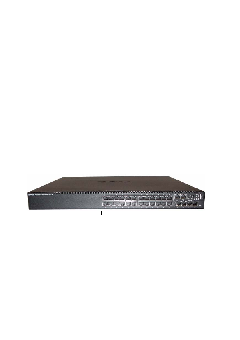
Présentation du matériel
Cette section contient des informations sur les caractéristiques du dispositif
et sur les configurations matérielles des modules des commutateurs
PowerConnect de la série 7000.
Tous les modèles sont des commutateurs 1U montables sur rack avec
les dimensions suivantes :
• 440 x 460 x 44 mm (Largeur x Profondeur x Hauteur)
• 17,3 x 18,1 x 1,74 po (Largeur x Profondeur x Hauteur)
Panneau avant des PowerConnect de la série 7000
Les images suivantes présentent les panneaux avant des six modèles
de commutateurs PowerConnect de la série 7000.
Figure 1-1. PowerConnect 7024 avec 24 ports 10/100/1000 BASE-T
intégral et à détection automatique
98 Guide de mise en route
Ports comboPorts RJ-45 10/100/1000 BASE-T en duplex
 Loading...