

Page 1

Dell™ PowerConnect™ 6200 Series
Configuration Guide
Model: PC6224, PC6248, PC6224P, PC6248P, and PC6224F
www.dell.com | support.dell.com
Page 2

Notes, Cautions, and Warnings
NOTE: A NOTE indicates important information that helps you make better use of your computer.
CAUTION: A CAUTION indicates potential damage to hardware or loss of data if instructions are not followed.
WARNING: A WARNING indicates a potential for property damage, personal injury, or death.
____________________
Information in this document is subject to change without notice.
© 2010 Dell Inc. All rights reserved.
Reproduction of these materials in any manner whatsoever without the written permission of Dell Inc. is strictly forbidden.
Trademarks used in this text: Dell, the DELL logo, and PowerConnect are trademarks of Dell Inc. sFlow is a registered trademark of InMon
Corporation. Cisco is a registered trademark of Cisco Systems, Inc. and/or its affiliates in the United States and certain other countries.
Other trademarks and trade names may be used in this document to refer to either the entities claiming the marks and names or their products.
Dell Inc. disclaims any proprietary interest in trademarks and trade names other than its own.
Model: PC6224, PC6248, PC6224P, PC6248P, and PC6224F
April 2010 Rev. A04
Page 3

Contents
1 About this Document . . . . . . . . . . . . . . . . . . . . . . . . . . . 9
Organization . . . . . . . . . . . . . . . . . . . . . . . . . . . . . . . . . . . . 9
Additional Documentation . . . . . . . . . . . . . . . . . . . . . . . . . . . . 10
2 System Configuration. . . . . . . . . . . . . . . . . . . . . . . . . . . 11
Traceroute . . . . . . . . . . . . . . . . . . . . . . . . . . . . . . . . . . . . 12
CLI Example . . . . . . . . . . . . . . . . . . . . . . . . . . . . . . . . . 12
Configuration Scripting
. . . . . . . . . . . . . . . . . . . . . . . . . . . . . 13
Overview . . . . . . . . . . . . . . . . . . . . . . . . . . . . . . . . . . 13
Considerations . . . . . . . . . . . . . . . . . . . . . . . . . . . . . . . 13
CLI Examples . . . . . . . . . . . . . . . . . . . . . . . . . . . . . . . . 14
Outbound Telnet . . . . . . . . . . . . . . . . . . . . . . . . . . . . . . . . . 16
Overview
CLI Examples
Simple Network Time Protocol (SNTP)
. . . . . . . . . . . . . . . . . . . . . . . . . . . . . . . . . . 16
. . . . . . . . . . . . . . . . . . . . . . . . . . . . . . . . 17
. . . . . . . . . . . . . . . . . . . . . 17
Overview . . . . . . . . . . . . . . . . . . . . . . . . . . . . . . . . . . 17
CLI Examples . . . . . . . . . . . . . . . . . . . . . . . . . . . . . . . . 18
. . . . . . . . . . . . . . . . . . . . . . . . . . . . . . . . . . . . . . 20
Syslog
Overview . . . . . . . . . . . . . . . . . . . . . . . . . . . . . . . . . . 20
CLI Examples
Port Description
CLI Example
Storm Control
CLI Example
Cable Diagnostics
Copper Port Cable Test
Fiber Port Cable Test
. . . . . . . . . . . . . . . . . . . . . . . . . . . . . . . . 20
. . . . . . . . . . . . . . . . . . . . . . . . . . . . . . . . . 22
. . . . . . . . . . . . . . . . . . . . . . . . . . . . . . . . . 22
. . . . . . . . . . . . . . . . . . . . . . . . . . . . . . . . . . . 23
. . . . . . . . . . . . . . . . . . . . . . . . . . . . . . . . . 23
. . . . . . . . . . . . . . . . . . . . . . . . . . . . . . . . 25
. . . . . . . . . . . . . . . . . . . . . . . . . . . 25
. . . . . . . . . . . . . . . . . . . . . . . . . . . . 27
3
Page 4

3 Switching Configuration. . . . . . . . . . . . . . . . . . . . . . . . . 29
Virtual LANs . . . . . . . . . . . . . . . . . . . . . . . . . . . . . . . . . . . 29
VLAN Configuration Example . . . . . . . . . . . . . . . . . . . . . . . . 30
CLI Examples . . . . . . . . . . . . . . . . . . . . . . . . . . . . . . . . 31
Web Interface
IP Subnet and MAC-Based VLANs . . . . . . . . . . . . . . . . . . . . . 34
CLI Examples . . . . . . . . . . . . . . . . . . . . . . . . . . . . . . . . 34
Private Edge VLANs
CLI Example . . . . . . . . . . . . . . . . . . . . . . . . . . . . . . . . . 36
. . . . . . . . . . . . . . . . . . . . . . . . . . . . . . . . 33
. . . . . . . . . . . . . . . . . . . . . . . . . . . . . 35
Voice VLAN
. . . . . . . . . . . . . . . . . . . . . . . . . . . . . . . . . . . . 37
Using Voice VLAN. . . . . . . . . . . . . . . . . . . . . . . . . . . . . . 37
Interaction with LLDP-MED. . . . . . . . . . . . . . . . . . . . . . . . . 38
IGMP Snooping. . . . . . . . . . . . . . . . . . . . . . . . . . . . . . . . . . 40
CLI Examples
. . . . . . . . . . . . . . . . . . . . . . . . . . . . . . . . 40
IGMP Snooping Querier . . . . . . . . . . . . . . . . . . . . . . . . . . . . . 43
CLI Examples
. . . . . . . . . . . . . . . . . . . . . . . . . . . . . . . . 43
Link Aggregation/Port Channels. . . . . . . . . . . . . . . . . . . . . . . . . 45
CLI Example
Web Interface Configuration: LAGs/Port-channels
Port Mirroring
. . . . . . . . . . . . . . . . . . . . . . . . . . . . . . . . . 46
. . . . . . . . . . . . 48
. . . . . . . . . . . . . . . . . . . . . . . . . . . . . . . . . . 49
Overview . . . . . . . . . . . . . . . . . . . . . . . . . . . . . . . . . . 49
CLI Examples . . . . . . . . . . . . . . . . . . . . . . . . . . . . . . . . 49
Port Security
. . . . . . . . . . . . . . . . . . . . . . . . . . . . . . . . . . . 50
Overview . . . . . . . . . . . . . . . . . . . . . . . . . . . . . . . . . . 50
Operation
CLI Examples
Link Layer Discovery Protocol
CLI Examples
. . . . . . . . . . . . . . . . . . . . . . . . . . . . . . . . . . 50
. . . . . . . . . . . . . . . . . . . . . . . . . . . . . . . . 51
. . . . . . . . . . . . . . . . . . . . . . . . . . 52
. . . . . . . . . . . . . . . . . . . . . . . . . . . . . . . . 52
Denial of Service Attack Protection
Overview
CLI Examples
DHCP Snooping
. . . . . . . . . . . . . . . . . . . . . . . . . . . . . . . . . . 54
. . . . . . . . . . . . . . . . . . . . . . . . . . . . . . . . 55
. . . . . . . . . . . . . . . . . . . . . . . . . . . . . . . . . 56
. . . . . . . . . . . . . . . . . . . . . . . 54
CLI Examples . . . . . . . . . . . . . . . . . . . . . . . . . . . . . . . . 59
4
Page 5

sFlow . . . . . . . . . . . . . . . . . . . . . . . . . . . . . . . . . . . . . . . 67
Overview . . . . . . . . . . . . . . . . . . . . . . . . . . . . . . . . . . 67
sFlow Agents . . . . . . . . . . . . . . . . . . . . . . . . . . . . . . . . 68
CLI Examples . . . . . . . . . . . . . . . . . . . . . . . . . . . . . . . . 69
4 Routing Configuration . . . . . . . . . . . . . . . . . . . . . . . . . . 73
VLAN Routing. . . . . . . . . . . . . . . . . . . . . . . . . . . . . . . . . . . 74
CLI Examples
Using the Web Interface to Configure VLAN Routing
. . . . . . . . . . . . . . . . . . . . . . . . . . . . . . . . 74
. . . . . . . . . . . 76
Virtual Router Redundancy Protocol
. . . . . . . . . . . . . . . . . . . . . . 77
CLI Examples . . . . . . . . . . . . . . . . . . . . . . . . . . . . . . . . 77
Using the Web Interface to Configure VRRP . . . . . . . . . . . . . . . . 79
Proxy Address Resolution Protocol (ARP)
. . . . . . . . . . . . . . . . . . . . 80
Overview . . . . . . . . . . . . . . . . . . . . . . . . . . . . . . . . . . 80
CLI Examples . . . . . . . . . . . . . . . . . . . . . . . . . . . . . . . . 80
OSPF . . . . . . . . . . . . . . . . . . . . . . . . . . . . . . . . . . . . . . . 81
OSPF Concepts and Terms
CLI Examples
. . . . . . . . . . . . . . . . . . . . . . . . . . . . . . . . 83
Routing Information Protocol
. . . . . . . . . . . . . . . . . . . . . . . . . 81
. . . . . . . . . . . . . . . . . . . . . . . . . . 92
RIP Configuration . . . . . . . . . . . . . . . . . . . . . . . . . . . . . . 92
CLI Examples . . . . . . . . . . . . . . . . . . . . . . . . . . . . . . . . 93
Using the Web Interface to Configure RIP . . . . . . . . . . . . . . . . . 94
Route Preferences . . . . . . . . . . . . . . . . . . . . . . . . . . . . . . . . 95
Assigning Administrative Preferences to Routing Protocols
Using Equal Cost Multipath
Loopback Interfaces
IP Helper
. . . . . . . . . . . . . . . . . . . . . . . . . . . . . . . . . . . . 100
. . . . . . . . . . . . . . . . . . . . . . . . . . . . . . . 99
. . . . . . . . . . . . . . . . . . . . . . . . . 97
. . . . . . . . 95
CLI Examples . . . . . . . . . . . . . . . . . . . . . . . . . . . . . . . 102
5
Page 6

5 Device Security. . . . . . . . . . . . . . . . . . . . . . . . . . . . . . 105
802.1x Network Access Control . . . . . . . . . . . . . . . . . . . . . . . . 106
802.1x Network Access Control Examples . . . . . . . . . . . . . . . . 106
802.1X Authentication and VLANs
. . . . . . . . . . . . . . . . . . . . . . . 109
Authenticated and Unauthenticated VLANs . . . . . . . . . . . . . . . 109
Guest VLAN . . . . . . . . . . . . . . . . . . . . . . . . . . . . . . . . 109
CLI Examples
Authentication Server Filter Assignment
Access Control Lists (ACLs)
. . . . . . . . . . . . . . . . . . . . . . . . . . . . . . . 110
. . . . . . . . . . . . . . . . . . . 111
. . . . . . . . . . . . . . . . . . . . . . . . . . 111
Overview . . . . . . . . . . . . . . . . . . . . . . . . . . . . . . . . . 111
MAC ACLs. . . . . . . . . . . . . . . . . . . . . . . . . . . . . . . . . 113
IP ACLs
. . . . . . . . . . . . . . . . . . . . . . . . . . . . . . . . . . 114
ACL Configuration Process . . . . . . . . . . . . . . . . . . . . . . . . 114
IP ACL CLI Example . . . . . . . . . . . . . . . . . . . . . . . . . . . . 115
Configuring a MAC ACL
RADIUS
. . . . . . . . . . . . . . . . . . . . . . . . . . . . . . . . . . . . . 117
. . . . . . . . . . . . . . . . . . . . . . . . . . 116
RADIUS Configuration Examples . . . . . . . . . . . . . . . . . . . . . 118
TAC ACS+
. . . . . . . . . . . . . . . . . . . . . . . . . . . . . . . . . . . . 120
TACACS+ Configuration Example. . . . . . . . . . . . . . . . . . . . . 120
802.1x MAC Authentication Bypass (MAB)
. . . . . . . . . . . . . . . . . . 122
Operation in the Network . . . . . . . . . . . . . . . . . . . . . . . . . 122
CLI Examples . . . . . . . . . . . . . . . . . . . . . . . . . . . . . . . 123
Captive Portal
Overview
. . . . . . . . . . . . . . . . . . . . . . . . . . . . . . . . . 125
. . . . . . . . . . . . . . . . . . . . . . . . . . . . . . . . . 125
Functional Description . . . . . . . . . . . . . . . . . . . . . . . . . . 125
Captive Portal Configuration, Status and Statistics
Captive Portal Status
. . . . . . . . . . . . . . . . . . . . . . . . . . . 128
. . . . . . . . . . . 126
Captive Portal Statistics . . . . . . . . . . . . . . . . . . . . . . . . . 129
CLI Examples
. . . . . . . . . . . . . . . . . . . . . . . . . . . . . . . 129
6
Page 7

6IPv6 . . . . . . . . . . . . . . . . . . . . . . . . . . . . . . . . . . . . . . 135
Overview . . . . . . . . . . . . . . . . . . . . . . . . . . . . . . . . . . . . 135
Interface Configuration . . . . . . . . . . . . . . . . . . . . . . . . . . . . 135
CLI Example
. . . . . . . . . . . . . . . . . . . . . . . . . . . . . . . . 136
7 Quality of Service . . . . . . . . . . . . . . . . . . . . . . . . . . . . 139
Class of Service Queuing . . . . . . . . . . . . . . . . . . . . . . . . . . . 139
Ingress Port Configuration
Egress Port Configuration—Traffic Shaping
Queue configuration . . . . . . . . . . . . . . . . . . . . . . . . . . . 140
Queue Management Type . . . . . . . . . . . . . . . . . . . . . . . . 140
CLI Examples
. . . . . . . . . . . . . . . . . . . . . . . . . . . . . . . 140
. . . . . . . . . . . . . . . . . . . . . . . . 139
. . . . . . . . . . . . . . . 140
Differentiated Services
. . . . . . . . . . . . . . . . . . . . . . . . . . . . 143
CLI Example . . . . . . . . . . . . . . . . . . . . . . . . . . . . . . . . 144
DiffServ for VoIP Configuration Example . . . . . . . . . . . . . . . . . 146
8 Multicast . . . . . . . . . . . . . . . . . . . . . . . . . . . . . . . . . . 149
Overview . . . . . . . . . . . . . . . . . . . . . . . . . . . . . . . . . . . . 149
When to Enable IP Multicast on the PowerConnect 6200 Series Switch 150
IGMP Configuration
CLI Example . . . . . . . . . . . . . . . . . . . . . . . . . . . . . . . . 150
IGMP Proxy
CLI Examples
DVMRP
. . . . . . . . . . . . . . . . . . . . . . . . . . . . . . . . . . . . . 152
CLI Example . . . . . . . . . . . . . . . . . . . . . . . . . . . . . . . . 153
. . . . . . . . . . . . . . . . . . . . . . . . . . . . . . . . . . . . . . . 154
PIM
PIM-SM . . . . . . . . . . . . . . . . . . . . . . . . . . . . . . . . . . 154
PIM-DM . . . . . . . . . . . . . . . . . . . . . . . . . . . . . . . . . . 155
Multicast Routing and IGMP Snooping
. . . . . . . . . . . . . . . . . . . . . . . . . . . . . . 150
. . . . . . . . . . . . . . . . . . . . . . . . . . . . . . . . . . . 151
. . . . . . . . . . . . . . . . . . . . . . . . . . . . . . . 151
. . . . . . . . . . . . . . . . . . . . 157
7
Page 8

9 Utility . . . . . . . . . . . . . . . . . . . . . . . . . . . . . . . . . . . . . 161
Auto Config . . . . . . . . . . . . . . . . . . . . . . . . . . . . . . . . . . . 162
Overview . . . . . . . . . . . . . . . . . . . . . . . . . . . . . . . . . 162
Functional Description . . . . . . . . . . . . . . . . . . . . . . . . . . 162
CLI Examples
. . . . . . . . . . . . . . . . . . . . . . . . . . . . . . . 167
Nonstop Forwarding on a Switch Stack
. . . . . . . . . . . . . . . . . . . . 168
Initiating a Failover . . . . . . . . . . . . . . . . . . . . . . . . . . . . 168
Checkpointing. . . . . . . . . . . . . . . . . . . . . . . . . . . . . . . 168
Switch Stack MAC Addressing and Stack Design Considerations
NSF Network Design Considerations
. . . . . . . . . . . . . . . . . . . 170
NSF Default Behavior. . . . . . . . . . . . . . . . . . . . . . . . . . . 170
Configuration Examples. . . . . . . . . . . . . . . . . . . . . . . . . . 171
. . . 170
8
Page 9

About this Document
This configuration guide provides examples of how to use the Dell™PowerConnect™ 6200 Series
switch in a typical network. It describes the advantages of specific functions the PowerConnect 6200
Series switch provides and includes information about configuring those functions using the
command line interface (CLI).
Organization
This document is organized as follows:
• "System Configuration" on page 11 describes how to configure basic system and port settings, use
system interfaces and utilities, and create and use CLI scripts.
• "Switching Configuration" on page 29 provides configuration scenarios for layer 2 switching,
including creating virtual local area networks (VLANs) and Internet Group Management Protocol
(IGMP) snooping interfaces, and enabling port security.
• "Routing Configuration" on page 73 provides configuration scenarios for layer 3 features such as
VLAN routing, Open Shortest Path First (OSPF), and Routing Information Protocol (RIP).
• "Device Security" on page 105 provides information on creating access control lists and
configuring RADIUS and TACACS+ servers.
• "IPv6" on page 135 describes configuring and using IPv6-enabled interfaces in a mixed IPv6/IPv4
network.
• "Quality of Service" on page 139 provides configuration scenarios for class-of-service (CoS)
queueing and differentiated services (DiffServ).
• "Multicast" on page 149 describes how to configure IGMP, IGMP proxy, Distance Vector Multicast
Routing Protocol (DVMRP), and Protocol Independent Multicast (PIM) on the switch.
• "Utility" on page 161 describes the Auto Config and Nonstop Forwarding (NSF) features.
1
About this Document 9
Page 10

Additional Documentation
The following documentation provides additional information about PowerConnect 6200 Series
software:
•The
•The
•The
• Release notes for your Dell PowerConnect product detail the platform-specific functionality of the
CLI Command Reference
from the command-line interface (CLI) for managing, monitoring, and configuring the switch.
User’s Guide
described in this document can be fully configured using the Web interface. This guide also provides
initial system setup and configuration instructions.
for your Dell PowerConnect switch describes the Web GUI. Many of the scenarios
Getting Started Guide
configure, and operate the system.
software packages, including issues and workarounds.
for your Dell PowerConnect switch describes the commands available
for your Dell PowerConnect switch provides basic information to install,
10 About this Document
Page 11

System Configuration
This section provides configuration scenarios for the following features:
•"Traceroute" on page 12
• "Configuration Scripting" on page 13
• "Outbound Telnet" on page 16
• "Simple Network Time Protocol (SNTP)" on page 17
• "Syslog" on page 20
• "Port Description" on page 22
• "Storm Control" on page 23
• "Cable Diagnostics" on page 25
2
NOTE: For information on setting up the hardware and serial or TFTP connection, refer to the
for your system.
Guide
Getting Started
System Configuration 11
Page 12

Traceroute
Use Traceroute to discover the routes that packets take when traveling on a hop-by-hop basis to their
destination through the network.
• Maps network routes by sending packets with small Time-to-Live (TTL) values and watches the ICMP
time-out announcements
• Command displays all L3 devices
• Can be used to detect issues on the network
• Tracks up to 30 hops
• Default UDP port uses 33434 unless modified in the traceroute command
CLI Example
The following shows an example of using the traceroute command to determine how many hops there
are to the destination. The command output shows each IP address the packet passes through and how
long it takes to get there. In this example, the packet takes 16 hops to reach its destination.
console#traceroute ?
ip Enter IP Address.
ipv6 Use keyword 'ipv6' if entering IPv6 Address.
console#traceroute 72.14.253.99
Traceroute to 72.14.253.99 ,30 hops max 0 byte packets:
1 10.131.10.1 <10 ms <10 ms <10 ms
2 210.210.108.193 <10 ms 10 ms <10 ms
3 192.168.81.1 <10 ms 10 ms <10 ms
4 210.214.5.161 <10 ms 10 ms 10 ms
5 210.214.5.169 <10 ms <10 ms 10 ms
6 124.7.202.2 10 ms <10 ms <10 ms
7 210.18.7.166 40 ms 30 ms 30 ms
8 202.144.2.193 30 ms 30 ms 30 ms
9 202.144.113.151 30 ms 40 ms 30 ms
10 72.14.196.97 40 ms 30 ms 100 ms
11 216.239.43.216 40 ms 40 ms 30 ms
12 216.239.43.209 60 ms 40 ms 40 ms
13 216.239.43.222 40 ms 50 ms 50 ms
14 216.239.43.221 100 ms 110 ms 100 ms
15 209.85.250.88 130 ms 130 ms 120 ms
16 209.85.250.105 130 ms 120 ms 130 ms
17 209.85.250.91 160 ms 160 ms 160 ms
18 216.239.47.237 290 ms 240 ms 250 ms
19 216.239.46.211 240 ms 270 ms 250 ms
12 System Configuration
Page 13

--More-- or (q)uit
20 64.233.174.99 250 ms 240 ms 250 ms
Hop Count = 20 Last TTL = 30 Test attempt = 90 Test Success = 90
Configuration Scripting
Configuration scripting allows you to generate a text-formatted script file that shows the current system
configuration. You can generate multiple scripts and upload and apply them to more than one switch.
Overview
Configuration scripting:
• Provides scripts that can be uploaded from and downloaded to the system.
• Provides flexibility to create command configuration scripts.
• Can be applied to several switches.
• Can save up to ten scripts up to a maximum size of 2 MB of memory.
• Provides List, Delete, Apply, Upload, Download.
• Provides script format of one CLI command per line.
NOTE: The startup-config and backup-config scripts are not bound by the 2 MB memory limit.
Considerations
When you use configuration scripting, keep the following considerations in mind:
• The total number of scripts stored on the system is limited by NVRAM/FLASH size.
• The application of scripts is partial if the script fails. For example, if the script executes five of ten
commands and the script fails, the script stops at five.
• Scripts cannot be modified or deleted while being applied.
• Validation of scripts checks for syntax errors only. It does not validate that the script will run.
System Configuration 13
Page 14

CLI Examples
The following are examples of the commands used for configurations scripting.
Example #1: Viewing the Script Options
console#script ?
apply Applies configuration script to the switch.
delete Deletes a configuration script file from the switch.
list Lists all configuration script files present on the switch.
show Displays the contents of configuration script.
validate Validate the commands of configuration script.
Example #2: Viewing and Deleting Existing Scripts
console#script list
Configuration Script Name Size(Bytes)
-------------------------------- ----------abc.scr 360
running-config 360
startup-config 796
test.scr 360
4 configuration script(s) found.
2046 Kbytes free.
console#script delete test.scr
Are you sure you want to delete the configuration script(s)? (y/n)y
1 configuration script(s) deleted.
Example #3: Applying a Script to the Active Configuration
console#script apply abc.scr
Are you sure you want to apply the configuration script? (y/n)y
.....
....
Configuration script 'abc.scr' applied.
14 System Configuration
Page 15

Example #4: Copying the Active Configuration into a Script
Use this command to capture the running configuration into a script.
console#show running-config running-config.scr
Config script created successfully.
Example #5: Uploading a Configuration Script to the TFTP Server
Use this command to upload a configuration script to the TFTP server.
console#copy script abc.scr tftp://10.27.64.141/abc.scr
Mode........................................... TFTP
Set TFTP Server IP............................. 10.27.64.141
TFTP Path...................................... ./
TFTP Filename.................................. abc.scr
Data Type...................................... Config Script
Source Filename................................ abc.scr
Management access will be blocked for the duration of the transfer
Are you sure you want to start? (y/n) y
267 bytes transferred
File transfer operation completed successfully.
Example #6: Downloading a Configuration Script to the TFTP Server
Use this command to download a configuration script from the TFTP server to the switch.
console#copy tftp://10.27.64.141/abc.scr script abc.scr
Mode........................................... TFTP
Set TFTP Server IP............................. 10.27.64.141
TFTP Path...................................... ./
TFTP Filename.................................. abc.scr
Data Type...................................... Config Script
Destination Filename........................... abc.scr
Management access will be blocked for the duration of the transfer
Are you sure you want to start? (y/n) y
193 bytes transferred
Validating configuration script...
configure
System Configuration 15
Page 16

exit
configure
logging web-session
bridge aging-time 100
exit
Configuration script validated.
File transfer operation completed successfully.
Example #7: Validating a Script
console#script validate abc.scr
ip address dhcp
username "admin" password 16d7a4fca7442dda3ad93c9a726597e4 level 15 encrypted
exit
Configuration script 'abc.scr' validated.
console#script apply abc.scr
Are you sure you want to apply the configuration script? (y/n)y
ip address dhcp
username "admin" password 16d7a4fca7442dda3ad93c9a726597e4 level 15 encrypted
exit
Configuration script 'abc.scr' applied.
Outbound Telnet
Overview
Outbound telnet:
• Establishes an outbound telnet connection between a device and a remote host.
• When a telnet connection is initiated, each side of the connection is assumed to originate and
terminate at a “Network Virtual Terminal” (NVT).
• Server and user hosts do not maintain information about the characteristics of each other’s terminals
and terminal handling conventions.
• Must use a valid IP address.
16 System Configuration
Page 17

CLI Examples
The following are examples of the commands used in the outbound telnet feature.
Example #1: Connecting to Another System by Using Telnet
console#telnet 192.168.77.151
Trying 192.168.77.151...
console#
User:admin
Password:
(Dell PC62XX Routing) >enable
Password:
console#show ip interface
Management Interface:
IP Address..................................... 10.27.65.89
Subnet Mask.................................... 255.255.254.0
Default Gateway................................ 10.27.64.1
Burned In MAC Address.......................... 00FF.F2A3.6688
Network Configuration Protocol Current......... DHCP
Management VLAN ID............................. 4086
Routing Interfaces:
Netdir Multi
Interface IP Address IP Mask Bcast CastFwd
---------- --------------- --------------- -------- --------
Simple Network Time Protocol (SNTP)
Overview
The SNTP implementation has the following features:
• Used for synchronizing network resources
•Adaptation of NTP
• Provides synchronized network timestamp
• Can be used in broadcast or unicast mode
• SNTP client implemented over UDP that listens on port 123
System Configuration 17
Page 18

CLI Examples
The following are examples of the commands used in the SNTP feature.
Example #1: Viewing SNTP Options
(Dell PC62XX Routing)(Config) #sntp ?
console(config)#sntp ?
authenticate Require authentication for received Network Time
Protocol (NTP) traffic from servers.
authentication-key
broadcast Configure SNTP client broadcast parameters.
client Configure the SNTP client parameters.
server Configure SNTP server parameters.
trusted-key Authenticate the identity of a system to which
unicast Configure SNTP client unicast parameters.
Example #2: Configuring the SNTP Server
console(config)#sntp server ?
<ipaddress/domain-name> Enter SNTP server address or the domain name.
console(config)#sntp server 192.168.10.25 ?
Define an authentication key for Simple Network
Protocol (SNTP).
SNTP will synchronize.
Time
key Authentication key to use when sending packets to
this peer.
poll Enable/Disable SNTP server polling.
priority Configure SNTP server priority.
<cr> Press enter to execute the command.
console(config)#sntp server 192.168.10.25
18 System Configuration
Page 19

Example #3: Viewing SNTP Information
console#show sntp ?
configuration Show the configuration of the Simple Network Time
Protocol (SNTP).
status To show the status of the Simple Network Time
Protocol (SNTP).
console#show sntp configuration
Polling interval: 64 seconds
MD5 Authentication keys:
Authentication is not required for synchronization.
Trusted keys:
No trusted keys.
Unicast clients: Enable
Unicast servers:
Server Key Polling Priority
--------- ----------- ----------- ----------
192.168.0.1 Disabled Enabled 1
console#show sntp status
Unicast servers:
Server Status Last response
--------- ----------- --------------------------
192.168.10.25 Unknown 00:00:00 Jan 1 1970
System Configuration 19
Page 20

Syslog
Overview
Syslog:
• Allows you to store system messages and/or errors.
• Can store to local files on the switch or a remote server running a syslog daemon.
• Provides a method of collecting message logs from many systems.
Interpreting Log Files
Figure 2-1 describes the information that displays in log messages.
<130> JAN 01 00:00:06 0.0.0.0-1 UNKN [0x800023]: bootos.c(386) 4 %% Event (0xaaaaaa
AB
A. Priority
B. Timestamp
C. Stack ID
D. Component Name
E. Thread ID
F. File Name
G. Line Number
H Sequence Number
I. Message
Figure 2-1. Log Files Key
C
DEF GH I
CLI Examples
The following are examples of the commands used in the Syslog feature.
Example #1: Viewing Logging Information
console#show logging
aa)
Logging is enabled
Console Logging: level warning. Console Messages: 230 Dropped.
Buffer Logging: level info. Buffer Messages: 230 Logged.
File Logging: level notActive. File Messages: 0 Dropped.
CLI Command Logging : disabled
20 System Configuration
Page 21

Web Session Logging : disabled
SNMP Set Command Logging : disabled
0 Messages were not logged.
Buffer Log:
<189> JAN 01 03:57:58 10.27.65.86-1 TRAPMGR[216282304]: traputil.c(908) 31 %%
Instance 0 has elected a new STP root: 8000:00ff:f2a3:8888
<189> JAN 01 03:57:58 10.27.65.86-1 TRAPMGR[216282304]: traputil.c(908) 32 %%
Instance 0 has elected a new STP root: 8000:0002:bc00:7e2c
<189> JAN 01 04:04:18 10.27.65.86-1 TRAPMGR[231781808]: traputil.c(908) 33 %% New
Spanning Tree Root: 0, Unit: 1
<189> JAN 01 04:04:18 10.27.65.86-1 TRAPMGR[216282304]: traputil.c(908) 34 %% The
unit 1 elected as the new STP root
Example #2: Viewing the Logging File
console#show logging file
Persistent Logging : disabled
Persistent Log Count : 0
Example #5: Configuring Syslog Server
console(config)#logging ?
buffered Buffered (In-Memory) Logging Configuration.
cli-command CLI Command Logging Configuration.
console Console Logging Configuration.
facility Syslog Facility Configuration.
file Configure logging file parameters.
on Enable logging to all supporting destinations.
snmp SNMP Set Command Logging Configuration.
web-session Web Session Logging Configuration.
<ip-address|hostname> Configure syslog server IP address or Hostname up to
63 characters in length
console(config)#logging 192.168.10.65
console(Config-logging)#?
description Specify syslog server description.
exit To exit from the mode.
level Specify logging level.
port Specify UDP port (default is 514).
console(Config-logging)#level ?
System Configuration 21
Page 22

alert Immediate action needed
critical Critical conditions
debug Debugging messages
emergency System is unusable
error Error conditions
info Informational messages
notice Normal but significant conditions
warning Warning conditions
console(Config-logging)#level critical
Port Description
The Port Description feature lets you specify an alphanumeric interface identifier that can be used for
SNMP network management.
CLI Example
Use the commands shown below for the Port Description feature.
Example #1: Enter a Description for a Port
This example specifies the name “Test” for port 1/g17:
console#configure
console(config)#interface ethernet 1/g17
console(config-if-1/g17)#description Test
console(config-if-1/g17)#exit
console(config)#exit
Example #2: Show the Port Description
console#show interfaces description ethernet 1/g17
Port Description
---- ---------------------------------------------------------1/g17 Test
22 System Configuration
Page 23

Storm Control
A traffic storm occurs when incoming packets flood the LAN resulting in network performance
degradation. The Storm Control feature protects against this condition.
The switch software provides broadcast, multicast, and unicast storm recovery for individual interfaces.
Unicast Storm Control protects against traffic whose MAC addresses are not known by the system.
For broadcast, multicast, and unicast storm control, if the rate of traffic ingressing on an interface
increases beyond the configured threshold for that type, the traffic is dropped.
To configure storm control, you will enable the feature for all interfaces or for individual interfaces, and
you will set the threshold (storm control level) beyond which the broadcast, multicast, or unicast traffic
will be dropped.
Configuring a storm-control level also enables that form of storm-control. Disabling a storm-control level
(using the “no” version of the command) sets the storm-control level back to default value and disables
that form of storm-control. Using the “no” version of the “storm-control” command (not stating a
“level”) disables that form of storm-control but maintains the configured “level” (to be active next time
that form of storm-control is enabled).
NOTE: The actual rate of ingress traffic required to activate storm-control is based on the size of incoming packets
and the hard-coded average packet size of 512 bytes - used to calculate a packet-per-second (pps) rate - as the
forwarding-plane requires pps versus an absolute rate Kbps. For example, if the configured limit is 10%, this is
converted to ~25000 pps, and this pps limit is set in forwarding plane (hardware). You get the approximate desired
output when 512bytes packets are used.
CLI Example
The following examples show how to configure the storm control feature an Ethernet interface. The
interface number is 1/g17.
System Configuration 23
Page 24

Example #1: Set Broadcast Storm Control for an Interface
console#configure
console(config)#interface ethernet 1/g17
console(config-if-1/g17)#storm-control broadcast ?
<cr> Press enter to execute the command.
level Configure storm-control thresholds.
console(config-if-1/g17)#storm-control broadcast level ?
<rate> Enter the storm-control threshold as percent of port
speed. Percent of port speed is converted to
PacketsPerSecond based on 512 byte average packet
size and applied to HW. Refer to documentation for
further details.
console(config-if-1/g17)#storm-control broadcast level 7
Example #2: Set Multicast Storm Control for an Interface
console(config-if-1/g17)#storm-control multicast level 8
Example #3: Set Unicast Storm Control for an Interface
console(config-if-1/g17)#storm-control unicast level 5
24 System Configuration
Page 25

Cable Diagnostics
This section describes:
• "Copper Port Cable Test" on page 25
• "Fiber Port Cable Test" on page 27
NOTE: Cable Diagnostics is supported on SFP/XFP ports but not on the Stacking/CX-4/SFP+/10GbaseT ports.
Copper Port Cable Test
The cable test feature enables you to determine the cable connection status on a selected port. The switch
uses Time Domain Reflectometry (TDR) technology to determine the quality and characteristics of a
copper cable attached to a port.
NOTE: The cable test feature is supported only for copper cable. it is not supported for optical fiber cable.
NOTE: The copper-related commands do not apply to the stacking, 10G BaseT, or CX-4 ports associated with these
plug-in modules.
In privileged exec mode, enter test copper-port tdr unit/port to run the cable test on the
specified port. One of the following statuses are returned:
•
Normal
•
Open
•
Short
Cable Test Failed
•
The command also returns a cable length estimate if this feature is supported by the PHY for the current
link speed. The length is displayed as the estimated length. Note that if the link is down and a cable is
attached to a 10/100 Ethernet adapter, then the cable status may display as Open or Short because some
Ethernet adapters leave unused wire pairs unterminated or grounded. Unknown is displayed if the cable
length could not be determined.
If the port has an active link while the cable test is run, the link can go down for the duration of the test. The
test may take several seconds to run.
To view cable status information for multiple ports, enter show copper-ports tdr. If the cable test
has not been run on a port, the results indicate that the test has not been performed.
: The cable is working correctly.
: The cable is disconnected or there is a faulty connector.
: There is an electrical short in the cable.
: The cable status could not be determined. The cable may in fact be working.
System Configuration 25
Page 26

Example #1: Cable Test for Copper Ports
console#test copper-port tdr 1/g1
Cable Status................................... Short
Cable Length................................... 5m
console#show copper-ports tdr
Port Result Length [meters] Date
------- ------ --------------- --------------------1/g1 Short 9 Jan 01 1970 18:03:23
1/g2 Test has not been performed
1/g3 Test has not been performed
1/g4 Test has not been performed
1/g5 Test has not been performed
--More-- or (q)uit
NOTE: You can also run a cable test using the Web Interface. In the navigation tree, click System > Diagnostics.
Example #2: Show Copper Cable Length
Use the show copper-ports cable-length command in Privileged EXEC mode to display the
estimated copper cable length attached to a port. The following example displays the estimated copper
cable length attached to all ports.
console#show copper-ports cable-length
Port Length [meters]
---- ---------------
1/g1 <50
1/g2 Copper not active
1/g3 110-140
1/g4 Fiber
26 System Configuration
Page 27

Example #3: Show Last Time Domain Reflectometry Tests
Use the show copper-ports tdr command in Privileged EXEC mode to display the last Time Domain
Reflectometry (TDR) tests on specified ports.
The following example displays the last TDR tests on all ports.
console#show copper-ports tdr
Port Result Length [meters] Date
---- -------- --------------- ---------------
1/g1 OK
1/g2 Short 50 13:32:00 23 July 2004
1/g3 Test has not been preformed
1/g4 Open 128 13:32:08 23 July 2004
1/g5 Fiber - -
Fiber Port Cable Test
Example #1: Show Optical Transceiver Diagnostics
Use the show fiber-ports optical-transceiver command in Privileged EXEC mode to display the optical
transceiver diagnostics.
NOTE: The show fiber ports command is only applicable to the SFP combo ports and XFP ports (not the ports on
the SFP+ plug-in module).
The following example displays the optical transceiver diagnostics.
console#show fiber-ports optical-transceiver
Port Temp Voltage Current Output Input TX LOS
Power Power Fault
----------- ------ ------- ------- ------ ----- ----- ---
1/g3 w OK E OK OK OK OK
1/g4 OK OK OK OK OK E OK
1/g1 Copper
Temp - Internally measured transceiver temperature
Voltage - Internally measured supply voltage
Current - Measured TX bias current
Output Power - Measured TX output power in milliWatts
Input Power - Measured RX received power in milliWatts
TX Fault - Transmitter fault
LOS - Loss of signal
System Configuration 27
Page 28

28 System Configuration
Page 29

Switching Configuration
This section provides configuration scenarios for the following features:
• "Virtual LANs" on page 29
• "Voice VLAN" on page 37
• "IGMP Snooping" on page 40
• "IGMP Snooping Querier" on page 43
• "Link Aggregation/Port Channels" on page 45
• "Port Mirroring" on page 49
• "Port Security" on page 50
• "Link Layer Discovery Protocol" on page 52
• "Denial of Service Attack Protection" on page 54
• "DHCP Snooping" on page 56
• "sFlow" on page 67
Virtual LANs
Adding Virtual LAN (VLAN) support to a Layer 2 switch offers some of the benefits of both bridging
and routing. Like a bridge, a VLAN switch forwards traffic based on the Layer 2 header, which is fast.
Like a router, it partitions the network into logical segments, which provides better administration,
security and management of multicast traffic.
A VLAN is a set of end stations and the switch ports that connect them. You can have many reasons
for the logical division, for example, department or project membership. The only physical
requirement is that the end station, and the port to which it is connected, both belong to the same
VLAN.
Each VLAN in a network has an associated VLAN ID, which appears in the IEEE 802.1Q tag in the
Layer 2 header of packets transmitted on a VLAN. An end station may omit the tag, or the VLAN
portion of the tag, in which case the first switch port to receive the packet may either reject it or
insert a tag using its default VLAN ID. A given port may handle traffic for more than one VLAN, but
it can only support one default VLAN ID.
Two features let you define packet filters that the switch uses as the matching criteria to determine if
a particular packet belongs to a particular VLAN.
3
Switching Configuration 29
Page 30
• The IP-subnet Based VLAN feature lets you map IP addresses to VLANs by specifying a source IP
address, network mask, and the desired VLAN ID.
• The MAC-based VLAN feature let packets originating from end stations become part of a VLAN
according to source MAC address. To configure the feature, you specify a source MAC address and a
VLAN ID.
The Private Edge VLAN feature lets you set protection between ports located on the switch. This means
that a protected port cannot forward traffic to another protected port on the same switch.
The feature does not provide protection between ports located on different switches.
For information about authenticated, unauthenticated, and guest VLANs, see "802.1X Authentication
and VLANs" on page 109.
VLAN Configuration Example
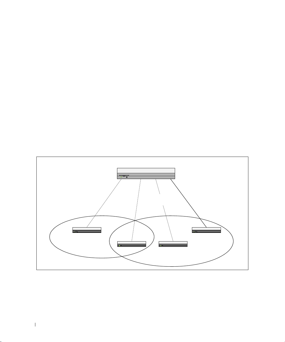
The diagram in this section shows a switch with four ports configured to handle the traffic for two
VLANs. Port 1/g18 handles traffic for both VLANs, while port 1/g17 is a member of VLAN 2 only, and
ports 1/g19 and 1/g20 are members of VLAN 3 only. The script following the diagram shows the
commands you would use to configure the switch as shown in the diagram.
Layer 3 Switch
Port 1/g20
Port 1/g17
Port 1/0/1
VLAN 2
VLAN 2
Port 1/g18
Port 1/0/2
VLANs 2 & 3
VLANs 2 & 3
Port 1/g19
Port 1/0/3
VLAN 3
VLAN 3
Port 1/0/4
VLAN 3
VLAN 3
VLAN 2
Figure 3-1. VLAN Example Network Diagram
30 Switching Configuration
VLAN 3
Page 31

CLI Examples
The following examples show how to create VLANs, assign ports to the VLANs, and assign a VLAN as the
default VLAN to a port.
Example #1: Create Two VLANs
Use the following commands to create two VLANs and to assign the VLAN IDs while leaving the names
blank.
console(config)#vlan database
console(config-vlan)#vlan 2
console(config-vlan)#vlan 3
console(config-vlan)#exit
Example #2: Assign Ports to VLAN2
This sequence shows how to assign ports to VLAN2, specify that frames will always be transmitted
tagged from all member ports, and that untagged frames will be rejected on receipt.
console(config)#interface ethernet 1/g17
console(config-if-1/g17)#switchport mode general
console(config-if-1/g17)#switchport general allowed vlan add 2
console(config-if-1/g17)#
switchport general acceptable-frame-type tagged-
only
console(config-if-1/g17)#exit
console(config)#interface ethernet 1/g18
console(config-if-1/g18)#switchport mode general
console(config-if-1/g18)#switchport general allowed vlan add 2
console(config-if-1/g18)#
switchport general acceptable-frame-type tagged-
only
console(config-if-1/g18)#exit
Switching Configuration 31
Page 32

Example #3: Assign Ports to VLAN3
This example shows how to assign the ports that will belong to VLAN 3. Untagged frames will be
accepted on ports 1/g19 and 1/g20.
Note that port 1/g18 belongs to both VLANs and that port 1/g17 can never belong to VLAN 3.
console(config)#interface ethernet 1/g18
cconsole(config-if-1/g18)#switchport general allowed vlan add 3
console(config-if-1/g18)#exit
console(config)#interface ethernet 1/g19
console(config-if-1/g19)#switchport general allowed vlan add 3
console(config-if-1/g19)#exit
console(config)#interface ethernet 1/g20
console(config-if-1/g20)#switchport general allowed vlan add 3
Example #4: Assign VLAN3 as the Default VLAN
This example shows how to assign VLAN 3 as the default VLAN for port 1/g18.
console(config)#interface ethernet 1/g18
console(config-if-1/g18)#switchport general pvid 3
Example #5: Assign IP Addresses to VLAN 2
In order for the VLAN to function as a routing interface, you must enable routing on the VLAN and on
the switch. Routing is only permitted on VLAN interfaces. Routing on physical interfaces is not
supported.
console#configure
console(config)#interface vlan 2
console(config-if-vlan2)#ip address 192.168.10.33 255.255.255.0
console(config-if-vlan2)#routing
console(config-if-vlan2)#exit
console(config)#ip routing
32 Switching Configuration
Page 33

Example #6: View Information About VLAN 2
console#show ip interface vlan 2
Primary IP Address............................
192.168.10.33/255.255.255.0
Routing Mode.................................. Enable
Administrative Mode........................... Enable
Forward Net Directed Broadcasts............... Disable
Proxy ARP..................................... Enable
Local Proxy ARP............................... Disable
Active State.................................. Inactive
Link Speed Data Rate.......................... 10 Half
MAC Address................................... 00FF.F2A3.888A
Encapsulation Type............................ Ethernet
IP MTU........................................ 1500
Web Interface
Use the following screens to perform the same configuration using the Web Interface:
•
Switching > VLAN > Membership
•
Switching > VLAN > Port Settings.
. To create VLANs and specify port participation.
To specify the PVID and mode for the port.
Switching Configuration 33
Page 34

IP Subnet and MAC-Based VLANs
In addition to port-based VLANs, the switch also supports VLANs that are based on the IP address or
MAC address of a host. With IP subnet and MAC-based VLANs, the VLAN membership is determined
by the address of the host rather than the port to which the host is attached.
CLI Examples
The following examples show how to associate an IP subnet with a VLAN, a specific IP address with a
VLAN, and a MAC address with a VLAN.
Example #1: Associate an IP Subnet with a VLAN
This example shows how to configure the switch so that all hosts with IP addresses in the 192.168.25.0/24
network are members of VLAN 10.
console#configure
console(config)#vlan database
console(config-vlan)#vlan association subnet 192.168.25.0 255.255.255.0
10
Example #2: Associate an IP Address with a VLAN
This example shows how to configure the switch so a host with an IP addresses of 192.168.1.11 is a
member of VLAN 10.
console#configure
console(config)#vlan database
console(config-vlan)#vlan association subnet 192.168.1.11
255.255.255.255 10
Example #3: Associate a MAC Address with a VLAN
This example shows how to configure the switch so a host with a MAC address of 00:ff:f2:a3:88:86 is a
member of VLAN 10.
console#configure
console(config)#vlan database
console(config-vlan)#vlan association mac 00:ff:f2:a3:88:86 10
34 Switching Configuration
Page 35

Example #4: Viewing IP Subnet and MAC-Based VLAN Associations
console#show vlan association mac
MAC Address VLAN ID
----------------- -------
00FF.F2A3.8886 10
console#show vlan association subnet
IP Subnet IP Mask VLAN ID
---------------- ---------------- -------
192.168.25.0 255.255.255.0 10
192.168.1.11 255.255.255.255 10
Private Edge VLANs
Use the Private Edge VLAN feature to prevent ports on the switch from forwarding traffic to each other
even if they are on the same VLAN.
• Protected ports cannot forward traffic to other protected ports in the same group, even if they have the
same VLAN membership. Protected ports can forward traffic to unprotected ports.
• Unprotected ports can forward traffic to both protected and unprotected ports.
You can also configure groups of protected ports, but unprotected ports are independent and cannot be
added to a group. Each group’s configuration consists of a name and a mask of ports. A port can belong
to only one set of protected ports, but an unprotected port can be added to a group as a protected port.
The group name is configurable by the network administrator.
Use the switchport protected command to designate a port as protected. Use the show
switchport protected command to display a listing of the protected ports.
Switching Configuration 35
Page 36

CLI Example
Example #1: Configuring a Protected Port
The commands in this example name the protected port group 1 “PP_Test” and assign ports 1 and 2 to
the group.
console(config)#switchport protected 1 name PP_Test
console(config)#interface ethernet 1/g17
console(config-if-1/g17)#switchport protected 1
console(config-if-1/g17)#exit
console(config)#interface ethernet 1/g18
console(config-if-1/g18)#switchport protected 1
console(config-if-1/g18)#exit
console(config)#exit
Example #2: Viewing Protected Port Group 1
console#show switchport protected 1
Name......................................... "PP_Test"
1/g17, 1/g18
36 Switching Configuration
Page 37

Voice VLAN
Voice VLAN enables switch ports to carry voice traffic with a defined priority in order to enable the
separation of voice and data traffic coming onto the port. A primary benefit of using Voice VLAN is to
ensure that the sound quality of an IP phone is safeguarded from deteriorating when the data traffic on the
port is high.
The inherent isolation provided by VLANs ensures that inter-VLAN traffic is under management control
and that network attached clients cannot initiate a direct attack on voice components. QoS based on IEEE
802.1P class of service (CoS) uses classification and scheduling to send network traffic from the switch in a
predictable manner. The system uses the source MAC address of the traffic traveling through the port to
identify the IP phone data flow.
IP Phones will use this VLAN. They will obtain their VLAN ID via CDP, DHCP or LLDP-MED. The voice
traffic is sent to the switch tagged. The setup protocols (CDP, DHCP, etc.) are not tagged.
Using Voice VLAN
When an IP phone is connected to the switch, the voice traffic from the phone and the data traffic from the
network could potentially deteriorate the voice quality. You can overcome this in multiple ways using
different options in Voice VLAN.
You can configure the switch to support Voice VLAN on a port that is connecting the VOIP phone. Both of
the following methods segregate the voice traffic and the data traffic in order to provide better service to the
voice traffic.
• When a VLAN is associated with the Voice VLAN port, then the VLAN ID information is passed onto
the VOIP phone using the LLDP-MED mechanism. By this method, the voice data coming from the
VOIP phone is tagged with the exchanged VLAN ID, thus regular data arriving on the switch is given
the default PVID of the port, and the voice traffic is received on a pre-defined VLAN. As a result, both
kinds of traffic are segregated in order to provide better service to the voice traffic.
Switching Configuration 37
Page 38

• When a dot1p priority is associated with the Voice VLAN port instead of a VLAN ID, then the priority
information is passed onto the VOIP phone using the LLDP-MED mechanism. By this method, the
voice data coming from the VOIP phone is tagged with VLAN 0 and with the exchanged priority; thus
regular data arriving on the switch is given the default priority of the port (default 0), and the voice
traffic is received with a higher priority.
You can configure the switch to override the data traffic CoS. This feature can override the 802.1 priority of
the data traffic packets arriving at the port enabled for Voice VLAN. Therefore, any rogue client that is also
connected to the Voice VLAN port does not deteriorate the voice traffic.
Interaction with LLDP-MED
The interactions with LLDP-MED are important for Voice VLAN:
• LLDP-MED notifies the Voice VLAN component of the presence and absence of a VoIP phone on the
network.
• The Voice VLAN component interacts with LLDP-MED for applying VLAN ID, priority and tag
information to the VoIP phone traffic.
For release 2.0 and earlier, the Voice VLAN feature can only be used by IP phones that support LLDP-MED,
e.g. 4610SW Avaya phones.
Example#1: Configuring Voice VLAN
The commands in this example create a VLAN for voice traffic with a VLAN ID of 25. Then, Voice VLAN is
administratively enabled on the switch. Finally, port 1/g12 is set to an 802.1Q VLAN and then enabled for
Voice VLAN traffic.
console#configure
console(config)#vlan database
console(config-vlan)#vlan 25
console(config-vlan)#exit
console(config)#voice vlan
console(config)#interface ethernet 1/g12
console(config-if-1/g12)#switchport mode general
console(config-if-1/g12)#voice vlan 25
console(config-if-1/g12)#exit
console(config)#exit
console#show voice vlan interface 1/g12
Interface...................................... 1/g12
Voice VLAN Interface Mode...................... Enabled
Voice VLAN ID.................................. 25
Voice VLAN COS Override........................ False
Voice VLAN Port Status......................... Disabled
Voice VLAN Authentication...................... Enabled
38 Switching Configuration
Page 39

Example #2: Configuring Voice VLAN on an Unauthenticated Port
In some networks, multiple devices (for example, a PC, Printer, and phone) are connected to a single port
on the switch. The PCs and printers are authenticated by 802.1X, but the phone might not support
802.1X authentication. The PowerConnect 6200 Series switches can allow unauthenticated traffic on the
Voice VLAN for the phones that do not support authentication while requiring all other devices on the
port to authenticate individually.
The phones that do not support 802.1X authentication are automatically directed to the Voice VLAN
without manual configuration. The phones will obtain this information using one of the following
methods:
•LLDP-MED
•CDP
•DHCP
In this example, interface 1/g10 is set to an 802.1Q VLAN. The port must be in general mode in order to
enable MAC-based 802.1X authentication. Then, port 1/g10 is configured with MAC-based port
authentication to allow authentication for multiple hosts on the same port (see "Example #2: MACBased Authentication Mode" on page 108 for more information). Next, Voice VLAN is enabled on the
port with the Voice VLAN ID set to 25. Finally, Voice VLAN authentication is disabled on port 1/g10
because the phone connected to that port does not support 802.1X authentication. All other devices are
required to use 802.1X authentication for network access.
Support for unauthenticated Voice VLANs is available in release 2.1 and later versions.
console#configure
console(config)#interface ethernet 1/g10
console(config-if-1/g10)#switchport mode general
console(config-if-1/g10)#dot1x port-control mac-based
console(config-if-1/g10)#voice vlan 25
console(config-if-1/g10)#voice vlan auth disable
console(config-if-1/g10)#<CTRL+Z>
console#show voice vlan interface 1/g10
Interface...................................... 1/g10
Voice VLAN Interface Mode...................... Enabled
Voice VLAN ID.................................. 25
Voice VLAN COS Override........................ False
Voice VLAN Port Status......................... Disabled
Voice VLAN Authentication...................... Disabled
Switching Configuration 39
Page 40

IGMP Snooping
This section describes the Internet Group Management Protocol (IGMP) Snooping feature. IGMP
Snooping enables the switch to monitor IGMP transactions between hosts and routers. It can help
conserve bandwidth by allowing the switch to forward IP multicast traffic only to connected hosts that
request multicast traffic.
If you enable IGMP Snooping on the switch to listen to IGMP traffic, you do not need to enable IGMP, a
layer 3 multicast protocol. IGMP Snooping is a layer 2 feature that allows the switch to dynamically add
or remove ports from IP multicast groups by listening to IGMP join and leave requests. If you use the
switch as a multicast router that can route multicast traffic between VLAN routing interfaces, you must
enable a multicast routing protocol on the switch, such as PIM-SM. In this case, you can enable both
IGMP and IGMP Snooping so that the switch routes IGMP traffic between VLANs and examines the
IGMP packets for join and leave information. For information about configuring the PowerConnect 6200
Series switch as a mutlicast router that also performs IGMP snooping, see "Multicast Routing and IGMP
Snooping" on page 157.
IGMP snooping
uses IGMPv3 by default.
CLI Examples
In this example, the PowerConnect 6200 Series switch is a L2 switch with one non-default VLAN, VLAN
100. The three hosts are connected to ports that are members of VLAN 100, and IGMP snooping is
enabled on VLAN 100. Port 1/g20 connects the switch to the L3 multicast router and is also a member of
VLAN 100.
can be enabled per VLAN.
The IGMP feature on the PowerConnect 6200 Series switches
Figure 3-2. Switch with IGMP Snooping
Host A
`
Host B
`
Host C
40 Switching Configuration
PowerConnect Switch
1/g5
1/g10
1/g15
`
Multicast Router
1/g20
Video Server
Page 41

1.
Create VLAN 100.
console#configure
console(config)#vlan database
console(config-vlan)#vlan 100
2.
Enable IGMP snooping on the VLAN.
console(config-vlan)#ip igmp snooping 100
console(config-vlan)#exit
3.
Forbid the forwarding of unregistered multicast addresses on VLAN 100 to prevent multicast flooding
to ports if there are no "listeners."
console(config)#interface vlan 100
console(config-if-vlan100)#bridge multicast forbidden
forward-unregistered
console(config-if-vlan100)#exit
4.
Globally enable IGMP on the switch.
console(config)#ip igmp snooping
5.
Configure port 1/g5 as a member of VLAN 100.
console(config)#interface ethernet 1/g5
console(config-if-1/g5)#switchport access vlan 100
console(config-if-1/g5)#exit
6.
Configure port 1/g10 as a member of VLAN 100.
console(config)#interface ethernet 1/g10
console(config-if-1/g10)#switchport access vlan 100
console(config-if-1/g10)#exit
7.
Configure port 1/g15 as a member of VLAN 100.
console(config)#interface ethernet 1/g15
console(config-if-1/g15)#switchport access vlan 100
console(config-if-1/g15)#exit
8.
Configure port 1/g20 as a member of VLAN 100.
console(config)#interface ethernet 1/g20
console(config-if-1/g20)#switchport access vlan 100
console(config-if-1/g20)#exit
Switching Configuration 41
Page 42

9.
View information about the IGMP snooping configuration.
console#show ip igmp snooping
Admin Mode..................................... Enable
Multicast Control Frame Count.................. 0
Interfaces Enabled for IGMP Snooping........... None
Vlans enabled for IGMP snooping................ 100
In this example, Host A sends a join message for group 225.1.1.1. Host B sends a join message for group
225.1.1.2. Because IGMP snooping is enabled on the switch and on VLAN 100, the switch listens to the
messages and dynamically adds ports 1/g5 and 1/g10 to the multicast address table. Port 1/g15 did not
send a join message, so it does not appear in the table, as the following show command indicates.
console#show bridge multicast address-table
Vlan MAC Address Type Ports
---- ----------------------- ------- -----------------
100 0100.5E01.0101 Dynamic 1/g5
100 0100.5E01.0102 Dynamic 1/g10
Forbidden ports for multicast addresses:
Vlan MAC Address Ports
---- ----------------------- ----------------------
100 0100.5E01.0101
100 0100.5E01.0102
When the video server sends multicast data to group 225.1.1.1, port 1/g5 participates and receives
multicast traffic, but port 1/g10 does not participate because it is a member of a different multicast
group. Without IGMP snooping, all ports that are members of VLAN 100 would be flooded with traffic
for all multicast groups, which would greatly increase the amount of traffic on the switch.
You can use the show statistics command to view information about the multicast data transmitted or
received by each interface. The following output shows a portion of the command output for interfaces
1/g5 and 1/g10. In this example, the counters were cleared before the video server began transmitting
data.
console#show statistics ethernet 1/g5
...
Total Packets Received Without Errors.......... 626494
Unicast Packets Received....................... 0
42 Switching Configuration
Page 43

Multicast Packets Received..................... 626494
Broadcast Packets Received..................... 0
console#show statistics ethernet 1/g10
...
Total Packets Received Without Errors.......... 12
Unicast Packets Received....................... 0
Multicast Packets Received..................... 12
Broadcast Packets Received..................... 0
IGMP Snooping Querier
When PIM and IGMP are enabled in a network with IP multicast routing, the IP multicast router acts as
the IGMP querier. However, if the IP-multicast traffic in a VLAN needs to be Layer 2 switched only, an
IP-multicast router is not required. The IGMP Snooping Querier can perform the IGMP snooping
functions on the VLAN.
NOTE: Without an IP-multicast router on a VLAN, you must configure another switch as the IGMP querier so that it
can send queries.
When the IGMP snooping querier is enabled, the IGMP snooping querier sends out periodic IGMP
queries that trigger IGMP report messages from the switch that wants to receive IP multicast traffic. The
IGMP snooping feature listens to these IGMP reports to establish appropriate forwarding.
CLI Examples
The following examples show commands to use with the IGMP Snooping Querier feature.
Example #1: Enable IGMP Snooping Querier on the Switch
The first command in this example enables the IGMP snooping querier on the switch. The second
command specifies the IP address that the snooping querier switch should use as the source address
when generating periodic queries.
console(config)#ip igmp snooping
console(config)#ip igmp snooping querier
console(config)#ip igmp snooping querier address 10.10.20.12
NOTE: The IGMP snooping feature must be enabled for the IGMP snooping querier function to operate.
Switching Configuration 43
Page 44

Example #2: Configure IGMP Snooping Querier Properties
The first command in this example sets the IGMP Querier Query Interval time to 100. This means that
the switch waits 100 seconds before sending another general query. The second command sets the IGMP
Querier timer expiration period to 100. This means that the switch remains in Non-Querier mode for
100 seconds after it has discovered that there is a Multicast Querier in the network.
console(config)#ip igmp snooping querier query-interval 100
console(config)#ip igmp snooping querier timer expiry 100
Example #3: Show IGMP Snooping Querier Information
console#show ip igmp snooping querier
Global IGMP Snooping querier status
-----------------------------------
IGMP Snooping Querier Mode..................... Enable
Querier Address................................ 10.10.10.33
IGMP Version................................... 2
Querier Query Interval......................... 100
Querier Expiry Interval........................ 100
Example #4: Enable IGMP Snooping Querier on a VLAN
To configure IGMP Snooping Querier on a VLAN, enter VLAN Database mode. The first ip igmp
snooping command in this example enables the IGMP snooping querier on VLAN 10. The second ip
igmp snooping command specifies the IP address that the snooping querier switch should use as
source address when generating periodic queries. The final command enables the Snooping Querier to
participate in the Querier Election process when it discovers the presence of another Querier in the
VLAN.
NOTE: For IGMP Snooping Querier functionality to be operationally enabled on the VLAN, IGMP Snooping and
IGMP Snooping Querier must both be enabled globally on the switch.
console(config)#vlan database
console(config-vlan)#ip igmp snooping querier 10
console(config-vlan)#ip igmp snooping querier 10 address 10.10.11.40
console(config-vlan)#ip igmp snooping querier election participate 10
44 Switching Configuration
Page 45

Example #5: Show IGMP Snooping Querier Information for VLAN 10
console#show ip igmp snooping querier vlan 10
Vlan 10 : IGMP Snooping querier status
----------------------------------------------
IGMP Snooping Querier Vlan Mode................ Enable
Querier Election Participate Mode.............. Enable
Querier Vlan Address........................... 10.10.11.40
Operational State.............................. Querier
Operational version............................ 2
Operational Max Resp Time...................... 10
Link Aggregation/Port Channels
This section shows how to use the Link Aggregation feature to configure port-channels via the
Command Line Interface and the Graphical User Interface.
The Link Aggregation (LAG) feature allows the switch to treat multiple physical links between two endpoints as a single logical link called a port-channel. All of the physical links in a given port-channel must
operate in full-duplex mode at the same speed.
You can use the feature to directly connect two switches when the traffic between them requires high
bandwidth and reliability, or to provide a higher bandwidth connection to a public network.
You can configure the port-channels as either dynamic or static. Dynamic configuration uses the IEEE
802.3ad standard, which provides for the periodic exchanges of LACPDUs. Static configuration is used
when connecting the switch to an external switch that does not support the exchange of LACPDUs.
The feature offers the following benefits:
• Increased reliability and availability: If one of the physical links in the port-channel goes down, traffic is
dynamically and transparently reassigned to one of the other physical links.
• Increased bandwidth: The aggregated physical links deliver higher bandwidth than each individual
link.
• Incremental increase in bandwidth: A physical upgrade could produce a 10-times increase in
bandwidth; LAG produces a two- or five-times increase, useful if only a small increase is needed.
Management functions treat a port-channel as if it were a single physical port.
You can include a port-channel in a VLAN. You can configure more than one port-channel for a given
switch.
Switching Configuration 45
Page 46

CLI Example
The following shows an example of configuring the software to support Link Aggregation (LAG) to a
server and to a Layer 3 switch.
Figure 3-3 shows the example network.
Server
Port 1/g18
Port 1/0/2
LAG_1
LAG_10
Port 1/g23
Port 1/0/8
LAG_2
LAG_20
Port 1/g19
Port 1/0/3
LAG_1
LAG_10
Port 1/g24
Port 1/0/9
LAG_2
LAG_20
Layer 2 Switch
Subnet
3
Layer 3 Switch
Figure 3-3. LAG/Port-channel Example Network Diagram
46 Switching Configuration
Subnet 3Subnet 2
Page 47

Example 1: Create Names for Two Port-Channels
console#configure
console(config)#interface port-channel 1
console(config-if-ch1)#description lag_1
console(config-if-ch1)#exit
console(config)#interface port-channel 2
console(config-if-ch2)#description lag_2
console(config-if-ch2)#exit
Example 2: Add the Physical Ports to the Port-Channels
console(config)#interface ethernet 1/g18
console(config-if-1/g18)#channel-group 1 mode auto
console(config-if-1/g18)#exit
console(config)#interface ethernet 1/g19
console(config-if-1/g19)#channel-group 1 mode auto
console(config-if-1/g19)#exit
console(config)#interface ethernet 1/g23
console(config-if-1/g23)#channel-group 2 mode auto
console(config-if-1/g238)#exit
console(config)#interface ethernet 1/g24
console(config-if-1/g24)#channel-group 2 mode auto
console(config-if-1/g24)#exit
console(config)#exit
Example 3: Show the Port Channels
By default, the system enables link trap notification
console#show interfaces port-channel
Channel Ports Hash Algorithm Type
------- ----------------------------- -------------------
ch1 No Configured Ports 3
Switching Configuration 47
Page 48

ch2 No Configured Ports 3
ch3 No Configured Ports 3
ch4 No Configured Ports 3
ch5 No Configured Ports 3
ch6 No Configured Ports 3
ch7 No Configured Ports 3
ch8 No Configured Ports 3
ch9 No Configured Ports 3
ch10 No Configured Ports 3
ch11 No Configured Ports 3
ch12 No Configured Ports 3
ch13 No Configured Ports 3
ch14 No Configured Ports 3
ch15 No Configured Ports 3
ch16 No Configured Ports 3
ch17 No Configured Ports 3
ch18 No Configured Ports 3
ch19 No Configured Ports 3
ch20 No Configured Ports 3
At this point, the LAGs could be added to the default management VLAN.
Web Interface Configuration: LAGs/Port-channels
To perform the same configuration using the Graphical User Interface, click Switching > Link
Aggregation > LAG Membership in the navigation tree.
48 Switching Configuration
Page 49

Port Mirroring
This section describes the Port Mirroring feature, which can serve as a diagnostic tool, debugging tool, or
means of fending off attacks.
Overview
Port mirroring selects network traffic from specific ports for analysis by a network analyzer, while allowing
the same traffic to be switched to its destination. You can configure many switch ports as source ports
and one switch port as a destination port. You can also configure how traffic is mirrored on a source port.
Packets received on the source port, transmitted on a port, or both received and transmitted, can be
mirrored to the destination port.
CLI Examples
The following are examples of the commands used in the Port Mirroring feature.
Example #1: Set up a Port Mirroring Session
The following command sequence enables port mirroring and specifies a source and destination ports.
console#configure
console(config)#monitor session 1 mode
console(config)#monitor session 1 source interface 1/g7 ?
rx Monitor ingress packets only.
tx Monitor egress packets only.
<cr> Press enter to execute the command.
console(config)#monitor session 1 source interface 1/g7
console(config)#monitor session 1 destination interface 1/g10
console(config)#exit
Example #2: Show the Port Mirroring Session
console#show monitor session 1
Session ID Admin Mode Probe Port Mirrored Port Type
---------- ---------- ---------- ------------- -----
1 Enable 1/g10 1/g7 Rx,Tx
Switching Configuration 49
Page 50

Port Security
This section describes the Port Security feature.
Overview
Port Security:
• Allows for limiting the number of MAC addresses on a given port.
• Packets that have a matching MAC address (secure packets) are forwarded; all other packets (unsecure
packets) are restricted.
• Enabled on a per port basis.
• When locked, only packets with allowable MAC address will be forwarded.
• Supports both dynamic and static.
• Implement two traffic filtering methods. These methods can be used concurrently.
– Dynamic Locking: User specifies the maximum number of MAC addresses that can be learned on
a port. The maximum number of MAC addresses is 100. After the limit is reached, additional
MAC addresses are not learned. Only frames with an allowable source MAC address are forwarded.
– Static Locking: User manually specifies a list of static MAC addresses for a port.
Operation
Port Security:
• Helps secure network by preventing unknown devices from forwarding packets.
• When link goes down, all dynamically locked addresses are ‘freed.’
• If a specific MAC address is to be set for a port, set the dynamic entries to 0, then only allow packets
with a MAC address matching the MAC address in the static list.
• Dynamically locked MAC addresses are aged out if another packet with that address is not seen within
the age-out time. The user can set the time-out value.
• Dynamically locked MAC addresses are eligible to be learned by another port.
• Static MAC addresses are not eligible for aging.
50 Switching Configuration
Page 51

CLI Examples
The following are examples of the commands used in the Port Security feature.
Example #1: Enable Port Security on an Interface
console(config)#interface ethernet 1/g18
console(config-if-1/g18)#port security ?
<cr> Press enter to execute the command.
discard Discard frames with unlearned source addresses.
max Configure the maximum addresses that can be
learned
on the port.
trap Sends SNMP Traps, and specifies the minimum time
between consecutive traps.
console(config-if-1/g18)#port security
Example #2: Show Port Security
console#show ports security ?
addresses Addresses.
ethernet Ethernet port.
port-channel Link Aggregation interface.
<cr> Press enter to execute the command.
Example #3: Show Port Security on an Interface
console#show ports security ethernet 1/g18
Port Status Action Maximum Trap Frequency
----- -------- ----------------- ------- ------- ---------
1/g18 Locked Discard 100 Disable 30
Switching Configuration 51
Page 52

Link Layer Discovery Protocol
The Link Layer Discovery Protocol (LLDP) feature allows individual interfaces on the switch to advertise
major capabilities and physical descriptions. Network managers can view this information and identify
system topology and detect bad configurations on the LAN.
LLDP has separately configurable transmit and receive functions. Interfaces can transmit and receive
LLDP information.
CLI Examples
Example #1: Set Global LLDP Parameters
Use the following sequence to specify switch-wide notification interval and timers for all LLDP
interfaces.
console(config)#lldp ?
notification-interval Configure minimum interval to
send remote data
change notifications.
timers Configure the LLDP global
timer values.
console(config)#lldp notification-interval 1000
console(config)#lldp timers hold 8 reinit 5
console(config)#exit
Example #2: Set Interface LLDP Parameters
The following commands configure the Ethernet interface 1/g10 to transmit and receive LLDP
information.
console#configure
console(config)#interface ethernet 1/g10
console(config-if-1/g10)#lldp receive
console(config-if-1/g10)#lldp transmit
console(config-if-1/g10)#lldp transmit-mgmt
console(config-if-1/g10)#exit
console(config)#exit
52 Switching Configuration
Page 53

Example #3: Show Global LLDP Parameters
console#show lldp
LLDP Global Configuration
Transmit Interval............................ 30 seconds
Transmit Hold Multiplier..................... 8
Reinit Delay................................. 5 seconds
Notification Interval........................ 1000 seconds
Example #4 Show Interface LLDP Parameters
console#show lldp interface 1/g10
LLDP Interface Configuration
Interface Link Transmit Receive Notify TLVs Mgmt
--------- ------ -------- -------- -------- ------- ----
1/g10 Down Enabled Enabled Disabled Y
TLV Codes: 0- Port Description, 1- System Name
2- System Description, 3- System Capabilities
Switching Configuration 53
Page 54

Denial of Service Attack Protection
This section describes the PowerConnect 6200 Series Denial of Service Protection feature.
Overview
Denial of Service:
•Spans two categories:
– Protection of the switch
– Protection of the network
• Protects against the exploitation of a number of vulnerabilities which would make the host or network
unstable
• Compliant with Nessus. Dell tested the switch software with Nessus version 2.0.10. Nessus is a widelyused vulnerability assessment tool.
• PowerConnect 6200 Series software provides a number of features that help a network administrator
protect networks against DoS attacks.
There are 6 available types of attacks which can be monitored for and blocked. Each type of attack is
represented by a dos-control command keyword.
console(config)#dos-control ?
firstfrag Enables IPv4 first fragment checking.
icmp Enables ICMP size checking.
l4port Enables L4 port number checking.
sipdip Enables SIP=DIP checking.
tcpflag Enables TCP flag checking.
tcpfrag Enables TCP fragment checking.
54 Switching Configuration
Page 55

Table 3-1 describes the dos-control keywords.
Table 3-1. DoS Control
Keyword Meaning
firstfrag Enabling First Fragment DoS prevention causes the switch to drop packets that
have a TCP header smaller then the configured Min TCP Hdr Size.
icmp ICMP DoS prevention causes the switch to drop ICMP packets that have a type
set to ECHO_REQ (ping) and a size greater than the configured ICMP Pkt Size.
l4port Enabling L4 Port DoS prevention causes the switch to drop packets that have
TCP/UDP source port equal to TCP/UDP destination port.
sipdip Enabling SIP=DIP DoS prevention causes the switch to drop packets that have a
source IP address equal to the destination IP address.
tcpflag Enabling TCP Flag DoS prevention causes the switch to drop packets that have
TCP flag SYN set and TCP source port less than 1024 or TCP control flags set to
0 and TCP sequence number set to 0 or TCP flags FIN, URG, and PSH set and
TCP sequence number set to 0 or both TCP flags SYN and FIN set.
tcpfrag Enabling TCP Fragment DoS prevention causes the switch to drop packets that
have an IP fragment offset equal to 1.
CLI Examples
The commands shown below show how to enable DoS protection and view its status.
Example #1: Enabling all DOS Controls
console#configure
console(config)#dos-control sipdip
console(config)#dos-control firstfrag
console(config)#dos-control tcpfrag
console(config)#dos-control l4port
console(config)#dos-control icmp
console(config)#exit
Switching Configuration 55
Page 56

Example #2: Viewing the DoS Configuration Information
console#show dos-control
SIPDIP Mode.................................... Enable
First Fragment Mode............................ Enable
Min TCP Hdr Size............................... 20
TCP Fragment Mode.............................. Enable
TCP Flag Mode.................................. Disable
L4 Port Mode................................... Enable
ICMP Mode...................................... Enable
Max ICMP Pkt Size.............................. 512
DHCP Snooping
Dynamic Host Configuration Protocol (DHCP) Snooping is a security feature that monitors DHCP
messages between a DHCP client and DHCP server to:
• Filter harmful DHCP messages
• Build a bindings database of (MAC address, IP address, VLAN ID, port) authorized tuples.
DHCP snooping is disabled globally and on all VLANs by default. Ports are untrusted by default.
Network administrators can enable DHCP snooping globally and on specific VLANs. They can also
configure ports within the VLAN to be trusted or untrusted. DHCP servers must be reached through
trusted ports.
DHCP snooping enforces the following security rules:
• DHCP packets from a DHCP server (DHCPOFFER, DHCPACK, DHCPNAK,
DHCPRELEASEQUERY) are dropped if received on an untrusted port.
• DHCPRELEASE and DHCPDECLINE messages are dropped if for a MAC addresses in the snooping
database, but the binding's interface is other than the interface where the message was received.
• On untrusted interfaces, the switch drops DHCP packets with a source MAC address that does not
match the client hardware address. This is a configurable option.
Dynamic ARP Inspection uses the DHCP snooping bindings database to validate ARP packets.
To prevent DHCP packets being used as a DoS attack when DHCP snooping is enabled, the snooping
application enforces a rate limit for DHCP packets received on interfaces. DHCP snooping monitors the
receive rate on each interface separately. If the receive rate exceeds a configurable limit, DHCP snooping
brings down the interface. The user must do “no shutdown” on this interface to further work with that
port. The user can configure both the rate and the burst interval.
56 Switching Configuration
Page 57

The hardware rate limits DHCP packets sent to the CPU from interfaces to 64 Kbps.
The DHCP snooping application processes incoming DHCP messages. For DHCPRELEASE and
DHCPDECLINE messages, the application compares the receive interface and VLAN with the client
interface and VLAN in the bindings database. If the interfaces do not match, the application logs the
event and drops the message. For valid client messages, DHCP snooping compares the source MAC
address to the DHCP client hardware address. When there is a mismatch, DHCP snooping logs and
drops the packet. The network administrator can disable this feature using the no ip dhcp snooping
verify mac-address command. DHCP snooping forwards valid client messages on trusted members
within the VLAN. If DHCP relay co-exists with DHCP snooping, DHCP client messages are sent to
DHCP relay for further processing.
The DHCP snooping application uses DHCP messages to build and maintain the binding's database.
The binding's database only includes data for clients on untrusted ports. DHCP snooping creates a
tentative binding from DHCP DISCOVER and REQUEST messages. Tentative bindings tie a client to a
port (the port where the DHCP client message was received). Tentative bindings are completed when
DHCP snooping learns the client's IP address from a DHCP ACK message on a trusted port. DHCP
snooping removes bindings in response to DECLINE, RELEASE, and NACK messages. DHCP
Snooping application ignores the ACK messages as reply to the DHCP Inform messages received on
trusted ports. The administrator can also enter static bindings into the binding database.
The DHCP binding database resides on a configured external server or locally in flash depending upon
the user configuration. When a switch learns of new bindings or when it loses bindings, the switch
immediately updates the entries in the database. The switch also updates the entries in the bindings file.
The frequency at which the file is updated is based on a configurable delay, and the updates are batched.
If the absolute lease time of the snooping database entry expires, the entry is removed. If the system time
is not consistent across reboots, snooping entries will not expire properly. If a host sends a DHCP release
while the switch is rebooting, when the switch receives the DHCP discovery or request, the client's
binding will go to the tentative binding.
Switching Configuration 57
Page 58

No
binding
DISCOVER,
REQUEST
DECLINE,
NACK
RELEASE,
NACK
Tentative
binding
Figure 3-4. DHCP Binding
The DHCP snooping component does not forward server messages since they are forwarded in hardware.
DHCP snooping forwards valid DHCP client messages received on un-trusted interfaces to all trusted
interfaces within the VLAN.
The binding's database includes the following information for each entry:
• Client MAC address
• Client IP address
• Time when client lease expires
•Client VLAN ID
•Client port
DHCP snooping can be configured on switching VLANs and routing VLANs. When a DHCP packet is
received on a routing VLAN, the DHCP snooping application applies its filtering rules and updates the
bindings database. If a client message passes filtering rules, the message is placed into the software
forwarding path where it may be processed by the DHCP relay agent or forwarded as an IP packet.
DISCOVER
ACK
Complete
binding
58 Switching Configuration
Page 59

CLI Examples
The commands below show examples of configuring DHCP Snooping for the switch and for individual
interfaces.
Example #1 Enable DHCP snooping for the switch
console(config)#ip dhcp snooping
console(config)#exit
console#
Example #2 Enable DHCP snooping on a VLAN
console(config)#ip dhcp snooping vlan 1
console(config)#exit
console#
Example #3 Enable DHCP snooping's Source MAC verification
console(config)#ip dhcp snooping verify mac-address
console(config)#exit
Example #4 Configure DHCP snooping database remote storage parameters
console(config)#ip dhcp snooping database tftp://10.131.11.1/dsDb.txt
console(config)#
console(config)#exit
Example #5 Configure DHCP snooping database Local storage parameters
console(config)#ip dhcp snooping database local
Switching Configuration 59
Page 60

console(config)#
console(config)#exit
Example #6 Configure DHCP snooping database Persistency interval
console(config)#ip dhcp snooping database write-delay 500
console(config)#
console(config)#exit
Example #7 Configure an interface as DHCP snooping trusted
console(config-if-1/g1)#ip dhcp snooping trust
console(config-if-1/g1)#exit
Example #8 Configure rate limiting on an interface
console(config-if-1/g1)#ip dhcp snooping limit rate 50 burst interval 1
console(config-if-1/g1)#exit
Example #9 Configure a DHCP snooping static binding entry
console(config)#ip dhcp snooping binding 00:01:02:03:04:05 vlan 1
10.131.11.1 interface 1/g2
console(config)#exit
60 Switching Configuration
Page 61

Example #10 Show DHCP Snooping configuration on VLANs and Ports
show ip dhcp snooping binding
DHCP snooping is Enabled
DHCP snooping source MAC verification is enabled
DHCP snooping is enabled on the following VLANs:
1
Interface Trusted Log Invalid Pkts
----------- ---------- ----------------
1/g1 Yes Yes
1/g2 No No
1/g3 No No
1/g4 No No
1/g5 No No
1/g6 No No
1/g7 No No
1/g8 No No
1/g9 No No
1/g10 No No
1/g11 No No
1/g12 No No
1/g13 No No
1/g14 No No
--More-- or (q)uit
Interface Trusted Log Invalid Pkts
Switching Configuration 61
Page 62

----------- ---------- ----------------
1/g15 No No
1/g16 No No
1/g17 No No
1/g18 No No
1/g19 No No
1/g20 No No
1/g21 No No
1/g22 No No
1/g23 No No
1/g24 No No
1/xg3 No No
1/xg4 No No
ch1 No No
ch2 No No
ch3 No No
ch4 No No
ch5 No No
ch6 No No
--More-- or (q)uit
console#
62 Switching Configuration
Page 63

Example #12 Show DHCP Snooping database configurations
console#show ip dhcp snooping database
agent url: local
write-delay: 500
console#
Example #13 Show DHCP Snooping binding entries
Total number of bindings: 2
MAC Address IP Address VLAN Interface Type Lease (Secs)
----------------- --------------- ---- ----------- ------- -----------
00:01:02:03:04:05 10.131.11.1 1 1/g2 STATIC
00:02:B3:06:60:80 10.131.11.3 1 1/g2 DYNAMIC 86400
Example #14 Show DHCP Snooping Per Port rate limiting configurations
show ip dhcp snooping interfaces
Interface Trust State Rate Limit Burst Interval
(pps) (seconds)
---------- ------------- ------------- ---------------
1/g1 Yes 50 1
1/g2 No 15 1
Switching Configuration 63
Page 64

1/g3 No 15 1
1/g4 No 15 1
1/g5 No 15 1
1/g6 No 15 1
1/g7 No 15 1
1/g8 No 15 1
1/g9 No 15 1
1/g10 No 15 1
1/g11 No 15 1
1/g12 No 15 1
1/g13 No 15 1
1/g14 No 15 1
1/g15 No 15 1
1/g16 No 15 1
1/g17 No 15 1
1/g18 No 15 1
--More-- or (q)uit
1/g19 No 15 1
1/g20 No 15 1
1/g21 No 15 1
1/g22 No 15 1
1/g23 No 15 1
1/g24 No 15 1
1/xg3 No 15 1
1/xg4 No 15 1
ch1 No 15 1
ch2 No 15 1
64 Switching Configuration
Page 65

ch3 No 15 1
ch4 No 15 1
ch5 No 15 1
ch6 No 15 1
ch7 No 15 1
ch8 No 15 1
ch9 No 15 1
ch10 No 15 1
--More-- or (q)uit
console#
Example #15 Show DHCP Snooping Per Port Statistics
console#show ip dhcp snooping statistics
Interface MAC Verify Client Ifc DHCP Server
Failures Mismatch Msgs Rec'd
----------- ---------- ---------- -----------
1/g2 0 0 0
1/g3 0 0 0
1/g4 0 0 0
1/g5 0 0 0
1/g6 0 0 0
1/g7 0 0 0
1/g8 0 0 0
1/g9 0 0 0
1/g10 0 0 0
Switching Configuration 65
Page 66

1/g11 0 0 0
1/g12 0 0 0
1/g13 0 0 0
1/g14 0 0 0
1/g15 0 0 0
1/g16 0 0 0
1/g17 0 0 0
1/g18 0 0 0
1/g19 0 0 0
1/g20 0 0 0
--More-- or (q)uit
1/g21 0 0 0
1/g22 0 0 0
1/g23 0 0 0
1/g24 0 0 0
1/xg3 0 0 0
1/xg4 0 0 0
ch1 0 0 0
ch2 0 0 0
ch3 0 0 0
ch4 0 0 0
ch5 0 0 0
ch6 0 0 0
ch7 0 0 0
ch8 0 0 0
ch9 0 0 0
ch10 0 0 0
ch11 0 0 0
ch12 0 0 0
66 Switching Configuration
Page 67

ch13 0 0 0
ch14 0 0 0
ch15 0 0 0
ch16 0 0 0
ch17 0 0 0
--More-- or (q)uit
sFlow
This section describes the sFlow feature. sFlow is the industry standard for monitoring high-speed
switched and routed networks. sFlow technology is built into network equipment and gives complete
visibility into network activity, enabling effective management and control of network resources.
Overview
As illustrated in Figure 3-5, the sFlow monitoring system consists of sFlow Agents (embedded in a
switch, router, or standalone probe) and a central sFlow Collector. sFlow Agents use sampling technology
to capture traffic statistics from monitored devices. sFlow datagrams forward sampled traffic statistics to
the sFlow Collector for analysis.
sFlow Agent
Figure 3-5. sFlow Architecture
sFlow Agent
sFlow Agent
sFlow Agent
sFlow Collector/Analyzer
Switching Configuration 67
Page 68

The advantages of using sFlow are:
• It is possible to monitor all ports of the switch continuously, with no impact on the distributed
switching performance.
• Minimal memory/CPU is required. Samples are not aggregated into a flow-table on the switch; they are
forwarded immediately over the network to the sFlow collector.
• System is tolerant to packet loss in the network (statistical model means loss is equivalent to slight
change in sampling rate).
• sFlow collector can receive data from multiple switches, providing a real-time synchronized view of the
whole network.
• The Collector can analyze traffic patterns based on protocols found in the headers (e.g., TCP/IP, IPX,
Ethernet, AppleTalk…). This alleviates the need for a layer 2 switch to decode and understand all
protocols.
sFlow Agents
sFlow Agents use two forms of sampling:
• Statistical packet-based sampling of switched or routed Packet Flows
• Time-based sampling of counters
Packet Flow Sampling and Counter Sampling are performed by sFlow Instances associated with
individual Data Sources within an sFlow Agent. Both types of samples are combined in sFlow datagrams.
Packet Flow Sampling creates a steady, but random, stream of sFlow datagrams that are sent to the sFlow
Collector. Counter samples may be taken opportunistically to fill these datagrams.
To perform Packet Flow Sampling, an sFlow Sampler Instance is configured with a Sampling Rate. Packet
Flow sampling results in the generation of Packet Flow Records. To perform Counter Sampling, an sFlow
Poller Instance is configured with a Polling Interval. Counter Sampling results in the generation of
Counter Records. sFlow Agents collect Counter Records and Packet Flow Records and send them as
sFlow datagrams to sFlow Collectors.
Packet Flow Sampling
Packet Flow Sampling, carried out by each sFlow instance, ensures that any packet observed at a Data
Source has an equal chance of being sampled, irrespective of the Packet Flow(s) to which it belongs.
Packet Flow Sampling is accomplished as follows:
A packet arrives on an interface.
1.
2.
The Network Device makes a filtering decision to determine whether the packet should be dropped.
3.
If the packet is not filtered (dropped) a destination interface is assigned by the switching/routing
function.
4.
A decision is made on whether or not to sample the packet.
68 Switching Configuration
Page 69

The mechanism involves a counter that is decremented with each packet. When the counter reaches
zero a sample is taken.
5.
When a sample is taken, the counter indicating how many packets to skip before taking the next
sample is reset. The value of the counter is set to a random integer where the sequence of random
integers used over time is the Sampling Rate.
Counter Sampling
The primary objective of Counter Sampling is to efficiently, periodically export counters associated with
Data Sources. A maximum Sampling Interval is assigned to each sFlow instance associated with a Data
Source.
Counter Sampling is accomplished as follows:
• sFlow Agents keep a list of counter sources being sampled.
• When a Packet Flow Sample is generated the sFlow Agent examines the list and adds counters to the
sample datagram, least recently sampled first. Counters are only added to the datagram if the sources
are within a short period, 5 seconds say, of failing to meet the required Sampling Interval.
• Periodically, say every second, the sFlow Agent examines the list of counter sources and sends any
counters that must be sent to meet the sampling interval requirement.
The set of counters is a fixed set.
CLI Examples
The following are examples of the commands used for sFlow.
Example #1: Configure destination IP address and maxdatagram size for an sFlow receiver index
console(config)#sflow 1 destination 30.30.30.1 560
Example #2: Configure sFlow on an Ethernet interface range with a polling interval of 200 seconds
console(config)#sflow 1 polling ethernet 1/g1-1/g10 200
Example #3: Configure sFlow on an Ethernet interface with a polling interval of 400 seconds
console(config-if-1/g15)#sflow 1 polling 400
Switching Configuration 69
Page 70

Example #4: Show the sFlow configuration for receiver index 1
console#show sflow 1 destination
Receiver Index................................. 1
Owner String................................... site77
Time out....................................... 1529
IP Address:.................................... 30.30.30.1
Address Type................................... 1
Port........................................... 560
Datagram Version............................... 5
Maximum Datagram Size.......................... 500
Example #5: Show sFlow sampling for receiver index 1
console#show sflow 1 sampling
Sampler Receiver Packet Max Header
Data Source Index Sampling Rate Size
----------- ------- ------------- ----------
1/g1 1 1500 50
1/g2 1 1500 50
1/g3 1 1500 50
1/g4 1 1500 50
1/g5 1 1500 50
1/g6 1 1500 50
1/g7 1 1500 50
1/g8 1 1500 50
1/g9 1 1500 50
1/g10 1 1500 50
1/g15 1 1500 50
70 Switching Configuration
Page 71

Example #6: Show sFlow polling for receiver index 1
console#show sflow 1 polling
Poller Receiver Poller
Data Source Index Interval
----------- ------- -------
1/g1 1 200
1/g2 1 200
1/g3 1 200
1/g4 1 200
1/g5 1 200
1/g6 1 200
1/g7 1 200
1/g8 1 200
1/g9 1 200
1/g10 1 200
1/g15 1 400
Switching Configuration 71
Page 72

72 Switching Configuration
Page 73

Routing Configuration
This section describes configuration scenarios and instructions for the following routing features:
• "VLAN Routing" on page 74
• "Virtual Router Redundancy Protocol" on page 77
• "Proxy Address Resolution Protocol (ARP)" on page 80
•"OSPF" on page 81
• "Routing Information Protocol" on page 92
• "Route Preferences" on page 95
• "Loopback Interfaces" on page 99
•"IP Helper" on page 100
4
Routing Configuration 73
Page 74

VLAN Routing
This section provides an example of how to configure PowerConnect 6200 Series software to support
VLAN routing.
NOTE: The management VLAN cannot be configured as a routing interface. The switch may also be managed via
VLAN routing interfaces.
CLI Examples
The diagram in this section shows a Layer 3 switch configured for VLAN routing. It connects two
VLANs, with two ports participating in one VLAN, and one port in the other. The script shows the
commands you would use to configure PowerConnect 6200 Series software to provide the VLAN routing
support shown in the diagram.
Layer 3 Switch
Physical Port: 1/g1
VLAN 10: 192.150.3.1
Physical
Port: 1/g2
Layer 2 Switch
VLAN 10
`
Figure 4-1. VLAN Routing Example Network Diagram
`
Physical Port: 1/g3
VLAN 20: 192.150.4.1
Layer 2 Switch
`
VLAN 20
`
`
Example 1: Create Two VLANs
The following code sequence shows an example of creating two VLANs with egress frame tagging
enabled.
console#configure
console(config)#vlan database
74 Routing Configuration
Page 75

console(config-vlan)#vlan 10
console(config-vlan)#vlan 20
console(config-vlan)#exit
Example 2: Configure the VLAN Members
The following code sequence shows an example of adding ports to the VLANs and assigning the PVID
for each port. The PVID determines the VLAN ID assigned to untagged frames received on the ports.
console#configure
console(config)#interface ethernet 1/g1
console(config-if-1/g1)#switchport mode general
console(config-if-1/g1)#switchport general allowed vlan add 10
console(config-if-1/g1)#switchport general pvid 10
console(config-if-1/g1)#exit
console#configure
console(config)#interface ethernet 1/g2
console(config-if-1/g2)#switchport mode general
console(config-if-1/g2)#switchport general allowed vlan add 10
console(config-if-1/g2)#switchport general pvid 10
console(config-if-1/g2)#exit
console#configure
console(config)#interface ethernet 1/g3
console(config-if-1/g3)#switchport mode general
console(config-if-1/g3)#switchport general allowed vlan add 20
console(config-if-1/g3)#switchport general pvid 20
console(config-if-1/g3)#exit
Routing Configuration 75
Page 76

Example 3: Set Up VLAN Routing for the VLANs and Assign an IP Address
The following code sequence shows how to enable routing for the VLANs and how to configure the IP
addresses and subnet masks for the virtual router ports.:
console#configure
console(config)#interface vlan 10
console(config-if-vlan10)#routing
console(config-if-vlan10)#ip address 192.150.3.1 255.255.255.0
console(config-if-vlan10)#exit
console#configure
console(config)#interface vlan 20
console(config-if-vlan20)#routing
console(config-if-vlan20)#ip address 192.150.4.1 255.255.255.0
console(config-if-vlan20)#exit
Example 4: Enable Routing for the Switch:
In order for the VLAN to function as a routing interface, you must enable routing on the VLAN and on the
switch.
console(config)#ip routing
Using the Web Interface to Configure VLAN Routing
Use the following screens to perform the same configuration using the Web Interface:
•
Switching > VLAN > VLAN Membership
Switching > VLAN > Port Settings.
•
•
Routing > VLAN Routing > Configuration.
Routing > IP > Configuration.
•
Routing > IP > Interface Configuration.
•
76 Routing Configuration
To enable routing for the switch.
. To create the VLANs and specify port participation.
To set the PVID and VLAN type.
To enable routing on Vlans.
To configure VLAN IP addresses and subnet masks.
Page 77

Virtual Router Redundancy Protocol
When an end station is statically configured with the address of the router that will handle its routed
traffic, a single point of failure is introduced into the network. If the router goes down, the end station is
unable to communicate. Since static configuration is a convenient way to assign router addresses, Virtual
Router Redundancy Protocol (VRRP) was developed to provide a backup mechanism.
VRRP eliminates the single point of failure associated with static default routes by enabling a
router to take over from a
stations will use a
virtual
master
router without affecting the end stations using the route. The end
IP address that is recognized by the backup router if the master router fails.
Participating routers use an election protocol to determine which router is the master router at any given
time. A given VLAN routing interface may appear as more than one virtual router to the network. Also,
more than one VLAN routing interface
on a switch may participate in a virtual router.
CLI Examples
This example shows how to configure the switch to support VRRP. Router 1 is the default master router
for the virtual route, and Router 2 is the backup router.
The VRRP IP address on a routing interface must belong to the same subnet (primary or secondary) as the IP
NOTE:
address (primary or secondary) configured on that routing interface; otherwise, an error message displays and the
VRRP IP configuration fails. The master and backup VLAN routing interfaces must be in the same subnet and be
members of the same VLAN.
Layer 3 Switch acting
Layer 3 Switch acting
as Router 1
as Router 2
backup
VLAN 50
IP Address 192.150.2.1
Virtual Router ID 20
Virtual IP: 192.150.2.1
` ` ``
Figure 4-2. VRRP Example Network Configuration
Layer 2 Switch
VLAN 50
IP Address 192.150.2.20
Virtual Router ID 20
Virtual IP: 192.150.2.1
Hosts
Routing Configuration 77
Page 78

Configuring VRRP on the Switch as a Master Router
1
Enable routing for the switch. IP forwarding is then enabled by default.
console#config
console(config)#ip routing
2
Configure the IP addresses and subnet masks for the VLAN routing interface that will participate in
the protocol:
console(config)#interface vlan 50
console(config-if-vlan50)#ip address 192.150.2.1 255.255.255.0
console(config-if-vlan50)#exit
3
Enable VRRP for the switch:
console(config)#ip vrrp
4
Assign the virtual router ID to the interface that will participate in the protocol:
console(config)#interface vlan 50
console(config-if-vlan50)#ip vrrp 20
5
Specify the IP address that the virtual router function will recognize. The interface IP address is the
same as the virtual IP address. This means the router is the
interface owner
and therefore has a priority
of 255, which guarantees that it is the master.
console(config-if-vlan50)#ip vrrp 20 ip 192.150.2.1
6
Start the virtual router on the interface:
console(config-if-vlan50)#ip vrrp 20 mode
console(config-if-vlan50)#exit
Configuring VRRP on the Switch as a Backup Router
1
Enable routing for the switch. IP forwarding is then enabled by default.
console#config
console(config)#ip routing
2
Configure the IP addresses and subnet masks for the port that will participate in the protocol:
console(config)#interface vlan 50
console(config-if-vlan50)#ip address 192.150.2.20 255.255.255.0
console(config-if-vlan50)#exit
3
Enable VRRP for the switch.
console(config)#ip vrrp
78 Routing Configuration
Page 79

4
Assign virtual router ID to the interface that will participate in the protocol:
console(config)#interface vlan 50
console(config-if-vlan50)#ip vrrp 20
5
Specify the IP address that the virtual router function will recognize.
console(config-if-vlan50)#ip vrrp 20 ip 192.150.2.1
6
Set the priority for the interface. Assigning a lower priority value than the interface on the other router
ensures that this interface the backup.
console(config-if-vlan50)#ip vrrp 20 priority 250
7
Start the virtual router on the interface.
console(config-if-vlan50)#ip vrrp 20 mode
console(config-if-vlan50)#exit
Using the Web Interface to Configure VRRP
Use the following screens to perform the same configuration using the Graphical User Interface:
•
Routing > IP > Configuration.
•
Routing > IP > Interface Configuration.
their IP addresses and subnet masks.
Routing > VRRP > VRRP Configuration.
•
•
Routing > VRRP > Virtual Router Configuration.
To enable routing for the switch.
To enable routing for the VLAN interfaces and configure
To enable VRRP for the switch
To configure the interface for VRRP.
Routing Configuration 79
Page 80

Proxy Address Resolution Protocol (ARP)
This section describes the Proxy Address Resolution Protocol (ARP) feature.
Overview
• Proxy ARP allows a router to answer ARP requests where the target IP address is not the router itself
but a destination that the router can reach.
• If a host does not know the default gateway, proxy ARP can learn the first hop.
• Machines in one physical network appear to be part of another logical network.
• Without proxy ARP, a router responds to an ARP request only if the target IP address is an address
configured on the interface where the ARP request arrived.
CLI Examples
The following are examples of the commands used in the proxy ARP feature.
Example #1: Enabling Proxy ARP
To e nab le I P Pro xy A RP:
console#config
console(config)#interface vlan 10
console(config-if-vlan10)#routing
console(config-if-vlan10)#ip proxy-arp
console(config-if-vlan10)#exit
Example #2 Viewing the Interface Information
console#show ip interface vlan 50
Primary IP Address.............................
192.150.2.1/255.255.255.0
Routing Mode................................... Enable
Administrative Mode............................ Enable
Forward Net Directed Broadcasts................ Disable
Proxy ARP...................................... Enable
Local Proxy ARP................................ Disable
80 Routing Configuration
Page 81

Active State................................... Inactive
Link Speed Data Rate........................... 10 Half
MAC Address.................................... 00FF.F2A3.888A
Encapsulation Type............................. Ethernet
IP MTU......................................... 1500
OSPF
Larger networks typically use the Open Shortest Path First (OSPF) protocol instead of RIP. To the
administrator of a large and/or complex network, OSPF offers several benefits:
• Less network traffic:
– Routing table updates are sent only when a change has occurred.
– Only the part of the table that has changed is sent.
– Updates are sent to a multicast, not a broadcast address.
• Hierarchical management: allows the network to be subdivided.
The switch supports OSPFv2, which is used on IPv4 networks and OSPFv3, which has enhancements for
handling 128-bit IPv6 addresses. The protocols are configured separately within the software, but their
functionality is largely similar for IPv4 and IPv6 networks. The following description applies to both
protocols, except where noted.
OSPF Concepts and Terms
Figure 4-3, Figure 4-4, and Figure 4-5 show example OSPF topologies that illustrate the concepts
described in this section.
Areas and Topology
The top level of the hierarchy of an OSPF network is known as an autonomous system (AS) or routing
domain, and is a collection of networks with a common administration and routing strategy. The AS is
divided into
but require less detailed information about the topology of other areas. Segregating a network into areas
enables limiting the amount of route information communicated throughout the network.
Areas are identified by a numeric ID in IP address format
as actual IP addresses). For simplicity, the area can be configured and referred to in normal integer
notation; however, the software converts these to dot notation by using the right-most octet up to 255
and proceeding to the next left octet for higher values (i.e., Area 20 is identified as 0.0.0.20 and Area 256
as 0.0.1.0). The area identified as 0.0.0.0 is referred to as
All other OSPF areas in the network must connect to Area 0 directly or through a virtual link. The
backbone area is responsible for distributing routing information between non-backbone areas.
areas
. Routers within an area must share detailed information on the topology of their area,
n.n.n.n
(note, however, that these are not used
Area 0
and is considered the
Routing Configuration 81
OSPF backbone
.
Page 82

A
virtual link
traverses an area between the remote area and Area 0 (see Figure 4-5).
stub area
A
were statically configured. These routes typically send traffic outside the AS. Therefore, routes from a
stub area to locations outside the AS use the default gateway. A virtual link cannot be configured across a
stub area. A
OSPF Routers and LSAs
OSPF routers keep track of the state of the various links they send data to. Routers share OSPF
advertisements
sharing within an area or summary information for sharing outside an area. External LSAs provide
information on static routes or routes learned from other routing protocols.
OSPF defines various router types:
• Backbone routers have an interface in Area 0. They condense and summarize information about all the
areas in the AS and advertise this information on the backbone.
• Area border routers (ABRs) connect areas to the OSPF backbone (in the case of virtual links, the an
ABR may connect to another ABR that provides a direct connection to Area 0). An ABR is a member of
each area it connects to.
• Internal routers (IRs) route traffic within an area. When two routers in an area discover each other
through OSPF Hello messages, they are called OSPF neighbors. Neighbors share detailed information
on the topology of the area using local LSAs.
• Autonomous system boundary routers (ASBRs) connect to other ASes. ASBRs use other protocols such
as BGP or RIP to communicate outside the AS. The ASBR performs route redistribution; i.e., when it
learns routes from other protocols, it originates external LSAs that advertise those prefixes within the
AS.
can be used to connect an area to Area 0 when a direct link is not possible. A virtual link
is an area that does not receive routes that were learned from a protocol other than OSPF or
Not So Stubby Area
can import limited external routes only from a connected ASBR.
link state
(LSAs) with other routers. Various LSA types provide detailed information on a link for
Metrics and Route Selection
You can configure the metric type of external routes originated through route redistribution. The metric
type influences the routes computed by other OSPF routers in the domain.
OSPF determines the best route using the assigned cost and the type of the OSPF route. The following
order is used for choosing a route if more than one type of route exists:
1
Intra-area (the source and destination address are in the same area)
2
Inter-area (the source and destination are not in the same area, i.e., the route crosses the OSPF
backbone)
3
External Type 1
4
External Type 2
82 Routing Configuration
Page 83

External routes are those imported into OSPF from other routing protocol or processes. OSPF computes
the path cost differently for external type 1 and external type 2 routes. The cost of an external type 1
route is the cost advertised in the external LSA plus the path cost from the calculating router to the
ASBR. The cost of an external type 2 route is the cost advertised by the ASBR in its external LSA.
NOTE: The following example uses the CLI to configure OSPF. You can also use the Web interface. Click Routing >
OSPF or IPv6 > OSPFv3 in the navigation tree.
CLI Examples
Example 1: Configuring an OSPF Border Router and Setting Interface Costs
The following example shows you how to configure an OSPF border router areas and interfaces in the
switch.
VLAN 50
192.150.2.1
VLAN 70
192.150.2.2
VLAN 80
192.150.3.1
VLAN 90
192.150.4.1
Figure 4-3. OSPF Example Network Diagram: Border Router
Routing Configuration 83
Page 84

IPv4 (OSPFv2) IPv6 (OSPFv3)
• Enable routing for the switch:
console#config
ip routing
exit
console#config
ipv6 unicast-routing
exit
Enable routing and assign IP for VLANs 70, 80 and 90.
config
interface vlan 70
routing
ip address 192.150.2.2 255.255.255.0
exit
interface vlan 80
routing
ip address 192.130.3.1 255.255.255.0
exit
config
interface vlan 70
routing
ipv6 enable
exit
interface vlan 80
routing
ipv6 address 2002::1/64
exit
interface vlan 90
routing
ip address 192.64.4.1 255.255.255.0
exit
exit
interface vlan 90
routing
ipv6 address 2003::1/64
exit
exit
Specify a router ID. Disable 1583 compatibility to prevent a routing loop (IPv4-only).
config
router ospf
router-id 192.150.9.9
no 1583compatibility
exit
exit
config
ipv6 router ospf
router-id 1.1.1.1
exit
exit
OSPF is globally enabled by default. To make it operational on the router, you configure OSPF for particular
interfaces and identify which area the interface is associated with. The following commands also sets the
priority and cost for the ports:
84 Routing Configuration
Page 85

IPv4 (OSPFv2) IPv6 (OSPFv3)
config
config
interface vlan 70
ip ospf area 0.0.0.0
ip ospf priority 128
ip ospf cost 32
exit
interface vlan 80
ip ospf area 0.0.0.2
ip ospf priority 255
ip ospf cost 64
exit
interface vlan 90
ip ospf area 0.0.0.2
ip ospf priority 255
ip ospf cost 64
exit
exit
interface vlan 70
ipv6 ospf
ipv6 ospf areaid 0.0.0.0
ipv6 ospf priority 128
ipv6 ospf cost 32
exit
interface vlan 80
ipv6 ospf
ipv6 ospf areaid 0.0.0.2
ipv6 ospf priority 255
ipv6 ospf cost 64
exit
interface vlan 90
ipv6 ospf
ipv6 ospf areaid 0.0.0.2
ipv6 ospf priority 255
ipv6 ospf cost 64
exit
exit
Example 2: Configuring Stub and NSSA Areas
In this example, Area 0 connects directly to two other areas: Area 1 is defined as a stub area and Area 2 is
defined as an NSSA area.
NOTE: OSPFv2 and OSPFv3 can operate concurrently on a network and on the same interfaces (although they do
not interact). This example configures both protocols simultaneously.
Figure 4-4 illustrates this example OSPF configuration.
Routing Configuration 85
Page 86

AS-1
AS-2
Area 1 (0.0.0.1) - Stub
IR (5.3.0.0)
VLAN 10 VLAN 5
10.1.2.2/24
3000:1:2::/64 eui64
10.2.3.3/2 4
3000:2:3::/64
Router B - ABR (5.5.5 .5)
10.2.4.2
3000:2:4::/64
VLAN 17
IR (5.4.0.0)
Area 2 (0.0.0.2) - NSSA
VLAN 6
Area 0 (0.0.0.0) - backbone
Router A - backbone
(3.3.3.3)
10.2.3.2
3000:2:3::/64
10.3.100.3/24
3000:3:100::/64
VLAN 12
ASBR (5.1.0.0)
Figure 4-4. OSPF Configuration—Stub Area and NSSA Area
Configure Router A: Router A is a backbone router. It links to an ASBR (not defined here) that routes
traffic outside the AS.
• Globally enable IPv6 and IPv4 routing:
(console) #configure
ipv6 unicast-routing
ip routing
• Configure IP address and enable OSPF on VLAN routing interfaces 6 and 12 and enable IPv6 OSPF on
the interfaces. (OSPF is enabled on the IPv4 interface in the next code group.)
interface vlan 6
routing
ip address 10.2.3.3 255.255.255.0
ipv6 address 3000:2:3::/64 eui64
ip ospf area 0.0.0.0
ipv6 ospf
exit
interface vlan 12
routing
ip address 10.3.100.3 255.255.255.0
86 Routing Configuration
Page 87

ipv6 address 3000:3:100::/64 eui64
ip ospf area 0.0.0.0
ipv6 ospf
exit
• Define an OSPF router:
ipv6 router ospf
router-id 3.3.3.3
exit
router ospf
router-id 3.3.3.3
exit
exit
Configure Router B: Router B is a ABR that connects Area 0 to Areas 1 and 2.
• Configure IPv6 and IPv4 routing. The static routes are included for illustration only: Redistributed
static routes, like routes distributed from other protocols, are not injected into stub areas such as Area
1:
(console)#configure
ipv6 unicast-routing
ipv6 route 3000:44:44::/64 3000:2:3::210:18ff:fe82:c14
ip route 10.23.67.0 255.255.255.0 10.2.3.3
• On VLANs 10, 5, and 17, configure IPv4 and IPv6 addresses and enable OSPF. For IPv6, associate
VLAN 10 with Area 1 and VLAN 17 with Area 2. (OSPF is enabled on the IPv4 VLAN routing interface
in the next code group.)
interface vlan 10
routing
ip address 10.1.2.2 255.255.255.0
ipv6 address 3000:1:2::/64 eui64
ipv6 ospf
ipv6 ospf areaid 1
exit
interface vlan 5
routing
ip address 10.2.3.2 255.255.255.0
ipv6 address 3000:2:3::/64 eui64
ipv6 ospf
exit
interface vlan 17
routing
ip address 10.2.4.2 255.255.255.0
ipv6 address 3000:2:4::/64 eui64
ipv6 ospf
ipv6 ospf areaid 2
exit
Routing Configuration 87
Page 88

• For IPv4: Define an OSPF router. Define Area 1 as a stub. Enable OSPF for IPv4 on VLANs 10, 5, and
17 by globally defining the range of IP addresses associated with each interface, and then associating
those ranges with Areas 1, 0, and 17, respectively. Then, configure a metric cost to associate with static
routes when they are redistributed via OSPF:
router ospf
router-id 2.2.2.2
area 0.0.0.1 stub
area 0.0.0.2 nssa
network 10.1.2.0 0.0.0.255 area 0.0.0.1
network 10.2.3.0 0.0.0.255 area 0.0.0.0
network 10.2.4.0 0.0.0.255 area 0.0.0.2
redistribute static metric 1 subnets
exit
• For IPv6: Define an OSPF router. Define Area 1 as a stub and area 2 as a Not-So-Stubby-Area (NSSA).
Configure a metric cost to associate with static routes when they are redistributed via OSPF:
ipv6 router ospf
router-id 2.2.2.2
area 0.0.0.1 stub
area 0.0.0.2 nssa
redistribute static metric 105 metric-type 1
exit
exit
88 Routing Configuration
Page 89

Example 3: Configuring a Virtual Link
In this example, Area 0 connects directly to Area 1. A virtual link is defined that traverses Area 1 and
connects to Area 2.
Figure 4-5 illustrates this example OSPF configuration.
Area 2 (0.0.0.2)
IR (5.3.0.0)
10.1.101.1
VLAN 11
3000:1:101::/64
Router C - ABR (5.5.5.5)
Virtual Link
Area 1 (0.0.0.1)
VLAN 10
10.1.2.1/24
3000:1:2::/64
VLAN 7
10.1.2.2/24
3000:1:2::/64 eui64
Router B - ABR (4.4.4.4)
3000:2:3::/64
10.2.3.2
3000:2:3::/64
VLAN 2
Area 0 (0.0.0.0) - backbone
VLAN 5
10.2.3.3/24
Router A - backbone
(3.3.3.3)
Figure 4-5. OSPF Configuration—Virtual Link
Configure Router A: Router A is a backbone router. Configuration steps are similar to those for Router A
in the previous example.
(console)#configure
ipv6 unicast-routing
ip routing
exit
ipv6 router ospf
router-id 3.3.3.3
exit
interface vlan 5
routing
ip address 10.2.3.3 255.255.255.0
ipv6 address 3000:2:3::/64 eui64
ipv6 ospf
exit
Routing Configuration 89
Page 90

router ospf
router-id 3.3.3.3
network 10.2.3.0 0.0.0.255 area 0.0.0.0
exit
exit
Configure Router B: Router B is a ABR that directly connects Area 0 to Area 1. In addition to the
configuration steps described in the previous example, we define a virtual link that traverses Area 1 to
Router C (5.5.5.5).
(console)#configure
ipv6 unicast-routing
ip routing
interface vlan 2
routing
ip address 10.2.3.2 255.255.255.0
ipv6 address 3000:2:3::/64 eui64
ipv6 ospf
exit
interface vlan 7
routing
ip address 10.1.2.2 255.255.255.0
ipv6 address 3000:1:2::211:88FF:FE2A:3CB3/64 eui64
ipv6 ospf
ipv6 ospf areaid 1
exit
router ospf
router-id 4.4.4.4
area 0.0.0.1 virtual-link 5.5.5.5
network 10.2.3.0 0.0.0.255 area 0.0.0.0
network 10.1.2.0 0.0.0.255 area 0.0.0.1
exit
ipv6 router ospf
router-id 4.4.4.4
area 0.0.0.1 virtual-link 5.5.5.5
exit
exit
Configure Router C: Router C is a ABR that enables a virtual link from the remote Area 2 in the AS to
Area 0. In addition to the configuration steps described for Router C in the previous example, we define
a virtual link that traverses Area 1 to Router B (4.4.4.4).
(console)#configure
ipv6 unicast-routing
ip routing
interface vlan 10
90 Routing Configuration
Page 91

routing
ip address 10.1.2.1 255.255.255.0
ipv6 address 3000:1:2::/64 eui64
ipv6 ospf
ipv6 ospf areaid 1
exit
interface vlan 11
routing
ip address 10.1.101.1 255.255.255.0
ipv6 address 3000:1:101::/64 eui64
ipv6 ospf
ipv6 ospf areaid 2
exit
ipv6 router ospf
router-id 5.5.5.5
area 0.0.0.1 virtual-link 4.4.4.4
exit
router ospf
router-id 5.5.5.5
area 0.0.0.1 virtual-link 4.4.4.4
network 10.1.2.0 0.0.0.255 area 0.0.0.1
network 10.1.101.0 0.0.0.255 area 0.0.0.2
exit
exit
Routing Configuration 91
Page 92

Routing Information Protocol
Routing Information Protocol (RIP) is one of the protocols which may be used by routers to exchange
network topology information. It is characterized as an “interior” gateway protocol, and is typically used
in small to medium-sized networks.
RIP Configuration
A router running RIP sends the contents of its routing table to each of its adjacent routers every 30
seconds. When a route is removed from the routing table it is flagged as unusable by the receiving
routers after 180 seconds, and removed from their tables after an additional 120 seconds.
There are two versions of RIP:
• RIP-1 defined in RFC 1058
– Routes are specified by IP destination network and hop count
– The routing table is broadcast to all stations on the attached network
• RIP-2 defined in RFC 1723
– Route specification is extended to include subnet mask and gateway
– The routing table is sent to a multicast address, reducing network traffic
– An authentication method is used for security
The PowerConnect 6200 Series supports both versions of RIP. You may configure a given port:
• To receive packets in either or both formats
• To transmit packets formatted for RIP-1 or RIP-2 or to send RIP-2 packets to the RIP-1 broadcast
address
• To prevent any RIP packets from being received
• To prevent any RIP packets from being transmitted
92 Routing Configuration
Page 93

CLI Examples
The configuration commands used in the following example enable RIP on ports vlan 2 and vlan 3 as
shown in the network illustrated in Figure 4-6.
Subnet 3
VLAN 3
Port 1/0/3
192.130.3.1
192.130.3.1
Layer 3 Switch
acting as a router
Port 1/0/ 2
VLAN 2
192.150. 2.2
192.150.2.2
Port 1/0 /5
192.64.4.1
VLAN 5
192.64.4.1
Subnet 2
Subnet 5
Figure 4-6. Port Routing Example Network Diagram
Example #1: Enable Routing for the Switch
The following sequence enables routing for the switch:
console#config
ip routing
exit
Example #2: Enable Routing for Ports
The following command sequence enables routing and assigns IP addresses for VLAN 2 and VLAN 3.
console#config
interface vlan 2
routing
ip address 192.150.2.2 255.255.255.0
exit
interface vlan 3
routing
ip address 192.130.3.1 255.255.255.0
exit
exit
Routing Configuration 93
Page 94

Example #3. Enable RIP for the Switch
The next sequence enables RIP for the switch. The route preference defaults to 15.
console#config
router rip
enable
exit
exit
Example #4. Enable RIP for the VLAN Routing Interfaces
This command sequence enables RIP for VLAN 2 and VLAN 3. Authentication defaults to none, and no
default route entry is created. The commands specify that both interfaces receive both RIP-1 and RIP-2
frames, but send only RIP-2 formatted frames.
console#config
interface vlan 2
ip rip
ip rip receive version both
ip rip send version rip2
exit
interface vlan 3
ip rip
ip rip receive version both
ip rip send version rip2
exit
exit
Using the Web Interface to Configure RIP
Use the following screens to perform the same configuration using the Graphical User Interface:
•
Routing > IP > Configuration>
•
Routing > IP > Interface Configuration
Routing > RIP > Configuration.
•
•
Routing > RIP > Interface Configuration.
the RIP versions.
94 Routing Configuration
To enable routing for the switch.
> To configure the VLAN routing interfaces.
To enable RIP for the switch.
To enable RIP for the VLAN routing interfaces and specify
Page 95

Route Preferences
You can use route preference assignment to control how the router chooses which routes to use when
alternatives exist. This section describes three uses of route preference assignment:
• "Assigning Administrative Preferences to Routing Protocols" on page 95
• "Using Equal Cost Multipath" on page 97
Assigning Administrative Preferences to Routing Protocols
The router may learn routes from various sources: static configuration, local route discovery, RIP, and
OSPF. Most routing protocols use a route metric to determine the shortest path known to the protocol;
however, these metrics are independent of one another and not easily comparable. Therefore, when the
router learns a route to a particular destination from two different sources, the metrics do not provide a
means of choosing the best route for your network.
The PowerConnect 6200 Series switch enables you to identify the preferred route type by assigning an
administrative preference value to each type. The values are arbitrary (1 to 255); however, a route type
that has a lower value is preferred over higher-value types.
Local routes are assigned an administrative preference value of 0 and are always preferred over other
route types to local hosts. Static routes have a default value of 1; however, this value and all other default
preference values are user-configurable.
A protocol can be assigned a preference value of 255 to prevent the router from forwarding packets using
that protocol.
For routed management traffic:
1
Router entries are checked for applicable destinations.
2
The globally assigned default-gateway is consulted.
Router entries take precedence over an assigned default-gateway.
Routing Configuration 95
Page 96

Example 1: Configure Administrative Preferences
The following commands configure the administrative preference for the RIP and OSPF:
console#Config
router rip
distance rip 130
exit
For OSPF, an additional parameter identifies the type of OSPF route that the preference value applies to:
router ospf
distance ospf ?
external Enter preference value for OSPF external routes.
inter-area Enter preference value for inter-area routes.
intra-area Enter preference value for intra-area routes.
distance ospf inter 170
exit
Example 2: Assigning Administrative Preferences to Static Routes
By default, static routes are assigned a preference value of 1. The following command changes this
default:
console#Config
ip route distance 20
exit
When you configure a static route, you can assign a preference value to it. The preference overrides the
setting inherited as the default value for static routes.
In this example, two static routes are defined to the same destination but with different next hops and
different preferences (25 and 30). The route with the higher preference will only be used when the
preferred route is unavailable:
console#Config
ip route 10.25.67.0 255.255.255.0 10.25.22.2
ip route 10.25.67.0 255.255.255.0 10.25.21.0
exit
Similarly, you can create two default routes—one preferred and the other used as a backup. In this
example, the preference values 1 and 10 are assigned:
console#Config
ip route default 10.25.67.2 1
ip route default 10.25.67.7 10
exit
96 Routing Configuration
Page 97

Using Equal Cost Multipath
The equal cost multipath (ECMP) feature allows a router to use more than one next hop to forward
packets to a given destination prefix. It can be used to promote a more optimal use of network resources
and bandwidth.
A router that does not use ECMP forwards all packets to a given destination through a single next hop.
This next hop may be chosen from among several next hops that provide equally good routes to the
destination. For example, in Figure 4-7, Router A sends all traffic to destinations in Network D through
next hop NH1, even though the route through NH2 is equally good. Forwarding all traffic via NH1 may
cause Link A to be overloaded while Link B is not used at all.
Figure 4-7. Forwarding Without ECMP
With ECMP, Router A can forward traffic to some destinations in Network D via Link A and traffic to
other destinations in Network D via Link B, thereby taking advantage of the bandwidth of both links. A
hash algorithm is applied to the destination IP addresses to provide a mechanism for selecting among the
available ECMP paths.
ECMP routes may be configured statically or learned dynamically. If a user configures multiple static
routes to the same destination but with different next hops, then those routes will be treated as a single
route with two next hops. For example, given the network in Figure 4-8, if the user configures the
following two static routes on Router A, the routing table will contain a single route to 20.0.0.0/8:
Figure 4-8. Next Hop with Two Static Routes
Routing Configuration 97
Page 98

Routing protocols can also be configured to compute ECMP routes. For example, referring to Figure 4-8,
if OSPF were configured in on both links connecting Router A and Router B, and if Router B advertised
its connection to 20.0.0.0/8, then Router A could compute an OSPF route to 20.0.0.0/8 with next hops of
10.1.1.2 and 10.1.2.2.
Static and dynamic routes are all included in a single combined routing table. This routing table accepts
ECMP routes; however, the routing table will not combine routes from different sources to create ECMP
routes. Referring to Figure 4-8, assume OSPF is configured on only one of the links between Router A
and Router B. Then, on Router A, assume that OSPF reports to the routing table a route to 20.0.0.0/8
with a next hop of 10.1.1.2. If the user also configures a static route to 20.0.0.0/8 with a single next hop of
10.1.2.2, the routing table will not combine the OSPF and static routes into a single route to 20.0.0.0/8
with two next hops. All next hops within an ECMP route must be provided by the same source.
An ECMP route contains only next hops whose paths to the destination are of equal cost. Referring to
Figure 4-8, if OSPF were configured on all links, but Router A's interface to the 10.1.1.x network had an
OSPF link cost of 5 and its interface to the 10.1.2.x network had an OSPF link cost of 10, then OSPF
would use only 10.1.1.2 as the next hop to 20.0.0.0/8.
Example 1: Configuring an ECMP Route
In the following example, two static routes to the same destination are configured to use different next
hops (e.g., for load balancing purposes). Note that the preference metric is not specified, so both routes
assume the default static route preference of 1.
console#Config
ip route 20.0.0.0 255.0.0.0 10.1.1.2
ip route 20.0.0.0 255.0.0.0 10.1.2.2
exit
The following command adds a third route with a preference value of 5. This route will be used only
when the first two are unreachable:
ip route 20.0.0.0 255.0.0.0 10.1.3.2 5
98 Routing Configuration
Page 99

Loopback Interfaces
PowerConnect 6200 Series software provides for the creation, deletion, and management of loopback
interfaces.
A loopback interface is a software-only interface that is not associated with a physical location; as such it
is not dependent on the physical status of a particular router interface and is always considered “up” as
long as the router is running. It enables configuring a stable IP address for remote clients to refer to. The
client can communicate with the loopback interface using any available, active router interface.
NOTE: In this context, loopback interfaces should not be confused with the loopback IP address, usually 127.0.0.1,
assigned to a host for handling self-routed packets.
Loopbacks are typically used for device management purposes. A client can use the loopback interface to
communicate with the router through various services such as telnet and SSH. The address on a
loopback behaves identically to any of the local addresses of the router in terms of the processing of
incoming packets. This interface provides the source address for sent packets and can receive both local
and remote packets.
NOTE: The following example uses the CLI to configure a loopback interface. You can also use the Web interface.
Click Routing > Loopbacks in the navigation tree.
You can create a loopback interface in the Global Config mode by assigning it a unique ID from 0 to 7:
console#configure
console(config)#interface loopback 0
Next, you assign an IPv4 or IPv6 address to the interface:
console(config-if-loopback0)#ip address 192.168.1.2 255.255.255.255
console(config-if-loopback0)#exit
console(config)#exit
You can view the interface configuration from the Privileged Exec mode:
console#show ip interface loopback 0
Primary IP Address............................. 192.168.2.2/255.255.255.255
Routing Mode................................... Enable
Administrative Mode............................ Enable
Forward Net Directed Broadcasts................ Disable
Proxy ARP...................................... Enable
Local Proxy ARP................................ Disable
Active State................................... Active
Link Speed Data Rate........................... Inactive
MAC Address.................................... 00FF.F2A3.8888
Encapsulation Type............................. --------
Routing Configuration 99
Page 100

IP MTU......................................... 1500
Bandwidth...................................... 100000 kbps
Destination Unreachables....................... Enabled
ICMP Redirects................................. Enabled
To delete a loopback interface, enter the following command from the Global Config mode:
console(config)#no interface loopback 0
console(config)#
IP Helper
The IP Helper feature provides the ability for a router to forward configured UDP broadcast packets to a
particular IP address. This allows applications to reach servers on non-local subnets. This is possible even
when the application is designed to assume a server is always on a local subnet or when the application
uses broadcast packets to reach the server (with the limited broadcast address 255.255.255.255, or a
network directed broadcast address).
Network administrators can configure relay entries globally and on VLAN routing interfaces. Each relay
entry maps an ingress interface and destination UDP port number to a single IPv4 address (the helper
address). Multiple relay entries may be configured for the same interface and UDP port, in which case
the relay agent relays matching packets to each server address. Interface configuration takes priority over
global configuration. If the destination UDP port for a packet matches any entry on the ingress interface,
the packet is handled according to the interface configuration. If the packet does not match any entry on
the ingress interface, the packet is handled according to the global IP helper configuration.
You can configure discard relay entries. Discard entries are used to discard packets received on a specific
interface when those packets would otherwise be relayed according to a global relay entry. Discard relay
entries may be configured on VLAN routing interfaces, but are not configured globally.
Additionally, you can configure which UDP ports are forwarded. Certain UDP port numbers can be
specified by name in the UI, but network administrators can configure a relay entry with any UDP port
number. You can configure relay entries that do not specify a destination UDP port. The relay agent
assumes that these entries match packets with the UDP destination ports listed in Table 4-1 (the list of
default ports).
100 Routing Configuration
 Loading...