

Page 1

Dell™ PowerConnect™
6024/6024F Systems
Getting Started Guide
使用入门指南
Začínáme
Guide de mise en route
Handbuch zum Einstieg
Οδηγός έναρξης
はじめに
Instrukcja uruchomienia
Guía de introducción
Models: 6024 and 6024F
www.dell.com | support.dell.com
הדובע תליחת ךירדמ
Page 2

Page 3

Dell™ PowerConnect™
6024/6024F Systems
Getting Started Guide
www.dell.com | support.dell.com
Page 4

Notes, Notices, and Cautions
NOTE: A NOTE indicates important information that helps you make better use of your computer.
NOTICE: A NOTICE indicates either potential damage to hardware or loss of data and tells you how to avoid the problem.
CAUTION: A CAUTION indicates a potential for property damage, personal injury, or death.
____________________
Information in this document is subject to change without notice.
© 2004-2005 Dell Inc. All rights reserved.
Reproduction in any manner whatsoever without the written permission of Dell Inc. is strictly forbidden.
Trademarks used in this text: Dell, the DELL logo, and PowerConnect are trademarks of Dell Inc.; Microsoft and Windows are registered
trademarks of Microsoft Corporation.
Other trademarks and trade names may be used in this document to refer to either the entities claiming the marks and names or their products.
Dell Inc. disclaims any proprietary interest in trademarks and trade names other than its own.
Models 6024 and 6024F
January 2005 P/N N5382 Rev. A01
Page 5

Installation
Overview
This document provides basic information to install, configure, and operate
Dell™ PowerConnect™ 6024 and 6024F systems. For more information, see the
which is available on your
support.dell.com
for the latest updates on documentation and software.
User Documentation
CD, or check the Dell Support website at
Site Preparation
PowerConnect 60xx devices can be mounted in a standard 48.26-cm (19-inch) rack or left
free-standing (placed on a tabletop). Before installing the device, ensure that the chosen
installation location meets the following site requirements:
• Power — The device is installed near an easily accessible 100–250 VAC, 50–60 Hz outlet.
• General — The power supply is correctly installed by checking that the LEDs on the front
panel are illuminated.
• Clearance — There is adequate frontal clearance for operator access. Allow clearance for
cabling, power connections, and ventilation.
• Cabling — The cabling is routed to avoid sources of electrical noise such as radio
transmitters, broadcast amplifiers, power lines, and fluorescent lighting fixtures.
• Ambient — The ambient device operating temperature range is 0 to 55ºC (32 to 131ºF) at a
relative humidity of up to 95 percent, non-condensing.
User's Guide
,
Unpacking
Package Contents
When unpacking the device, ensure that the following items are included:
• One PowerConnect device
• Two AC power cables
• One RS-232 crossover cable
• One rack-mount kit for rack installation (two mounting brackets, bolts, and cage nuts)
• One set of self-adhesive rubber pads for the free-standing device (four pads are included)
User Documentation
•
• Getting Started Guide
•
Safety and Regulatory Information
CD
document
Getting Started Guide 3
Page 6
Unpacking the Device
NOTE: Before unpacking the device, inspect the container and immediately report any evidence of damage.
Place the container on a clean, flat surface and cut all straps securing the container.
1
2
Open the container or remove the container top.
3
Carefully remove the device from the container and place it on a secure and clean surface.
4
Remove all packing material.
5
Inspect the product and accessories for damage. Report any damage immediately.
Mounting the Device
www.dell.com | support.dell.com
The following instructions apply to PowerConnect 60xx series devices. The PowerConnect 6024 and 6024F
have the console port on the front panel.
The power connectors are positioned on the back panel of the device. We recommend connecting
both hot-swappable power supplies.
Installing in a Rack
CAUTION: Do not use rack mounting kits to suspend the device from under a table or desk, or attach it
to a wall.
CAUTION: Disconnect all cables from the device before continuing. Remove all self-adhesive pads
from the underside of the device, if they have been attached.
CAUTION: When mounting multiple devices into a rack, mount the devices from the bottom up.
4 Getting Started Guide
Page 7
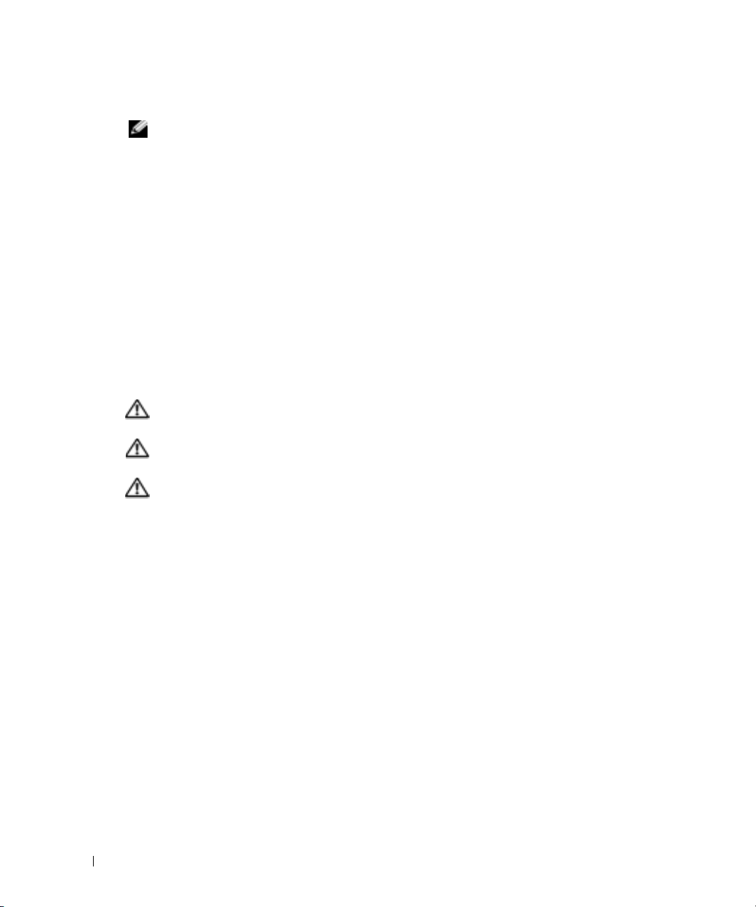
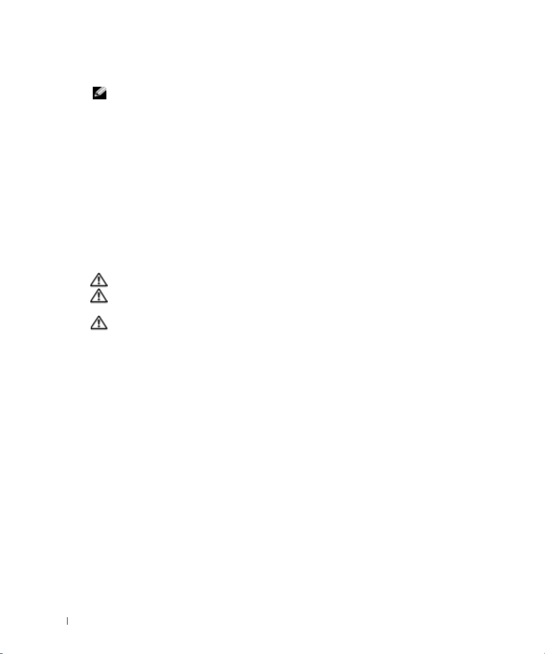
1
Place the supplied rack-mounting bracket on one side of the device, ensuring that the
mounting holes on the device line up to the mounting holes on the rack-mounting bracket.
Figure 1-1 illustrates where to mount the brackets.
Figure 1-1. Attaching the Brackets
2
Insert the supplied bolts into the rack-mounting holes and tighten with a screwdriver.
3
Repeat the process for the rack-mounting bracket on the other side of the device.
4
Insert the device into the 48.26 cm (19 inch) rack, ensuring that the rack-mounting holes on
the device line up to the mounting holes on the rack.
5
Secure the device to the rack with either the rack bolts or cage nuts and cage nut bolts with
washers (depending on the kind of rack you have). Fasten the bolts on bottom before
fastening the bolts on top. Ensure that the ventilation holes are not obstructed.
CAUTION: Ensure that the supplied rack bolts fit the pre-threaded holes on the rack.
Installing on a Flat Surface (Free-standing Device)
NOTE: We highly recommend that the device be mounted.
Install the device on a flat surface if you are not installing it on a rack. The surface must be able to
support the weight of the device and the device cables. The device is supplied with four
self-adhesive rubber pads.
1
Attach the self-adhesive rubber pads on each location marked on the bottom of the chassis.
2
Set the device on a flat surface, leaving 5.08 cm (2 inches) on each side and 12.7 cm
(5 inches) at the back.
3
Ensure that the device has proper ventilation.
Getting Started Guide 5
Page 8
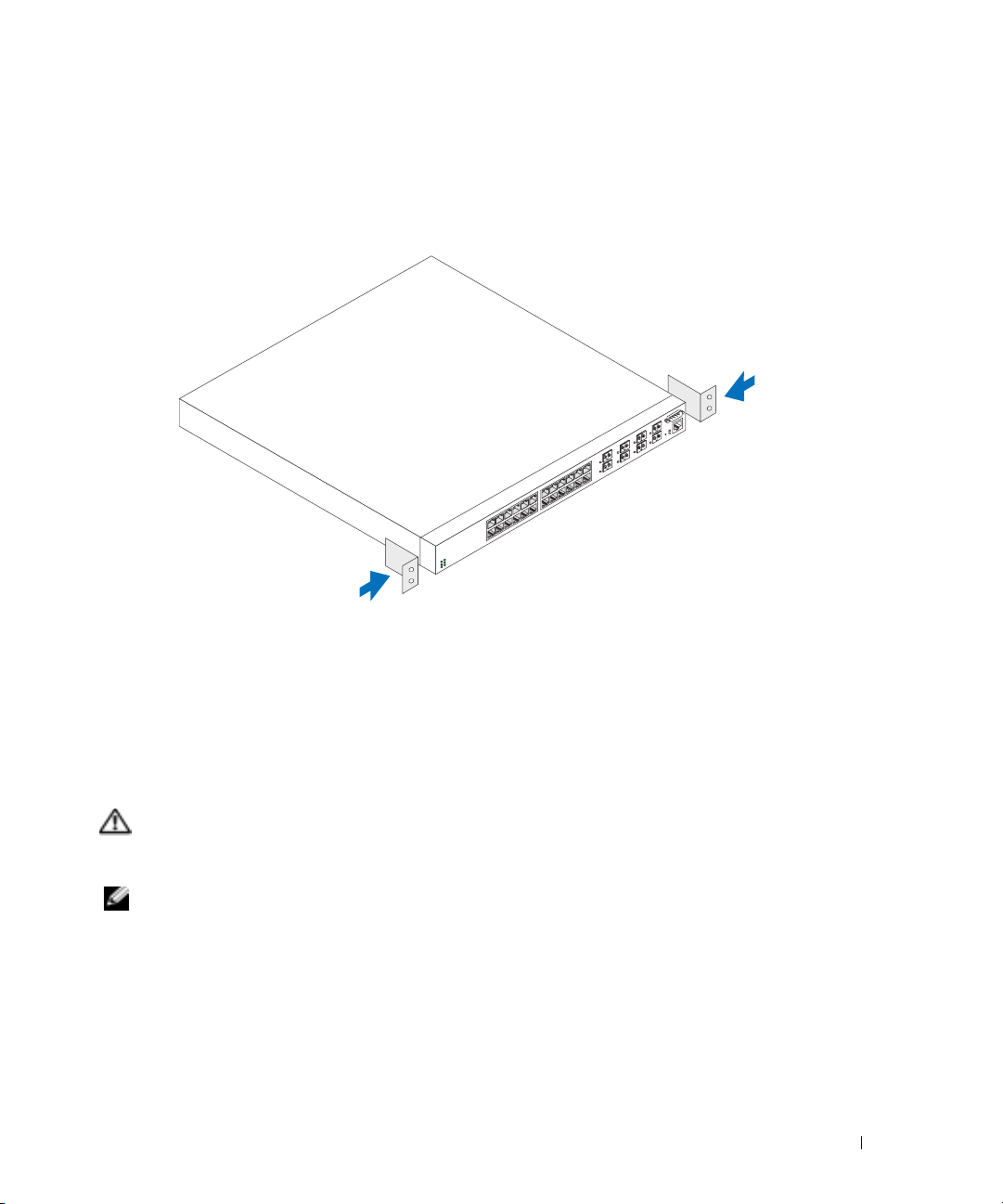
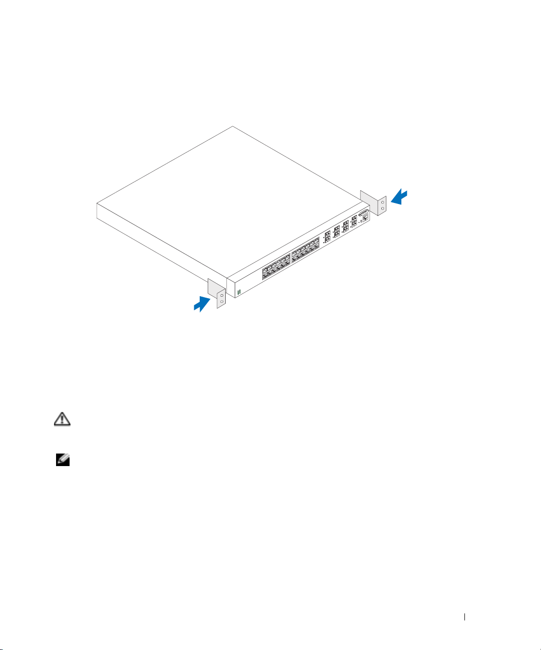
Connecting a Device to a Power Supply
Connect the supplied AC power cable to the AC power connector located on the back panel.
NOTE: Do not connect the power cable to a grounded AC outlet at this time. Connect the device to a
power source as described in the step detailed in “Starting and Configuring the Device."
NOTE: Read the safety information in the Product information Guide as well as the safety information for
other devices that connect to or support the switch.
Figure 1-2. Connecting Power Cable
www.dell.com | support.dell.com
6 Getting Started Guide
Page 9

Starting and Configuring the Device
After completing all external connections, connect a terminal to the device to configure the device.
Additional advanced functions are described in the
User Documentation
NOTE: Read the release notes for this product before proceeding. You can download the release notes
from the Dell Support website at support.dell.com.
NOTE: We recommend that you obtain the most recent version of the user documentation from the Dell
Support website at support.dell.com.
CD.
Connecting the Terminal to the Device
A console port on the device enables you to connect the device to a terminal desktop system
running terminal emulation software; for monitoring and configuring the device. The console port
connector is a male DB-9 connector, implemented as a data terminal equipment (DTE) connector.
To use the console port, the following is required:
• VT100-compatible terminal or a desktop or a portable system with a serial port, running
VT100 terminal emulation software.
• An RS-232 crossover cable with a female DB-9 connector for the console port and the
appropriate connector for the terminal.
Perform the following tasks to connect a terminal to the device console port:
1
Connect an RS-232 crossover cable to the terminal running VT100 terminal emulation software.
2
Configure the terminal emulation software as follows:
a
Select the appropriate serial port (serial port 1 or serial port 2) to connect to the console.
b
Set the data rate to 115200 baud.
c
Set the data format to 8 data bits, 1 stop bit, and no parity.
d
Set the flow control to none.
e
Select
VT100 for Emulation
f
Select Terminal keys for Function, Arrow, and Ctrl keys. Ensure that the setting is for
Terminal keys (not Microsoft
mode under
®
Windows® keys).
User's Guide
Properties
.
located on your
NOTICE: When using HyperTerminal with Microsoft Windows 2000, ensure that you have Windows 2000
Service Pack 2 or later installed. With Windows 2000 Service Pack 2, the arrow keys function properly in
HyperTerminal's VT100 emulation. Go to www.microsoft.com for more information on Windows 2000
service packs.
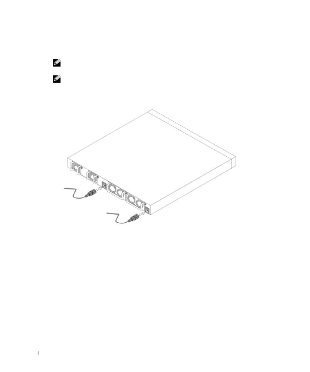
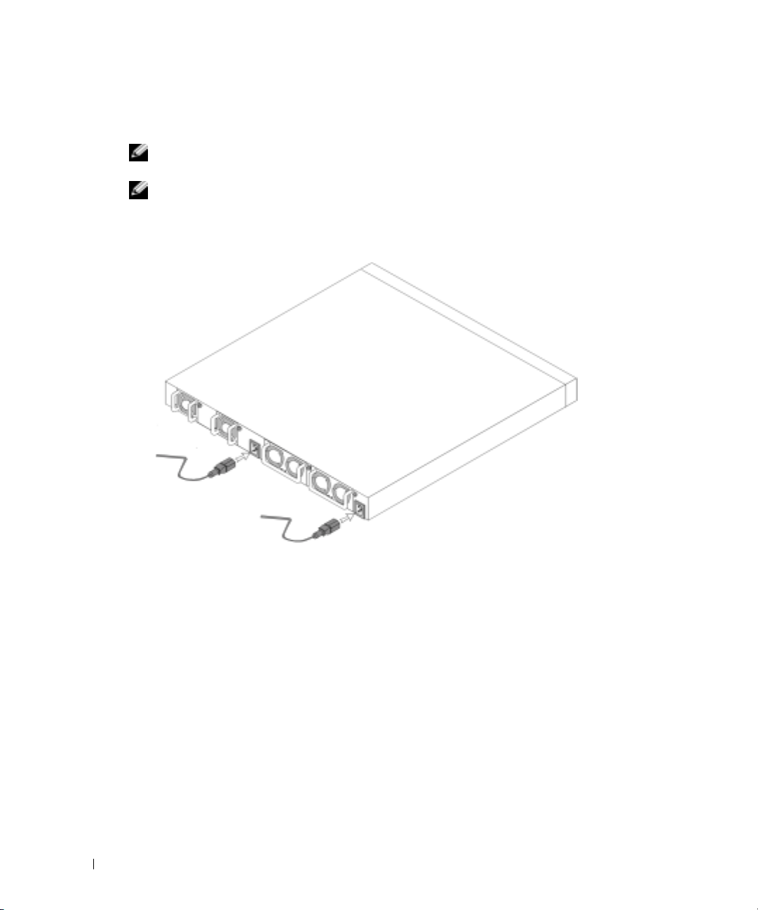
Connect the female connector of the RS-232 crossover cable directly to the device console
3
port, and tighten the captive retaining bolts. The PowerConnect 6024 and 6024F console
ports are located on the front panel as shown in Figure 1-3.
Getting Started Guide 7
Page 10
Figure 1-3. Connecting to the Console Port
to VT100 terminal device
www.dell.com | support.dell.com
Booting the Device
1
Ensure that the device console port is connected to a VT100 terminal device or VT100
terminal emulator via the RS-232 crossover cable.
2
Locate an AC power receptacle.
3
Deactivate the AC power receptacle.
4
Connect the device to the AC receptacle.
5
Activate the AC power receptacle.
When the power is turned on with the local terminal already connected, the device goes through a
power-on self-test (POST). POST runs every time the device is initialized and checks hardware
components to determine if the device is fully operational before completely booting. If POST
detects a critical problem , the program flow stops. If POST passes successfully, a valid executable
image is loaded into RAM. POST messages are displayed on the terminal and indicate test success
or failure. The boot process runs for approximately 30 seconds.
Initial Configuration
NOTE: The initial simple configuration procedure is based on the following assumptions:
• The PowerConnect device was never configured before and is in the same state as when you
received it.
• The PowerConnect device booted successfully.
• The console connection was established and the console prompt appears on the screen of a
VT100 terminal device.
to console port
8 Getting Started Guide
Page 11

The initial device configuration is performed through the console port. After the initial
configuration, you can manage the device either from the already-connected console port or
remotely through an interface defined during the initial configuration.
NOTE: The device is not configured with a default user name and password.
NOTE: All of the above settings are necessary to allow the remote management of the device through
Telnet (Telnet client) or HTTP (Web browser).
Before setting up the initial configuration of the device, obtain the following information from
your network administrator:
• The IP address to be assigned to the Out-of-Band Ethernet Management Port through which
the device is managed.
• The IP subnet mask for the network
• The IP address of the Out-of-Band Ethernet Management Port default gateway for
configuring the default route.
NOTE: For additional information about the Out-of-Band Ethernet Management Port see the User’s Guide.
Initial Configuration Procedure
You can perform the initial configuration using the Dell PowerConnect Easy Setup Wizard, or by
using the Command Line Interface (CLI). The Setup Wizard automatically starts when the device
configuration file is empty. You can invoke CLI by entering [ctrl+z] anytime during the wizard.
For more information on CLI initial configuration see the
User Guide
. This guide shows how to use
the Setup Wizard for initial device configuration. The Setup Wizard configures the following fields.
• SNMP Community String and SNMP Management System IP address (optional)
• Username and Password
• Out-of-Band Ethernet Management Port IP Address
• Out-of-Band Ethernet Management Port default gateway address
After the device completes the POST and is booted, the following information appears:
Welcome to Dell Easy Setup Wizard
The Setup Wizard guides you through the initial switch
configuration, and gets you up and running easily and quickly.
You can also skip the setup wizard, and enter CLI mode to
manually configure the switch if you prefer.
You can exit the Setup Wizard at any time by entering [ctrl+Z].
The system will prompt you with a default answer; by pressing
enter, you accept the default.
After you configure basic settings using the Setup Wizard, you can
manage the device from the Out-of-band ethernet management port.
Would you like to enter the setup wizard? (Y/N)[Y]
Getting Started Guide 9
Page 12

1
If you enter [N], the Setup Wizard exits. If there is no response within 60 seconds, the
Setup Wizard automatically exits and the CLI console prompt appears. If you enter [Y], the Setup
Wizard provides interactive guidance throughout the initial device configuration.
NOTE: If there is no response within 60 seconds, and there is a BootP server on the network, an address
is retrieved from the BootP server.
NOTE: You can exit the Setup Wizard at any time by entering [ctrl+z].
Wizard Step 1
If you enter [Y] the following information appears:
The system is not setup for SNMP management by default. To
www.dell.com | support.dell.com
manage the switch using SNMP (required for Dell Network
Manager) you can:
•
Setup the initial SNMP version 2 account now.
•
Return later and setup the SNMP version 2 account. (For more
information on setting up a SNMP version 2 account, see the
user documentation).
Would you like to setup the SNMP management interface now?
(Y/N)[Y]
1
Enter [N] to skip to Step 2 or enter [Y] to continue the Setup Wizard. If you enter [Y] the
following information appears:
To setup the SNMP management account you must specify the
management system IP address and the “community string” or
password that the particular management system uses to access
the switch. The wizard automatically assigns the highest access
level [Privilege Level 15] to this account. You can use Dell
Network Manager or other management interfaces to change this
setting later, and to add additional management system later.
For more information on adding management systems, see the user
documentation.
To add a management station:
Please enter the SNMP community string to be
used:[Dell_NetWork_Manager]
2
Enter the following: User SNMP community string, for example "MYSETUPWIZARD".
3
Press
Enter
10 Getting Started Guide
.
Page 13

Wizard Step 2
Please enter the IP address of the Management System (A.B.C.D)
or wildcard (0.0.0.0) to manage from any Management
Station:[0.0.0.0]
1
Enter
– Management System IP address for example “0.0.0.0”, or wildcard mask.
2
Press
Enter
.
Wizard Step 3
The following information appears:
Now we need to setup your initial privilege (Level 15) user
account. This account is used to login to the CLI and Web
interface. You may setup other accounts and change privilege
levels later. For more information on setting up user accounts
and changing privilege levels, see the user documentation.
To setup a user account:
Please enter the user name:
Please enter the user password:
Please reenter the user password:
1
Enter:
– User name, for example “admin”
– Password and password confirmation.
NOTE: If the first and second password entries are not identical, the wizard prompts you to enter
identical passwords.
Press
Enter
Enter
.
.
Getting Started Guide 11
2
3
Enter the password, for example "secret".
4
Press enter.
5
Confirm the password, by entering the identical string, for example, "secret".
6
Press
Page 14

Wizard Step 4
The following information appears:
Next, an IP address is setup. The IP address is defined on the
OOB port. This is the IP address you use to access the CLI, Web
interface, or SNMP interface for the switch.
To setup an IP address:
Please enter the IP address of the device (A.B.C.D):
Please enter the IP subnet mask (A.B.C.D or /nn):
1
Enter the IP address, for example 192.168.1.100.
2
Press
www.dell.com | support.dell.com
3
4
Wizard Step 5
Enter
Enter the IP subnet mask, for example 255.255.255.0
Press
Enter
The following information appears:
Finally, setup the default gateway. Please enter the IP address
of the gateway from which this network is reachable
(for example 192.168.1.1):
1
Enter the default gateway, for example, 192.168.1.1.
2
Press
Enter
The following information appears (as per the example parameters described):
.
.
.
This is the configuration information that has been collected:
SNMP Interface = MYSETUPWIZARD@0.0.0.0
User Account setup = admin
Password = **********
Management IP address = 192.168.1.100 255.255.255.0
Default Gateway = 192.168.1.1
12 Getting Started Guide
Page 15

Wizard Step 6
The following information appears:
If the information is correct, please select (Y) to save the
configuration, and copy to the start-up configuration file.
If the information is incorrect, select (N) to discard
configuration and restart the wizard: [Y/N]
1
Enter [Y] to complete the Setup Wizard or enter [N] to skip to restart the wizard. If you enter [Y]
the following information appears:
Configuring SNMP management interface.
Configuring user account.......
Configuring IP and subnet......
...............................
Thank you for using Dell Easy Setup Wizard. You will now enter
CLI mode.
Wizard Step 7
The CLI prompt appears.
You can now manage the device from the already connected Console port or remotely through
the Out-of-Band Ethernet Management Port interface defined during the initial configuration.
Getting Started Guide 13
Page 16

www.dell.com | support.dell.com
14 Getting Started Guide
Page 17

Dell™ PowerConnect™
6024/6024F 系统
使用入门指南
www.dell.com | support.dell.com
Page 18

注、注意和警告
注 : 注表示可以帮助您更好地使用计算机的重要信息。
注意 : 注意表示硬件的潜在损坏或数据丢失,并且告诉您如何避免此类问题。
警告 : 警告表示潜在的财产损坏、人身伤害或死亡。
____________________
本说明文件中的信息如有更改,恕不另行通知。
© 2004-2005 Dell Inc. 保留所有权利。
未经 Dell Inc. 书面许可,严禁以任何方式进行复制。
本文件中使用的商标 : Dell、 DELL 徽标和 PowerConnect 是 Dell Inc. 的商标; Microsoft 和 Windows 是 Microsoft Corporation 的注
册商标。
本说明文件中述及的其它商标和商品名称是指拥有相应标记和名称的公司或其制造的产品。 Dell Inc. 对不属于自己的商标和商品
名称不拥有任何专有权益。
型号 6024 和 6024F
2005 年 1 月 P/N N5382 修订版 A01
Page 19

安装
概览
本说明文件提供了安装、配置和操作 Dell™ PowerConnect™ 6024 和 6024F 系统的基本信
息。有关详情,请参阅用户说明文件 光盘中的 《用户指南》,或访问 Dell 支持 Web 站点
support.dell.com 以获取说明文件和软件的最新更新。
场所准备
PowerConnect 60xx 设备可以安装在标准的 48.26 厘米 (19 英寸)机架中或独自站立 (置
于桌面上)。 在安装该设备之前,请确保所选的安装位置满足以下场所要求:
•
电源
—
设备安装在容易接近的
•
常规
—
通过检查前面板上的
空隙
—
•
•
•
布线
明装置。
环境
95%
前方留有操作员进出的适当空隙。留有布线、电源连接和通风的空隙。
—
布线路径应避免电子噪声源,如无线电发射器、广播放大器、电源线路和荧光照
—
设备操作环境温度范围是
,非冷凝。
拆包
封装目录
拆封设备时,确保其中包括以下项目:
•
一个
PowerConnect
•
两根交流电源电缆
•
一根
RS-232
•
一个用于机架安装的机架固定套件 (两个固定支架、螺栓和锁紧螺帽)
•
一组用于独立式设备的自粘胶垫 (共包括四个)
•
用户说明文件 光盘
•
《使用入门指南》
•
安全和管制信息 说明文件
交叉电缆
设备
100-250
LED
伏交流电压、
指示灯是否点亮来确保电源已正确安装。
0 到 55
摄氏度 (
50-60
32 到 131
赫兹电源插座附近。
华氏度),相对湿度最高
使用入门指南 17
Page 20
拆封设备
注 : 在拆封设备前,请检查包装箱,如果有任何损坏迹象,请立即报告。
将包装箱放置在干净平坦的表面上,割断所有紧固包装箱的带子。
1
2
打开包装箱或移除包装箱顶盖。
3
小心地从包装箱中取出设备,并将其置于安全和干净的表面上。
4
除去所有包装材料。
5
检查产品和附件有无损坏。如有任何损坏,请立即报告。
安装设备
www.dell.com | support.dell.com
以下说明适用于 PowerConnect 60xx 系列设备。PowerConnect 6024 和 6024F 的前面板上均具有
控制台端口。
电源连接器位于设备的背面板上。我们建议同时连接两个热交换电源。
在机架中安装
警告 : 请勿使用机架安装套件悬挂工作台或办公桌下面的设备,也请勿将其连接到墙上。
警告 : 在继续操作之前,请断开所有电缆与设备的连接。如果设备底部附着有自粘垫,请将它
们全部移除。
警告 : 将多个设备安装到机架中时,请自下而上安装设备。
18 使用入门指南
Page 21
1
将所提供的机架固定支架置于设备的一侧,确保设备上的固定孔与机架固定支架上的固
定孔对齐。图
图 1-1. 连接支架
2
将提供的螺栓插入机架固定孔中并用螺丝刀拧紧。
3
对设备另一侧的机架固定支架重复该步骤。
4
将设备插入
1-1
图示说明了固定支架的位置。
48.26
厘米 (
19
英寸)机架中,确保设备上的机架固定孔与机架上的固定孔
对齐。
5
根据您所用机架的类型,使用机架螺栓或锁紧螺帽以及带有垫圈的锁紧螺帽螺栓将设备
固定到机架上。在拧紧顶部的螺栓前,先拧紧底部的螺栓。
警告 : 确保提供的机架螺栓与机架上的预制螺纹孔适配。
确保未阻塞通风孔。
安装到平面上 (独立式设备)
注 : 我们强烈建议将设备固定好。
如果不将设备安装到机架上,则请将其安装到平坦表面上。该表面必须能够支持设备和设
备电缆的重量。 设备附带四个自粘胶垫。
1
将自粘胶垫粘到机箱底部每个标记的位置。
2
将设备置于平面上,每侧留出
3
确保设备通风良好。
5.08
厘米
(2
英寸),后面留出
12.7
厘米
(5
英寸)。
使用入门指南 19
Page 22
连接设备至电源
将所提供的交流电源电缆连接到位于背面板上的交流电源连接器。
注 : 此时,请勿连接电源电缆至接地交流电源插座。 请按照 “启动和配置设备”中详述的步骤
将设备连接至电源。
注 : 请阅读 《产品信息指南》中的安全信息,以及连接至或支持该交换机的其它设备的安全信
息。
图 1-2. 连接电源电缆
www.dell.com | support.dell.com
20 使用入门指南
Page 23

启动和配置设备
完成所有外部连接后,将终端连接到设备以配置该设备。 其它高级功能在用户说明文件 光
盘上的 《用户指南》中说明。
注 : 在继续之前,请阅读本产品的发布注释。您可以从 Dell 支持 Web 站点 support.dell.com 下载
该发布注释。
注 : 我们建议您从 Dell 支持 Web 站点 support.dell.com 获取用户说明文件的最新修订版本。
连接终端至设备
设备上的控制台端口使您可以将设备连接至运行终端仿真软件的终端台式机系统,以监测
和配置设备。控制台端口连接器是一个作为数据终端设备 (DTE) 连接器实现的 DB-9 插头
连接器。
要使用控制台端口,必须具备以下条件:
• VT100
•
请执行以下任务,将终端连接到设备控制台端口:
1
2
注意 : 在 Microsoft Windows 2000 中使用 HyperTerminal 时,确保安装 Windows 2000 服务软件包 2
3
兼容终端或具有串行端口并运行
具有连接控制台端口的
DB-9
内孔连接器和适当的连接终端的连接器的
VT100
终端仿真软件的台式机或便携式系统。
RS-232
交叉电
缆。
将
RS-232
交叉电缆连接到运行
VT100
终端仿真软件的终端。
配置终端仿真软件设置如下:
a
选择适当的串行端口 (串行端口
b
设置数据速率为
c
设置数据格式为
d
设置流控制为
e
在 Properties
f
为功能、箭头和
Windows
或更高版本。 使用 Windows 2000 服务软件包 2,箭头键在 HyperTerminal 的 VT100 仿真中功能正
常。 Windows 2000 服务软件包的有关详情,请访问 www.microsoft.com。
将
RS-232
交叉电缆的内孔连接器直接连接到设备控制台端口,并拧紧系留固定螺栓。
PowerConnect 6024
115200
8
none
波特。
数据位、1 停止位,并且无奇偶校验。
(无)。
(属性)下,选择 VT100 for Emulation(VT100
Ctrl
®
键)。
键选择终端键。 确保设置用于终端键 (非
和
6024F
控制台端口均位于前面板上,如图
1
或串行端口 2)连接至控制台。
仿真)模式 。
Microsoft®
1-3
所示。
使用入门指南 21
Page 24
图 1-3. 连接至控制台端口
至 VT100 终端设备
www.dell.com | support.dell.com
引导设备
1
确保设备控制台端口通过
器。
2
找到交流电源插座。
3
去活交流电源插座。
4
将设备连接到交流电源插座。
5
激活交流电源插座。
当本地终端已连接并打开电源时,设备将进行开机自测 (POST)。 开机自测在设备每次初始
化时运行,并在完全引导之前检查硬件组件,以确定设备是否完全可操作。 如果开机自测
检测到严重问题,程序流将停止。如果成功通过开机自测,一个有效的可执行程序映像被
载入到随机存取存储器 (RAM) 中。 开机自测信息显示在终端上,并表明测试获得成功或发
生故障。 引导过程大约运行 30 秒钟。
初始配置
注 : 初始简单配置程序基于以下假定:
•
该
PowerConnect
• PowerConnect
•
控制台连接已建立,并且控制台提示符出现在
初始设备配置通过控制台端口进行。初始配置之后,您可以从已经连接的控制台端口管理
设备,或者通过初始配置期间定义的接口远程管理设备。
注 : 设备未配置默认用户名和密码。
至控制台端口
RS-232
交叉电缆连接到
VT100
终端设备或
VT100
设备以前从未配置过,并且设备的状态与您接收到时相同。
设备成功引导。
VT100
终端设备屏幕上。
终端仿真
22 使用入门指南
Page 25

注 : 要想通过远程登录 (远程登录客户机)或 HTTP (Web 浏览器)来远程管理设备,则所有
以上设置都是必需的。
在设置设备的初始配置之前,必须从网络管理员处获取以下信息:
•
将要分配给 “带外以太网管理端口”的
•
该网络的
•
“带外以太网管理端口”默认网关的
注 : 有关 “带外以太网管理端口”的其它信息,请参阅 《用户指南》。
初始配置程序
IP
子网掩码
IP
地址,通过该端口管理设备。
IP
地址,用来配置默认路由。
您可以使用 “Dell PowerConnect 简易安装向导”,或者使用 “命令行界面” (CLI),来执
行初始配置。当设备配置文件为空时,“安装向导”自动启动。在向导过程的任何时候,
您都可以通过输入 [ctrl+z] 调用 CLI。有关 CLI 初始配置的详情,请参阅 《用户指南》。
本指南显示了如何使用 “安装向导”进行初始设备配置。“安装向导”配置了以下字段。
•SNMP
•
•
•
团体字符串和
SNMP
管理系统
用户名和密码
带外以太网管理端口
IP
地址
带外以太网管理端口默认网关地址
IP
地址 (可选)
在设备完成开机自测并引导之后,以下信息出现:
Welcome to Dell Easy Setup Wizard
The Setup Wizard guides you through the initial switch
configuration, and gets you up and running easily and quickly.
You can also skip the setup wizard, and enter CLI mode to
manually configure the switch if you prefer.
You can exit the Setup Wizard at any time by entering [ctrl+Z].
The system will prompt you with a default answer; by pressing
enter, you accept the default.
After you configure basic settings using the Setup Wizard, you can
manage the device from the Out-of-band ethernet management
port.
Would you like to enter the setup wizard? (Y/N)[Y]
(欢迎使用 “Dell 简易安装向导”
“安装向导”将指导您进行初始交换机配置,帮助您简单快捷地进入工作状态。如果
您愿意,您也可以跳过安装向导,进入 CLI 模式以手动配置交换机。
您可以在任何时候通过输入 [ctrl+Z] 退出 “安装向导”。系统会用默认答案提示您;
按 Enter 键,您将接受默认值。
在您使用 “安装向导”配置完基本设置之后,您可以从带外以太网管理端口管理设备。
您要进入安装向导吗? (Y/N)[Y])
使用入门指南 23
Page 26

1
如果您输入
出,并且
过程中提供交互式的导航。
注 : 如果 60 秒之内无响应,并且网络中有 BootP 服务器,将从 BootP 服务器检索地址。
注 : 您可以在任何时候通过输入 [ctrl+Z] 来退出 “安装向导”。
向导步骤 1
如果您输入
The system is not setup for SNMP management by default. To
manage the switch using SNMP (required for Dell Network
Manager) you can:
www.dell.com | support.dell.com
•
Setup the initial SNMP version 2 account now.
•
Return later and setup the SNMP version 2 account. (For more
information on setting up a SNMP version 2 account, see the
user documentation).
Would you like to setup the SNMP management interface now?
(Y/N)[Y]
(系统默认不进行 SNMP 管理设置。若要使用 SNMP 管理交换机 (这是 “Dell 网络
管理器”要求的),您可以:
•
立即设置初始
•
稍后返回并且设置
户文档
[N]
,“安装向导”将退出。如果
CLI
控制台提示符出现。 如果您输入
[Y]
,以下信息出现:
)
。
SNMP
版本
2 帐号。
SNMP 版本 2
帐号。(有关设置
60
秒之内无响应,“安装向导”会自动退
[Y]
,“安装向导”将在整个初始设备配置
SNMP 版本 2
帐号的详情,请参阅用
您要立即设置 SNMP 管理接口吗? (Y/N)[Y])
1
输入
出现:
To setup the SNMP management account you must specify the
management system IP address and the “community string” or
password that the particular management system uses to access
the switch. The wizard automatically assigns the highest access
level [Privilege Level 15] to this account. You can use Dell
Network Manager or other management interfaces to change this
setting later, and to add additional management system later.
For more information on adding management systems, see the user
documentation.
24 使用入门指南
[N]
以跳至步骤 2,或者输入
[Y]
以继续 “安装向导”。如果您输入
[Y]
,以下信息
Page 27

To add a management station:
Please enter the SNMP community string to be
used:[Dell_NetWork_Manager]
(要设置 SNMP 管理帐号,您必须指定管理系统 IP 地址和 “团体字符串”或密码,
特定的管理系统可以用其来访问交换机。向导会自动分配最高访问级别 [ 优先权级别
15] 给此帐号。您随后可以使用 “Dell 网络管理器”或其它管理接口更改此设置,以
及添加附加的管理系统。有关添加管理系统的详情,请参阅用户文档。
要添加管理站:
请输入将要使用的 SNMP 团体字符串:[Dell_NetWork_Manager])
2
输入以下内容:用户
3
按 Enter 键。
向导步骤 2
SNMP
团体字符串,例如 “
MYSETUPWIZARD
”。
Please enter the IP address of the Management System (A.B.C.D)
or wildcard (0.0.0.0) to manage from any Management
Station:[0.0.0.0]
(请输入 “管理系统”的 IP 地址 (A.B.C.D),或者通配地址 (0.0.0.0) 以从任何 “管理
站”进行管理:[0.0.0.0])
1
输入
–
“管理系统”
2
按 Enter 键。
IP
地址,例如 “
0.0.0.0
”,或者通配掩码。
向导步骤 3
以下信息出现:
Now we need to setup your initial privilege (Level 15) user
account. This account is used to login to the CLI and Web
interface. You may setup other accounts and change privilege
levels later. For more information on setting up user accounts
and changing privilege levels, see the user documentation.
To setup a user account:
Please enter the user name:
Please enter the user password:
Please reenter the user password:
(现在我们需要设置您的初始优先权 [ 级别 15 ] 用户帐号。此帐号被用来登录到 CLI
和 Web 接口。您可以随后设置其它帐号并更改优先权级别。有关设置用户帐号和更改
优先权级别的详情,请参阅用户文档。
使用入门指南 25
Page 28

要设置用户帐号:
请输入用户名:
请输入用户密码:
请重新输入用户密码:)
1
输入:
–
用户名,例如 “
–
密码和密码确认。
注 : 如果第一次和第二次密码输入不一致,向导会提示您输入一致的密码。
按 Enter 键。
www.dell.com | support.dell.com
2
3
输入密码,例如 “
4
按
Enter
5
通过输入相同的字符串确认密码,例如,“
6
按 Enter 键。
向导步骤 4
以下信息出现:
Next, an IP address is setup. The IP address is defined on the
OOB port. This is the IP address you use to access the CLI, Web
interface, or SNMP interface for the switch.
键。
admin
”
secret
”。
secret
”。
To setup an IP address:
Please enter the IP address of the device (A.B.C.D):
Please enter the IP subnet mask (A.B.C.D or /nn):
下一步,设置
(
We b
要设置
请输入设备的
请输入
1
输入
2
按 Enter 键。
3
输入
4
按 Enter 键。
26 使用入门指南
IP
接口或
SNMP
IP
地址:
IP 地址 [A.B.C.D]
IP
子网掩码
IP
地址,例如
IP
子网掩码,例如
地址。
接口的
IP
地址定义在
IP
地址。
:
[A.B.C.D 或 /nn]
192.168.1.100
255.255.255.0
:)
OOB
端口上。这是您用来访问交换机的
CLI
、
Page 29

向导步骤 5
以下信息出现:
Finally, setup the default gateway. Please enter the IP address
of the gateway from which this network is reachable
(for example 192.168.1.1):
(
最后,设置默认网关。请输入使本网络可达的网关的
1
输入默认网关,例如,
2
按 Enter 键。
192.168.1.1
IP
地址[例如
192.168.1.1]:
以下信息出现 (按照所说明的实例参数):
This is the configuration information that has been collected:
SNMP Interface = MYSETUPWIZARD@0.0.0.0
User Account setup = admin
Password = **********
Management IP address = 192.168.1.100 255.255.255.0
Default Gateway = 192.168.1.1
这是收集到的配置信息:
(
SNMP 接口 = MYSETUPWIZARD@0.0.0.0
)
用户帐号设置
密码
管理
默认网关
向导步骤 6
= **********
IP
= admin
地址
= 192.168.1.100 255.255.255.0
= 192.168.1.1
)
以下信息出现:
If the information is correct, please select (Y) to save the
configuration, and copy to the start-up configuration file.
If the information is incorrect, select (N) to discard
configuration and restart the wizard:[Y/N]
(
如果信息是正确的,请选择
正确,选择
1
输入
[N]
以放弃配置,并且重新启动向导:
[Y]
以完成 “安装向导”,或者输入
[Y]
以保存配置,并将其复制到启动配置文件。如果信息不
[Y/N]
)
[N]
以跳至重新启动向导。如果您输入
下信息出现:
Configuring SNMP management interface.
[Y]
,以
使用入门指南 27
Page 30

Configuring user account.......
Configuring IP and subnet......
...............................
Thank you for using Dell Easy Setup Wizard. You will now enter
CLI mode.
正在配置
(
正在配置用户帐号
正在配置
www.dell.com | support.dell.com
...............................
感谢您使用 “
向导步骤 7
CLI
提示符出现。
您现在可以从已经连接的控制台端口管理设备,或者通过初始配置期间定义的 “带外以
太网管理端口”接口远程管理设备。
SNMP
IP
和子网
管理接口。
.......
......
Dell
简易安装向导”。您现在将进入
CLI
模式。
)
28 使用入门指南
Page 31

Systémy Dell™ PowerConnect™
6024/6024F
Začínáme
www.dell.com | support.dell.com
Page 32

Poznámky, upozornění a varování
POZNÁMKA:
UPOZORNĚNÍ:
POZNÁMKA označuje důležité informace, které pomáhají lepšímu využití počítače.
UPOZORNĚNÍ označuje nebezpečí poškození hardwaru nebo ztráty dat a popisuje, jak se lze problému vyhnout.
VAROVÁNÍ: VAROVÁNÍ upozorňuje na potenciální nebezpečí poškození majetku, úrazu nebo smrti.
____________________
Informace v tomto dokumentu se mohou bez předchozího upozornění změnit.
© 2004-2005 Dell Inc. Všechna práva vyhrazena.
Jakákoli reprodukce bez předchozího písemného povolení společnosti Dell Inc. je přísně zakázána.
Obchodní značky použité v tomto textu: Dell, logo DELL a PowerConnect jsou ochranné známky společnosti Dell Inc.; Microsoft a Windows
jsou registrované ochranné známky společnosti Microsoft Corporation.
Ostatní obchodní značky a názvy mohou být v tomto dokumentu použity bud’ v souvislosti s organizacemi, které si na tyto značky a názvy
činí nárok, nebo s jejich produkty. Vyjma vlastních si společnost Dell Inc. nečiní nárok na žádné jiné ochranné známky nebo obchodní názvy.
Modely 6024 a 6024F
Leden 2005 P/N N5382 Rev. A01
Page 33

Instalace
Přehled
Tento dokument obsahuje základní informace o instalaci, konfiguraci a provozu systémů Dell™
PowerConnect™ 6024 a 6024F. Další informace najdete v
disku CD s
odborné pomoci společnosti Dell
dokumentací
, nebo vyhledejte nejnovější aktualizace dokumentace a softwaru na webu
support.dell.com.
Příprava místa instalace
Zařízení PowerConnect 60xx lze instalovat do standardního regálu 48,26 cm (19 palců) nebo
umístit volně (na stole). Před instalací zařízení zkontrolujte, zda místo zvolené pro instalaci splňuje
následující požadavky:
•
Napájení – Zařízení se nachází v blízkosti snadno dostupné zásuvky 100 - 250 V ~, 50 - 60 Hz.
•
Obecné – Zkonntrolujte, zda indikátory na předním panelu svítí a zda je napájení zapojeno
správně.
•
Dostupnost – Uživatel má k jednotce zepředu volný přístup. Uvolněte přístup ke kabeláži,
napájecím kabelům a ventilaci.
•
Kabely – Kabeláž se nachází v bezpečné vzdálenosti od zdrojů elektrického šumu, např.
rádiových vysílačů, rozhlasových zesilovačů, silnoproudého vedení a zářivkového osvětlení.
•
Okolní teplota – rozsah okolní teploty v místě provozu zařízení je 0 až 55 C (32 až 131 F) při
relativní vlhkosti 95 procent bez kondenzace.
Příručka uživatele
, která je k dispozici na
Vybalení
Obsah balení
Při vybalování zkontrolujte, zda výrobek obsahuje následující položky:
•
1x zařízení PowerConnect
•
2x napájecí kabel
•
1x křížový kabel RS-232
•
1x sada pro instalaci do regálu (dvě montážní konzole, šrouby a pojistné matice)
•
1x sada samolepících gumových podložek pro volně stojící zařízení (včetně 4 podložek)
•
Disk CD
•
Příručka Začínáme
•
Dokument
s uživatelskou dokumentací
s právními a bezpečnostními informacemi
Začínáme
31
Page 34

Vybalení zařízení
POZNÁMKA:
nahlaste.
1
Umístěte krabici na čistou rovnou plochu a odstraňte z obalu všechny pásky.
2
Otevřete krabici nebo odstraňte její vrchní část.
3
Opatrně vyjměte zařízení z krabice a položte jej na bezpečné a čisté místo.
4
Odstraňte všechny obaly.
5
Zkontrolujte, zda výrobek nebo příslušenství nejsou poškozeny. Jakékoliv poškození okamžitě
oznamte dodavateli.
www.dell.com | support.dell.com
Montáž zařízení
Následující pokyny se týkají zařízení řady PowerConnect 60xx. Zařízení PowerConnect 6024 a 6024F jsou
vybavena konzolovým portem na předním panelu.
Konektory napájení se nacházejí na zadním panelu zařízení. Doporučujeme zapojit oba
synchronizované zdroje napájení.
Instalace do regálu
VAROVÁNÍ: Nepoužívejte konzole pro montáž zařízení pod stůl ani zařízení nepřipevňujte na stěnu.
VAROVÁNÍ: Než budete pokračovat, odpojte od zařízení všechny kabely. Odlepte všechny samolepící
gumové podložky ze spodní strany zařízení (jsou-li k zařízení připevněny).
VAROVÁNÍ: Pokud do regálu instalujete několik zařízení, postupujte vždy zdola nahoru.
Před vybalením zařízení zkontrolujte, zda není poškozen obal; případné poškození ihned
32
Začínáme
Page 35

1
Na jednu stranu zařízení umístěte dodávanou podpěru tak, aby otvory na zařízení odpovídaly
otvorům na podpěře. Na obrázku Obrázek 1-1 je uvedeno umístění montážních konzol.
Obrázek 1-1. Montáž konzol
2
Do otvorů pro montáž do regálu vložte šrouby a utáhněte šroubovákem.
3
Podobně nainstalujte podpěru na druhé straně zařízení.
4
Zasuňte zařízení do regálu o velikosti 48,26 cm (19 palců) a zkontrolujte, zda otvory pro
montáž na zařízení odpovídají otvorům v regálu.
5
Zajistěte zařízení k regálu regálovými šrouby nebo nebo pojistnými štouby a maticemi s
podložkami (v závislosti na typu regálu). Nejprve utáhněte dolní šrouby a potom horní šrouby.
Zkontrolujte, zda nejsou zakryty ventilační otvory.
VAROVÁNÍ: Zkontrolujte, zda dodané šroubky do regálu odpovídají otvorům se závity na regálu.
Instalace na rovnou plochu (volně stojící zařízení)
POZNÁMKA:
Důrazně doporučujeme zařízení ukotvit.
Pokud zařízení neinstalujete do regálu, umístěte jej na rovnou plochu. Povrch musí unést hmotnost
zařízení a kabeláže. Zařízení je dodáváno se čtyřmi lepícími gumovými podložkami.
1
Připevněte samolepící gumové podložky na označená místa na spodní části rámu.
2
Umístěte zařízení na rovný povrch a ponechte 5, 08 cm (2 palce) na každé straně a 12,7 cm
(5 palců) vzadu.
3
Zajistěte dostatečné větrání zařízení.
Začínáme
33
Page 36

Připojení zařízení ke zdroji napájení
Připojte dodaný napájecí kabel střídavého proudu ke konektoru napájení střídavým proudem na
zadním panelu.
POZNÁMKA:
ke zdroji napájení podle pokynů v části „Spuštění a konfigurace zařízení.“
POZNÁMKA:
informace pro jiná zařízení, která jsou připojena nebo zajišůují tento přepínač.
Obrázek 1-2. Připojení napájecího kabelu
www.dell.com | support.dell.com
V této chvíli ještě nepřipojujte napájecí kabel do uzemněné elektrické zásuvky. Připojte zařízení
Přečtěte si bezpečnostní informace v Informační příručka produktu a také bezpečnostní
34
Začínáme
Page 37

Spuštění a konfigurace zařízení
Po ukončení instalace všech externích připojení připojte zařízení k terminálu, aby se mohlo
nakonfigurovat. Další rozšířené funkce jsou popsány v
uživatelskou dokumentací
CD s
.
Příručka uživatele
, která se nachází na disku
POZNÁMKA:
dispozici ke stažení z webu odborné pomoci Dell Support
POZNÁMKA:
společnosti Dell
Než budete pokračovat, přečtěte si poznámky k verzi tohoto výrobku.Poznámky k verzi jsou k
support.dell.com.
Doporučujeme získat nejaktuálnější verzi uživatelské dokumentace z webu odborné pomoci
support.dell.com.
Připojení terminálu k zařízení
Konzolový port na zařízení umožňuje připojit jej ke stolnímu počítači, ve kterém je nainstalován
software pro terminálovou modulaci pro sledování a konfiguraci zařízení. Konektor konzolového
portu je zástrčkový konektor DB-9, implementovaný jako konektor datového vybavení terminálu
(DTE).
Pokud chcete používat konzolový port, je třeba následující vybavení:
•
Terminál, stolní nebo přenosný počítač kompatibilní s emulací VT100 se sériovým portem a s
nainstalovaným softwarem pro terminálovou modulaci VT100.
•
Křížový kabel RS-232 se zástrčkou DB-9 pro konzolový port a odpovídající konektor pro
terminál.
Podle následujících pokynů připojte terminál konzolového portu zařízení:
1
Připojte křížový kabel RS-232 k terminálu, ve které je spuštěn emulační software terminálu VT100.
2
Podle následujících pokynů nakonfigurujte software pro terminálovou modulaci:
a
Vyberte vhodný sériový port (sériový port 1 nebo sériový port 2), který se připojí ke
konzole.
b
Nastavte rychlost dat na 115200 baudů.
c
Nastavte datový formát na 8 datových bitů, 1 stop bit a žádnou paritu.
d
Nastavte regulaci toku na None (Žádná).
e
Ve
Vlastnostech
f
Pro klávesy Function (Funkce), Arrow (Šipka) a Ctrl zvolte možnost Terminal keys
(Klávesy terminálu). Zkontrolujte, zda je použito nastavení Terminal keys (Terminálové
klávesy) (nikoli klávesy Microsoft
vyberte jako Režim
®
emulace možnost VT100
Windows®).
.
UPOZORNĚNÍ:
zkontrolujte, zda je nainstalována aktualizace Windows 2000 Service Pack 2 nebo novější. V případě operačního
systému Windows 2000 s aktualizací Service Pack 2 fungují klávesy se šipkami v emulaci HyperTerminal VT100
správně. Další informace o aktualizacích Service Pack pro operační systém Windows 2000 najdete na webu
www.microsoft.com.
Používáte-li aplikaci HyperTerminal s operačním systémem Microsoft Windows 2000,
Začínáme
35
Page 38

3
Připojte zásuvkový konektor křížového kabelu RS-232 přímo ke konzolovému portu zařízení a
zajistěte šrouby. Konzolové porty PowerConnect 6024 a 6024F se nacházejí na předním
panelu viz Obrázek 1-3.
Obrázek 1-3. Připojení ke konzolovému portu
www.dell.com | support.dell.com
Zavedení zařízení
1
Zkontrolujte, zda je konzolový port zařízení připojen k zařízení terminálu VT100 nebo
terminalovému emulátoru VT100 pomocí křížového kabelu RS-232.
2
Vyhledejte zásuvku střídavého proudu.
3
Vypněte zásuvku střídavého proudu.
4
Připojte zařízení k elektrické zásuvce.
5
Zapněte zásuvku střídavého proudu.
Pokud je napájení zapnuté a místní terminál je již připojen, zařízení provede autotest při zapnutí
(POST). Test POST proběhne při každé inicializaci zařízení a zkontroluje hardwarové dokumenty,
aby ještě před úplným zavedením systému určil, zda je zařízení provozuschopné. Pokud během
automatického testu POST dojde k problému, program bude zastaven. Pokud test POST proběhne
úspěšně, do paměti RAM se načte platný spustitelný obraz (image). Hlášení testu POST se zobrazí
na terminálu a oznámí úspěšnost nebo neúspěšnost testu. Proces spouštění trvá přibližně 30
sekund.
K terminálovému zařízení VT100
Ke konzolovému portu
36
Začínáme
Page 39

Původní konfigurace
POZNÁMKA:
•
Zařízení PowerConnect ještě nikdy nebylo nakonfigurováno a nachází se v takovém stavu, v
Počáteční jednoduchá konfigurace vychází z následujících předpokladů:
jakém jste jej obdrželi.
•
Zařízení PowerConnect úspěšně zavedlo systém.
•
Připojení konzole bylo úspěšně navázáno a na obrazovce koncového zařízení VT100 se zobrazí
zpráva konzole.
Počáteční konfigurace zařízení se provádí prostřednictvím konzolového portu. Po počáteční
konfiguraci můžete spravovat zařízení z již nainstalovaného konzolového portu nebo vzdáleně
prostřednictvím rozhraní, které bylo definováno během počáteční konfigurace.
POZNÁMKA:
POZNÁMKA:
služby Telnet (klient služby Telnet) nebo HTTP (webový prohlížeč).
V zařízení není nakonfigurováno výchozí uživatelské jméno a heslo.
Veškerá výše uvedená nastavení jsou nezbytná pro vzdálenou správu zařízení prostřednictvím
Před provedením počáteční konfigurace zařízení vyžádejte od správce sítě následující informace:
•
Adresa IP, která má být přidělena portu pro správu Ethernetu mimo pásmo (Out-of-Band
Ethernet Management Port), prostřednictvím kterého je zařízení spravováno.
•
maska IP podsítě pro sí ,
•
Adresa IP výchozí brány portu pro správu Ethernetu mimo pásmo (Out-of-Band Ethernet
Management Port) pro konfiguraci výchozího směrování.
POZNÁMKA:
Port) najdete v
Další informace o portu pro správu Ethernetu mimo pásmo (Out-of-Band Ethernet Management
Příručka uživatele
.
Postup původní konfigurace
Počáteční konfiguraci můžete provést pomocí Průvodce snadným nastavením Dell PowerConnect
nebo pomocí rozhraní příkazového řádku (CLI). Když je soubor s konfigurací zařízení prázdný,
Průvodce nastavením se spustí automaticky. Rozhraní CLI můžete během Průvodce kdykoli vyvolat
stisknutím kláves [ctrl+z]. Další informace o počáteční konfiguraci CLI najdete v
uživatele
. V této příručce je pro počáteční konfiguraci zařízení uvedeno použití Průvodce
Příručka
nastavením. Průvodce nastavením konfiguruje následující pole.
•
Řetězec komunity SNMP a adresa IP systému správy SNMP (nepovinné)
•
Uživatelské jméno a Heslo
•
Adresa IP portu pro správu Ethernetu mimo pásmo (Out-of-Band Ethernet Management
Port)
•
Adresa výchozí brány portu pro správu Ethernetu mimo pásmo (Out-of-Band Ethernet
Management Port)
Začínáme
37
Page 40

Po dokončení automatického testu POST a spuštění zařízení se zobrazí následující informace:
Welcome to Dell Easy Setup Wizard
The Setup Wizard guides you through the initial switch
configuration, and gets you up and running easily and quickly.
You can also skip the setup wizard, and enter CLI mode to
manually configure the switch if you prefer.
You can exit the Setup Wizard at any time by entering [ctrl+Z].
The system will prompt you with a default answer; by pressing
enter, you accept the default.
After you configure basic settings using the Setup Wizard, you can
www.dell.com | support.dell.com
manage the device from the Out-of-band ethernet management port.
Would you like to enter the setup wizard? (Y/N)[Y]
(
Vítá vás Průvodce snadným nastavením Dell
ů
vodce nastavením vás provede počáteční konfigurací přepína
Pr
č
e tak, aby byl rychle a snadno k dispozici. Rovněž můžete Prův
odce nastavením p
ř
lze p
Pr
ů
vodce nastavením můžete kdykoli ukončit stisknutím kláves
[ctrl+Z].
Systém vám nabídne výchozí odpov
souhlasíte s výchozím nastavením.
Po nakonfigurování základních nastavení pomocí Pr
nastavením m
správu Ethernetu mimo pásmo (Out-of-Band Ethernet Management
Port).
Chcete zrušit Pr
1
Stisknutím klávesy [N] bude Průvodce nastavením ukončen. Pokud neodpovíte do 60 sekund,
Průvodce nastavením bude automaticky ukončen a zobrazí se příkazový řádek CLI. Stisknutím
klávesy [A] vás Průvodce nastavením interaktivně provede počáteční konfigurací zařízení.
ř
eskočit a přejít do režimu CLI, ve kterém
epínač nakonfigurovat ručně podle vlastních potřeb.
ě
d’; stisknutím klávesy Enter
ů
vodce
ů
žete spravovat zařízení prostřednictvím portu pro
ů
vodce instalací? (A/N)[A]
)
38
POZNÁMKA:
tohoto serveru.
POZNÁMKA:
Průvodce - krok 1
Po stisknutí klávesy [A] se zobrazí následující informace:
The system is not setup for SNMP management by default. To
manage the switch using SNMP (required for Dell Network
Manager) you can:
Začínáme
Pokud neodpovíte do 60 sekund a pokud se v síti nachází server BootP, bude adresa načtena z
Průvodce nastavením můžete kdykoli ukončit stisknutím kláves [ctrl+z].
Page 41

•
Setup the initial SNMP version 2 account now.
•
Return later and setup the SNMP version 2 account. (For more
information on setting up a SNMP version 2 account, see the
user documentation).
Would you like to setup the SNMP management interface now?
(Y/N)[Y]
(
Ve výchozí konfiguraci není systém nastaven pro správu SNMP.
Chcete-li spravovat p
Dell Network Manager), m
•
Nastavte počáteční účet SNMP verze 2.
•
Nastavte účet SNMP verze 2 později. (For more information on
ř
epínač pomocí SNMP (vyžadováno aplikací
ů
žete provést následující kroky:
setting up a SNMP version 2 account, see the user
documentation).
Chcete nastavit rozhraní pro správu SNMP? (AN)[A]
1
Stisknutím klávesy [N] přejdete na krok 2; stisknutím klávesy [A] budete pokračovat v
Průvodci nastavením. Po stisknutí klávesy [A] se zobrazí následující informace:
To setup the SNMP management account you must specify the
management system IP address and the “community string” or
password that the particular management system uses to access
the switch. The wizard automatically assigns the highest access
level [Privilege Level 15] to this account. You can use Dell
Network Manager or other management interfaces to change this
setting later, and to add additional management system later.
For more information on adding management systems, see the user
documentation.
)
To add a management station:
Please enter the SNMP community string to be
used:[Dell_NetWork_Manager]
(
Chcete-li nastavit účet pro správu SNMP, musíte určit adresu
IP systému pro správu a „
konkrétní systém pro správu používá pro p
Pr
ů
vodce automaticky přidělí tomuto účtu nejvyšší úroveň přís
ň
tupu [úrove
nastavení zm
oprávnění 15]. Budete-li chtít později tato
ě
nit nebo přidat další systémy pro správu, můžete
řetě
zec komunity“ nebo heslo, které
ř
ístup k přepínači.
použít aplikaci Dell Network Manager nebo jiná rozhraní pro spr
ř
ávu. Další informace o p
idávání systémů pro správu najdete v
uživatelské dokumentaci.
P
ř
idání správcovské stanice:
Začínáme
39
Page 42

Zadejte řetězec komunity SNMP, který má být
použit:[Dell_NetWork_Manager]
2
Zadejte následující informace: Řetězec komunity SNMP uživatele, například
„PRUVODCENASTAVENÍM“.
3
Stiskněte klávesu
Průvodce - krok 2
Please enter the IP address of the Management System (A.B.C.D)
or wildcard (0.0.0.0) to manage from any Management
Station:[0.0.0.0]
(
www.dell.com | support.dell.com
Zadejte adresu IP systému pro správu (A.B.C.D); chcete-li
provád
tupné znaky (0.0.0.0):[0.0.0.0]
1
Zadejte
–
adresu IP systému pro správu (například „0.0.0.0“), nebo masku zástupných znaků.
2
Stiskněte klávesu
Průvodce - krok 3
Zobrazí se následující informace:
Now we need to setup your initial privilege (Level 15) user
account. This account is used to login to the CLI and Web
interface. You may setup other accounts and change privilege
levels later. For more information on setting up user accounts
and changing privilege levels, see the user documentation.
)
ENTER
ě
t správu z libovolné správcovské stanice, zadejte zás
.
)
ENTER
.
40
Začínáme
To setup a user account:
Please enter the user name:
Please enter the user password:
Please reenter the user password:
(
Nyní je zapotřebí nastavit uživatelský účet s výchozím oprávn
ě
ním (úroveň 15). Tento účet se používá k přihlášení k rozhraní
CLI a k webovému rozhraní. Pozd
a m
ě
nit úrovně oprávnění. Další informace o nastavení
uživatelských ú
čtů
a o změnách úrovní oprávnění najdete v
ě
ji můžete nastavit další účty
uživatelské dokumentaci.
Natavení uživatelského ú
č
tu:
Zadejte uživatelské jméno:
Zadejte heslo uživatele:
Page 43

Znovu zadejte heslo uživatele:
1
Zadejte:
–
Uživatelské jméno, například „admin“
–
Heslo a znovu heslo pro potvrzení.
)
POZNÁMKA:
hesel.
2
Stiskněte klávesu
3
Zadejte heslo, například „secret“.
4
Stiskněte klávesu ENTER.
5
Zadáním totožného řetězce (například „secret“) potvrd’te heslo.
6
Stiskněte klávesu
Průvodce - krok 4
Pokud nejsou první a druhé zadání hesla totožné, budete vyzváni Průvodcem k zadání totožných
ENTER
ENTER
.
.
Zobrazí se následující informace:
Next, an IP address is setup. The IP address is defined on the
OOB port. This is the IP address you use to access the CLI, Web
interface, or SNMP interface for the switch.
To setup an IP address:
Please enter the IP address of the device (A.B.C.D):
Please enter the IP subnet mask (A.B.C.D or /nn):
Dále je nastavena adresa IP. Adresa IP je definována na portu
(
ř
OOB. Toto je adresa IP, kterou používáte pro p
č
i prostřednictvím rozhraní CLI, webového rozhraní nebo
ístup k přepína
rozhraní SNMP.
Nastavení adresy IP:
ř
Zadejte adresu IP za
Zadejte masku podsít
1
Zadejte adresu IP, například 192.168.1.100.
2
Stiskněte klávesu
3
Zadejte masku podsítě IP, například 255.255.255.0
4
Stiskněte klávesu
ENTER
ENTER
ízení (A.B.C.D):
ě
IP (A.B.C.D nebo /nn):
.
.
)
Začínáme
41
Page 44

Průvodce - krok 5
Zobrazí se následující informace:
Finally, setup the default gateway. Please enter the IP address
of the gateway from which this network is reachable
(for example 192.168.1.1):
(
Nakonec nastavte výchozí bránu. Zadejte adresu IP brány, ze
které je tato sí˙ dosažitelná (nap
1
Zadejte výchozí bránu, například 192.168.1.1.
2
Stiskněte klávesu
Zobrazí se následující informace (pro parametry uvedené v příkladu):
www.dell.com | support.dell.com
This is the configuration information that has been collected:
SNMP Interface = MYSETUPWIZARD@0.0.0.0
User Account setup = admin
Password = **********
Management IP address = 192.168.1.100 255.255.255.0
Default Gateway = 192.168.1.1
Toto jsou nashromážděné informace o konfiguraci:
(
Rozhraní SNMP = PRUVODCENASTAVENIM@0.0.0.0
Nastavení uživatelského ú
Heslo = **********
Adresa IP pro správu = 192.168.1.100 255.255.255.0
Výchozí brána = 192.168.1.1
ENTER
ř
íklad 192.168.1.1):
)
.
č
tu = admin
)
42
Začínáme
Page 45

Průvodce - krok 6
Zobrazí se následující informace:
If the information is correct, please select (Y) to save the
configuration, and copy to the start-up configuration file.
If the information is incorrect, select (N) to discard
configuration and restart the wizard: [Y/N]
(
Pokud jsou informace správné, stisknutím klávesy (A)
ě
konfiguraci uložte a zkopírujte spoušt
cí konfigurační soubor.
Pokud informace nejsou správné, stisknutím klávesy (N)
ů
konfiguraci zrušte a spus
1
Stisknutím klávesy [A] dokončíte Průvodce nastavením; stisknutím klávesy [N] spustíte Průvodce
znovu. Po stisknutí klávesy [A] se zobrazí následující informace:
Configuring SNMP management interface.
Configuring user account.......
Configuring IP and subnet......
...............................
Thank you for using Dell Easy Setup Wizard. You will now enter
CLI mode.
Konfigurování rozhraní SNMP pro správu.
(
Konfigurování uživatelského ú
Konfigurování IP a podsít
te Průvodce znovu: [A/N]
č
tu.......
ě
......
)
...............................
ě
kujeme vám za použití Průvodce snadným nastavením Dell. Nyní
D
ř
ejdete do režimu CLI.
p
)
Průvodce - krok 7
Zobrazí se zpráva rozhraní CLI.
Nyní můžete spravovat zařízení z již připojeného konzolového portu nebo vzdáleně
prostřednictvím portu pro správu Ethernetu mimo pásmo (Out-of-Band Ethernet
Management Port), který byl definován v počáteční konfiguraci.
Začínáme
43
Page 46

www.dell.com | support.dell.com
44
Začínáme
Page 47

Systèmes Dell™ PowerConnect™
6024/6024F
Guide de mise en route
www.dell.com | support.dell.com
Page 48

Remarques, avis et précautions
REMARQUE : Une REMARQUE indique des informations importantes qui peuvent vous aider à mieux utiliser votre
ordinateur.
AVIS : Un AVIS vous avertit d’un risque de dommage matériel ou de perte de données et vous indique comment éviter le
problème.
PRÉCAUTION : Une PRÉCAUTION indique un risque potentiel d'endommagement du matériel, de blessure corporelle
ou de mort.
____________________
Les informations contenues dans ce document sont sujettes à modification sans préavis.
© 2004-2005 Dell Inc. Tous droits réservés.
La reproduction de ce document, de quelque manière que ce soit, sans l'autorisation écrite de Dell Inc. est strictement interdite.
Marques utilisées dans ce document : Dell, le logo DELL et PowerConnect sont des marques de Dell Inc. ; Microsoft et Windows sont des
marques déposées de Microsoft Corporation.
D'autres marques et noms commerciaux peuvent être utilisés dans ce document pour faire référence aux entités se réclamant de ces marques
et de ces noms ou à leurs produits. Dell Inc. rejette tout intérêt propriétaire dans les marques et les noms commerciaux autres que les siens.
Modèles 6024 et 6024F
Janvier 2005 Réf. N5382 Rév. A01
Page 49

Installation
Présentation générale
Ce guide présente des informations de base concernant l'installation, la configuration et l'exécution
des systèmes Dell™ PowerConnect™ 6024 et 6024F. Pour en savoir plus, reportez-vous au
d'utilisation
support technique de Dell à l'adresse
documentation et des logiciels.
, qui se trouve sur votre CD
support.dell.com
Documentation utilisateur
pour obtenir les dernières mises à jour de la
ou consultez le site Web de
Préparation du site
Les appareils PowerConnect 60xx peuvent être montés dans un rack standard de 48,26 cm (19
pouces) ou tout simplement être autonomes (placés sur une table). Avant d'installer l'appareil,
assurez-vous que l'emplacement choisi pour l'installation satisfait aux exigences de site suivantes :
• Alimentation — L'appareil doit être installé près d'une prise électrique facile d'accès de 100 à
250 VCA, 50 à 60 Hz.
• Généralités — Assurez-vous que le bloc d'alimentation est bien installé en vérifiant que les
DEL qui se trouvent sur le panneau avant sont allumées.
• Dégagement — Il doit y avoir assez d'espace pour que l'opérateur puisse accéder à l'appareil.
Assurez-vous de laisser de l'espace pour le câblage, les branchements électriques et la ventilation.
• Câblage — Le câblage doit être acheminé afin d'éviter les sources d'interférence électrique
comme les transmetteurs radio, les amplificateurs de diffusion, les lignes d'énergie électrique
et les appareils d'éclairage à ampoule fluorescente.
• Environnement — La plage de température ambiante de fonctionnement de l'unité va de 0º à
55º C (32º à 131º F), à une humidité relative allant jusqu'à 95 pour cent, sans condensation.
Guide
Déballage
Contenu de l'emballage
Pendant le déballage de l'unité, assurez-vous que les articles suivants sont inclus :
• Un appareil PowerConnect
• Deux câbles d'alimentation en CA
• Un câble de jonction RS-232
• Un kit de montage pour une installation sur rack (deux languettes de montage, des boulons et
des écrous à cage)
• Un ensemble de tampons autocollants en caoutchouc destinés à l'appareil installé en
autonome (quatre tampons sont inclus)
•Le CD
Documentation utilisateur
Guide de mise en route 47
Page 50

• Guide de mise en route
• Le document d'
Déballage de l'appareil
REMARQUE : Avant de déballer l'appareil, inspectez l'emballage et signalez immédiatement tout signe de
dommage.
Placez le conteneur sur une surface plane et propre et coupez toutes les sangles qui le
1
maintiennent fermé.
2
Ouvrez le conteneur ou retirez la partie supérieure du conteneur.
3
Retirez soigneusement l'appareil du conteneur et placez-le sur une surface stable et propre.
www.dell.com | support.dell.com
4
Retirez tout le matériel d'emballage.
5
Vérifiez que le produit et ses accessoires ne sont pas endommagés. Signalez immédiatement
tout signe de dommage.
Montage du périphérique
Les instructions suivantes s'appliquent aux appareils PowerConnect de série 60xx. Les modèles
PowerConnect 6024 et 6024F sont dotés d'un port console sur le panneau avant.
Les connecteurs d'alimentation de l'appareil se trouvent sur le panneau arrière de celui-ci. Il est
recommandé de connecter les deux blocs d'alimentation remplaçables à chaud.
Installation dans un rack
Informations sur les réglementations et la sécurité
PRÉCAUTION : N'utilisez pas les kits de montage pour suspendre l'appareil sous une table ou un
bureau ou pour le fixer à un mur.
PRÉCAUTION : Déconnectez tous les câbles de l'appareil avant de continuer. Le cas échéant, retirez
tous les tampons autocollants du dessous de l'appareil.
PRÉCAUTION : Si vous montez plusieurs appareils dans un rack, faites-le en commençant par le bas.
48 Guide de mise en route
Page 51

1
Placez une des languettes métalliques de montage sur rack fournies sur un côté de l'appareil
en vous assurant que les trous de montage de celui-ci s'alignent sur les trous de montage de la
languette métallique de montage sur rack. La Figure 1-1 indique où monter les supports.
Figure 1-1. Fixation des supports
2
Insérez les vis fournies dans les trous de montage sur rack et serrez-les avec un tournevis.
3
Répétez ce processus pour la languette métallique de montage sur rack à installer sur l'autre
côté de l'appareil.
4
Insérez l'appareil dans le rack de 48,26 cm (19 pouces) en vous assurant que les trous de
montage sur rack situés sur l'appareil s'alignent sur les trous de montage du rack.
5
Fixez l'appareil au rack avec les boulons du rack ou des écrous à cage et des boulons d'écrou à
cage avec des rondelles (selon le type du rack dont vous disposez). Attachez les boulons du
bas avant ceux du haut. Assurez-vous que les trous de ventilation ne sont pas obstrués.
PRÉCAUTION : Assurez-vous que les boulons du rack fournis correspondent aux trous pré-percés
dans le rack.
Installation sur une surface plane (Appareil autonome)
REMARQUE : Il est vivement recommandé de monter l'appareil.
L'appareil doit être installé sur une surface plane s'il n'est pas installé dans un rack. La surface doit
pouvoir soutenir le poids du périphérique et de ses câbles. Quatre tampons autocollants en
caoutchouc sont fournis avec l'appareil.
1
Fixez les tampons autocollants en caoutchouc à chaque endroit marqué, sur la partie
inférieure du châssis.
Guide de mise en route 49
Page 52

2
Placez le périphérique sur une surface plane, tout en laissant 5,08 cm (2 pouces) de chaque
côté et 12,7 cm (5 pouces) à l'arrière.
3
Assurez-vous que l'appareil est bien aéré.
Connexion d'un périphérique sur un bloc d'alimentation
Raccordez le câble d'alimentation CA fourni au connecteur d'alimentation CA situé sur le panneau
arrière.
REMARQUE : Ne raccordez pas tout de suite le câble d'alimentation à une prise électrique CA mise à la
terre. Connectez l'appareil à une source d'alimentation électrique selon les étapes détaillées à la section
«Mise en route et configuration de l'appareil».
www.dell.com | support.dell.com
REMARQUE : Lisez les consignes de sécurité du Guide d'information sur le produit ainsi que celles des
périphériques qui se connectent au commutateur ou qui le prennent en charge.
Figure 1-2. Connexion du câble d'alimentation
50 Guide de mise en route
Page 53

Mise en route et configuration de l'appareil
Après avoir effectué toutes les connexions externes, raccordez un terminal à l'appareil afin de
configurer celui-ci. Vous trouverez la description des fonctions avancées supplémentaires dans le
Guide d'utilisation
REMARQUE : Avant de continuer, lisez les notes de mise à jour pertinentes à ce produit. Vous pouvez
télécharger les notes de mise à jour depuis le site Web de support technique de Dell à l'adresse
support.dell.com.
REMARQUE : Nous vous recommandons de vous procurer la révision la plus récente de la
documentation destinée à l'utilisateur depuis le site Web de support technique de Dell à l'adresse
support.dell.com.
Connexion du terminal à l'appareil
Le périphérique contient un port console qui permet une connexion à un terminal de bureau
exécutant un logiciel d'émulation de terminal destiné à la surveillance et à la configuration du
périphérique. Le connecteur de port console est en fait un connecteur DB-9 mâle, qui sert de
connecteur d'équipement de terminal de données (DTE).
Pour utiliser le port console, vous aurez besoin des éléments suivants :
• Un terminal ou un système de bureau ou portatif compatible VT100, doté d'un port série
fonctionnant sous un logiciel d'émulation de terminal VT100
• Un câble de jonction RS-232 doté d'un connecteur DB-9 femelle pour le port console et du
connecteur approprié pour le terminal
Pour connecter un terminal au port console de l'appareil :
1
Raccordez un câble de jonction RS-232 au terminal fonctionnant sous un logiciel d'émulation de
terminal VT100.
2
Configurez le logiciel d'émulation de terminal de la façon suivante :
a
Sélectionnez le port série approprié (port série 1 ou 2) à relier à la console.
b
Configurez le taux de transfert des données à 115200 bauds.
c
Configurez le format de données à 8 bits de données, 1 bit d'arrêt et aucune parité.
d
Configurez le contrôle du flux sur none (aucun).
e
Sous
f
Sélectionnez Touches du terminal pour les touches de fonction, de direction et Ctrl.
Assurez-vous que le paramètre est défini sur Touches du terminal (non pas Touches
Microsoft
qui se trouve sur le CD D
Propriétés
, sélectionnez le mode
®
Windows®).
ocumentation utilisateur.
VT100 pour émulation
.
Guide de mise en route 51
Page 54

AVIS : Si vous utilisez HyperTerminal avec Microsoft Windows 2000, assurez-vous que le Service Pack 2
de Windows 2000 ou version ultérieure est installé. Lorsque le Service Pack 2 de Windows 2000 est
installé, les touches de direction fonctionnent correctement avec l'émulation VT100 d'HyperTerminal.
Rendez-vous à l'adresse www.microsoft.com pour obtenir des informations sur les services packs de
Windows 2000.
Raccordez le connecteur femelle du câble de jonction RS-232 directement au port console de
3
l'appareil et serrez les boulons de fixation imperdables. Le port console PowerConnect 6024 et
6024F est situé sur le panneau avant, tel qu'illustré à la Figure 1-3.
Figure 1-3. Connexion au port console
www.dell.com | support.dell.com
Amorçage du périphérique
1
Assurez-vous que le port console de l'appareil est connecté à un dispositif terminal VT100 ou
un émulateur de terminal VT100 au moyen du câble de jonction RS-232.
2
Trouvez une prise secteur.
3
Désactivez la prise secteur.
4
Connectez l'appareil à la prise secteur.
5
Activez la prise secteur.
Lorsque l'alimentation fonctionne avec le terminal déjà connecté, le commutateur effectue un
auto-test de mise sous tension (POST). Le POST s'effectue chaque fois que le périphérique est
initialisé et vérifie les composants matériels afin de déterminer si le périphérique fonctionne
totalement avant de poursuivre l'amorçage. Si le POST détecte un problème critique, le flux du
programme s'arrête. Si le POST réussit, une image exécutable valide est chargée dans la mémoire
vive (RAM). Les messages de POST qui s'affichent sur le terminal indiquent la réussite ou l'échec
du test. Le processus d'amorçage dure environ 30 secondes.
vers le dispositif terminal VT100
vers le port console
52 Guide de mise en route
Page 55

Configuration initiale
REMARQUE : Les conditions suivantes doivent être remplies préalablement à la procédure de
configuration initiale :
• L'appareil PowerConnect n'a jamais été configuré auparavant et se trouve dans l'état où vous
l'avez reçu.
• L'initialisation de l'appareil PowerConnect a réussi.
• La connexion à la console est établie et l'invite de la console est affichée sur l'écran d'un
dispositif terminal VT100.
La configuration initiale de l'appareil se fait par l'intermédiaire du port console. Après la
configuration initiale, il est possible de gérer l'appareil depuis le port console déjà connecté ou à
distance au moyen d'une interface qui aura été définie au cours de la configuration initiale.
REMARQUE : L'appareil n'est pas configuré avec un nom d'utilisateur et un mot de passe par défaut.
REMARQUE : Tous les paramètres ci-dessus sont nécessaires pour la gestion à distance de l'appareil
par l'intermédiaire de Telnet (client Telnet) ou HTTP (navigateur Web).
Avant de procéder à la configuration initiale de l'appareil, procurez-vous les informations suivantes
auprès de l'administrateur de réseau :
• L'adresse IP à assigner au port de gestion Ethernet hors bande par lequel l'appareil est géré.
• Le masque de sous-réseau IP pour le réseau
• L'adresse IP de la passerelle par défaut du port de gestion Ethernet hors bande pour
configurer la gamme par défaut.
REMARQUE : Pour en savoir plus sur le port de gestion Ethernet hors bande, reportez-vous au Guide
d'utilisation.
Procédure de configuration initiale
Vous pouvez procéder à la configuration initiale à l'aide de l'Assistant Configuration aisée
PowerConnect de Dell ou de l'Interface de ligne de commande (CLI). l'Assistant Configuration
démarre automatiquement lorsque le fichier de configuration de l'appareil est vide. Vous pouvez
solliciter la CLI en tapant [ctrl+z] à tout moment lorsque l'Assistant est en fonctionnement. Pour
en savoir plus sur la configuration initiale de la CLI, reportez-vous au
Guide d'utilisation
. Ce guide
explique l'utilisation de l'Assistant Configuration pour la configuration initiale de l'appareil.
L'Assistant Configuration configure les champs suivants.
• Chaîne de communauté SNMP et adresse IP du système de gestion SNMP (facultatif)
• Nom d'utilisateur et mot de passe
• Adresse IP du port de gestion Ethernet hors bande
• Adresse de la passerelle par défaut du port de gestion Ethernet hors bande
Une fois que l'appareil a terminé le POST et est initialisé, les informations suivantes s'affichent :
Guide de mise en route 53
Page 56

Welcome to Dell Easy Setup Wizard
The Setup Wizard guides you through the initial switch
configuration, and gets you up and running easily and quickly.
You can also skip the setup wizard, and enter CLI mode to
manually configure the switch if you prefer.
You can exit the Setup Wizard at any time by entering [ctrl+Z].
The system will prompt you with a default answer; by pressing
enter, you accept the default.
After you configure basic settings using the Setup Wizard, you can
manage the device from the Out-of-band ethernet management port.
www.dell.com | support.dell.com
Would you like to enter the setup wizard? (Y/N)[Y]
(
Bienvenue sur l'Assistant Configuration aisée de Dell
L'Assistant Configuration vous guide tout au long de la
configuration initiale du commutateur, et vous permet d'être
rapidement et facilement opérationnel. Vous pouvez également
vous passer de l'Assistant Configuration et entrer en mode CLI
pour configurer le commutateur manuellement si vous le
souhaitez.
Vous pouvez quitter l'Assistant Configuration à tout moment en
tapant [ctrl+Z].
Le système vous propose une réponse par défaut ; vous pouvez
l'accepter en appuyant sur Entrée.
Après avoir configuré les paramètres de base à l'aide de
l'Assistant Configuration, vous pouvez gérer l'appareil à partir
du port de gestion ethernet hors bande.
Souhaitez-vous entrer dans l'Assistant Configuration ? (Y/N)[Y]
(O/N [O]
1
Si vous entrez [N], vous quittez l'Assistant Configuration. Si vous n'entrez pas une réponse
dans les 60 secondes, vous quittez automatiquement l'Assisant Configuration et l'invite de
console CLI s'affiche. Si vous entrez [Y], l'Assistant Configuration fournit des directives
interactives tout au long de la configuration initiale de l'appareil.
))
REMARQUE : Si vous n'entrez pas une réponse dans les 60 secondes, et que le réseau dispose d'un
serveur BootP, une adresse est extraite du serveur BootP.
REMARQUE : Vous pouvez quitter l'Assistant Configuration à tout moment en tapant [ctrl+Z].
54 Guide de mise en route
Page 57

Assistant Étape 1
Si vous entrez [Y], les informations suivantes s'affichent :
The system is not setup for SNMP management by default. To
manage the switch using SNMP (required for Dell Network
Manager) you can:
•
Setup the initial SNMP version 2 account now.
•
Return later and setup the SNMP version 2 account. (For more
information on setting up a SNMP version 2 account, see the
user documentation).
Would you like to setup the SNMP management interface now?
(Y/N)[Y]
(
Le système n'est pas configuré pour la gestion SNMP par
défaut. Pour gérer le commutateur à l'aide de SNMP (requis pour
le gestionnaire de réseau Dell), vous pouvez :
•
Configurer le compte SNMP initial version 2 maintenant.
•
Revenir plus tard pour configurer le compte SNMP version 2.
(Pour en savoir plus sur la configuration du compte SNMP
version 2, reportez-vous à la documentation de l'utilisateur).
Souhaitez-vous configurer l'interface de gestion SNMP
maintenant ? (Y/N)[Y] (O/N [O]
1
Entrez [N] pour sauter l'étape 2 ou entrez [Y] pour poursuivre avec l'Assistant Configuration.
Si vous entrez [Y], les informations suivantes s'affichent :
To setup the SNMP management account you must specify the
management system IP address and the “community string” or
password that the particular management system uses to access
the switch. The wizard automatically assigns the highest access
level [Privilege Level 15] to this account. You can use Dell
Network Manager or other management interfaces to change this
setting later, and to add additional management system later.
For more information on adding management systems, see the user
documentation.
))
To add a management station:
Please enter the SNMP community string to be
used:[Dell_NetWork_Manager]
(
Pour configurer le compte de gestion SNMP, vous devez spécifier
l'adresse IP du système de gestion et la «chaîne communautaire»
ou mot de passe utilisé par ce système de gestion particulier
pour accéder au commutateur. L'Assistant assigne automatiquement
Guide de mise en route 55
Page 58

le plus haut niveau d'accès [Niveau de privilège 15] à ce compte.
Vous pouvez utiliser le gestionnaire de réseau Dell ou une autre
interface de gestion pour modifier ce paramètre et ajouter un
autre système de gestion dans le futur. Pour en savoir plus sur
l'ajout de systèmes de gestion, reportez-vous à la documentation
de l'utilisateur.
Pour ajouter une Management station :
Veuillez saisir la chaîne de communauté SNMP à utiliser :
[Dell_NetWork_Manager] (Gestionnaire de réseau Dell
2
Tapez ce qui suit : Chaîne de communauté SNMP utilisateur, par exemple
«MYSETUPWIZARD».
www.dell.com | support.dell.com
3
Appuyez sur
Assistant Étape 2
Please enter the IP address of the Management System (A.B.C.D)
or wildcard (0.0.0.0) to manage from any Management
Station:[0.0.0.0]
(
Veuillez entrer l'adresse IP du système de gestion (A.B.C.D)
ou le caractère générique (0.0.0.0) à gérer à partir de
n'importe quelle Management Station :[0.0.0.0]
1
Enter (Entrée)
– Adresse IP du système de gestion, par exemple «0.0.0.0», ou masque de caractère
générique.
2
Appuyez sur
Entrée
Entrée
))
.
)
.
Assistant Étape 3
Les informations suivantes s'affichent :
Now we need to setup your initial privilege (Level 15) user
account. This account is used to login to the CLI and Web
interface. You may setup other accounts and change privilege
levels later. For more information on setting up user accounts
and changing privilege levels, see the user documentation.
To setup a user account:
Please enter the user name:
Please enter the user password:
Please reenter the user password:
56 Guide de mise en route
Page 59

(
Maintenant il faut configurer votre compte utilisateur
privilège initial (Niveau 15). On utilise ce compte pour se
connecter aux interfaces CLI et Web. Vous pouvez configurer
d'autres comptes et modifier les niveaux de privilège plus
tard. Pour en savoir plus sur la configuration des comptes
utilisateur et la modification des niveaux de privilège,
reportez-vous à la documentation de l'utilisateur.
Pour configurer un compte utilisateur :
Veuillez entrer le nom de l'utilisateur :
Veuillez entrer le mot de passe de l'utilisateur :
Veuillez entrer de nouveau le mot de passe de l'utilisateur
1
Saisissez :
– Nom d'utilisateur, par exemple «admin»
– Mot de passe et confirmation du mot de passe.
REMARQUE : Si le premier et le deuxième mot de passe ne sont pas saisis à l'identique, l'Assistant vous
invite à entrer des mots de passe identiques.
Appuyez sur
2
3
Saisissez le mot de passe, par exemple «secret».
4
Appuyez sur Entrée.
5
Confirmez le mot de passe en entrant une chaîne de caractères identique, par exemple
Entrée
.
«secret».
6
Appuyez sur
Entrée
.
:)
Assistant Étape 4
Les informations suivantes s'affichent :
Next, an IP address is setup. The IP address is defined on the
OOB port. This is the IP address you use to access the CLI, Web
interface, or SNMP interface for the switch.
To setup an IP address:
Please enter the IP address of the device (A.B.C.D):
Please enter the IP subnet mask (A.B.C.D or /nn):
Ensuite, une adresse IP est configurée. L'adresse IP est
(
définie sur le port OOB. Cette adresse IP est celle que vous
devez utiliser pour accéder à la CLI, à l'interface Web ou SNMP
du commutateur.
Pour configurer une adresse IP :
Veuillez entrer l'adresse IP de l'appareil (A.B.C.D) :
Veuillez entrer le masque de sous-réseau IP (A.B.C.D ou /nn
Guide de mise en route 57
) :)
Page 60

1
Entrez l'adresse IP, par exemple 192.168.1.100.
2
Appuyez sur
3
Entrez le masque de sous-réseau IP, par exemple 255.255.255.0
4
Appuyez sur
Assistant Étape 5
Les informations suivantes s'affichent :
Finally, setup the default gateway. Please enter the IP address
of the gateway from which this network is reachable
(for example 192.168.1.1):
(
www.dell.com | support.dell.com
Enfin, configurez la passerelle par défaut. Veuillez entrer
l'adresse IP de la passerelle qui permet l'accès à ce réseau
(par exemple 192.168.1.1
1
Entrez la passerelle par défaut, par exemple 192.168.1.1.
2
Appuyez sur
Les informations suivantes s'affichent (selon les paramètres utilisés comme exemple) :
This is the configuration information that has been collected:
SNMP Interface = MYSETUPWIZARD@0.0.0.0
User Account setup = admin
Password = **********
Entrée
Entrée
Entrée
.
.
) :)
.
Management IP address = 192.168.1.100 255.255.255.0
Default Gateway = 192.168.1.1
Voici les informations de configuration qui ont été réunies :
(
Interface SNMP = MYSETUPWIZARD@0.0.0.0
Configuration compte utilisateur = admin
Mot de passe = **********
Adresse IP de gestion = 192.168.1.100 255.255.255.0
Passerelle par défaut = 192.168.1.1
58 Guide de mise en route
)
Page 61

Assistant Étape 6
Les informations suivantes s'affichent :
If the information is correct, please select (Y) to save the
configuration, and copy to the start-up configuration file.
If the information is incorrect, select (N) to discard
configuration and restart the wizard: [Y/N]
(
Si les informations sont correctes, veuillez sélectionner (Y)
pour enregistrer la configuration et copier dans le fichier de
configuration de démarrage. Si les informations sont
incorrectes, sélectionnez (N) pour annuler la configuration et
redémarrer l'Assistant :[Y/N] (O/N
1
Entrez [Y] pour terminer la configuration avec l'Assistant Configuration ou [N] pour redémarrer
))
directement l'Assistant. Si vous entrez [Y], les informations suivantes s'affichent :
Configuring SNMP management interface.
Configuring user account.......
Configuring IP and subnet......
...............................
Thank you for using Dell Easy Setup Wizard. You will now enter
CLI mode.
Configuration interface de gestion SNMP.
(
Configuration compte utilisateur.......
Configuration IP et sous-réseau......
...............................
Merci d'avoir utilisé l'Assistant Configuration aisée de Dell.
Vous entrez maintenant en mode CLI
Assistant Étape 7
.)
L'invite CLI s'affiche.
Il est maintenant possible de gérer l'appareil depuis le port console déjà connecté ou à
distance au moyen de l'interface de port de gestion Ethernet hors bande définie au cours de la
configuration initiale.
Guide de mise en route 59
Page 62

www.dell.com | support.dell.com
60 Guide de mise en route
Page 63

Dell™ PowerConnect™
6024/6024F-Systeme
Handbuch zum Einstieg
www.dell.com | support.dell.com
Page 64

Anmerkungen, Hinweise und Vorsichtshinweise
ANMERKUNG: Eine ANMERKUNG macht auf wichtige Informationen aufmerksam, mit denen Sie den Computer besser
einsetzen können.
HINWEIS: Ein HINWEIS weist auf mögliche Schäden an der Hardware oder auf möglichen Datenverlust hin und be-
schreibt Ihnen, wie Sie dieses Problem vermeiden können.
VORSICHT: VORSICHT weist auf Gefahren hin, die zu Sachschäden, Personenschäden oder lebensgefährlichen Ver-
letzungen führen können.
____________________
Die in diesem Dokument enthaltenen Informationen können sich ohne vorherige Ankündigung ändern.
© 2004-2005 Dell Inc. Alle Rechte vorbehalten.
Nachdrucke jeglicher Art ohne die vorherige schriftliche Genehmigung von Dell Inc. sind strengstens untersagt.
Markenzeichen in diesem Text: Dell, das Logo von Dell und PowerConnect sind Marken von Dell Inc.; Microsoft und Windows sind eingetragene
Marken von Microsoft Corporation.
Andere in diesem Dokument möglicherweise verwendete Marken und Handelsbezeichnungen dienen ausschließlich der Identifikation der Firmen, denen diese Marken und Namen gehören, oder ihrer Produkte. Dell Inc. beansprucht kein Besitzrecht an Marken und Namen außer seinen
eigenen.
Modelle 6024 und 6024F
Januar 2005 Teilenr. N5382 Rev. A01
Page 65

Installation
Übersicht
Dieses Dokument stellt die grundlegenden Informationen zur Installation, Konfiguration und zum
Betrieb des Dell™ PowerConnect™ 6024 und 6024F Systems bereit. Weitere Informationen finden
Sie im
Benutzerhandbuch
chen Sie die Dell Support-Website über
Aktualisierungen für die Dokumentation und die Software zu erhalten.
Vorbereitung des Standorts
PowerConnect 60xx-Geräte können in einem 48,26 cm (19 Zoll) Standard-Rack installiert oder frei
-stehend auf einer Tischplatte betrieben werden. Stellen Sie bitte vor der Installation des Geräts
sicher, dass der gewählte Installationsort den folgenden Standortanforderungen entspricht:
• Strom – Die Einheit ist neben einer einfach zugänglichen 100–250 V Wechselstrom,
50–60 Hz-Steckdose installiert.
• Allgemein – Stellen Sie sicher, dass die Stromversorgung richtig hergestellt ist, indem Sie
überprüfen, dass die Leuchtdioden auf der Frontblende aufleuchten.
• Zwischenraum – Es muss ein angemessener Zwischenraum an der Vorderseite für den
Bediener vorhanden sein. Es muss ein angemessener Zwischenraum für die Verkabelung,
Stromversorgung und Entlüftung vorhanden sein.
• Verkabelung – Die Verkabelung wird so geleitet, dass Quellen elektrischer Störungen wie z. B.
Transmitter, Broadcastverstärker, Stromleitungen und Leuchtstoffröhren vermieden werden.
• Umgebungsbedingungen – Die Umgebungstemperatur für den Betrieb des Geräts beträgt 0
bis 55 °C bei einer relativen Luftfeuchtigkeit von bis zu 95 Prozent, nicht-kondensierend.
, das Ihnen auf der
support.dell.com
Dokumentations
, um Informationen über die neuesten
-CD zur Verfügung steht, oder besu-
Auspacken
Inhalt der Produktverpackung
Beim Auspacken des Geräts stellen Sie sicher, dass folgende Elemente vorhanden sind:
• Ein PowerConnect-Gerät
•Zwei Netzkabel
• Ein RS-232 gekreuztes Netzwerkkabel
• Ein Rackmontage-Kit zur Rackmontage (zwei Montagebleche, Schrauben und Gehäusemuttern)
• Ein Satz selbstklebende Gummiunterlagen für das frei stehende Gerät (vier Unterlagen
inbegriffen)
Benutzerdokumentation
•
CD
Handbuch zum Einstieg 63
Page 66

• Handbuch zum Einstieg
• Dokument mit
Auspacken des Geräts
ANMERKUNG: Vor dem Auspacken des Geräts überprüfen Sie bitte das Paket und melden Sie uns sofort
eventuelle Beschädigungen.
Setzen Sie den Container auf eine flache, saubere Oberfläche und entfernen Sie alle Riemen
1
am Container.
2
Öffnen Sie den Container oder entfernen Sie die Abdeckung des Containers.
3
Entnehmen Sie das Gerät vorsichtig aus dem Container und stellen Sie es auf eine sichere
www.dell.com | support.dell.com
und saubere Oberfläche.
4
Entfernen Sie das Verpackungsmaterial.
5
Überprüfen Sie das Gerät und die mitglieferten Zubehörteile auf Schäden. Melden Sie sofort
jegliche Schäden.
Einbau des Geräts
Die folgenden Anweisungen gelten für Geräte der PowerConnect 60xx Series. Die PowerConnect 6024
und 6024F haben die Konsolenschnittstelle an der Frontblende.
Der Netzanschluss des Geräts befindet sich auf der Rückseite. Es wird empfohlen, beide HotSwappable-Stromversorgungen anzuschließen.
Installieren in einem Rack
Zulassungs- und Sicherheitsinformationen
VORSICHT: Die Rackmontage-Kits sind nicht für die Aufhängung des Geräts unter einem Tisch oder
Schreibtisch oder zur Wandmontage bestimmt.
VORSICHT: Trennen Sie, bevor Sie fortfahren, alle Kabel vom Gerät ab. Entfernen Sie ggf. alle selbst-
klebenden Unterlagen von der Unterseite des Geräts.
VORSICHT: Wenn mehrere Komponenten in ein Rack eingebaut werden, bauen Sie die Komponenten
von unten nach oben ein.
64 Handbuch zum Einstieg
Page 67

1
Bringen Sie das Rackmontage-Abdeckblech an einer Seite des Geräts an und stellen Sie
sicher, dass die Montagelöcher in einer Linie mit den Montagelöchern des RackmontageAbdeckblechs stehen. Abbildung 1-1 zeigt, wo die Abdeckbleche zu befestigen sind.
Abbildung 1-1. Befestigung der Halterungen
2
Fügen Sie die mitgelieferten Schrauben in die Löcher der Rackmontage ein und ziehen Sie
sie mit einem Schraubendreher fest.
3
Wiederholen Sie dies beim Rackmontage-Abdeckblech auf der anderen Seite des Geräts.
4
Setzen Sie das 48,26 cm (19 Zoll)-Gerät in das Rack ein und stellen Sie sicher, dass die Rackmontagelöcher am Gerät in einer Linie mit den Einbaulöchern des Racks stehen.
5
Befestigen Sie das Gerät am Rack entweder mit den Rackschrauben oder den Gehäusemuttern und Gehäusemutterschrauben mit Unterlegscheiben (das hängt von Ihrem jeweiligen Rack ab). Ziehen Sie zuerst die unteren und dann die oberen Schrauben fest. Stellen Sie
sicher, dass die Lüftungslöcher nicht verstopft sind.
VORSICHT: Stellen Sie sicher, dass die mitgelieferten Rackschrauben in die Gewindelöcher am Rack
eingesteckt werden können.
Installation auf flacher Oberfläche (frei stehend)
ANMERKUNG: Es wird dringend empfohlen, das Gerät zu montieren.
Das Gerät muss auf einer flachen Oberfläche installiert werden, wenn es nicht auf einem Rack
installiert wird. Die Oberfläche muss in der Lage sein, das Gewicht des Geräts und der Gerätekabel
zu tragen. Dieses Geräte ist mit vier selbst-klebenden Gummiunterlagen ausgestattet.
1
Bringen Sie die selbstklebenden Gummiunterlagen an jeder markierten Stelle unten am Gehäuse an.
Handbuch zum Einstieg 65
Page 68

2
Stellen Sie das Gerät auf eine flache Oberfläche mit einem Abstand von 5,08 cm (2 Zoll) auf
jeder Seite und 12,7 cm (5 Zoll) auf der Rückseite.
3
Stellen Sie sicher, dass das Gerät ordnungsgemäß belüftet wird.
Anschließen eines Geräts an die Stromversorgung
Schließen Sie das Netzkabel an den Wechselstromanschluss auf der Rückseite an.
ANMERKUNG: Schließen Sie das Netzkabel jetzt nicht an eine geerdete Wechselstromsteckdose an.
Schließen Sie das Gerät an eine Stromquelle an, wie unter „Starten und Konfigurieren des Geräts” näher
beschrieben.
ANMERKUNG: Lesen Sie die Sicherheitshinweise im Produktinformationshandbuch sowie die Sicher-
www.dell.com | support.dell.com
heitshinweise für die Geräte, die mit dem Switch verbunden sind oder diesen unterstützen, aufmerksam
durch.
Abbildung 1-2. Anschließen des Netzkabels
66 Handbuch zum Einstieg
Page 69

Starten und Konfigurieren des Geräts
Nach der Vollendung aller externen Verbindungen schließen Sie ein Terminal an das Gerät an, um
das Gerät zu konfigurieren. Weitere zusätzliche Funktionen werden im
schrieben, dass sich auf Ihrer
ANMERKUNG: Bevor Sie fortfahren, lesen Sie bitte die Versionshinweise für dieses Produkt. Die
Versionshinweise können von der Dell Support-Website unter support.dell.com heruntergeladen
werden.
ANMERKUNG: Wir empfehlen Ihnen, die neueste Version der Benutzerdokumentation von der Dell
Support-Website unter support.dell.com herunterzuladen.
Benutzer- Dokumentations
-CD befindet.
Anschließen des Terminals an das Gerät
Das Gerät verfügt über eine Konsolenschnittstelle; diese ermöglicht den Anschluss an ein
Terminal-Desktopsystem, auf dem eine Terminal-Emulationssoftware zur Steuerung und Konfiguration des Geräts ausgeführt wird. Der Konsolen-Schnittstellenanschluss ist ein DB9-Anschluss,
der als Data Terminal Equipment (DTE) angeschlossen wurde.
Für die Verwendung der Konsolenschnittstelle ist Folgendes erforderlich:
• VT100-kompatibler Terminal, ein Desktop- oder ein Laptop-Computer mit einer seriellen
Schnittstelle und installierter VT100-Terminal-Emulation-Software.
• Ein RS-232 gekreuztes Netzwerkkabel mit einer DB9-Steckerbuchse für die Konsolenschnittstelle und dem entsprechenden Anschluss für das Terminal.
Führen Sie die folgenden Schritte aus, um ein Terminal mit der Konsolenschnittstelle des Geräts
zu verbinden:
1
Schließen Sie ein RS-232 gekreuztes Netzwerkkabel an das Terminal an, das unter einer VT100Terminal-Emulation-Software läuft.
2
Konfigurieren Sie die Terminal-Emulation-Software wie folgt:
a
Wählen Sie die entsprechende serielle Schnittstelle (serielle Schnittstelle 1 oder serielle
Schnittstelle 2) zum Anschluss an die Konsole.
b
Setzen Sie die Datenübertragungsrate auf 115200 Baud.
c
Setzen Sie das Datenformat auf 8 Datenbits, 1 Stoppbit und keine Parität.
d
Setzen Sie die Datenflusssteuerung auf „nicht”.
e
Wählen Sie unter
für Emulation) aus.
f
Wählen Sie Terminaltasten für Funktions-, Pfeil-, und Strg-Tasten. Stellen Sie sicher, dass
die Einstellung für Terminaltasten (nicht Microsoft
Properties
(Eigenschaften) den Modus
®
Windows®-Tasten) ist.
Benutzerhandbuch
VT100 for Emulation
be-
(VT100
Handbuch zum Einstieg 67
Page 70

HINWEIS: Wenn Sie HyperTerminal mit Microsoft® Windows® 2000 verwenden, stellen Sie sicher,
dass Sie das Windows 2000 Service-Pack 2 oder eine neuere Version installiert haben. Beim Windows
2000 Service-Pack 2 funktionieren die Pfeiltasten korrekt bei der VT100-Emulation von HyperTerminal.
Gehen Sie auf die Website www.microsoft.com, um weitere Informationen zu Windows 2000 Service
Packs zu erhalten.
Schließen Sie die Anschlussbuchse des RS-232 gekreuzten Netzwerkkabels direkt an der
3
Konsolenschnittstelle des Geräts an und ziehen Sie die Befestigungsschrauben fest. Die
Konsolenschnittstellen für PowerConnect 6024 und 6024F befinden sich auf der Frontblende, wie in Abbildung 1-3 gezeigt.
Abbildung 1-3. Anschließen an die Konsolenschnittstelle
www.dell.com | support.dell.com
zum VT100-Terminalgerät
zur Konsolenschnittstelle
Starten des Geräts
1
Stellen Sie sicher, dass die Konsolenschnittstelle des Geräts an ein VT100-Terminalgerät oder
einen VT100-Terminal-Emulator über das RS232 gekreuzte Netzwerkkabel angeschlossen ist.
2
Suchen Sie nach einer Netzanschlussbuchse.
3
Deaktivieren Sie die Netzanschlussbuchse.
4
Schließen Sie das Gerät an die Netzbuchse an.
5
Aktivieren Sie die Netzanschlussbuchse.
Wenn der Strom eingeschaltet wird und das lokale Terminal bereits angeschlossen ist, durchläuft
das Gerät einen Einschaltselbsttest (POST). POST wird jedes Mal ausgeführt, wenn das Gerät
initialisiert wird und überprüft die Hardware-Komponenten, um festzustellen, ob das Gerät vor
dem Booten vollständig betriebsbereit ist. Wenn beim Einschalt-Selbstest (POST) ein schwerwiegender Fehler auftritt, wird der Programmablauf unterbrochen. Wenn POST erfolgreich ausgeführt wurde, wird ein gültiges und ausführbares Bild in das RAM geladen. POST-Meldungen
werden auf dem Terminal angezeigt und zeigen einen Erfolg oder einen Fehlschlag des Tests. Der
Bootprozess dauert etwa 30 Sekunden.
68 Handbuch zum Einstieg
Page 71

Ursprüngliche Konfiguration
ANMERKUNG: Das Erstinstallationsverfahren beruht auf den folgenden Annahmen:
• Das PowerConnect-Gerät wurde niemals zuvor konfiguriert und ist in demselben Zustand, in
dem Sie es erhalten haben.
• Das PowerConnect-Gerät ist erfolgreich gestartet.
• Der Konsolenanschluss ist vorhanden und die Konsolen-Eingabeaufforderung wird auf dem
Bildschirm eines VT100-Terminalgeräts angezeigt.
Die Anfangsgerätekonfiguation wird über die Konsolenschnittstelle durchgeführt. Nach der Erstkonfiguration kann das Gerät über die bereits verbundene Konsolenschnittstelle gesteuert werden.
Alternativ ist auch eine Fernverwaltung über eine Schnittstelle möglich, die während der Erstkonfiguration definiert wurde.
ANMERKUNG: Das Gerät wird nicht mit einem Standard-Benutzernamen und einem Kennwort kon-
figuriert.
ANMERKUNG: Alle oben genannten Einstellungen sind notwendig, um die Fernverwaltung des Geräts
über Telnet (Telnet-Client) oder HTTP (Web-Browser) zu ermöglichen.
Bevor die Erstkonfiguration der Komponente erstellt wird, müssen die folgenden Informationen
vom Netzwerkadministrator eingeholt werden:
• Die IP-Adresse, die dem bandexternen Ethernet-Management-Port zugewiesen wird und über
den das Gerät gesteuert wird.
• Die IP-Teilnetzmaske für das Netzwerk.
• Die IP-Adresse des Standard-Gateways des bandexternen Ethernet-Management-Ports, das
verwendet wird, um den Standard-Route zu konfigurieren.
ANMERKUNG: Weiterführende Informationen über bandexterne Ethernet-Management-Ports finden
Sie im Benutzerhandbuch.
Verfahren für die Anfangskonfiguration
Sie können die Erstkonfiguration über den Dell PowerConnect-Easy Setup Wizard (benutzerdefinierter Installationsassistent) oder über die Befehlszeilenschnittstelle (CLI) durchführen. Der
Installationsassistent wird automatisch gestartet, wenn die Gerätekonfigurationsdatei leer ist. Sie
können die Befehlszeilenschnittstelle (CLI) über die Tastenkombination [Strg+Z] aufrufen, so
lange der Assistent aktiv ist. Weiterführende Informationen über die Erstkonfiguration mithilfe der
Befehlszeilenschnittstelle (CLI) finden Sie im
Benutzerhandbuch
. Dieses Handbuch enthält Informationen über die Erstkonfiguration des Geräts mithilfe des Installationsassistenten. Der Installationsassistent konfiguriert die folgenden Felder:
• IP-Adresse der SNMP-Communityzeichenfolge und des SNMP-Managementsystems
(optional)
• Benutzername und Kennwort
• IP-Adresse des bandexternen Ethernet-Management-Ports
Handbuch zum Einstieg 69
Page 72

• Adresse des Standard-Gateways des bandexternen Ethernet-Management-Ports
Nachdem das Gerät den Einschaltselbsttest (POST) und den Bootvorgang abgeschlossen hat,
werden die folgenden Informationen angezeigt:
Welcome to Dell Easy Setup Wizard
The Setup Wizard guides you through the initial switch
configuration, and gets you up and running easily and quickly.
You can also skip the setup wizard, and enter CLI mode to
manually configure the switch if you prefer.
You can exit the Setup Wizard at any time by entering [ctrl+Z].
The system will prompt you with a default answer; by pressing
www.dell.com | support.dell.com
enter, you accept the default.
After you configure basic settings using the Setup Wizard, you can
manage the device from the Out-of-band ethernet management port.
Would you like to enter the setup wizard? (Y/N)[Y]
(
Herzlich willkommen beim „Easy Setup Wizard” (benutzerdefi-
nierter Installationsassistent) von Dell!
Der Installationsassistent führt Sie durch die Erstkonfigura-
tion des Switches und hilft Ihnen dabei, das System schnell und
einfach in Betrieb zu nehmen. Sie können, falls Sie dies wünschen, den Installationsassistenten umgehen und stattdessen den
CLI-Modus aktivieren, um den Switch manuell zu konfigurieren.
Sie können den Installationsassistenten jederzeit über die
Tastenkombination [Strg+Z] beenden.
Das System zeigt Ihnen eine Standardantwort an. Wenn Sie die
Eingabetaste drücken, nehmen Sie die Standardeinstellungen an.
Nachdem Sie die Grundeinstellungen über den Installationsassistenten vorgenommen haben, können Sie das Gerät über den
bandexternen Ethernet-Management-Port steuern.
Möchten Sie den Installationsassistenten starten? (J/N)[J]
1
Wenn Sie [N] eingeben, wird der Installationsassistent geschlossen. Wenn das System innerhalb von 60 Sekunden keine Antwort erhält, wird der Installationsassistent automatisch geschlossen und die Befehlszeichenschnittstelle (CLI) wird angezeigt. Wenn Sie [J] eingeben, führt
Sie der Installationsassistent durch den gesamten Prozess der Erstkonfiguration des Geräts.
)
ANMERKUNG: Wenn das System innerhalb von 60 Sekunden keine Antwort erhält und im Netzwerk
kein BootP-Server installiert ist, wird eine Adresse vom BootP-Server abgerufen.
ANMERKUNG: Sie können den Installationsassistenten jederzeit über die Tastenkombination [Strg+Z]
beenden.
70 Handbuch zum Einstieg
Page 73

Schritt 1
Wenn Sie [J] eingeben, werden die folgenden Informationen angezeigt:
The system is not setup for SNMP management by default. To
manage the switch using SNMP (required for Dell Network
Manager) you can:
•
Setup the initial SNMP version 2 account now.
•
Return later and setup the SNMP version 2 account. (For more
information on setting up a SNMP version 2 account, see the
user documentation).
Would you like to setup the SNMP management interface now?
(Y/N)[Y]
(
Das System ist nicht standardmäßig für eine Steuerung über
SNMP konfiguriert. Führen Sie die folgenden Schritte aus, um
den Switch über SNMP zu steuern (erforderlich für den Dell
Netz-werk-Manager):
•
Eingangskonto für SNMP Version 2 jetzt einrichten.
•
SNMP-Konto Version 2 später einrichten. (Weitere Informationen
über die Einrichtung eines SNMP-Kontos der Version 2 finden
Sie in der Benutzerdokumentation).
Möchten Sie die SNMP-Managementschnittstelle jetzt installieren? (J/N)[J]
)
1
Geben Sie [N] ein, wenn Sie Schritt 2 auslassen möchten, oder geben Sie [J] ein, um den
Installationsassistenten fortzusetzen. Wenn Sie [J] eingeben, werden die folgenden Informationen angezeigt:
To setup the SNMP management account you must specify the
management system IP address and the “community string” or
password that the particular management system uses to access
the switch. The wizard automatically assigns the highest access
level [Privilege Level 15] to this account. You can use Dell
Network Manager or other management interfaces to change this
setting later, and to add additional management system later.
For more information on adding management systems, see the user
documentation.
To add a management station:
Please enter the SNMP community string to be
used:[Dell_NetWork_Manager]
Handbuch zum Einstieg 71
Page 74

(
Für das Einrichten eines SNMP-Steuerungskontos müssen Sie die
Adresse des Verwaltungssystems und die „Communityzeichenfolge”
oder das Kennwort festlegen, die das Verwaltungssystem verwendet, um auf den Switch zuzugreifen. Der Assistent vergibt
automatisch die höchste Zugriffsklasse [Zugriffsstufe 15] für
dieses Konto. Sie können den Netzwerk-Manager von Dell oder
andere Managementschnittstellen verwenden, um diese Einstellungen später zu ändern oder um ein zusätzliches Managementsystem zu installieren. Weitere Informationen zum Hinzufügen
von Managementsystemen finden Sie in Ihrer Benutzerdokumentation.
www.dell.com | support.dell.com
So fügen Sie eine Management Station hinzu:
Geben Sie die zu verwendende SNMP-Communityzeichenfolge ein:
[Dell_NetWork_Manager]
2
Geben Sie hier Folgendes ein: SNMP-Communityzeichenfolge des Benutzers, z. B.
„MYSETUPWIZARD”.
3
Drücken Sie erneut die
Schritt 2
Please enter the IP address of the Management System (A.B.C.D)
or wildcard (0.0.0.0) to manage from any Management
Station:[0.0.0.0]
(
Geben Sie die IP-Adresse des Managementsystems (A.B.C.D) oder
eine Wildcard (0.0.0.0) ein, um die Steuerung von jeder
Management Station aus zu ermöglichen:[0.0.0.0]
1
Enter
– IP-Adresse des Managementsystems, z. B. „0.0.0.0”, oder eine Wildcardmaske.
2
Erneut
Eingabe
Schritt 3
Es werden die folgenden Informationen angezeigt:
Now we need to setup your initial privilege (Level 15) user
account. This account is used to login to the CLI and Web
interface. You may setup other accounts and change privilege
levels later. For more information on setting up user accounts
and changing privilege levels, see the user documentation.
drücken.
)
Eingabetaste
.
)
To setup a user account:
Please enter the user name:
72 Handbuch zum Einstieg
Page 75

Please enter the user password:
Please reenter the user password:
Richten Sie nun Ihr anfängliches Zugangsbenutzerkonto
(
(Stufe 15) ein. Dieses Konto wird für die Anmeldung an der
Befehlszeilenschnittstelle (CLI) und am Internet verwendet. Sie
können später weitere Konten einrichten und Zugriffsstufen
ändern. Weitere Informationen zum Einrichten von Benutzerkonten
und zum Ändern von Zugriffsstufen finden Sie in der Benutzerdokumentation.
So richten Sie ein Benutzerkonto ein:
Geben Sie den Benutzernamen ein:
Geben Sie das Benutzerkennwort ein:
Geben Sie das Benutzerkennwort noch einmal ein:
1
Geben Sie hier Folgendes ein:
)
– Benutzername, z. B. „admin”
– Kennwort und Kennwortbestätigung.
ANMERKUNG: Wenn die Eingaben des ersten und des zweiten Kennworts nicht übereinstimmen,
fordert Sie der Assistent auf, noch einmal identische Kennwörter einzugeben.
Erneut
2
3
Geben Sie das Kennwort ein, z. B. „secret”.
4
Drücken Sie die Eingabetaste.
5
Bestätigen Sie das Kennwort, indem Sie noch einmal die identische Zeichenfolge eingeben,
Eingabe
drücken.
z. B. „geheim”.
6
Erneut
Schritt 4
Eingabe
drücken.
Es werden die folgenden Informationen angezeigt:
Next, an IP address is setup. The IP address is defined on the
OOB port. This is the IP address you use to access the CLI, Web
interface, or SNMP interface for the switch.
To setup an IP address:
Please enter the IP address of the device (A.B.C.D):
Please enter the IP subnet mask (A.B.C.D or /nn):
Handbuch zum Einstieg 73
Page 76

(
Als Nächstes wird eine IP-Adresse eingerichtet. Diese IPAdresse ist auf dem OOB-Port definiert. Es ist die IP-Adresse,
die Sie für den Zugang zur Befehlszeilenschnittstelle (CLI),
das Internet oder die SNMP-Schnittstelle für den Switch benötigen.
So richten Sie eine IP-Adresse ein:
Bitte geben Sie die IP-Adresse des Geräts ein (A.B.C.D):
Bitte geben Sie die IP-Teilnetzmaske (A.B.C.D oder /nn) ein:
1
Geben Sie nun die IP-Adresse ein, z. B. 192.168.1.100.
2
www.dell.com | support.dell.com
Drücken Sie die
3
Geben Sie die IP-Teilnetzmaske ein, beispielsweise 255.255.255.0
4
Eingabe
Schritt 5
Es werden die folgenden Informationen angezeigt:
Finally, setup the default gateway. Please enter the IP address
of the gateway from which this network is reachable
(for example 192.168.1.1):
(
Nun können Sie das Standard-Gateway einrichten. Bitte geben
Sie die IP-Adresse des Gateways ein, von dem aus dieses
Netzwerk erreicht werden kann (z. B. 192.168.1.1):
1
Geben Sie das Standard-Gateway ein, z. B. 192.168.1.1.
2
Erneut
Eingabe
Daraufhin werden die folgenden Informationen angezeigt (wie in den Beispielparametern
beschrieben):
This is the configuration information that has been collected:
SNMP Interface = MYSETUPWIZARD@0.0.0.0
drücken.
Eingabetaste
drücken.
)
.
)
User Account setup = admin
Password = **********
Management IP address = 192.168.1.100 255.255.255.0
Default Gateway = 192.168.1.1
Es wurden die folgenden Konfigurationsdaten ermittelt:
(
SNMP-Schnittstelle = MYSETUPWIZARD@0.0.0.0
Setup Benutzerkonto = admin
74 Handbuch zum Einstieg
Page 77

Kennwort = **********
Management-IP-Adresse = 192.168.1.100 255.255.255.0
Standard-Gateway = 192.168.1.1
Schritt 6
Es werden die folgenden Informationen angezeigt:
If the information is correct, please select (Y) to save the
configuration, and copy to the start-up configuration file.
If the information is incorrect, select (N) to discard
configuration and restart the wizard: [Y/N]
(
Wenn die Daten korrekt anzeigt werden, klicken Sie bitte auf
)
(J), um die Konfiguration zu speichern und die Startup-Konfigurationsdatei zu kopieren. Sollten die Daten nicht korrekt
sein, klicken Sie bitte auf (N), um die Konfiguration zu verwerfen und den Assistenten erneut aufzurufen: [J/N]
1
Geben Sie [J] ein, um den Installationsassistenten zu beenden oder [N] ein, um ein erneutes
Starten des Assistenten zu übergehen. Wenn Sie [J] eingeben, werden die folgenden Informationen angezeigt:
Configuring SNMP management interface.
Configuring user account.......
Configuring IP and subnet......
...............................
Thank you for using Dell Easy Setup Wizard. You will now enter
CLI mode.
)
Konfigurieren der SNMP-Managementschnittstelle.
(
Konfigurieren des Benutzerkontos.......
Konfigurieren von IP und Subnetz......
...............................
Vielen Dank, dass Sie den benutzerdefinierten Installationsassistenten von Dell verwendet haben. Sie gelangen jetzt in den
CLI-Modus.
)
Handbuch zum Einstieg 75
Page 78

Schritt 7
Die Befehlszeilenschnittstelle (CLI) wird angezeigt.
Sie können das Gerät nun über die bereits verbundene Konsolenschnittstelle steuern. Alternativ ist auch eine Fernverwaltung über die bandexterne Ethernet-Management-PortSchnittstelle möglich, die während der Erstkonfiguration definiert wurde.
www.dell.com | support.dell.com
76 Handbuch zum Einstieg
Page 79

Συστήµατα Dell™
PowerConnect™ 6024/6024F
Οδηγός έναρξης
www.dell.com | support.dell.com
Page 80

Σηµείωση, ειδοποίηση και προσοχή
ΣΗΜΕΙΩΣΗ: Η ΣΗΜΕΙΩΣΗ υποδεικνύει σηµαντικές πληροφορίες που σας βοηθούν να χρησιµοποιείτε
καλύτερα τον υπολογιστή σας.
ΕΙ∆ΟΠΟΙΗΣΗ: Η ΕΙ∆ΟΠΟΙΗΣΗ υποδηλώνει είτε δυνητική βλάβη υλικού είτε απώλεια δεδοµένων και
υποδεικνύει τον τρόπο µε τον οποίο µπορείτε να αποφύγετε το πρόβληµα.
ΠΡΟΣΟΧΗ: Η ΠΡΟΣΟΧΗ υποδηλώνει δυνητική βλάβη υλικού, τραυµατισµό ή θάνατο.
____________________
Οι πληροφορίες αυτού του εγγράφου µπορεί να αλλάξουν χωρίς προειδοποίηση.
© 2004-2005 Dell Inc. Με επιφύλαξη παντός δικαιώµατος.
Απαγορεύεται αυστηρά η αναπαραγωγή µε οποιονδήποτε τρόπο χωρίς τη γραπτή άδεια της Dell Inc.
Εµπορικά σήµατα που χρησιµοποιούνται στο παρόν: Dell, το DELL λογότυπο, και PowerConnect είναι εµπορικά σήµατα της Dell Inc. Microsoft
και Windows είναι κατοχυρωµένα εµπορικά σήµατα της Microsoft Corporation.
Άλλα εµπορικά σήµ ατα και εµ πορικές ονοµ ασίες µ πορεί να χρησιµ οποιούνται στο παρόν έγγραφο αναφερόµενα είτε στους κατόχους των
σηµάτων και των ονοµάτων είτε στα προϊόντα τους. Η Dell Inc. παραιτείται από κάθε δικαίωµα σε εµπορικά σήµατα και εµπορικές ονοµασίες
τρίτων.
Μοντέλα 6024 και 6024F
Ιανουάριος 2005 P/N N5382 Αναθ. A01
Page 81

Εγκατάσταση
Επισκόπηση
Αυτό το έγγραφο παρέχει τις βασικές πληροφορίες για να εγκαταστήσετε, να ρυθµίσετε και να
λειτουργήσετε τα συστήµατα Dell™ PowerConnect™ 6024 και 6024F. Για περισσότερες
πληροφορίες, ανατρέξετε στον Οδηγό χρήσης, ο οποίος είναι διαθέσιµος στο CD Τεκµηρίωση
χρήστη ή επισκεφθείτε την τοποθεσία υποστήριξης της Dell στο web στη διεύθυνση
support.dell.com για τις πιο πρόσφατες ενηµερώσεις σχετικά µε την τεκµηρίωση και το
λογισµικό.
Προετοιµασία χώρου
Οι συσκευές PowerConnect 60xx µπορούν να στερεωθούν σε ένα συνηθισµένο πλαίσιο 48,26 cm
(19 ίντσες) ή µπορούν να αφεθούν ελεύθερες, δηλαδή να τοποθετηθούν σε ένα τραπέζι. Πριν
εγκαταστήσετε τη συσκευή, βεβαιωθείτε ότι η τοποθεσία εγκατάστασης που έχετε επιλέξει πληροί
τις ακόλουθες απαιτήσεις:
• Τροφοδοσία — Η συσκευή είναι εγκατεστηµένη κοντά σε µια εύκολα προσβάσιµη πρίζα
100–250 VAC, 50–60 Hz.
• Γενικά — Η τροφοδοσία ισχύος είναι σωστά εγκατεστηµένη ελέγχοντας ότι οι λυχνίες LED
στην µπροστινή πλευρά ανάβουν.
• Κενός χώρος — Υπάρχει ικανοποιητικός κενός χώρος στην µπροστινή πλευρά για πρόσβαση
του χειριστή. Αφήστε χώρο για καλώδια, συνδέσεις τροφοδοσίας και εξαερισµό.
• Καλωδίωση — Η καλωδίωση είναι τοποθετηµένη σωστά, ώστε να αποφεύγονται πηγές
ηλεκτρικού θορύβου όπως ραδιοποµποί, ενισχυτές µετάδοσης, γραµµές τροφοδοσίας και
συσκευές µε λαµπτήρες φθορισµού.
• Περιβάλλον — Η περιοχή θερµοκρασίας του περιβάλλοντος χώρου για τη λειτουργία της
συσκευής κυµαίνεται από 0 έως 55ºC (32 έως 131ºF) σε σχετική υγρασία µέχρι 95 τοις εκατό, µη
συµπυκνωµένη.
Αφαίρεση συσκευασίας
Περιεχόµενα συσκευασίας
Όταν αφαιρείτε τη συσκευασία της συσκευής, βεβαιωθείτε ότι περιλαµβάνονται τα ακόλουθα
αντικείµενα:
• Μια συσκευή PowerConnect
• ∆ύο καλώδια τροφοδοσίας AC
• Ένα καλώδιο crossover RS-232
• Ένα κιτ στερέωσης σε πλαίσιο για εγκατάσταση πλαισίου (δύο στηρίγµατα, µπουλόνια και
παξιµάδια)
Οδηγός έναρξης 79
Page 82

• Ένα σετ από αυτοκόλλητα ελαστικά τακάκια για την ελεύθερη συσκευή (συµπεριλαµβάνονται
τέσσερα τακάκια)
•CD
Τεκµηρίωση χρήστη
• Οδηγός έναρξης
• Έγγραφο
Αφαίρεση συσκευασίας της συσκευής
ΣΗΜΕΙΩΣΗ: Πριν την αφαίρεση της συσκευασίας της συσκευής, ελέγξτε τη συσκευασία και
αναφέρετε αµέσως οποιαδήποτε ένδειξη βλάβης.
1
Τοποθετήστε τη συσκευασία επάνω σε µια καθαρή επίπεδη επιφάνεια και κόψτε όλες τις ταινίες
www.dell.com | support.dell.com
ασφάλισής της.
2
Ανοίξτε τη συσκευασία ή αφαιρέστε το πάνω µέρος της.
3
Αφαιρέστε προσεκτικά τη συσκευή από τη συσκευασία και τοποθετήστε την σε σταθερή και
καθαρή επιφάνεια.
4
Αφαιρέστε όλα τα υλικά συσκευασίας.
5
Ελέγξτε το προϊόν και τα εξαρτήµατα για βλάβη. Αναφέρετε αµέσως οποιαδήποτε βλάβη.
Στερέωση της συσκευής
Οι ακόλουθες οδηγίες ισχύουν για συσκευές PowerConnect σειράς 60xx. Στις συσκευές PowerConnect
6024 και 6024F η θύρα της κονσόλας βρίσκεται στην µπροστινή πλευρά.
Οι θύρες τροφοδοσίας βρίσκονται στην πίσω πλευρά της συσκευής. Συνιστούµε να συνδέσετε και
τα δύο τροφοδοτικά που µπορούν να χρησιµοποιούνται εναλλάξ.
πληροφοριών ασφαλείας και κανονισµών
Εγκατάσταση σε πλαίσιο
ΠΡΟΣΟΧΗ: Μην χρησιµοποιείτε κιτ στερέωσης σε πλαίσιο για την ανάρτηση της
συσκευής κάτω από ένα τραπέζι ή γραφείο ή την ανάρτησή της σε τοίχο.
ΠΡΟΣΟΧΗ: Αποσυνδέστε όλα τα καλώδια από τη συσκευήπριν συνεχίσετε. Αφαιρέστε
όλα τα αυτοκόλλητα προστατευτικά από το κάτω µέρος της συσκευής, εάν υπάρχουν.
ΠΡΟΣΟΧΗ: Όταν στερεώνετε πολλές συσκευές µέσα σε κάποιο πλαίσιο, στερεώνετέ
τις από κάτω προς τα πάνω.
80 Οδηγός έναρξης
Page 83

1
Τοποθετήστε το παρεχόµενο στήριγµα σε πλαίσιο στη µία πλευρά της συσκευής, ώστε οι οπές
στερέωσης στη συσκευή να ευθυγραµµιστούν µε τις οπές στερέωσης στο στήριγµα σε πλαίσιο.
Η Εικόνα 1-1 δείχνει που πρέπει να τοποθετηθούν τα στηρίγµατα.
Εικόνα 1-1. Τοποθ έ τ η σ η στηριγµάτων
2
Τοποθετήστε τις παρεχόµενες βίδες µέσα στις οπές στερέωσης σε βάση και σφίξτε µε ένα
κατσαβίδι.
3
Επαναλάβετε τη διαδικασία για το στήριγµα σε πλαίσιο στην άλλη πλευρά της συσκευής.
4
Φέρτε τη συσκευή µέσα στο πλαίσιο 48,26 cm (19 ιντσών), φροντίζοντας ώστε οι οπές
στερέωσης πλαισίου της συσκευής ευθυγραµµίζονται µε τις οπές στερέωσης στο πλαίσιο.
5
Ασφαλίστε τη συσκευή στο πλαίσιο είτε µε τις βίδες είτε µε τα παξιµάδια και τις βίδες των
παξιµαδιών µε ροδέλες (ανάλογα µε το είδος του πλαισίου σας). Σφίξτε τις βίδες στο κάτω µέρος
πριν σφίξετε τις βίδες στο επάνω µέρος. Βεβαιωθείτε ότι οι οπές εξαερισµού δεν εµποδίζονται.
ΠΡΟΣΟΧΗ: Βεβαιωθείτε ότι οι παρεχόµενες βίδες πλαισίου ταιριάζουν στις
σπειροειδείς οπές που υπάρχουν στο πλαίσιο.
Εγκατάσταση σε επίπεδη επιφάνεια (ελεύθερη συσκευή)
ΣΗΜΕΙΩΣΗ: Συνιστούµε την τοποθέτηση της συσκευής σε πλαίσιο.
Η συσκευή πρέπει να εγκατασταθεί σε επίπεδη επιφάνεια εάν δεν εγκατασταθεί σε πλαίσιο. Η
επιφάνεια πρέπει να µπορεί να αντέξει το βάρος της συσκευής και των καλωδίων της. -Η συσκευή
παρέχεται µε τέσσερα αυτοκόλλητα ελαστικά προστατευτικά.
1
Κολλήστε τα αυτοκόλλητα ελαστικά προστατευτικά στις σηµειωµένες θέσεις στο κάτω µέρος
του πλαισίου.
Οδηγός έναρξης 81
Page 84

2
Τοποθετήστε τη συσκευή σε µια επίπεδη επιφάνεια, αφήνοντας 5,08 cm (2 ίντσες) στην κάθε
πλευρά και 12,7 cm (5 ίντσες) στο πίσω µέρος.
3
Βεβαιωθείτε ότι η συσκευή αερίζεται επαρκώς.
Σύνδεση συσκευής µε τροφοδοτικό
Συνδέστε το παρεχόµενο καλώδιο τροφοδοσίας AC στη θύρα τροφοδοσίας AC που βρίσκεται στην
πίσω πλευρά.
ΣΗΜΕΙΩΣΗ: Μην συνδέσετε το καλώδιο τροφοδοσίας σε γειωµένη AC πρίζα στο σηµείο
αυτό. Συνδέστε τη συσκευή σε ένα τροφοδοτικό σύµφωνα µε το βήµα που περιγράφεται
λεπτοµερώς στο «Εκκίνηση και ρύθµιση παραµέτρων της συσκευής.»
www.dell.com | support.dell.com
ΣΗΜΕΙΩΣΗ: ∆ιαβάστε τις πληροφορίες ασφαλείας στον Οδηγό πληροφοριών προϊόντος,
καθώς και τις οδηγίες ασφαλείας για άλλες συσκευές που συνδέονται ή υποστηρίζουν το
διακόπτη.
Εικόνα 1-2. Σύνδεση καλωδίου τροφοδοσίας
82 Οδηγός έναρξης
Page 85

Εκκίνηση και ρύθµιση παραµέτρων της συσκευής
Αφού ολοκληρώσετε όλες τις εξωτερικές συνδέσεις, συνδέστε ένα τερµατικό στη συσκευή για να
ρυθµίσετε τις παραµέτρους της. Επιπρόσθετες προχωρηµένες λειτουργίες περιγράφονται στον
Οδηγό χρήσης, ο οποίος βρίσκεται στο CD Τεκµηρίωση χρήστη.
ΣΗΜΕΙΩΣΗ: Πριν προχωρήσετε, διαβάστε τις σηµειώσεις έκδοσης για το προϊόν. Μπορείτε
να προµηθευτείτε τις σηµειώσεις έκδοσης από την τοποθεσία υποστήριξης της Dell στο web
στη διεύθυνση support.dell.com.
ΣΗΜΕΙΩΣΗ: Συνιστούµε τη λήψη της πιο πρόσφατης έκδοσης της τεκµηρίωσης χρήστη από
την τοποθεσία υποστήριξης της Dell στο web στη διεύθυνση support.dell.com.
Σύνδεση του τερµατικού στη συσκευή
Μια θύρα κονσόλας στη συσκευή επιτρέπει τη σύνδεση µε ένα σύστηµα τερµατικού υπολογιστή
γραφείου που διαθέτει λογισµικό εξοµοίωσης τερµατικού για παρακολούθηση και ρύθµιση των
παραµέτρων της συσκευής. Το βύσµα της θύρας της κονσόλας είναι ένα αρσενικό φις DB-9 που
λειτουργεί ως θύρα τερµατικού εξοπλισµού δεδοµένων (DTE).
Για να χρησιµοποιήσετε τη θύρα της κονσόλας, απαιτούνται τα ακόλουθα:
• ένα τερµατικό συµβατό µε VT100 ή ένας υπολογιστής γραφείου ή ένα φορητό σύστηµα µε µια
σειριακή θύρα και λογισµικό εξοµοίωσης τερµατικού VT100
• ένα καλώδιο crossover RS-232 µε θηλυκό φις DB-9 για τη θύρα της κονσόλας και το κατάλληλο
φις για το τερµατικό
Για να συνδέσετε ένα τερµατικό στη θύρα της κονσόλας της συσκευής, εκτελέστε τα ακόλουθα
βήµατα:
1
Συνδέστε ένα καλώδιο crossover RS-232 στο τερµατικό όπου εκτελείται το λογισµικό εξοµοίωσης
τερµατικού VT100.
2
Ρυθµίστε τις παραµέτρους του λογισµικού εξοµοίωσης τερµατικού ως εξής:
• Επιλέξτε την κατάλληλη σειριακή θύρα (σειριακή θύρα 1 ή 2) για σύνδεση στην κονσόλα.
• Καθορίστε το ρυθµό δεδοµένων στα 115200 baud.
• Καθορίστε τη µορφή των δεδοµένων σε 8 bits, 1 stop bit και όχι ισοτιµία.
• Καθορίστε τον έλεγχο ροής σε κανένα.
• Στο µενού
Ιδιότητες
• Επιλέξτε τα πλήκτρα τερµατικού για πλήκτρα λειτουργιών, βέλους και Ctrl. Βεβαιωθείτε ότι
η ρύθµιση είναι για πλήκτρα τερµατικού (όχι για πλήκτρα Microsoft
, επιλέξτε VT100 για εξοµοίωση.
®
Windows®).
ΕΙ∆ΟΠΟΙΗΣΗ: Όταν χρησιµοποιείτε HyperTerminal µε Microsof Windows 2000, βεβαιωθείτε
ότι έχετε εγκατεστηµένο το Windows 2000 Service Pack 2 ή νεότερες εκδόσεις. Με το Windows
2000 Service Pack 2, τα πλήκτρα βέλους λειτουργούν σωστά στην εξοµοίωση VT100 του
HyperTerminal. Μεταβείτε στη διεύθυνση www.microsoft.com για περισσότερες πληροφορίες
σχετικά µε το Service Pack των Windows 2000.
Οδηγός έναρξης 83
Page 86

3
Συνδέστε το θηλυκό φις του καλωδίου crossover RS-232 απευθείας στη θύρα της κονσόλας της
συσκευής και σφίξτε τις βίδες συγκράτησης. Οι θύρες της κονσόλας PowerConnect 6024 και
6024F βρίσκονται στην µπροστινή πλευρά, όπως φαίνεται στην Εικόνα 1-3.
Εικόνα 1-3. Σύνδεση στη θύρα της κονσόλας
www.dell.com | support.dell.com
Εκκίνηση της συσκευής
1
Βεβαιωθείτε ότι η θύρα της κονσόλας της συσκευής είναι συνδεδεµένη σε µια τερµατική
συσκευή VT100 ή µια εξοµοίωση τερµατικού VT100 µέσω του καλωδίου crossover RS-232.
2
Βρείτε µια υποδοχή ρεύµατος AC.
3
Απενεργοποιήστε την υποδοχή ρεύµατος AC.
4
Συνδέστε τη συσκευή στην υποδοχή ρεύµατος AC.
5
Ενεργοποιήστε την υποδοχή ρεύµατος AC.
Όταν υπάρχει τροφοδοσία µε το τοπικό τερµατικό ήδη συνδεδεµένο, η συσκευή πραγµατοποιεί
διαγνωστικό έλεγχο λειτουργίας (POST). Ο έλεγχος POST εκτελείται κάθε φορά που η συσκευή
προετοιµάζεται και ελέγχει εξαρτήµατα υλικού για να προσδιορίσει εάν η συσκευή είναι πλήρως
λειτουργική πριν την πλήρη εκκίνηση. Εάν ο έλεγχος POST εντοπίσει κάποιο σοβαρό πρόβληµα,
διακόπτεται η ροή του προγράµµατος. Εάν ο έλεγχος POST είναι επιτυχής, µια έγκυρη εκτελέσιµη
εικόνα φορτώνεται στην RAM. Τα µηνύµατα του ελέγχου POST εµφανίζονται στο τερµατικό και
υποδηλώνουν επιτυχία ή αποτυχία του ελέγχου. Η διαδικασία εκκίνησης εκτελείται για περίπου 30
δευτερόλεπτα.
στη συσκευή τερµατικού VT100
στη θύρα της κονσόλας
84 Οδηγός έναρξης
Page 87

Αρχική ρύθµιση παραµέτρων
ΣΗΜΕΙΩΣΗ: Η αρχική διαδικασία απλής ρύθµισης παραµέτρων εκτελείται υπό τους
παρακάτω όρους:
• Η συσκευή PowerConnect δεν ρυθµίστηκε ποτέ πριν και βρίσκεται στην κατάσταση που είχε
όταν την παραλάβατε.
• Η διαδικασία εκκίνησης της συσκευής PowerConnect ήταν επιτυχής.
• Η σύνδεση της κονσόλας πραγµατοποιήθηκε και εµφανίζεται η ειδοποίηση κονσόλας στην
οθόνη µιας συσκευής τερµατικού VT100.
Η αρχική ρύθµιση παραµέτρων της συσκευής γίνεται από τη θύρα της κονσόλας. Μετά την αρχική
ρύθµιση παραµέτρων, η διαχείριση της συσκευής µπορεί να γίνει είτε από την ήδη συνδεδεµένη
θύρα της κονσόλας είτε αποµακρυσµένα από µια διεπαφή που καθορίζεται στη διάρκεια της
αρχικής ρύθµισης παραµέτρων.
ΣΗΜΕΙΩΣΗ: Στη συσκευή δεν έχει ρυθµιστεί προεπιλεγµένο όνοµα χρήστη και κωδικός
πρόσβασης.
ΣΗΜΕΙΩΣΗ: Όλες οι παραπάνω ρυθµίσεις είναι απαραίτητες για να επιτραπεί
αποµακρυσµένη διαχείριση της συσκευής µέσω Tel ne t ( προγράµµατος-πελάτη Telnet) ή HTTP
(πρόγραµµα εξερεύνησης στο Web).
Πριν προετοιµάσετε την αρχική ρύθµιση της συσκευής, πρέπει να ληφθούν οι ακόλουθες
πληροφορίες από το διαχειριστή του δικτύου:
• Η διεύθυνση IP που θα αντιστοιχιστεί στη θύρα διαχείρισης Out-of-Band Ethernet µέσω της
οποίας θα γίνεται η διαχείριση της συσκευής.
• Η µάσκα υποδικτύου IP για το δίκτυο
• Η διεύθυνση IP της προεπιλεγµένης πύλης της θύρα διαχείρισης Out-of-Band Ethernet για τη
ρύθµιση των παραµέτρων της προεπιλεγµένης διαδροµής.
ΣΗΜΕΙΩΣΗ: Για πρόσθετες πληροφορίες σχετικά µε τη θύρα διαχείρισης Out-of-Band
Ethernet, ανατρέξτε στον Οδηγό
∆ιαδικασία αρχικής ρύθµισης παραµέτρων
χρήσης.
Μπορείτε να εκτελέσετε την αρχική ρύθµιση χρησιµοποιώντας τον Οδηγό εύκολης εγκατάστασης
του Dell PowerConnect ή του περιβάλλοντος γραµµής εντολών (Command Line Interface - CLI).
Ο Οδηγός εγκατάστασης ξεκινάει αυτόµατα όταν το αρχείο ρύθµισης παραµέτρων της συσκευής
είναι κενό. Μπορείτε να ανοίξετε το CLI πατώντας [ctrl+z] οποιαδήποτε στιγµή κατά τη διάρκεια
του οδηγού. Για περισσότερες πληροφορίες σχετικά µε την αρχική ρύθµιση παραµέτρων του CLI,
ανατρέξτε στον Οδηγό χρήσης. Ο οδηγός αυτός παρέχει οδηγίες σχετικά µε τη χρήση του Οδηγού
εγκατάστασης για την αρχική ρύθµιση παραµέτρων της συσκευής. Ο Οδηγός εγκατάστασης
ρυθµίζει τις παραµέτρους των παρακάτω πεδίων.
• Συµβολοσειρά κοινότητας SNMP και διεύθυνση IP συστήµατος διαχείρισης SNMP
(προαιρετικό)
Οδηγός έναρξης 85
Page 88

• Όνοµα χρήστη και κωδικός πρόσβασης
• ∆ιεύθυνση IP θύρας διαχείρισης Out-of-Band Ethernet
• Προεπιλεγµένη διεύθυνση πύλης θύρας διαχείρισης Out-of-Band Ethernet
Αφού η συσκευή ολοκληρώσει τον έλεγχο POST και ξεκινήσει, εµφανίζονται τα παρακάτω:
Welcome to Dell Easy Setup Wizard
The Setup Wizard guides you through the initial switch
configuration, and gets you up and running easily and quickly.
You can also skip the setup wizard, and enter CLI mode to
manually configure the switch if you prefer.
You can exit the Setup Wizard at any time by entering [ctrl+Z].
www.dell.com | support.dell.com
The system will prompt you with a default answer; by pressing
enter, you accept the default.
After you configure basic settings using the Setup Wizard, you
can manage the device from the Out-of-band ethernet management
port.
Would you like to enter the setup wizard? (Y/N)[Y]
(
Καλώς ήρθατε στον Οδηγό εύκολης εγκατάστασης της
Ο οδηγός εγκατάστασης θα σας καθοδηγήσει στην αρχική ρύθµιση παραµέτρων
του διακόπτη και θα σας επιτρέψει να ξεκινήσετε εύκολα και γρήγορα.Μπορ
επίσης να παρακάµψετε τον οδηγό εγκατάστασης και να περάσετε στη
είτε
λειτουργία
τη
, αν
Μπορείτε να βγείτε από τον οδηγό εγκατάστασης πατώντας
Το σύστηµα θα σας προτείνει τις προεπιλεγµένες απαντήσεις και πατώντας
enter
Αφού ρυθµίσετε τις βασικές παραµέτρους χρησιµοποιώντας τον οδηγό εγκατά
στασης
Out-of-band Ethernet).
1
Αν επιλέξετε [N] (Όχι), γίνεται έξοδος από τον Οδηγό εγκατάστασης. Αν δεν υπάρξει απόκριση
εντός 60 δευτερολέπτων, ο Οδηγός εγκατάστασηςκλείνει αυτόµατα και εµφανίζεται η ειδοποίηση
για την κονσόλα CLI. Αν επιλέξετε [Y] (Ναι), ο Οδηγός εγκατάστασης παρέχει διαδραστική
καθοδήγηση καθ' όλη τη διάρκεια της αρχικής ρύθµισης παραµέτρων της συσκευής.
Dell
CLI
για να ρυθµίσετε χειροκίνητα τις παραµέτρους του διακόπ
προτιµάτε
.
[ctrl+Z]).
αποδέχεστε την προεπιλογή
µπορείτε να διαχειριστείτε τη συσκευή από τη θύρα διαχείρισης
).
ΣΗΜΕΙΩΣΗ: Αν δεν υπάρξει απάντηση εντός 60 δευτερολέπτων και υπάρχει διακοµιστής
BootP στο δίκτυο, θα ληφθεί µια διεύθυνση από το διακοµιστή BootP.
ΣΗΜΕΙΩΣΗ: Μπορείτε να κλείσετε τον Οδηγό εγκατάστασης ανά πάσα στιγµή πατώντας
[ctrl+z].
86 Οδηγός έναρξης
Page 89

Βήµα οδηγού 1
Αν επιλέξετε [Y] (Ναι) εµφανίζονται τα παρακάτω:
The system is not setup for SNMP management by default. To
manage the switch using SNMP (required for Dell Network
Manager) you can:
•
Setup the initial SNMP version 2 account now.
•
Return later and setup the SNMP version 2 account. (For more
information on setting up a SNMP version 2 account, see the
user documentation).
Would you like to setup the SNMP management interface now?
(Y/N)[Y]
(Το
σύστηµα δεν είναι ρυθµισµένο για διαχείριση
ια
τη
διαχείριση του διακόπτη χρησιµοποιώντας
είριση
•
•
(
Θέλετε να εγκαταστήσετε το περιβάλλον διαχείρισης
ι
/
1
Επιλέξτε [N] (Όχι) για να παρακάµψετε το βήµα 2 ή [Y] (Ναι) για να συνεχίσετε τον Οδηγό
εγκατάστασης. Αν επιλέξετε [Y] (Ναι) εµφανίζονται τα παρακάτω:
δικτύου
(Να εγκαταστήστε τώρα τον αρχικό λογαριασµό SNMP έκδοσης 2).
(Να επιστρέψετε αργότερα και να εγκαταστήστε το λογαριασµό
SNMP έκδοσης 2). (Για περισσότερες πληροφορίες σχετικά µε την
εγκατάσταση ενός λογαριασµού SNMP έκδοσης 2, ανατρέξτε στην
τεκµηρίωση χρήστη).
Όχι)[Ναι
]
Dell)
µπορείτε
:
SNMP
SNMP (
από προεπιλογή. Γ
απαιτείται για διαχ
SNMP
τώρα
;) - (
Να
To setup the SNMP management account you must specify the
management system IP address and the "community string" or
password that the particular management system uses to access
the switch. The wizard automatically assigns the highest access
level [Privilege Level 15] to this account. You can use Dell
Network Manager or other management interfaces to change this
setting later, and to add additional management system later.
For more information on adding management systems, see the user
documentation.
To add a management station:
Please enter the SNMP community string to be
used:[Dell_NetWork_Manager]
(
Για να εγκαταστήσετε ένα λογαριασµού διαχείρισης
τη
σετε
ινότητας
διεύθυνση
" ή
IP
του συστήµατος διαχείρισης και τη "συµβολοσειρά κο
τον κωδικό πρόσβασης που θα χρησιµοποιεί το συγκεκριµένο σύ
SNMP
πρέπει να καθορί
Οδηγός έναρξης 87
Page 90

στηµα διαχείρισης για πρόσβαση στο διακόπτη. Ο οδηγός αντιστοιχίζει αυ
τόµατα
ν
το
λογαριασµό. Μπορείτε να χρησιµοποιήσετε τη ∆ιαχείριση δικτύου
ή άλλα περιβάλλοντα διαχείρισης για τη µετέπειτα αλλαγή αυτής της ρύθµισ
και την προσθήκη ενός επιπλέον συστήµατος διαχείρισης. Για περισσότε
ης
ρες
πληροφορίες σχετικά µε την προσθήκη συστηµάτων διαχείρισης, ανατρέξτ
ε
στην τεκµηρίωση χρήστη
Για την προσθήκη ενός σταθµού διαχείρισης
Πληκτρολογήστε τη συµβολοσειρά κοινότητας
:[Dell_NetWork_Manager])
2
www.dell.com | support.dell.com
Πληκτρολογήστε τα εξής: Συµβολοσειρά κοινότητας SNMP χρήστη, για παράδειγµα
«MYSETUPWIZARD».
3
Πατήστε
Βήµα οδηγού 2
Please enter the IP address of the Management System (A.B.C.D)
or wildcard (0.0.0.0) to manage from any Management
Station:[0.0.0.0]
(
Παρακαλούµε συµπληρώστε την ηλεκτρονική διεύθυνση του
Συστήµατος ∆ιαχειρίσεως (Α. Β. Γ. ∆) ή συµπληρώστε Ο.Ο.Ο.Ο για
διαχείριση από οποιαδήποτε διεύθυνση διαχειρίσεως.)
1
Πληκτρολογήστε
– ∆ιεύθυνση IP διαχείρισης συστήµατος, π.χ. «0.0.0.0» ή µάσκα χαρακτήρων µπαλαντέρ.
2
Πατήστε
το
υψηλότερο επίπεδο πρόσβασης [Επίπεδο δικαιωµάτων
.
:
SNMP
που θα χρησιµοποιηθεί
Enter
.
Enter
.
15] σε
αυτό
Dell
Βήµα οδηγού 3
Εµφανίζονται τα παρακάτω:
Now we need to setup your initial privilege (Level 15) user
account. This account is used to login to the CLI and Web
interface. You may setup other accounts and change privilege
levels later. For more information on setting up user accounts
and changing privilege levels, see the user documentation.
To setup a user account:
Please enter the user name:
Please enter the user password:
Please reenter the user password:
88 Οδηγός έναρξης
Page 91

(
Τώρα πρέπει να εγκατασταθεί ο αρχικός λογαριασµός χρήστη σας µε δικαιώ
µατα
(
Επίπεδο
στο
CLI
και στο περιβάλλον
ασµούς
ς
λαγή
και να αλλάξετε τα επίπεδα δικαιωµάτων αργότερα. Για περισσότερε
πληροφορίες σχετικά µε την εγκατάσταση λογαριασµών χρήστη και την αλ
των επιπέδων δικαιωµάτων, ανατρέξτε στην τεκµηρίωση χρήστη
Για την εγκατάσταση ενός λογαριασµού χρήστη
Πληκτρολογήστε το όνοµά σας
Πληκτρολοήστε τον κωδικό πρόσβασής σας
Πληκτρολογήστε ξανα τον κωδικό πρόσβασής σας
1
Πληκτρολογήστε:
15).
Αυτός ο λογαριασµός χρησιµοποιείται για τη σύνδεση
Web.
Μπορείτε να εγκαταστήσετε άλλους λογαρι
:
:
:
:)
– Όνοµα χρήστη, π.χ. «admin»
– Κωδικό πρόσβασης και επιβεβαίωση κωδικού πρόσβασης.
ΣΗΜΕΙΩΣΗ: Αν ο πρώτος και ο δεύτερος κωδικός πρόσβασης δεν είναι ίδιοι, ο οδηγός θα
σας ζητήσει να πληκτρολογήσετε ίδιους κωδικούς πρόσβασης.
2
Πατήστε
3
Πληκτρολογήστε τον κωδικό πρόσβασης, π.χ. «secret».
4
Πατήστε Enter.
5
Επιβεβαιώστε πληκτρολογώντας την ίδια συµβολοσειρά, π.χ., «secret».
6
Πατήστε
Enter
Enter
.
.
.
Βήµα οδηγού 4
Εµφανίζονται τα παρακάτω:
Next, an IP address is setup. The IP address is defined on the
OOB port. This is the IP address you use to access the CLI, Web
interface, or SNMP interface for the switch.
To setup an IP address:
Please enter the IP address of the device (A.B.C.D):
Please enter the IP subnet mask (A.B.C.D or /nn):
(
Στη συνέχεια ρυθµίζεται µια διεύθυνση
IP. Η
διεύθυνση
IP
καθορίζεται
στη θύρα ΟΟΒ. Αυτή τη διεύθυνση ΙΡ θα χρησιµοποιείτε για πρόσβαση στο
CLI,
στο περιβάλλον
Εγκατάσταση µιας διεύθυνσης ΙΡ
Πληκτρολογήστε τη διεύθυνση ΙΡ της συσκευής
Πληκτρολογήστε τη µάσκα υποδικτύου ΙΡ
Web ή SNMP
για το διακόπτη
:
(A.B.C.D):
(A.B.C.D ή /nn):)
.
Οδηγός έναρξης 89
Page 92

1
Πληκτρολογήστε τη διεύθυνση IP, π.χ 192.168.1.100.
2
Πατήστε
3
Πληκτρολογήστε τη µάσκα υποδικτύου IP, π.χ. 255.255.255.0
4
Πατήστε
Βήµα οδηγού 5
Εµφανίζονται τα παρακάτω:
Finally, setup the default gateway. Please enter the IP address
of the gateway from which this network is reachable
(for example 192.168.1.1):
www.dell.com | support.dell.com
(
Τέλος, εγκαταστήστε την προεπιλεγµένη πύλη
θυνση
ΙΡ
1.92.168.1.1):)
1
Πληκτρολογήστε την προεπιλεγµένη πύλη, π.χ., 192.168.1.1.
2
Πατήστε
Εµφανίζονται τα παρακάτω (όπως στο παράδειγµα µε τις παραµέτρους):
This is the configuration information that has been collected:
SNMP Interface = MYSETUPWIZARD@0.0.0.0
User Account setup = admin
Enter
.
Enter
.
. P
Πληκτρολογήστε τη διεύ
της πύλης από την οποία είναι προσβάσιµο το δίκτυο (π.χ
Enter
.
.
Password = **********
Management IP address = 192.168.1.100 255.255.255.0
Default Gateway = 192.168.1.1
(
Αυτές είναι οι πληροφορίες που συλλέχθηκαν
Περιβάλλον
Εγκατάσταση λογαριασµού χρήστη
Κωδικός
∆ιεύθυνση
Προεπιλεγµένη πύλη
90 Οδηγός έναρξης
SNMP = MYSETUPWIZARD@0.0.0.0
=
πρόσβασης
IP
= **********
διαχείρισης
= 192.168.1.100 255.255.255.0
= 192.168.1.1)
:
διαχειριστής
Page 93

Βήµα οδηγού 6
Εµφανίζονται τα παρακάτω:
If the information is correct, please select (Y) to save the
configuration, and copy to the start-up configuration file.
If the information is incorrect, select (N) to discard
configuration and restart the wizard: [Y/N]
(Αν οι
ς
έτρων
να διαγράψετε τη ρύθµιση παραµέτρων και να ξεκινήσετε ξανά τον οδηγό
[
1
Επιλέξτε [Y] (Ναι) για να ολοκληρωθεί ο Οδηγός εγκατάστασης ή επιλέξτε [N] (Όχι) για να
ξεκινήσει ξανά ο οδηγός. Αν επιλέξτε [Y] (Ναι) εµφανίζονται τα παρακάτω:
Configuring SNMP management interface.
Configuring user account.......
Configuring IP and subnet......
...............................
Thank you for using Dell Easy Setup Wizard. You will now enter
CLI mode.
(
Ρύθµιση παραµέτρων λογαριασµού χρήστη
Ρύθµιση παραµέτρων ΙΡ και υποδικτύου
πληροφορίες είναι σωστές, επιλέξτε (Ναι) για να αποθηκεύσετε τι
ρυθµίσεις παραµέτρων και να τις αντιγράψετε στο αρχείο ρύθµισης παραµ
εκκίνησης. Αν οι πληροφορίες είναι εσφαλµένες επιλέξτε (Όχι) για
Ναι/Όχι
Ρύθµιση παραµέτρων περιβάλλοντος διαχείρισης
]
SNMP.
.......
......
...............................
Σας ευχαριστούµε που χρησιµοποιήσατε τον Οδηγό εύκολης εγκατάστασης της
Dell.
Τώρα θα µεταβείτε σε λειτουργία
CLI).
: -
Βήµα οδηγού 7
Εµφανίζεται η ειδοποίηση για το CLI.
Τώρα µπορείτε να διαχειριστείτε τη συσκευή από την ήδη συνδεδεµένη θύρα κονσόλας ή
αποµακρυσµένα µέσω του περιβάλλοντος θύρας διαχείρισης Out-of-Band Ethernet που
καθορίζεται κατά την αρχική ρύθµιση παραµέτρων.
Οδηγός έναρξης 91
Page 94

www.dell.com | support.dell.com
92 Οδηγός έναρξης
Page 95

Dell™ PowerConnect™
6024/6024F
はじめに
システム
www.dell.com | support.dell.com
Page 96

メモ、注意、警告
メモ : コンピュータを使いやすくするための重要な情報を説明しています。
注意 : ハードウェアの損傷またはデータの損失の可能性があることを示します。また、その問題を回避す
るための方法も記載されています。
警告 : 物的損害、けが、または死亡の原因となる可能性があることを示します。
____________________
この文書の情報は、事前の通知なく変更されることがあります。
© 2004-2005 すべての著作権は Dell Inc. にあります。
Dell Inc. の書面による許可のない複写は、いかなる形態においても厳重に禁止されています。
この文書に使用されている商標について:
Windows は Microsoft Corporation の登録商標です。
よび
この文書では、上記記載以外の商標や会社名が使用されている場合があります。これらの商標や会社名は、一切
属するものではありません。
6024 および 6024F
モデル
年 1 月 P/N N5382 Rev. A01
2005
Dell、DELL のロゴ、および PowerConnect は Dell Inc. の商標です。Microsoft お
Dell Inc. に所
Page 97

設置
概要
この文書では、
についての基本的な情報を説明します。詳細に関しては、『
ている『ユーザーズガイド』を参照してください。マニュアルおよびソフトウェアのアップデートに
ついては、デルサポートサイト(
設置場所の準備
PowerConnect 60xx
できます。デバイスを設置する前に、設置場所が次の要件を満たしていることを確認してください。
•
電源
イスを設置します。
•
一般
認します。
•
スペース
配線、電源接続、および換気用のスペースを確保します。
•
配線方法
ノイズを避けて配線します。
•
環境
です。
開梱
パッケージの内容
デバイスを開梱したら、次のアイテムが入っていることを確認します。
•
PowerConnect
•
電源ケーブル
•
RS-232
•
ラック設置用のラック取り付けキット
•
粘着ゴムパッド
います)
•
『
User Documentation CD
•
『はじめに』
•
『安全および認可機関に関する情報』
Dell™ PowerConnect™ 6024
および
6024F
システムの設置、設定、および操作
User Documentation CD
support.dell.com
デバイスは、標準 の
48.26 cm
— AC 100~250 V、50~60 Hz
のコンセントに近く、容易にアクセスできる場所にデバ
)をご覧ください。
のラック、またはテーブルの上に単独で設置
—
電源ユニットが正常に取り付けられていることを、前面パネルの
—
オペレータが作業できるように、正面に十分なスペースがあることを確認します。
—
ケーブルは、無線機、通信用の増幅器、電線、および蛍光灯器具のような電気的な
—
動作時の周囲温度の許容範囲は、結露のない相対湿度
デバイス
2
本
クロスケーブル
1
組(デバイスを単独で設置するときに使用するもので、パッドが
1
1
本
』
つ
1
つ(取り付けブラケット、ボルト、ケージナット各 2)
95 %
』に収録され
LED
の点灯状態で確
以下の環境で 0~
4
55 ℃
つ入って
デバイスの開梱
メモ : デバイスを開梱する前に、梱包を確認し、損傷がある場合はすぐにご連絡ください。
1
デバイスの入っている箱を整頓された平らな面に置き、箱を固定しているすべてのストラップ
を切ります。
2
箱を開けるか、箱の上部を取り外します。
はじめに 95
Page 98

3
デバイスを箱から慎重に取り出し、安全で整頓された場所に置きます。
4
すべての梱包材を取り外します。
5
製品とアクセサリに損傷がないかどうかを確認します。損傷がある場合は、すぐにご連絡くだ
さい。
デバイスの取り付け
次の手順は、
よび
6024F
の前面パネルには、コンソールポートがあります。
電源コネクタは、デバイスの背面パネルにあります。ホットスワップ可能な電源を接続することをお
勧めします。
ラックの取り付け
www.dell.com | support.dell.com
注意 : ラック取り付けキットを使用してテーブルまたは机の下からデバイスをぶら下げたり、壁に取り
付けたりしないでください。
注意 : 次の手順に進む前に、デバイスからすべてのケーブルを外してください。デバイスの底に粘着
パッドがついている場合は、それらを外してください。
注意 : ラックに複数のデバイスを取り付ける場合は、ラックの下から上へデバイスを順に取り付けてく
ださい。
PowerConnect 60xx
シリーズのデバイスに適用されます。
PowerConnect 6024
お
96 はじめに
Page 99

1
付属のラック取り付けブラケットを、デバイスの片方の側面に取り付けます。デバイスの取り
付け穴がラック取り付けブラケットの取り付け穴と揃っていることを確認してください。
1-1
は、ブラケットの取り付け位置を示します。
図
図 1-1. ブラケットの取り付け
2
付属のボルトをラック取り付け穴に差し込み、ドライバで締めます。
3
この手順を繰り返して、ラック取り付けブラケットをデバイスのもう片方の側面にも取り付け
ます。
4
デバイスを
揃っていることを確認します。
5
ラックボルト、またはケージナットとワッシャ-付きケージナットボルトを使用して(どちら
を使用するかは、ラックによって異なります)、デバイスをラックに固定します。下部のボルト
を締めてから、上部のボルトを締めます。通気孔が塞がれていないことを確認します。
注意 : ラックボルトがラックのネジ穴にきちんとはめ込まれていることを確認します。
48.26 cm
ラックに挿入し、デバイスのラック取り付け穴がラックの取り付け穴と
平らな面での設置(デバイスを単独で設置)
メモ : デバイスはラックに取り付けることをお勧めします。
ラックに設置しない場合、デバイスを平らな面に設置します。設置する面は、デバイスとデバイス
4
ケーブルの重量に耐えられなければなりません。デバイスには、
ます。
1
粘着ゴムパッドを、シャーシ底面の印の付いた各位置に取り付けます。
2
左右の側面に約
3
デバイスに適切な換気が行われることを確認します。
5 cm
、背面に約
13 cm
のスペースをとって、デバイスを平らな面に設置します。
つの粘着ゴムパッドが付属してい
はじめに 97
Page 100

デバイスと電源ユニットの接続
付属の
AC
電源ケーブルを、背面パネルの
メモ : この段階では、電源ケーブルをアースされた AC コンセントに接続しないでください。「デバイス
の起動および設定」の説明に従ってデバイスを電源に接続します。
メモ : 製品情報ガイドの安全情報およびスイッチに接続したりサポートする他のデバイスに関する安全
情報を参照してください。
1-2. 電源ケーブルの接続
図
www.dell.com | support.dell.com
AC
電源コネクタに接続します。
98 はじめに
 Loading...