

Page 1

Dell™ PowerConnect™
6024/6024F Systems
Getting Started Guide
Guide de mise en route
Guia de Noções Básicas
Guía de introducción
Models: 6024 and 6024F
www.dell.com | support.dell.com
Page 2

Page 3

Dell™ PowerConnect™
6024/6024F Systems
Getting Started Guide
www.dell.com | support.dell.com
Page 4

Notes, Notices, and Cautions
NOTE: A NOTE indicates important information that helps you make better use of your computer.
NOTICE: A NOTICE indicates either potential damage to hardware or loss of data and tells you how to avoid the problem.
CAUTION: A CAUTION indicates a potential for property damage, personal injury, or death.
____________________
Information in this document is subject to change without notice.
© 2004-2005 Dell Inc. All rights reserved.
Reproduction in any manner whatsoever without the written permission of Dell Inc. is strictly forbidden.
Trademarks used in this text: Dell, the DELL logo, and PowerConnect are trademarks of Dell Inc.; Microsoft and Windows are registered
trademarks of Microsoft Corporation.
Other trademarks and trade names may be used in this document to refer to either the entities claiming the marks and names or their products.
Dell Inc. disclaims any proprietary interest in trademarks and trade names other than its own.
Models 6024 and 6024F
January 2004 P/N P5028 Rev. A01
Page 5

Installation
Overview
This document provides basic information to install, configure, and operate
Dell™ PowerConnect™ 6024 and 6024F systems. For more information, see the
which is available on your
support.dell.com
for the latest updates on documentation and software.
User Documentation
CD, or check the Dell Support website at
Site Preparation
PowerConnect 60xx devices can be mounted in a standard 48.26-cm (19-inch) rack or left
free-standing (placed on a tabletop). Before installing the device, ensure that the chosen
installation location meets the following site requirements:
• Power — The device is installed near an easily accessible 100–250 VAC, 50–60 Hz outlet.
• General — The power supply is correctly installed by checking that the LEDs on the front
panel are illuminated.
• Clearance — There is adequate frontal clearance for operator access. Allow clearance for
cabling, power connections, and ventilation.
• Cabling — The cabling is routed to avoid sources of electrical noise such as radio
transmitters, broadcast amplifiers, power lines, and fluorescent lighting fixtures.
• Ambient — The ambient device operating temperature range is 0 to 55ºC (32 to 131ºF) at a
relative humidity of up to 95 percent, non-condensing.
User's Guide
,
Unpacking
Package Contents
When unpacking the device, ensure that the following items are included:
• One PowerConnect device
• Two AC power cables
• One RS-232 crossover cable
• One rack-mount kit for rack installation (two mounting brackets, bolts, and cage nuts)
• One set of self-adhesive rubber pads for the free-standing device (four pads are included)
User Documentation
•
• Getting Started Guide
•
Safety and Regulatory Information
CD
document
Getting Started Guide 3
Page 6
Unpacking the Device
NOTE: Before unpacking the device, inspect the container and immediately report any evidence of damage.
Place the container on a clean, flat surface and cut all straps securing the container.
1
2
Open the container or remove the container top.
3
Carefully remove the device from the container and place it on a secure and clean surface.
4
Remove all packing material.
5
Inspect the product and accessories for damage. Report any damage immediately.
Mounting the Device
www.dell.com | support.dell.com
The following instructions apply to PowerConnect 60xx series devices. The PowerConnect 6024 and 6024F
have the console port on the front panel.
The power connectors are positioned on the back panel of the device. We recommend connecting
both hot-swappable power supplies.
Installing in a Rack
CAUTION: Do not use rack mounting kits to suspend the device from under a table or desk, or attach it
to a wall.
CAUTION: Disconnect all cables from the device before continuing. Remove all self-adhesive pads
from the underside of the device, if they have been attached.
CAUTION: When mounting multiple devices into a rack, mount the devices from the bottom up.
4 Getting Started Guide
Page 7
1
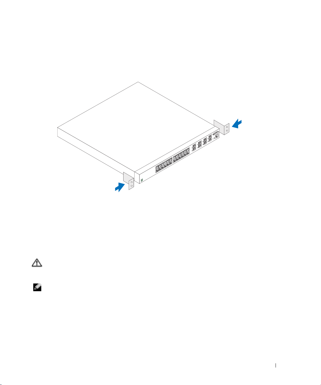
Place the supplied rack-mounting bracket on one side of the device, ensuring that the
mounting holes on the device line up to the mounting holes on the rack-mounting bracket.
Figure 1-1 illustrates where to mount the brackets.
Figure 1-1. Attaching the Brackets
2
Insert the supplied bolts into the rack-mounting holes and tighten with a screwdriver.
3
Repeat the process for the rack-mounting bracket on the other side of the device.
4
Insert the device into the 48.26 cm (19 inch) rack, ensuring that the rack-mounting holes on
the device line up to the mounting holes on the rack.
5
Secure the device to the rack with either the rack bolts or cage nuts and cage nut bolts with
washers (depending on the kind of rack you have). Fasten the bolts on bottom before
fastening the bolts on top. Ensure that the ventilation holes are not obstructed.
CAUTION: Ensure that the supplied rack bolts fit the pre-threaded holes on the rack.
Installing on a Flat Surface (Free-standing Device)
NOTE: We highly recommend that the device be mounted.
Install the device on a flat surface if you are not installing it on a rack. The surface must be able to
support the weight of the device and the device cables. The device is supplied with four
self-adhesive rubber pads.
1
Attach the self-adhesive rubber pads on each location marked on the bottom of the chassis.
2
Set the device on a flat surface, leaving 5.08 cm (2 inches) on each side and 12.7 cm
(5 inches) at the back.
3
Ensure that the device has proper ventilation.
Getting Started Guide 5
Page 8
Connecting a Device to a Power Supply
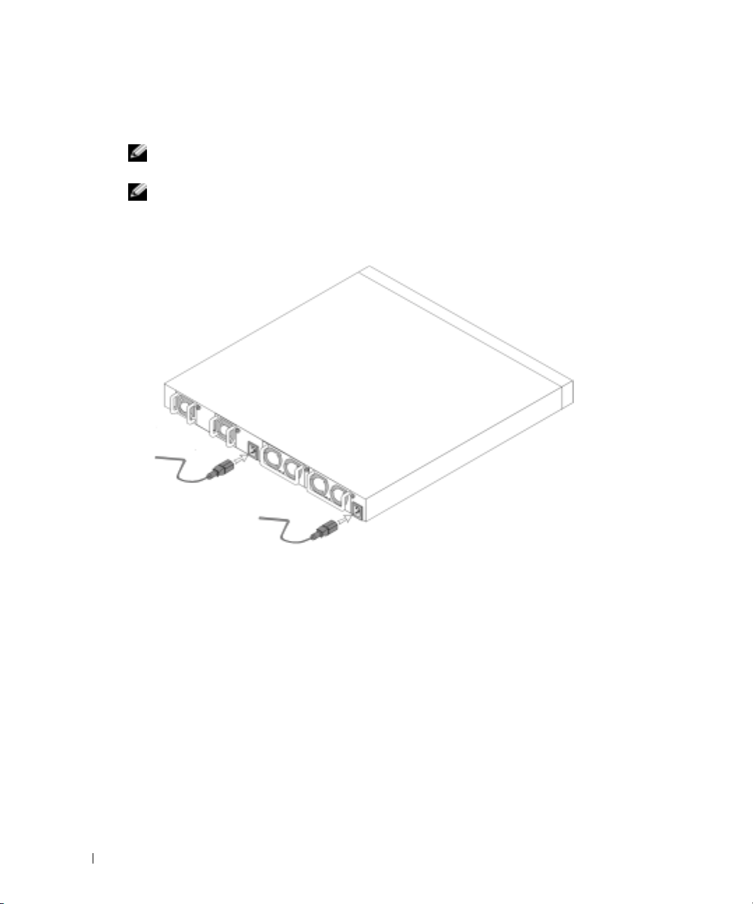
Connect the supplied AC power cable to the AC power connector located on the back panel.
NOTE: Do not connect the power cable to a grounded AC outlet at this time. Connect the device to a
power source as described in the step detailed in “Starting and Configuring the Device."
NOTE: Read the safety information in the Product information Guide as well as the safety information for
other devices that connect to or support the switch.
Figure 1-2. Connecting Power Cable
www.dell.com | support.dell.com
6 Getting Started Guide
Page 9

Starting and Configuring the Device
After completing all external connections, connect a terminal to the device to configure the device.
Additional advanced functions are described in the
User Documentation
NOTE: Read the release notes for this product before proceeding. You can download the release notes
from the Dell Support website at support.dell.com.
NOTE: We recommend that you obtain the most recent version of the user documentation from the Dell
Support website at support.dell.com.
CD.
Connecting the Terminal to the Device
A console port on the device enables you to connect the device to a terminal desktop system
running terminal emulation software; for monitoring and configuring the device. The console port
connector is a male DB-9 connector, implemented as a data terminal equipment (DTE) connector.
To use the console port, the following is required:
• VT100-compatible terminal or a desktop or a portable system with a serial port, running
VT100 terminal emulation software.
• An RS-232 crossover cable with a female DB-9 connector for the console port and the
appropriate connector for the terminal.
Perform the following tasks to connect a terminal to the device console port:
1
Connect an RS-232 crossover cable to the terminal running VT100 terminal emulation software.
2
Configure the terminal emulation software as follows:
a
Select the appropriate serial port (serial port 1 or serial port 2) to connect to the console.
b
Set the data rate to 115200 baud.
c
Set the data format to 8 data bits, 1 stop bit, and no parity.
d
Set the flow control to none.
e
Select
VT100 for Emulation
f
Select Terminal keys for Function, Arrow, and Ctrl keys. Ensure that the setting is for
Terminal keys (not Microsoft
mode under
®
Windows® keys).
User's Guide
Properties
.
located on your
NOTICE: When using HyperTerminal with Microsoft Windows 2000, ensure that you have Windows 2000
Service Pack 2 or later installed. With Windows 2000 Service Pack 2, the arrow keys function properly in
HyperTerminal's VT100 emulation. Go to www.microsoft.com for more information on Windows 2000
service packs.
Connect the female connector of the RS-232 crossover cable directly to the device console
3
port, and tighten the captive retaining bolts. The PowerConnect 6024 and 6024F console
ports are located on the front panel as shown in Figure 1-3.
Getting Started Guide 7
Page 10

Figure 1-3. Connecting to the Console Port
to VT100 terminal device
www.dell.com | support.dell.com
Booting the Device
1
Ensure that the device console port is connected to a VT100 terminal device or VT100
terminal emulator via the RS-232 crossover cable.
2
Locate an AC power receptacle.
3
Deactivate the AC power receptacle.
4
Connect the device to the AC receptacle.
5
Activate the AC power receptacle.
When the power is turned on with the local terminal already connected, the device goes through a
power-on self-test (POST). POST runs every time the device is initialized and checks hardware
components to determine if the device is fully operational before completely booting. If POST
detects a critical problem , the program flow stops. If POST passes successfully, a valid executable
image is loaded into RAM. POST messages are displayed on the terminal and indicate test success
or failure. The boot process runs for approximately 30 seconds.
Initial Configuration
NOTE: The initial simple configuration procedure is based on the following assumptions:
• The PowerConnect device was never configured before and is in the same state as when you
received it.
• The PowerConnect device booted successfully.
• The console connection was established and the console prompt appears on the screen of a
VT100 terminal device.
to console port
8 Getting Started Guide
Page 11

The initial device configuration is performed through the console port. After the initial
configuration, you can manage the device either from the already-connected console port or
remotely through an interface defined during the initial configuration.
NOTE: The device is not configured with a default user name and password.
NOTE: All of the above settings are necessary to allow the remote management of the device through
Telnet (Telnet client) or HTTP (Web browser).
Before setting up the initial configuration of the device, obtain the following information from
your network administrator:
• The IP address to be assigned to the Out-of-Band Ethernet Management Port through which
the device is managed.
• The IP subnet mask for the network
• The IP address of the Out-of-Band Ethernet Management Port default gateway for
configuring the default route.
NOTE: For additional information about the Out-of-Band Ethernet Management Port see the User’s Guide.
Initial Configuration Procedure
You can perform the initial configuration using the Dell PowerConnect Easy Setup Wizard, or by
using the Command Line Interface (CLI). The Setup Wizard automatically starts when the device
configuration file is empty. You can invoke CLI by entering [ctrl+z] anytime during the wizard.
For more information on CLI initial configuration see the
User Guide
. This guide shows how to use
the Setup Wizard for initial device configuration. The Setup Wizard configures the following fields.
• SNMP Community String and SNMP Management System IP address (optional)
• Username and Password
• Out-of-Band Ethernet Management Port IP Address
• Out-of-Band Ethernet Management Port default gateway address
After the device completes the POST and is booted, the following information appears:
Welcome to Dell Easy Setup Wizard
The Setup Wizard guides you through the initial switch
configuration, and gets you up and running easily and quickly.
You can also skip the setup wizard, and enter CLI mode to
manually configure the switch if you prefer.
You can exit the Setup Wizard at any time by entering [ctrl+Z].
The system will prompt you with a default answer; by pressing
enter, you accept the default.
After you configure basic settings using the Setup Wizard, you can
manage the device from the Out-of-band ethernet management port.
Would you like to enter the setup wizard? (Y/N)[Y]
Getting Started Guide 9
Page 12

1
If you enter [N], the Setup Wizard exits. If there is no response within 60 seconds, the
Setup Wizard automatically exits and the CLI console prompt appears. If you enter [Y], the Setup
Wizard provides interactive guidance throughout the initial device configuration.
NOTE: If there is no response within 60 seconds, and there is a BootP server on the network, an address
is retrieved from the BootP server.
NOTE: You can exit the Setup Wizard at any time by entering [ctrl+z].
Wizard Step 1
If you enter [Y] the following information appears:
The system is not setup for SNMP management by default. To
www.dell.com | support.dell.com
manage the switch using SNMP (required for Dell Network
Manager) you can:
•
Setup the initial SNMP version 2 account now.
•
Return later and setup the SNMP version 2 account. (For more
information on setting up a SNMP version 2 account, see the
user documentation).
Would you like to setup the SNMP management interface now?
(Y/N)[Y]
1
Enter [N] to skip to Step 2 or enter [Y] to continue the Setup Wizard. If you enter [Y] the
following information appears:
To setup the SNMP management account you must specify the
management system IP address and the “community string” or
password that the particular management system uses to access
the switch. The wizard automatically assigns the highest access
level [Privilege Level 15] to this account. You can use Dell
Network Manager or other management interfaces to change this
setting later, and to add additional management system later.
For more information on adding management systems, see the user
documentation.
To add a management station:
Please enter the SNMP community string to be
used:[Dell_NetWork_Manager]
2
Enter the following: User SNMP community string, for example "MYSETUPWIZARD".
3
Press
Enter
10 Getting Started Guide
.
Page 13

Wizard Step 2
Please enter the IP address of the Management System (A.B.C.D)
or wildcard (0.0.0.0) to manage from any Management
Station:[0.0.0.0]
1
Enter
– Management System IP address for example “0.0.0.0”, or wildcard mask.
2
Press
Enter
.
Wizard Step 3
The following information appears:
Now we need to setup your initial privilege (Level 15) user
account. This account is used to login to the CLI and Web
interface. You may setup other accounts and change privilege
levels later. For more information on setting up user accounts
and changing privilege levels, see the user documentation.
To setup a user account:
Please enter the user name:
Please enter the user password:
Please reenter the user password:
1
Enter:
– User name, for example “admin”
– Password and password confirmation.
NOTE: If the first and second password entries are not identical, the wizard prompts you to enter
identical passwords.
Press
Enter
Enter
.
.
Getting Started Guide 11
2
3
Enter the password, for example "secret".
4
Press enter.
5
Confirm the password, by entering the identical string, for example, "secret".
6
Press
Page 14

Wizard Step 4
The following information appears:
Next, an IP address is setup. The IP address is defined on the
OOB port. This is the IP address you use to access the CLI, Web
interface, or SNMP interface for the switch.
To setup an IP address:
Please enter the IP address of the device (A.B.C.D):
Please enter the IP subnet mask (A.B.C.D or /nn):
1
Enter the IP address, for example 192.168.1.100.
2
Press
www.dell.com | support.dell.com
3
4
Wizard Step 5
Enter
Enter the IP subnet mask, for example 255.255.255.0
Press
Enter
The following information appears:
Finally, setup the default gateway. Please enter the IP address
of the gateway from which this network is reachable
(for example 192.168.1.1):
1
Enter the default gateway, for example, 192.168.1.1.
2
Press
Enter
The following information appears (as per the example parameters described):
.
.
.
This is the configuration information that has been collected:
SNMP Interface = MYSETUPWIZARD@0.0.0.0
User Account setup = admin
Password = **********
Management IP address = 192.168.1.100 255.255.255.0
Default Gateway = 192.168.1.1
12 Getting Started Guide
Page 15

Wizard Step 6
The following information appears:
If the information is correct, please select (Y) to save the
configuration, and copy to the start-up configuration file.
If the information is incorrect, select (N) to discard
configuration and restart the wizard: [Y/N]
1
Enter [Y] to complete the Setup Wizard or enter [N] to skip to restart the wizard. If you enter [Y]
the following information appears:
Configuring SNMP management interface.
Configuring user account.......
Configuring IP and subnet......
...............................
Thank you for using Dell Easy Setup Wizard. You will now enter
CLI mode.
Wizard Step 7
The CLI prompt appears.
You can now manage the device from the already connected Console port or remotely through
the Out-of-Band Ethernet Management Port interface defined during the initial configuration.
Getting Started Guide 13
Page 16

www.dell.com | support.dell.com
14 Getting Started Guide
Page 17

Systèmes Dell™ PowerConnect™
6024/6024F
Guide de mise en route
www.dell.com | support.dell.com
Page 18
Remarques, avis et précautions
REMARQUE : Une REMARQUE indique des informations importantes qui peuvent vous aider à mieux utiliser votre
ordinateur.
AVIS : Un AVIS vous avertit d’un risque de dommage matériel ou de perte de données et vous indique comment éviter le
problème.
PRÉCAUTION : Une PRÉCAUTION indique un risque potentiel d'endommagement du matériel, de blessure corporelle
ou de mort.
____________________
Les informations contenues dans ce document sont sujettes à modification sans préavis.
© 2004-2005 Dell Inc. Tous droits réservés.
La reproduction de ce document, de quelque manière que ce soit, sans l'autorisation écrite de Dell Inc. est strictement interdite.
Marques utilisées dans ce document : Dell, le logo DELL et PowerConnect sont des marques de Dell Inc. ; Microsoft et Windows sont des
marques déposées de Microsoft Corporation.
D'autres marques et noms commerciaux peuvent être utilisés dans ce document pour faire référence aux entités se réclamant de ces marques
et de ces noms ou à leurs produits. Dell Inc. rejette tout intérêt propriétaire dans les marques et les noms commerciaux autres que les siens.
Modèles 6024 et 6024F
Janvier 2004 Réf. P5028 Rév. A01
Page 19

Installation
Présentation générale
Ce guide présente des informations de base concernant l'installation, la configuration et l'exécution
des systèmes Dell™ PowerConnect™ 6024 et 6024F. Pour en savoir plus, reportez-vous au
d'utilisation
support technique de Dell à l'adresse
documentation et des logiciels.
, qui se trouve sur votre CD
Documentation utilisateur
support.dell.com
pour obtenir les dernières mises à jour de la
ou consultez le site Web de
Préparation du site
Les appareils PowerConnect 60xx peuvent être montés dans un rack standard de 19 pouces (48,26
cm) ou tout simplement être autonomes (placés sur une table). Avant d'installer l'appareil, assurezvous que l'emplacement choisi pour l'installation satisfait aux exigences de site suivantes :
• Alimentation — L'appareil doit être installé près d'une prise électrique facile d'accès de 100 à
250 VCA, 50 à 60 Hz.
• Généralités — Assurez-vous que le bloc d'alimentation est bien installé en vérifiant que les
DEL qui se trouvent sur le panneau avant sont allumées.
• Dégagement — Il doit y avoir assez d'espace pour que l'opérateur puisse accéder à l'appareil.
Assurez-vous de laisser de l'espace pour le câblage, les branchements électriques et la
ventilation.
• Câblage — Le câblage doit être acheminé afin d'éviter les sources d'interférence électrique
comme les transmetteurs radio, les amplificateurs de diffusion, les lignes d'énergie électrique
et les appareils d'éclairage à ampoule fluorescente.
• Environnement — La plage de température ambiante de fonctionnement de l'unité va de 32º
à 131º F (0º à 55º C), à une humidité relative allant jusqu'à 95 pour cent, sans condensation.
Guide
Déballage
Contenu de l'emballage
Pendant le déballage de l'unité, assurez-vous que les articles suivants sont inclus :
• Un appareil PowerConnect
• Deux câbles d'alimentation en CA
• Un câble de jonction RS-232
• Un kit de montage pour une installation sur rack (deux languettes de montage, des boulons et
des écrous à cage)
• Un ensemble de tampons autocollants en caoutchouc destinés à l'appareil installé en
autonome (quatre tampons sont inclus)
•Le CD
• Guide de mise en route
• Le document d'
Documentation utilisateur
Informations sur les réglementations et la sécurité
Guide de mise en route 17
Page 20

Déballage de l'appareil
REMARQUE : Avant de déballer l'appareil, inspectez l'emballage et signalez immédiatement tout signe de
dommage.
Placez le conteneur sur une surface plane et propre et coupez toutes les sangles qui le
1
maintiennent fermé.
2
Ouvrez le conteneur ou retirez la partie supérieure du conteneur.
3
Retirez soigneusement l'appareil du conteneur et placez-le sur une surface stable et propre.
4
Retirez tout le matériel d'emballage.
5
Vérifiez que le produit et ses accessoires ne sont pas endommagés. Signalez immédiatement
tout signe de dommage.
www.dell.com | support.dell.com
Montage du périphérique
Les instructions suivantes s'appliquent aux appareils PowerConnect de série 60xx. Les modèles
PowerConnect 6024 et 6024F sont dotés d'un port console sur le panneau avant.
Les connecteurs d'alimentation de l'appareil se trouvent sur le panneau arrière de celui-ci. Il est
recommandé de connecter les deux blocs d'alimentation remplaçables à chaud.
Installation dans un rack
PRÉCAUTION : N'utilisez pas les kits de montage pour suspendre l'appareil sous une table ou un
bureau ou pour le fixer à un mur.
PRÉCAUTION : Déconnectez tous les câbles de l'appareil avant de continuer. Le cas échéant, retirez
tous les tampons autocollants du dessous de l'appareil.
PRÉCAUTION : Si vous montez plusieurs appareils dans un rack, faites-le en commençant par le bas.
18 Guide de mise en route
Page 21

1
Placez une des languettes métalliques de montage sur rack fournies sur un côté de l'appareil
en vous assurant que les trous de montage de celui-ci s'alignent sur les trous de montage de la
languette métallique de montage sur rack. La Figure 1-1 indique où monter les supports.
Figure 1-1. Fixation des supports
2
Insérez les vis fournies dans les trous de montage sur rack et serrez-les avec un tournevis.
3
Répétez ce processus pour la languette métallique de montage sur rack à installer sur l'autre
côté de l'appareil.
4
Insérez l'appareil dans le rack de 19 pouces (48,26 cm) en vous assurant que les trous de
montage sur rack situés sur l'appareil s'alignent sur les trous de montage du rack.
5
Fixez l'appareil au rack avec les boulons du rack ou des écrous à cage et des boulons d'écrou à
cage avec des rondelles (selon le type du rack dont vous disposez). Attachez les boulons du
bas avant ceux du haut. Assurez-vous que les trous de ventilation ne sont pas obstrués.
PRÉCAUTION : Assurez-vous que les boulons du rack fournis correspondent aux trous pré-percés
dans le rack.
Installation sur une surface plane (Appareil autonome)
REMARQUE : Il est vivement recommandé de monter l'appareil.
L'appareil doit être installé sur une surface plane s'il n'est pas installé dans un rack. La surface doit
pouvoir soutenir le poids du périphérique et de ses câbles. Quatre tampons autocollants en
caoutchouc sont fournis avec l'appareil.
Guide de mise en route 19
Page 22

1
Fixez les tampons autocollants en caoutchouc à chaque endroit marqué, sur la partie
inférieure du châssis.
2
Placez le périphérique sur une surface plane, tout en laissant 2 pouces (5,08 cm) de chaque
côté et 5 pouces (12,7 cm) à l'arrière.
3
Assurez-vous que l'appareil est bien aéré.
Connexion d'un périphérique sur un bloc d'alimentation
Raccordez le câble d'alimentation CA fourni au connecteur d'alimentation CA situé sur le panneau
arrière.
REMARQUE : Ne raccordez pas tout de suite le câble d'alimentation à une prise électrique CA mise à la
www.dell.com | support.dell.com
terre. Connectez l'appareil à une source d'alimentation électrique selon les étapes détaillées à la section
«Mise en route et configuration de l'appareil».
REMARQUE : Lisez les consignes de sécurité du Guide d'information sur le produit ainsi que celles des
périphériques qui se connectent au commutateur ou qui le prennent en charge.
Figure 1-2. Connexion du câble d'alimentation
20 Guide de mise en route
Page 23

Mise en route et configuration de l'appareil
Après avoir effectué toutes les connexions externes, raccordez un terminal à l'appareil afin de
configurer celui-ci. Vous trouverez la description des fonctions avancées supplémentaires dans le
Guide d'utilisation
REMARQUE : Avant de continuer, lisez les notes de mise à jour pertinentes à ce produit. Vous pouvez
télécharger les notes de mise à jour depuis le site Web de support technique de Dell à l'adresse
support.dell.com.
REMARQUE : Nous vous recommandons de vous procurer la révision la plus récente de la
documentation destinée à l'utilisateur depuis le site Web de support technique de Dell à l'adresse
support.dell.com.
Connexion du terminal à l'appareil
Le périphérique contient un port console qui permet une connexion à un terminal de bureau
exécutant un logiciel d'émulation de terminal destiné à la surveillance et à la configuration du
périphérique. Le connecteur de port console est en fait un connecteur DB-9 mâle, qui sert de
connecteur d'équipement de terminal de données (DTE).
Pour utiliser le port console, vous aurez besoin des éléments suivants :
• Un terminal ou un système de bureau ou portatif compatible VT100, doté d'un port série
fonctionnant sous un logiciel d'émulation de terminal VT100
• Un câble de jonction RS-232 doté d'un connecteur DB-9 femelle pour le port console et du
connecteur approprié pour le terminal
Pour connecter un terminal au port console de l'appareil :
1
Raccordez un câble de jonction RS-232 au terminal fonctionnant sous un logiciel d'émulation de
terminal VT100.
2
Configurez le logiciel d'émulation de terminal de la façon suivante :
a
Sélectionnez le port série approprié (port série 1 ou 2) à relier à la console.
b
Configurez le taux de transfert des données à 115200 bauds.
c
Configurez le format de données à 8 bits de données, 1 bit d'arrêt et aucune parité.
d
Configurez le contrôle du flux sur none (aucun).
e
Sous
f
Sélectionnez Touches du terminal pour les touches de fonction, de direction et Ctrl.
Assurez-vous que le paramètre est défini sur Touches du terminal (non pas Touches
Microsoft
qui se trouve sur le CD
Propriétés
, sélectionnez le mode
®
Windows®).
Documentation utilisateur.
VT100 pour émulation
.
Guide de mise en route 21
Page 24

AVIS : Si vous utilisez HyperTerminal avec Microsoft Windows 2000, assurez-vous que le Service Pack 2
de Windows 2000 ou version ultérieure est installé. Lorsque le Service Pack 2 de Windows 2000 est
installé, les touches de direction fonctionnent correctement avec l'émulation VT100 d'HyperTerminal.
Rendez-vous à l'adresse www.microsoft.com pour obtenir des informations sur les services packs de
Windows 2000.
Raccordez le connecteur femelle du câble de jonction RS-232 directement au port console de
3
l'appareil et serrez les boulons de fixation imperdables. Le port console PowerConnect 6024 et
6024F est situé sur le panneau avant, tel qu'illustré à la Figure 1-3.
Figure 1-3. Connexion au port console
www.dell.com | support.dell.com
Amorçage du périphérique
1
Assurez-vous que le port console de l'appareil est connecté à un dispositif terminal VT100 ou
un émulateur de terminal VT100 au moyen du câble de jonction RS-232.
2
Trouvez une prise secteur.
3
Désactivez la prise secteur.
4
Connectez l'appareil à la prise secteur.
5
Activez la prise secteur.
Lorsque l'alimentation fonctionne avec le terminal déjà connecté, l’appareil effectue un auto-test
de mise sous tension (POST). Le POST s'effectue chaque fois que le périphérique est initialisé et
vérifie les composants matériels afin de déterminer si le périphérique fonctionne totalement avant
de poursuivre l'initialisation. Si le POST détecte un problème critique, le flux du programme
s'arrête. Si le POST réussit, une image exécutable valide est chargée dans la mémoire vive (RAM).
Les messages de POST qui s'affichent sur le terminal indiquent la réussite ou l'échec du test. Le
processus d'amorçage dure environ 30 secondes.
vers le dispositif terminal VT100
vers le port console
22 Guide de mise en route
Page 25

Configuration initiale
REMARQUE : Les conditions suivantes doivent être remplies préalablement à la procédure de
configuration initiale :
• L'appareil PowerConnect n'a jamais été configuré auparavant et se trouve dans l'état où vous
l'avez reçu.
• L'amorçage de l'appareil PowerConnect a réussi.
• La connexion à la console est établie et l'invite de la console est affichée sur l'écran d'un
dispositif terminal VT100.
La configuration initiale de l'appareil se fait par l'intermédiaire du port console. Après la
configuration initiale, il est possible de gérer l'appareil depuis le port console déjà connecté ou à
distance au moyen d'une interface qui aura été définie au cours de la configuration initiale.
REMARQUE : L'appareil n'est pas configuré avec un nom d'utilisateur et un mot de passe par défaut.
REMARQUE : Tous les paramètres ci-dessus sont nécessaires pour la gestion à distance de l'appareil
par l'intermédiaire de Telnet (client Telnet) ou HTTP (navigateur Web).
Avant de procéder à la configuration initiale de l'appareil, procurez-vous les informations suivantes
auprès de l'administrateur de réseau :
• L'adresse IP à assigner au port de gestion Ethernet hors bande par lequel l'appareil est géré.
• Le masque de sous-réseau IP pour le réseau
• L'adresse IP de la passerelle par défaut du port de gestion Ethernet hors bande pour
configurer la gamme par défaut.
REMARQUE : Pour en savoir plus sur le port de gestion Ethernet hors bande, reportez-vous au Guide
d'utilisation.
Procédure de configuration initiale
Vous pouvez procéder à la configuration initiale à l'aide de l'Assistant Configuration aisée
PowerConnect de Dell ou de l'Interface de ligne de commande (CLI). l'Assistant Configuration
démarre automatiquement lorsque le fichier de configuration de l'appareil est vide. Vous pouvez
solliciter la CLI en tapant [ctrl+z] à tout moment lorsque l'Assistant est en fonctionnement. Pour
en savoir plus sur la configuration initiale de la CLI, reportez-vous au
Guide d'utilisation
. Ce guide
explique l'utilisation de l'Assistant Configuration pour la configuration initiale de l'appareil.
L'Assistant Configuration configure les champs suivants.
• Chaîne de communauté SNMP et adresse IP du système de gestion SNMP (facultatif)
• Nom d'utilisateur et mot de passe
• Adresse IP du port de gestion Ethernet hors bande
• Adresse de la passerelle par défaut du port de gestion Ethernet hors bande
Guide de mise en route 23
Page 26

Une fois que l'appareil a terminé le POST et est initialisé, les informations suivantes s'affichent :
Welcome to Dell Easy Setup Wizard
The Setup Wizard guides you through the initial switch
configuration, and gets you up and running easily and quickly.
You can also skip the setup wizard, and enter CLI mode to
manually configure the switch if you prefer.
You can exit the Setup Wizard at any time by entering [ctrl+Z].
The system will prompt you with a default answer; by pressing
enter, you accept the default.
After you configure basic settings using the Setup Wizard, you can
www.dell.com | support.dell.com
manage the device from the Out-of-band ethernet management port.
Would you like to enter the setup wizard? (Y/N)[Y]
(
Bienvenue sur l'Assistant Configuration aisée de Dell
L'Assistant Configuration vous guide tout au long de la
configuration initiale du commutateur, et vous permet d'être
rapidement et facilement opérationnel. Vous pouvez également
vous passer de l'Assistant Configuration et entrer en mode CLI
pour configurer le commutateur manuellement si vous le
souhaitez.
Vous pouvez quitter l'Assistant Configuration à tout moment en
tapant [ctrl+Z].
Le système vous propose une réponse par défaut ; vous pouvez
l'accepter en appuyant sur Entrée.
Après avoir configuré les paramètres de base à l'aide de
l'Assistant Configuration, vous pouvez gérer l'appareil à partir
du port de gestion ethernet hors bande.
Souhaitez-vous entrer dans l'Assistant Configuration ? (Y/N)[Y]
(O/N [O])
1
Si vous entrez [N], vous quittez l'Assistant Configuration. Si vous n'entrez pas une réponse
dans les 60 secondes, vous quittez automatiquement l'Assisant Configuration et l'invite de
console CLI s'affiche. Si vous entrez [Y], l'Assistant Configuration fournit des directives
interactives tout au long de la configuration initiale de l'appareil.
)
REMARQUE : Si vous n'entrez pas une réponse dans les 60 secondes, et que le réseau dispose d'un
serveur BootP, une adresse est extraite du serveur BootP.
REMARQUE : Vous pouvez quitter l'Assistant Configuration à tout moment en tapant [ctrl+Z].
24 Guide de mise en route
Page 27

Assistant Étape 1
Si vous entrez [Y], les informations suivantes s'affichent :
The system is not setup for SNMP management by default. To
manage the switch using SNMP (required for Dell Network
Manager) you can:
•
Setup the initial SNMP version 2 account now.
•
Return later and setup the SNMP version 2 account. (For more
information on setting up a SNMP version 2 account, see the
user documentation).
Would you like to setup the SNMP management interface now?
(Y/N)[Y]
(
Le système n'est pas configuré pour la gestion SNMP par
défaut. Pour gérer le commutateur à l'aide de SNMP (requis pour
le gestionnaire de réseau Dell), vous pouvez :
•
Configurer le compte SNMP initial version 2 maintenant.
•
Revenir plus tard pour configurer le compte SNMP version 2.
(Pour en savoir plus sur la configuration du compte SNMP
version 2, reportez-vous à la documentation de l'utilisateur).
Souhaitez-vous configurer l'interface de gestion SNMP
maintenant ? (Y/N)[Y] (O/N [O])
1
Entrez [N] pour sauter l'étape 2 ou entrez [Y] pour poursuivre avec l'Assistant Configuration.
Si vous entrez [Y], les informations suivantes s'affichent :
To setup the SNMP management account you must specify the
management system IP address and the “community string” or
password that the particular management system uses to access
the switch. The wizard automatically assigns the highest access
level [Privilege Level 15] to this account. You can use Dell
Network Manager or other management interfaces to change this
setting later, and to add additional management system later.
For more information on adding management systems, see the user
documentation.
)
To add a management station:
Please enter the SNMP community string to be
used:[Dell_NetWork_Manager]
(
Pour configurer le compte de gestion SNMP, vous devez
spécifier l'adresse IP du système de gestion et la «chaîne
communautaire» ou mot de passe utilisé par ce système de
gestion particulier pour accéder au commutateur. L'Assistant
Guide de mise en route 25
Page 28

assigne automatiquement le plus haut niveau d'accès [Niveau de
privilège 15] à ce compte. Vous pouvez utiliser le gestionnaire
de réseau Dell ou une autre interface de gestion pour modifier
ce paramètre et ajouter un autre système de gestion dans le
futur. Pour en savoir plus sur l'ajout de systèmes de gestion,
reportez-vous à la documentation de l'utilisateur.
Pour ajouter une Management station :
Veuillez saisir la chaîne de communauté SNMP à utiliser :
[Dell_NetWork_Manager] (Gestionnaire de réseau Dell)
2
Tapez ce qui suit : Chaîne de communauté SNMP utilisateur, par exemple
www.dell.com | support.dell.com
«MYSETUPWIZARD».
3
Appuyez sur
Assistant Étape 2
Please enter the IP address of the Management System (A.B.C.D)
or wildcard (0.0.0.0) to manage from any Management
Station:[0.0.0.0]
(
Veuillez entrer l'adresse IP du système de gestion (A.B.C.D)
ou le caractère générique (0.0.0.0) à gérer à partir de
n'importe quelle Management Station :[0.0.0.0]
1
Enter (Entrée)
– Adresse IP du système de gestion, par exemple «0.0.0.0», ou masque de caractère
générique.
2
Appuyez sur
Entrée
Entrée
)
.
)
.
Assistant Étape 3
Les informations suivantes s'affichent :
Now we need to setup your initial privilege (Level 15) user
account. This account is used to login to the CLI and Web
interface. You may setup other accounts and change privilege
levels later. For more information on setting up user accounts
and changing privilege levels, see the user documentation.
To setup a user account:
Please enter the user name:
Please enter the user password:
Please reenter the user password:
26 Guide de mise en route
Page 29

(
Maintenant il faut configurer votre compte utilisateur
privilège initial (Niveau 15). On utilise ce compte pour se
connecter aux interfaces CLI et Web. Vous pouvez configurer
d'autres comptes et modifier les niveaux de privilège plus
tard. Pour en savoir plus sur la configuration des comptes
utilisateur et la modification des niveaux de privilège,
reportez-vous à la documentation de l'utilisateur.
Pour configurer un compte utilisateur :
Veuillez entrer le nom de l'utilisateur :
Veuillez entrer le mot de passe de l'utilisateur :
Veuillez entrer de nouveau le mot de passe de l'utilisateur :
1
Saisissez :
– Nom d'utilisateur, par exemple «admin»
– Mot de passe et confirmation du mot de passe.
REMARQUE : Si le premier et le deuxième mot de passe ne sont pas saisis à l'identique, l'Assistant vous
invite à entrer des mots de passe identiques.
Appuyez sur
2
3
Saisissez le mot de passe, par exemple «secret».
4
Appuyez sur Entrée.
5
Confirmez le mot de passe en entrant une chaîne de caractères identique, par exemple
Entrée
.
«secret».
6
Appuyez sur
Assistant Étape 4
Entrée
.
Les informations suivantes s'affichent :
Next, an IP address is setup. The IP address is defined on the
OOB port. This is the IP address you use to access the CLI, Web
interface, or SNMP interface for the switch.
To setup an IP address:
Please enter the IP address of the device (A.B.C.D):
)
Please enter the IP subnet mask (A.B.C.D or /nn):
(
Ensuite, une adresse IP est configurée. L'adresse IP est
définie sur le port OOB. Cette adresse IP est celle que vous
devez utiliser pour accéder à la CLI, à l'interface Web ou SNMP
du commutateur.
Pour configurer une adresse IP :
Guide de mise en route 27
Page 30

Veuillez entrer l'adresse IP de l'appareil (A.B.C.D) :
Veuillez entrer le masque de sous-réseau IP (A.B.C.D ou /nn) :
1
Entrez l'adresse IP, par exemple 192.168.1.100.
2
Appuyez sur
3
Entrez le masque de sous-réseau IP, par exemple 255.255.255.0
4
Appuyez sur
Assistant Étape 5
Les informations suivantes s'affichent :
www.dell.com | support.dell.com
Finally, setup the default gateway. Please enter the IP address
of the gateway from which this network is reachable
(for example 192.168.1.1):
(
Enfin, configurez la passerelle par défaut. Veuillez entrer
l'adresse IP de la passerelle qui permet l'accès à ce réseau
(par exemple 192.168.1.1):
1
Entrez la passerelle par défaut, par exemple 192.168.1.1.
2
Appuyez sur
Les informations suivantes s'affichent (selon les paramètres utilisés comme exemple) :
This is the configuration information that has been collected:
SNMP Interface = MYSETUPWIZARD@0.0.0.0
User Account setup = admin
Entrée
Entrée
Entrée
)
.
.
)
.
Password = **********
Management IP address = 192.168.1.100 255.255.255.0
Default Gateway = 192.168.1.1
Voici les informations de configuration qui ont été réunies :
(
Interface SNMP = MYSETUPWIZARD@0.0.0.0
Configuration compte utilisateur = admin
Mot de passe = **********
Adresse IP de gestion = 192.168.1.100 255.255.255.0
Passerelle par défaut = 192.168.1.1
28 Guide de mise en route
)
Page 31

Assistant Étape 6
Les informations suivantes s'affichent :
If the information is correct, please select (Y) to save the
configuration, and copy to the start-up configuration file.
If the information is incorrect, select (N) to discard
configuration and restart the wizard: [Y/N]
(
Si les informations sont correctes, veuillez sélectionner (Y)
pour enregistrer la configuration et copier dans le fichier de
configuration de démarrage. Si les informations sont
incorrectes, sélectionnez (N) pour annuler la configuration et
redémarrer l'Assistant : [Y/N] (O/N)
1
Entrez [Y] pour terminer la configuration avec l'Assistant Configuration ou [N] pour redémarrer
)
directement l'Assistant. Si vous entrez [Y], les informations suivantes s'affichent :
Configuring SNMP management interface.
Configuring user account.......
Configuring IP and subnet......
...............................
Thank you for using Dell Easy Setup Wizard. You will now enter
CLI mode.
Configuration interface de gestion SNMP.
(
Configuration compte utilisateur.......
Configuration IP et sous-réseau......
...............................
Merci d'avoir utilisé l'Assistant Configuration aisée de Dell.
Vous entrez maintenant en mode CLI.
Assistant Étape 7
)
L'invite CLI s'affiche.
Il est maintenant possible de gérer l'appareil depuis le port console déjà connecté ou à
distance au moyen de l'interface de port de gestion Ethernet hors bande définie au cours de la
configuration initiale.
Guide de mise en route 29
Page 32

www.dell.com | support.dell.com
30 Guide de mise en route
Page 33

Sistemas Dell™
PowerConnect™ 6024/6024F
Guia de Noções Básicas
www.dell.com | support.dell.com
Page 34

Notas, Avisos e Advertências
NOTA: Indica informações importantes para utilizar melhor o computador.
AVISO: Indica riscos de danos ao hardware ou de perda de dados e lhe diz como evitar o problema.
ADVERTÊNCIA: Indica um potencial de danos ao equipamento, de lesões corporais ou mesmo de morte.
___________________
As informações deste documento estão sujeitas a alteração sem aviso prévio.
© 2004-2005 Dell Inc. Todos os direitos reservados.
Qualquer forma de reprodução deste produto sem a permissão por escrito da Dell Inc. é estritamente proibida.
Marcas comerciais utilizadas neste texto: Dell, o logotipo DELL e PowerConnect são marcas comerciais da Dell Inc.; Microsoft e Windows
são marcas comerciais registradas da Microsoft Corporation.
As demais marcas e nomes comerciais podem ser utilizados neste documento como referência às entidades proprietárias dessas marcas e nomes
ou a seus produtos. A Dell Inc. declara que não tem qualquer interesse de propriedade sobre marcas e nomes comerciais que não sejam os seus
próprios.
Modelos 6024 e 6024F
Janeiro de 2004 P/N P5028 Rev. A01
Page 35

Instalação
Visão geral
Este documento oferece informações básicas para instalar, configurar e operar os sistemas Dell™
PowerConnect 6024 e 6024F. Para obter mais informações, consulte o
encontra disponível no CD contendo a
em
support.dell.com
software.
(em inglês) para obter as atualizações mais recentes da documentação e do
documentação do usuário
Preparação do local
Os dispositivos PowerConnect 60xx podem ser montados em um rack padrão de 48,26 cm ou
podem ser usados -sobre uma bancada. Antes de instalar o dispositivo, verifique se o local escolhido
para a instalação atende aos seguinte requisitos:
• Alimentação — A unidade precisa estar próxima a uma tomada de 100–250 VCA, 50–60 Hz.
• Requisitos gerais — Para saber se a fonte de alimentação está corretamente instalada,
verifique se os LEDs do painel frontal estão acendendo.
• Espaçamento — Verifique se o espaço livre à frente do dispositivo é adequado para o trabalho
do operador. Deixe espaço para o cabeamento, para as conexões de energia e para ventilação.
• Cabeamento — O cabeamento deve ser roteado para evitar fontes de ruído elétrico, como
transmissores de rádio, amplificadores de radiodifusão, linhas de potência e dispositivos de
iluminação fluorescente.
• Requisitos ambientais — A faixa de temperatura ambiente de operação para a unidade é de 0
a 55ºC, com umidade relativa de até 95 %, sem condensação.
Guia do usuário
ou visite o site de suporte da Dell
, que se
Desembalagem
Conteúdo do pacote
Ao desembalar o dispositivo, verifique se os seguintes itens estão presentes:
• Um dispositivo PowerConnect
• Dois cabos de alimentação CA
• Um cabo crossover RS-232
• Um kit de montagem em rack (dois suportes de montagem, parafusos e porcas)
• Um conjunto de pés adesivos de borracha (quatro unidades) para uso do equipamento sobre a
bancada
• CD da
• Guia de Noções Básicas
•
Documentação do usuário
Documento de informações de segurança e normalização
Guia de Noções Básicas 33
Page 36

Como desembalar o dispositivo
NOTE: Antes de desembalar o dispositivo, inspecione a caixa e reporte imediatamente qualquer evidência
de dano.
Coloque a caixa em uma superfície plana e limpa e corte todas as tiras de amarração.
1
2
Abra ou remova a tampa do contêiner .
3
Remova cuidadosamente a unidade e coloque-a numa superfície limpa e segura.
4
Remova todo o material de acondicionamento.
5
Inspecione o produto e os acessórios para certificar-se de que não estejam danificados.
Reporte imediatamente qualquer dano encontrado.
www.dell.com | support.dell.com
Como montar o dispositivo
As instruções a seguir se aplicam aos dispositivos PowerConnect série 60xx. Os sistemas PowerConnect
6024 e 6024F têm a porta console no painel frontal.
Os conectores de alimentação estão no painel traseiro. Recomenda-se que sejam conectadas as
duas fontes de alimentação de troca a quente.
Instalação em um rack
CAUTION: Não use kits de montagem em rack que podem ser usados para pendurar o dispositivo sob
a bancada ou para prendê-lo à parede.
CAUTION: Desconecte todos os cabos do dispositivo antes de continuar. Remova os pés auto-
adesivos da parte inferior do dispositivo, se eles estiverem colados.
CAUTION: Se você for montar vários dispositivos em um rack, comece de baixo para cima.
34 Guia de Noções Básicas
Page 37

1
Coloque o suporte de montagem fornecido em um dos lados do equipamento, alinhando os
orifícios do equipamento com os do suporte. A Figure 1-1 mostra a posição de montagem dos
suportes.
Figure 1-1. Como fixar os suportes de montagem
2
Insira os parafusos fornecidos nos orifícios e aperte-os com uma chave de fenda.
3
Repita o procedimento no suporte do outro lado do dispositivo.
4
Insira o dispositivo no rack de 48,26 cm, alinhando os orifícios dos suportes de montagem
com os orifícios do rack.
5
Prenda o dispositivo ao rack com os parafusos e as porcas. Aperte os parafusos da parte inferior
antes de apertar as porcas na parte superior. Verifique se os orifícios de ventilação não estão
obstruídos.
CAUTION: Verifique se os pinos de metal do rack se encaixam nos orifícios do rack.
Como instalar em uma superfície plana (dispositivo apoiado sobre uma bancada)
NOTE: É altamente recomendável que o dispositivo seja montado.
O dispositivo precisa ser instalado em uma superfície plana, se não for instalado em um rack. A
superfície precisa ser rígida o suficiente para suportar o peso do dispositivo e dos cabos. O
dispositivo é fornecido com quatro pés de borracha auto- adesivos.
1
Cole os pés de borracha auto-adesivos nas posições marcadas na parte inferior do chassi.
2
Coloque o dispositivo em uma superfície plana, deixando vãos de 5 cm de cada lado e de 13
cm na parte de trás.
3
Verifique se o dispositivo tem ventilação adequada.
Guia de Noções Básicas 35
Page 38

Como conectar o dispositivo à fonte de alimentação
Conecte o cabo de alimentação CA fornecido ao conector CA do painel traseiro.
NOTE: Não conecte o plugue à tomada CA ainda. Faça a conexão do dispositivo a uma fonte de energia,
conforme descrito em “Como ligar e configurar o dispositivo."
NOTE: Leia as informações de segurança no guia de informação do produto, bem como as informações
de segurança dos outros dispositivo que podem ser conectados ou que suportam o comutador.
Figure 1-2. Como conectar o cabo de alimentação
www.dell.com | support.dell.com
36 Guia de Noções Básicas
Page 39

Como ligar e configurar o dispositivo
Depois de efetuar todas as conexões externas, conecte um terminal ao dispositivo para configurá-lo.
Funções avançadas adicionais são descritas no
documentação do usuário
NOTE: Antes de continuar, leia as notas de lançamento deste produto. Você pode fazer o download
dessas notas no site de suporte da Dell em support.dell.com (em inglês).
NOTE: Recomendamos que obtenha a versão mais recente da documentação do usuário no site de
suporte da Dell em support.dell.com.
.
Como conectar o terminal ao dispositivo
O dispositivo tem uma porta console que permite a conexão a um computador com um programa
de emulação de terminal para fazer a monitoração e configuração do dispositivo. A porta Console é
um conector DB-9 macho, implementado como conector de DTE (Data Terminal Equipment
[equipamento terminal de dados]).
Para usar a porta Console, você precisará de:
• Um terminal compatível com VT100 ou um sistema portátil ou de desktop com uma porta
serial e um software de emulação do terminal VT100
• Um cabo RS-232 crossover com conector DB-9 fêmea para a porta console e o conector
adequado para o terminal
Para conectar o terminal à porta console do dispositivo, faça o seguinte:
1
Conecte um cabo RS-232 crossover ao sistema que tem o software de emulação do terminal
VT100.
2
Configure o software de emulação de terminal da seguinte maneira:
a
Selecione a porta serial apropriada (porta serial 1 ou porta serial 2) para conectar ao
console.
b
Defina a taxa de dados em 115200 bauds.
c
Defina o formato dos dados como 8 bits de dados, 1 bit de parada, sem paridade.
d
Defina o controle de fluxo como nenhum (none).
e
Selecione o modo
(Propriedades).
f
Selecione Terminal keys (Teclas do terminal) para Function, Arrow, and Ctrl keys (Teclas
de função, de seta e Ctrl). Verifique se a configuração é Terminal keys (Teclas do
terminal), e não Microsoft
VT100 for Emulation
®
Windows® keys (Teclas do Windows).
Guia do usuário
, que se encontra no CD contendo a
(VT100 para emulação) em
Properties
NOTICE: Se estiver usando o HyperTerminal com o Microsoft Windows 2000, você precisará do
Windows 2000 Service Pack 2 ou posterior instalado. Com o Service Pack 2 do Windows 2000, as teclas
de seta funcionam corretamente na emulação do HyperTerminal VT100. Visite o site www.microsoft.com
para obter mais informações sobre os Service Packs do Windows 2000.
Guia de Noções Básicas 37
Page 40

3
Conecte o conector fêmea do cabo crossover RS-232 diretamente à porta console no
comutador e aperte os parafusos de fixação. As portas console do PowerConnect 6024 e do
6024F estão localizadas no painel frontal, conforme mostrado na Figure 1-3.
Figure 1-3. Como fazer a conexão à porta console
www.dell.com | support.dell.com
Como inicializar o dispositivo
1
Verifique se a porta Console está conectada a um terminal VT100, ou a um emulador de
terminal VT100, via cabo RS-232 crossover.
2
Localize o receptáculo do cabo de alimentação CA.
3
Desative o receptáculo da fonte CA.
4
Conecte o dispositivo à tomada CA.
5
Ative o receptáculo da fonte CA.
Quando a alimentação é ligada com o terminal local já conectado, o dispositivo entra no POST
(power-on self-test - teste automático de ativação). O POST é executado toda a vez que o
dispositivo é inicializado e verifica os componentes de hardware para determinar se o dispositivo
está completamente funcional antes da inicialização. Se o POST detectar um problema crítico, o
fluxo do programa pára. Se o POST for executado sem problemas, uma imagem executável válida é
carregada na RAM. As mensagens do POST são mostradas no terminal e indicam os testes bem
sucedidos e malsucedidos. O processo de inicialização demora cerca de 30 segundos.
para o terminal VT100
para a porta console
Configuração inicial
NOTE: O procedimento de configuração inicial se baseia nas seguintes suposições:
• O dispositivo PowerConnect nunca foi configurado antes e está no mesmo estado em que se
encontrava quando você o recebeu.
38 Guia de Noções Básicas
Page 41

• O PowerConnect foi inicializado corretamente.
• A conexão com o console foi estabelecida e o prompt do console aparece na tela de um
terminal VT100.
A configuração inicial é feita através da porta Console. Depois da configuração inicial, o dispositivo
poderá ser gerenciado a partir da porta console já conectada ou remotamente através de uma
interface definida durante a configuração inicial.
NOTE: O dispositivo não está configurado com um nome de usuário e senha padrão.
NOTE: Todas as configurações acima são necessárias para permitir o gerenciamento remoto do
dispositivo por Telnet (cliente Telnet) ou por HTTP (navegador da Web).
Antes de fazer a configuração inicial do dispositivo, obtenha as seguintes informações junto ao
administrador da rede:
• O endereço IP a ser atribuído à porta de gerenciamento Ethernet fora de banda através do
qual o dispositivo é gerenciado.
• A máscara de sub-rede IP para a rede.
• O endereço IP do gateway padrão da porta de gerenciamento Ethernet fora de banda para a
configuração da rota padrão.
NOTE: Para obter informações adicionais sobre a porta de gerenciamento Ethernet fora de banda,
consulte o Guia do usuário.
Procedimento inicial de configuração
Você pode executar a configuração inicial, utilizando o Dell PowerConnect Easy Setup Wizard
(Assistente de configuração fácil do Dell PowerConnect) ou utilizando a interface de linha de
comando (CLI). O Assistente de configuração será iniciado automaticamente quando o arquivo de
configuração do dispositivo estiver vazio. Para se recorrer à interface de linha de comando (CLI),
digite [ctrl+z] a qualquer momento durante a execução do assistente. Para obter mais
informações sobre a configuração inicial na interface de linha de comando (CLI), consulte o
do usuário
. Este guia mostra como usar o Assistente de configuração para fazer a configuração
Guia
inicial do dispositivo. O Assistente de configuração configura os seguintes campos:
• Endereço IP de sistema de gerenciamento SNMP e string de comunidade SNMP (opcional)
• Nome de usuário e senha
• Endereço IP de porta de gerenciamento Ethernet fora de banda
• Endereço do gateway padrão de porta de gerenciamento Ethernet fora de banda
Após o dispositivo terminar o POST e ser reinicializado, as seguintes informações irão aparecer:
Welcome to Dell Easy Setup Wizard
Guia de Noções Básicas 39
Page 42

The Setup Wizard guides you through the initial switch
configuration, and gets you up and running easily and quickly.
You can also skip the setup wizard, and enter CLI mode to
manually configure the switch if you prefer.
You can exit the Setup Wizard at any time by entering [ctrl+Z].
The system will prompt you with a default answer; by pressing
enter, you accept the default.
After you configure basic settings using the Setup Wizard, you can
manage the device from the Out-of-band ethernet management port.
Would you like to enter the setup wizard? (Y/N)[Y]
(
www.dell.com | support.dell.com
Bem-vindo ao Assistente de configuração fácil da Dell
O Assistente de configuração irá orientá-lo durante a
configuração inicial do comutador e fará com que você possa
começar a trabalhar de maneira rápida e fácil. Se preferir,
você pode ignorar o assistente de configuração e entrar no modo
CLI para configurar o comutador manualmente.
Você pode sair do Assistente de configuração a qualquer
momento; para isto basta digitar [ctrl+Z].
O sistema mostrará uma resposta padrão. Para aceitar o padrão,
pressione Enter.
Após configurar os parâmetros básicos usando o Assistente de
configuração, você poderá gerenciar o dispositivo a partir da
porta de gerenciamento Ethernet fora de banda.
Você gostaria de entrar no assistente de configuração?
(S/N)[Y]
1
Se você digitar [N], o Assistente de configuração terminará. Se não for dada uma resposta
dentro de 60 segundos, o Assistente de Configuração terminará automaticamente e o prompt do
console da interface de linha de comando (CLI) aparecerá. Se você digitar [Y], o Assistente de
configuração proporcionará uma orientação interativa durante toda a configuração inicial do
dispositivo.
)
NOTE: Se não for dada uma resposta dentro de 60 segundos e houver um servidor BootP na rede, um
endereço será recuperado do servidor BootP.
NOTE: Você pode sair do Assistente de configuração a qualquer momento ao digitar [ctrl+z].
40 Guia de Noções Básicas
Page 43

Etapa 1 do Assistente
Se você digitar [Y] as seguintes informações aparecerão:
The system is not setup for SNMP management by default. To
manage the switch using SNMP (required for Dell Network
Manager) you can:
•
Setup the initial SNMP version 2 account now.
•
Return later and setup the SNMP version 2 account. (For more
information on setting up a SNMP version 2 account, see the
user documentation).
Would you like to setup the SNMP management interface now?
(Y/N)[Y]
(
Por padrão, o sistema não está configurado para o
gerenciamento SNMP. Para gerenciar o comutador usando o SNMP
(necessário para o gerenciador de redes da Dell) você pode:
•
Configurar agora a conta inicial do SNMP, versão 2.
•
Voltar mais tarde e configurar a conta do SNMP, versão 2. Para
obter mais informações sobre a configuração de uma conta da
versão 2 do SNMP, consulte a documentação do usuário.
Gostaria de configurar agora a interface do gerenciamento SNMP?
(S/N)[Y]
1
Digite [N] para ignorar a etapa 2 ou digite [Y] para continuar a execução do Assistente de
configuração. Se você digitar [Y], as seguintes informações aparecerão:
To setup the SNMP management account you must specify the
management system IP address and the “community string” or
password that the particular management system uses to access
the switch. The wizard automatically assigns the highest access
level [Privilege Level 15] to this account. You can use Dell
Network Manager or other management interfaces to change this
setting later, and to add additional management system later.
For more information on adding management systems, see the user
documentation.
)
To add a management station:
Please enter the SNMP community string to be
used:[Dell_NetWork_Manager]
(
Para configurar a conta do gerenciamento SNMP, você precisa
especificar o endereço IP do sistema de gerenciamento e a
“string de comunidade” ou senha que o sistema de gerenciamento
em particular usa para acessar o comutador. O assistente
Guia de Noções Básicas 41
Page 44

designará automaticamente o nível de acesso mais alto [Nível de
privilégio 15] para essa conta. Você pode usar o gerenciador de
redes da Dell ou outras interfaces de gerenciamento para
posteriormente alterar esta configuração e para adicionar mais
sistemas de gerenciamento. Para obter informações sobre como
adicionar sistemas de gerenciamento, consulte a documentação do
usuário.
Para adicionar uma estação de gerenciamento:
Digite a string de comunidade SNMP a ser
usada:[Dell_NetWork_Manager]
2
www.dell.com | support.dell.com
Digite o seguinte: String de comunidade SNMP do usuário, por exemplo,
"MYSETUPWIZARD".
3
Pressione
Etapa 2 do Assistente
Please enter the IP address of the Management System (A.B.C.D)
or wildcard (0.0.0.0) to manage from any Management
Station:[0.0.0.0]
(
Digite o endereço IP do sistema de gerenciamento (A.B.C.D) ou
curinga (0.0.0.0) para fazer o gerencimento a partir de
qualquer estação de gerenciamento:[0.0.0.0]
1
Digite
– Endereço IP do sistema de gerenciamento, por exemplo, “0.0.0.0” ou máscara de curinga.
2
Pressione
Enter
Enter
)
.
)
.
Etapa 3 do Assistente
As seguintes informações aparecerão:
Now we need to setup your initial privilege (Level 15) user
account. This account is used to login to the CLI and Web
interface. You may setup other accounts and change privilege
levels later. For more information on setting up user accounts
and changing privilege levels, see the user documentation.
To setup a user account:
Please enter the user name:
Please enter the user password:
Please reenter the user password:
42 Guia de Noções Básicas
Page 45

(
Agora precisamos configurar sua conta de usuário inicial com o
nível de privilégio (Nível 15). Esta conta é usada para fazer o
login à interface da Web e à interface de linha de comando
(CLI). Você poderá configurar outras contas e alterar níveis de
privilégio posteriormente. Para obter mais informações sobre
como configurar contas de usuário e alterar níveis de
privilégio, consulte a documentação do usuário.
Para configurar uma conta de usuário:
Digite o nome do usuário:
Digite a senha do usuário:
Digite a senha do usuário novamente:
1
Digite
)
– O nome de usuário, por exemplo, “admin”
– A senha e confirmação da senha.
NOTE: Se a primeira e segunda entradas da senha não forem idênticas, o assistente solicitará que você
digite senhas idênticas.
Pressione
2
3
Digite a senha, por exemplo, "secret".
4
Pressione Enter.
5
Confirme a senha ao digitar a string idêntica, por exemplo, "secret".
6
Pressione
Etapa 4 do Assistente
Enter
Enter
.
.
As seguintes informações aparecerão:
Next, an IP address is setup. The IP address is defined on the
OOB port. This is the IP address you use to access the CLI, Web
interface, or SNMP interface for the switch.
To setup an IP address:
Please enter the IP address of the device (A.B.C.D):
Please enter the IP subnet mask (A.B.C.D or /nn):
Em seguida, será configurado um endereço IP. O endereço IP é
(
definido na porta OOB. Esse é o endereço IP que você usar para
acessar a interface de linha de comando (CLI), interface da Web
ou interface SNMP para o comutador.
Para configurar um endereço IP:
Guia de Noções Básicas 43
Page 46

Digite o endereço IP do dispositivo (A.B.C.D):
Digite a máscara de sub-rede IP (A.B.C.D or /nn):
1
Digite o endereço IP, por exemplo, 192.168.1.100.
2
Pressione
3
Digite a máscara de sub-rede IP, por exemplo, 255.255.255.0
4
Pressione
Etapa 5 do Assistente
As seguintes informações aparecerão:
www.dell.com | support.dell.com
Finally, setup the default gateway. Please enter the IP address
of the gateway from which this network is reachable
(for example 192.168.1.1):
(
Configure o gateway padrão. Digite o endereço IP do gateway a
partir do qual esta rede é acessível(por exemplo 192.168.1.1):
1
Digite o gateway padrão, por exemplo, 192.168.1.1.
2
Pressione
As seguintes informações aparecerão (conforme os parâmetros de exemplo descritos):
This is the configuration information that has been collected:
SNMP Interface = MYSETUPWIZARD@0.0.0.0
User Account setup = admin
Password = **********
Enter
Enter
Enter
)
.
.
)
.
Management IP address = 192.168.1.100 255.255.255.0
Default Gateway = 192.168.1.1
Estas são as informações de configuração que foram coletadas:
(
Interface SNMP = MYSETUPWIZARD@0.0.0.0
Configuração da conta de usuário = admin
Senha = **********
Endereço IP de gerenciamento = 192.168.1.100 255.255.255.0
Gateway padrão = 192.168.1.1
44 Guia de Noções Básicas
)
Page 47

Etapa 6 do Assistente
As seguintes informações aparecerão:
If the information is correct, please select (Y) to save the
configuration, and copy to the start-up configuration file.
If the information is incorrect, select (N) to discard
configuration and restart the wizard: [Y/N]
(
Se as informações estiverem corretas, selecione (S) para
salvar a configuração e copie para o arquivo de configuração de
inicialização. Se as informações estiverem incorretas,
selecione (N) para descartar a configuração e reiniciar o
assistente: [S/N]
1
Digite [Y] para concluir o Assistente de configuração ou digite [N] para reiniciar o assistente. Se
)
você digitar [Y] as seguintes informações aparecerão:
Configurando a interface de gerenciamento SNMP.
Configurando conta de usuário.......
Configurando endereço IP e sub-rede......
...............................
Obrigado por usar o Assistente de configuração fácil da Dell.
Agora você entrará no modo CLI.
Etapa 7 do Assistente
O prompt da interface de linha de comando (CLI) aparecerá.
Agora você poderá gerenciar o dispositivo a partir da já conectada porta Console ou
remotamente através da interface de porta de gerenciamento Ethernet fora de banda definida
durante a configuração inicial.
Guia de Noções Básicas 45
Page 48

www.dell.com | support.dell.com
46 Guia de Noções Básicas
Page 49

Sistemas Dell™ PowerConnect™
6024/6024F
Guía de introducción
www.dell.com | support.dell.com
Page 50

Notas, avisos y precauciones
NOTA: Una NOTA indica información importante que le ayuda a hacer un mejor uso del equipo.
AVISO: Un AVISO indica la posibilidad de daños en el hardware o pérdida de datos, y le explica cómo evitar el problema.
PRECAUCIÓN: Un aviso de PRECAUCIÓN indica el riesgo de daños en la propiedad, lesiones personales o incluso la
muerte.
____________________
La información contenida en este documento puede modificarse sin previo aviso.
© 2004-2005 Dell Inc. Todos los derechos reservados.
La reproducción de este documento de cualquier manera sin la autorización por escrito de Dell Inc.
Marcas comerciales utilizadas en este texto: Dell, el logotipo de DELL y PowerConnect son marcas comerciales de Dell Inc.; Microsoft y
Windows son marcas comerciales registradas de Microsoft Corporation.
En este documento pueden citarse otras marcas y nombres comerciales para referirse a las entidades que los poseen o a sus productos.
Dell Inc. renuncia a cualquier interés sobre la propiedad de marcas y nombres comerciales que no sean los suyos.
Modelos 6024 y 6024F
Enero 2004 N/P P5028 Rev. A01
Page 51

Instalación
Visión general
En este documento se proporciona información básica para instalar, configurar y poner en
funcionamiento los sistemas Dell™ PowerConnect™ 6024 y 6024F. Para obtener más información,
consulte la
sitio web Dell Support en
documentación y el software.
Preparación del emplazamiento
Los dispositivos PowerConnect 60xx se pueden montar en un estante estándar de 48,26 cm (19
pulgadas) o se pueden dejar como dispositivos independientes, es decir, colocados sobre una mesa.
Antes de instalar el dispositivo, asegúrese de que la ubicación de instalación elegida cumple los
siguientes requisitos de emplazamiento:
• Alimentación: el dispositivo está instalado cerca de una toma de alimentación eléctrica de
• General: asegúrese de que el suministro de energía esté correctamente instalado
• Distancia de separación: hay una distancia de separación adecuada en la parte anterior que
• Conexión de cables: la conexión de cables se dispone de tal manera que se eviten fuentes de
• Requisitos ambientales: el intervalo de temperatura ambiente de funcionamiento del
Guía del usuario
100–250 VCA y 50–60 Hz de fácil acceso.
comprobando que los LED del panel anterior estén encendidos.
permite que el operador pueda acceder fácilmente al sistema. Deje una distancia de
separación entre los cables, las conexiones de alimentación y la ventilación.
ruido eléctrico como transmisores de radio, amplificadores de difusión, líneas de alimentación
y accesorios de iluminación fluorescente.
dispositivo es de 0 a 55 °C (de 32 a 131 °F) con una humedad relativa de hasta el 95 por
ciento, sin condensación.
, que está disponible en el CD de
support.dell.com
para obtener las últimas actualizaciones de la
documentación del usuario
, o visite el
Desembalaje
Contenido del paquete
Cuando desembale el paquete, asegúrese de que se incluyen los siguientes elementos:
• Un dispositivo PowerConnect
• Dos cables de alimentación CA
• Un cable cruzado RS-232
• Un estuche de montaje en estante para la instalación de estantes (dos soportes de montaje,
tornillos y tuercas cúbicas)
Guía de introducción 49
Page 52

• Un conjunto de almohadillas de goma autoadhesivas para el dispositivo independiente (se
incluyen cuatro almohadillas)
• CD de
documentación del usuario
• Guía de introducción
• Documento
Desembalaje del dispositivo
NOTA: Antes de desembalar el dispositivo, examine el contenedor e informe inmediatamente de cualquier
daño.
1
Coloque el contenedor en una superficie plana y limpia, y corte todas las correas que fijan el
www.dell.com | support.dell.com
contenedor.
2
Abra el contenedor o extraiga la parte superior del mismo.
3
Con cuidado, extraiga el dispositivo del contenedor y colóquelo en una superficie fija y limpia.
4
Extraiga todos los materiales de embalaje.
5
Compruebe que el producto y los accesorios no estén dañados. Informe inmediatamente de
cualquier daño.
Montaje del dispositivo
Las siguientes instrucciones se refieren a los dispositivos de la serie PowerConnect 60xx. Los dispositivos
PowerConnect 6024 y 6024F tienen el puerto de consola en el panel anterior.
Los conectores de alimentación se encuentran en el panel posterior del dispositivo. Se recomienda
conectar las dos fuentes de alimentación de intercambio dinámico.
Información reglamentaria y de seguridad
Instalación en un estante
PRECAUCIÓN: No utilice los estuches de montaje en estante para colgar el dispositivo debajo de una
mesa o escritorio, ni para fijarlo a una pared.
PRECAUCIÓN: Desconecte todos los cables del dispositivo antes de continuar. Si se han pegado
almohadillas autoadhesivas en la parte inferior del dispositivo, retírelas todas.
PRECAUCIÓN: Cuando se montan varios dispositivos en un estante, se deben montar de abajo hacia
arriba.
50 Guía de introducción
Page 53

1
Coloque el soporte de montaje en estante suministrado en un lateral del dispositivo y
asegúrese de que los agujeros de montaje del dispositivo coinciden con los agujeros de
montaje del soporte de montaje en estante. En la Figura 1-1 se muestra dónde montar los
soportes.
Figura 1-1. Fijación de los soportes
2
Inserte los tornillos suministrados en los agujeros de montaje en estante y ajústelos con un
destornillador.
3
Repita el proceso para el soporte de montaje en estante en el otro lado del dispositivo.
4
Inserte el dispositivo en el estante de 48,26 cm (19 pulgadas) y asegúrese de que los agujeros
de montaje en estante del dispositivo coinciden con los agujeros de montaje del estante.
5
Fije el dispositivo al estante ya sea con los tornillos del estante o las tuercas cúbicas y los
tornillos de tuercas cúbicas con arandelas (en función del tipo de estante que tenga). Apriete
los tornillos de la parte inferior antes de apretarlos en la parte superior. Asegúrese de que los
agujeros de ventilación no están obstruidos.
PRECAUCIÓN: Asegúrese de que los tornillos que se suministran con el estante encajan con los
orificios previamente roscados del estante.
Instalación en una superficie plana (dispositivo independiente)
NOTA: Se recomienda encarecidamente montar el dispositivo.
Instale el dispositivo en una superficie plana si no lo va a instalar en un estante. La superficie debe
poder aguantar el peso del dispositivo y de los cables del mismo. El dispositivo se suministra con
cuatro almohadillas de goma autoadhesivas.
Guía de introducción 51
Page 54

1
Fije las almohadillas de goma autoadhesivas en cada una de las ubicaciones que se señalan en
la parte inferior del chasis.
2
Coloque el dispositivo en una superficie plana y deje 5,08 cm (2 pulgadas) de separación a
ambos lados y 12,7 cm (5 pulgadas) en la parte posterior.
3
Asegúrese de que el dispositivo está correctamente ventilado.
Conexión de un dispositivo a un suministro de energía
Conecte el cable de alimentación CA al conector de alimentación CA que se encuentra en el panel
posterior.
NOTA: Esta vez no conecte el cable de alimentación a una toma de tierra de corriente alterna. Conecte
www.dell.com | support.dell.com
el dispositivo a una fuente de energía tal como se describe en el paso detallado del apartado “Inicio y
configuración del dispositivo”.
NOTA: Lea la información sobre seguridad de la Guía de información del producto así como también la
información sobre seguridad para otros dispositivos que se conectan o son compatibles con el
conmutador.
Figura 1-2. Conexión del cable de alimentación
52 Guía de introducción
Page 55

Inicio y configuración del dispositivo
Después de realizar todas las conexiones externas, conecte un terminal al dispositivo para
configurar el dispositivo. En la
se describen más funciones avanzadas.
usuario
NOTA: Antes de continuar, lea las notas de la versión de este producto. Las notas de la versión se
pueden descargar del sitio web Dell Support en la dirección support.dell.com.
NOTA: Le recomendamos que obtenga la versión más reciente de la documentación del usuario en el
sitio web Dell Support en la dirección support.dell.com.
Conexión del terminal al dispositivo
El dispositivo dispone de un puerto de consola que permite conectar el dispositivo a un sistema de
sobremesa terminal que ejecute software de emulación de terminal para poder supervisarlo y
configurarlo. El conector del puerto de la consola es un conector DB-9 macho, instalado como un
conector DTE (Data Terminal Equipment [Equipo terminal de datos]).
Para utilizar el puerto de la consola, se necesita lo siguiente:
• Un terminal compatible con VT100 o bien un sistema de sobremesa o portátil con un puerto
serie y que ejecuta el software de emulación de terminal VT100.
• Un cable cruzado RS-232 con un conector DB-9 hembra para el puerto de la consola y el
conector adecuado para el terminal.
Realice las siguientes tareas para conectar un terminal al puerto de consola del dispositivo:
1
Conecte un cable cruzado RS-232 al terminal que ejecuta el software de emulación de terminal
VT100.
2
Configure el software de emulación de terminal de la siguiente manera:
a
Seleccione el puerto serie adecuado (puerto serie 1 o puerto serie 2) para conectarlo a la
consola.
b
Configure la frecuencia de datos en 115200 baudios.
c
Configure el formato de los datos en 8 bits de datos, 1 bit de parada y sin paridad.
d
Establezca el control de flujo en ninguno.
e
Seleccione el modo
(Propiedades).
f
Seleccione Terminal keys (Teclas de terminal) para las teclas de función, flecha y control.
Asegúrese de que configura Terminal keys (Teclas de terminal) (no Microsoft
Windows
®
keys [Teclas de Windows]).
Guía del usuario
que se encuentra en el CD de
VT100 for Emulation
documentación del
(VT100 para emulación) en
Properties
®
AVISO: Cuando utilice HyperTerminal con Microsoft® Windows® 2000, asegúrese de que tiene
instalado Windows 2000 Service Pack 2 o posterior. Con Windows 2000 Service Pack 2, las teclas de
flecha funcionan correctamente en la emulación VT100 de HyperTerminal. Vaya a www.microsoft.com
para obtener más información acerca de los Service Packs de Windows 2000.
Guía de introducción 53
Page 56

3
Conecte el conector hembra del cable cruzado RS-232 directamente al puerto de la consola
del dispositivo y apriete los tornillos cautivos de retención. Los puertos de consola de los
dispositivos PowerConnect 6024 y 6024F se encuentran en el panel anterior tal como se
muestra en la Figura 1-3.
Figura 1-3. Conexión del puerto de la consola
www.dell.com | support.dell.com
Inicio del dispositivo
1
Asegúrese de que el puerto de la consola del dispositivo esté conectado a un dispositivo de
terminal VT100 o a un emulador de terminal VT100 mediante el cable cruzado RS-232.
2
Localice un enchufe de CA.
3
Desactive el enchufe de CA.
4
Conecte el dispositivo al enchufe de CA.
5
Active el enchufe de CA.
Si se enciende la alimentación con el terminal local ya conectado, el dispositivo pasa por una
autoprueba de encendido (POST). POST se ejecuta cada vez que el dispositivo se inicia y
comprueba los componentes de hardware para determinar si el dispositivo está completamente
operativo antes de iniciarse por completo. Si la POST detecta un problema grave, el flujo del
programa se detiene. Si POST se pasa correctamente, se carga una imagen ejecutable válida en la
RAM. Los mensajes de POST se muestran en el terminal e indican si la prueba ha finalizado con
éxito o no. El proceso de inicio dura aproximadamente 30 segundos.
al dispositivo de terminal VT100
al puerto de la consola
54 Guía de introducción
Page 57

Configuración inicial
NOTA: El procedimiento de configuración sencilla inicial se basa en los siguientes supuestos:
• El dispositivo PowerConnect no se ha configurado antes y se encuentra en el mismo estado
que cuando lo recibió.
• El dispositivo PowerConnect se ha iniciado correctamente.
• Se ha establecido la conexión de la consola y la petición de consola aparece en la pantalla de
un dispositivo de terminal VT100.
La configuración inicial del dispositivo se realiza mediante el puerto de la consola. Después de la
configuración inicial, el dispositivo se puede gestionar desde el puerto de la consola ya conectado o
de manera remota mediante una interfaz definida durante la configuración inicial.
NOTA: El dispositivo no se configura con un nombre de usuario y una contraseña predeterminados.
NOTA: Todos los valores anteriores son necesarios para poder gestionar el dispositivo de manera
remota mediante Telnet (cliente Telnet) o HTTP (explorador de la web).
Antes de establecer la configuración inicial del dispositivo, se debe obtener la siguiente información
del administrador de red:
• La dirección IP que se le asignará al puerto de gestión Ethernet fuera de banda a través del
cual se gestiona el dispositivo.
• La máscara de subred IP de la red
• La dirección IP de la puerta de enlace predeterminada del puerto de gestión Ethernet fuera de
banda para configurar la ruta predeterminada.
NOTA: Para obtener información adicional sobre el puerto de gestión Ethernet fuera de banda, consulte
la Guía del usuario.
Procedimiento de configuración inicial
Puede realizar la configuración inicial mediante el asistente para la instalación sencilla de Dell
PowerConnect o mediante la interfaz de línea de comandos (CLI). El asistente para la instalación
se inicia automáticamente cuando el archivo de configuración del dispositivo está vacío. Puede
invocar la CLI si pulsa [ctrl+z] en cualquier momento durante la ejecución del asistente. Para
obtener más información sobre la configuración inicial de la CLI, consulte la
Guía del usuario
. En
esta guía se muestra cómo utilizar el asistente para la instalación para realizar la configuración
inicial del dispositivo. El asistente para la instalación configura los campos siguientes.
• Cadena de comunidad SNMP y dirección IP del sistema de gestión SNMP (opcional)
• Nombre de usuario y contraseña
• Dirección IP del puerto de gestión Ethernet fuera de banda
• Dirección de la puerta de enlace predeterminada del puerto de gestión Ethernet fuera de
banda
Guía de introducción 55
Page 58

Después de que el dispositivo haya completado la POST y se haya iniciado, aparece la siguiente
información:
Welcome to Dell Easy Setup Wizard
The Setup Wizard guides you through the initial switch
configuration, and gets you up and running easily and quickly.
You can also skip the setup wizard, and enter CLI mode to
manually configure the switch if you prefer.
You can exit the Setup Wizard at any time by entering [ctrl+Z].
The system will prompt you with a default answer; by pressing
enter, you accept the default.
www.dell.com | support.dell.com
After you configure basic settings using the Setup Wizard, you can
manage the device from the Out-of-band ethernet management
port.
Would you like to enter the setup wizard? (Y/N)[Y]
(
Bienvenido al Asistente para la instalación fácil de Dell
El Asistente para la instalación le muestra los pasos de la
configuración inicial del conmutador y le permite empezar a
trabajar de manera fácil y rápida.
También puede omitir el Asistente para la instalación y entrar
en el modo CLI para configurar el conmutador manualmente si lo
desea.
Puede salir del Asistente para la instalación en cualquier
momento pulsando [ctrl+Z]. El sistema le solicitará una
respuesta predeterminada; si pulsa Intro, aceptará el valor
predeterminado.
Después de configurar los parámetros básicos mediante el
Asistente para la instalación, podrá gestionar el dispositivo
desde el puerto de gestión Ethernet fuera de banda.¿Desea
entrar en el asistente para la instalación?(S/N [S]
1
Si escribe [N], saldrá del asistente para la instalación. Si no responde antes de 60 segundos,
saldrá automáticamente del asistente para la instalación y aparecerá el símbolo de consola de la
CLI. Si escribe [Y], el asistente para la instalación le guiará de manera interactiva por todo el
proceso de configuración inicial del dispositivo.
))
NOTA: Si no hay ninguna respuesta antes de 60 segundos, y hay un servidor BootP en la red, se
recuperará una dirección del servidor BootP.
NOTA: Puede salir del asistente para la instalación en cualquier momento pulsando [Ctrl+z].
56 Guía de introducción
Page 59

Paso 1 del Asistente
Si escribe [Y] aparece la siguiente información:
The system is not setup for SNMP management by default. To
manage the switch using SNMP (required for Dell Network
Manager) you can:
•
Setup the initial SNMP version 2 account now.
•
Return later and setup the SNMP version 2 account. (For more
information on setting up a SNMP version 2 account, see the
user documentation).
Would you like to setup the SNMP management interface now?
(Y/N)[Y]
(
El sistema no está configurado de manera predeterminada para
la gestión SNMP. Para gestionar el conmutador con SNMP
(obligatorio para Dell Network Manager) puede:
•
Configurar ahora la cuenta inicial de SNMP versión 2.
•
Volver después y configurar la cuenta de SNMP versión 2. (Para
obtener más información sobre la configuración de una cuenta
de SNMP versión 2, consulte la documentación del usuario).
¿Desea configurar ahora la interfaz de gestión SNMP?(S/N [S])
1
Escriba [N] para pasar al paso 2 o [Y] para continuar con el Asistente para la instalación. Si
escribe [Y] aparece la siguiente información:
To setup the SNMP management account you must specify the
management system IP address and the "community string" or
password that the particular management system uses to access
the switch. The wizard automatically assigns the highest access
level [Privilege Level 15] to this account. You can use Dell
Network Manager or other management interfaces to change this
setting later, and to add additional management system later.
For more information on adding management systems, see the user
documentation.
)
To add a management station:
Please enter the SNMP community string to be
used:[Dell_NetWork_Manager]
(
Para configurar la cuenta de gestión SNMP debe especificar la
dirección IP del sistema de gestión y la “cadena de comunidad”
o contraseña que el sistema de gestión en concreto utiliza para
acceder al conmutador. El asistente asigna automáticamente el
nivel de acceso más alto [Nivel de privilegio 15] a esta
Guía de introducción 57
Page 60

cuenta. Puede utilizar Dell Network Manager u otras interfaces
de gestión para modificar este valor más tarde así como para
agregar un sistema de gestión adicional posteriormente. Si
desea obtener más información sobre cómo agregar sistemas de
gestión, consulte la documentación del usuario.
Para agregar una estación de gestión:
Introduzca la cadena de comunidad SNMP que se utilizará:
[Dell_NetWork_Manager]
2
Escriba lo siguiente: Cadena de comunidad SNMP del usuario, por ejemplo
“MYSETUPWIZARD”.
www.dell.com | support.dell.com
3
Pulse
Intro
Paso 2 del Asistente
Please enter the IP address of the Management System (A.B.C.D)
or wildcard (0.0.0.0) to manage from any Management
Station:[0.0.0.0]
(
Introduzca la dirección IP del sistema de gestión (A.B.C.D) o
comodín (0.0.0.0) para gestionar desde cualquier estación de
gestión:[0.0.0.0]
1
Introduzca
– La dirección IP del sistema de gestión como, por ejemplo, “0.0.0.0”, o una máscara
comodín.
2
Pulse
Intro
)
.
)
.
Paso 3 del Asistente
Aparece la siguiente información:
Now we need to setup your initial privilege (Level 15) user
account. This account is used to login to the CLI and Web
interface. You may setup other accounts and change privilege
levels later. For more information on setting up user accounts
and changing privilege levels, see the user documentation.
To setup a user account:
Please enter the user name:
Please enter the user password:
Please reenter the user password:
58 Guía de introducción
Page 61

(
Ahora es necesario configurar su cuenta de usuario de
privilegio inicial (Nivel 15). Esta cuenta se utiliza para
iniciar la sesión de la CLI y la interfaz web. Podrá configurar
otras cuentas y cambiar los niveles de privilegio más tarde. Si
desea obtener más información sobre la configuración de las
cuentas de usuario y la modificación de los niveles de
privilegio, consulte la documentación del usuario.
Para configurar una cuenta de usuario:
Introduzca el nombre del usuario:
Introduzca la contraseña del usuario:
Vuelva a introducir la contraseña del usuario:
1
Introduzca:
)
– Nombre de usuario, por ejemplo “admin”
– Contraseña y confirmación de la contraseña.
NOTA: Si la primera y la segunda entrada de la contraseña no son idénticas, el asistente le pide que
introduzca contraseñas idénticas.
Pulse
Intro
Intro
.
.
2
3
Introduzca la contraseña, por ejemplo “secret”.
4
Pulse Intro.
5
Confirme la contraseña, introduciendo la cadena idéntica, por ejemplo, “secret”.
6
Pulse
Paso 4 del Asistente
Aparece la siguiente información:
Next, an IP address is setup. The IP address is defined on the
OOB port. This is the IP address you use to access the CLI, Web
interface, or SNMP interface for the switch.
To setup an IP address:
Please enter the IP address of the device (A.B.C.D):
Please enter the IP subnet mask (A.B.C.D or /nn):
(
A continuación, se configura una dirección IP. La dirección IP
se define en el puerto OOB. Ésta es la dirección IP que se
utiliza para acceder a la CLI, la interfaz web o la interfaz
SNMP del conmutador.
Para configurar una dirección IP:
Guía de introducción 59
Page 62

Introduzca la dirección IP del dispositivo (A.B.C.D):
Introduzca la máscara de subred IP (A.B.C.D o /nn):
1
Introduzca la dirección IP, por ejemplo 192.168.1.100.
2
Pulse
Intro
3
Introduzca la máscara de subred IP, por ejemplo 255.255.255.0
4
Pulse
Intro
Paso 5 del Asistente
Aparece la siguiente información:
www.dell.com | support.dell.com
Finally, setup the default gateway. Please enter the IP address
of the gateway from which this network is reachable
(for example 192.168.1.1):
(
Por último, configure la puerta de enlace predeterminada.
Introduzca la dirección IP de la puerta de enlace desde la que
se puede acceder a esta red (por ejemplo 192.168.1.1):
1
Introduzca la puerta de enlace predeterminada, por ejemplo, 192.168.1.1.
2
Pulse
Intro
Aparece la siguiente información (según los parámetros descritos en el ejemplo):
This is the configuration information that has been collected:
SNMP Interface = MYSETUPWIZARD@0.0.0.0
User Account setup = admin
)
.
.
)
.
Password = **********
Management IP address = 192.168.1.100 255.255.255.0
Default Gateway = 192.168.1.1
(
Ésta es la información de configuración que se ha recopilado:
Interfaz SNMP = MYSETUPWIZARD@0.0.0.0
Configuración de la cuenta de usuario = admin
Contraseña = **********
Dirección IP de gestión = 192.168.1.100 255.255.255.0
Puerta de enlace predeterminada = 192.168.1.1
60 Guía de introducción
)
Page 63

Paso 6 del Asistente
Aparece la siguiente información:
If the information is correct, please select (Y) to save the
configuration, and copy to the start-up configuration file.
If the information is incorrect, select (N) to discard
configuration and restart the wizard: [Y/N]
(
Si la información es correcta, seleccione (S) para guardar la
configuración y copiarla en el archivo de configuración de
inicio. Si la información no es correcta, seleccione (N) para
rechazar la configuración y reiniciar el asistente: [S/N]
1
Escriba [Y] para completar el asistente para la instalación o [N] para omitir el reinicio del
asistente. Si escribe [Y] aparecerá la siguiente información:
Configuring SNMP management interface.
Configuring user account.......
Configuring IP and subnet......
...............................
Thank you for using Dell Easy Setup Wizard. You will now enter
CLI mode.
Configurando la interfaz de gestión SNMP.
(
Configurando la cuenta de usuario.......
)
Configurando IP y la subred......
...............................
Gracias por utilizar el Asistente para la instalación fácil de
Dell. Ahora entrará en el modo CLI
Paso 7 del Asistente
.)
Aparece el símbolo de la CLI.
Ahora puede gestionar el dispositivo desde el puerto de consola ya conectado o remotamente
a través de la interfaz del puerto de gestión Ethernet fuera de banda durante la configuración
inicial.
Guía de introducción 61
Page 64

www.dell.com | support.dell.com
62 Guía de introducción
Page 65

Page 66

Printed in China.
Imprimé en Chine.
Impresso nos China
Impreso en China.
Printed on Recycled Paper
.
.
 Loading...