

Page 1

Dell PowerConnect
RPS720, MPS600, MPS1000,
and MPS 1U Shelf
Getting Started
With Your System
Regulatory Model PowerConnect RPS720,
MPS600, and MPS1000
Page 2

Notes, Cautions, and Warnings
NOTE:
A NOTE indicates important information that helps you make better use of
your computer.
CAUTION:
instructions are not followed.
WARNING:
injury, or death.
A CAUTION indicates potential damage to hardware or loss of data if
A WARNING indicates a potential for property damage, personal
____________________
Information in this publication is subject to change without notice.
© 2010 Dell Inc. All rights reserved.
Reproduction of these materials in any manner whatsoever without the written permission of Dell Inc.
is strictly forbidden.
Trademarks used in this text: Dell™, the DELL logo, and PowerConnect™ are trademarks of Dell
Inc. EMC
Other trademarks and trade names may be used in this publication to refer to either the entities claiming
the marks and names or their products. Dell Inc. disclaims any proprietary interest in trademarks and
trade names other than its own.
Regulatory Model PowerConnect RPS720, MPS600, and MPS1000
November 2010 P/N KPCT8 Rev. A00
®
is a registered trademark of EMC Corporation.
Page 3
Features
Dell PowerConnect RPS720
Figure 1-1. Front Panel Indicators-PowerConnect RPS720
• Supports up to four PowerConnect switches through 12 V DC output
• Dedicated 180 W power supply for up to four connected switches
• Front panel LEDs display status of individual power supplies
• 1U, 19-inch rack mountable system
NOTE:
The PowerConnect RPS720 redundant power bank provides four external
redundant power supplies for your PowerConnect switches, eliminating the power
supply as a single point of failure.
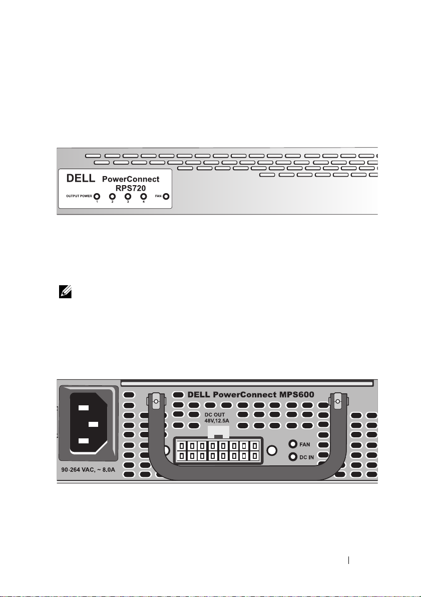
Dell PowerConnect MPS600
Figure 1-2. Front Panel Indicators-PowerConnect MPS600
• Supports one PowerConnect 55xxP (PoE) switch through 48 V DC output
• Dedicated 600 W power supply for one connected switch
• Front panel LEDs display status of the power supply
Getting Started With Your System
3
Page 4
• 1U, 19-inch rack mountable system with brackets
• Up to three MPS600 units in a MPS 1U Shelf (density–3per 1U, 19-inch rack)
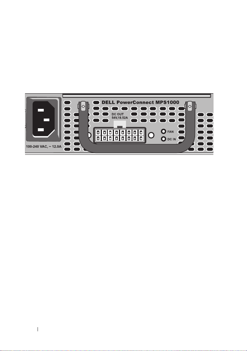
Dell PowerConnect MPS1000
Figure 1-3. Front Panel Indicators–PowerConnect MPS1000
• Supports one PowerConnect 70xxP (PoE+) switch through 54 V DC output
• Dedicated 1000 W power supply for one connected switch
• Front panel LEDs display status of the power supply
• 1U, 19-inch rack mountable system with brackets
• Up to three MPS1000 units in a MPS 1U Shelf (density–3 per 1U,
19-inch rack)
Unpacking
Package Contents
Before you install the RPS720, MPS600, MPS1000, or MPS 1U Shelf, verify
your package contents for:
• One of the following units:
– RPS720—Redundant power bank (supports up to four switches)
– MPS600—Modular power supply 600 watts
– MPS1000—Modular power supply 1000 watts
– MPS 1U Shelf—Mechanical shelf holds up to three MPS600,
MPS1000, or a combination
4
Getting Started With Your System
Page 5
• Rack mounting kit
• AC power cord:
– RPS720—Type C13 plug
– MPS600—Type C13 plug
– MPS1000—Type C15 plug (with notch)
• Switch DC power cords:
– RPS720—14-pin DC power cords (4)
– MPS600—16-pin DC power cord (1)
– MPS1000—16-pin DC power cord (1)
Installation
WARNING:
instructions that came with the system.
CAUTION:
consult your PowerConnect Switch User's Guide to confirm that your switch
supports the PowerConnect RPS720 redundant power bank or the
MPS600/MPS1000 external power supply.
PowerConnect RPS720
Installing PowerConnect RPS720 on a Flat Surface
You can install the PowerConnect RPS720 on any appropriate level surface
that can safely support the weight of the switches, the PowerConnect
RPS720, and their attached cables. There must be adequate space around
the PowerConnect RPS720 for ventilation and to access cable connectors.
Before performing the following procedure, review the safety
Before you install the PowerConnect RPS720, MPS600, or MPS1000,
CAUTION:
and 5 inches (12.7 cm) at the back for power cord clearance.
1
Set the RPS720 on a flat surface and check for proper ventilation.
2
Attach rubber feet (optional) on each marked location at the bottom of
Allow at least 2 inches (5.1 cm) on each side for proper ventilation
the chassis.
NOTE:
Although optional, rubber feet are recommended to keep the unit
from slipping.
Getting Started With Your System
5
Page 6

Installing PowerConnect RPS720 in a Rack
The PowerConnect RPS720 can be installed in most standard 19-inch racks.
NOTE:
For racks that are not pre-threaded, cage nuts are provided.
Figure 1-4. Attaching Mounting Brackets–PowerConnect RPS720
3
Use the screws that are provided to attach a mounting bracket to each
side of the
4
Position the
PowerConnect
PowerConnect
RPS720.
RPS720 in the rack and align the holes in
the mounting bracket with the holes in the rack.
5
Insert and tighten two screws through each of the mounting brackets.
6
Getting Started With Your System
Page 7

Operating the PowerConnect RPS720 After Installation
1
Plug one end of the switch DC power cord (14-pin) into the connector
labeled
RPS
on the back of the switch. Connect the other end of the
switch DC power cord to any available RPS connector on the back of
the
PowerConnect
Figure 1-5. Back View–PowerConnect RPS720
2
Attach the AC power cord to the
RPS720.
PowerConnect
RPS720 and to
an AC power outlet.
The switch is now using both power supplies simultaneously. You can
monitor the status of the two power supplies through the front panel
LEDs on your PowerConnect switch and the
PowerConnect
RPS720.
PowerConnect MPS600 or MPS1000
Installing PowerConnect MPS600 or MPS1000 on a Flat Surface
You can install the PowerConnect MPS600 or MPS1000 on any appropriate
level surface that can safely support the weight of the switch,
the PowerConnect MPS600 or MPS1000, and their attached cables.
There must be adequate space around the PowerConnect MPS600 or
MPS1000 for ventilation and to access cable connectors.
CAUTION:
5 inches (12.7 cm) at the back for power cord clearance.
1
Set the
Allow at least 2 inches (5.1 cm) on each side for proper ventilation and
PowerConnect
MPS600 or MPS1000 on the flat surface and check
for proper ventilation.
2
Attach rubber feet (optional) on each marked location at the bottom of
the chassis.
NOTE:
Although optional, rubber feet are recommended to keep the unit
from slipping.
Getting Started With Your System
7
Page 8

Installing PowerConnect MPS600 or MPS1000 in a Rack
The PowerConnect MPS600 or MPS1000 can be installed in most standard
19-inch racks.
NOTE:
For racks that are not pre-threaded, cage nuts are provided.
Figure 1-6. Attaching Mounting Brackets–PowerConnect MPS600 or MPS1000
3
Use the screws that are provided to attach a mounting bracket to each side
of the
4
Position the
PowerConnect
PowerConnect
MPS600 or MPS1000.
MPS600 or MPS1000 in the rack and align the
holes in the mounting bracket with the holes in the rack.
5
Insert and tighten two screws through each of the mounting brackets.
8
Getting Started With Your System
Page 9

Operating the PowerConnect MPS600 or MPS1000 After Installation
1
Plug one end of the switch DC power cord (16-pin) into the connector
labeled
MPS
on the back of the switch. Connect the other end of the
switch DC power cord to the DC OUT connector on the back of the
PowerConnect MPS600 or MPS1000.
Figure 1-7. Back View–PowerConnect
2
Attach the AC power cord to the MPS600 or MPS1000 and to
MPS600/MPS1000
an AC power outlet.
The switch is now using both power supplies simultaneously. You can
monitor the status of the two power supplies through the front panel
LEDs on your PowerConnect switch and the MPS600 or MPS1000.
PowerConnect MPS 1U Shelf
Installing PowerConnect MPS 1U Shelf on a Flat Surface
You can install the PowerConnect MPS 1U Shelf on any appropriate level
surface that can safely support the weight of up to three switches, up to three
PowerConnect MPS600 or MPS1000, and their attached cables. There must
be adequate space around the PowerConnect MPS 1U Shelf for ventilation
and to access cable connectors.
CAUTION:
and 5 inches (12.7 cm) at the back for power cord clearance.
1
Set the
proper ventilation.
2
Attach rubber feet (optional) on each marked location at the bottom of
the chassis.
Allow at least 2 inches (5.1 cm) on each side for proper ventilation
PowerConnect
MPS 1U Shelf on the flat surface and check for
NOTE:
Although optional, rubber feet are recommended to keep the unit
from slipping.
Getting Started With Your System
9
Page 10

Installing PowerConnect MPS 1U Shelf in a Rack
The PowerConnect MPS 1U Shelf can be installed in most standard
19-inch racks.
NOTE:
For racks that are not pre-threaded, cage nuts are provided.
1
Use the screws that are provided to attach a mounting bracket to each side
of the
2
Position the
PowerConnect
PowerConnect
MPS 1U Shelf.
MPS 1U Shelf in the rack and align the holes
in the mounting bracket with the holes in the rack.
3
Insert and tighten two screws through each of the mounting brackets.
Operating the PowerConnect MPS600 or MPS1000 in the MPS 1U Shelf After
Installation
1
Install up to three
PowerConnect
MPS600 or MPS1000 (or combinations)
into the MPS 1U Shelf.
Figure 1-8. Back View–PowerConnect MPS 1U Shelf
2
Plug one end of the switch DC power cord (16-pin) into the connector
labeled
the switch DC power cord to the
available
3
Attach the AC power cord to the
MPS
on the back of an available switch. Connect the other end of
PowerConnect
DC OUT
MPS600 or MPS1000.
PowerConnect
connector on the back of an
MPS600 or MPS1000 and
to an AC power outlet.
The switches are now using both power supplies simultaneously. You can
monitor the status of the all the power supplies through the front panel
LEDs on your PowerConnect switches and the
PowerConnect
MPS600s
or MPS1000s.
10
Getting Started With Your System
Page 11

Other Information You May Need
WARNING:
your system. Warranty information may be included within this document or
as a separate document.
• The rack documentation included with your rack solution describes
how to install your system into a rack.
• The PowerConnect Switch User Guides
features and describes how to troubleshoot the system and install or
replace system components. These documents are available online at
support.dell.com/manuals
See the safety and regulatory information that shipped with
provide information about system
.
NOTE:
Always check for updates on support.dell.com/manuals and read the
updates first because they often supersede information in other documents.
Obtaining Technical Assistance
If you need help with a technical problem, see the Dell Support website at
support.dell.com for the latest updates on documentation and firmware.
Technical Specifications
PowerConnect RPS720
The PowerConnect RPS720 contains four independent 180 W power
supplies.
Physical
Height 43.2 mm (1.7 in)
Width 440 mm (17.32 in)
Depth 257 mm (10.18 in)
Getting Started With Your System
11
Page 12

180 W AC-DC power supply
NOTE:
The power supply has an universal input (90 VAC to 264 VAC) and a 12 VDC
regulated output. This regulated output supplies power to other power supply backup
source. The power supply incorporates over current protection and OVP.
Input Voltage Universal input– 90 to 264 VAC
Nominal input– 15 to 230 VAC.
Input Frequency Range 47 to 63 Hz
Max. Input AC Current 2.3 A max per supply
(9.2 A total for four supplies in
PowerConnect RPS720)
Output Voltage and Current
Parameter
Nominal Output Voltage
Absolute Maximum Tolerance
Output Ripple Voltage
Minimum Current
Maximum Current
DC FAN Specification
Bearing Type Two-ball bearing
Rated Voltage 12 V DC
Operating Voltage Range 7.0 V–13.8 V
Speed (Reference Value) 9000 RPM
Air Delivery 10.10 CFM
Noise 32.5dB
Operating Temperature -20 to +70 ºC
Storage Temperature -40 to +70 ºC
12 V output unit
+12 V
+/- 5 %
500 mV pk-pk
0.0 A
15 A
12
Getting Started With Your System
Page 13

PowerConnect MPS600
The PowerConnect MPS600 contains a 600 W power supply.
Physical
Height 41.6 mm (1.64 in)
Width 133.8 mm (5.27 in)
Depth 401.4 mm (15.8 in)
600 W AC-DC power supply
NOTE:
The power supply has an universal input (90 VAC to 264 VAC) and a 12 VDC
regulated output. This regulated output supplies power to other power supply backup
source. The power supply incorporates over current protection and OVP.
Input Voltage Universal input– 90 to 264 VAC
Input Frequency Range 47 to 63 Hz, single phase AC
Max. Input AC Current 8.0 A (maximum)
Output Voltage and Current
No of Output
Nominal Output Voltage Set Point
Set Point Tolerance
Total Error Band
Minimum Current
Maximum Current
1
48 V DC
+/- 1%
+/- 2%
1.0 A
12.5 A
(maximum)
(maximum)
(maximum)
PowerConnect MPS1000
The PowerConnect MPS1000 contains a 1000 W power supply.
Physical
Height 41.6 mm (1.64 in)
Width 133.8 mm (5.27 in)
Depth 401.4 mm (15.8 in)
Getting Started With Your System
(maximum)
(maximum)
(maximum)
13
Page 14

1000 W AC-DC power supply
NOTE:
The power supply has an universal input (100 VAC to 240 VAC). This regulated
output supplies power to other power supply backup source. The power supply
incorporates over current protection and OVP.
Input Voltage Universal input– 100 to 240 VAC
Input Frequency Range 47 to 63 Hz, single phase AC
Max. Input AC Current 12.0 A (maximum)
Output Voltage and Current
No of Output
Nominal Output Voltage Set Point
Set Point Tolerance
Total Error Band
Minimum Current
Maximum Current
1
48 V DC
+/- 1%
+/- 2%
1.0 A
18.52 A
PowerConnect MPS 1U Shelf
Physical
Height 44 mm (1.73 in)
Width 440 mm (17.32 in)
Depth 402 mm (15.83 in)
(maximum)
(maximum)
(maximum)
PowerConnect RPS720, MPS600, and MPS1000
Environmental Considerations
NOTE:
For additional information about environmental measurements for specific
system configurations, see www.dell.com/environmental_datasheets.
Te mp e ra t u re
Operating
Relative humidity
Operating
Altitude
Operating
14
Getting Started With Your System
0° to 45°C (32° to 113°F)
0% to 95% (noncondensing)
0 to 3,048 m (0 to 10,000 ft)
 Loading...