

Dell PowerApp 110 Installation Manual

Dell™ PowerApp™ 100 and 110 Appliances
RACK INSTALLATION GUIDE
www.dell.com
support.dell.com

____________________
Information in this document is subject to change without notice.
© 2000 Dell Computer Corporation. All rights reserved.
Reproduction in any manner whatsoever without the written permission of Dell Computer
Corporation is strictly forbidden.
Trademarks used in this text: Dell, the DELL E COM logo, PowerEdge, and PowerApp are
trademarks of Dell Computer Corporation. Other trademarks and trade names may be used in
this document to refer to either the entities claiming the marks and names or their products.
Dell Computer Corporation disclaims any proprietary interest in trademarks and trade names other
than its own.
November 2000 P/N 88MWP Rev. A00
Safety Instructions
Use the following safety guidelines to ensure your own personal safety and to help
protect your server, storage system, or appliance from potential damage. For complete safety, regulatory, and warranty information, refer to your system’s System
Information document.
Notes, Notices, Cautions, and Warnings
Throughout this guide, blocks of text may be accompanied by an icon and printed in
bold type or in italic type. These blocks are notes, notices, cautions, and warnings,
and they are used as follows:
NOTE: A NOTE indicates important information that helps you make better use of
your computer system.
NOTICE: A NOTICE indicates either potential damage to hardware or loss
of data and tells you how to avoid the problem.
CAUTION: A CAUTION indicates a potentially hazardous situation which, if
not avoided, may result in minor or moderate injury.
WARNING: A WARNING indicates a potentially hazardous situation which,
if not avoided, could result in death or serious bodily injury.
Precautions for Rack-Mountable Products
Observe the following precautions for rack stability and safety. Also refer to the rack
installation documentation accompanying the system and the rack for specific
warning and/or caution statements and procedures.
Servers, storage systems, and appliances are considered to be components in a rack.
Thus, “component” refers to any server, storage system, or appliance, as well as to
various peripherals or supporting hardware.
iii

WARNING: Installing Dell system components in a Dell rack without the
front and side stabilizers installed could cause the rack to tip over, potentially resulting in bodily injury under certain circumstances. Therefore,
always install the stabilizers before installing components in the rack.
After installing system/components in a rack, never pull more than one
component out of the rack on its slide assemblies at one time. The weight
of more than one extended component could cause the rack to tip over and
injure someone.
NOTE: Dell’s servers, storage systems, and appliances are certified as components
for use in Dell’s rack cabinet using the Dell customer rack kit. The final installation of
Dell systems and rack kits in any other brand of rack cabinet has not been approved by
any safety agencies. It is the customer’s responsibility to have the final combination of
Dell systems and rack kits for use in other brands of rack cabinets evaluated for
suitability by a certified safety agency.
• System rack kits are intended to be installed in a Dell rack by trained service tech-
nicians. If you install the kit in any other rack, be sure that the rack meets the
specifications of a Dell rack.
• Do not move large racks by yourself. Due to the height and weight of the rack,
Dell recommends a minimum of two people to accomplish this task.
• Before working on the rack, make sure that the stabilizers are secure to the rack,
extend to the floor, and that the full weight of the rack rests on the floor. Install
front and side stabilizers on a single rack or front stabilizers for joined multiple
racks before working on the rack.
• Always load the rack from the bottom up, and load the heaviest item in the rack
first.
• Make sure that the rack is level and stable before extending a component from
the rack.
• Use caution when pressing the component rail release latches and sliding a com-
ponent into or out of a rack; the slide rails can pinch your fingers.
• After a component is inserted into the rack, carefully extend the rail into a locking
position, and then slide the component into the rack.
• Do not overload the AC supply branch circuit that provides power to the rack.
The total rack load should not exceed 80 percent of the branch circuit rating.
• Ensure that proper airflow is provided to components in the rack.
• Do not step on or stand on any system/component when servicing other
systems/components in a rack.
iv

Contents
Two-Post Center-Mount Rack Kit Installation . . . . . . . . . . . . . . . . . . . . . . . . . . . . . 1-1
Rack Kit Contents. . . . . . . . . . . . . . . . . . . . . . . . . . . . . . . . . . . . . . . . . . . . . . . 1-2
Recommended Tools and Supplies . . . . . . . . . . . . . . . . . . . . . . . . . . . . . . . . . 1-2
Marking the Rack . . . . . . . . . . . . . . . . . . . . . . . . . . . . . . . . . . . . . . . . . . . . . . . 1-3
Attaching the Brackets. . . . . . . . . . . . . . . . . . . . . . . . . . . . . . . . . . . . . . . . . . . 1-4
Installing the Appliance in the Rack . . . . . . . . . . . . . . . . . . . . . . . . . . . . . . . . . 1-4
Two-Post Flush-Mount Rack Kit Installation . . . . . . . . . . . . . . . . . . . . . . . . . . . . . . 1-5
Rack Kit Contents. . . . . . . . . . . . . . . . . . . . . . . . . . . . . . . . . . . . . . . . . . . . . . . 1-5
Recommended Tools and Supplies . . . . . . . . . . . . . . . . . . . . . . . . . . . . . . . . . 1-6
Marking the Rack . . . . . . . . . . . . . . . . . . . . . . . . . . . . . . . . . . . . . . . . . . . . . . . 1-7
Installing the Bracket in the Rack. . . . . . . . . . . . . . . . . . . . . . . . . . . . . . . . . . . 1-8
Installing the Inner Rails on the Appliance Chassis . . . . . . . . . . . . . . . . . . . . . 1-9
Installing the Appliance in the Rack . . . . . . . . . . . . . . . . . . . . . . . . . . . . . . . . . 1-9
Installing Tab Covers . . . . . . . . . . . . . . . . . . . . . . . . . . . . . . . . . . . . . . . . . . . 1-11
Four-Post Rack Kit Installation . . . . . . . . . . . . . . . . . . . . . . . . . . . . . . . . . . . . . . . . 1-11
Rack Kit Contents. . . . . . . . . . . . . . . . . . . . . . . . . . . . . . . . . . . . . . . . . . . . . . 1-11
Before You Begin . . . . . . . . . . . . . . . . . . . . . . . . . . . . . . . . . . . . . . . . . . . . . . 1-13
Recommended Tools and Supplies . . . . . . . . . . . . . . . . . . . . . . . . . . . . . . . . 1-13
Installing the Rack Kit . . . . . . . . . . . . . . . . . . . . . . . . . . . . . . . . . . . . . . . . . . . 1-13
Removing the Doors From the 42-U Rack . . . . . . . . . . . . . . . . . . . . . . . 1-14
Removing the Doors From the 24-U Rack . . . . . . . . . . . . . . . . . . . . . . . 1-16
Installing the Slide Assemblies in the Rack. . . . . . . . . . . . . . . . . . . . . . . 1-18
Installing the Inner Rails on the Appliance Chassis. . . . . . . . . . . . . . . . . 1-21
Installing the Appliance in the Rack . . . . . . . . . . . . . . . . . . . . . . . . . . . . . . . . 1-21
Installing the Cable-Management Arm . . . . . . . . . . . . . . . . . . . . . . . . . . 1-22
Replacing the Rack Doors . . . . . . . . . . . . . . . . . . . . . . . . . . . . . . . . . . . . . . . 1-24
Replacing the Rack Doors on a 42-U Rack . . . . . . . . . . . . . . . . . . . . . . . 1-24
Replacing the Rack Doors on a 24-U Rack . . . . . . . . . . . . . . . . . . . . . . . 1-24
Index
v

Figures Figure 1-1. Two-Post Center-Mount Rack Kit Contents . . . . . . . . . . . . . . . . . . . 1-2
Figure 1-2. Two-Post Open-Frame Relay Rack 1-U Hole Spacing . . . . . . . . . . . . 1-3
Figure 1-3. Securing the Appliance in the Rack . . . . . . . . . . . . . . . . . . . . . . . . . . 1-4
Figure 1-4. Two-Post Flush-Mount Rack Kit Contents. . . . . . . . . . . . . . . . . . . . . 1-6
Figure 1-5. Two-Post Open-Frame Relay Rack 1-U Hole Spacing . . . . . . . . . . . . 1-7
Figure 1-6. Installing the Bracket in the Rack . . . . . . . . . . . . . . . . . . . . . . . . . . . 1-8
Figure 1-7. Securing the Inner Rails to the Appliance Chassis . . . . . . . . . . . . . . 1-9
Figure 1-8. Securing the Appliance in the Rack . . . . . . . . . . . . . . . . . . . . . . . . . 1-10
Figure 1-9. Installing the Tab Cover. . . . . . . . . . . . . . . . . . . . . . . . . . . . . . . . . . 1-11
Figure 1-10. Four-Post Rack Kit Contents . . . . . . . . . . . . . . . . . . . . . . . . . . . . . . 1-12
Figure 1-11. Opening the 42-U Rack Door. . . . . . . . . . . . . . . . . . . . . . . . . . . . . . 1-14
Figure 1-12. Removing the 42-U Rack Doors . . . . . . . . . . . . . . . . . . . . . . . . . . . 1-15
Figure 1-13. Opening the 24-U Rack Door. . . . . . . . . . . . . . . . . . . . . . . . . . . . . . 1-16
Figure 1-14. Removing the 24-U Rack Doors . . . . . . . . . . . . . . . . . . . . . . . . . . . 1-17
Figure 1-15. One Rack Unit . . . . . . . . . . . . . . . . . . . . . . . . . . . . . . . . . . . . . . . . . 1-18
Figure 1-16. Using Template to Mark Vertical Rails. . . . . . . . . . . . . . . . . . . . . . . 1-19
Figure 1-17. Installing the Slide Assemblies . . . . . . . . . . . . . . . . . . . . . . . . . . . . 1-20
Figure 1-18. Installing the Inner Rails . . . . . . . . . . . . . . . . . . . . . . . . . . . . . . . . . 1-21
Figure 1-19. Installing the Appliance in the Rack. . . . . . . . . . . . . . . . . . . . . . . . . 1-22
Figure 1-20. Installing the Cable-Management Arm . . . . . . . . . . . . . . . . . . . . . . 1-23
vi

Figure 1-1. Two-Post Center-Mount Rack Kit Contents1-2
Figure 1-2. Two-Post Open-Frame Relay Rack 1-U Hole Spacing1-
3
Figure 1-3. Securing the Appliance in the Rack1-4
Figure 1-4. Two-Post Flush-Mount Rack Kit Contents1-6
Figure 1-5. Two-Post Open-Frame Relay Rack 1-U Hole Spacing1-
7
Figure 1-6. Installing the Bracket in the Rack1-8
Figure 1-7. Securing the Inner Rails to the Appliance Chassis1-9
Figure 1-8. Securing the Appliance in the Rack1-10
Figure 1-9. Installing the Tab Cover1-11
Figure 1-10. Four-Post Rack Kit Contents1-12
Figure 1-11. Opening the 42-U Rack Door1-14
Figure 1-12. Removing the 42-U Rack Doors1-15
Figure 1-13. Opening the 24-U Rack Door1-16
Figure 1-14. Removing the 24-U Rack Doors1-17
Figure 1-15. One Rack Unit1-18
Figure 1-16. Using Template to Mark Vertical Rails1-19
Figure 1-17. Installing the Slide Assemblies1-20
Figure 1-18. Installing the Inner Rails1-21
Figure 1-19. Installing the Appliance in the Rack1-22
Figure 1-20. Installing the Cable-Management Arm1-23
vii

viii

Dell™ PowerApp™ 100 and 110
Appliances — Rack Installation
Guide
This installation guide provides instructions for trained service technicians installing
one or more Dell
procedures for the following three rack kits:
• Two-post center-mount
• Two-post flush-mount
• Four-post rack cabinet
One rack kit is required for each PowerApp appliance to be installed in the rack.
Two-Post Center-Mount Rack Kit
PowerApp 100 or 110 appliances in a rack. This guide includes
Installation
This procedure provides instructions for installing a Dell PowerApp appliance in a twopost open-frame relay rack, such as those found in telecommunications equipment
facilities. Both 3-inch and 6-inch wide two-post racks are accommodated.
The two-post open-frame relay rack must be properly secured to the floor, to the
ceiling or upper wall, and where applicable, to adjacent racks, using floor and wall
fasteners and bracing specified or approved by the rack manufacturer or by industry
standards. Refer to the two-post open-frame relay rack manufacturer’s installation
documentation for precautionary warnings and information before attempting this
installation.
CAUTION: Do not attempt to install the PowerApp appliance into a twopost open-frame relay rack that has not been securely anchored in place.
Damage to the appliance and personal injury may result.
Refer to “Safety Instructions” at the front of this document for additional safety
information regarding rack installation.
support.dell.com Rack Installation Guide 1-1
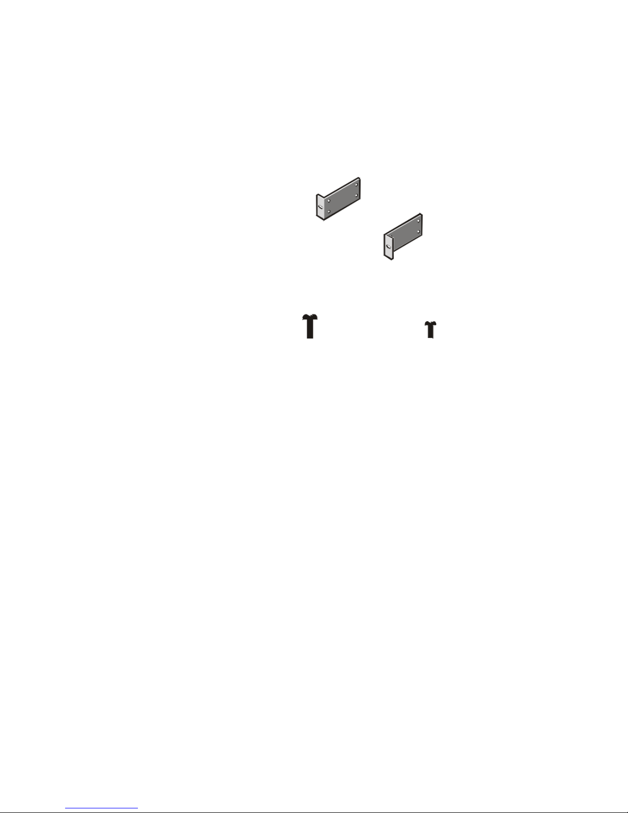
Rack Kit Contents
The rack kit includes the following items (see Figure 1-1):
• Two center-mount brackets
• Four 10-24 x 0.375-inch pan-head Phillips (or slotted) screws
• Two 12-24 x 0.5-inch pan-head Phillips screws
center-mount brackets (2)
12-24 x 0.5-inch pan-head
Phillips screws (2)
10-24 x 0.375-inch pan-head
Phillips screws (4)
Figure 1-1. Two-Post Center-Mount Rack Kit Contents
Recommended Tools and Supplies
You need the following tools and supplies to install the appliance in a two-post
open-frame relay rack:
• #2 Phillips screwdriver
• Masking tape or a felt-tip pen, for use in marking the mounting holes to be used
1-2 Rack Installation Guide

Marking the Rack
1. Determine where you want to place the bottom of the PowerApp appliance.
CAUTION: If you are installing more than one PowerApp appliance, install
the first appliance in the lowest available position in the rack.
2. Mark the upper and lower-mounting positions on the two posts.
Each 1-U (1.75-inch) vertical space has three holes, with center-to-center spacing
between holes (beginning at the center of the top hole of a 1-U space) of 0.625,
0.625, and 0.5 inch (see Figure 1-2).
0.5 inch
0.625 inch
1.75 inches (1 U)
0.625 inch
0.5 inch
Figure 1-2. Two-Post Open-Frame Relay Rack 1-U Hole Spacing
support.dell.com Rack Installation Guide 1-3
 Loading...