

Page 1

Dell Latitude 5480
Owner's Manual
Regulatory Model: P72G
Regulatory Type: P72G001
Page 2

Notes, cautions, and warnings
NOTE: A NOTE indicates important information that helps you make better use of your product.
CAUTION: A CAUTION indicates either potential damage to hardware or loss of data and tells you how to avoid the problem.
WARNING: A WARNING indicates a potential for property damage, personal injury, or death.
© 2017 Dell Inc. or its subsidiaries. All rights reserved. Dell, EMC, and other trademarks are trademarks of Dell Inc. or its subsidiaries. Other trademarks
may be trademarks of their respective owners.
2017 - 01
Rev. A00
Page 3

Contents
1 Working on your computer............................................................................................................................. 8
Safety instructions.............................................................................................................................................................8
Before working inside your computer..............................................................................................................................8
After working inside your computer.................................................................................................................................9
Turning o your computer................................................................................................................................................ 9
Turning o your computer — Windows 10...............................................................................................................9
Turning o your computer — Windows 7................................................................................................................ 9
2 Chassis view.................................................................................................................................................10
System front view............................................................................................................................................................ 10
System back view..............................................................................................................................................................11
System side view...............................................................................................................................................................11
System side view.............................................................................................................................................................. 12
System top view............................................................................................................................................................... 13
3 Removing and installing components............................................................................................................14
Recommended tools.........................................................................................................................................................14
Subscriber Identity Module(SIM) board........................................................................................................................ 14
Installing the Subscriber Identication Module (SIM) card................................................................................... 14
Removing the Subscriber Identication Module (SIM) card.................................................................................14
Base cover.........................................................................................................................................................................15
Removing base cover.................................................................................................................................................15
Installing base cover...................................................................................................................................................15
Battery............................................................................................................................................................................... 16
Removing battery....................................................................................................................................................... 16
Installing battery..........................................................................................................................................................16
Solid State Drive (SSD)....................................................................................................................................................17
Removing optional M.2 Solid State Drive (SSD).....................................................................................................17
Installing optional M.2 SSD........................................................................................................................................18
Hard drive.......................................................................................................................................................................... 18
Removing hard drive assembly................................................................................................................................. 18
Installing hard drive assembly....................................................................................................................................19
Coin cell battery................................................................................................................................................................19
Removing the coin cell battery................................................................................................................................. 19
Installing coin cell battery..........................................................................................................................................20
WLAN card....................................................................................................................................................................... 20
Removing WLAN card...............................................................................................................................................20
Installing WLAN card..................................................................................................................................................21
Memory module................................................................................................................................................................ 21
Removing memory module........................................................................................................................................21
Installing memory module..........................................................................................................................................22
Keyboard........................................................................................................................................................................... 22
Removing keyboard trim........................................................................................................................................... 22
Contents
3
Page 4

Installing keyboard trim..............................................................................................................................................23
Removing keyboard................................................................................................................................................... 23
Installing keyboard......................................................................................................................................................24
Heat sink........................................................................................................................................................................... 24
Removing heatsink ....................................................................................................................................................24
Installing heat sink .....................................................................................................................................................25
System fan........................................................................................................................................................................25
Removing the system fan......................................................................................................................................... 25
Installing the system fan............................................................................................................................................26
Power connector port..................................................................................................................................................... 26
Removing power connector port............................................................................................................................. 26
Installing power connector port................................................................................................................................27
Chassis frame................................................................................................................................................................... 27
Removing chassis frame............................................................................................................................................27
Installing chassis frame..............................................................................................................................................29
System board....................................................................................................................................................................29
Removing system board............................................................................................................................................29
Installing system board.............................................................................................................................................. 32
Touchpad buttons board................................................................................................................................................. 33
Removing touchpad panel........................................................................................................................................ 33
Installing touchpad panel...........................................................................................................................................33
SmartCard module...........................................................................................................................................................34
Removing smart card reader board......................................................................................................................... 34
Installing smart card reader board............................................................................................................................35
LED board......................................................................................................................................................................... 35
Removing LED board.................................................................................................................................................35
Installing LED board...................................................................................................................................................36
Speaker............................................................................................................................................................................. 36
Removing speaker..................................................................................................................................................... 36
Installing speaker........................................................................................................................................................ 37
Display assembly.............................................................................................................................................................. 38
Removing display assembly...................................................................................................................................... 38
Installing display assembly..........................................................................................................................................41
Display bezel..................................................................................................................................................................... 42
Removing display bezel............................................................................................................................................. 42
Installing display bezel................................................................................................................................................42
Display hinge cover..........................................................................................................................................................43
Removing display hinge cover..................................................................................................................................43
Installing display hinge cover.................................................................................................................................... 43
Display hinges................................................................................................................................................................... 44
Removing display hinge.............................................................................................................................................44
Installing display hinge............................................................................................................................................... 45
Display panel.....................................................................................................................................................................45
Removing display panel.............................................................................................................................................45
Installing display panel................................................................................................................................................47
eDP cable..........................................................................................................................................................................48
Removing eDP cable................................................................................................................................................. 48
Contents
4
Page 5

Installing eDP cable....................................................................................................................................................48
Camera..............................................................................................................................................................................49
Removing camera...................................................................................................................................................... 49
Installing camera........................................................................................................................................................ 50
Palm rest...........................................................................................................................................................................50
Removing palm rest...................................................................................................................................................50
Installing palmrest....................................................................................................................................................... 51
4 Technology and components........................................................................................................................52
Power adapter.................................................................................................................................................................. 52
Processors........................................................................................................................................................................ 52
Skylake processor...................................................................................................................................................... 52
Kaby Lake — 7th Generation Intel Core processors............................................................................................. 53
Identifying processors in Windows 10..................................................................................................................... 54
Verifying the processor usage in Task Manager.................................................................................................... 54
Verifying the processor usage in Resource Monitor..............................................................................................54
Chipsets............................................................................................................................................................................ 55
Intel chipset drivers................................................................................................................................................... 55
Downloading the chipset driver............................................................................................................................... 56
Identifying the chipset in Device Manager on Windows 10..................................................................................56
Graphic options................................................................................................................................................................56
Intel HD Graphics drivers.......................................................................................................................................... 57
Downloading drivers.................................................................................................................................................. 57
Display options..................................................................................................................................................................57
Identifying the display adapter..................................................................................................................................57
Changing the screen resolution............................................................................................................................... 58
Rotating the display...................................................................................................................................................58
Adjusting brightness in Windows 10........................................................................................................................ 58
Cleaning the display...................................................................................................................................................59
Using touch screen in Windows 10..........................................................................................................................59
Connecting to external display devices...................................................................................................................59
Realtek ALC3246 Waves MaxxAudio Pro controller....................................................................................................59
Downloading the audio driver...................................................................................................................................60
Identifying the audio controller in Windows 10.......................................................................................................60
Changing the audio settings.....................................................................................................................................60
WLAN cards..................................................................................................................................................................... 60
Secure Boot screen options...................................................................................................................................... 61
Hard drive options............................................................................................................................................................ 61
Identifying the hard drive in Windows 10.................................................................................................................61
Identifying the hard drive in the BIOS......................................................................................................................61
Camera features...............................................................................................................................................................62
Identifying the camera in Device Manager on Windows 10..................................................................................62
Starting the camera...................................................................................................................................................62
Starting the camera application...............................................................................................................................62
Memory features..............................................................................................................................................................63
Verifying system memory in Windows 10................................................................................................................63
Verifying system memory in system setup (BIOS)................................................................................................64
Contents
5
Page 6

Testing memory using ePSA.....................................................................................................................................64
Realtek HD audio drivers.................................................................................................................................................64
Thunderbolt over Type-C................................................................................................................................................64
Thunderbolt 3 over Type-C...................................................................................................................................... 65
Key Features of Thunderbolt 3 over USB Type-C ................................................................................................65
Thunderbolt Icons......................................................................................................................................................66
5 System setup options.................................................................................................................................. 67
Boot Sequence.................................................................................................................................................................67
Navigation keys................................................................................................................................................................68
System Setup overview.................................................................................................................................................. 68
Accessing System Setup................................................................................................................................................ 68
General screen options....................................................................................................................................................68
System Conguration screen options........................................................................................................................... 69
Video screen options........................................................................................................................................................71
Security screen options....................................................................................................................................................71
Secure Boot screen options............................................................................................................................................73
Intel Software Guard Extensions....................................................................................................................................73
Performance screen options...........................................................................................................................................74
Power Management screen options.............................................................................................................................. 74
POST Behavior screen options...................................................................................................................................... 76
Virtualization support screen options............................................................................................................................ 77
Wireless screen options................................................................................................................................................... 77
Maintenance screen options...........................................................................................................................................78
System Log screen options.............................................................................................................................................78
Updating the BIOS in Windows .....................................................................................................................................78
System and setup password...........................................................................................................................................79
Assigning a system password and setup password...............................................................................................79
Deleting or changing an existing system and/or setup password....................................................................... 80
6 Technical specications................................................................................................................................81
System specications.......................................................................................................................................................81
Processor specications................................................................................................................................................. 82
Memory specications.................................................................................................................................................... 82
Storage specications.....................................................................................................................................................82
Audio specications......................................................................................................................................................... 82
Video specications.........................................................................................................................................................83
Camera specications..................................................................................................................................................... 83
Communication specications........................................................................................................................................83
Port and connector specications.................................................................................................................................84
Contactless smart card specications.......................................................................................................................... 84
Display specications.......................................................................................................................................................84
Keyboard specications.................................................................................................................................................. 85
Touchpad specications..................................................................................................................................................85
Battery specications......................................................................................................................................................86
AC Adapter specications...............................................................................................................................................86
Physical specications.....................................................................................................................................................87
Contents
6
Page 7

Environmental specications.......................................................................................................................................... 87
7 Diagnostics.................................................................................................................................................. 88
Enhanced Pre-Boot System Assessment (ePSA) diagnostics...................................................................................88
Device status lights..........................................................................................................................................................89
Battery status lights........................................................................................................................................................ 90
8 Troubleshooting............................................................................................................................................91
Enhanced Pre-Boot System Assessment (ePSA) diagnostics....................................................................................91
Running the ePSA diagnostics..................................................................................................................................91
Real Time Clock (RTC) reset.......................................................................................................................................... 91
9 Contacting Dell............................................................................................................................................93
Contents 7
Page 8

Working on your computer
Safety instructions
Use the following safety guidelines to protect your computer from potential damage and to ensure your personal safety. Unless otherwise
noted, each procedure included in this document assumes that the following conditions exist:
• You have read the safety information that shipped with your computer.
• A component can be replaced or, if purchased separately, installed by performing the removal procedure in reverse order.
WARNING: Disconnect all power sources before opening the computer cover or panels. After you nish working inside the
computer, replace all covers, panels, and screws before connecting to the power source.
WARNING: Before working inside your computer, read the safety information that shipped with your computer. For additional
safety best practices information, see the Regulatory Compliance Homepage at www.dell.com/regulatory_compliance
CAUTION: Many repairs may only be done by a certied service technician. You should only perform troubleshooting and simple
repairs as authorized in your product documentation, or as directed by the online or telephone service and support team. Damage
due to servicing that is not authorized by Dell is not covered by your warranty. Read and follow the safety instructions that came
with the product.
1
CAUTION: To avoid electrostatic discharge, ground yourself by using a wrist grounding strap or by periodically touching an
unpainted metal surface at the same time as touching a connector on the back of the computer.
CAUTION: Handle components and cards with care. Do not touch the components or contacts on a card. Hold a card by its
edges or by its metal mounting bracket. Hold a component such as a processor by its edges, not by its pins.
CAUTION: When you disconnect a cable, pull on its connector or on its pull-tab, not on the cable itself. Some cables have
connectors with locking tabs; if you are disconnecting this type of cable, press in on the locking tabs before you disconnect the
cable. As you pull connectors apart, keep them evenly aligned to avoid bending any connector pins. Also, before you connect a
cable, ensure that both connectors are correctly oriented and aligned.
NOTE: The color of your computer and certain components may appear dierently than shown in this document.
Before working inside your computer
1 Ensure that your work surface is at and clean to prevent the computer cover from being scratched.
2 Turn o your computer.
3 If the computer is connected to a docking device (docked), undock it.
4 Disconnect all network cables from the computer (if available).
CAUTION
computer.
5 Disconnect your computer and all attached devices from their electrical outlets.
6 Open the display.
7 Press and hold the power button for few seconds, to ground the system board.
: If your computer has an RJ45 port, disconnect the network cable by rst unplugging the cable from your
CAUTION
8.
CAUTION: To avoid electrostatic discharge, ground yourself by using a wrist grounding strap or by periodically touching
an unpainted metal surface at the same time as touching a connector on the back of the computer.
8 Working on your computer
: To guard against electrical shock unplug your computer from the electrical outlet before performing Step #
Page 9

8 Remove any installed ExpressCards or Smart Cards from the appropriate slots.
After working inside your computer
After you complete any replacement procedure, ensure you connect any external devices, cards, and cables before turning on your
computer.
CAUTION: To avoid damage to the computer, use only the battery designed for this particular Dell computer. Do not use batteries
designed for other Dell computers.
1 Replace the battery.
2 Replace the base cover.
3 Connect any external devices, such as a port replicator or media base, and replace any cards, such as an ExpressCard.
4 Connect any telephone or network cables to your computer.
CAUTION: To connect a network cable, rst plug the cable into the network device and then plug it into the
computer.
5 Connect your computer and all attached devices to their electrical outlets.
6 Turn on your computer.
Turning o your computer
Turning o your computer — Windows 10
CAUTION
computer.
1 Click or tap .
2 Click or tap and then click or tap Shut down.
: To avoid losing data, save and close all open les and exit all open programs before you turn o your
NOTE
: Ensure that the computer and all attached devices are turned o. If your computer and attached devices did not
automatically turn o when you shut down your operating system, press and hold the power button for about 6 seconds
to turn them o.
Turning o your computer — Windows 7
CAUTION
computer.
1 Click Start.
2 Click Shut Down.
: To avoid losing data, save and close all open les and exit all open programs before you turn o your
: Ensure that the computer and all attached devices are turned o. If your computer and attached devices did not
NOTE
automatically turn o when you shut down your operating system, press and hold the power button for about 6 seconds
to turn them o.
Working on your computer 9
Page 10
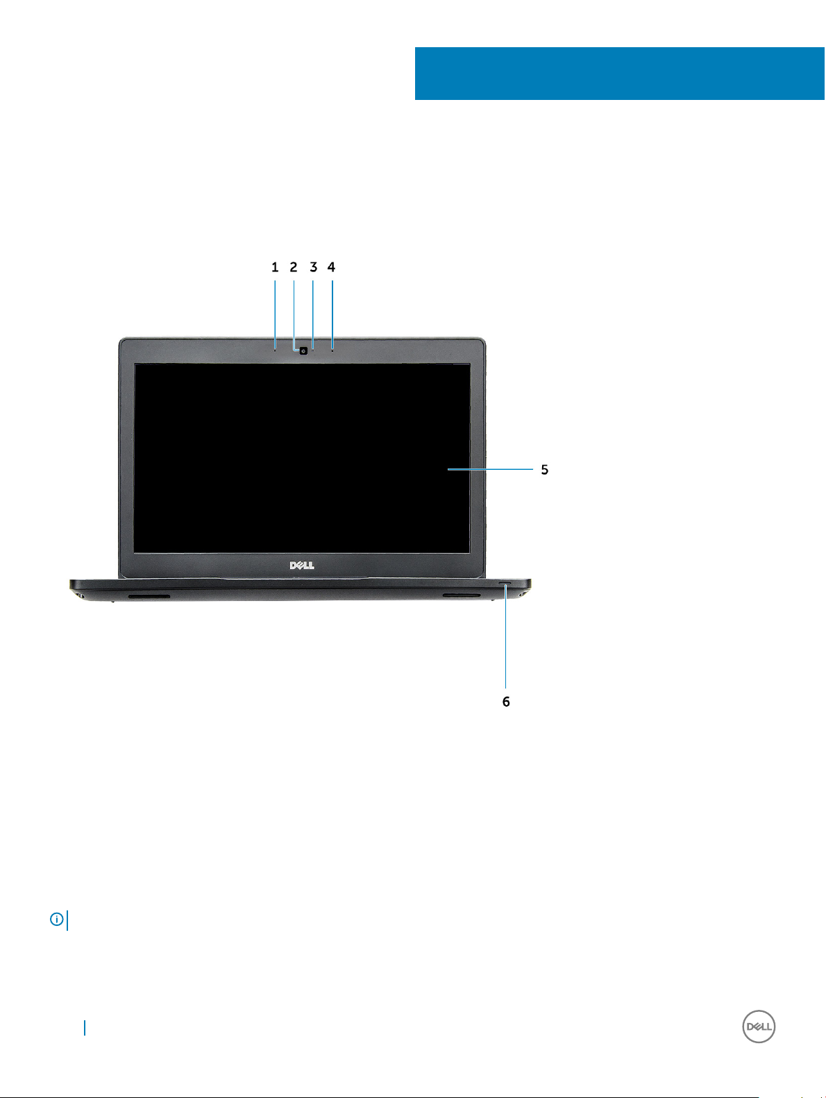
System front view
2
Chassis view
Figure 1. Front view
1 Dual array microphone
2 Camera
3 Camera status light
4 Dual array microphone
5 Display
6 Dattery and charge status light
: Latitude 5480 computer also has an optional IR camera module.
NOTE
10 Chassis view
Page 11
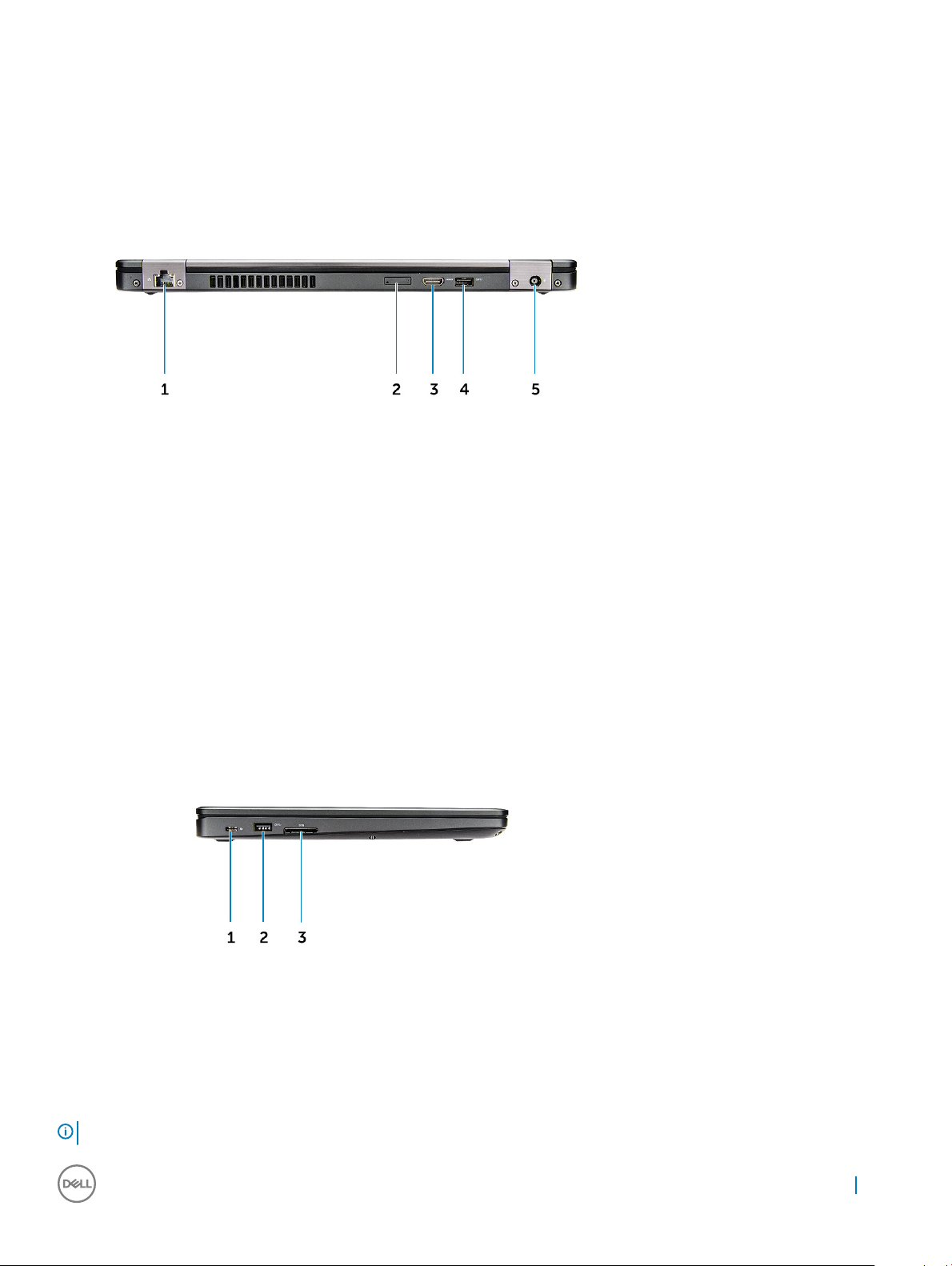
System back view
Figure 2. Back view
1 Network port
2 uSim card slot (optional)
3 HDMI port
4 USB 3.0 port
5 Power connector port
System side view
Figure 3. Left view
1 Type-C connector/DisplayPort or USB 3.0/optional Thunderbolt3
2 USB 3.0 port
3 SD card reader
: Latitude 5480 computer also has an optional Smart card reader.
NOTE
Chassis view 11
Page 12

System side view
Figure 4. Right view
1 Headset/microphone port
2 USB 3.0 port with PowerShare
3 VGA port
4 Noble wedge lock slot
12
Chassis view
Page 13
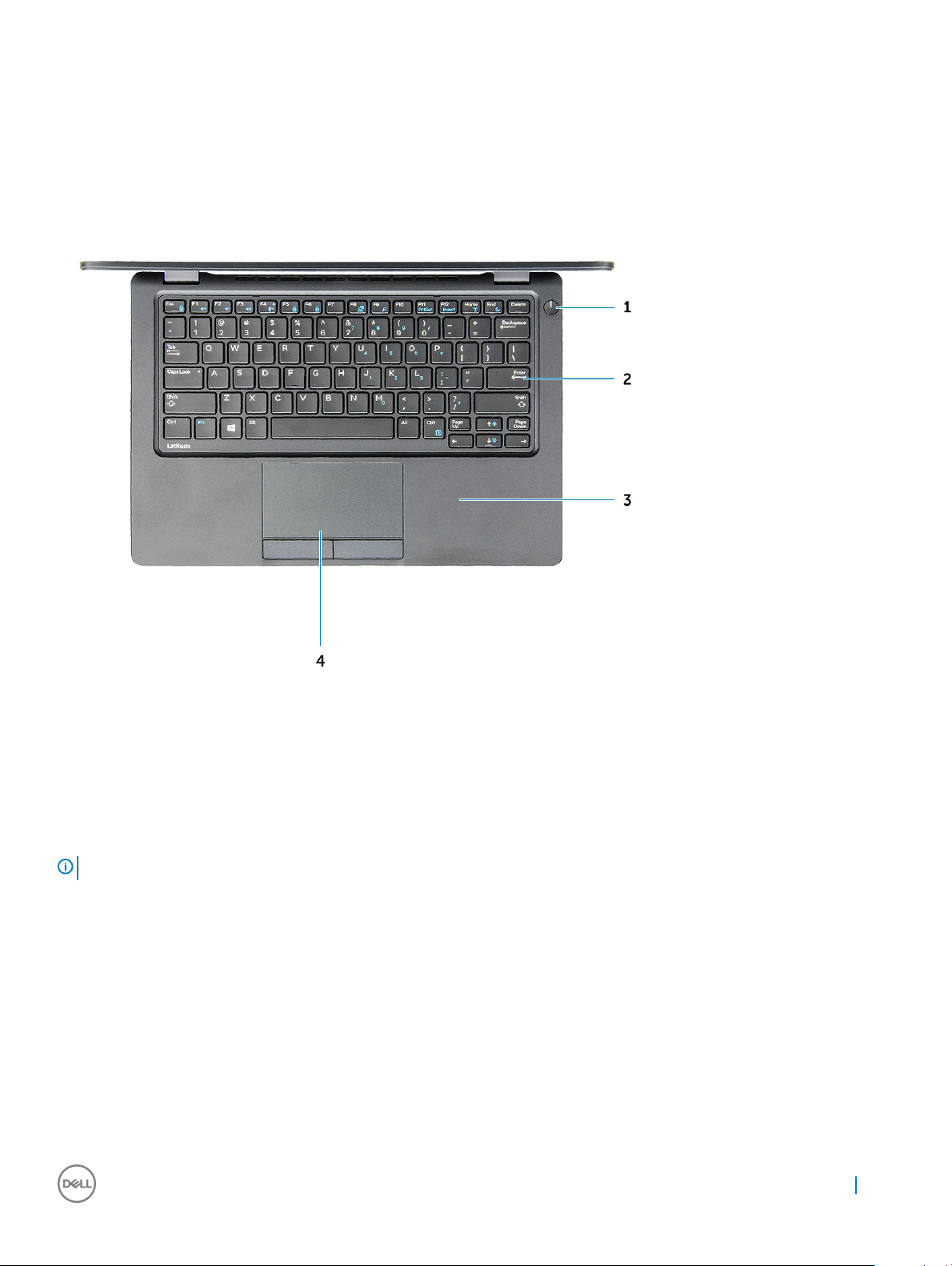
System top view
Figure 5. Top view
1 Power button
2 Keyboard
3 Palm rest
4 Touchpad
NOTE
: Latitude 5480 computer also has an optional ngerprint reader.
Chassis view 13
Page 14
Removing and installing components
This section provides detailed information on how to remove or install the components from your computer.
Recommended tools
The procedures in this document require the following tools:
• Phillips #0 screwdriver
• Phillips #1 screwdriver
• Small plastic scribe
Subscriber Identity Module(SIM) board
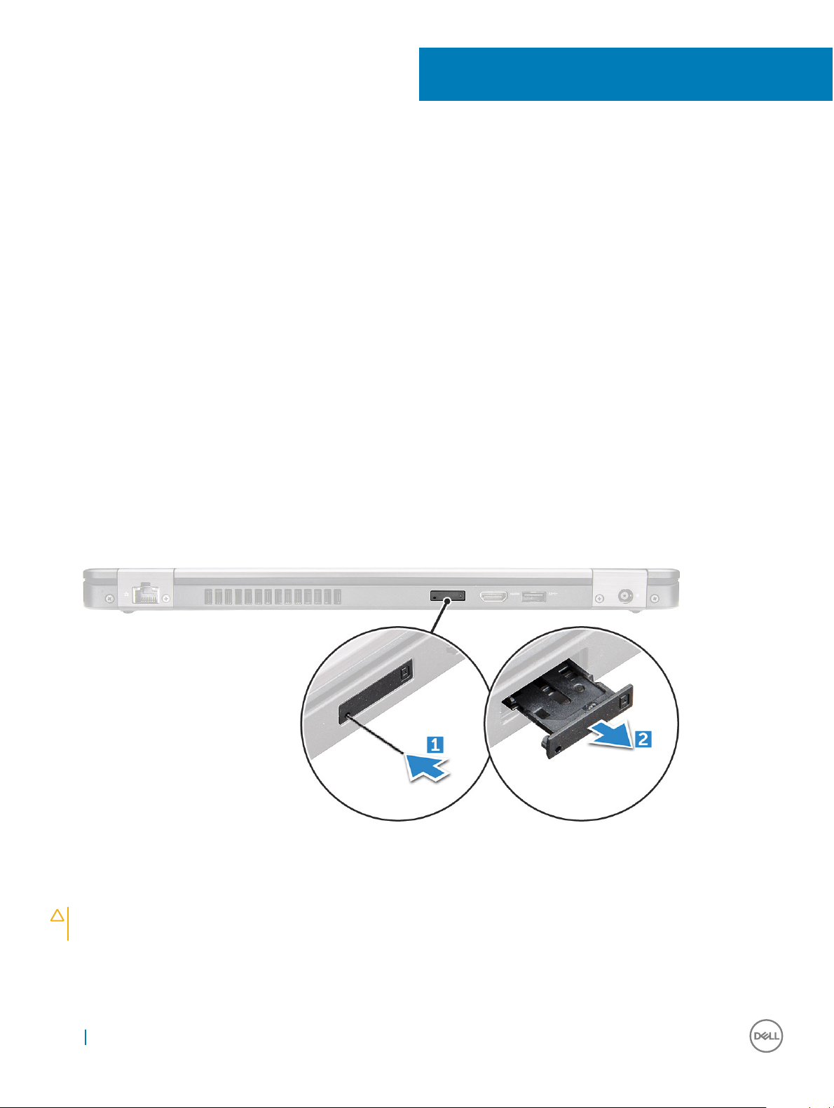
Installing the Subscriber Identication Module (SIM) card
1 Follow the procedure in After working inside your computer.
2 Insert a paperclip or a SIM card removal tool into the pinhole [1].
3 Pull the SIM card tray to remove it [2].
4 Place the SIM card on the SIM card tray.
5 Push the SIM card tray into the slot until it clicks into place.
3
Removing the Subscriber Identication Module (SIM) card
CAUTION
turned o or the network connections are disabled.
1 Insert a paperclip or a SIM card removal tool into the pinhole on the SIM card tray.
2 Pull the SIM card tray to remove it.
3 Remove the SIM card from the SIM card tray.
14 Removing and installing components
: Removing the SIM card when the computer is on may cause data loss or damage the card. Ensure your computer is
Page 15
4 Push the SIM card tray into the slot until it clicks into place.
Base cover
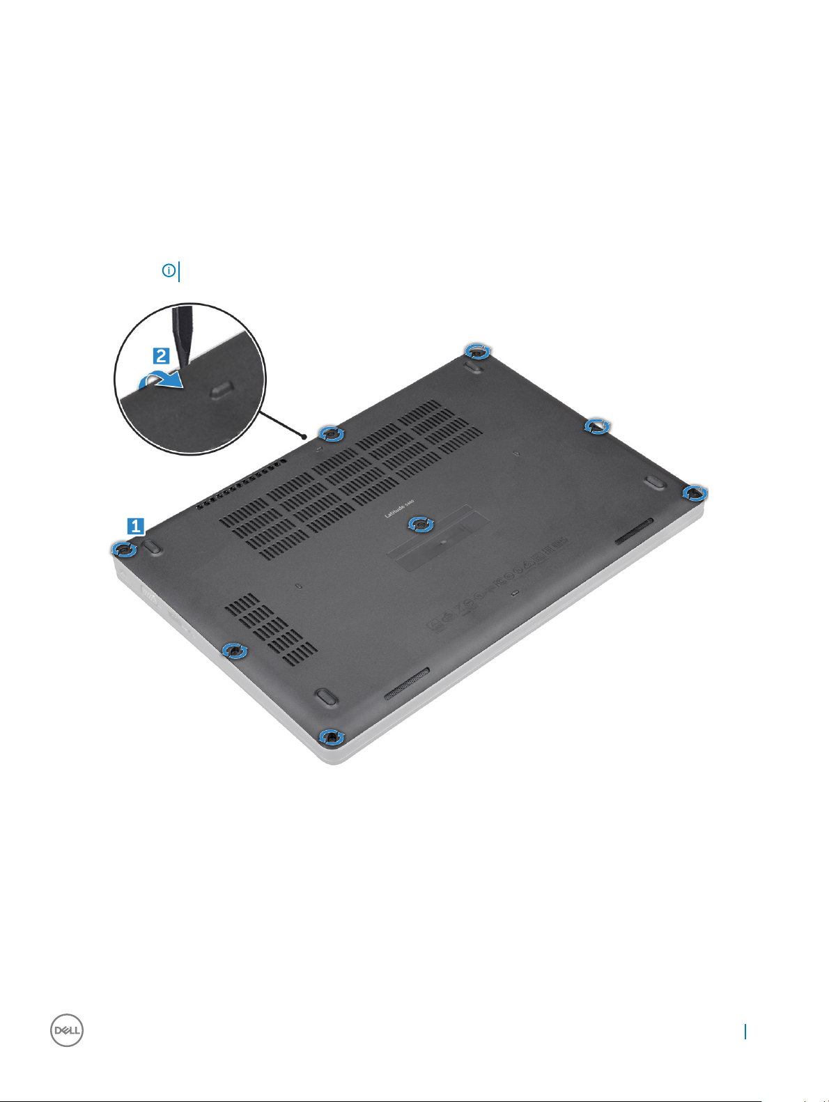
Removing base cover
1 Follow the procedure in Before working inside your computer.
2 To remove the base cover:
a Loosen the M2.5*6.3 captive screws that secure the base cover to the computer [1].
b Pry the base cover from the edge and lift the base cover away from the computer [2].
NOTE: You may need a plastic scribe to pry the base cover from the edges.
Installing base cover
1 Place the base cover to align with the screw holders on the computer.
2 Tighten the M2.5 captive screws to secure the base cover to the computer.
3 Follow the procedure in After working inside your computer.
Removing and installing components
15
Page 16

Battery
Removing battery
1 Follow the procedure in Before working inside your computer.
2 Remove the base cover.
3 To remove the battery:
a Disconnect the battery cable from the connector on the system board [1].
b Unroute the battery cable from the routing channels.
c Remove the M2*6 captive screw that secures the battery to the computer [2].
NOTE: 6-cell battery has 2 screws.
d Lift the battery from the computer [3].
Installing battery
1 Insert the battery into the slot on the computer.
2 Route the battery cable through the routing channels.
3 Tighten the M2*6 captive screw to secure the battery to the computer.
4 Connect the battery cable to the connector on the system board.
5 Install the base cover.
6 Follow the procedure in After working inside your computer.
16
Removing and installing components
Page 17
Solid State Drive (SSD)
Removing optional M.2 Solid State Drive (SSD)
1 Follow the procedure in Before working inside your computer.
2 Remove the:
a base cover
b battery
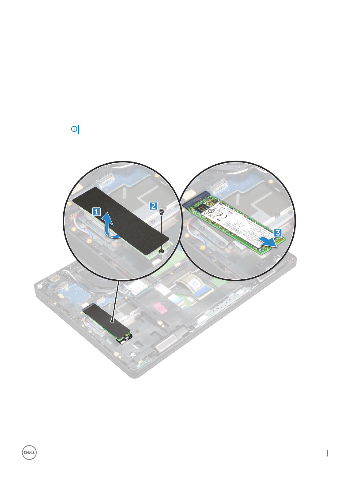
3 To remove the SSD card:
a Remove the SSD bracket from the SSD card.
NOTE: The SSD bracket is shipped along with the SSD card kit.
b Peel the adhesive tape that secures the SSD card [1].
c Remove the M2*3 screw that secures the SSD to the computer [2].
d Slide and lift the SSD from the computer [3].
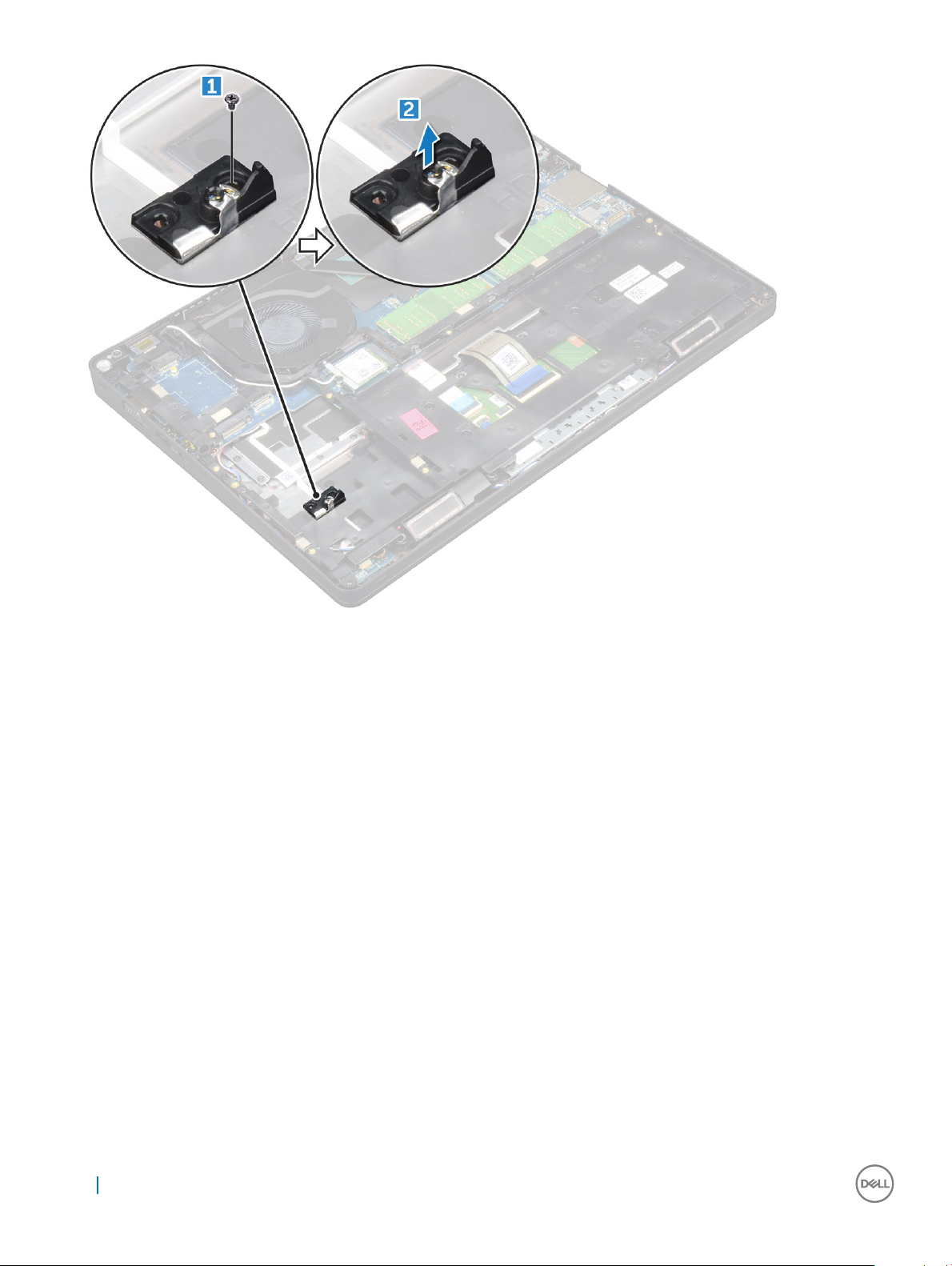
4 To remove the SSD clip:
a Remove the M2*3 screw that secures the SSD clip to the computer [1].
b Lift the SSD clip away from the computer [2].
Removing and installing components
17
Page 18
Installing optional M.2 SSD
1 Insert the SSD clip into the slot on the computer.
2 Tighten the M2*3 screw to secure the SSD clip to the computer.
3 Insert the SSD into the connector on the computer.
4 Place the SSD bracket over the SSD and tighten the M2*3 screw to secure it to the computer.
5 Install the:
a battery
b base cover
6 Follow the procedure in After working inside your computer.
Hard drive
Removing hard drive assembly
1 Follow the procedure in Before working inside your computer.
2 Remove the:
a base cover
b battery
3 To remove the hard drive assembly:
a Disconnect the hard drive cable from the connector on the system board.
b Remove the screws that secure the hard drive assembly to the computer.
18
Removing and installing components
Page 19
c Lift the hard drive assembly away from the compute.
Installing hard drive assembly
1 Insert the hard drive assembly into the slot on the computer.
2 Tighten the screws to secure the hard drive assembly to the computer.
3 Connect the hard drive cable to the connector on the hard drive and on the system board.
4 Install the:
a battery
b base cover
5 Follow the procedures in After working inside your system.
Coin cell battery
Removing the coin cell battery
1 Follow the procedure in Before working inside your computer.
2 Remove the:
a base cover
b battery
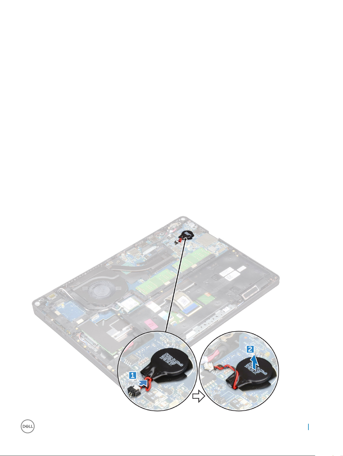
3 To remove the coin cell battery:
a Disconnect the coin cell battery cable from the connector on the system board [1].
b Lift the coin cell battery to release from the adhesive and lift it away from the system board [2].
Removing and installing components
19
Page 20
Installing coin cell battery
1 Ax the coin cell battery on the system board.
2 Connect the coin cell battery cable to the connector on the system board.
3 Install the:
a battery
b base cover
4 Follow the procedure in After working inside your computer.
WLAN card
Removing WLAN card
1 Follow the procedure in Before working inside your computer.
2 Remove the:
a base cover
b battery
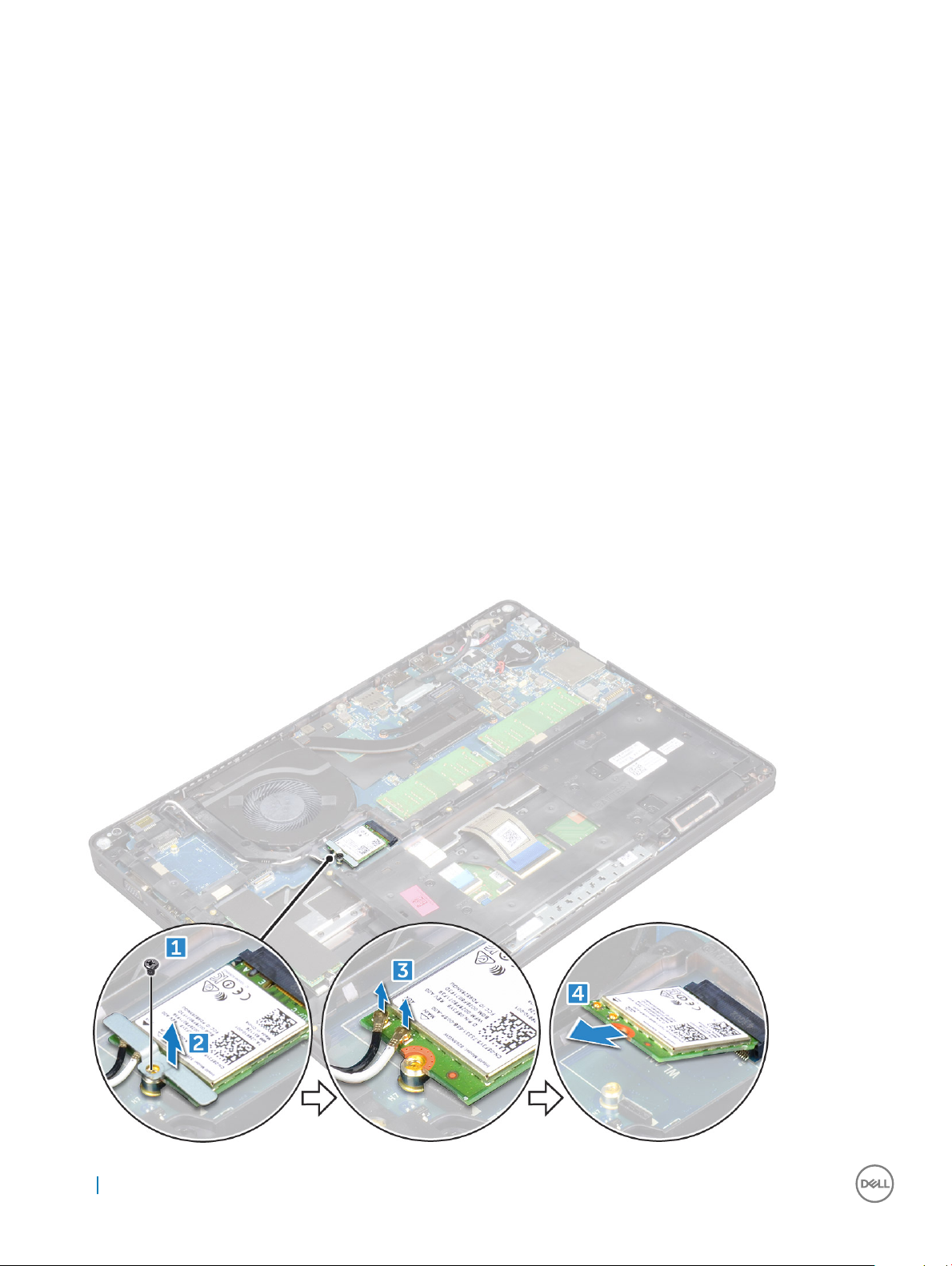
3 To remove the WLAN card:
a Remove the M2*3 screw that secures the WLAN card to the computer [1].
b Remove the metal bracket that secures the WLAN cables [2].
c Disconnect the WLAN cables from the connectors on the WLAN card [3].
d Lift the WLAN card away from the connector [4].
20
Removing and installing components
Page 21
Installing WLAN card
1 Insert the WLAN card into the connector on the system board.
2 Place the metal bracket to secure the WLAN cables.
3 Tighten the M2*3 screw to secure the WLAN card to the computer.
4 Connect the WLAN cables to the connectors on the WLAN card.
5 Install the:
a battery
b base cover
6 Follow the procedure in After working inside your computer.
Memory module
Removing memory module
1 Follow the procedure in Before working inside your computer.
2 Remove the:
a base cover
b battery
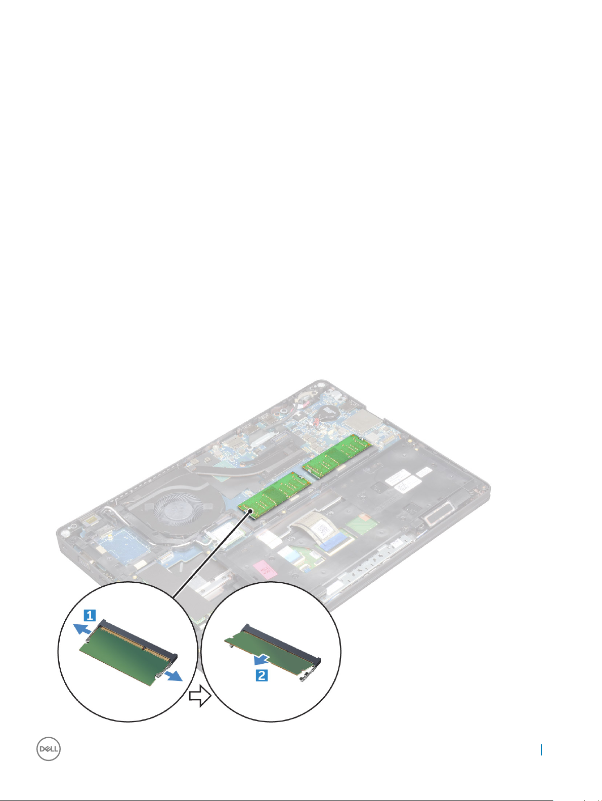
3 To remove the memory module:
a Pry the clips securing the memory module until the memory module pops-up [1].
b Lift the memory module away from the connector [2].
Removing and installing components
21
Page 22
Installing memory module
1 Insert the memory module on the memory connector until the clips secure the memory module.
2 Install the:
a battery
b base cover
3 Follow the procedure in After working inside your computer.
Keyboard
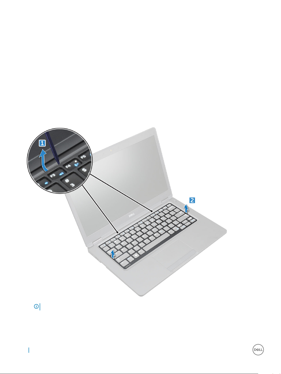
Removing keyboard trim
1 Follow the procedure in Before working inside your computer.
2 Pry the keyboard trim from the edges [1] and lift it away from the computer [2].
NOTE: You may need a plastic scribe to pry the keyboard trim from the edges.
22 Removing and installing components
Page 23
Installing keyboard trim
1 Place the keyboard trim on the keyboard and press on the edges until it clicks in place.
2 Follow the procedure in After working inside your computer.
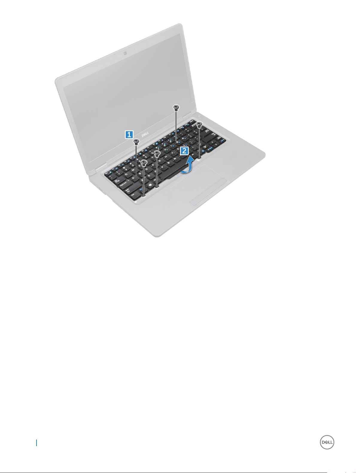
Removing keyboard
1 Follow the procedure in Before working inside your computer.
2 Remove the:
a base cover
b battery
c keyboard trim
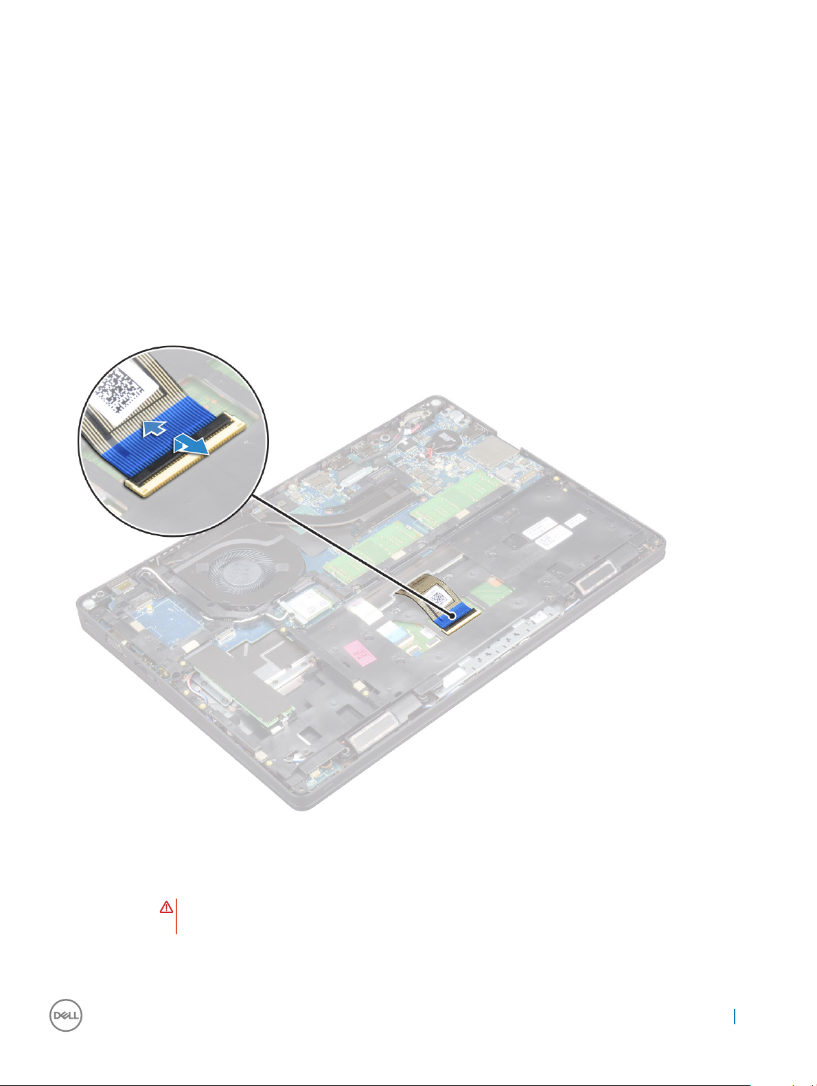
3 Lift the latch and disconnect the keyboard cable from the connector.
4 Turn over the computer and open the display.
5 To remove the keyboard:
a Remove the M2*2 screws that secure the keyboard to the computer [1].
b Pry the keyboard from the edge and lift it away from the computer [2].
WARNING
keyboard cable.
: Make sure you pull the keyboard cable routed under the computer to avoid any damage to the
Removing and installing components 23
Page 24
Installing keyboard
1 Hold the keyboard and route the keyboard cable through the placeholder.
2 Place the keyboard to align with the screw holders on the computer.
3 Tighten the M2*2 screws to secure the keyboard to the computer.
4 Connect the keyboard cable to the connector.
5 Install the:
a keyboard trim
b battery
c base cover
6 Follow the procedure in After working inside your computer.
Heat sink
Removing heatsink
1 Follow the procedure in Before working inside your computer.
2 Remove the:
a base cover
b battery
24
Removing and installing components
Page 25
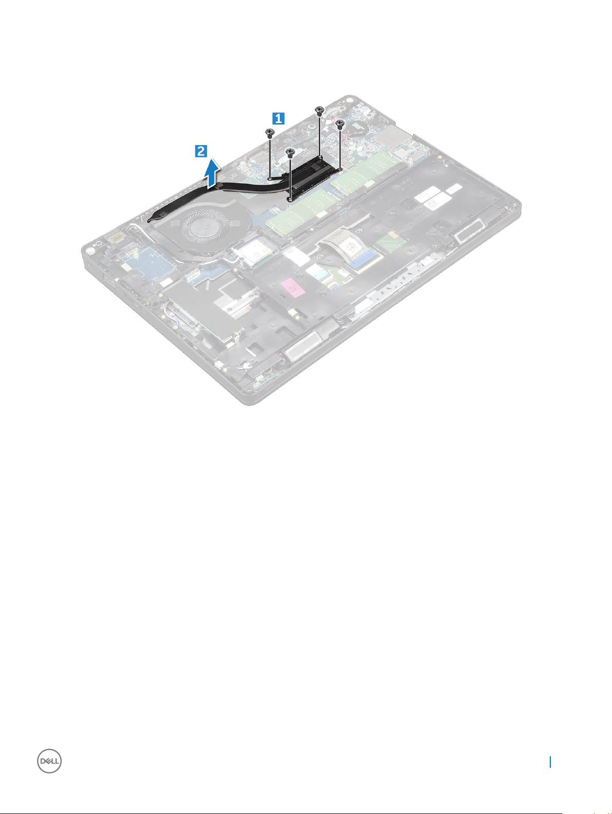
3 To remove the heat sink :
a Disconnect the system fan cable from the connector on the system board [1]
b Remove the M2*3 screws that secure the heat sink on the system board [2].
c Lift the heat sink away from the system board.
Installing heat sink
1 Place the heat sink on the system board.
2 Tighten the M2*3 screws to secure the heat sink to the computer.
3 Connect the system fan cable to the connector on the system board.
4 Install the:
a battery
b base cover
5 Follow the procedure in After working inside your computer.
System fan
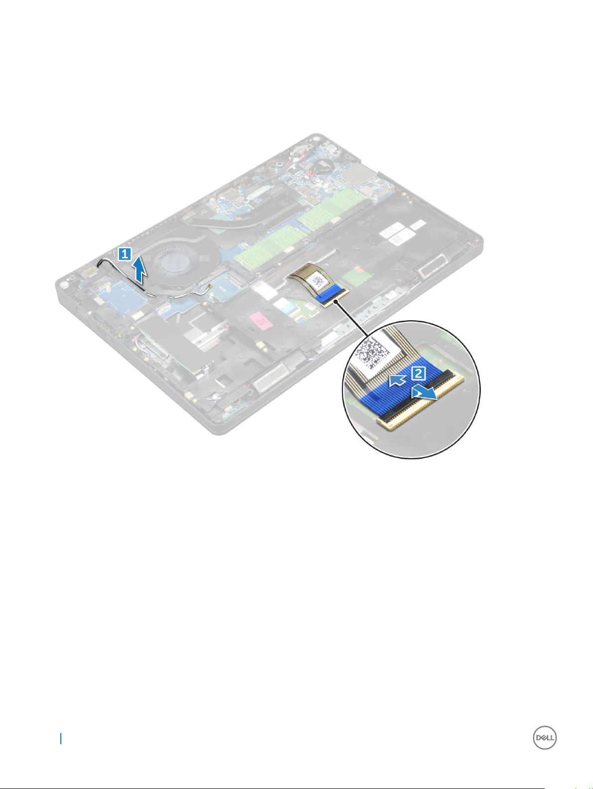
Removing the system fan
1 Follow the procedure in Before working inside your computer.
2 Remove the:
a base cover
b battery
c chassis frame
3 To remove the system fan:
Removing and installing components
25
Page 26
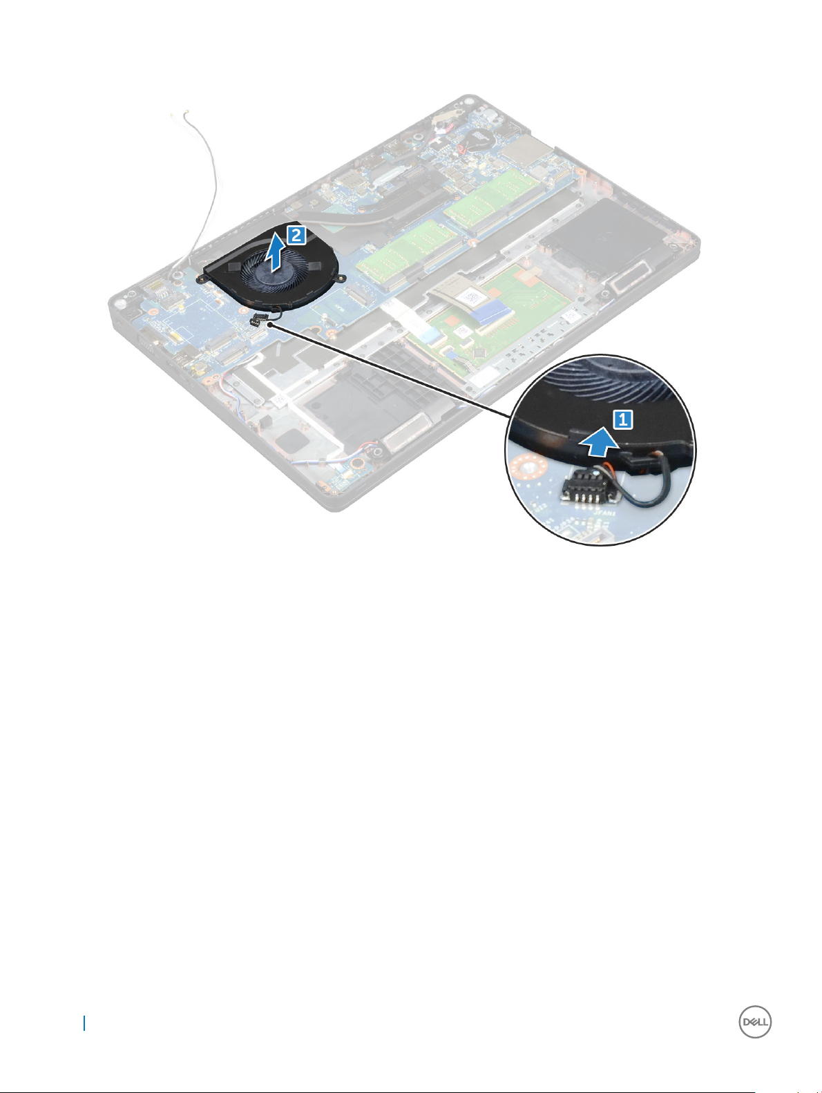
a Disconnect the system fan cable from the connector on the system board [1].
b Lift the system fan away from the computer [2].
Installing the system fan
1 Place the system fan into the slot on the computer.
2 Connect the system fan cable to the connector on the system board.
3 Install the:
a chassis frame
b battery
c base cover
4 Follow the procedure in After working inside your computer.
Power connector port
Removing power connector port
1 Follow the procedure in Before working inside your computer.
2 Remove the:
a base cover
b battery
3 To remove the power connector port:
a Remove the M2*3 screw that secures the display cable to the computer [1].
26
Removing and installing components
Page 27
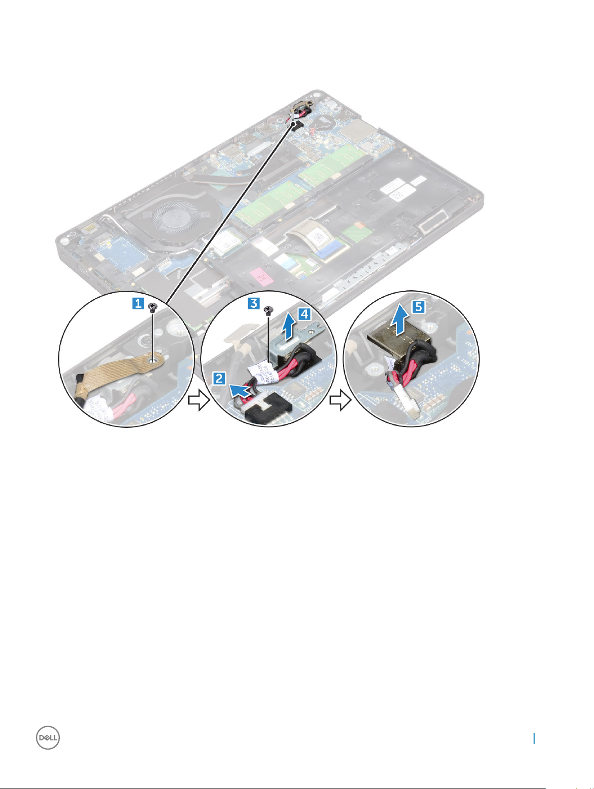
b Disconnect the power connector port cable from the connector on the system board [2].
c Remove the M2*3 screw to release the metal bracket that secures the power connector port [3].
d Lift the metal bracket [4].
e Lift the power connector port away from the computer [5].
Installing power connector port
1 Align the power connector port along the grooves on the slot and push it down.
2 Place the metal bracket on the power connector port.
3 Tighten the M2*3 screw to secure the power connector port to the computer
4 Connect the power connector port cable to the connector on the system board.
5 Tighten the M2*3 screw to secure the display cable to the computer.
6 Install the:
a battery
b base cover
7 Follow the procedure in After working inside your computer.
Chassis frame
Removing chassis frame
1 Follow the procedure in Before working inside your computer.
2 Remove the:
Removing and installing components
27
Page 28
a base cover
b battery
c WLAN card
d SSD card
3 To release the chassis frame:
a Release the WLAN cables from the routing channels [1].
b Lift the latch and disconnect the keyboard cable from the connector [2].
To remove the chassis frame:
4
a Remove the M2*2, M2*3, and M2*5 screws that secure the chassis frame to the computer [1].
b Lift the chassis frame away from the computer [2].
28
Removing and installing components
Page 29

Installing chassis frame
1 Place the chassis frame on the computer.
2 Tighten the M2*2, M2*3, and M2*5 screws to secure the chassis frame to the computer.
3 Connect the keyboard cable to the connector.
4 Connect the speaker cable to the connector on the system board.
5 Route the WLAN cables through the routing channels.
6 Install the:
a SSD card
b WLAN card
c battery
d base cover
7 Follow the procedure in After working inside your system.
System board
Removing system board
1 Follow the procedure in Before working inside your computer.
2 Remove the:
a SIM card
b base cover
c battery
d keyboard trim
Removing and installing components
29
Page 30

e keyboard
f WLAN card
g SSD card
h memory module
i coin cell battery
j heatsink
k system fan
l chassis frame
3 Disconnect the following cables from the system board:
a LED board [1]
b speaker [2]
c touchpad [3]
4 To release the system board:
a Remove the M2*2 screw that secures the display cable [1].
b Lift the metal bracket that secures the display cable [2].
c Disconnect the display cable from the connectors on the system board [3].
d Disconnect the power connector port cable from the connector on the system board [4].
e Remove the M2*2 screws that secure the metal bracket[5] .
: The metal bracket secures the DisplayPort over USB Type-C.
NOTE
f Lift the metal bracket away from the system board [6].
30
Removing and installing components
Page 31

5 To remove the system board:
a Remove the M2*2 screws that secure the system board to the computer [1].
b Lift the system board away from the computer [2].
Removing and installing components
31
Page 32

Installing system board
1 Align the system board with the screw holders on the computer.
2 Tighten the M2*2 screws to secure the system board to the computer.
3 Place the metal bracket to secure the DisplayPort over USB Type-C.
4 Tighten the M2*2 screws to secure the metal bracket on the DisplayPort over USB Type-C.
5 Connect the power connector port cable to the connector on the system board.
6 Connect the display cables to the connectors on the system board.
7 Place the metal bracket to secure the display cable.
8 Tighten the M2*2 screw to secure the metal bracket.
9 Connect the following cables:
a touchpad
b speaker
c LED board
10 Install the:
a chassis frame
b system fan
c heat sink
d coin cell battery
e memory module
f SSD card
g WLAN card
h keyboard trim
i keyboard
32
Removing and installing components
Page 33

j battery
k base cover
l SIM card
11 Follow the procedure in After working inside your computer.
Touchpad buttons board
Removing touchpad panel
1 Follow the procedure in Before working inside your computer.
2 Remove the:
a base cover
b battery
c WLAN card
d SSD card
e chassis frame
3 To remove the touchpad panel:
a Lift the latch and disconnect the touchpad panel cable from the connector [1].
b Remove the screws that secure the touchpad panel to the computer [2].
c Lift the touchpad panel away from the computer.
Installing touchpad panel
1 Align the touchpad panel with the tabs on the computer.
2 Tighten the screws to secure the touchpad panel to the computer.
Removing and installing components
33
Page 34

3 Connect the touchpad panel cable to the connector.
4 Ax the adhesive tapes to secure the speaker cable to the touchpad panel.
5 Ax the smart card reader board cable.
6 Connect the smart card reader board to the connector.
7 Install the:
a chassis frame
b SSD card
c WLAN card
d battery
e base cover
8 Follow the procedure in After working inside your computer.
SmartCard module
Removing smart card reader board
1 Follow the procedure in Before working inside your computer.
2 Remove the:
a base cover
b battery
c WLAN card
d SSD card
e chassis frame
3 To remove the smart card reader board:
a Remove the screws that secure the smart card reader board to the palmrest [1].
b Slide and remove the smart card reader from the slot [2].
34
Removing and installing components
Page 35

Installing smart card reader board
1 Insert the smart card reader board to align with the tabs on the chassis..
2 Tighten the screws to secure the smart card reader board to the computer.
3 Ax the smart card reader board cable and connect the cable to the connector.
4 Install the:
a chassis frame
b SSD card
c WLAN card
d battery
e base cover
5 Follow the procedure in After working inside your computer.
LED board
Removing LED board
1 Follow the procedure in Before working inside your computer.
2 Remove the:
a base cover
b battery
c WLAN card
d SSD card
e chassis frame
3 To remove the LED board:
a Lift the latch and disconnect the LED board cable from the connector on the LED board [1].
b Remove the M2*3 screw that secures the LED board to the computer [2].
c Lift the LED board away from the computer [3].
Removing and installing components
35
Page 36

Installing LED board
1 Place the LED board into the slot on the computer.
2 Tighten the M2*3 screw to secure the LED board to the computer.
3 Connect the LED board cable to the connector on the LED board.
4 Install the:
a chassis frame
b SSD card
c WLAN card
d battery
e base cover
5 Follow the procedure in After working inside your computer.
Speaker
Removing speaker
1 Follow the procedure in Before working inside your computer.
2 Remove the:
a base cover
b battery
c keyboard trim
36
Removing and installing components
Page 37

d keyboard
e WLAN card
f SSD card
g memory module
h coin cell battery
i system fan
j heat sink
k chassis frame
l smart card reader
m LED board
n system board
3 To remove the speakers:
a Release the speaker cable through the routing channels [1].
b Lift the speaker away from the computer [2].
Installing speaker
1 Insert the speaker module aligning it with the nodes on the chassis.
2 Route the speaker cable through the routing channels.
3 Install the:
a system board
b smart card reader
c LED board
d chassis frame
e system fan
f heat sink
g coin cell battery
h memory module
Removing and installing components
37
Page 38

i SSD card
j WLAN card
k keyboard trim
l keyboard
m battery
n base cover
4 Follow the procedure in After working inside your computer.
Display assembly
Removing display assembly
1 Follow the procedure in Before working inside your computer.
2 Remove the:
a base cover
b battery
c WLAN card
3 To disconnect the display cable:
a Release the WLAN cable from the routing channels [1].
b Remove the M2*5 screw that secures the display cable bracket to the computer [2].
c Remove the display cable bracket that secures the display cable [3].
d Disconnect the display cable from the connector on the system board [4].
e Remove the screw to release the display cable from the computer [5].
38
Removing and installing components
Page 39

4 To release the display assembly:
a Remove the M2*5 screws that secure the display assembly to the computer [1].
b Release the WLAN cable and display cable through the routing channels [2] [3].
5 Turn over the computer.
6 To remove the display assembly:
a Remove the screws that secure the display assembly to the computer [1].
b Open the display [2].
Removing and installing components
39
Page 40

c Lift the display assembly from the computer.
40
Removing and installing components
Page 41

Installing display assembly
1 Place the chassis on the edge of a plane surface.
2 Align the display assembly to align with the screw holders on the computer.
3 Tighten the M2*5 screws to secure the display assembly to the computer.
4 Connect the display cable to the connector on the system board.
5 Place the metal bracket to secure the display cable.
6 Tighten the M2*5 screws to secure the display cable.
7 Route the WLAN cables through the routing channels.
8 Install the:
a WLAN card
b battery
c base cover
9 Follow the procedure in After working inside your computer.
Removing and installing components
41
Page 42

Display bezel
Removing display bezel
The following procedure is applicable only if your computer is a non-touch computer.
1 Follow the procedure in Before working inside your computer.
2 Remove the:
a base cover
b battery
c WLAN card
d display assembly
3 To remove the display bezel:
a Pry the display bezel at the base of the display [1].
b Lift the display bezel to release it [2].
c Pry the edges on the side of the display to release the display bezel [3, 4].
Installing display bezel
1 Place the display bezel on the display assembly.
2 Starting from the top corner, press on the display bezel and work around the entire bezel until it clicks on to the display assembly.
3 Install the:
a display assembly
b WLAN card
c battery
42
Removing and installing components
Page 43

d base cover
4 Follow the procedure in After working inside your computer.
Display hinge cover
Removing display hinge cover
The following procedure is applicable only if your computer is a non-touch computer.
1 Follow the procedure in Before working inside your computer.
2 Remove the:
a base cover
b battery
3 To remove the display hinge cover:
a Remove the cosmetic screw that secures the display hinge cover to the display assembly [1].
b Lift the display hinge cover away from the display hinge [2].
c Repeat step a and step b to remove the other display hinge cover.
Installing display hinge cover
1 Place the display hinge cover on the display hinge.
2 Tighten the cosmetic screw to secure the display hinge cover to the display hinge.
3 Repeat step a and step b to install the other display hinge cover.
Removing and installing components
43
Page 44

4 Install the:
a battery
b base cover
5 Follow the procedure in After working inside your computer.
Display hinges
Removing display hinge
The following procedure is applicable only if your computer is a non-touch computer.
1 Follow the procedure in Before working inside your computer.
2 Remove the:
a base cover
b battery
c WLAN card
d display assembly
e display bezel
3 To remove the display hinge:
a Remove the M2.5*3 screws that secure the display hinge to the display assembly [1].
b Lift the display hinge away from the display assembly [2].
c Repeat step a and step b to remove the other display hinge.
44
Removing and installing components
Page 45

Installing display hinge
1 Place the display hinge on the display assembly.
2 Tighten the M2.5*3 screws to secure the display hinge to the display assembly.
3 Repeat step a and step b to install the other display hinge.
4 Install the:
a display bezel
b display assembly
c WLAN card
d battery
e base cover
5 Follow the procedure in After working inside your computer.
Display panel
Removing display panel
The following procedure is applicable only if your computer is a non-touch computer.
1 Follow the procedure in Before working inside your computer.
2 Remove the:
a base cover
b battery
c WLAN card
d display assembly
e display bezel
3 Remove the M2*3 screws that secure the display panel to the display assembly [1] and lift to turn over the display panel to access the
eDP cable [2].
Removing and installing components
45
Page 46

4 To remove the display panel:
a Peel the adhesive tape [1].
b Lift the blue tape that secures the eDP cable [2].
c Lift the latch and disconnect the eDP cable from the connector on the display panel [3] [4].
46
Removing and installing components
Page 47

Installing display panel
1 Connect the eDP cable to the connector and ax the blue tape.
2 Ax the adhesive tape to secure the eDP cable.
3 Replace the display panel to align with the screw holders on the display assembly.
4 Tighten the M2*3 screws to secure the display panel to the display assembly.
5 Install the:
a display bezel
b display assembly
c WLAN card
d battery
e base cover
6 Follow the procedure in After working inside your computer.
Removing and installing components
47
Page 48

eDP cable
Removing eDP cable
The following procedure is applicable only if your computer is a non-touch computer.
1 Follow the procedure in Before working inside your computer.
2 Remove the:
a base cover
b battery
c WLAN card
d display assembly
e display bezel
f display panel
3 Peel the eDP cable from the adhesive to remove it from the display.
Installing eDP cable
1 Ax the eDP cable on the display panel.
2 Install the:
a display panel
b display bezel
c display assembly
48
Removing and installing components
Page 49

d WLAN card
e battery
f base cover
3 Follow the procedure in After working inside your computer.
Camera
Removing camera
1 Follow the procedure in Before working inside your computer.
2 Remove the:
a base cover
b battery
c WLAN card
d display assembly
e display bezel
f display panel
3 To remove the camera:
a Disconnect the camera cable from the connector [1].
b Lift the camera away from the display [2].
Removing and installing components
49
Page 50

Installing camera
1 Insert the camera into the slot on the display assembly.
2 Connect the camera cable to the connector.
3 Install the:
a display panel
b display bezel
c display assembly
d WLAN card
e battery
f base cover
4 Follow the procedure in After working inside your computer.
Palm rest
Removing palm rest
1 Follow the procedure in Before working inside your computer.
2 Remove the:
a base cover
b battery
c WLAN card
d SSD card
e memory module
f coin cell battery
g system fan
h heat sink
i display assembly
j chassis frame
k smart card reader
l LED board
m system board
3 The palm rest is the remaining component after removing all the components.
50
Removing and installing components
Page 51

Installing palmrest
1 Place the palm rest on a at surface.
2 Install the:
a system board
b smart card reader
c LED board
d chassis frame
e system fan
f heat sink
g display assembly
h coin cell battery
i memory module
j SSD card
k WLAN card
l battery
m base cover
3 Follow the procedure in After working inside your computer.
Removing and installing components
51
Page 52

Technology and components
Power adapter
This laptop is shipped with 65 W or 90 W power adapter.
WARNING: When you disconnect the power adapter cable from the laptop, grasp the connector, not the cable itself, and then
pull rmly but gently to avoid damaging the cable.
WARNING: The power adapter works with electrical outlets worldwide. However, power connectors and power strips vary among
countries. Using an incompatible cable or improperly connecting the cable to the power strip or electrical outlet may cause re or
equipment damage.
Processors
The Latitude 5480 laptop is shipped with the following processors:
• Intel Core i3-7100U (3M Cache, up to 2.4 GHz), Dual Core
• Intel Core i5-7200U (3M Cache, up to 3.1 GHz), Dual Core
• Intel Core i5-7300U (3M Cache, up to 3.5 GHz), vPro, Dual Core
• Intel Core i7-7600U (4M Cache, up to 3.9 GHz), vPro, Dual Core
• Intel Core i5-7300HQ (6M Cache, up to 3.5GHz), Quad Core, 35W CTDP
• Intel Core i5-7440HQ (6M Cache, up to 3.8GHz), Quad Core, 35W CTDP
• Intel Core i7-7820HQ (8M Cache up to 3.9GHz), Quad Core, 35W CTDP
• Intel Core i5-6200U (3M cache up to 2.3GHz), Dual Core
• Intel Core i5-6300U (3M cache up to 2.4GHz), vPro, Dual Core
• Intel Core i7-6600U (4M cache up to 2.6GHz), vPro, Dual Core
• Intel Core i5-6440HQ (6M cache up to 2.6GHz), vPro, Quad Core
4
: The clock speed and performance varies depending on the workload and other variables.
NOTE
Skylake processor
Intel Skylake is the successor to the Intel® Broadwell processor. It is a microarchitecture redesign using an already existing process
technology and it will be branded as Intel 6th Gen Core. Like Broadwell, Skylake is available in four variants with suxes SKL-Y, SKL-H, and
SKL-U.
The Skylake also includes Core i7, i5, i3, Pentium and Celeron processors.
Processor performance features
The following table illustrates the performance available on each Skylake sux.
52 Technology and components
Page 53

Table 1. Skylake specications
Processor number Cache No. of
Intel Core i5-6200U (Dual
Core, 2.3GHz, 15W)
Intel Core i5-6300U (Dual
Core, 2.4GHz, 15W)-vPro
Intel Core i7-6600U (Dual
Core, 2.6GHz, 15W)-vPro
Intel Core i5-6440HQ (Quad
Core, 2.6GHz, cTDP 35W) vPro
3 MB 2/4 15 W DDR4-2133 Intel HD graphics 620
3 MB 2/4 15 W DDR4-2133 Intel HD graphics 620
4 MB 2/4 15 W DDR4-2133 Intel HD graphics 620
6 MB 4/4 35 W DDR4-2133 Intel HD graphics 630
cores/No.
of threads
Power Memory type Graphics
Kaby Lake — 7th Generation Intel Core processors
The 7th Gen Intel Core processor (Kaby Lake) family is the successor of 6th generation processors (Sky Lake). It's main features include:
• Intel 14nm Manufacturing Process Technology
• Intel Turbo Boost Technology
• Intel Hyper Threading Technology
• Intel Built-in Visuals
• Intel HD graphics - exceptional videos, editing smallest details in the videos
• Intel Quick Sync Video - excellent video conferencing capability, quick video editing and authoring
• Intel Clear Video HD - visual quality and color delity enhancements for HD playback and immersing web browsing
• Integrated memory controller
• Optional Intel vPro technology (on i5/i7) with Active Management Technology 11.6
• Intel Rapid Storage Technology
Table 2. Kaby lake
Processor number Clock
Intel Core i3-7100U (3M Cache, up to 2.4 GHz),
Dual Core
Intel Core i5-7200U (3M Cache, up to 3.1 GHz),
Dual Core
Intel Core i5-7300U (3M Cache, up to 3.5
GHz),vPro, Dual Core
Intel Core i7-7600U (4M Cache, up to 3.9 GHz),
vPro, Dual Core
Intel Core i5-7300HQ (6M Cache, up to 3.5GHz),
Quad Core, 35W CTDP
Intel Core i5-7440HQ (6M Cache, up to 3.8GHz),
Quad Core, 35W CTDP
specications
Speed
2.4 GHz 3 MB 2/4 15 W DDR4-2133 Intel HD
2.5 GHz 3 MB 2/4 15 W DDR4-2133 Intel HD
2.6 GHz 3 MB 2/4 15 W DDR4-2133 Intel HD
2.8 GHz 4 MB 2/4 15 W DDR4-2133 Intel HD
2.5 GHz 6 MB 4/4 35 W DDR4-2133;
2.8 GHz 6 MB 4/4 35 W DDR4-2133;
Cache No. of
cores/No. of
threads
Power Memory type Graphics
graphics 620
graphics 620
graphics 620
graphics 620
Intel HD
DDR4-2400
DDR4-2400
Technology and components 53
Graphics 630
Intel HD
Graphics 630
Page 54

Processor number Clock
Speed
Cache No. of
cores/No. of
threads
Power Memory type Graphics
Intel Core i7-7820HQ (8M Cache up to 3.9GHz),
Quad Core, 35W CTDP
2.9 GHz 8 MB 4/4 35 W DDR4-2133;
Identifying processors in Windows 10
1 Tap Search the Web and Windows.
2 Type Device Manager.
3 Tap Processor.
The processor information is displayed.
Verifying the processor usage in Task Manager
1 Press and hold the taskbar.
2 Select Start Task Manager.
The Windows Task Manager window is displayed.
3 Click the Performance tab in the Windows Task Manager window.
The processor performance details are displayed.
DDR4-2400
Intel HD
Graphics 630
Verifying the processor usage in Resource Monitor
1 Press and hold the taskbar.
2 Select Start Task Manager.
The Windows Task Manager window is displayed.
3 Click the Performance tab in the Windows Task Manager window.
The processor performance details are displayed.
4 Click Open Resource Monitor.
54
Technology and components
Page 55

Chipsets
All laptops or notebook communicate with the CPU through the chipset. This laptop is shipped with the Intel 100 Series chipset .
Intel chipset drivers
Verify if the Intel chipset drivers are already installed in the laptop.
Table 3. Intel chipset drivers
Before installation After installation
Technology and components 55
Page 56

Downloading the chipset driver
1 Turn on the laptop.
2 Go to Dell.com/support.
3 Click Product Support, enter the Service Tag of your laptop, and then click Submit.
NOTE: If you do not have the Service Tag, use the autodetect feature or manually browse for your laptop model.
Click Drivers and Downloads.
4
5 Select the operating system installed on your laptop.
6 Scroll down the page, expand Chipset, and select your chipset driver.
7 Click Download File to download the latest version of the chipset driver for your laptop.
8 After the download is complete, navigate to the folder where you saved the driver le.
9 Double-click the chipset driver le icon and follow the instructions on the screen.
Identifying the chipset in Device Manager on Windows 10
1 Click Settings on the Windows 10 Charms Bar.
2 From the Control Panel, select Device Manager.
3 Expand System Devices and search for the chipset.
Graphic options
This laptop is shipped with the following graphics chipset options:
• Intel HD Graphics 620
• Intel HD Graphics 630
• NVIDIA GeForce 930MX 64 Bit
• NVIDIA GeForce 940MX 64 Bit
56
Technology and components
Page 57

Intel HD Graphics drivers
Verify if the Intel HD Graphics drivers are already installed in the laptop.
Table 4. Intel HD Graphics drivers
Before installation After installation
Downloading drivers
1 Turn on the laptop.
2 Go to Dell.com/support.
3 Click Product Support, enter the Service Tag of your laptop, and then click Submit.
NOTE
: If you do not have the Service Tag, use the auto detect feature or manually browse for your laptop model.
4 Click Drivers and Downloads.
5 Select the operating system installed on your laptop.
6 Scroll down the page and select the graphic driver to install.
7 Click Download File to download the graphic driver for your laptop.
8 After the download is complete, navigate to the folder where you saved the graphic driver le.
9 Double-click the graphic driver le icon and follow the instructions on the screen.
Display options
This laptop has the following display options:
• 14.0-inch HD Anti-glare (!366 x 768)
• 14.0-inch FHD Anti-glare (1920 x 1080)
• 14.0-inch FHD Touch (1920 x 1080)
Identifying the display adapter
1 Start the Search Charm and select Settings.
2 Type Device Manager in the search box and tap Device Manager from the left pane.
3 Expand Display adapters.
The display adapters are displayed.
Technology and components
57
Page 58

Changing the screen resolution
1 Press and hold the desktop screen and select Display Settings.
2 Tap or click Display settings.
The Setting window is displayed.
3 Scroll down and select Advanced Display Settings.
The Advanced Display Setting is displayed.
4 Select the required resolution from the drop-down list and tap Apply.
Rotating the display
1 Press and hold on the desktop screen.
A sub menu is displayed.
2 Select Graphic Options > Rotation and choose on of the following:
• Rotate to Normal
• Rotate to 90 Degrees
• Rotate to 180 Degrees
• Rotate to 270 Degrees
: The Display can also be rotated using the following key combinations:
NOTE
• Ctrl + Alt + Up arrow key (Rotate to normal)
• Right arrow key (Rotate 90 degrees)
• Down arrow key (Rotate 180 degrees)
• Left arrow key (Rotate 270 degrees)
Adjusting brightness in Windows 10
To enable or disable automatic screen brightness adjustment:
1 Swipe-in from the right edge of the display to access the Action Center.
Tap or click All Settings > System > Display.
2
3 Use the Adjust my screen brightness automatically slider to enable or disable automatic-brightness adjustment.
58
Technology and components
Page 59

NOTE: You can also use the Brightness level slider to adjust the brightness manually.
Cleaning the display
1 Check for any smudges or areas that has to be cleaned.
2 Use a microber cloth to remove any obvious dust and gently brush o any dirt particles.
3 Proper cleaning kits should be used to clean and keep your display in a crisp clear pristine condition.
NOTE: Never spray any cleaning solutions directly on the screen; spray it to the cleaning cloth.
4 Gently wipe the screen in a circular motion. Do not press hard on the cloth.
NOTE: Do not press hard or touch the screen with your ngers or you may leave oily prints and smears.
NOTE: Do not leave any liquid on the screen.
5 Remove all excess moisture as it may damage your screen.
6 Let the display dry thoroughly before you turn it on.
7 For stains that are hard to remove, repeat this procedure till the display is clean.
Using touch screen in Windows 10
Follow these steps to enable or disable the touch screen:
1 Go to the Charms Bar and tap All Settings .
2 Tap Control Panel.
3 Tap Pen and Input Devices in the Control Panel.
4 Tap the Touch tab.
5 Select Use your nger as an input device to enable the touch screen. Clear the box to disable the touch screen.
Connecting to external display devices
Follow these steps to connect your laptop to an external display device:
1 Ensure that the projector is turned on and plug the projector cable into a video port on your laptop.
2 Press the Windows logo+P key.
3 Select one of the following modes:
• PC screen only
• Duplicate
• Extend
• Second Screen only
: For more information, see the document that shipped with your display device.
NOTE
Realtek ALC3246 Waves MaxxAudio Pro controller
This laptop is shipped with integrated Realtek ALC3246-CG Waves MaxxAudio Pro controller. It is a High Denition audio codec designed
for Windows desktop and laptops.
Technology and components
59
Page 60

Downloading the audio driver
1 Turn on the laptop.
2 Go to www.Dell.com/support.
3 Click Product Support, enter the Service Tag of your laptop and click Submit.
NOTE: If you do not have the Service Tag, use the autodetect feature or manually browse for your laptop model.
Click Drivers and Downloads.
4
5 Select the operating system installed on your laptop.
6 Scroll down the page and expand Audio.
7 Select the audio driver.
8 Click Download File to download the latest version of the audio driver for your laptop.
9 After the download is complete, navigate to the folder where you saved the audio driver le.
10 Double-click the audio driver le icon and follow the instructions on the screen.
Identifying the audio controller in Windows 10
1 Swipe from the right edge to access the Search Charm and select All Settings .
2 Type Device Manager in the search box and select Device Manager from the left pane.
3 Expand Sound, video and game controllers.
The audio controller is displayed.
Table 5. Identifying the audio controller in Windows 10
Before installation After installation
Changing the audio settings
1 Tap or touch the Search the web and Windows and type Dell Audio.
2 Start the Dell Audio utility from the left pane.
WLAN cards
This laptop supports the following options:
• Qualcomm QCA61x4A
• QCA 2x2 AC with Bluetooth (non vPro)
• Intel 8265 without Bluetooth
• 2x2 AC without Bluetooth (vPro capable)-FED
• Intel 8265
• 2x2 AC with Bluetooth (vPro capable)
NOTE
: Qualcomm xxxxxx (for example: QCA61x4A) is a product of Qualcomm Technologies, Inc
60 Technology and components
Page 61

Secure Boot screen options
Option Description
Secure Boot Enable This option enables or disables the Secure Boot feature.
• Disabled
• Enabled
Default setting: Enabled.
Expert Key
Management
Allows you to manipulate the security key databases only if the system is in Custom Mode. The Enable Custom
Mode option is disabled by default. The options are:
• PK
• KEK
• db
• dbx
If you enable the Custom Mode, the relevant options for PK, KEK, db, and dbx appear. The options are:
• Save to File—Saves the key to a user-selected le
• Replace from File—Replaces the current key with a key from a user-selected le
• Append from File—Adds a key to the current database from a user-selected le
• Delete—Deletes the selected key
• Reset All Keys—Resets to default setting
• Delete All Keys—Deletes all the keys
NOTE: If you disable the Custom Mode, all the changes made will be erased and the keys will restore to
default settings.
Hard drive options
This laptop supports HDD, M.2 SATA SSD, and M.2 PVIe NVMe.
Identifying the hard drive in Windows 10
1 Tap or click All Settings on the Windows 10 Charms Bar.
2 Tap or click Control Panel, select Device Manager , and expand Disk drives.
The hard drive is listed under Disk drives.
Identifying the hard drive in the BIOS
1 Turn on or restart your system.
2 When the Dell logo appears, perform one of the following actions to enter the BIOS setup program:
• With keyboard — Tap F2 until the Entering BIOS setup message appears. To enter the Boot selection menu, tap F12.
• Without keyboard — When the F12 boot selection menu is displayed, press the Volume Down button to enter BIOS setup. To
enter the Boot selection menu, press the Volume Up button.
Technology and components
61
Page 62

The hard drive is listed under the System Information under the General group.
Camera features
This laptop is shipped with front-facing camera with the image resolution of 1280 x 720 (maximum).
NOTE: The camera is at the top center of the display.
NOTE: The laptop is also shipped with no camera option.
Identifying the camera in Device Manager on Windows 10
1 In the Search box, type device manager, and tap to start it.
2 Under Device Manager, expand Imaging devices.
Starting the camera
To start the camera, open an application that uses the camera. For instance, if you tap the Skype software that is shipped with the laptop,
the camera turns on. Similarly, if you are chatting on the internet and the application requests to access the webcam, the webcam turns on.
Starting the camera application
1 Tap or click the Windows button and select All apps.
2 Select Camera from the apps list.
62
Technology and components
Page 63

3 If the Camera App is not available in the apps list, search for it.
Memory features
This laptop supports a minimum memory of :
• 4 GB and a maximum of 32 GB DDR4 memory, up to 2133 MHz (dual core).
• 4 GB and a maximum of 32 GB DDR4 memory, up to 2400 MHz (quad core).
Verifying system memory in Windows 10
1 Tap the Windows button and select All Settings > System.
2 Under System, tap About.
Technology and components
63
Page 64

Verifying system memory in system setup (BIOS)
1 Turn on or restart your system.
2 Perform the following actions after the Dell logo is displayed
• With keyboard — Tap F2 until the Entering BIOS setup message appears. To enter the Boot selection menu, tap F12.
3 On the left pane, select Settings > General > System Information,
The memory information is displayed on the right pane.
Testing memory using ePSA
1 Turn on or restart your system.
2 Perform one of the following actions after the Dell logo is displayed:
• With keyboard — Press F12.
• Without keyboard — Press and hold the Volume Up button when the Dell logo is displayed on the screen. When the F12 boot
selection menu is displayed, select Diagnostics from the boot menu, and press Enter.
The PreBoot System Assessment (PSA) starts on your system.
NOTE: If you wait too long and the operating system logo appears, continue to wait until you see the desktop. Turn o
the laptop and try again.
Realtek HD audio drivers
Verify if the Realtek audio drivers are already installed in the laptop.
Table 6. Realtek HD audio drivers
Before installation After installation
Thunderbolt over Type-C
Thunderbolt is a hardware interface that combines data, video, audio, and power in a single connection. Thunderbolt combines PCI Express
(PCIe) and DisplayPort (DP) into one serial signal, and additionally provides DC power, all in one cable. Thunderbolt 1 and Thunderbolt 2 use
the same connector as miniDP (DisplayPort) to connect to peripherals, while Thunderbolt 3 uses a USB Type-C connector.
64
Technology and components
Page 65

Figure 6. Thunderbolt 1 and Thunderbolt 3
1 Thunderbolt 1 and Thunderbolt 2 (using a miniDP connector)
2 Thunderbolt 3 (using a USB Type-C connector)
Thunderbolt 3 over Type-C
Thunderbolt 3 brings Thunderbolt to USB Type-C at speeds up to 40 Gbps, creating one compact port that does it all - delivering the
fastest, most versatile connection to any dock, display or data device like an external hard drive. Thunderbolt 3 uses a USB Type-C
connector/port to connect to supported peripherals.
1 Thunderbolt 3 uses USB Type-C connector and cables - It is compact and reversible
2 Thunderbolt 3 supports speed up to 40 Gbps
3 DisplayPort 1.2 – compatible with existing DisplayPort monitors, devices and cables
4 USB Power Delivery - Up to 130W on supported computers
Key Features of Thunderbolt 3 over USB Type-C
1 Thunderbolt, USB, DisplayPort and power on USB Type-C on a single cable (features vary between dierent products)
2 USB Type-C connector and cables which are compact and reversible
3 Supports Thunderbolt Networking (*varies between dierent products)
4 Supports up to 4K displays
5 Up to 40 Gbps
NOTE
: Data transfer speed may vary between dierent devices.
Technology and components 65
Page 66

Thunderbolt Icons
Figure 7.
66 Technology and components
Page 67

System setup options
NOTE: Depending on the computer and its installed devices, the items listed in this section may or may not appear.
Topics:
• Boot Sequence
• Navigation keys
• System Setup overview
• Accessing System Setup
• General screen options
• System Conguration screen options
• Video screen options
• Security screen options
• Secure Boot screen options
• Intel Software Guard Extensions
• Performance screen options
• Power Management screen options
• POST Behavior screen options
• Virtualization support screen options
• Wireless screen options
• Maintenance screen options
• System Log screen options
• Updating the BIOS in Windows
• System and setup password
5
Boot Sequence
Boot Sequence allows you to bypass the System Setup–dened boot device order and boot directly to a specic device (for example:
optical drive or hard drive). During the Power-on Self Test (POST), when the Dell logo appears. you can:
• Access System Setup by pressing F2 key
• Bring up the one-time boot menu by pressing F12 key
The one-time boot menu displays the devices that you can boot from including the diagnostic option. The boot menu options are:
• Removable Drive (if available)
• STXXXX Drive
: XXX denotes the SATA drive number.
NOTE
• Optical Drive (if available)
• Diagnostics
: Choosing Diagnostics, will display the ePSA diagnostics screen.
NOTE
The boot sequence screen also displays the option to access the System Setup screen.
System setup options 67
Page 68

Navigation keys
NOTE: For most of the System Setup options, changes that you make are recorded but do not take eect until you restart the
system.
Keys Navigation
Up arrow Moves to the previous eld.
Down arrow Moves to the next eld.
Enter Selects a value in the selected eld (if applicable) or follow the link in the eld.
Spacebar Expands or collapses a drop‐down list, if applicable.
Tab Moves to the next focus area.
NOTE: For the standard graphics browser only.
Esc Moves to the previous page until you view the main screen. Pressing Esc in the main screen displays a message
that prompts you to save any unsaved changes and restarts the system.
System Setup overview
System Setup allows you to:
• Change the system conguration information after you add, change, or remove any hardware in your computer.
• Set or change a user-selectable option such as the user password.
• Read the current amount of memory or set the type of hard drive installed.
Before you use System Setup, it is recommended that you write down the System Setup screen information for future reference.
CAUTION
computer to work incorrectly.
: Unless you are an expert computer user, do not change the settings for this program. Certain changes can cause your
Accessing System Setup
1 Turn on (or restart) your computer.
2 After the white Dell logo appears, press F2 immediately.
The System Setup page is displayed.
NOTE
: If you wait too long and the operating system logo appears, wait until you see the desktop. Then, shut down or
restart your computer and try again.
NOTE: After the Dell logo appears, you can also press F12 and then select BIOS setup.
General screen options
This section lists the primary hardware features of your computer.
Option
System Information This section lists the primary hardware features of your computer.
Description
• System Information: Displays BIOS Version, Service Tag, Asset Tag, Ownership Tag, Ownership Date,
Manufacture Date, and the Express Service Code.
• Memory Information: Displays Memory Installed, Memory Available, Memory Speed, Memory Channels Mode,
Memory Technology, DIMM ASize, DIMM B Size,
68 System setup options
Page 69

Option Description
• Processor Information: Displays Processor Type, Core Count, Processor ID, Current Clock Speed, Minimum
Clock Speed, Maximum Clock Speed, Processor L2 Cache, Processor L3 Cache, HT Capable, and 64-Bit
Technology.
• Device Information: Displays Primary Hard Drive, M.2 SATA2, M.2 SATA, M.2 PCIe SSD-0, LOM MAC Address,
Video Controller, Video BIOS Version, Video Memory, Panel Type, Native Resolution, Audio Controller, Wi-Fi
Device, WiGig Device, Cellular Device, Bluetooth Device.
Battery Information Displays the battery status and the type of AC adapter connected to the computer.
Boot Sequence Allows you to change the order in which the computer attempts to nd an operating system.
• Diskette Drive
• Internal HDD
• USB Storage Device
• CD/DVD/CD-RW Drive
• Onboard NIC
Advanced Boot
Options
UEFI Booth Path
Security
Date/Time Allows you to change the date and time.
This option allows you the legacy option ROMs to load. By default, the Enable Legacy Option ROMs is disabled.
This options controls whether or not the system will prompt the user to enter the Admin password when booting a
UEFI boot path from the F12 Boot Menu.
• Always, Except Internal HDD
• Always
• Never: This option is enabled by default.
System Conguration screen options
Option
Integrated NIC Allows you to congure the integrated network controller. The options are:
Parallel Port Allows you to congure the parallel port on the docking station. The options are:
Description
• Disabled
• Enabled
• Enabled w/PXE: This option is enabled by default.
• Disabled
• AT: This option is enabled by default.
• PS2
• ECP
Serial Port Allows you to congure the integrated serial port. The options are:
• Disabled
• COM1: This option is enabled by default.
• COM2
• COM3
• COM4
System setup options 69
Page 70

Option Description
SATA Operation Allows you to congure the internal SATA hard-drive controller. The options are:
• Disabled
• AHCI
• RAID On: This option is enabled by default.
Drives Allows you to congure the SATA drives on board. All drives are enabled by default. The options are:
• SATA-0
• SATA-2
• SATA-4
• M.2 PCI-e SSD-0
SMART Reporting This eld controls whether hard drive errors for integrated drives are reported during system startup. This
technology is part of the SMART (Self Monitoring Analysis and Reporting Technology) specication. This option is
disabled by default.
• Enable SMART Reporting
USB Conguration
USB Thunderbolt This is an optional feature.
This is an optional feature.
This eld congures the integrated USB controller. If Boot Support is enabled, the system is allowed to boot any
type of USB Mass Storage Devices (HDD, memory key, oppy).
If USB port is enabled, device attached to this port is enabled and available for OS.
If USB port is disabled, the OS cannot see any device attached to this port.
The options are:
• Enable USB Boot Support: This option is enabled by default.
• Enable External USB Port: This option is enabled by default.
NOTE: USB keyboard and mouse always work in the BIOS setup irrespective of these settings.
This eld congures the integrated USB controller. If Boot Support is enabled, the system is allowed to boot any
type of USB Mass Storage Devices (HDD, memory key, oppy).
If USB port is enabled, device attached to this port is enabled and available for OS.
If USB port is disabled, the OS cannot see any device attached to this port.
The options are:
• Enable USB Boot Support: This option is enabled by default.
• Enable External USB Port: This option is enabled by default.
• Enable Thunderbolt Port: This option is enabled by default.
• Enable Thunderbolt Boot Support. This is an optional feature.
• Always Allows Dell Docks. This is an optional feature.
• Enables Thunderbolt (and PCIe behind TBT) Pre-boot
USB PowerShare This eld congures the USB PowerShare feature behavior. This option allows you to charge external devices using
the stored system battery power through the USB PowerShare port.
70 System setup options
Page 71

Option Description
Unobtrusive Mode This option, when enabled, pressing Fn+F7 turns o all light and sound emissions in the system. To resume normal
operation, press Fn+F7 again. This option is disabled by default.
Miscellaneous
Devices
Allows you to enable or disable the following devices:
• Enable Camera: This option is enabled by default.
• Enable Hard Drive Free Fall Protection: This option is enabled by default.
• Enable Secure Digital (SD) Card: This option is enabled by default.
• Secure Digital (SD) Card Boot
• Secure Digital (SD) Card Read — only Mode
Video screen options
Option Description
LCD Brightness Allows you to set the display brightness depending up on the power source (On Battery and On AC).
NOTE: The video setting will be visible only when a video card is installed into the system.
Security screen options
Option
Admin Password Allows you to set, change, or delete the administrator (admin) password.
Description
NOTE: You must set the admin password before you set the system or hard drive password. Deleting
the admin password automatically deletes the system password and the hard drive password.
NOTE: Successful password changes take eect immediately.
Default setting: Not set
System Password Allows you to set, change or delete the system password.
NOTE: Successful password changes take eect immediately.
Default setting: Not set
M.2 SATA SSD
Password
Strong Password Allows you to enforce the option to always set strong passwords.
Password
Conguration
Password Bypass Allows you to enable or disable the permission to bypass the System and the Internal HDD password, when they
Allows you to set, change, or delete the M.2 SATA SSD password.
NOTE: Successful password changes take eect immediately.
Default setting: Not set
Default Setting: Enable Strong Password is not selected.
NOTE: If Strong Password is enabled, Admin and System passwords must contain at least one
uppercase character, one lowercase character and be at least 8 characters long.
Allows you to determine the minimum and maximum length of Administrator and System passwords.
are set. The options are:
System setup options 71
Page 72

Option Description
• Disabled
• Reboot bypass
Default setting: Disabled
Password Change Allows you to enable the disable permission to the System and Hard Drive passwords when the admin password is
set.
Default setting: Allow Non-Admin Password Changes is selected.
Non-Admin Setup
Changes
UEFI Capsule
Firmware Updates
TPM 2.0 Security Allows you to enable the Trusted Platform Module (TPM) during POST. The options are:
Computrace Allows you to activate or disable the optional Computrace software The options are:
Allows you to determine whether changes to the setup options are allowed when an Administrator Password is set.
If disabled the setup options are locked by the admin password.
Allows yout to control whether this system allows BIOS updates via UEFI capsule update packages.
• Enable UEFI Capsule Firmware Updates
Default setting: Enabled
• TPM On: This option is enabled by default.
• Clear
• PPI Bypass for Enabled Commands: This option is enabled by default.
• Attestation Enable: This option is enabled by default.
• Key Storage Enable: This option is enabled by default.
• PPI Bypass for Disabled Commands
• SHA-256: This option is enabled by default.
• Disabled
• Enabled
NOTE: To upgrade or downgrade TPM1.2/2.0, download the TPM wrapper tool (software).
• Deactivate
• Disable
• Activate
NOTE: The Activate and Disable options will permanently activate or disable the feature and no further
changes will be allowed
Default setting: Deactivate
CPU XD Support Allows you to enable the Execute Disable mode of the processor.
Enable CPU XD Support
Default setting: Enabled
OROM Keyboard
Access
72 System setup options
Allows you to set an option to enter the Option ROM Conguration screens using hotkeys during boot. The options
are:
• Enable
• One Time Enable
• Disable
Page 73

Option Description
Default setting: Enabled
Admin Setup
Lockout
Master Password
Lockout
Allows you to prevent users from entering Setup when an Administrator password is set.
Default Setting: Disabled
Allows you to disable master password support. Hard disk password need to be cleared before the setting can be
changed
• Enable Master Password Lockout
Default setting: Disabled
Secure Boot screen options
Option Description
Secure Boot Enable This option enables or disables the Secure Boot feature.
• Disabled
• Enabled
Default setting: Enabled.
Expert Key
Management
Allows you to manipulate the security key databases only if the system is in Custom Mode. The Enable Custom
Mode option is disabled by default. The options are:
• PK
• KEK
• db
• dbx
If you enable the Custom Mode, the relevant options for PK, KEK, db, and dbx appear. The options are:
• Save to File—Saves the key to a user-selected le
• Replace from File—Replaces the current key with a key from a user-selected le
• Append from File—Adds a key to the current database from a user-selected le
• Delete—Deletes the selected key
• Reset All Keys—Resets to default setting
• Delete All Keys—Deletes all the keys
NOTE: If you disable the Custom Mode, all the changes made will be erased and the keys will restore to
default settings.
Intel Software Guard Extensions
Option
Intel SGX Enable This elds species you to provide a secured environment for running code/storing sensitive information in the
Description
context of the main OS. The options are:
• Disabled
• Enabled
System setup options 73
Page 74

Option Description
Default setting: Disabled
Enclave Memory
Size
This option sets SGX Enclave Reserve Memory Size. The option are:
• 32 MB
• 64 MB
• 128 MB
Performance screen options
Option Description
Multi Core Support This eld species whether the process has one or all cores enabled. The performance of some applications
improves with the additional cores.
• All: This option is selected by default.
• 1
• 2
• 3
Intel SpeedStep Allows you to enable or disable the Intel SpeedStep feature.
• Enable Intel SpeedStep
Default setting: The option is enabled.
C-States Control Allows you to enable or disable the additional processor sleep states.
• C states
Default setting: The option is enabled.
Intel TurboBoost Allows you to enable or disable the Intel TurboBoost mode of the processor.
• Enable Intel TurboBoost
Default setting: The option is enabled.
Wake on Dell USBC Dock.
Allows you to wake on Dell USB-C dock.
Power Management screen options
Option
AC Behavior Allows you to enable or disable the computer from turning on automatically when an AC adapter is connected.
Auto On Time Allows you to set the time at which the computer must turn on automatically. The options are:
Description
Default setting: Wake on AC is not selected.
• Disabled
• Every Day
• Weekdays
74 System setup options
Page 75

Option Description
• Select Days
Default setting: Disabled
USB Wake Support Allows you to enable USB devices to wake the system from Standby.
NOTE: This feature is only functional when the AC power adapter is connected. If the AC power
adapter is removed during Standby, the system setup removes power from all the USB ports to
conserve battery power.
• Enable USB Wake Support
• Wake on Dell USB-C Dock: This option is enabled by default.
Wireless Radio
Control
Wake on LAN/
WLAN
Block Sleep This option lets you block entering to sleep (S3 state) in operating system environment.
Peak Shift This option enables you to minimize the AC power consumption during the peak power times of day. After you
Allows you to enable or disable the feature that automatically switches from wired or wireless networks without
depending on the physical connection.
• Control WLAN Radio
• Control WWAN Radio
Default setting: The option is disabled.
Allows you to enable or disable the feature that powers on the computer from the O state when triggered by a
LAN signal.
• Disabled
• LAN Only
• WLAN Only
• LAN or WLAN
Default setting: Disabled
Block Sleep (S3 state)
Default setting: This option is disabled
enable this option, your system runs only in battery even if the AC is attached.
Advanced Battery
Charge
Conguration
Primary Battery
Charge
Conguration
This option enables you to maximize the battery health. By enabling this option, your system uses the standard
charging algorithm and other techniques, during the non-work hours to improve the battery health.
Disabled
Default setting: Disabled
Allows you to select the charging mode for the battery. The options are:
• Adaptive
• Standard — Fully charges your battery at a standard rate.
• ExpressCharge — The battery charges over a shorter period of time using Dell’s fast charging technology. This
option is enabled by default.
• Primarily AC use
• Custom
If Custom Charge is selected, you can also congure Custom Charge Start and Custom Charge Stop.
System setup options 75
Page 76

Option Description
NOTE: All charging mode may not be available for all the batteries. To enable this option, disable the
Advanced Battery Charge Conguration option.
Sleep Mode This option is used to select which sleep mode will be used by operating system.
• OS Automatic Selection
• Force S3: This option is enabled by default.
Type-C Connector
Power
This option lets you set the maximum power that can be drawn from the Type-C connector.
• 7.5 Watts: This option is enabled by default.
• 15 Watts
POST Behavior screen options
Option Description
Adapter Warnings Allows you to enable or disable the system setup (BIOS) warning messages when you use certain power adapters.
Default setting: Enable Adapter Warnings
Keypad
(Embedded)
Mouse/Touchpad Allows you to dene how the system handles mouse and touch pad input. The options are:
Allows you to choose one of two methods to enable the keypad that is embedded in the internal keyboard.
• Fn Key Only: This option is enabled by default.
• By Numlock
NOTE: When setup is running, this option has no eect. Setup works in Fn Key Only
mode.
• Serial Mouse
• PS2 Mouse
• Touchpad/PS-2 Mouse: This option is enabled by default.
Numlock Enable Allows you to enable the Numlock option when the computer boots.
Enable Network. This option is enabled by default.
Fn Key Emulation Allows you to set the option where the Scroll Lock key is used to simulate the Fn key feature.
Enable Fn Key Emulation (default)
Fn Lock Options
Fastboot Allows you to speed up the boot process by bypassing some of the compatibility steps. The options are:
76 System setup options
Allows you to let hot key combinations Fn + Esc toggle the primary behavior of F1–F12, between their standard
and secondary functions. If you disable this option, you cannot toggle dynamically the primary behavior of these
keys. The available options are:
• Fn Lock. This option is selected by default.
• Lock Mode Disable/Standard
• Lock Mode Enable/Secondary
• Minimal
• Thorough (default)
Page 77

Option Description
• Auto
Extended BIOS
POST Time
Full Screen Logo This option will display full screen logo if your image match screen resolution
Warnings and Error This option will cause the boot process to only pause when warnings or errors are detected.
Allows you to create an additional preboot delay. The options are:
• 0 seconds. This option is enabled by default.
• 5 seconds
• 10 seconds
• Enable Full Screen Logo
• Prompt on Warnings and Errors This option is enabled by default.
• Continue on Warnings
• Continue on Warnings and Errors
NOTE: Error deemed critical to the operation of the system hardware will always halt the system.
Virtualization support screen options
Option
Virtualization Allows you to enable or disable the Intel Virtualization Technology.
Description
Enable Intel Virtualization Technology (default).
VT for Direct I/O Enables or disables the Virtual Machine Monitor (VMM) from utilizing the additional hardware capabilities provided
by Intel® Virtualization technology for direct I/O.
Enable VT for Direct I/O - enabled by default.
Trusted Execution This option species whether a Measured Virtual Machine Monitor (MVMM) can utilize the additional hardware
capabilities provided by Intel Trusted Execution Technology. The TPM Virtualization Technology, and Virtualization
technology for direct I/O must be enabled to use this feature.
Trusted Execution - disabled by default.
Wireless screen options
Option
Wireless Switch Allows to set the wireless devices that can be controlled by the wireless switch. The options are:
Description
• WWAN
• GPS (on WWAN Module)
• WLAN/WiGig
• Bluetooth
All the options are enabled by default.
NOTE: For WLAN and WiGig enable or disable controls are tied together and they cannot be enabled or
disabled independently.
System setup options 77
Page 78

Option Description
Wireless Device
Enable
Allows you to enable or disable the internal wireless devices.
• WWAN/GPS
• WLAN/WiGig
• Bluetooth
All the options are enabled by default.
Maintenance screen options
Option Description
Service Tag Displays the Service Tag of your computer.
Asset Tag Allows you to create a system asset tag if an asset tag is not already set. This option is not set by default.
BIOS Downgrade This controls ashing of the system rmware to previous revisions.
• Allows BIOS Downgrade (enabled by default)
Data Wipe This eld allows users to erase the data securely from all internal storage devices. The following is list of devices
aected:
• Internal SATA HDD/SSD
• Internal M.2 SATA SDD
• Internal M.2 PCIe SSD
• Internal eMMC
BIOS Recovery This eld allows you to recover from certain corrupted BIOS conditions from a recover le on the user primary hard
drive or an external USB key.
• BIOS Recovery from Hard Drive (enabled by default)
• BIOS Auto-Recovery
• Always perform Integrity Check
System Log screen options
Option
BIOS Events Allows you to view and clear the System Setup (BIOS) POST events.
Thermal Events Allows you to view and clear the System Setup (Thermal) events.
Power Events Allows you to view and clear the System Setup (Power) events.
Description
Updating the BIOS in Windows
It is recommended to update your BIOS (System Setup), on replacing the system board or if an update is available. For laptops, ensure that
your computer battery is fully charged and connected to a power outlet
NOTE
: If BitLocker is enabled, it must be suspended prior to updating the system BIOS, and then re-enabled after the BIOS
update is completed.
1 Restart the computer.
2 Go to Dell.com/support.
78
System setup options
Page 79

• Enter the Service Tag or Express Service Code and click Submit.
• ClickDetect Product and follow the instructions on screen,
3 If you are unable to detect or nd the Service Tag, click the Choose from all products.
4 Choose the Products category from the list.
NOTE: Choose the appropriate category to reach the product page
Select your computer model and the Product Support page of your computer appears.
5
6 Click Get drivers and click Drivers and Downloads.
The Drivers and Downloads section opens.
7 Click Find it myself.
8 Click BIOS to view the BIOS versions.
9 Identify the latest BIOS le and click Download.
10 Select your preferred download method in the Please select your download method below window, click Download File.
The File Download window appears.
11 Click Save to save the le on your computer.
12 Click Run to install the updated BIOS settings on your computer.
Follow the instructions on the screen.
NOTE: It is recommended not to update the BIOS version for more than 3 revisions. For example: If you want to update the BIOS
from 1.0 to 7.0, then install version 4.0 rst and then install version 7.0.
System and setup password
You can create a system password and a setup password to secure your computer.
Password type
System password Password that you must enter to log on to your system.
Setup password Password that you must enter to access and make changes to the BIOS settings of your computer.
CAUTION: The password features provide a basic level of security for the data on your computer.
CAUTION: Anyone can access the data stored on your computer if it is not locked and left unattended.
NOTE: Your computer is shipped with the system and setup password feature disabled.
Description
Assigning a system password and setup password
You can assign a new System Password only when the status is in Not Set.
To enter the system setup, press F2 immediately after a power-on or re-boot.
1 In the System BIOS or System Setup screen, select Security and press Enter.
The Security screen is displayed.
2 Select System Password and create a password in the Enter the new password eld.
Use the following guidelines to assign the system password:
• A password can have up to 32 characters.
• The password can contain the numbers 0 through 9.
• Only lower case letters are valid, upper case letters are not allowed.
• Only the following special characters are allowed: space, (”), (+), (,), (-), (.), (/), (;), ([), (\), (]), (`).
3 Type the system password that you entered earlier in the Conrm new password eld and click OK.
4 Press Esc and a message prompts you to save the changes.
5 Press Y to save the changes.
System setup options
79
Page 80

The computer reboots.
Deleting or changing an existing system and/or setup password
Ensure that the Password Status is Unlocked (in the System Setup) before attempting to delete or change the existing System and/or
Setup password. You cannot delete or change an existing System or Setup password, if the Password Status is Locked.
To enter the System Setup, press F2 immediately after a power-on or reboot.
1 In the System BIOS or System Setup screen, select System Security and press Enter.
The System Security screen is displayed.
2 In the System Security screen, verify that Password Status is Unlocked.
3 Select System Password, alter or delete the existing system password and press Enter or Tab.
4 Select Setup Password, alter or delete the existing setup password and press Enter or Tab.
NOTE: If you change the System and/or Setup password, re-enter the new password when promoted. If you delete the
System and/or Setup password, conrm the deletion when promoted.
5 Press Esc and a message prompts you to save the changes.
6 Press Y to save the changes and exit from System Setup.
The computer reboots.
80
System setup options
Page 81

Technical specications
NOTE: Oerings may vary by region. For more information regarding the conguration of your computer in:
• Windows 10, click or tap Start > Settings > System > About.
• Windows 8.1 and Windows 8, from the charms sidebar, click or tap Settings > Change PC settings. In the PC Settings window,
select PC and devices > PC Info.
• Windows 7, click Start , right-click My Computer, and then select Properties.
Topics:
• System specications
• Processor specications
• Memory specications
• Storage specications
• Audio specications
• Video specications
• Camera specications
• Communication specications
• Port and connector specications
• Contactless smart card specications
• Display specications
• Keyboard specications
• Touchpad specications
• Battery specications
• AC Adapter specications
• Physical specications
• Environmental specications
6
System specications
Feature
Chipset
DRAM bus width 64-bit
Flash EPROM SPI 128 Mbits
PCIe bus 100 MHz
External Bus
Frequency
Specication
• Intel 7th Generation processors
• Intel 6th Generation processors
PCIe Gen3 (8 GT/s)
Technical specications 81
Page 82

Processor specications
Feature Specication
Types 7th Generation Intel Core i3 series or i5 series or i7 series processors
6th Generation Intel Core i5 series or i7 series processors
L3 cache
i3 series 3 MB
i5 series
i7 series
• Dual core - 3 MB
• Quad core - 6 MB
• Dual core - 4 MB
• Quad core (vPro) - 8 MB
Memory specications
Feature Specication
Memory connector Two SODIMM slots
Memory capacity
per slot
Memory type DDR4
Speed
4 GB, 8 GB, and 16 GB
• 2133 MHz
• 2400 MHz
NOTE: The memory module in the Dual Core processor will have 2400 MHz printed, but it performs at
2133 MHz.
Minimum memory 4 GB
Maximum memory 32 GB
Storage specications
Feature
HDD Up to 1 TB
SSD M.2 SATA /
PCIe
Specication
Up to 512 GB
Audio specications
Feature
Types High-denition audio
Controller Realtek ALC3246
82 Technical specications
Specication
Page 83

Feature Specication
Stereo conversion Digital audio-out through HDMI — up to 7.1 compressed and uncompressed audio
Internal interface High-denition audio codec
External interface Stereo headset/mic combo
Speakers Two
Internal speaker
amplier
Volume controls Hot keys
2 W (RMS) per channel
Video specications
Feature Specication
Type Integrated on system board, hardware accelerated
UMA controller
Data bus Integrated video
External display
support
• Intel HD Graphics 620
• Intel HD Graphics 630
• 19-pin HDMI connector
• 15-pin VGA connector
Camera specications
Feature
Specication
Camera resolution 0.92 megapixels
HD Panel Resolution 1280 x 720 pixels
FHD Panel
Resolution
HD Panel Video
Resolution
(maximum)
FHD Panel Video
Resolution
(maximum)
Diagonal viewing
angle
1280 x 720 pixels
1280 x 720 pixels
1280 x 720 pixels
74°
Communication specications
Features
Network adapter 10/100/1000 Mb/s Ethernet (RJ-45)
Wireless Internal wireless local area network (WLAN), wireless wide area network (WWAN), wireless gigabit (WiGig).
Specication
Technical specications 83
Page 84

Features Specication
NOTE: WWAN and WiGig are optional.
Port and connector specications
Feature Specication
Audio Stereo headset/mic combo
Video
Network adapter One RJ-45 connector
USB Three USB 3.0 ports (One USB 3.0 with PowerShare)
Memory card reader SD 4.0
SmartCard reader Optional
Micro SIM (uSIM)
card
Docking port
• One 19-pin HDMI connector
• 15 pin VGA connector
One external (optional)
• DisplayPort over USB Type-C
• DisplayPort over USB Type-C (optional Thunderbolt 3)
NOTE: DisplayPort over USB Type-C Thunderbolt 3 is available in systems with discrete graphics only.
Contactless smart card specications
Feature
Supported Smart
Cards/Technologies
Specication
BTO with USH
Display specications
Feature
Type
Height 205.6 mm (8.09 inches)
Width 320.9 mm (12.63 inches)
Diagonal 355.6 mm (14 inches)
Active area (X/Y)
HD Anit-glare:
Maximum resolution 1366 x 768
Maximum brightness 200 nits
84 Technical specications
Specication
• HD Anti-glare
• FHD Anti-glare
• FHD Touch
Page 85

Feature Specication
Refresh rate 60 Hz
Maximum viewing
angles (horizontal)
Maximum viewing
angles (vertical)
Pixel pitch 0.226 mm (0.009 inches)
FHD Anti-glare:
Maximum resolution 1920 x 1080
Maximum brightness 220 nits
Refresh rate 60 Hz
Maximum viewing
angles (horizontal)
Maximum viewing
angles (vertical)
Pixel pitch 0.161 mm (0.006 inches)
FHD Touch:
Maximum resolution 1920 x 1080
Maximum brightness 220 nits
Refresh rate 60 Hz
+/- 40 degrees
+10/-30 degrees
+/- 80 degrees
+/- 80 degrees
Maximum viewing
angles (horizontal)
Maximum viewing
angles (vertical)
Pixel pitch 0.161 mm (0.006 inches)
+/- 80 degrees
+/- 80 degrees
Keyboard specications
Feature
Number of keys
Specication
• United States: 82 keys
• United Kingdom: 83 keys
• Japan: 86 keys
• Brazil: 84 keys
Touchpad specications
Feature
Active Area:
X-axis 99.50 mm
Specication
Y-axis 53.00 mm
Technical specications 85
Page 86

Battery specications
Feature Specication
Type
Depth
Height
Width
Weight
• 42 WHr
• 51 WHr
• 68 WHr
42 WHr 181 mm (7.126 inches)
51 WHr 181 mm (7.126 inches)
68 WHr 233 mm (9.17 inches)
42 WHr 7.05 mm (0.28 inch)
51 WHr 7.05 mm (0.28 inch)
68 WHr 7.05 mm (0.28 inch)
42 WHr 95.9 mm (3.78 inches)
51 WHr 95.9 mm (3.78 inches)
68 WHr 95.9 mm (3.78 inches)
42 WHr 210 g (0.52 lb)
51 WHr 250 g (0.55 lb)
68 WHr 340 g (0.74 lb)
Voltage
Life span 300 discharge per charge cycles
Temperature range
Operating
Non-operating - 20°C to 65°C (- 4°F to 149°F)
Coin cell battery 3 V CR2032 lithium coin cell
42 WHr 11.4 VDC
51 WHr 11.4 VDC
68 WHr 7.6 VDC
• Charge: 0°C to 50°C
• Discharge: 0°C to 70°C
• Operating: 0°C to 35°C (32°F to 95°F)
AC Adapter specications
Feature
Specication
Type 65 W and 90 W
86 Technical specications
Page 87

Feature Specication
Input voltage 100 V AC to 240 V AC
Input current
(maximum)
Input frequency 50 Hz to 60 Hz
Output current
Rated output
voltage
Temperature range
(Operating)
Temperature range
(Non-Operating)
65 W 1.7 A
90 W 1.6 A
65 W 3.34 A
90 W 4.62 A
19.5 V DC
0°C to 40°C (32°F to 104°F)
–40°C to 70°C (–40°F to 158°F)
Physical specications
Feature
Front height 22.45 mm (0.90 inch)
Back height 22.45 mm (0.90 inch)
Specication
Width 333.4 mm (13.1 inches)
Depth 228.9 mm (9.0 inches)
Starting weight 3.52 lb (1.60 Kg)
Environmental specications
Temperature
Operating 0°C to 35°C (32°F to 95°F)
Storage –40°C to 65°C (–40°F to 149°F)
Relative humidity
(maximum)
Operating 10 % to 90 % (non condensing)
Storage 5 % to 95 % (non condensing)
Altitude
(maximum)
Operating 0 m to 3048 m (0 ft to 10,000 ft)
Non-operating 0 m to 10,668 m (0 ft to 35,000 ft)
Specications
Specications
Specications
Airborne
contaminant level
G1 as dened by ISA-71.04–1985
Technical specications 87
Page 88

7
Diagnostics
If you experience a problem with your computer, run the ePSA diagnostics before contacting Dell for technical assistance. The purpose of
running diagnostics is to test your computer's hardware without requiring additional equipment or risking data loss. If you are unable to x
the problem yourself, service and support personnel can use the diagnostics results to help you solve the problem.
Topics:
• Enhanced Pre-Boot System Assessment (ePSA) diagnostics
• Device status lights
• Battery status lights
Enhanced Pre-Boot System Assessment (ePSA) diagnostics
The ePSA diagnostics (also known as system diagnostics) performs a complete check of your hardware. The ePSA is embedded with the
BIOS and is launched by the BIOS internally. The embedded system diagnostics provides a set of options for particular devices or device
groups allowing you to:
• Run tests automatically or in an interactive mode
• Repeat tests
• Display or save test results
• Run thorough tests to introduce additional test options to provide extra information about the failed device(s)
• View status messages that inform you if tests are completed successfully
• View error messages that inform you of problems encountered during testing
CAUTION
results or error messages.
NOTE: Some tests for specic devices require user interaction. Always ensure that you are present at the computer terminal
when the diagnostic tests are performed.
You can launch the ePSA diagnostics in two ways:
1 Power-on the computer.
2 As the computer boots, press the F12 key as the Dell logo appears.
3 On the boot menu screen, select the Diagnostics option.
The Enhanced Pre-boot System Assessment window displays, listing all devices detected in the computer. The diagnostics starts
running the tests on all the detected devices.
4 If you wish to run a diagnostic test on a specic device, press Esc and click Yes to stop the diagnostic test.
5 Select the device from the left pane and click Run Tests
6 If there are any issues, error codes are displayed.
Note the error code and contact Dell.
: Use the system diagnostics to test only your computer. Using this program with other computers may cause invalid
OR
1 Shutdown the computer.
2 Press and hold the fn key, while pressing the power button, and then release both.
88 Diagnostics
Page 89

The Enhanced Pre-boot System Assessment window displays, listing all devices detected in the computer. The diagnostics starts
running the tests on all the detected devices.
3 On the boot menu screen, select the Diagnostics option.
The Enhanced Pre-boot System Assessment window displays, listing all devices detected in the computer. The diagnostics starts
running the tests on all the detected devices.
4 If you wish to run a diagnostic test on a specic device, press Esc and click Yes to stop the diagnostic test.
5 Select the device from the left pane and click Run Tests
6 If there are any issues, error codes are displayed.
Note the error code and contact Dell.
Device status lights
Table 7. Device status lights
Icon Name Description
Power
status light
Hard drive
status light
Battery
charge
indicator
The device status LEDs are usually located either on the top or left side of the keyboard. They display the storage, battery and wireless
devices connectivity and activity. Apart from that they can be useful as a diagnostic tool when there's a possible failure to the system.
NOTE
: The position of the power status light may vary depending on the system.
The following table lists how to read the LED codes when possible errors occur.
Table 8. Battery charge LED indicator
Amber blinking pattern Problem description Suggested resolution
2,1 CPU CPU failure
2,2 System board: BIOS ROM System board, covers BIOS corruption or ROM error
2,3 Memory No memory/RAM detected
2,4 Memory Memory/RAM failure
Turns on when you turn on the computer and blinks when the computer is in a power management mode.
Turns on when the computer reads or writes data.
Turns on steadily or blinks to indicate battery charge status.
2,5 Memory Invalid memory installed
2,6 System board: Chipset System board/Chipset error
2,7 LCD Replace the system board
3,1 RTC Power Failure CMOS battery failure
3,2 PCI/Video PCI or video card/chip failure
3,3 BIOS Recovery 1 Recovery image not found
3,4 BIOS Recovery 2 Recovery image found but invalid
The blinking patterns will consist of 2 set of numbers being represented by (First Group: Amber blinks, Second Group: White blinks)
Diagnostics
89
Page 90

NOTE:
1 First Group: The LED blinks 1 to 9 times followed by a brief pause with LED o at the interval of 1.5 seconds.(This is in Amber
color)
2 Second Group: The LED blinks 1 to 9 times, that would be then followed by a longer pause before the next cycle starts again at
the interval of 1.5 seconds.(This is in White color)
For Example: No Memory detected (2,3), Battery LED blinks two times of amber color followed by a pause, and then blinks three times of
white color. The Battery LED will pause for 3 seconds before the next cycle repeat itself again.
Battery status lights
If the computer is connected to an electrical outlet, the battery light operates as follows:
Alternately blinking
amber light and
white light
Alternately blinking
amber light with
steady white light
Constantly blinking
amber light
Light o Battery in full charge mode with AC adapter present.
White light on Battery in charge mode with AC adapter present.
An unauthenticated or unsupported non-Dell AC adapter is attached to your laptop.
Temporary battery failure with AC adapter present.
Fatal battery failure with AC adapter present.
90 Diagnostics
Page 91

8
Troubleshooting
Enhanced Pre-Boot System Assessment (ePSA) diagnostics
The ePSA diagnostics (also known as system diagnostics) performs a complete check of your hardware. The ePSA is embedded with the
BIOS and is launched by the BIOS internally. The embedded system diagnostics provides a set of options for particular devices or device
groups allowing you to:
• Run tests automatically or in an interactive mode
• Repeat tests
• Display or save test results
• Run thorough tests to introduce additional test options to provide extra information about the failed device(s)
• View status messages that inform you if tests are completed successfully
• View error messages that inform you of problems encountered during testing
CAUTION
results or error messages.
NOTE: Some tests for specic devices require user interaction. Always ensure that you are present at the computer terminal
when the diagnostic tests are performed.
: Use the system diagnostics to test only your computer. Using this program with other computers may cause invalid
Running the ePSA diagnostics
1 Power-on the computer.
2 As the computer boots, press the F12 key as the Dell logo appears.
3 On the boot menu screen, select the Diagnostics option.
The Enhanced Pre-boot System Assessment window is displayed.
4 Click the arrow key at the bottom left corner.
Diagnostics front page is displayed.
5 Press the arrow in the lower right hand corner to go to the page listing.
The items detected are listed.
6 To run a diagnostic test on a specic device, press Esc and click Yes to stop the diagnostic test.
7 Select the device from the left pane and click Run Tests.
8 If there are any issues, error codes are displayed.
Note the error code and validation number and contact Dell.
Real Time Clock (RTC) reset
The Real Time Clock (RTC) reset function allows you or the service technician to recover the recently launched model Dell Latitude and
Precision systems from select No POST/No Boot/No Power situations. You can initiate the RTC reset on the system from a power o
state only if it is connected to AC power. Press and hold the power button for 25 seconds. The system RTC reset occurs after you release
the power button.
: If AC power is disconnected from the system during the process or the power button is held longer than 40 seconds, the
NOTE
RTC reset process is aborted.
Troubleshooting 91
Page 92

The RTC reset will reset the BIOS to Defaults, un-provision Intel vPro and reset the system date and time. The following items are
unaected by the RTC reset:
• Service Tag
• Asset Tag
• Ownership Tag
• Admin Password
• System Password
• HDD Password
• Key Databases
• System Logs
The following items may or may not reset based on your custom BIOS setting selections:
• The Boot List
• Enable Legacy OROMs
• Secure Boot Enable
• Allow BIOS Downgrade
92 Troubleshooting
Page 93

9
Contacting Dell
NOTE: If you do not have an active Internet connection, you can nd contact information on your purchase invoice, packing slip,
bill, or Dell product catalog.
Dell provides several online and telephone-based support and service options. Availability varies by country and product, and some services
may not be available in your area. To contact Dell for sales, technical support, or customer service issues:
1 Go to Dell.com/support.
2 Select your support category.
3 Verify your country or region in the Choose a Country/Region drop-down list at the bottom of the page.
4 Select the appropriate service or support link based on your need.
Contacting Dell 93
 Loading...