

Page 1

Latitude 5290 2-in-1
Owner's Manual
Regulatory Model: T17G
Regulatory Type: T17G002
Page 2

Notes, cautions, and warnings
NOTE: A NOTE indicates important information that helps you make better use of your product.
CAUTION: A CAUTION indicates either potential damage to hardware or loss of data and tells you how to avoid the problem.
WARNING: A WARNING indicates a potential for property damage, personal injury, or death.
© 2016 Dell Inc. or its subsidiaries. All rights reserved. This product is protected by U.S. and international copyright and intellectual property laws. Dell and
the Dell logo are trademarks of Dell Inc. in the United States and/or other jurisdictions. All other marks and names mentioned herein may be trademarks of
their respective companies.
2017 - 12
Rev. A00
Page 3

Working on your computer
Safety precautions
The safety precautions chapter details the primary steps to be taken before performing any disassembly instructions.
Observe the following safety precautions before you perform any installation or break/x procedures involving disassembly or reassembly:
• Turn o the system and all attached peripherals.
• Disconnect the system and all attached peripherals from AC power.
• Disconnect all network cables, telephone, and telecommunications lines from the system.
• Use an ESD eld service kit when working inside any notebook to avoid electrostatic discharge (ESD) damage.
• After removing any system component, carefully place the removed component on an anti-static mat.
• Wear shoes with non-conductive rubber soles to reduce the chance of getting electrocuted.
Standby power
Dell products with standby power must be unplugged before you open the case. Systems that incorporate standby power are essentially
powered while turned o. The internal power enables the system to be remotely turned on (wake on LAN) and suspended into a sleep
mode and has other advanced power management features.
1
Unplugging, pressing and holding the power button for 15 seconds should discharge residual power in the system board, notebooks
Bonding
Bonding is a method for connecting two or more grounding conductors to the same electrical potential. This is done through the use of a
eld service electrostatic discharge (ESD) kit. When connecting a bonding wire, ensure that it is connected to bare metal and never to a
painted or non-metal surface. The wrist strap should be secure and in full contact with your skin, and ensure that you remove all jewelry
such as watches, bracelets, or rings prior to bonding yourself and the equipment.
Electrostatic discharge — ESD protection
ESD is a major concern when you handle electronic components, especially sensitive components such as expansion cards, processors,
memory DIMMs, and system boards. Very slight charges can damage circuits in ways that may not be obvious, such as intermittent
problems or a shortened product life span. As the industry pushes for lower power requirements and increased density, ESD protection is an
increasing concern.
Due to the increased density of semiconductors used in recent Dell products, the sensitivity to static damage is now higher than in previous
Dell products. For this reason, some previously approved methods of handling parts are no longer applicable.
Two recognized types of ESD damage are catastrophic and intermittent failures.
• Catastrophic – Catastrophic failures represent approximately 20 percent of ESD-related failures. The damage causes an immediate and
complete loss of device functionality. An example of catastrophic failure is a memory DIMM that has received a static shock and
immediately generates a "No POST/No Video" symptom with a beep code emitted for missing or nonfunctional memory.
• Intermittent – Intermittent failures represent approximately 80 percent of ESD-related failures. The high rate of intermittent failures
means that most of the time when damage occurs, it is not immediately recognizable. The DIMM receives a static shock, but the
Working on your computer 3
Page 4

tracing is merely weakened and does not immediately produce outward symptoms related to the damage. The weakened trace may
take weeks or months to melt, and in the meantime may cause degradation of memory integrity, intermittent memory errors, etc.
The more dicult type of damage to recognize and troubleshoot is the intermittent (also called latent or "walking wounded") failure.
Perform the following steps to prevent ESD damage:
• Use a wired ESD wrist strap that is properly grounded. The use of wireless anti-static straps is no longer allowed; they do not provide
adequate protection. Touching the chassis before handling parts does not ensure adequate ESD protection on parts with increased
sensitivity to ESD damage.
• Handle all static-sensitive components in a static-safe area. If possible, use anti-static oor pads and workbench pads.
• When unpacking a static-sensitive component from its shipping carton, do not remove the component from the anti-static packing
material until you are ready to install the component. Before unwrapping the anti-static packaging, ensure that you discharge static
electricity from your body.
• Before transporting a static-sensitive component, place it in an anti-static container or packaging.
ESD eld service kit
The unmonitored Field Service kit is the most commonly used service kit. Each Field Service kit includes three main components: anti-static
mat, wrist strap, and bonding wire.
Components of an ESD eld service kit
The components of an ESD eld service kit are:
• Anti-Static Mat – The anti-static mat is dissipative and parts can be placed on it during service procedures. When using an anti-static
mat, your wrist strap should be snug and the bonding wire should be connected to the mat and to any bare metal on the system being
worked on. Once deployed properly, service parts can be removed from the ESD bag and placed directly on the mat. ESD-sensitive
items are safe in your hand, on the ESD mat, in the system, or inside a bag.
• Wrist Strap and Bonding Wire – The wrist strap and bonding wire can be either directly connected between your wrist and bare metal
on the hardware if the ESD mat is not required, or connected to the anti-static mat to protect hardware that is temporarily placed on
the mat. The physical connection of the wrist strap and bonding wire between your skin, the ESD mat, and the hardware is known as
bonding. Use only Field Service kits with a wrist strap, mat, and bonding wire. Never use wireless wrist straps. Always be aware that the
internal wires of a wrist strap are prone to damage from normal wear and tear, and must be checked regularly with a wrist strap tester
in order to avoid accidental ESD hardware damage. It is recommended to test the wrist strap and bonding wire at least once per week.
• ESD Wrist Strap Tester – The wires inside of an ESD strap are prone to damage over time. When using an unmonitored kit, it is a best
practice to regularly test the strap prior to each service call, and at a minimum, test once per week. A wrist strap tester is the best
method for doing this test. If you do not have your own wrist strap tester, check with your regional oce to nd out if they have one.
To perform the test, plug the wrist-strap's bonding-wire into the tester while it is strapped to your wrist and push the button to test. A
green LED is lit if the test is successful; a red LED is lit and an alarm sounds if the test fails.
• Insulator Elements – It is critical to keep ESD sensitive devices, such as plastic heat sink casings, away from internal parts that are
insulators and often highly charged.
• Working Environment – Before deploying the ESD Field Service kit, assess the situation at the customer location. For example,
deploying the kit for a server environment is dierent than for a desktop or portable environment. Servers are typically installed in a rack
within a data center; desktops or portables are typically placed on oce desks or cubicles. Always look for a large open at work area
that is free of clutter and large enough to deploy the ESD kit with additional space to accommodate the type of system that is being
repaired. The workspace should also be free of insulators that can cause an ESD event. On the work area, insulators such as Styrofoam
and other plastics should always be moved at least 12 inches or 30 centimeters away from sensitive parts before physically handling any
hardware components
• ESD Packaging – All ESD-sensitive devices must be shipped and received in static-safe packaging. Metal, static-shielded bags are
preferred. However, you should always return the damaged part using the same ESD bag and packaging that the new part arrived in.
The ESD bag should be folded over and taped shut and all the same foam packing material should be used in the original box that the
new part arrived in. ESD-sensitive devices should be removed from packaging only at an ESD-protected work surface, and parts should
never be placed on top of the ESD bag because only the inside of the bag is shielded. Always place parts in your hand, on the ESD mat,
in the system, or inside an anti-static bag.
• Transporting Sensitive Components – When transporting ESD sensitive components such as replacement parts or parts to be
returned to Dell, it is critical to place these parts in anti-static bags for safe transport.
Working on your computer
4
Page 5

ESD protection summary
It is recommended that all eld service technicians use the traditional wired ESD grounding wrist strap and protective anti-static mat at all
times when servicing Dell products. In addition, it is critical that technicians keep sensitive parts separate from all insulator parts while
performing service and that they use anti-static bags for transporting sensitive components.
Transporting sensitive components
When transporting ESD sensitive components such as replacement parts or parts to be returned to Dell, it is critical to place these parts in
anti-static bags for safe transport.
Lifting equipment
Adhere to the following guidelines when lifting heavy weight equipment:
CAUTION: Do not lift greater than 50 pounds. Always obtain additional resources or use a mechanical lifting device.
1 Get a rm balanced footing. Keep your feet apart for a stable base, and point your toes out.
2 Tighten stomach muscles. Abdominal muscles support your spine when you lift, osetting the force of the load.
3 Lift with your legs, not your back.
4 Keep the load close. The closer it is to your spine, the less force it exerts on your back.
5 Keep your back upright, whether lifting or setting down the load. Do not add the weight of your body to the load. Avoid twisting your
body and back.
6 Follow the same techniques in reverse to set the load down.
Before Working Inside Your Tablet
Use the following safety guidelines to help protect your tablet from potential damage and to help to ensure your personal safety. Unless
otherwise noted, each procedure included in this document assumes that the following condition exists:
• You have read the safety information that shipped with your tablet.
WARNING
best practices information, see the Regulatory Compliance Homepage at www.dell.com/regulatory_compliance
CAUTION: Many repairs may only be done by a certied service technician. You should only perform troubleshooting and simple
repairs as authorized in your product documentation, or as directed by the online or telephone service and support team.
Damage due to servicing that is not authorized by Dell is not covered by your warranty. Read and follow the safety instructions
that came with the product.
CAUTION: To avoid electrostatic discharge, ground yourself by using a wrist grounding strap or by periodically touching an
unpainted metal surface, such as a connector on the back of the tablet.
CAUTION: Handle components and cards with care. Do not touch the components or contacts on a card. Hold a card by its
edges or by its metal mounting bracket.
CAUTION: When you disconnect a cable, pull on its connector or on its pull-tab, not on the cable itself. Some cables have
connectors with locking tabs; if you are disconnecting this type of cable, press in on the locking tabs before you disconnect the
cable. As you pull connectors apart, keep them evenly aligned to avoid bending any connector pins. Also, before you connect a
cable, ensure that both connectors are correctly oriented and aligned.
NOTE: The color of your tablet and certain components may appear dierently than shown in this document.
To avoid damaging your tablet, perform the following steps before you begin working inside the tablet.
: Before working inside your tablet, read the safety information that shipped with your tablet. For additional safety
1 Ensure that your work surface is at and clean to prevent the tablet cover from being scratched.
2 Turn o your tablet.
Working on your computer
5
Page 6
3 If the tablet is connected to a docking device (docked) such as the optional docking station or keyboard dock, un-dock it.
4 Disconnect the power adapter from the tablet.
5 Press and hold the power button for a few seconds to remove the ea power from the system board.
CAUTION: To guard against electrical shock, always unplug your tablet from the electrical outlet.
CAUTION: Before touching anything inside your tablet, ground yourself by touching an unpainted metal surface, such as the
metal at the back of the tablet. While you work, periodically touch an unpainted metal surface to dissipate static electricity,
which could harm internal components.
6 Remove the storage SD card from the tablet.
After working inside your tablet
CAUTION: Leaving stray or loose screws inside your tablet may severely damage your tablet.
1 Replace all screws and ensure that no stray screws remain inside your tablet.
2 Connect any external devices, peripherals, and cables that you removed before working on your tablet.
3 Replace any media card, SIM card, and any other parts that you removed before working on your tablet.
4 Connect your tablet and all attached devices to their electrical outlets.
5 Turn on your tablet.
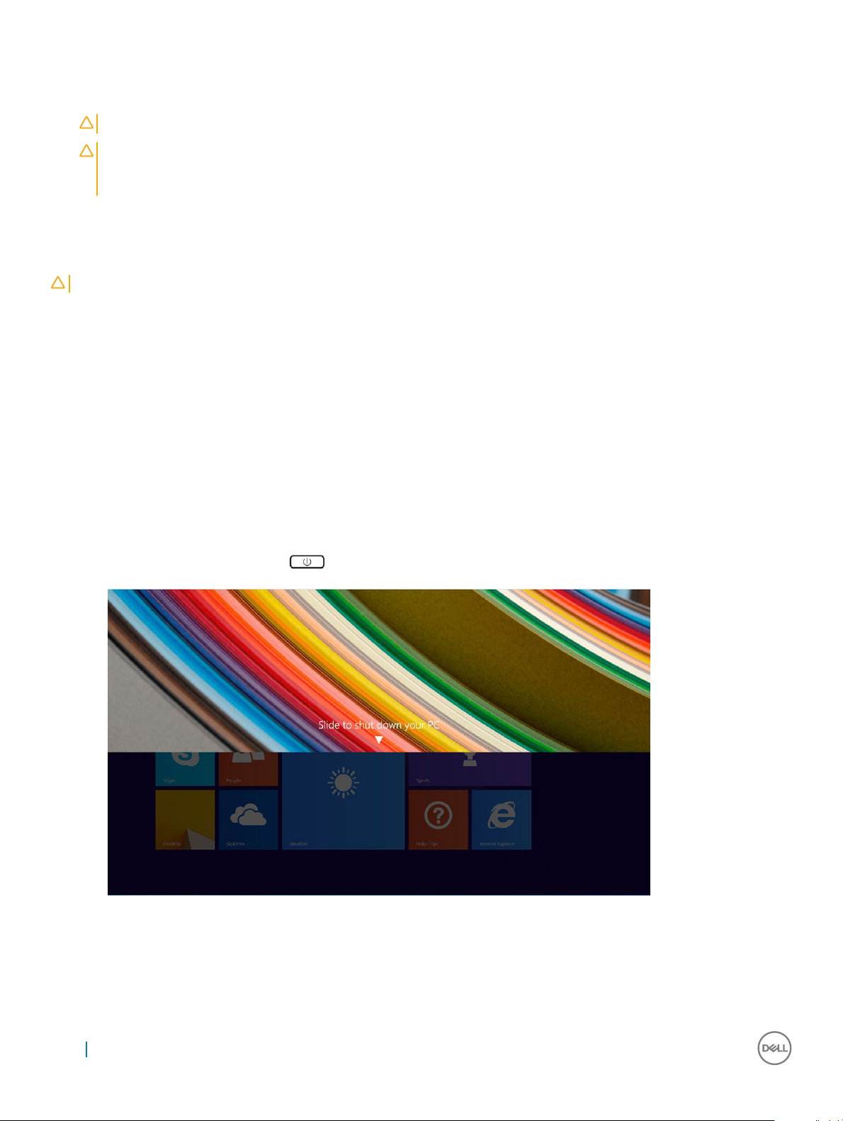
Turning o Your Tablet
Turning o your tablet completely shuts down your tablet. You can turn o your tablet by two ways:
• Using power button
• Using charms menu
1 To turn o your tablet using power button:
a Press and hold the Power button until you see “Slide to shut down your PC” on the screen.
Working on your computer
6
Page 7
NOTE: After you press and hold the Power button, by default, the “Slide to shut down your PC” screen displays only in
Venue 11 Pro 7130
However, if you change the power button setting to shut down, the tablet shuts down. To change the power button
setting, go to Control Panel > Power Options > Change Plan Setting > Change Advanced Power Settings. To access
Control Panel, swipe at the right edge of the screen, tap Search, enter Control Panel in the search box, and then click
Control Panel.
b Slide to shut down your tablet.
NOTE: You can also turn o your tablet without sliding down the screen. Press and hold the Power button for >10
seconds to turn o your tablet. You can perform this force shutdown, if your tablet is not responding / behaving
unexpectedly or touch is not working.
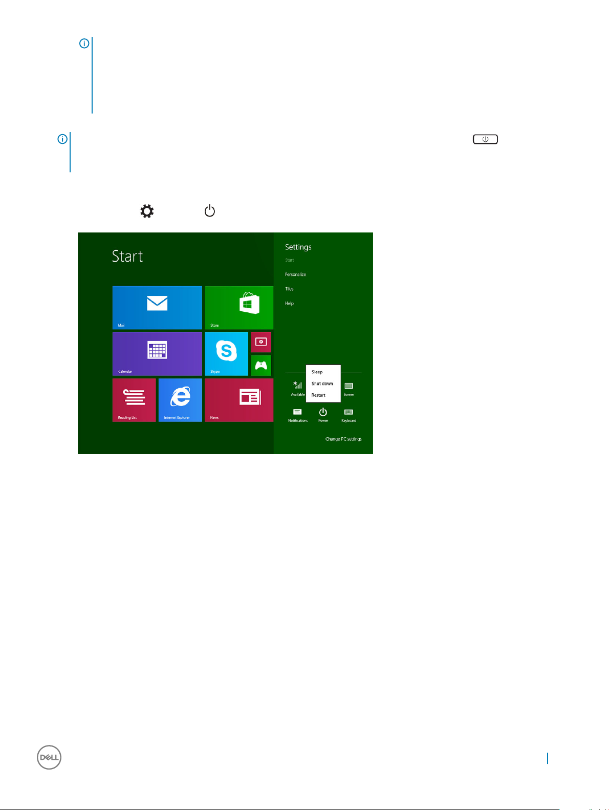
2 To turn o your tablet using the charms menu:
a Swipe from the right edge of the display to access the Charms menu.
Touch Settings —> Power —> Shut down to turn o the tablet.
b
. For
Venue 11 pro 7130 vPro
and
Venue 11 Pro 7139
, by default, the tablet enters sleep mode.
Working on your computer
7
Page 8

Removing and installing components
This section provides detailed information on how to remove or install the components from your computer.
Recommended tools
The procedures in this document may require the following tools:
• Phillips screwdriver
• #0 Phillips head screwdriver
• #1 Phillips head screwdriver
• Plastic scribe
Screw list
Table 1. Latitude 5285 2-in-1 Screw size list
Component M2.0x 1.1+1.7 M2.0X4.0 M1.6x3.0 M2.0X2.5 M1.6x3.0 M2.0X2.0 M2.0X3.5
2
Back cover 3
Battery 4
Heat sink 4
Hinges 4
Display panel 6
System fan 2
WWAN card 1
WLAN card 1
Smart card cage 3
SSD card 1
Docking bracket 2
Kickstand 4
Camera module 3
Antenna module 1
System board 4
Removing and Installing components
This section provides detailed information on how to remove or install the components from your tablet.
8 Removing and installing components
Page 9
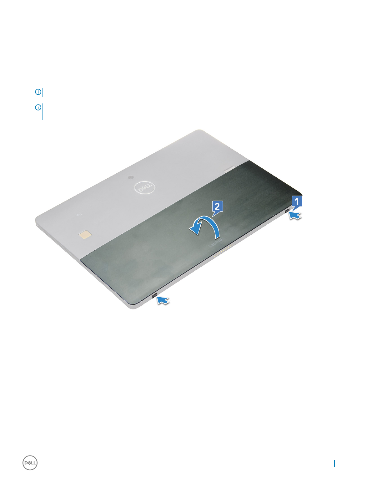
micro SD - micro SIM card
uSIM cards can be installed only on tablets shipped with WWAN module.
1 Flip the tablet on a plane and at surface.
2 Press the two Kickstand auto-release pegs, and slide the kickstand [1],[2].
NOTE: Or Pull and slide the kickstand to open, ensure NOT to pull more than 135° to avoid damage to the hinges.
NOTE: Ensure to turn o or disconnect power, to drain ea power before installing the micro SD and/or micro-
SIM.
3 Slide the kickstand to an angle 135°, to microSD and micro-SIM cards slot.
4 Slide the microSD / micro-SIM card cover towards 3° clock [1] and pull the cover [2].
5 Insert the SD card / micro-SIM cards and a lign the cover with the groove on the tablet and slide it inside to secure the microSD and
the micro-SIM cards.
Removing and installing components
9
Page 10
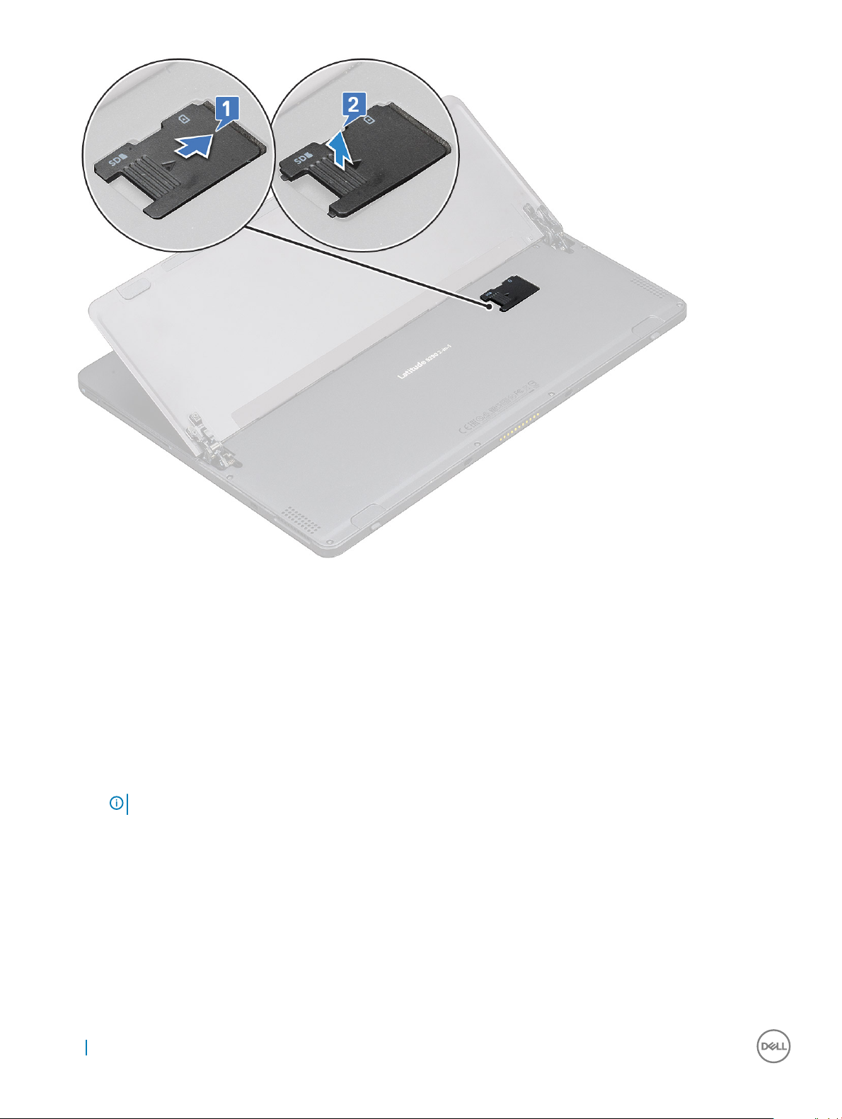
6 Perform the same steps to remove the microSD / micro-SIM cards
Display Assembly
Removing the display assembly
1 Follow the procedure in Before working inside your tablet.
2 Remove the:
a uSIM/microSD card
NOTE
: uSIM card slot is available only on tablets shipping with WWAN module.
3 Open the kickstand by holding the tablet vertically and pressing it down. Place the tablet with the display facing down.
10
Removing and installing components
Page 11
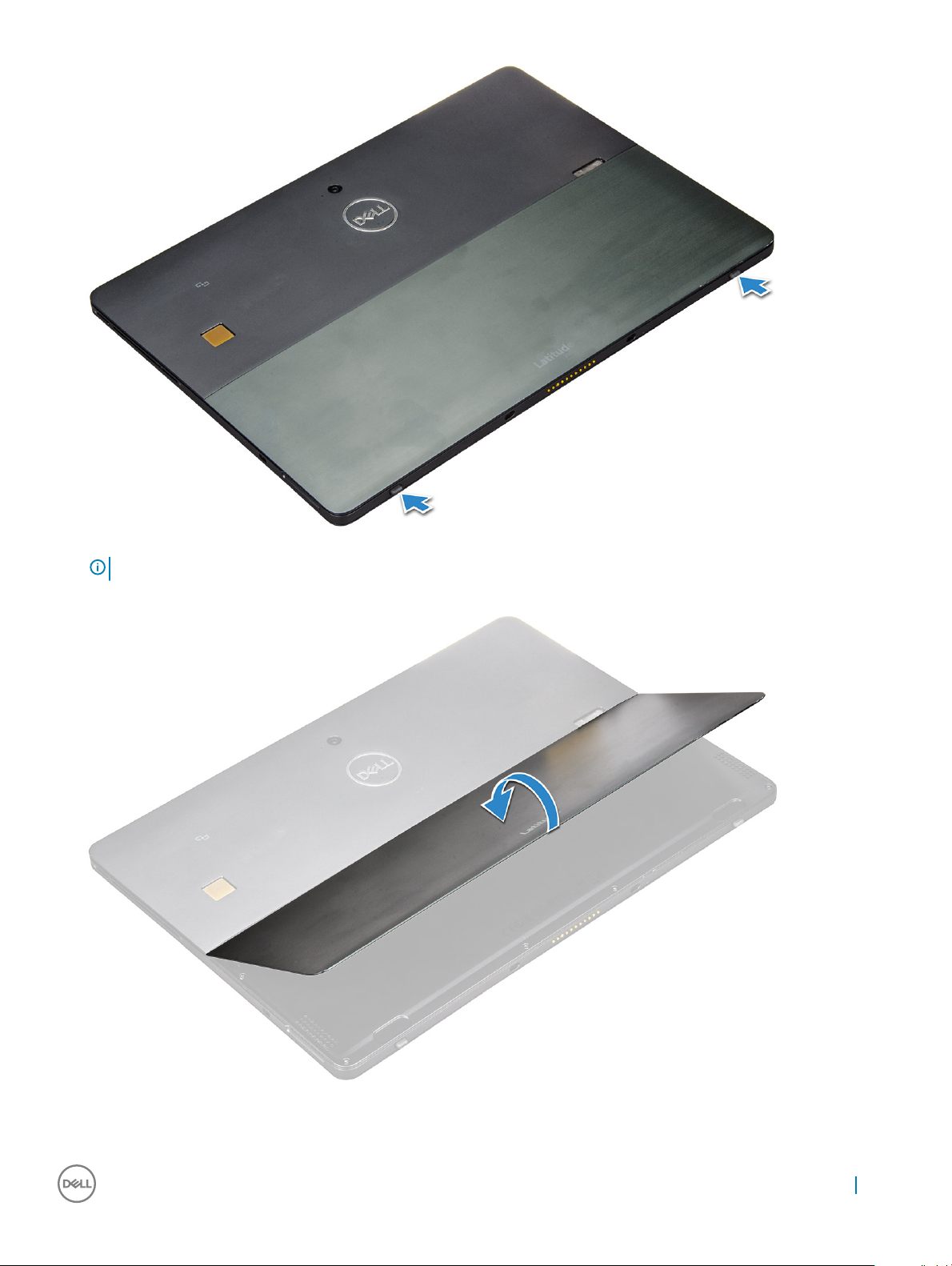
NOTE: You can also open the kickstand from the speaker recess area.
4 Place the tablet on a at surface and lift the stand to reveal the base of the tablet.
5 To release the display assembly:
a Remove the M1.6 x 3.0 (6) screws that secure the base cover to the tablet [1].
Removing and installing components
11
Page 12
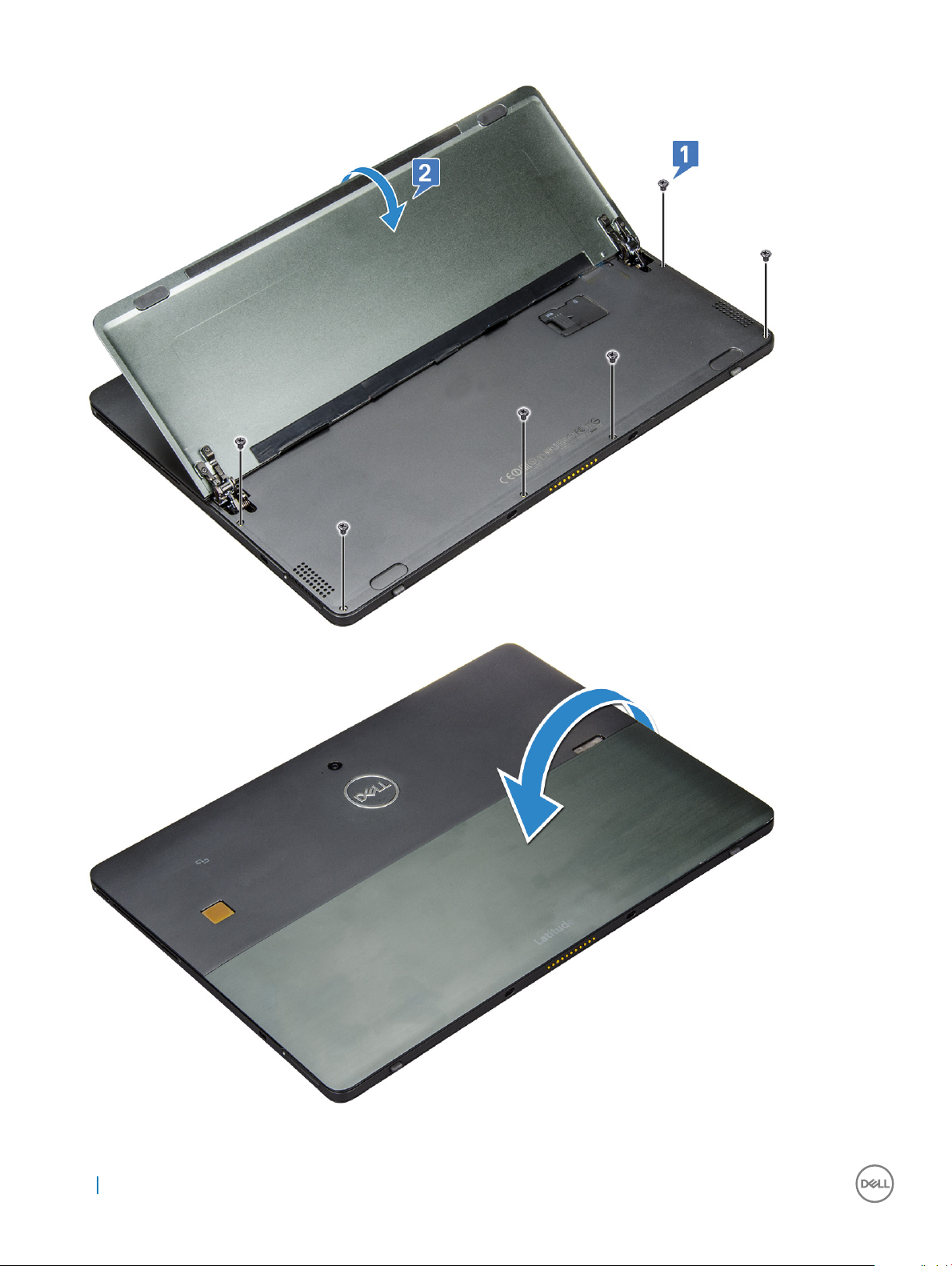
b Close the kickstand [2] and ip the tablet to view the display.
6 Use a plastic scribe [1] to pry the edges [2] of the display panel starting from the bottom side rst (near the docking port).
12
Removing and installing components
Page 13
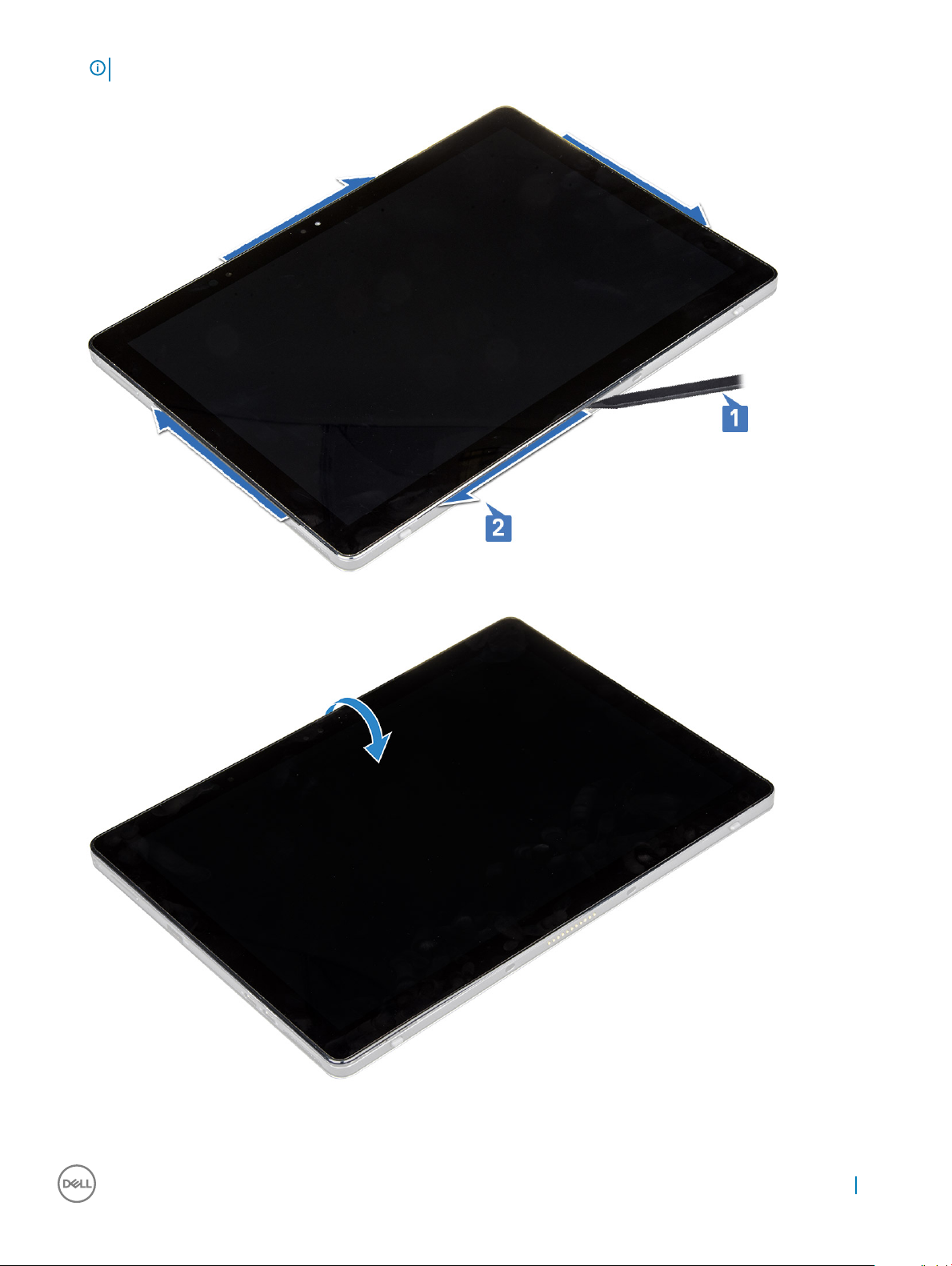
NOTE: Ensure to pry from the docking port and gently moving clockwise to avoid damage to the plastic clips.
7 Flip the display panel on a plane surface with the LCD panel upwards.
8 To disconnect the cables:
a Push and disconnect the battery cable on the system board [1].
Removing and installing components
13
Page 14
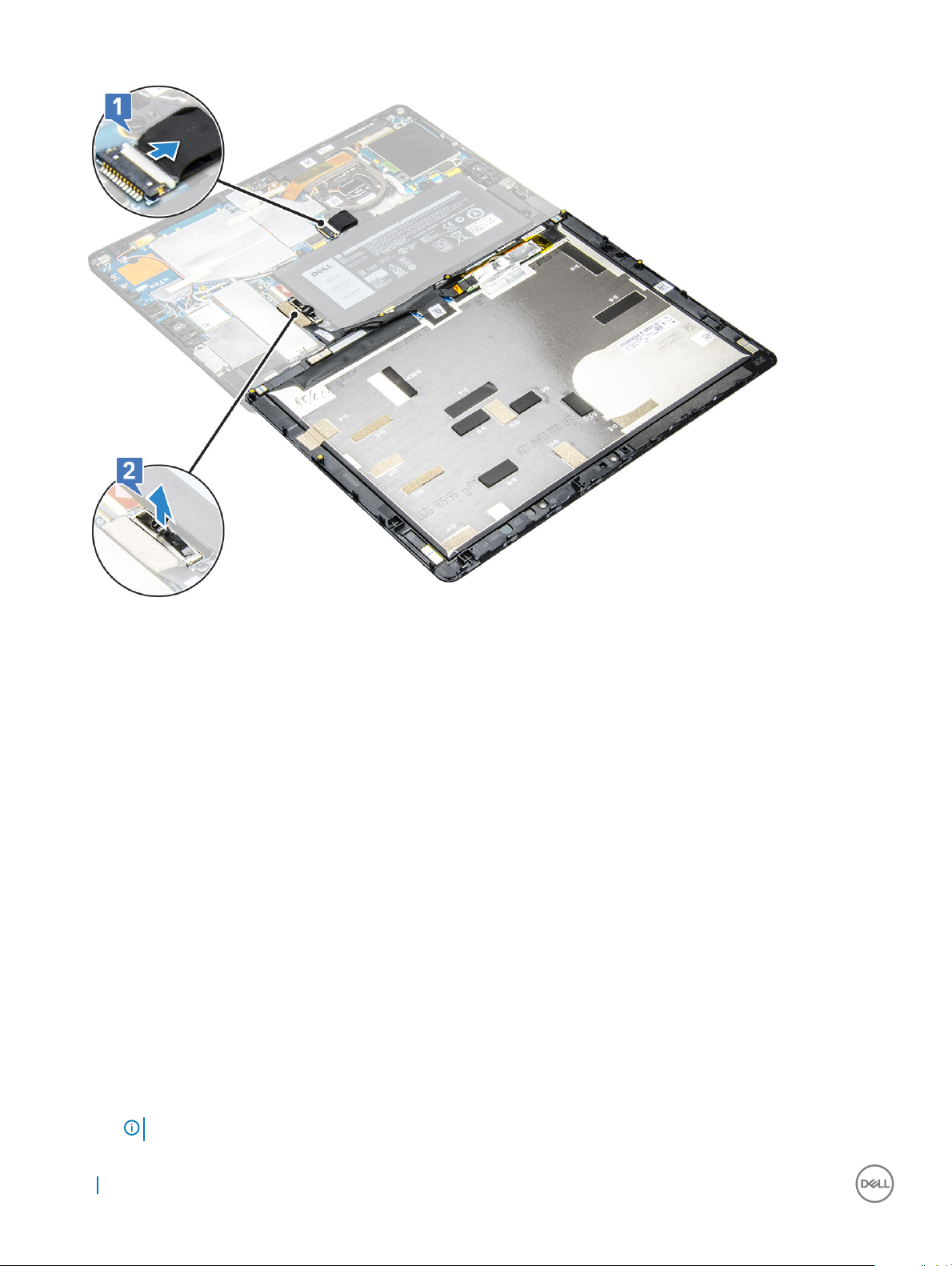
b Pull and disconnect the display cable on the system board [2].
9 Lift the display assembly from the tablet.
Installing the display assembly
1 Place the display panel on a plane surface.
2 Connect the display cable to the connector on the system board
3 Connect the battery cable to the connector on the system board.
4 Install the display panel on the tablet and press the edges until they snap in.
5 Flip the tablet and open the kickstand.
6 Replace the M1.6 x 3.0 screws to secure the tablet to the display panel.
7 Install the:
a uSIM/micro SD card
8 Follow the procedure in After working inside your tablet.
PCIe Solid State Drive (SSD)
Removing the SSD module
1 Follow the procedure in Before working inside your tablet.
2 Remove the:
a uSIM/microSD card
: uSIM card slot is available only on tablets shipping with WWAN module.
NOTE
14 Removing and installing components
Page 15
b display panel
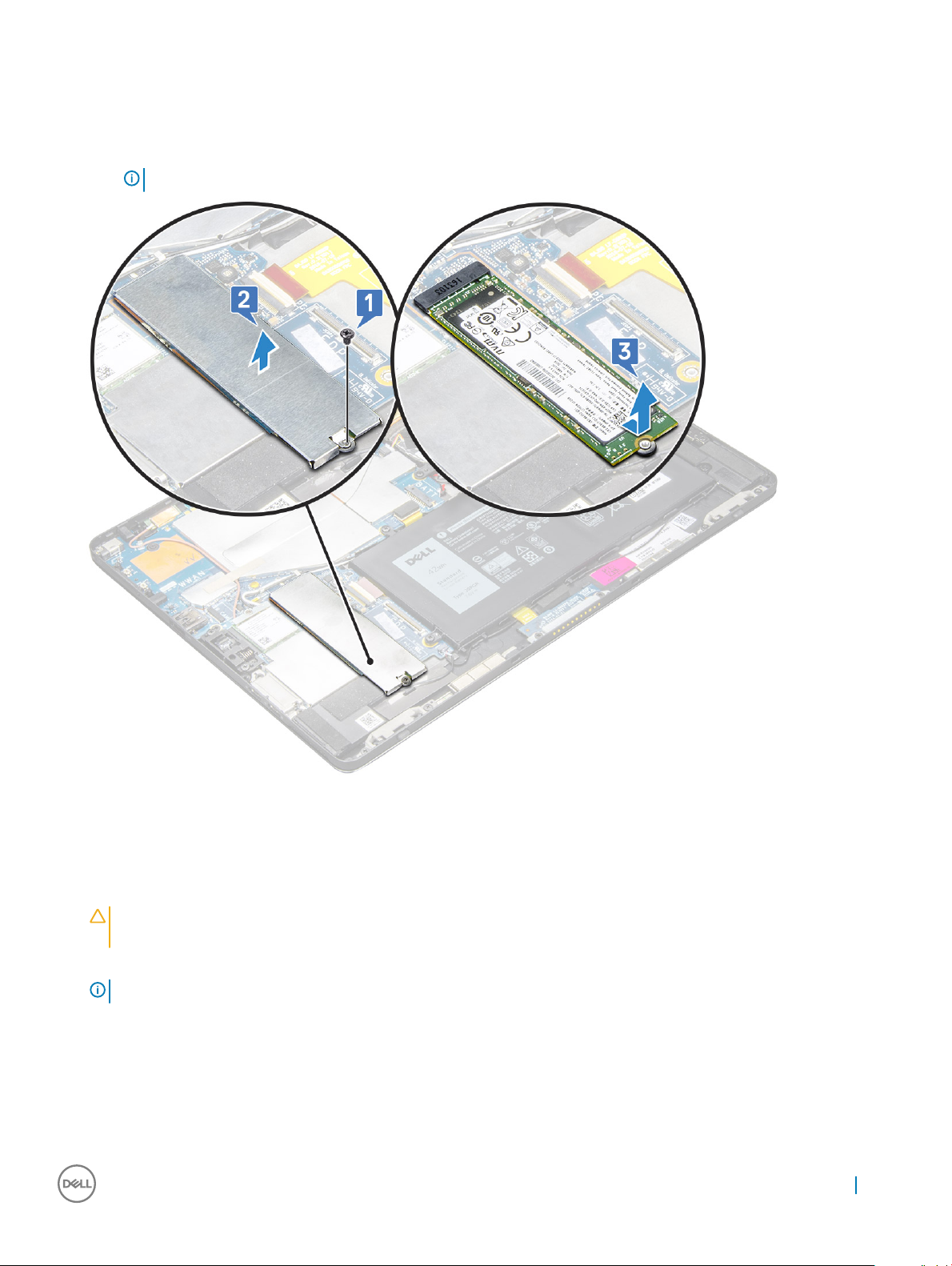
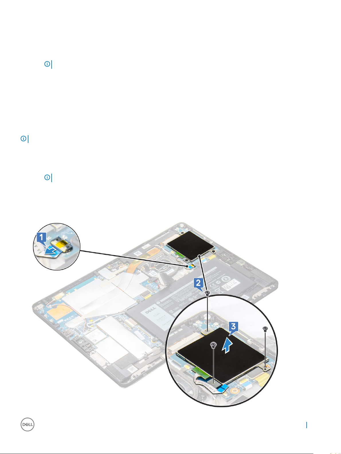
3 To remove the SSD module:
a Remove the M2.0 x 2.5 screw securing the SSD shield [1].
b Lift the SSD shield away from the tablet [2].
c Slide and lift the SSD module from the slot on the tablet [3].
NOTE: Ensure NOT to lift the SSD card by an angle more than 15°.
Installing SSD module
1 Insert the SSD module into the connector on the system board.
2 Install the SSD shield on the SSD module.
CAUTION
with caution, as the clips are small and delicate. Mishandling damages the clips head and needs replacing the shield.
3 Replace the M2.0 x 2.5 screw to secure SSD shield.
NOTE
4 Install the:
a Display panel
b uSIM/microSD
Micro-SIM card is installed only on tablets shipped with WWAN module.
5 Follow the procedure in after working inside your tablet.
: Align the ve clips heads into the system board clips holes, to install the shield properly. Ensure to insert the clips
: Align the shield carefully to avoid damage to the clips heads.
Removing and installing components
15
Page 16
WLAN card
Removing the WWAN card
1 Follow the procedure in Before working inside your tablet.
2 Remove the:
a uSIM/micrSD card
NOTE: uSIM card slot is available only on tablets shipping with WWAN module.
b display panel
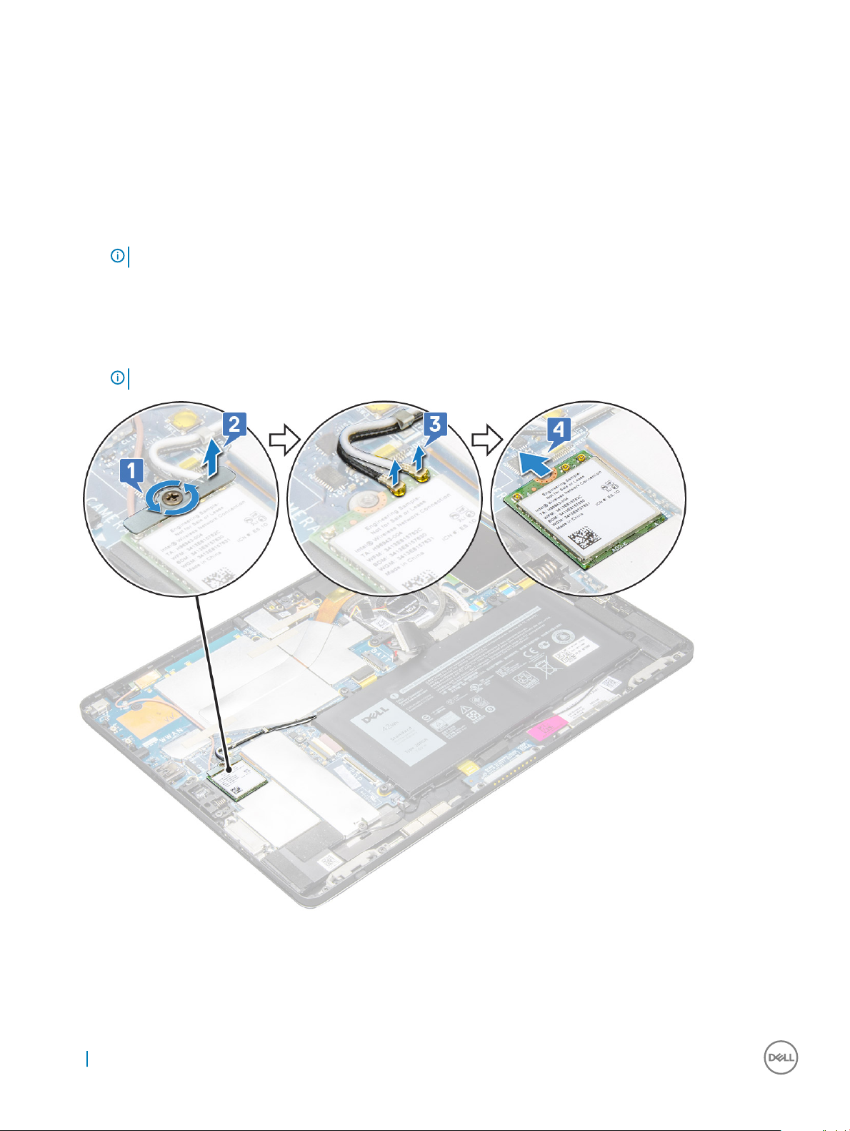
3 To remove the WWAN card:
a Remove the M2.0 x 3.5 screw securing the WWAN bracket [1] and lift the bracket [2].
b Disconnect the antenna cables from the WWAN card [3].
c Lift and slide the WLAN card from the connector on the system board [4].
NOTE: Ensure to lift the WWAN card by an angle NOT more than 20°.
Installing the WLAN card
1 Insert the WLAN card into the connector on the system board.
2 Connect the antenna cables to the WLAN card.
16
Removing and installing components
Page 17
3 Insert the WLAN bracket to the WLAN card.
4 Replace the M2.0 x 3.5 screw to secure WLAN bracket.
5 Install the:
a display panel
b uSIM/microSD
NOTE: uSIM card is installed only on tablets shipping with WWAN module.
Follow the procedure in After working inside your tablet.
6
Speaker
Removing the speaker
1 Follow the procedure in Before working inside your tablet.
2 Remove the:
a Micro SIM/micro SD card
NOTE: Micro SIM card slot is available only on tablets shipping with WWAN module.
b display panel
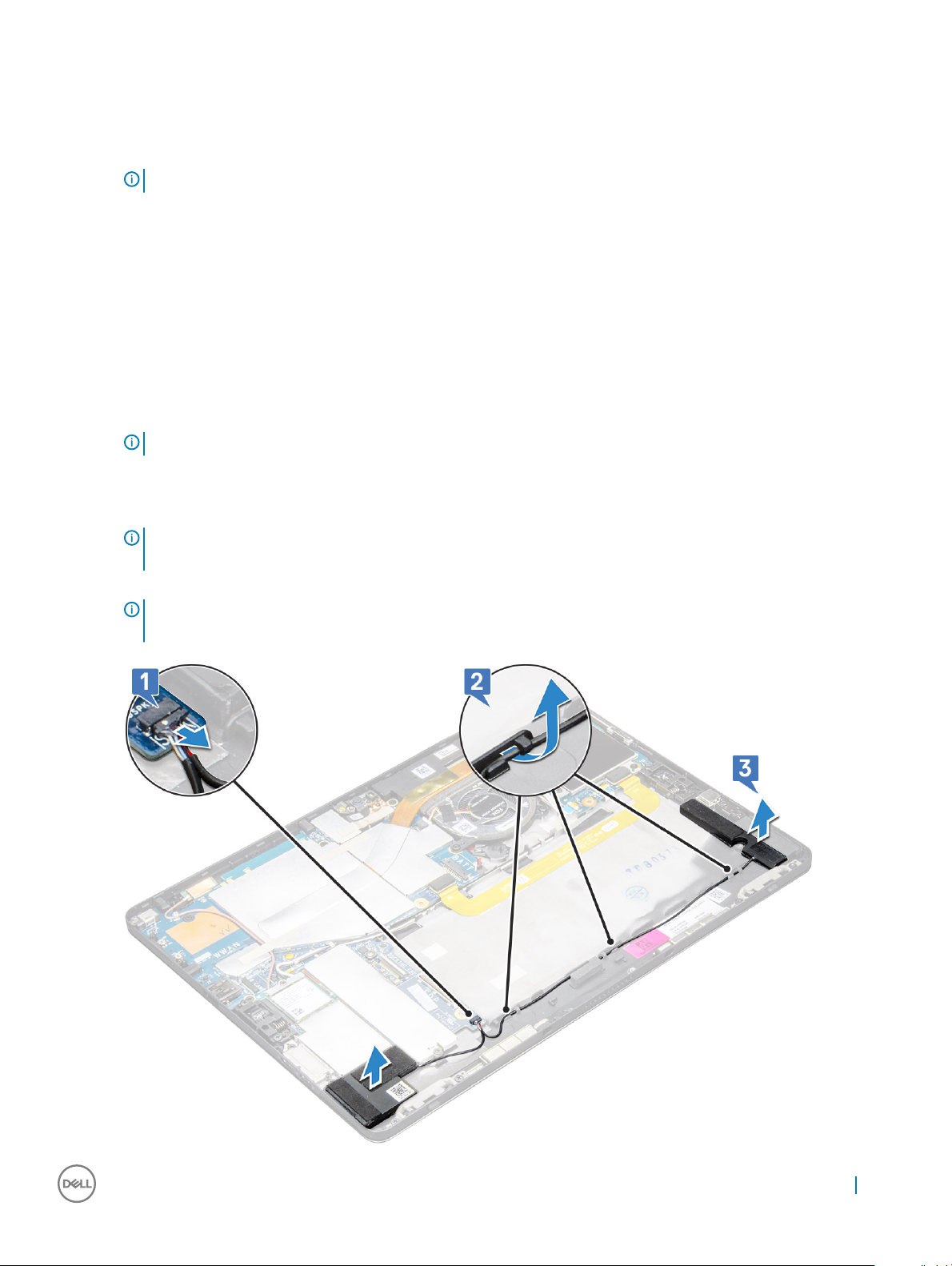
3 To remove the speaker:
a Lift the latch and release the speaker cable from the connector [1].
NOTE
: Ensure to remove the SSD, to create more space to pry o the
speakers.
b Un-route the speaker cable from the routing clips with a plastic scribe [2].
NOTE
: Ensure to remove the M.2 2280 SSD and M.2 2280 SSD shielding cover, to avoid obstruction in un-routing the
speaker cable.
Removing and installing components 17
Page 18

c Release the speakers from the tablet [3].
NOTE: The speaker is attached with an adhesive, ensure to pull gently for reuse of the tape in installing the speaker.
Installing speaker
1 Insert the speaker in the block on the system board.
2 Connect the cables to the system board.
3 Press the speaker to glue it to the adhesive paste on the system.
4 Install the:
a Display panel
b uSIM/microSD
NOTE: uSIM card is installed only on tablets shipping with WWAN module.
5 Follow the procedure in After working inside your tablet.
Battery
Removing the battery
1 Follow the procedure in Before working inside your tablet.
2 Remove the:
a uSIM/micro SD card
NOTE
: uSIM card slot is available only on tablets shipping with WWAN module.
b display panel
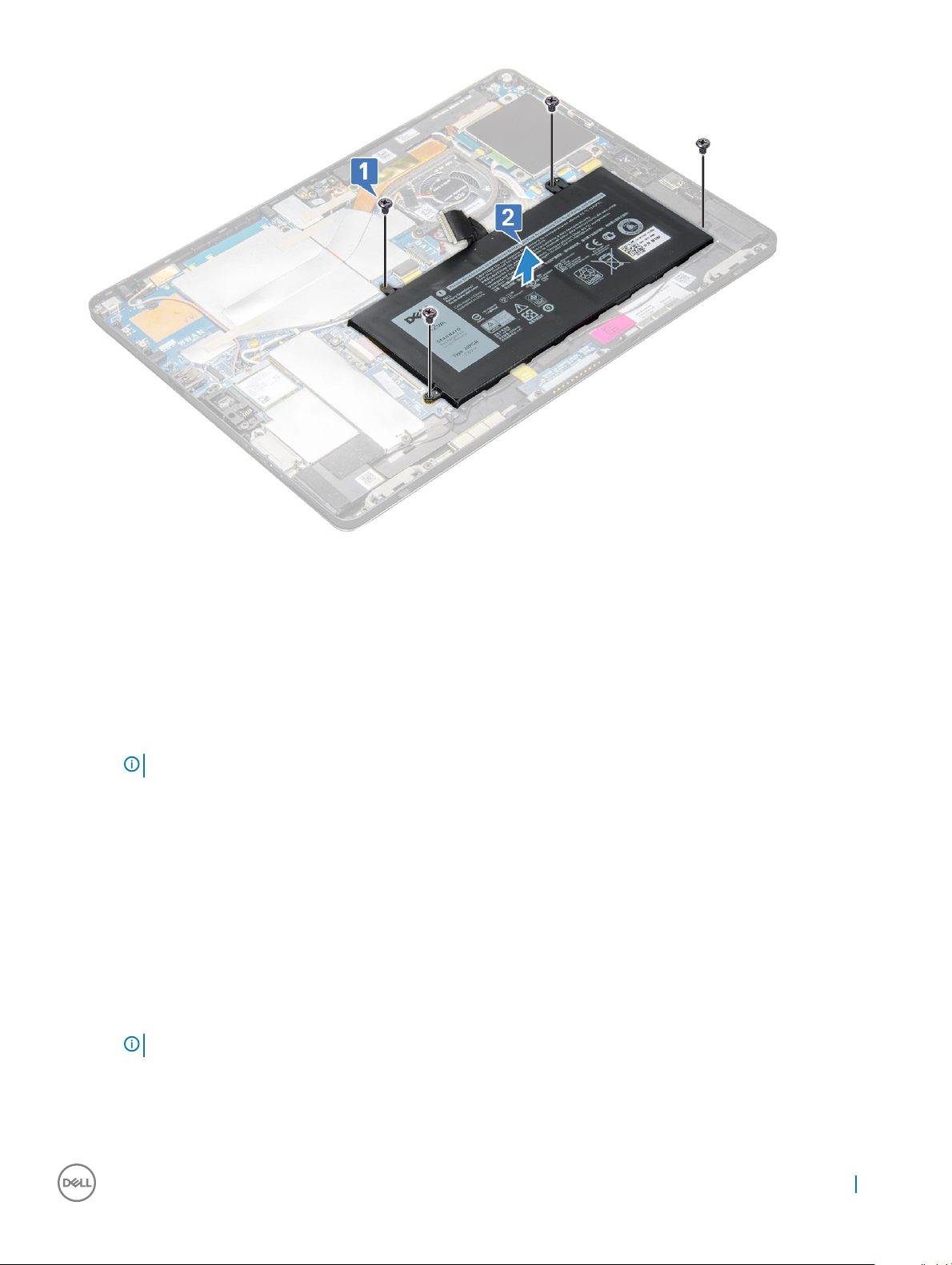
3 To remove the battery:
a Release the adhesive tape that secures the battery connector to the system board.
b Disconnect the battery cable from the connector on the system board.
NOTE
: Ensure to pull the cable by the lever of the battery connector, to avoid damage to the pin.
c Remove the M2.0 x 4.0 screws (4) that secure the battery to the tablet [1].
d Lift the battery from the tablet [2].
18
Removing and installing components
Page 19
Installing the battery
1 Insert the battery into the slot on the tablet.
2 Replace the M2.0 x 4.0 screws to secure the battery to the tablet.
3 Connect the battery connector to the system board and release the adhesive tape that secures the connector.
4 Install the:
a display panel
b uSIM/microSD card
NOTE
: uSIM card is installed only on tablets shipping with WWAN module.
5 Follow the procedure in After working inside your tablet.
System Fan
Removing the system fan
1 Follow the procedure in Before working inside your tablet.
2 Remove the:
a uSIM/microSD card
: Micro-SIM card slot is available only on tablets shipped with WWAN module.
NOTE
b Display panel
3 To remove the system fan:
a Disconnect the system fan cable from the system board [1].
b Remove the M2.0 x 4.0 screws (2) that secure the system fan [2].
Removing and installing components
19
Page 20
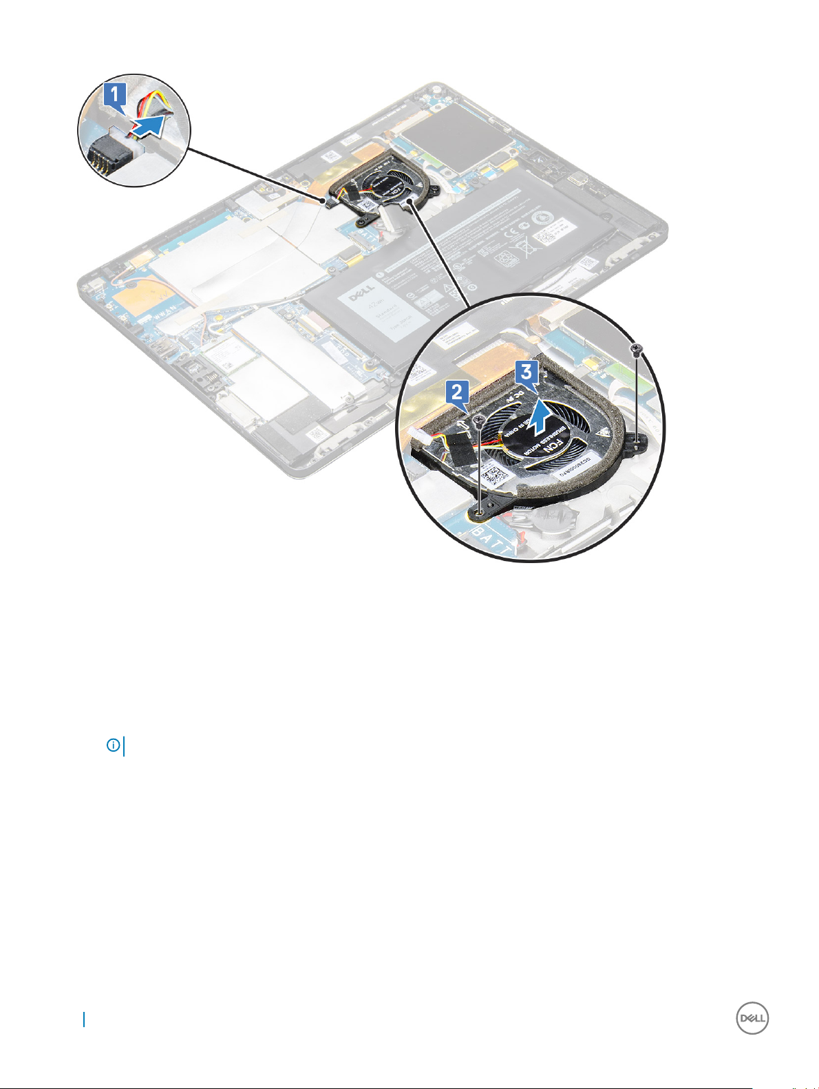
c Lift the system fan from the tablet system chassis [3].
Installing the system fan
1 Align the system fan with screw holders on the system board.
2 Replace the M2.0 x 3.0 screws to secure the system fan to the system board.
3 Connect the system fan cable to the system board.
4 Install the:
a display panel
NOTE
: uSIM card is installed only on tablets shipping with WWAN module.
b uSIM/microSD card
5 Follow the procedure in After working inside your tablet.
Heat Sink
Removing heat sink assembly
1 Follow the procedure in Before working inside your tablet.
2 Remove the:
a Micro-SIM and/or microSD card
20
Removing and installing components
Page 21
NOTE: Micro-SIM card slot is available only on tablets shipping with WWAN module.
b Display panel
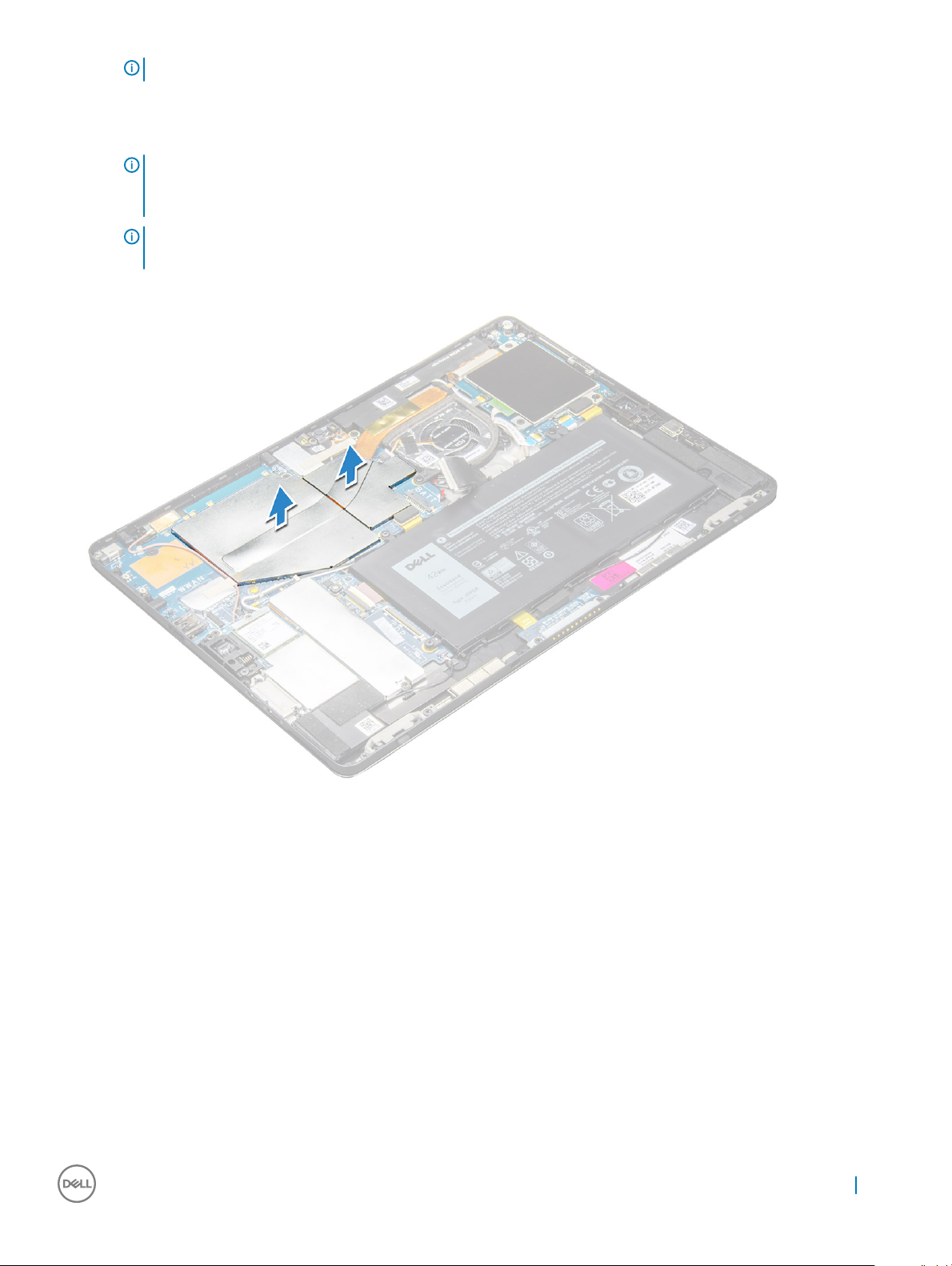
3 To remove the heat sink assembly:
a Peel the conductive tapes that secure the shielding cover.
NOTE: Ensure to peel o the tape carefully, as any damage to the tape will need to raise a new order for conductive
tapes. The tape secures the IR camera cable from any damage. Ensure to x the tapes while installing or replacing the
component.
NOTE: Ensure to peel o the conductive tape, if the system heatsink is shipped with a
tape.
b Lift the shielding covers that secure the heat sink assembly .
4 To remove the heat sink assembly:
a Loosen the M2.0 x 2.5 captive screws (4) that secure the heat sink assembly to the tablet [1].
b Lift the heat sink assembly from the tablet [2].
Removing and installing components
21
Page 22

Installing heat sink assembly
1 Align the heat sink assembly with screw holders on the system board.
2 Replace the M2.0 x 2.5 screws to secure the heat sink to the system board.
NOTE
: Tighten the screws on the system board in the order of the callout numbers [1, 2, 3, 4] as indicated on the heat sink.
3 Install the shielding covers on the heat sink assembly.
4 Ax the conductive tapes to secure the shielding covers.
5 Replace the shielding covers to cover the heat sink assembly.
NOTE
: The shield covers can break if not handled carefully.
6 Install the:
a display panel
b uSIM/microSD card
NOTE
: uSIM card is installed only on tablets shipping with WWAN module.
7 Follow the procedure in After working inside your tablet
Front facing camera
Removing front camera
1 Follow the procedure in Before working inside your tablet.
2 Remove the:
a Micro-SIM and/or microSD card
22
Removing and installing components
Page 23
NOTE: Micro-SIM card slot is available only on tablets shipping with WWAN module.
b Display panel
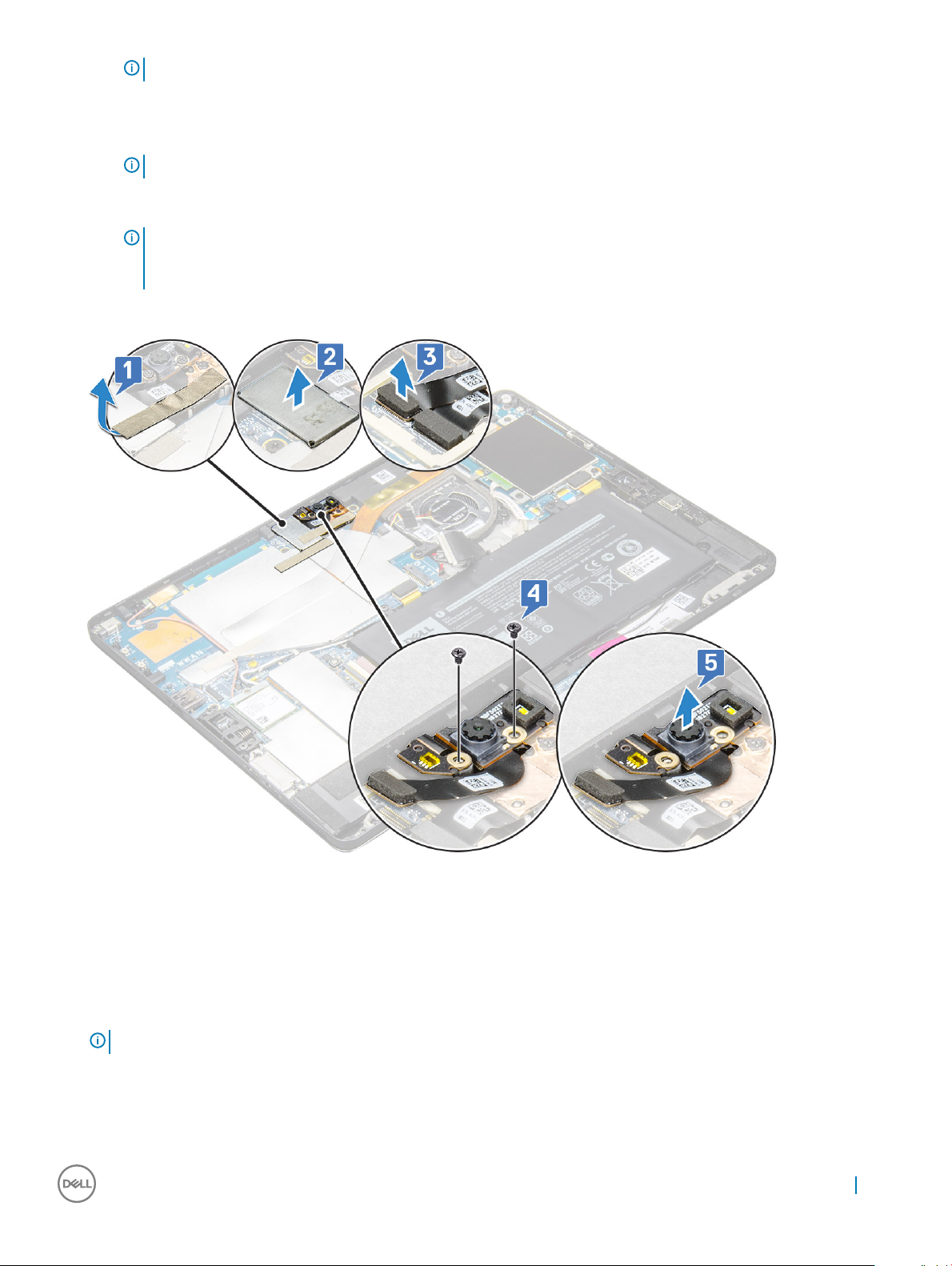
3 To remove the front camera:
a Remove the conductive tape covering the shielding cover [1].
NOTE: Ensure to pull the conductive tape gently to reuse in installing the front camera.
b Lift the shielding cover covering the front cameracable connected to the system board[2].
c Use a plastic scribe to disconnect the front camera cable [3]
NOTE: Ensure to peel o the adhesive tape that secures the front camera to the rear camera. The front camera cable
is glued to the rear camera, ensure to gently peel o, to remove the screw that secures the rear camera to the system
board.
d Remove the M1.6 x 3.0 screws (2) securing the front camera module [4].
e Lift the front camera module from the tablet [5].
Installing the front camera
1 Insert the camera module into the slot on the tablet.
2 Replace the M1.6 x 3.0 screws to secure the front camera module.
3 Connect the front camera cable to the system board.
4 Place the covering shield to cover the front camera module.
: Handle the covering shield with care else it may break.
NOTE
5 Ax the tape to secure the shield cover.
6 Install the:
a display panel
b uSIM/microSD card
Removing and installing components
23
Page 24
NOTE: uSIM card is installed only on tablets shipping with WWAN module.
7 Follow the procedure in After working inside your tablet.
Rear facing camera
Removing rear camera
1 Follow the procedure in Before working inside your tablet.
2 Remove the:
a uSIM/microSD
NOTE: Micro-SIM card slot is available only on tablets shipping with WWAN module.
b Display panel
c front facing camera
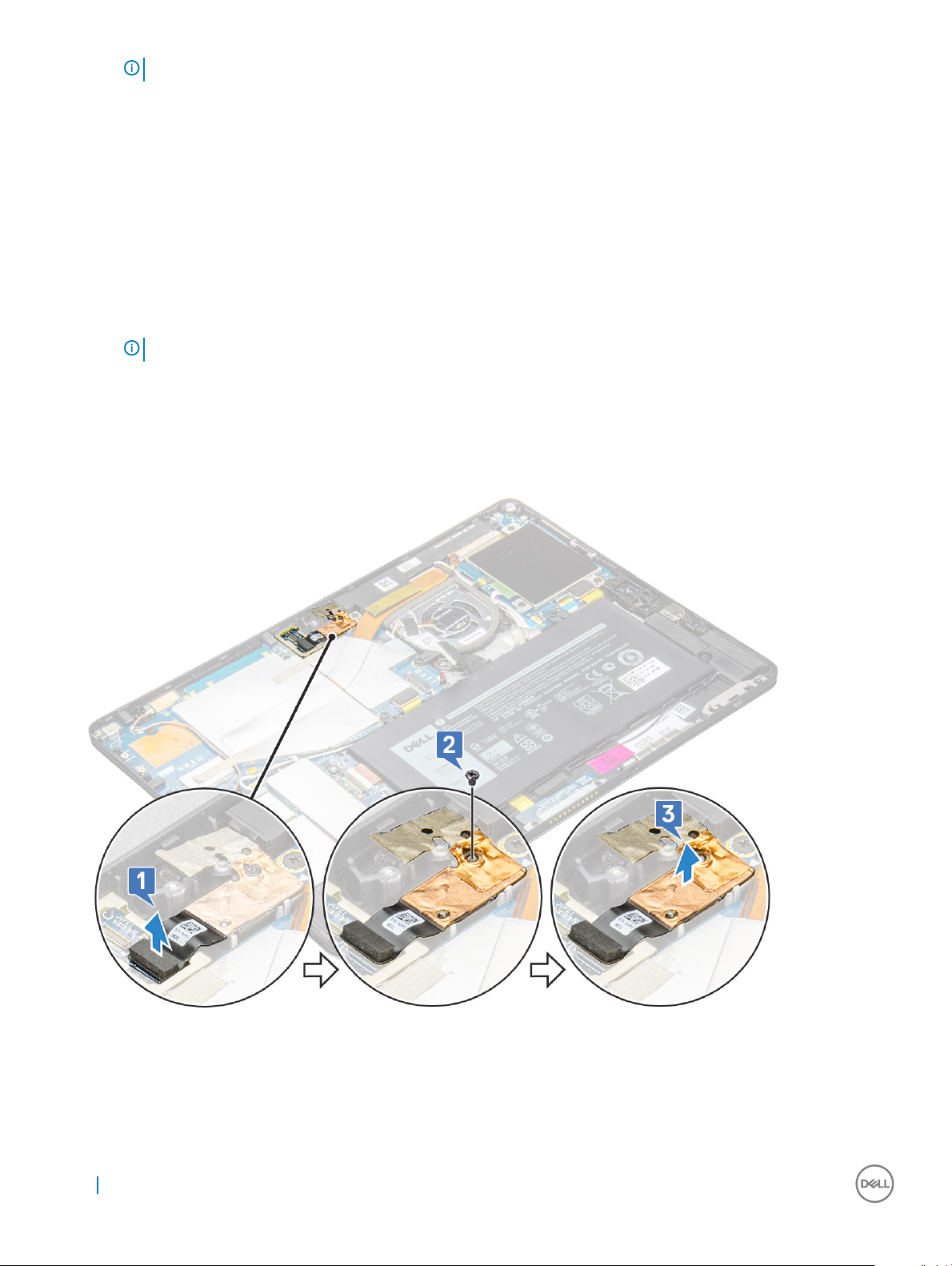
3 To remove the rear camera:
a Disconnect the rear camera cable from the system board [1].
b Remove the M1.6 x 3.0 screw (1) securing the rear camera module [2].
c Lift the camera module from the tablet [3].
Installing the rear camera
1 Insert the rear camera module into the slot on the tablet.
2 Replace the M1.6 x 3.0 screw to secure the rear camera module.
24
Removing and installing components
Page 25
3 Connect the rear camera cable to the system board.
4 Install the:
a front camera
b display panel
c uSIM/microSD
NOTE: uSIM card is installed only on tablets shipping with WWAN module.
5 Follow the procedure in After working inside your tablet.
Smart Card Cage
Removing the smart card cage
NOTE: Always remove the smart card from the smart card reader.
1 Follow the procedure in Before working inside your tablet.
2 Remove the:
a uSIM/microSD card
NOTE: uSIM card slot is available only on tablets shipping with WWAN module.
b display panel
3 To disconnect the cables:
a Lift the latch and dDisconnect the smart card cable from the smart card cage [1].
b Remove the M2.0 x 2.5 screws (3) from the smart card module [2].
c Lift the smart card cage from the tablet [3].
Removing and installing components
25
Page 26

Installing the smart card cage
1 Insert the smart cage into the slot on the tablet.
2 Replace the M2.0 x 2.5 screws screws to secure the smart card cage to the tablet.
3 Connect the smart cable to the smart card module.
4 Install the:
a display panel
b uSIM/microSD card
NOTE: uSIM card is installed only on tablets shipping with WWAN module.
5 Follow the procedure in After working inside your tablet.
Docking board
Removing the docking board
1 Follow the procedure in Before working inside your tablet.
2 Remove the:
a uSIM/microSD card
NOTE
: uSIM card slot is available only on tablets shipping with WWAN module.
b display panel
c battery
3 To release the docking board:
a Lift the latch and dDisconnect the docking board cable from the system board [1].
b Peel the docking board cable from adhesive on the tablet [2].
c Remove the M2.0 x 2.0 screws (2) securing the docking board bracket to the docking board [3].
d Lift the docking board from the tablet [4].
26
Removing and installing components
Page 27

Lift the docking board after releasing the cable from the adhesive.
Removing and installing components
27
Page 28

Installing the docking board
1 Insert the docking board into the slot on the tablet.
2 Replace the M2.0 x 2.0 screws to secure the docking board to the tablet.
3 Ax the docking board cable on the tablet,
4 Connect the docking board cable to the connector on the system board.
5 Install the:
a battery
b display panel
c uSIM/microSD card
NOTE: uSIM card is installed only on tablets shipping with WWAN module.
6 Follow the procedure in After working inside your tablet.
System Board
Removing system board
1 Follow the procedure in Before working inside your tablet.
2 Remove the:
a uSIM/microSD card
NOTE
: Micro-SIM card slot is available only on tablets shipping with WWAN module.
b display panel
c battery
d SSD card
e WLAN card
f system fan
g front camera
h rear camera
i heat sink
3 Disconnect the following cables from the system board .
a docking board cable [1]
NOTE
: Lift the latch and disconnect the docking board cable.
b speaker cable [2]
c USH board cable [3]
28
Removing and installing components
Page 29

4 Un route the antenna cables from the routing clips [1,2,3].
5 To remove the system board
a Remove the bracket M2.0 x 2.5 screws (2) and lift the bracket form the tablet [1],[2].
b Release the coin cell battery from the adhesive on the tablet chassis [3].
Removing and installing components
29
Page 30

c Remove the M2.0 x 2.5 screws (4) that secure the system board to the tablet [1].
d Lift the system board from the tablet [2].
30
Removing and installing components
Page 31

Installing system board
1 Align the system board with the screw holders on the tablet.
2 Tighten the M2.0 x 2.5 screws to secure the system board to the tablet.
NOTE: Remember to align the Type-C port and tighten the two screws to secure the port to the system chassis.
Route the antenna cables through the routing clips and channels.
3
4 Connect the docking board cable, speaker cable and the USH board cable to the connectors on the system board.
5 Install the:
a heat sink
b rear facing camera
c front facing camera
d system fan
e WLAN card
f SSD card
g battery
h display panel
i uSIM/microSD
NOTE: uSIM card is installed only on tablets shipping with WWAN module.
6 Follow the procedure in After working inside your tablet.
Real time clock (RTC)
Removing the RTC battery
RTC battery connector is located beneath the system board.
1 Follow the procedure in Before working inside your tablet.
2 Remove the:
a uSIM and/or microSD card
NOTE
: uSIM card slot is available only on tablets shipping with WWAN module.
b display panel
c battery
d system board
3 To remove the RTC battery:
a Disconnect the RTC battery cable from the connector beneath the system board.
b Lift the RTC battery from the tablet.
Removing and installing components
31
Page 32

NOTE: If you can easily disconnect the RTC battery cable from beneath the connector on the system board, you need not
remove the system board to remove the RTC battery.
Installing the RTC battery
1 Insert the RTC battery to the slot on and ax it to the back cover.
2 Connect the RTC battery cable to the connector beneath the system board.
3 Install the:
a battery
b display panel
c uSIM/microSD card
NOTE
: uSIM card is installed only on tablets shipping with WWAN module.
4 Follow the procedure in After working inside your tablet.
USH board
Removing the USH board
1 Follow the procedure in Before working inside your tablet.
2 Remove the:
a uSIM/microSD card
: uSIM card slot is available only on tablets shipping with WWAN module.
NOTE
b display panel
32
Removing and installing components
Page 33

c battery
d smart card cage
3 To disconnect the cables:
a Lift the shield from the connector on the USH board [1].
b Disconnect the NFC and ngerprint reader cables from the connectors on the USB board [2].
c Disconnect the USH board cable from the connector on the USH board [3]
d Remove the M2.0 x 2.5 screw that secures the USH board [4].
e Lift the USH board from the tablet [5].
Installing the USH board
1 Replace the USB board in the slot on the tablet.
2 Connect the M2.0 x 2.5 screw to secure the USH board
3 Connect the USH board cable to the connector on the USH board.
4 Connect the NFC and the ngerprint reader cables to the connectors on the system board.
5 Replace the shield on the USH board.
6 Install the:
a smart card cage
b battery
c display panel
d uSIM/microSD card
: uSIM card is installed only on tablets shipping with WWAN module.
NOTE
7 Follow the procedure in After working inside your tablet.
Removing and installing components
33
Page 34

Antenna
Removing the antenna module
1 Follow the procedure in Before working inside your tablet.
2 Remove:
a uSIM and/or microSD card
NOTE: uSIM card slot is available only on tablets shipping with WWAN module.
b display panel
c battery
d front facing camera
e rear facing camera
f system board
3 To un route the antenna cables of the antenna module:
a Peel the tape that secures the cables to the back cover of the tablet [1].
b Un route the cables from routing channels on the back cover
c Peel the conductive tape that secures the cables [3].
4 To remove the antenna module:
a Remove the M1.6 x 3 screw that secures the antenna module to the back cover of the tablet [1].
b Lift the antenna module from the back cover [2].
34
Removing and installing components
Page 35

Installing the antenna module
1 Insert the antenna module into the slot on the back cover of the tablet.
2 Tighten the M1.6 x 3 screw to secure the antenna module,
3 Un route the antenna cables from the routing channels,
4 Ax the tape and the conductive tapes to secure the antenna cables
5 Install the:
a heat sink
b rear facing camera
c front facing camera
d system fan
e WLAN card
f SSD card
g battery
h display panel
i uSIM/microSD card
: uSIM card is installed only on tablets shipping with WWAN module.
NOTE
6 Follow the procedure in After working inside your tablet.
Removing and installing components
35
Page 36

Technology and components
This chapter details the technology and components available in the system.
Topics:
• Power adapter
• Processors
• Chipset
• Memory features
• Display options
• Camera features
• Hard drive options
• Drivers
• Dell Active Pen
Power adapter
3
This system is shipped with 45 W or 65 W Type-C power adapters.
WARNING
pull rmly but gently to avoid damaging the cable.
WARNING: The power adapter works with electrical outlets worldwide. However, power connectors and power strips vary
among countries. Using an incompatible cable or improperly connecting the cable to the power strip or electrical outlet may
cause re or equipment damage.
: When you disconnect the power adapter cable from the tablet, grasp the connector, not the cable itself, and then
Processors
Latitude 5285 is shipped with:
• Intel Core i3-7100U (Dual Core, 3M cache, 2.4 GHz,15 W)
• Intel Core i5-7200U (Dual Core, 3M Cache, up to 3.1 GHz, 15 W)
• Intel Core i5-7300U (vPro, Dual Core, 3M Cache, up to 3.5 GHz, 15 W)
• Intel Core i7-7600U (vPro, Dual Core, 4M cache, up to 3.9 GHz, 15 W)
: The clock speed and performance varies depending on the workload and other variables.
NOTE
Kaby Lake — 7th Generation Intel Core processors
The 7th Gen Intel Core processor (Kaby Lake) family is the successor of 6th generation processors (Skylake). It's main features include:
• Intel 14nm Manufacturing Process Technology
• Intel Turbo Boost Technology
• Intel Hyper Threading Technology
• Intel Built-in Visuals
36 Technology and components
Page 37

• Intel HD graphics - exceptional videos, editing smallest details in the videos
• Intel Quick Sync Video - excellent video conferencing capability, quick video editing and authoring
• Intel Clear Video HD - visual quality and color delity enhancements for HD playback and immersing web browsing
• Integrated memory controller
• Intel Smart Cache
• Optional Intel vPro technology (on i5/i7) with Active Management Technology 11.6
• Intel Rapid Storage Technology
NOTE: Windows 7 and 8 are not supported by systems with 7th generation processors
Identifying processors in Windows 10
1 Type Device Manager in Ask me anything eld.
The Device Manager window is displayed.
2 Click Processor.
The processor information is displayed.
Figure 1. Processor
Verifying processor usage in task manager
1 Right click on the taskbar. Select Task Manager
2 You can also access the task manager by clicking CTRL+ALT+DEL keys.
The Windows Task Manager window is displayed.
3 Click the Performance tab in the Windows Task Manager window.
Technology and components
37
Page 38

Verifying processor usage in resource monitor
1 Right click the on tablet.
2 Select Start Task Manager.
The Windows Task Manager window is displayed.
3 Click the Performance tab in the Windows Task Manager window.
The processor performance details are displayed.
4 Click Open Resource Monitor.
38
Technology and components
Page 39

Chipset
The chipset is integrated on the processor.
Identifying chipset in device manager on Windows 10
: The Chipset information displayed is a generic image and may be dierent from what is displayed.
NOTE
1 Type Device Manager in the Ask me anything eld.
Device Manager window appears.
2 Expand System Devices and search for the chipset.
Technology and components
39
Page 40

Memory features
Latitude 5285 supports the following memory congurations:
• 4G 1866MHz LPDDR3 - Intel Core i3-7100U
• 8G 1866MHz LPDDR3 - Intel Core i5-7200U/ Intel Core i5-7300U
• 16G 1866MHz LPDDR3 - Intel Core i7-7600U
Verifying system memory in setup
1 Turn on or restart your notebook.
2 When the Dell logo appears, press F2.
Entering BIOS setup message appears.
3 On the left pane, select Settings > General > System Information,
The memory information is displayed on the right pane.
Verifying system memory
Windows 10
1 Click the Windows button and select All Settings > System .
2 Under System, click About.
Testing memory using ePSA
1 Turn on or restart your tablet.
2 Perform one of the following actions after the Dell logo is displayed:
• With keyboard—Press F12.
• Tablet only—Press Volume Up button before pressing the Power button to turn on the tablet. Once the power sequence is
initiated, you can release the Volume Up button and ePSA will launch.
The PreBoot System Assessment (PSA) is launched on your tablet.
NOTE
: If you wait too long and the operating system logo appears, continue to wait until you see the desktop. Turn o the
tablet, and try again.
3 Follow the steps in Running ePSA diagnostics.
Display options
This tablet is shipped with 12.3" 1920x1280 Touch with Corning Gorilla Glass, Antireective and Antismudge display.
Identifying display adapter
1 Type Device manager in the Ask me anything eld.
40
Technology and components
Page 41

The Display Manager window is displayed.
2 Expand the Display adapters.
The display adapter information is displayed.
Figure 2. display adapter
Changing the screen resolution
1 Right click on the desktop and select Display Settings.
2 Tap or click the Advanced display settings.
3 Select the required resolution from the drop-down list and tap Apply.
Camera features
This system is shipped with front facing camera with 5 MP and rear facing camera with 8 MP
Identifying the camera in Device Manager on Windows 10
1 In the Search box, type device manager, and tap to start it.
2 Under Device Manager, expand Imaging devices.
Starting the camera
To start the camera, open an application that uses the camera. For instance, if you tap the Dell webcam central software or the Skype
software that is shipped with the 2-in-1, the camera turns on. Similarly, if you are chatting on the internet and the application requests to
access the webcam, the webcam turns on.
Technology and components
41
Page 42

Starting the camera application
1 Tap or click the Windows button and select All apps.
2 Select Camera from the apps list.
3 If the Camera App is not available in the apps list, search for it.
42
Technology and components
Page 43

Hard drive options
This system supports M.2 SATA SSD, M.2 PCIe NVMe SSD, and M.2 PCIe NVMe SED.
Identifying the hard drive in the BIOS
1 Turn on or restart your laptop.
2 When the Dell logo appears, perform one of the following actions to enter the BIOS setup program:
• With keyboard — Tap F2 until the Entering BIOS setup message appears. To enter the Boot selection menu, tap F12.
• In tablet mode — Press the Volume Up button to display the F12 boot selection or press Volume Down button to enter BIOS
setup directly.
Hard drive is listed under the System Information under the General group.
Technology and components 43
Page 44

Drivers
This section lists the drivers associated with the components shipped with your tablet.
System drivers
Figure 3. System drivers
44
Technology and components
Page 45

Disk driver
Figure 4. Disk driver
Technology and components
45
Page 46

Sound, video and game controller drivers
Figure 5. Sound, video, and game controllers
46
Technology and components
Page 47

Storage controller drivers
Figure 6. Storage controllers
Technology and components
47
Page 48

Network drivers
Figure 7. Network drivers
Graphics driver
Figure 8. Graphics driver
48
Technology and components
Page 49

Dell Active Pen
• Natural writing feel for a pen on paper experience
• Industry leading accuracy, built with Wacom feel IT technologies
• Active stylus with hovering and pressure-sensitive tip (2048 levels of pressure)
• Magnetic attach feature with built-in magnet for increased fastening strength
• Removed Pen clip and added Tethering functionality
• Customizable* 2 barrel buttons and Top button
• Quick launch and note taking over lock screen (requires Bluetooth pairing)
• LED light to show Bluetooth pairing status
• 12 months battery life**, with AAAA battery
**Based on 3 hours daily usage for 5 days a week
Technology and components
49
Page 50

Processor specications
Feature Specication
4
System specications
Types
• 7th Gen Intel® Core™ Processors up to i3, U Dual Core
• 8th Gen Intel® Core™ Processors up to i7, U, Quad Core
Environmental specications
Temperature Specications
Operating 0°C to 35°C (32°F to 95°F)
Storage –40°C to 65°C (–40°F to 149°F)
Relative humidity
—maximum
Operating 10% to 90% (non-condensing)
Storage 10% to 95% (non-condensing)
Altitude—
maximum
Operating 0 m to 3048 m (0 to 10,000 ft)
Non-operating 0 m to 10,668 m (0 ft to 35,000 ft)
Airborne
contaminant level
Specications
Specications
G2 or lower as dened by ISA S71.04–1985
Physical specications
Feature
Weight - Tablet
only(with 31.5 Whr
battery and 126 GB
m2 SATA base)
Weight - Tablet
+Keyboard
Input current—
maximum
Width 11.5 inches (292 mm)
Height (Tablet only) 0.38 inch - 0.42 inch (9.76 mm - 10.65 mm)
50 System specications
Specication
1.89 lbs (857 g)
2.65 lbs (1201.8 g)
1.3 A / 1.7 A
Page 51

Feature Specication
Height(Tablet
+Keyboard only)
Depth
0.59 inch - 0.63 inch (14.9 mm - 15.9 mm)
• Tablet only: 8.22 inches (208.8 mm)
• Tablet with Travel Keyboard - 8.52 inch ( 216.4mm)
Battery specications
Feature Specication
Type
31.5 Whr:
Length 177.6 mm (6.99 inches)
Width 82.6 mm (3.25 inches)
Height 5.5 mm (0.21 inch)
Weight 135.0 g (0.29 lb) (126 GB m2 SATA)
Voltage 11.4 VDC
• 31.5 Whr Polymer battery with ExpressCharge
• 42 Whr Polymer battery with ExpressCharge
• 42 WHr Polymer Long Life Cycle
42 WHr:
Length 177.6 mm (6.99 inches)
Width 82.6 mm (3.25 inches)
Height 5.5 mm (0.21 inch)
Weight 170 g (0.37 lb)
Voltage 7.6 VDC
Life span 300 discharge per charge cycles
Temperature range
Operating
Non-operating - 20°C to 85°C (- 4°F to 185°F)
• Charge: 0°C to 50°C (32°F to 122°F)
• Discharge: 0°C to 70°C (32°F to 158°F)
AC adapter specications
Feature
Type 45 W USB Type-C, 46 W small form factor (SFF) USB Type C and 65 W USB Type-C
Input voltage 100 V AC–240 V AC
Specication
Input current—
maximum
Input frequency 50 Hz to 60 Hz
1.3 A / 1.6 A
System specications 51
Page 52

Feature Specication
Output current
Rated output
voltage
Weight
Dimensions
Temperature range
—Operating
Temperature range
—Non-Operating
• 20 V/2.25 A (Continuous)
• 15 V/3 A (Continuous)
• 9.0 V/3 A (Continuous)
• 5.0 V/3 A (Continuous)
20 VDC/15 VDC/9 VDC/5 VDC
• 0.17 kg/0.37 lbs (45W)
• 0.216 kg/0.476 lbs (65W)
• 45W USB-C: 0.87 x 2.17 x 3.42 inch ( 22mm x 55mm x 87mm)
• 45W USB-C SFF: 0.87 x 2.17 x 2.36 inch (22mm x 55mm x 60mm)
• 65W USB-C: 0.87 x 2.6 x 3.9 inch (22mm x 66mm x 99mm)
0°C to 40°C (32°F to 104°F)
–40°C to 70°C (–40°F to 158°F)
Display specications
Feature
Type 12.3" 3:2 WVA Touch with Corning Gorilla Glass 4, Anti-reective, and Anti-smudge
Luminance 340 nits
Height 265.56 mm(10.55 inches)
Width 185.06 mm (7.28 inches)
Diagonal 312.42 mm (12.3 inches)
Maximum resolution 1920x1280
Refresh rate 60 Hz
Maximum viewing
angles—horizontal
Maximum viewing
angles—vertical
Pixel pitch
Specication
+/-80°
+/-80°
0.135 mm
Camera specications
Feature
Specication
Type
52 System specications
• Front Camera- 5MP xed focus
• Rear Camera- 8MP auto focus
Page 53

Feature Specication
• Optional IR camera (Win Hello compliant)
Sensor type CMOS sensor technology (Front and Rear camera)
Imaging rate Up to 30 frames per second
Video Resolution
• Front Camera- 2592 x 1944 pixels
• Rear Camera- 3264 x 2448 pixels
Communication specications
Features Specication
Wireless WiFi Display (Miracast)
Wireless LAN
Mobile Broadband
(Optional)
WiGig (Optional) Intel Tri-Band Wireless-AC 18265 WiGig + Wi-Fi + BT4.2 Wireless Card
• Qualcomm® QCA61x4A 802.11ac Dual Band (2x2) Wireless Adapter+ Bluetooth 4.1
• Qualcomm® QCA6174A Extended Range 802.11ac MU-MIMO Dual Band (2x2) Wi-Fi + Bluetooth 4.1
• Intel® Dual-Band Wireless-AC 8265 Wi-Fi + BT 4.217 Wireless Card (2x2). Bluetooth Optional
• Qualcomm® Snapdragon™ X7 LTE-A (DW5811e) for AT&T, Verizon & Sprint (US)
• Qualcomm® Snapdragon™ X7 LTE-A (DW5811e) (EMEA/APJ/ROW)
• Qualcomm® Snapdragon™ X7 LTE-A (DW5816e for Japan/ANZ/China/India)
Port and connector specications
Feature
Audio
Video
Memory card reader
Micro Subscriber
Identity Module
(uSIM) card
USB ports 1 x USB 3.1 Gen1 (with PowerShare)
Micro SIM Optional micro-SIM card slot (under the kickstand)
Security Lock Noble Wedge Lock slot
Specication
• Realtek ALC3253 Controller
• Microphone-in and stereo headphones/speakers universal connector
• none
• micro SD 4.0
• Optional smart card reader
micro SIM card slot (on WWAN only)
2 x Display Port over USB Type-C (optional Thunderbolt 3)
• Contactless SC Reader/NFC
System specications 53
Page 54

Feature Specication
• ControlVault, TPM2.0
Other
• Optional contacted smart card reader and touch nger print reader
• Windows Home Button
• Power Button
• I2C for the Dock Pin Keyboard connection
System specications
Feature Specication
Chipset Integrated in the processor
DRAM bus width LPDDR3 SDRAM
Video specications
Feature Specication
Type Integrated on system board
UMA controller
• Intel Integrated HD Graphics 620 (7th Generation Intel® Core)
• Intel Integrated UHD Graphics 620 (8th Generation Intel® Core)
External display
support
Optional Dell Adapter - USB Type-C to HDMI/ Ethernet/USB 3.1 Gen1
NOTE: Supports VGA, DisplayPort, HDMI through the docking station.
Memory specications
Feature
Memory connector Onboard memory
Memory capacity 4GB/8GB SDRAM
Memory type LPDDR3 1866MHz
Specication
16GB SDRAM
LPDDR3—2133 MHz
Audio specications
Feature
Types High-denition audio
Controller Realtek ALC3253
Stereo conversion 24-bit—analog-to-digital and digital-to-analog
Specication
Internal interface High-denition audio
External interface Microphone-in, stereo headphones, and speakers universal connector
54 System specications
Page 55

Feature Specication
Speakers Two
Internal speaker
amplier
Volume controls Volume up and Volume down buttons
2 W (RMS) per channel
System specications 55
Page 56

System setup
System setup enables you to manage your notebook hardware and specify BIOS level options. From the System setup, you can:
• Change the NVRAM settings after you add or remove hardware
• View the system hardware conguration
• Enable or disable integrated devices
• Set performance and power management thresholds
• Manage your computer security
Topics:
• Entering BIOS without keyboard
• System setup options
• System Log
• Updating the BIOS
• System and setup password
5
Entering BIOS without keyboard
1 Press the power button to turn on your tablet.
2 Press and hold the Volume Up button when the Dell logo appears on the screen.
3 When the F12 boot selection menu appears, select BIOS Setup using the Volume Up button.
4 Press the Volume Down button to enter BIOS setup program.
System setup options
: Depending on the notebook and its installed devices, the items listed in this section may or may not appear.
NOTE
General screen options
This section lists the primary hardware features of your tablet.
Option
System Information This section lists the primary hardware features of your tablet.
Description
• System Information: Displays BIOS Version, Service Tag, Asset Tag, Ownership Tag, Ownership Date,
Manufacture Date, Express Service Code, the Signed Firmware update—enabled by default
• Memory Information: Displays Memory Installed, Memory Available, Memory Speed, Memory Channels Mode,
Memory Technology
• Processor Information: Displays Processor Type, Core Count, Processor ID, Current Clock Speed, Minimum
Clock Speed, Maximum Clock Speed, Processor L2 Cache, Processor L3 Cache, HT Capable, and 64-Bit
Technology
56 System setup
Page 57

Option Description
• Device Information: Displays M.2 SATA, M.2 PCIe SSD-0, Passthrough MAC address, Video Controller, Video
BIOS Version, Video Memory, Panel Type, Native Resolution, Audio Controller, Wi-Fi Device, WiGig Device,
Cellular Device, Bluetooth Device
Battery Information Displays the battery status health and whether the AC adapter is installed.
Boot Sequence Allows you to change the order in which the tablet attempts to nd an operating system.
• Internal SSD
• USB Storage Device
• CD/DVD/CD-RW Drive
• Onboard NIC
Boot sequence
options
Boot list options
Advanced Boot
Options
UEFI boot path
security
Date/Time Allows you to change the date and time.
Allows you to change the order in which the tablet attempts to nd an operating system:
• Windows boot manager-selected by default
• Legacy
• UEFI—selected by default
This option allows you the legacy option ROMs to load. The options are:
• Enable Legacy Option ROMs-default
• Enable Attempt Legacy Boot
• Enable UEFI Network Stack
• Always, except internal SSD
• Always
• Never
General screen options
This section lists the primary hardware features of your computer.
Option
System Information
Battery Information Displays the battery status and the type of AC adapter connected to the computer.
Description
• System Information: Displays BIOS Version, Service Tag, Asset Tag, Ownership Tag, Ownership Date,
Manufacture Date, and the Express Service Code.
• Memory Information: Displays Memory Installed, Memory Available, Memory Speed, Memory Channels Mode,
Memory Technology, DIMM A Size, DIMM B Size.
• Processor Information: Displays Processor Type, Core Count, Processor ID, Current Clock Speed, Minimum
Clock Speed, Maximum Clock Speed, Processor L2 Cache, Processor L3 Cache, HT Capable, and 64-Bit
technology.
• Device Information: Displays Primary Hard Drive, MiniCard Device, ODD Device, Dock eSATA Device, LOM
MAC Address, Video Controller, Video BIOS Version, Video Memory, Panel Type, Native Resolution, Audio
Controller, Wi-Fi Device, WiGig Device, Cellular Device, Bluetooth Device.
System setup 57
Page 58

Option Description
Boot Sequence
Advanced Boot
Options
UEFI Boot Path
SecurityOptions
Boot Sequence Allows you to change the order in which the computer attempts to nd an operating
system. The options are:
• Windows Boot Manager
By default, the options is checked.
Boot List Options Allows you to change the boot list option:
• Legacy
• UEFI (The option is enabled by default)
Allows you the legacy option ROMs to load. By default, all the option are disabled.
• Enable Legacy Option ROMs
• Enable Attempt Legacy Boot
Allows you to control whether or not the system will prompt to the user to enter the Admin password, when a user
selects a UEFI boot path from the F12 boot Menu.
• Always, Except Internal HDD. This option is enabled by default.
• Always
• Never
NOTE: These options have no relevance if the Admin password is not set BIOS settings.
Date/Time Allows you to change the date and time.
System Conguration screen options
Option
SMART Reporting This eld controls whether hard drive errors for integrated drives are reported during system startup. This
USB Conguration
Description
technology is part of the SMART (Self-Monitoring Analysis and Reporting Technology) specication. This option is
disabled by default.
• Enable SMART Reporting
This is an optional feature.
This eld congures the integrated USB controller. If Boot Support is enabled, the system is allowed to boot any
type of USB Mass Storage Devices—HDD, memory key, oppy.
If USB port is enabled, device attached to this port is enabled and available for OS.
If USB port is disabled, the OS cannot see any device attached to this port.
The options are:
58 System setup
• Enable USB Boot Support—enabled by default
• Enable External USB Port—enabled by default
• Always Allow dell docks—enabled by default
Page 59

Option Description
NOTE: USB keyboard and mouse always work in the BIOS setup irrespective of these settings.
USB PowerShare This eld congures the USB PowerShare feature behavior. This option allows you to charge external devices using
the stored system battery power through the USB PowerShare port. This option is disabled by default
Audio This eld enables or disables the integrated audio controller. By default, the Enable Audio option is selected. The
options are:
• Enable Microphone—enabled by default
• Enable Internal Speaker—enabled by default
Keyboard
Illumination
Keyboard Backlight
Timeout on Battery
Keyboard Backlight
with AC
This eld lets you choose the operating mode of the keyboard illumination feature. The keyboard brightness level
can be set from 0% to 100%. The options are:
• Disabled—enabled by default
• Dim (50%)
• Bright
The Keyboard Backlight Timeout dims out with the Battery option. The main keyboard illumination feature is not
aected. Keyboard Illumination will continue to support the various illumination levels. This eld has an eect when
the backlight is enabled. The options are:
• 5 sec
• 10 sec—enabled by default
• 15 sec
• 30 sec
• 1 min
• 5 min
• 15 min
• Never
The Keyboard Backlight with AC option does not aect the main keyboard illumination feature. Keyboard
Illumination will continue to support the various illumination levels. This eld has an eect when the backlight is
enabled. This option is enabled by default.
Keyboard Backlight
Timeout on AC
Unobtrusive Mode This option, when enabled, pressing Fn+F7 turns o all light and sound emissions in the system. To resume normal
Miscellaneous
Devices
The Keyboard Backlight Timeout dims out with AC option. The main keyboard illumination feature is not aected.
Keyboard Illumination will continue to support the various illumination levels. This eld has an eect when the
backlight is enabled. The options are:
• 5 sec
• 10 sec—enabled by default
• 15 sec
• 30 sec
• 1 min
• 5 min
• 15 min
• Never
operation, press Fn+F7 again. This option is disabled by default.
Allows you to enable or disable the following devices:
• Enable Front Camera—enabled by default
System setup 59
Page 60

Option Description
• Enable Back Camera—enabled by default
• Secure Digital (SD) card—enabled by default
• Secure Digital (SD) card boot
• Secure Digital (SD) card read-only-mode
System Conguration screen options
Option Description
Integrated NIC Allows you to controls the on-board LAN controller. The options are:
• DisabledThe internal LAN in o and not visible to the operating system.
• EnabledThe internal LAN is enabled.
• Enabled w/PXEThe internal LAN is enabled (with PXE boot). This option is enabled by default.
SATA Operation Allows you to congure the internal SATA hard-drive controller. The options are:
• Disabled
• AHCI
• RAID On This option is enabled by default.
Drives Allows you to congure the various drives on board. All drives are enabled by default. The options are:
• SATA- 2
• M.2 PCI-e SSD-0
SMART Reporting This eld controls whether hard drive errors for integrated drives are reported during system startup. This
technology is part of the SMART (Self Monitoring Analysis and Reporting Technology) specication. This option is
disabled by default.
• Enable SMART Reporting
USB Conguration
This is an optional feature.
This eld congures the integrated USB controller. If Boot Support is enabled, the system is allowed to boot any
type of USB Mass Storage Devices (HDD, memory key, oppy).
If USB port is enabled, device attached to this port is enabled and available for OS.
If USB port is disabled, the OS cannot see any device attached to this port.
The options are:
• Enable USB Boot Support
• Enable External USB Port
NOTE: Both the option is enabled by default.
Dell Type-C dock
conguration
60 System setup
Allows you to enable docks. The options are:
• Always Allow Dell DocksThis option is enabled by default.
• When set to enabled, allows connection to the Dell WD and TB family of docks (Type-C docks) independent of
USB and Thunderbolt Adapter conguration settings.
Page 61

Option Description
• When set to disabled, the docks will be controlled via the USB and Thunderbolt Adapter conguration settings.
Thunderbolt
Adapter
conguration:
USB PowerShare Allows you to charge external devices using the stored system battery power through the USB PowerShare port.
Audio Allows you to enable or disable the integrated audio controller. By default, the Enable Audio option is selected. The
Keyboard
Illumination
Allows you to congure the Thunderbolt™ adapter security settings within the Operating System.
NOTE: Security Levels are not applicable or enforced in the Pre-boot environment.
The options are:
• Enable Thunderbolt™ Technology SupportThis option is enabled by default.
• Enable Thunderbolt™ Adapter Boot Support
• Enable Thunderbolt™ Adapter Pre-boot Modules
• Security level - No Security
• Security level - User AuthorizationThis option is enabled by default.
• Security level - Secure Correct
• Security level - Display Port only
This eld can also congure the USB PowerShare feature behavior. By default, the Enable USB PowerShare is
disabled.
options are:
• Enable MicrophoneThis option is enabled by default.
• Enable Internal Speaker This option is enabled by default.
Allows you to choose the operating mode of the keyboard illumination feature. The keyboard brightness level can
be set from 0% to 100%. The options are:
Keyboard Backlight
Timeout on AC
Keyboard Backlight
Time-out on
Battery
• Disabled
• Dim
• Bright This option is enabled by default.
NOTE: The <Fn+F10> hotkey can be used to change the setting.
Allows you to dene the time-out value for the keyboard Backlight when an AC adapter is plugged into the system.
The main keyboard illumination feature is not aected. Keyboard Illumination will continue to support the various
illumination levels. This eld has an eect when the backlight is enabled. The options are:
• 5 seconds
• 10 seconds This option is enabled by default.
• 15 seconds
• 30 seconds
• 1 minute
• 5 minute
• 15 minute
• never
Allows you to dene the Keyboard Backlight Time-out dims out with Battery option. The main keyboard illumination
feature is not aected. Keyboard Illumination will continue to support the various illumination levels. This eld has
an eect when the backlight is enabled. The options are:
• 5 seconds
• 10 seconds This option is enabled by default.
System setup 61
Page 62

Option Description
• 15 seconds
• 30 seconds
• 1 minute
• 5 minute
• 15 minute
• never
Touchscreen Allows you to controls whether the touchscreen is enabled or disabled. By default, the option is enabled.
Unobtrusive Mode Allows you to select the option. When enabled, pressing Fn+F7 turns o all light and sound emissions in the
system. To resume normal operation, press Fn+F7 again. This option is disabled by default.
Miscellaneous
Devices
Allows you to enable or disable various on board devices:
• Enable Camera This option is enabled by default.
• Enable Secure Digital(SD) CardThis option is enabled by default.
• Secure Digital(SD) Card read only mode
• Secure Digital(SD) Card Read-Only Mode
Video screen options
Option
Display
Brightness(LCD
Brightness)
Description
Allows you to set the display brightness depending up on the power source—On Battery and On AC. The display
brightness is independent for battery and AC adapter. It can be set using the slider.
Video screen options
Option
LCD Brightness Allows you to set the display brightness depending up on the power source (On Battery and On AC).
Description
NOTE: The video setting will be visible only when a video card is installed into the system.
Security screen options
Option
Admin Password Allows you to set, change, or delete the administrator (admin) password.
System Password Allows you to set, change, or delete the system password.
62 System setup
Description
NOTE: You must set the admin password before you set the system or hard drive password. Deleting the
admin password automatically deletes the system password and the hard drive password.
NOTE: Successful password changes take eect immediately.
Default setting: Not set
NOTE: Successful password changes take eect immediately.
Page 63

Option Description
Default setting: Not set
Strong Password Allows you to enforce the option to always set strong passwords.
Default Setting: Enable Strong Password is not selected.
NOTE: If Strong Password is enabled, the Admin and System passwords must contain at least one
uppercase character, one lowercase character and be at least 8 characters long.
Password
Conguration
Password Bypass Allows you to enable or disable the permission to bypass the System and the Internal HDD password, when they
Password Change Allows you to enable the disable permission to the System and Hard Drive passwords when the admin password is
Non-Admin Setup
Changes
UEFI capsule
rmware updates
Allows you to specify the minimum and max password lengths of the Administrator and System passwords.
• min-4—by default, if you want to change you can increase the number
• max-32—you can decrease the number
are set. The options are:
• Disabled
• Reboot bypass
Default setting: Disabled
set.
Default setting: Allow Non-Admin Password Changes is selected.
Allows you to determine whether changes to the setup options are allowed when an Administrator Password is set.
If disabled the setup options are locked by the admin password.
Option "allow wireless switch changes" is not selected by default.
This option controls whether the system allows BIOS updates using UEFI capsule update packages. This option is
enabled by default
TPM 2.0 Security Allows you to enable the Trusted Platform Module (TPM) during POST. The options are:
• TPM On—enabled by default
• Clear
• PPI Bypass for Enable Commands—disabled by default
• PPI Bypass for Disabled Commands
• Attestation enable—enabled by default
• Key storage enable—enabled by default
• SHA-256—enabled by default
• Disabled
• Enabled—enabled by default
Computrace Allows you to activate or disable the optional Computrace software The options are:
• Deactivate
• Disable
• Activate—enabled by default
NOTE: The Activate and Disable options will permanently activate or disable the feature and no further
changes are allowed
System setup 63
Page 64

Option Description
CPU XD Support Allows you to enable the Execute Disable mode of the processor.
Enable CPU XD Support—enabled by default
Admin Setup
Lockout
Master password
lockout
Allows you to prevent users from entering Setup when an Administrator password is set.
Default Setting: This option is enabled
This option is not enabled by default
Security screen options
Option Description
Admin Password Allows you to set, change, or delete the administrator (admin) password.
NOTE: You must set the admin password before you set the system or hard drive password. Deleting the
admin password automatically deletes the system password and the hard drive password.
NOTE: Password changes take eect immediately.
By default, the drive will not have a password set.
System Password Allows you to set, change or delete the system password.
NOTE: Password changes take eect immediately.
By default, the drive will not have a password set.
Strong Password Allows you to enforce the option to always set strong passwords.
Default Setting: Enable Strong Password is not selected.
NOTE: If user interface is enabled, Admin and System passwords must contain at least one uppercase
character, one lowercase character and be at least 8 characters long.
Password
Conguration
Password Bypass Allows you to disable or enable the permission to bypass the System and the Internal hard drive password, when
Password Change Allows you to enable or disable permission to the System and Hard Drive passwords when the admin password is
Non-Admin Setup
Changes
UEFI Capsule
Firmware Updates
Allows you to determine the minimum and maximum length of Administrator and System passwords.
they are set. The options are:
• Disabled. This option is selected by default.
• Reboot bypass
set.
Allow Non-Admin Password Changes This option is selected by default.
Allows you to determine whether changes to the setup options are allowed when an administrator password is set.
If disabled the setup options are locked by the admin password.
This option controls whether the system allows BIOS updates via UEFI capsule update packages.
Enable UEFI Capsule Firmware Updates option is selected by default.
64 System setup
Page 65

Option Description
NOTE: Disabling this option will block BIOS updates from services such as Microsoft Windows Update
and Linux Vendor Firmware Service (LVFS).
TPM 2.0 Security Allows you to enable the Trusted Platform Module (TPM) during POST.
You can control whether the trusted platform module is visible to the operating system. The option is:
• TPM on This option is selected by default.
• Clear
• PPI Bypass for Enable Commands This option is selected by default.
• Attestation Enable. This option is selected by default.
• PPI Bypass for Disable Commands
• Key Storage Enable. This option is selected by default.
• SHA-256. This option is selected by default.
CAUTION: For the TPM upgrade/downgrade process, it is recommended to complete the process in an
AC power with AC adapter plugged into the computer. The upgrade/downgrade process without the AC
adapter plugged in might damage the computer or hard disk.
NOTE: Disabling this option does not change any settings you have made to the TPM, nor does it delete
or change any information or keys you may have stored in the TPM. Changes to this setting take eect
immediately.
Computrace (R) Allows you to activate or disable the optional Computrace Service from Absolute software. The options are:
OROM Keyboard
Access
Admin Setup
Lockout
Master Password
Lockout
• Deactivate
• Disable
• Activate
NOTE: The Activate and Disable options will permanently activate or disable the feature and no further
changes will be allowed
Default setting: Activate
Allows you to set an option to enter the Option ROM Conguration screens using hotkeys during boot. The options
are:
• Enabled. This option is selected by default.
• One Time Enable
• Disabled
Default setting: Enable
Allows you to prevent users from entering the setup when an Administrator password is set.
Enable Admin Setup Lockout This option is not selected by default.
Allows you to prevent users from entering the setup when an Master password is set. Hard disk passwords need to
be cleared before the setting can be changed.
Enable Master Password Lockout This option is not selected by default.
SSM Security
Mitigation
Allows you to enable or disable additional UEFI SMM Security Mitigation protections. The OS can use the feature
to help protect the secure environment created by virtualization based security.
SSM Security Mitigation This option is disabled by default.
System setup 65
Page 66

Secure Boot screen options
Option Description
Secure Boot Enable This option enables or disables the Secure Boot feature.
• Disabled
• Enabled
Default setting: Enabled
Expert Key
Management
NOTE: For Secure Boot to be enabled, the system needs to be in UEFI boot mode and the Enable Legacy Option ROMs option
needs to be turned o.
Allows you to manage all secure boot keys. Manage All Factory Keys (PK, KEK, DB, DBX)
Secure Boot
Option Description
Secure Boot Enable This option enables or disables the Secure Boot feature.
• Disabled
• Enabled
Default setting: Enabled.
Expert Key
Management
Custom Mode Key
Management
Allows you to manipulate the security key databases only if the system is in Custom Mode. The Enable Custom
Mode option is disabled by default.
Allows you to manage the security key databases only if the system is in Custom Mode .The options are:
• PK. This option is selected by default.
• KEK
• db
• dbx
NOTE: If you disable the Enable Custom Mode, all the changes made will be erased and the keys will
restore to default settings. Save to File will save the key to a user-selected le.
Intel software guard extensions screen options
Option
Intel SGX Enable This eld species you to provide a secured environment for running code/storing sensitive information in the
66 System setup
Description
context of the main OS. The options are:
• Software controlled—enabled by default
• Enabled
Default setting: Software controlled
Page 67

Option Description
Enclave Memory
Size
This option allows you to set the SGX Enclave Reserve Memory Size. The options are:
• 32 MB
• 64 MB
• 128 MB—enabled by default
Intel software Guard Extensions
Option Description
Intel SGX Enable This option enables or disables to provide a secured environment for running code/storing sensitive information in
the context of the main OS. The options are:
• Disabled
• Enabled
• Software Controlled.This option is selected by default.
Enclave Memory
Size
Allows you to reserve the memory size. The memory size can be set from 32 MB to 128 MB, these options are
disabled by default. The options are:
• 32 MB
• 64 MB
• 128 MB
Performance screen options
Option
Multi-Core Support This eld species whether the process has one or all cores enabled. The performance of some applications
Intel SpeedStep Allows you to enable or disable the Intel SpeedStep feature.
C-States Control Allows you to enable or disable the additional processor sleep states.
Intel TurboBoost Allows you to enable or disable the Intel TurboBoost mode of the processor.
Description
improves with the additional cores. This option is enabled by default. Allows you to enable or disable multi-core
support for the processor. The installed processor supports two cores. If you enable Multi-Core Support, two cores
are enabled. If you disable Multi-Core Support, one core is enabled.
• Enable Multi-Core Support
Default setting: The option is enabled.
• Enable Intel SpeedStep
Default setting: The option is enabled.
• C states
Default setting: The option is enabled.
System setup 67
Page 68

Option Description
• Enable Intel TurboBoost
Default setting: The option is enabled.
HyperThread
Control
Allows you to enable or disable the Hyper-Threading in the processor.
• Disabled
• Enabled
Default setting: Enabled is selected.
Performance screen options
Option Description
Multi Core Support This eld species whether the process has one or all cores enabled. The performance of some applications
improves with the additional cores. This option is enabled by default. Allows you to enable or disable multi-core
support for the processor.
• AllThis option is enabled by default.
• 1
• 2
• 3
Intel SpeedStep Allows you to enable or disable the Intel SpeedStep mode of the processor.
• Enable Intel SpeedStep
Default setting: The option is enabled.
C-States Control Allows you to enable or disable the additional processor sleep states.
• C states
Default setting: The option is enabled.
Intel TurboBoost Allows you to enable or disable the Intel TurboBoost mode of the processor.
• Enable Intel TurboBoost
Default setting: The option is enabled.
HyperThread
Control
Allows you to enable or disable the HyperThreading in the processor.
• Disabled
• EnabledThis option is enabled by default.
Power management screen options
Option
Description
AC Behavior Allows you to enable or disable the tablet from turning on automatically when an AC adapter is connected.
68 System setup
Page 69

Option Description
Default setting: Wake on AC is not selected.
Auto On Time Allows you to set the time at which the tablet must turn on automatically. The options are:
• Disabled
• Every Day
• Weekdays
• Select Days
Default setting: Disabled
USB Wake Support Allows you to enable USB devices to wake the system from Standby.
NOTE: This feature is only functional when the AC power adapter is connected. If the AC power adapter
is removed during Standby, the system setup removes power from all the USB ports to conserve battery
power.
• Wake on the Dell USB-C dock
Default setting: The option is enabled by default.
Wireless Radio
Control
Peak Shift This option enables you to minimize the AC power consumption during the peak power times of day. After you
Advanced Battery
Charge
Conguration
Primary Battery
Charge
Conguration
Allows you to enable or disable the feature that automatically switches from wired or wireless networks without
depending on the physical connection.
• Control WLAN Radio
• Control WWAN Radio
Default setting: The options are disabled.
enable this option, your system runs only in battery even if the AC is attached.
• Enable peak shift
• Set battery threshold (15% to 100%) - 15 % (enabled by default)
This option enables you to maximize the battery health. By enabling this option, your system uses the standard
charging algorithm and other techniques, during the nonwork hours to improve the battery health.
Disabled
Default setting: Disabled
Allows you to select the charging mode for the battery. The options are:
• Standard—Fully charges your battery at a standard rate—enabled by default.
• ExpressCharge—The battery charges over a shorter time using Dell’s fast charging technology.
If Custom Charge is selected, you can also congure Custom Charge Start and Custom Charge Stop.
NOTE: All charging mode may not be available for all the batteries. To enable this option, disable the
Advanced Battery Charge Conguration option.
System setup 69
Page 70

Power Management screen options
Option Description
AC Behavior Allows you to enable or disable the computer from turning on automatically when an AC adapter is connected.
Wake on AC This option is disabled by default.
Enable Intel Speed
Shift Technology
Auto On Time Allows you to set the time at which the computer must turn on automatically. The options are:
USB Wake Support Allows you to enable USB devices to wake the system from Standby.
Wireless Radio
Control
Allows you to enable or disable the Intel speed Shift Technology support. Setting to enable option, allows the
operating system to automatically select the required processor performance.
Enable Intel Speed Shift Technology This option is enabled by default.
• Disabled This option is enabled by default.
• Every Day
• Weekdays
• Select Days
NOTE: This feature is only functional when the AC power adapter is connected. If the AC power adapter
is removed during Standby, the system setup removes power from all the USB ports to conserve battery
power.
• Enable USB Wake Support
• Wake on Dell USB-C Dock The option is selected by default.
Allows you to sense the connection of the system to a wired network and subsequently disable the selected
wireless radios (WLAN and/or WWAN)
Upon disconnection from the wired network, the selected wireless radios is re-enabled. By default none of the
option is enabled. The options are:
• Control WLAN radio
• Control WWAN radio
Wake on WLAN Allows you to enable or disable the feature that powers on the computer from the O state when triggered by a
LAN signal.
• Disabled This option is selected by default.
• LAN Only
• WLAN Only
• LAN or WLAN
Block Sleep Allows you to block entering to sleep (S3 state) in OS environment. When enabled system wont go to sleep. Intel
Rapid Start will be disabled automatically and OS Power option will be blank if it was set to Sleep (S3 state) . Block
Sleep (S3 State) option is disabled by default.
Peak Shift Allows you to minimize the AC power consumption during the peak power times of day. After you enable this
option, your system runs only in battery even if the AC is attached.
• Enable Peak ShiftThis option is not selected by default.
70 System setup
Page 71

Option Description
Advanced Battery
Charge
Conguration
Primary Battery
Charge
Conguration
Type-C Connector
Power
This option enables you to maximize the battery health. By enabling this option, your system uses the standard
charging algorithm and other techniques, during the non-work hours to improve the battery health.
• Enable Advanced Battery Charge ModeThis option is not selected by default.
Allows you to select the charging mode for the battery. The options are:
• Adaptive This option is enabled by default.
• Standard Fully charges your battery at a standard rate.
• ExpressCharge The battery charges over a shorter period of time using Dell’s fast charging technology.
• Primarily AC use
• Custom
If Custom Charge is selected, you can also congure Custom Charge Start and Custom Charge Stop.
NOTE: All charging mode may not be available for all the batteries. To enable this option, disable the
Advanced Battery Charge Conguration option.
Allows you to set the maximum power the computer can drawn from the Type-C connectors. The options are:
7.5 Watts
15 WattsThis option is enabled by default.
POST Behavior screen options
Option
Adapter Warnings Allows you to enable or disable the system setup (BIOS) warning messages when you use certain power adapters.
Keypad
(Embedded)
Numlock Enable Allows you to enable the Numlock option when the tablet boots.
Fn Key Emulation Allows you to set the option where the Scroll Lock key is used to simulate the Fn key feature.
Fn Lock Options
Description
Default setting: Enable Adapter Warnings
Allows you to choose one of two methods to enable the keypad that is embedded in the internal keyboard.
• Fn Key Only—enabled by default
• By Numlock
NOTE: When setup is running, this option has no eect. Setup works in Fn Key Only mode.
Enable Numlock. This option is enabled by default.
Enable Fn Key Emulation—enabled by default
Allows you to let hot key combinations Fn + Esc toggle the primary behavior of F1–F12, between their standard
and secondary functions. If you disable this option, you cannot toggle dynamically the primary behavior of these
keys. The available options are:
• Fn Lock—enabled by default
• Lock Mode Disable/Standard
System setup 71
Page 72

Option Description
• Lock Mode Enable/Secondary
Fastboot Allows you to speed up the boot process by bypassing some of the compatibility steps. The options are:
• Minimal
• Thorough—enabled by default
• Auto
Extended BIOS
POST Time
Full Screen Logo This option will display full screen logo if your image match screen resolution
Warnings and
Errors
Sign of Life
Indication
Allows you to create an additional preboot delay. The options are:
• 0 seconds—enabled by default
• 5 seconds
• 10 seconds
• Enable Full Screen Logo
This option will cause the boot process to only pause when warnings or errors are detected.
• Prompt on Warnings and Errors—enabled by default
• Continue on Warnings
• Continue on Warnings and Errors
NOTE: Error deemed critical to the operation of the system hardware will always halt the system.
This option is disabled by default.
POST Behavior
Option
Adapter Warnings Allows you to enable or disable the system setup (BIOS) warning messages when you use certain power adapters.
Keypad
(Embedded)
Fn Lock Options
Fastboot Allows you to speed up the boot process by bypassing some of the compatibility steps. The options are:
72 System setup
Description
Enable Adapter Warnings This option is selected by default.
Allows you to choose one of two methods to enable the keypad that is embedded in the internal keyboard.
• Fn Key Only This option is enabled by default.
• By Numlock
NOTE: When setup is running, this option has no eect. Setup works in Fn Key Only mode.
Allows you to let hot key combinations Fn + Esc toggle the primary behavior of F1–F12, between their standard
and secondary functions. If you disable this option, you cannot toggle dynamically the primary behavior of these
keys. The available options are:
• Fn Lock This option is enabled by default.
• Lock Mode Disable/Standard This option is selected by default.
• Lock Mode Enable/Secondary
Page 73

Option Description
• Minimal This option is selected by default.
• Thorough
• Auto
Extended BIOS
POST Time
Full Screen Logo Allows you display full screen logo if your image match screen resolution. The options are:
Sign of Life
Indication
Warnings and
Errors
MAC Address PassThrough
Allows you to create an additional pre-boot delay. The options are:
• 0 seconds This option is enabled by default.
• 5 seconds
• 10 seconds
• Enable Full Screen Logo This option is disabled by default.
Allows you to illuminate the front panel tablet buttons (Rotation Lock, Volume Down, Volume Up, Windows, P1,P2,
and P3) momentarily, when the power button is pressed to turn on the system. The options are:
• Enable Tablet Button LED Sign of Life This option is selected by default.
Allows you to select in the BIOS setup options that cause the boot process to pause only, when warnings or errors
are detected rather than stop, prompt and wait for user input. The options are:
Prompt on Warnings and Errors. This option is enabled by default.
Continue on Warnings
Continue on Warnings and Errors
Allows you to replace the external NIC MAC address in a supported dock or dongle with the selected MAC address
from the system. The options are:
System Unique MAC Address. This option is enabled by default.
Integrated NIC1 MAC Address
Disabled
Virtualization support screen options
Option
Virtualization Allows you to enable or disable the Intel Virtualization Technology.
VT for Direct I/O Enables or disables the Virtual Machine Monitor (VMM) from utilizing the additional hardware capabilities provided
Trusted Execution This option species whether a Measured Virtual Machine Monitor (MVMM) can utilize the additional hardware
Description
Enable Intel Virtualization Technology—default.
by Intel® Virtualization technology for direct I/O.
Enable VT for Direct I/O - enabled by default.
capabilities provided by Intel Trusted Execution Technology. The TPM Virtualization Technology, and the
Virtualization technology for direct I/O must be enabled to use this feature.
Trusted Execution - disabled by default.
System setup 73
Page 74

Virtualization Support options
Option Description
Virtualization Allows you to enable or disable the Intel Virtualization Technology.
Enable Intel Virtualization Technology This option is selected by default.
VT for Direct I/O Enables or disables the Virtual Machine Monitor (VMM) from utilizing the additional hardware capabilities provided
by Intel® Virtualization technology for direct I/O.
Enable VT for Direct I/O This option is selected by default.
Trusted Execution This option species whether a Measured Virtual Machine Monitor (MVMM) can utilize the additional hardware
capabilities provided by Intel Trusted Execution Technology. The TPM Virtualization Technology, and Virtualization
technology for direct I/O must be enabled to use this feature.
Trusted Execution This option is disabled by default.
Wireless screen options
Option
Wireless Device
Enable
NOTE: IMEI number for WWAN can be found on the outer box or the WWAN card.
Description
Allows you to enable or disable the internal wireless devices.
• WWAN/GPS
• WLAN/WiGig
• Bluetooth
All the options are enabled by default.
Maintenance screen options
Option
Service Tag Displays the Service Tag of your .
Asset Tag Allows you to create a system asset tag if an asset tag is not already set. This option is not set by default.
BIOS Downgrade This controls ashing of the system rmware to previous revisions. Option 'Allow BIOS downgrade' is enabled by
Data Wipe This eld allows users to erase the data securely from all internal storage devices. Option 'Wipe on Next boot' is not
Description
default.
enabled by default. The following is list of devices aected:
• Internal M.2 SATA SDD
• Internal M.2 PCIe SSD
• Internal eMMC
BIOS Recovery This eld allows you to recover from certain corrupted BIOS conditions from a recover le on the user primary hard
drive or an external USB key.
74 System setup
Page 75

Option Description
• BIOS Recovery from Hard Drive—enabled by default
• Always perform integrity check—disabled by default
Maintenance
Option Description
Service Tag Displays the Service Tag of your computer.
Asset Tag Allows you to create a system asset tag if an asset tag is not already set. This option is not set by default.
BIOS Downgrade Allows you to control ashing of the system rmware to previous revisions. The option are:
Allows BIOS Downgrade This option is enabled by default.
Data Wipe Allows you to securely erase data from all internal storage devices. The process adheres to Serial ATA Security
Erase and eMMC JEDEC Sanitize specications. The option are:
Wipe on Next Boot This option is disabled by default.
BIOS Recovery Allows you to recover from certain computed BIOS conditions from a recovery le on the user primary hard drive
or an external USB key. When 'Enabled' is selected BIOS stores the recovery le on the user primary hard drive.The
option are:
BIOS Recovery from Hard Drive This option is enabled by default.
BIOS Auto-Recovery
Always Perform Integrity Check
System logs screen options
Option
BIOS Events Allows you to view and clear the System Setup (BIOS) POST events.
Thermal Events Allows you to view and clear the System Setup (Thermal) events.
Power Events Allows you to view and clear the System Setup (Power) events.
Description
System Log
Option
BIOS Events Allows you to view and clear the System Setup (BIOS) POST events.
Thermal Events Allows you to view and clear the System Setup (Thermal) events.
Power Events Allows you to view and clear the System Setup (Power) events.
Description
System setup 75
Page 76

Updating the BIOS
It is recommended to update your BIOS (System setup) on replacing the system board or if an update is available. Ensure that your
notebook battery is fully charged and connected to a power outlet.
1 Restart the notebook.
2 Go to Dell.com/support.
3 Enter the Service Tag or Express Service Code and click Submit.
NOTE: To locate the Service Tag, click Where is my Service Tag?
NOTE: If you cannot nd your Service Tag, click Detect My Product. Proceed with the instructions on
screen.
4 If you are unable to locate or nd the Service Tag, click the Product Category of your notebook.
5 Choose the Product Type from the list.
6 Select your notebook model and the Product Support page of your notebook appears.
7 Click Get drivers and click View All Drivers.
The Drivers and Downloads page opens.
8 On the Drivers and Downloads screen, under the Operating System drop-down list, select BIOS.
9 Identify the latest BIOS le and click Download File.
You can also analyze which drivers need an update. To do this for your product, click Analyze System for Updates and follow the
instructions on the screen.
10 Select your preferred download method in the Please select your download method below window, click Download File.
The File Download window appears.
11 Click Save to save the le on your notebook.
12 Click Run to install the updated BIOS settings on your notebook.
Follow the instructions on the screen.
: It is recommended not to update the BIOS version for more than 3 revisions. For example: If you want to update the BIOS
NOTE
from 1.0 to 7.0, then install version 4.0 rst and then install version 7.0.
System and setup password
You can create a system password and a setup password to secure your computer.
Password type
System password Password that you must enter to log on to your system.
Setup password Password that you must enter to access and make changes to the BIOS settings of your computer.
CAUTION: The password features provide a basic level of security for the data on your computer.
CAUTION: Anyone can access the data stored on your computer if it is not locked and left unattended.
NOTE: System and setup password feature is disabled.
Assigning a system password and setup password
You can assign a new System Password only when the status is in Not Set.
To enter the system setup, press F2 immediately after a power-on or re-boot.
1 In the System BIOS or System Setup screen, select Security and press Enter.
Description
76
System setup
Page 77

The Security screen is displayed.
2 Select System Password and create a password in the Enter the new password eld.
Use the following guidelines to assign the system password:
• A password can have up to 32 characters.
• The password can contain the numbers 0 through 9.
• Only lower case letters are valid, upper case letters are not allowed.
• Only the following special characters are allowed: space, (”), (+), (,), (-), (.), (/), (;), ([), (\), (]), (`).
3 Type the system password that you entered earlier in the Conrm new password eld and click OK.
4 Press Esc and a message prompts you to save the changes.
5 Press Y to save the changes.
The computer reboots.
Deleting or changing an existing system and or setup password
Ensure that the Password Status is Unlocked (in the System Setup) before attempting to delete or change the existing System and/or
Setup password. You cannot delete or change an existing System or Setup password, if the Password Status is Locked.
To enter the System Setup, press F2 immediately after a power-on or reboot.
1 In the System BIOS or System Setup screen, select System Security and press Enter.
The System Security screen is displayed.
2 In the System Security screen, verify that Password Status is Unlocked.
3 Select System Password, alter or delete the existing system password and press Enter or Tab.
4 Select Setup Password, alter or delete the existing setup password and press Enter or Tab.
NOTE
: If you change the System and/or Setup password, re-enter the new password when promoted. If you delete the
System and/or Setup password, conrm the deletion when promoted.
5 Press Esc and a message prompts you to save the changes.
6 Press Y to save the changes and exit from System Setup.
The computer reboots.
System setup
77
Page 78

This chapter details the supported operating systems along with instructions on how to install the drivers.
Topics:
• Supported operating systems
• Downloading drivers
• ControlVault drivers
• Human Interface Devices drivers
• Network drivers
• Audio drivers
• Disk drives
• Management Engine Interface
• USB drivers
Supported operating systems
6
Software
The following table lists the operating systems supported by Latitude 5285 tablet:
Table 2. Operating systems
Windows
OS media support USB media available
• Microsoft Windows 10 Pro 64-bit
• Microsoft Windows 10 Home 64-bit
Downloading drivers
1 Turn on the notebook.
2 Go to Dell.com/support.
3 Click Product Support, enter the Service Tag of your notebook, and then click Submit.
NOTE
: If you do not have the Service Tag, use the auto detect feature or manually browse for your notebook model.
4 Click Drivers and Downloads.
5 Select the operating system installed on your notebook.
6 Scroll down the page and select the driver to install.
7 Click Download File to download the driver for your notebook.
8 After the download is complete, navigate to the folder where you saved the driver le.
9 Double-click the driver le icon and follow the instructions on the screen.
ControlVault drivers
Verify if the ControlVault Device drivers are already installed in the computer.
78 Software
Page 79

Human Interface Devices drivers
Verify if the Touchpad, and Portable Device drivers are already installed in the computer.
Network drivers
Install the WLAN and Bluetooth drivers from the Dell support site.
Verify if the Network drivers are already installed in the computer.
Software
79
Page 80

Audio drivers
Verify if the Realtek Audio drivers are already installed in the computer.
Disk drives
Verify if the Disk drives drivers are already installed in the computer.
80
Software
Page 81

Management Engine Interface
Verify if the Intel Management Engine Interface drivers are already installed in the computer.
USB drivers
Verify if the USB drivers are already installed in the laptop.
Software
81
Page 82

82 Software
Page 83

7
Troubleshooting
Enhanced Pre-boot System Assessment (ePSA)
The ePSA is a diagnostic utility available on the tablet. This utility includes a series of tests for a tablet's hardware. Customers can run these
tests even if the computer lacks any media (hard drive, CD drive, etc.). If an ePSA-tested component fails, the system displays an error
code and generates a beep code.
Features:
• Graphical User Interface.
• Automatic Default Operation- runs test on all devices, allowing a user to interrupt and select any device.
• Checks the Master Boot Record for readiness to boot into a full OS environment.
• Tablet panel test.
• Video card.
• Battery test.
• Charger test.
• Primary battery.
• Multiprocessor cache test.
Running the ePSA Diagnostic Utility
: The following steps can be used to run the ePSA diagnostic utility in DOS mode without using an external keyboard.
NOTE
1 Power on the system.
2 Before the Dell Logo is displayed, immediately press the Volume Up button to get the Boot Menu.
3 Scroll down the Diagnostics and then press the Volume Down button to select.
4 The tablet will begin running the ePSA utility.
Tablet LED
This section details the diagnostic features of the battery LED in a tablet.
Diagnostic LED
Tablets rely on the Battery LED light blinking amber/white pattern to determine failures listed in the following table:
Troubleshooting 83
Page 84

NOTE:
• The blinking patterns will consist of 2 sets of numbers being represented by (First Group: Amber blinks, Second Group: White
blinks)
• First Group: The LED blinks 1 to 9 times followed by a brief pause with LED o at the interval of 1.5 seconds. (This is in Amber
color)
• Second Group: The LED blinks 1 to 9 times, followed by a longer pause before the next cycle starts again at the interval of 1.5
seconds. (This is in White color)
• Example: No Memory detected (2,3), Battery LED blinks two times of amber color followed by a pause, and then blinks three times
of white color. The Battery LED will pause for 3 seconds before the next cycle repeat itself again
The following table depicts the amber and white blinking patterns with possible troubleshooting resolution:
Table 3. LED pattern
Blinking pattern Problem Description Suggested Resolution
2,1 processor processor failure
2,2 system board, BIOS ROM system board, covers BIOS corruption or ROM error
2,3 memory no memory/no RAM detected
2,4 memory memory failure/RAM failure
2,5 memory invalid memory installed
2,6 system board; chipset system board/ chipset error
2,7 display display failure
3,1 RTC power failure coin-cell battery failure
3,2 PCI/Video PCI/Video card/chip failure
3,3 BIOS recovery 1 recovery image not found
3,4 BIOS recovery 2 recovery image found but invalid
Real Time Clock reset
The Real Time Clock (RTC) reset function allows you or the service technician to recover the recently launched model Dell Latitude and
Precision systems from select No POST/No Boot/No Power situations. You can initiate the RTC reset on the system from a power o
state only if it is connected to AC power. Press and hold the power button for 25 seconds. The system RTC reset occurs after you release
the power button.
NOTE
: If AC power is disconnected from the system during the process or the power button is held longer than 40 seconds, the
RTC reset process is aborted.
The RTC reset will reset the BIOS to Defaults, un-provision Intel vPro and reset the system date and time. The following items are
unaected by the RTC reset:
• Service Tag
• Asset Tag
• Ownership Tag
• Admin Password
• System Password
• HDD Password
• Key Databases
• System Logs
The following items may or may not reset based on your custom BIOS setting selections:
84
Troubleshooting
Page 85

• The Boot List
• Enable Legacy OROMs
• Secure Boot Enable
• Allow BIOS Downgrade
Identifying the AC adapter shipped with your notebook
AC adapters are shipped based on customer requirements or based on regions. To identify the AC adapter shipped with your notebook, you
can verify it from the service tag.
1 Go to Dell.com/support
2 Type the service tag of your notebook.
3 Click System conguration. System conguration details are displayed.
4 Click Original conguration to view the AC adapter shipped with your notebook.
Troubleshooting 85
Page 86

8
Contacting Dell
NOTE: If you do not have an active Internet connection, you can nd contact information on your purchase invoice, packing slip,
bill, or Dell product catalog.
Dell provides several online and telephone-based support and service options. Availability varies by country and product, and some services
may not be available in your area. To contact Dell for sales, technical support, or customer service issues:
1 Go to Dell.com/support.
2 Select your support category.
3 Verify your country or region in the Choose a Country/Region drop-down list at the bottom of the page.
4 Select the appropriate service or support link based on your need.
86 Contacting Dell
 Loading...