


Dell EqualLogic PS Quick Reference Guide

Dell EqualLogic PS Series iSCSI Storage Arrays With
Microsoft Windows Server Failover Clusters
Hardware Installation and Troubleshooting Guide

Notes, Cautions, and Warnings
NOTE: A NOTE indicates important information that helps you make better use of your computer.
CAUTION: A CAUTION indicates potential damage to hardware or loss of data if instructions are not followed.
WARNING: A WARNING indicates a potential for property damage, personal injury, or death.
Information in this publication is subject to change without notice.
© 2012 Dell Inc. All rights reserved.
Reproduction of these materials in any manner whatsoever without the written permission of Dell Inc. is strictly forbidden.
Trademarks used in this text: Dell™, the Dell logo, Dell Precision™ , OptiPlex™, Latitude™, PowerEdge™, PowerVault™,
PowerConnect™, OpenManage™, EqualLogic™, Compellent™, KACE™, FlexAddress™ and Vostro™ are trademarks of Dell Inc. Intel®,
Pentium®, Xeon®, Core® and Celeron® are registered trademarks of Intel Corporation in the U.S. and other countries. AMD® is a
registered trademark and AMD Opteron™, AMD Phenom™ and AMD Sempron™ are trademarks of Advanced Micro Devices, Inc.
Microsoft®, Windows®, Windows Server®, Internet Explorer®, MS-DOS® and Windows Vista® are either trademarks or registered
trademarks of Microsoft Corporation in the United States and/or other countries. Red Hat® and Red Hat® Enterprise Linux® are
registered trademarks of Red Hat, Inc. in the United States and/or other countries. Novell® and SUSE® are registered trademarks of
Novell Inc. in the United States and other countries. Oracle
®
Xen
XenServer
,
other countries. VMware
in the United States or other countries. IBM
®
and
XenMotion
®
Virtual SMP
,
®
are either registered trademarks or trademarks of Citrix Systems, Inc. in the United States and/or
®
vMotion
,
®
is a registered trademark of International Business Machines Corporation.
Other trademarks and trade names may be used in this publication to refer to either the entities claiming the marks and names or their
products. Dell Inc. disclaims any proprietary interest in trademarks and trade names other than its own.
®
vCenter
,
®
is a registered trademark of Oracle Corporation and/or its affiliates.
®
and
vSphere
®
are registered trademarks or trademarks of VMware, Inc.
Citrix
®
,
2012 - 02
Rev. A05

Contents
Notes, Cautions, and Warnings...................................................................................................2
1 Introduction..................................................................................................................................5
Cluster Solution.........................................................................................................................................................5
Cluster Hardware Requirements..............................................................................................................................6
Cluster Nodes.....................................................................................................................................................6
Cluster Storage...................................................................................................................................................6
Network Configuration Recommendations........................................................................................................8
Supported Cluster Configurations............................................................................................................................9
iSCSI SAN-Attached Cluster..............................................................................................................................9
Other Documents You May Need.............................................................................................................................9
2 Cluster Hardware Cabling........................................................................................................11
Mouse, Keyboard, And Monitor Cabling Information ............................................................................................11
Power Supplies Cabling Information......................................................................................................................11
Cluster Cabling Information For Public And Private Networks...............................................................................12
For Public Network...........................................................................................................................................13
For Private Network.........................................................................................................................................13
NIC Teaming.....................................................................................................................................................14
Storage Array(s) Cabling Information.....................................................................................................................14
Cabling The Storage For Your iSCSI SAN-Attached Cluster............................................................................14
3 Preparing Your Systems For Clustering.................................................................................27
Configuring A Cluster..............................................................................................................................................27
Installation Overview..............................................................................................................................................28
Additional Information For Installing iSCSI NICs.............................................................................................28
Host Integration Tools......................................................................................................................................28
Installing The Microsoft iSCSI Software Initiator............................................................................................33
Modifying The Registry Settings......................................................................................................................34
Configuration Overview Of Shared Storage Arrays.........................................................................................34
Advanced Storage Features...................................................................................................................................37
Snapshots.........................................................................................................................................................38
Volumes............................................................................................................................................................39
Replication........................................................................................................................................................40
Volume Collections...........................................................................................................................................41
Thin Provisioning..............................................................................................................................................41
Installation And Configuration Of A Failover Cluster..............................................................................................41

4 Troubleshooting.........................................................................................................................43
5 Cluster Data Form......................................................................................................................47
6 iSCSI Configuration Worksheet..............................................................................................49

1
Introduction
A Dell Failover Cluster combines specific hardware and software components to provide enhanced availability for
applications and services that run on your cluster. A Failover Cluster reduces the possibility of any single point of failure
within the system that can cause the clustered applications or services to become unavailable. It is recommended that
you use redundant components like servers, storage power supplies, connections between the nodes and the storage
array(s), and connections to client systems or other servers in a multi-tier enterprise application architecture in your
cluster.
This document provides information and specific configuration tasks that enable you to configure your Failover Cluster
with Dell EqualLogic PS Series Internet Small Computer System Interface (iSCSI) storage array(s).
For more information on deploying your cluster with Microsoft Windows Server 2003 operating systems, see the
Failover Clusters with Microsoft Windows Server 2003 Installation and Troubleshooting Guide
manuals.
For more information on deploying your cluster with Windows Server 2008 operating systems, see the
Clusters with Microsoft Windows Server 2008 Installation and Troubleshooting Guide
For a list of supported operating systems, hardware components, and driver or firmware versions for your Failover
Cluster, see the
Dell Cluster Configuration Support Matrices
at dell.com/ha.
at support.dell.com/manuals.
at support.dell.com/
Dell Failover
Cluster Solution
Your cluster supports a minimum of two nodes to a maximum of either eight nodes (with Windows Server 2003 operating
systems) or sixteen nodes (with Windows Server 2008 operating systems) and provides the following features:
Dell
• Gigabit and 10 Gigabit Ethernet iSCSI technologies
• High availability of resources to network clients
• Redundant paths to the shared storage
• Failure recovery for applications and services
• Flexible maintenance capabilities, allowing you to repair, maintain, or upgrade a node or storage array without
taking the entire cluster offline
The iSCSI protocol encapsulates iSCSI frames that include commands, data, and status into Transmission Control
Protocol/Internet Protocol (TCP/IP) packets to be transported over Ethernet networks. The iSCSI frames are sent
between the Microsoft iSCSI Initiator that resides in the host and the iSCSI target, which is a storage device.
Implementing iSCSI in a cluster provides the following advantages:
Geographic distribution
Low cost for availability Redundant connections provide multiple data paths that are available through inexpensive
Connectivity A single technology for connection of storage array(s), cluster nodes, and clients.
Wider coverage of Ethernet technology allows cluster nodes and storage arrays to be
located in different sites.
TCP/IP network components.
5

Cluster Hardware Requirements
Your cluster requires the following hardware components:
• Cluster nodes
• Cluster storage
Cluster Nodes
The following section lists the hardware requirements for the cluster nodes.
Component Minimum Requirement
Cluster nodes A minimum of two identical Dell PowerEdge systems are required. The maximum number of
nodes that are supported depend on the variant of the Windows Server operating system used in
your cluster.
RAM The variant of the Windows Server operating system that is installed on your cluster nodes
determines the minimum required amount of system RAM.
Microsoft iSCSI
Software Initiator
Network Interface
Cards (NICs) for
iSCSI access
NICs (public and
private networks)
Internal disk
controller
Help initialize the array(s), configure and manage host access to the array(s). The Host
Integration Tools also includes Microsoft iSCSI Software Initiator.
Two iSCSI NICs or two iSCSI NIC ports per node. Configure the NICs on separate PCI buses to
improve availability and performance. TCP/IP Offload Engine (TOE) NICs are also supported for
iSCSI traffic.
At least two NICs: one NIC for the public network and another NIC for the private network.
NOTE: If your configuration requires more than two iSCSI NIC ports, contact Dell Services.
NOTE: It is recommended that the NICs on each public network are identical and that the
NICs on each private network are identical.
One controller connected to at least two internal hard drives for each node. Use any supported
Redundant Array of Independent Disks (RAID) controller or disk controller.
Two hard drives are required for mirroring (RAID 1) and at least three hard drives are required for
disk striping with parity (RAID 5).
NOTE: It is highly recommended that you use hardware-based RAID or software-based diskfault tolerance for the internal drives.
Cluster Storage
Cluster nodes can share access to external storage array(s). However, only one of the nodes can own any volume in the
external storage array(s) at any time. Microsoft Cluster Services (MSCS) controls which node has access to each
volume.
The following section lists the configuration requirements for the storage system, cluster nodes, and stand-alone
systems connected to the storage system.
6

Cluster Storage Requirements
Hardware Components Requirement
Storage system One or more Dell EqualLogic PS Series groups. Each Dell EqualLogic PS5000/PS5500/
PS6000/PS6010/PS6100/PS6110/PS6500/PS6510 group supports up to sixteen storage
arrays (members) and each PS4000/PS4100/PS4110 group supports up to two storage
arrays. For specific storage array requirements, see Dell EqualLogic PS Series Storage
Array Requirements
Storage interconnect All nodes must be attached to one or more storage arrays through an iSCSI SAN.
Multiple clusters and
stand-alone systems
A Dell EqualLogic PS series storage array includes redundant, hot-swappable disks, fans, power supplies, and control
modules. A failure in one of these components does not cause the array to be offline. The failed component can be
replaced without bringing the storage array down.
The following section lists hardware requirements for the Dell EqualLogic PS series storage arrays.
Can share one or more supported storage arrays.
Dell EqualLogic PS Series Storage Array Requirements
Dell EqualLogic Array Model Minimum Required Features
PS4000 — PS4000E/PS4000X/PS4000XV
PS4100 — PS4100E/PS4100X/PS4100XV
PS4110 — PS4110E/PS4110X/PS4110XV
PS5000 — PS5000E/PS5000X/PS5000XV
PS5500 — PS5500E
PS6000 — PS6000E/PS6000X/PS6000XV/PS6000S
PS6010 — PS6010E/PS6010X/PS6010XV/PS6010S/PS6010XVS
PS6100 — PS6100E/PS6100X/PS6100XV/PS6100S/PS6100XS
PS6110 — PS6110E/PS6110X/PS6110XV/PS6110S/PS6110XS
PS6500 — PS6500E/PS6500X
PS6510 — PS6510E/PS6510X
Redundant control modules
NOTE: Ensure that the storage array(s) are running a supported firmware version. For specific firmware version
requirements, see the
Dell Cluster Configuration Support Matrices
at dell.com/ha.
NICs Dedicated To iSCSI
The NIC controlled by the iSCSI software initiator acts as an I/O adapter to connect the expansion bus of the system and
the storage array(s). Failover Cluster solutions that are configured with the EqualLogic PS Series storage arrays require
two iSCSI NICs or NIC ports in each PowerEdge system. This provides redundant paths and load balance of the I/O data
transfer to or from the storage array(s).
Network Switches Dedicated To iSCSI
The Gigabit or 10 Gigabit switches for iSCSI access function as regular network switches and provide dedicated
interconnection between the nodes and the storage array(s).
7

Network Configuration Recommendations
It is recommended that you follow the guidelines in this section. In addition to these guidelines, all the usual rules for
proper network configuration apply to group members.
Recommendation Description
Network connections between
array(s) and hosts
A reliable and adequately sized
network link for replication
No Spanning-Tree Protocol
(STP) functionality on switch
ports that connect end nodes
Connectivity between switches The iSCSI switches must be connected together. Use stacking ports or port trunking
Enable Flow Control on
switches and NICs
Disable Unicast storm control
on switches
Connect array(s) and hosts to a switched network and ensure that all network
connections between hosts and array(s) are Gigabit or 10 Gigabit Ethernet.
For effective and predictable replication, ensure that the network link between the
primary and secondary groups is reliable and provides sufficient bandwidth for
copying data.
Do not use STP on switch ports that connect end nodes (iSCSI initiators or storage
array network interfaces). However, if you want to use STP or Rapid Spanning-Tree
Protocol (RSTP) (preferable to STP), enable the port settings available on some
switches that let the port immediately transition into STP forwarding state upon link
up. This functionality can reduce network interruptions that occur when devices
restart and should only be enabled on switch ports that connect end nodes.
NOTE: It is recommended that you use Spanning-Tree and trunking for multicable connections between switches.
to create a high-bandwidth link between the switches. If a single non-stacking link is
used, it can become the bottle-neck and negatively affect the performance of the
storage system.
Enable Flow Control on each switch port and NIC that handles iSCSI traffic. Dell
EqualLogic PS Series arrays correctly respond to Flow Control.
Disable Unicast storm control on each switch that handles iSCSI traffic, if the switch
provides this feature. However, the use of broadcast and multicast storm control is
encouraged on switches.
Enable Jumbo Frames on
switches and NICs
Disable iSCSI Optimization on
switches
8
Enable Jumbo Frames on each switch and NIC that handles iSCSI traffic to obtain
performance benefit and ensure consistent behavior.
Disable iSCSI Optimization, if the switch provides this feature, to avoid blocking
internal communication between the array members.
Supported Cluster Configurations
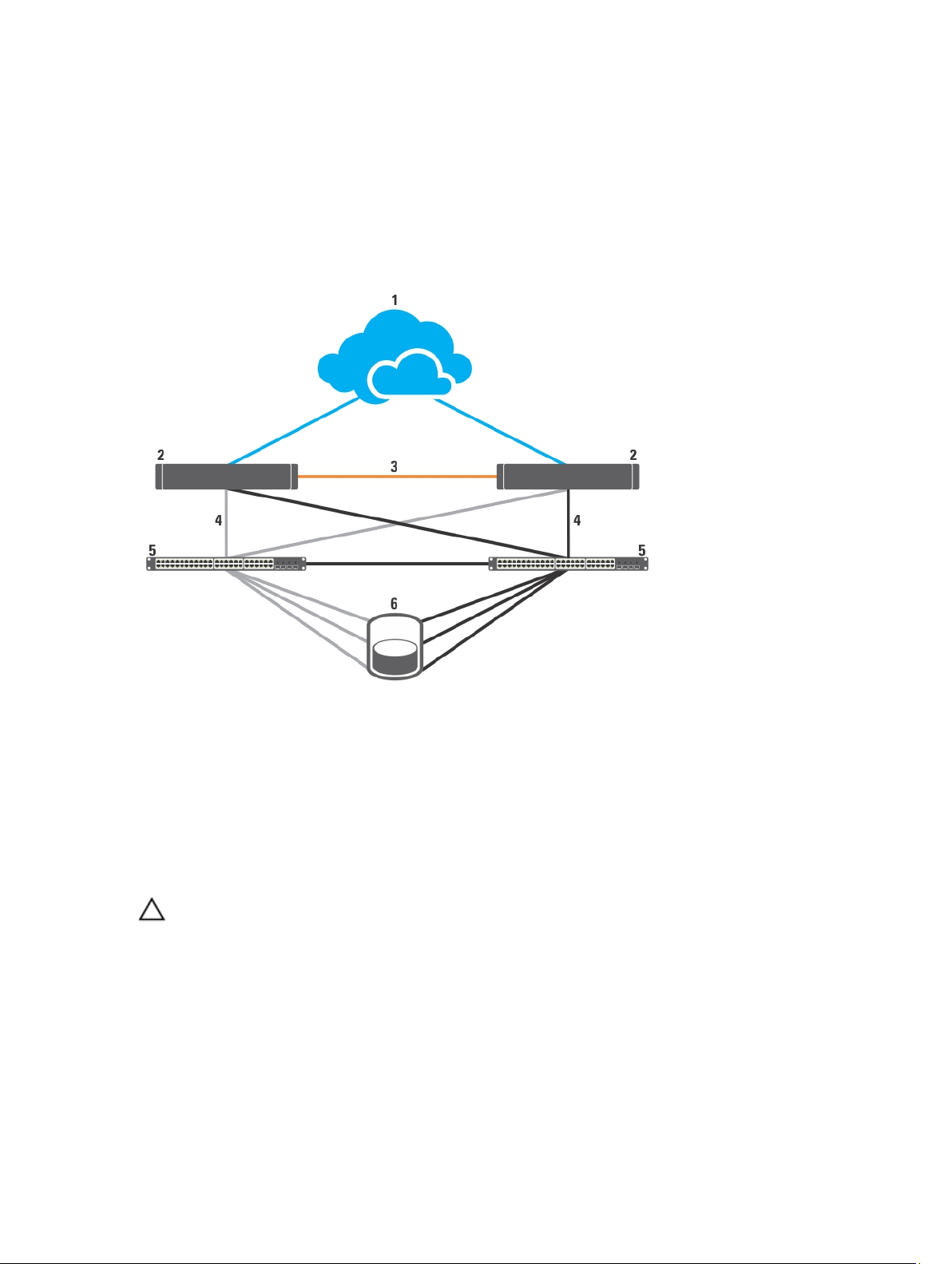
iSCSI SAN-Attached Cluster
In an iSCSI switch-attached cluster, all the nodes are attached to a single storage array or to multiple storage arrays
through redundant iSCSI SANs for high-availability. iSCSI SAN-attached clusters provide superior configuration
flexibility, expandability, and performance.
Figure 1. iSCSI SAN-Attached Cluster
1. public network
2. cluster nodes
3. private network
4. iSCSI connections
5. Gigabit or 10 Gigabit Ethernet switches
6. storage system
Other Documents You May Need
CAUTION: For important safety and regulatory information, see the safety information that is shipped with your
system. Warranty information may be included within this document or as a separate document.
The following documentation is available at support.dell.com/manuals and equallogic.com:
• The
Rack Installation Guide
• The
Getting Started Guide
• The
Dell Failover Clusters with Microsoft Windows Server 2003 Installation and Troubleshooting Guide
more information on deploying your cluster with the Windows Server 2003 operating system.
• The
Dell Failover Clusters with Microsoft Windows Server 2008 Installation and Troubleshooting Guide
more information on deploying your cluster with the Windows Server 2008 operating system.
included with your rack solution describes how to install your system into a rack.
provides an overview of initially setting up your system.
provides
provides
9

• The
Dell Cluster Configuration Support Matrices
components, and driver or firmware versions for your Failover Cluster.
• Operating system documentation describes how to install (if necessary), configure, and use the operating
system software.
• Documentation for any hardware and software components you purchased separately provides information to
configure and install those options.
• The Dell PowerVault tape library documentation provides information for installing, troubleshooting, and
upgrading the tape library.
• Dell EqualLogic documentation:
– Release Notes — Provides the latest information about the Dell EqualLogic PS Series arrays and/or Host
Integration Tools.
– QuickStart — Describes how to set up the array hardware and create a Dell EqualLogic PS Series
group.
– Group Administration — Describes how to use the Group Manager graphical user interface (GUI) to
manage a Dell EqualLogic PS Series group.
– CLI Reference — Describes how to use the Group Manager command line interface (CLI) to manage a
Dell EqualLogic PS Series group and individual arrays.
– Hardware Maintenance — Provides information about maintaining the array hardware.
– Host Integration Tools Installation and User Guide — Provides information on creating and expanding
the Dell EqualLogic PS Series groups, configuring multipath I/O, performing manual transfer replication,
and backing up and restoring data.
–
Host Integration Tools EqualLogic Auto-Snapshot Manager/Microsoft Edition User Guide
information for creating and managing copies of storage objects (such as volumes or databases)
located on the Dell EqualLogic PS series groups.
– SAN HeadQuarters User Guide — Provides centralized monitoring, historical performance trending, and
event reporting for multiple PS series groups.
– Online Help — In the Group Manager GUI, expand Tools in the far left panel and then click Online Help
for help on both the GUI and the CLI.
• Release notes or readme files may be included to provide last-minute updates to the system or documentation,
or advanced technical reference material intended for experienced users or technicians.
provides a list of supported operating systems, hardware
— Provides
10
2
Cluster Hardware Cabling
This section provides information on cluster hardware cabling.
Mouse, Keyboard, And Monitor Cabling Information
When installing a cluster configuration in a rack, you must include a switch box to connect the mouse, keyboard, and
monitor to the nodes. For instructions on cabling the connections of each node to the switch box, see the documentation
included with your rack.
Power Supplies Cabling Information
See the documentation for each component in your cluster solution to ensure that the specific power requirements are
satisfied.
The following guidelines are recommended to protect your cluster solution from power-related failures:
• For cluster nodes and storage arrays with multiple power supplies, plug each power supply into a separate AC
circuit.
• Use uninterruptible power supplies (UPS).
• For some environments, consider having backup generators and power from separate electrical substations.
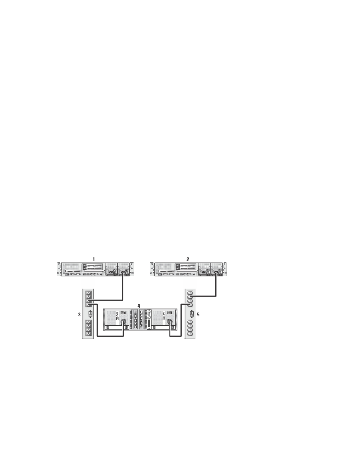
The following figures illustrate recommended methods for power cabling a cluster solution consisting of two Dell
PowerEdge systems and one storage array. To ensure redundancy, the primary power supplies of all the components
are grouped into one or two circuits and the redundant power supplies are grouped into a different circuit.
Figure 2. Power Cabling Example With One Power Supply in PowerEdge Systems
1. cluster node 1
2. cluster node 2
3. primary power supplies on one AC power strip
4. EqualLogic PS series storage array
11
5. redundant power supplies on one AC power strip
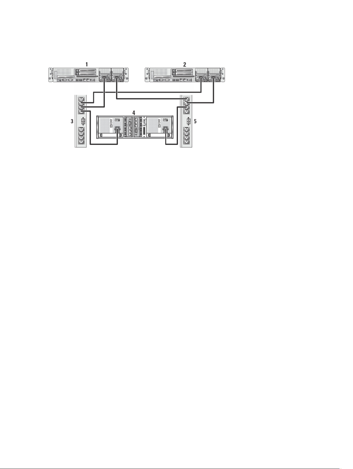
Figure 3. Power Cabling Example With Two Power Supplies in the PowerEdge Systems
1. cluster node 1
2. cluster node 2
3. primary power supplies on one AC power strip
4. EqualLogic PS series storage array
5. redundant power supplies on one AC power strip
Cluster Cabling Information For Public And Private Networks
The network adapters in the cluster nodes provide at least two network connections for each node.
The following section describes the network connections.
Network Connection Description
Public network
Private network A dedicated connection for sharing cluster health and status information only.
The following figure shows an example of cabling in which dedicated network adapters in each node are connected to
each other (for the private network) and the remaining network adapters are connected to the public network.
– All connections to the client LAN.
– At least one public network must be configured for both client access and cluster
communications.
12
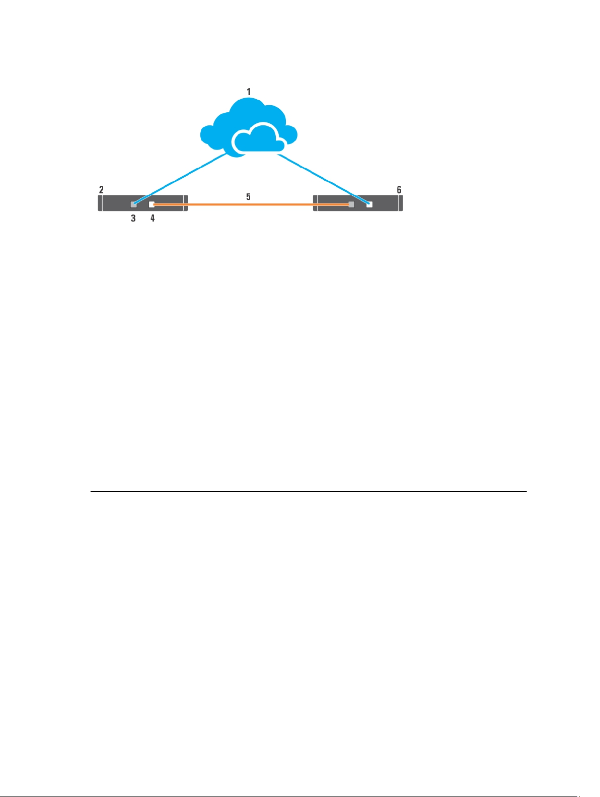
Figure 4. Example of Network Cabling Connection
1. public network
2. cluster node 1
3. public network adapter
4. private network adapter
5. private network
6. cluster node 2
For Public Network
Any network adapter supported by a system running TCP/IP may be used to connect to the public network segments.
You can install additional network adapters to support additional public network segments or to provide redundancy in
the event of a faulty primary network adapter or switch port.
For Private Network
The private network connection to the nodes is provided by a different network adapter in each node. This network is
used for intra-cluster communications. The following table describes the two possible private network configurations.
Method Hardware Components Connection
Network switch Gigabit or 10 Gigabit Ethernet
network adapters and switches
Depending on the hardware, connect the CAT5e
CAT6, CAT6a, or CAT7 cables, the multi-mode
optical cables with Local Connectors (LCs), or the
twinax cables from the network adapters in the
nodes to a switch.
Point-to-Point (two-node
clusters only)
Copper Gigabit network adapters
with RJ-45 connectors
Copper 10 Gigabit Ethernet network
adapters with RJ-45 connectors
Copper 10 Gigabit Ethernet network
adapters with SFP+ connectors
Connect a CAT5e or better (CAT6, CAT6a, or CAT7)
Ethernet cable between the network adapters in
both nodes.
Connect a CAT6 or better (CAT6a or CAT7) Ethernet
cable between the network adapters in the nodes.
Connect a twinax cable between the network
adapters in both nodes.
13

Method Hardware Components Connection
Optical Gigabit or 10 Gigabit Ethernet
network adapters with LC
connectors
Connect a multi-mode optical cable between the
network adapters in both nodes.
Dual-Port Network Adapters Usage
You can configure your cluster to use the public network as a failover for private network communications. If dual-port
network adapters are used, do not use both ports simultaneously to support both the public and private networks.
NIC Teaming
NIC teaming combines two or more NICs to provide load balancing and fault tolerance. Your cluster supports NIC
teaming, but only for the public network; NIC teaming is not supported for the private network or an iSCSI network.
NOTE: Use the same brand of NICs in a team, and do not mix brands of teaming drivers.
Storage Array(s) Cabling Information
This section provides information for connecting your cluster to one or more storage arrays.
Connect the cables between the iSCSI switches and configure the iSCSI switches. For more information see, Network
Configuration Recommendations.
Connect the iSCSI ports from the servers and array(s) to the Gigabit switches, using proper network cables.
For Gigabit iSCSI ports with RJ-45 connectors: use CAT5e or better (CAT6, CAT6a, or CAT7)
For 10 Gigabit iSCSI ports:
• With RJ-45 connectors: use CAT6 or better (CAT6a or CAT7)
• With LC connectors: use fiber optic cable acceptable for 10GBASE-SR
• With SFP+ connectors: use twinax cable
Cabling The Storage For Your iSCSI SAN-Attached Cluster
An iSCSI SAN-attached cluster is a cluster configuration where all cluster nodes are attached to a single storage array
or to multiple storage arrays using redundant iSCSI switches.
The following figures show examples of a two-node iSCSI SAN-attached cluster and a sixteen-node iSCSI SANattached cluster.
Similar cabling concepts can be applied to clusters that contain a different number of nodes.
NOTE: The connections listed in this section are a representative of one proven method of ensuring redundancy in
the connections between the cluster nodes and the storage array(s). Other methods that achieve the same type of
redundant connectivity may be acceptable.
14
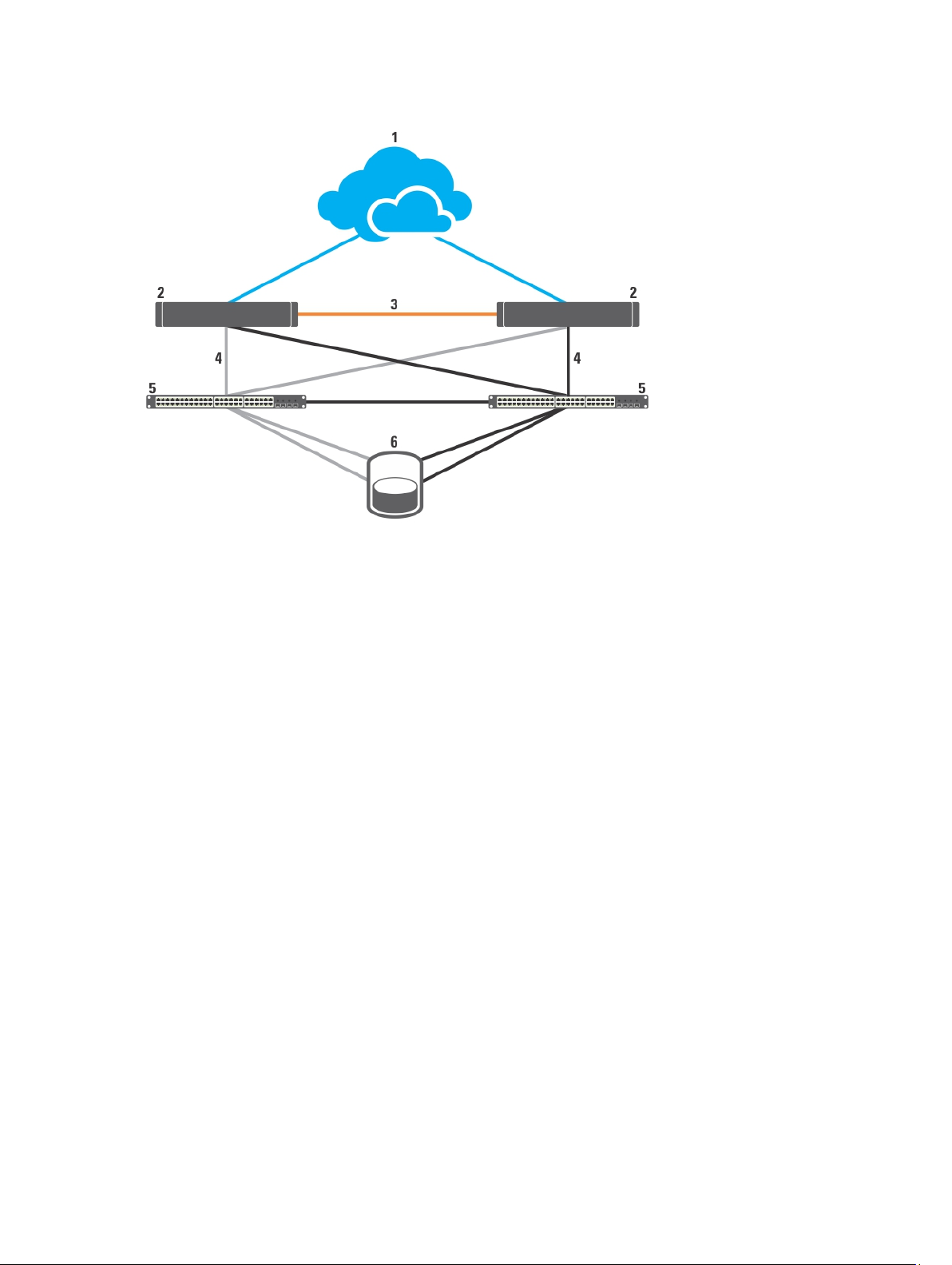
Figure 5. Two-Node iSCSI SAN-Attached Cluster
1. public network
2. cluster node
5. Gigabit or 10 Gigabit Ethernet switches
6. storage system
3. private network
4. iSCSI connections
Gigabit NICs can access the 10 Gigabit iSCSI ports on the EqualLogic PS4110/PS6010/PS6110/PS6510 storage systems if
any one of the following conditions exist:
• The switch supports both Gigabit and 10 Gigabit Ethernet.
• The servers connected to a Gigabit Ethernet switch are cascaded to the 10 Gigabit Ethernet that is attached to
the storage system.
15
 Loading...