

Page 1

Dell™ PowerEdge™ 6950 Systems
Hardware Owner’s Manual
www.dell.com | support.dell.com
Page 2
Notes, Notices, and Cautions
NOTE: A NOTE indicates important information that helps you make better use of your computer.
NOTICE: A NOTICE indicates either potential damage to hardware or loss of data and tells you how to avoid the
problem.
CAUTION: A CAUTION indicates a potential for property damage, personal injury, or death.
____________________
Information in this document is subject to change without notice.
© 2006 Dell Inc. All rights reserved.
Reproduction in any manner whatsoever without the written permission of Dell Inc. is strictly forbidden.
Trademarks used in this text: Dell, the DELL logo, Inspiron, Dell Precision, Dimension, OptiPlex, Latitude, PowerEdge, P owerV ault, P owerApp,
Dell OpenManage, and Dell XPS are trademarks of Dell Inc.; Intel, Pentium, Xeon, and Celeron are re gistered trademarks of Intel Corporation;
Microsoft and Windows are registered trademarks of Microsoft Corporation.
Other trademarks and trade names may be used in this document to refer to either the entities claiming the marks and names or their products.
Dell Inc. disclaims any proprietary interest in trademarks and trade names other than its own.
Model EMU01
September 2006 P/N PM296 A00
Page 3

Contents
1 About Your System. . . . . . . . . . . . . . . . . . . . . . . . . . . . . 9
Other Information You May Need . . . . . . . . . . . . . . . . . . . . . . . . . 9
Accessing System Features During Startup
Front-Panel Features and Indicators
Hard-Drive Indicator Codes
. . . . . . . . . . . . . . . . . . . . . . . . . 13
Back-Panel Features and Indicators
Connecting External Devices
Power Indicator Codes
NIC Indicator Codes
. . . . . . . . . . . . . . . . . . . . . . . . . . . . . . . 16
LCD Status Messages
. . . . . . . . . . . . . . . . . . . . . . . . . . . . . . 15
. . . . . . . . . . . . . . . . . . . . . . . . . . . . . . 16
. . . . . . . . . . . . . . . . . . . . . . . . 14
Solving Problems Described by LCD Status Messages
Removing LCD Status Messages
System Messages
Warning Messages
Diagnostics Messages
Alert Messages
. . . . . . . . . . . . . . . . . . . . . . . . . . . . . . . . 24
. . . . . . . . . . . . . . . . . . . . . . . . . . . . . . . 30
. . . . . . . . . . . . . . . . . . . . . . . . . . . . . . 30
. . . . . . . . . . . . . . . . . . . . . . . . . . . . . . . . . 30
. . . . . . . . . . . . . . . . . . . 10
. . . . . . . . . . . . . . . . . . . . . . 11
. . . . . . . . . . . . . . . . . . . . . . 14
. . . . . . . . . . 23
. . . . . . . . . . . . . . . . . . . . . . 24
2 Using the System Setup Program . . . . . . . . . . . . . . . . . . 31
Entering the System Setup Program . . . . . . . . . . . . . . . . . . . . . . . 31
Responding to Error Messages
Using the System Setup Program
. . . . . . . . . . . . . . . . . . . . . . . 31
. . . . . . . . . . . . . . . . . . . . . . 31
System Setup Options
Main Screen
. . . . . . . . . . . . . . . . . . . . . . . . . . . . . . . . 32
Memory Information Screen
CPU Information Screen
Integrated Devices Screen
System Security Screen
Exit Screen
. . . . . . . . . . . . . . . . . . . . . . . . . . . . . . . . . 38
. . . . . . . . . . . . . . . . . . . . . . . . . . . . . . 32
. . . . . . . . . . . . . . . . . . . . . . . . 35
. . . . . . . . . . . . . . . . . . . . . . . . . . 35
. . . . . . . . . . . . . . . . . . . . . . . . . 36
. . . . . . . . . . . . . . . . . . . . . . . . . . 37
Contents 3
Page 4

System and Setup Password Features. . . . . . . . . . . . . . . . . . . . . . 38
Using the System Password
Using the Setup Password
. . . . . . . . . . . . . . . . . . . . . . . . 38
. . . . . . . . . . . . . . . . . . . . . . . . . 40
Disabling a Forgotten Password
Baseboard Management Controller Configuration
Entering the BMC Setup Module
BMC Setup Module Options
. . . . . . . . . . . . . . . . . . . . . . . . . 41
. . . . . . . . . . . . . . . 41
. . . . . . . . . . . . . . . . . . . . . . 42
. . . . . . . . . . . . . . . . . . . . . . . . 42
3 Installing System Components . . . . . . . . . . . . . . . . . . . . 43
Recommended Tools . . . . . . . . . . . . . . . . . . . . . . . . . . . . . . . 44
Inside the System
Removing and Replacing the Optional Front Bezel
Opening and Closing the System
Opening the System
Closing the System
Cooling Fans
Removing a Cooling Fan
Replacing a Cooling Fan
Cooling Shrouds
Removing the Cooling Shrouds
Replacing the Cooling Shrouds
. . . . . . . . . . . . . . . . . . . . . . . . . . . . . . . . 44
. . . . . . . . . . . . . . . 45
. . . . . . . . . . . . . . . . . . . . . . . . 46
. . . . . . . . . . . . . . . . . . . . . . . . . . . . . 46
. . . . . . . . . . . . . . . . . . . . . . . . . . . . . 47
. . . . . . . . . . . . . . . . . . . . . . . . . . . . . . . . . . . 48
. . . . . . . . . . . . . . . . . . . . . . . . . . 48
. . . . . . . . . . . . . . . . . . . . . . . . . . 49
. . . . . . . . . . . . . . . . . . . . . . . . . . . . . . . . . 49
. . . . . . . . . . . . . . . . . . . . . . . 49
. . . . . . . . . . . . . . . . . . . . . . . 50
4 Contents
Power Supplies
Removing a Power Supply
Replacing a Power Supply
Expansion Cards
. . . . . . . . . . . . . . . . . . . . . . . . . . . . . . . . . 51
. . . . . . . . . . . . . . . . . . . . . . . . . 51
. . . . . . . . . . . . . . . . . . . . . . . . . 52
. . . . . . . . . . . . . . . . . . . . . . . . . . . . . . . . . 52
Expansion Card Installation Guidelines
Installing an Expansion Card
Removing an Expansion Card
RAC Card
System Memory
. . . . . . . . . . . . . . . . . . . . . . . . . . . . . . . . . . . . . 56
. . . . . . . . . . . . . . . . . . . . . . . . . . . . . . . . . 57
. . . . . . . . . . . . . . . . . . . . . . . . 53
. . . . . . . . . . . . . . . . . . . . . . . . 55
General Memory Module Installation Guidelines
Installing Memory Modules
Removing Memory Modules
. . . . . . . . . . . . . . . . . . . . . . . . . 60
. . . . . . . . . . . . . . . . . . . . . . . . 61
. . . . . . . . . . . . . . . . . . . 52
. . . . . . . . . . . . . 58
Page 5

Processors . . . . . . . . . . . . . . . . . . . . . . . . . . . . . . . . . . . . 62
Removing a Processor
Installing a Processor
. . . . . . . . . . . . . . . . . . . . . . . . . . . 62
. . . . . . . . . . . . . . . . . . . . . . . . . . . . 64
Processor VRMs
Installing a VRM
Removing a VRM
Installing a Diskette Drive
Installing an Optical Drive
Hard Drives
Before You Begin
Configuring the Boot Device
Removing a Drive Blank
Installing a Drive Blank
Removing a Hot-Plug Hard Drive
Installing a Hot-Plug Hard Drive
Replacing a Hard Drive in a Hard-Drive Carrier
SAS Controller Cards
Removing a SAS Controller Card
Installing a SAS Controller Card
. . . . . . . . . . . . . . . . . . . . . . . . . . . . . . . . . 66
. . . . . . . . . . . . . . . . . . . . . . . . . . . . . . 66
. . . . . . . . . . . . . . . . . . . . . . . . . . . . . . 67
. . . . . . . . . . . . . . . . . . . . . . . . . . . . 68
. . . . . . . . . . . . . . . . . . . . . . . . . . . . 70
. . . . . . . . . . . . . . . . . . . . . . . . . . . . . . . . . . . . 72
. . . . . . . . . . . . . . . . . . . . . . . . . . . . . . 72
. . . . . . . . . . . . . . . . . . . . . . . . 72
. . . . . . . . . . . . . . . . . . . . . . . . . . 73
. . . . . . . . . . . . . . . . . . . . . . . . . . . 73
. . . . . . . . . . . . . . . . . . . . . . 73
. . . . . . . . . . . . . . . . . . . . . . 74
. . . . . . . . . . . . . . 75
. . . . . . . . . . . . . . . . . . . . . . . . . . . . . . 76
. . . . . . . . . . . . . . . . . . . . . . 76
. . . . . . . . . . . . . . . . . . . . . . 76
Installing the SAS RAID Controller Card Battery
Connecting an External SAS Tape Drive
. . . . . . . . . . . . . . . . . . . . 77
Connecting an External Fibre Channel Storage Device
. . . . . . . . . . . . . . 76
. . . . . . . . . . . . . 78
System Battery
Replacing the System Battery
. . . . . . . . . . . . . . . . . . . . . . . . . . . . . . . . . . 78
. . . . . . . . . . . . . . . . . . . . . . . 78
Control Panel Assembly (Service-Only Procedure)
Removing the Control Panel
Installing the Control Panel
Fan Interposer Board (Service-Only Procedure)
Removing a Fan Interposer Board
Installing a Fan Interposer Board
. . . . . . . . . . . . . . . . . . . . . . . . 80
. . . . . . . . . . . . . . . . . . . . . . . . . 81
. . . . . . . . . . . . . . . . 82
. . . . . . . . . . . . . . . . . . . . . 82
. . . . . . . . . . . . . . . . . . . . . . 83
Power Distribution Board (Service-Only Procedure)
Removing the Power Distribution Board
Installing the Power Distribution Board
. . . . . . . . . . . . . . . . . . 84
. . . . . . . . . . . . . . . . . . 85
. . . . . . . . . . . . . . . 80
. . . . . . . . . . . . . . 84
Contents 5
Page 6

Chassis Intrusion Switch (Service-Only Procedure) . . . . . . . . . . . . . . 86
Removing the Chassis Intrusion Switch
Installing the Chassis Intrusion Switch
. . . . . . . . . . . . . . . . . . 86
. . . . . . . . . . . . . . . . . . . 87
SAS Backplane (Service-Only Procedure)
Removing the SAS Backplane
Installing the SAS Backplane
System Board (Service-Only Procedure)
Removing the System Board
Installing the System Board
. . . . . . . . . . . . . . . . . . . . . . . . 89
. . . . . . . . . . . . . . . . . . . . . . . . . 93
. . . . . . . . . . . . . . . . . . . 87
. . . . . . . . . . . . . . . . . . . . . . . 87
. . . . . . . . . . . . . . . . . . . . . . . . 89
. . . . . . . . . . . . . . . . . . . . 89
4 Troubleshooting Your System . . . . . . . . . . . . . . . . . . . . . 97
Safety First—For You and Your System . . . . . . . . . . . . . . . . . . . . . 97
Start-Up Routine
Checking Basic Power Problems
Checking the Equipment
Troubleshooting IRQ Assignment Conflicts
Troubleshooting External Connections
Troubleshooting the Video Subsystem
Troubleshooting the Keyboard
Troubleshooting the Mouse
Troubleshooting Serial I/O Problems
Troubleshooting a Serial I/O Device
Troubleshooting a USB Device
. . . . . . . . . . . . . . . . . . . . . . . . . . . . . . . . . 97
. . . . . . . . . . . . . . . . . . . . . . . . 98
. . . . . . . . . . . . . . . . . . . . . . . . . . . . . 98
. . . . . . . . . . . . . . . . . 98
. . . . . . . . . . . . . . . . . . . 99
. . . . . . . . . . . . . . . . . . . 99
. . . . . . . . . . . . . . . . . . . . . . 100
. . . . . . . . . . . . . . . . . . . . . . . . 100
. . . . . . . . . . . . . . . . . . . . . 101
. . . . . . . . . . . . . . . . . . . 101
. . . . . . . . . . . . . . . . . . . . . . 101
6 Contents
Troubleshooting a NIC
Troubleshooting a Wet System
Troubleshooting a Damaged System
Troubleshooting the System Battery
Troubleshooting Power Supplies
. . . . . . . . . . . . . . . . . . . . . . . . . . . . . 102
. . . . . . . . . . . . . . . . . . . . . . . . . 103
. . . . . . . . . . . . . . . . . . . . . . 103
. . . . . . . . . . . . . . . . . . . . . . 104
. . . . . . . . . . . . . . . . . . . . . . . 105
Troubleshooting System Cooling Problems
Troubleshooting a Fan
Troubleshooting System Memory
Troubleshooting a Diskette Drive
. . . . . . . . . . . . . . . . . . . . . . . . . . 106
. . . . . . . . . . . . . . . . . . . . . . . 106
. . . . . . . . . . . . . . . . . . . . . . . 108
. . . . . . . . . . . . . . . . . . 105
Page 7

Troubleshooting an Optical Drive . . . . . . . . . . . . . . . . . . . . . . . 109
Troubleshooting a Hard Drive
Troubleshooting a SAS Controller or SAS RAID Controller
Troubleshooting an External SAS Tape Drive
Troubleshooting Expansion Cards
Troubleshooting the Microprocessors
. . . . . . . . . . . . . . . . . . . . . . . . . 110
. . . . . . . . . . 111
. . . . . . . . . . . . . . . . . 112
. . . . . . . . . . . . . . . . . . . . . . . 113
. . . . . . . . . . . . . . . . . . . . 114
5 Running the System Diagnostics . . . . . . . . . . . . . . . . . . 117
Using Dell PowerEdge Diagnostics . . . . . . . . . . . . . . . . . . . . . . 117
System Diagnostics Features
When to Use the System Diagnostics
Running the System Diagnostics
System Diagnostics Testing Options
Using the Custom Test Options
Selecting Devices for Testing
Selecting Diagnostics Options
Viewing Information and Results
. . . . . . . . . . . . . . . . . . . . . . . . . 117
. . . . . . . . . . . . . . . . . . . . . 118
. . . . . . . . . . . . . . . . . . . . . . . 118
. . . . . . . . . . . . . . . . . . . . . . 118
. . . . . . . . . . . . . . . . . . . . . . . . 118
. . . . . . . . . . . . . . . . . . . . . . . 119
. . . . . . . . . . . . . . . . . . . . . . 119
. . . . . . . . . . . . . . . . . . . . . 119
6 Jumpers and Connectors . . . . . . . . . . . . . . . . . . . . . . . 121
System Board Jumpers. . . . . . . . . . . . . . . . . . . . . . . . . . . . . 121
Disabling a Forgotten Password
System Board Connectors
SAS Backplane Board Connectors
. . . . . . . . . . . . . . . . . . . . . . . . 123
. . . . . . . . . . . . . . . . . . . . . . . . . . . 124
. . . . . . . . . . . . . . . . . . . . . . 127
7 Getting Help . . . . . . . . . . . . . . . . . . . . . . . . . . . . . . . . 129
Technical Assistance . . . . . . . . . . . . . . . . . . . . . . . . . . . . . 129
Online Services
AutoTech Service
. . . . . . . . . . . . . . . . . . . . . . . . . . . . . . 129
. . . . . . . . . . . . . . . . . . . . . . . . . . . . . 130
Contents 7
Page 8

Automated Order-Status Service. . . . . . . . . . . . . . . . . . . . . 130
Technical Support Service
. . . . . . . . . . . . . . . . . . . . . . . . 130
Dell Enterprise Training and Certification
Problems With Your Order
Product Information
. . . . . . . . . . . . . . . . . . . . . . . . . . . 131
. . . . . . . . . . . . . . . . . . . . . . . . . . . . . . 131
Returning Items for Warranty Repair or Credit
Before You Call
Contacting Dell
. . . . . . . . . . . . . . . . . . . . . . . . . . . . . . . . . 132
. . . . . . . . . . . . . . . . . . . . . . . . . . . . . . . . . 134
. . . . . . . . . . . . . . . . . . . 131
. . . . . . . . . . . . . . . . 131
Glossary . . . . . . . . . . . . . . . . . . . . . . . . . . . . . . . . . . . . . 155
Index . . . . . . . . . . . . . . . . . . . . . . . . . . . . . . . . . . . . . . . . 163
8 Contents
Page 9
About Your System
This section describes the physical, firmware, and software interface features that provide and ensure
the essential functioning of your system. The physical connectors on your system’s front and back
panels provide convenient connectivity and system expansion capability. The system firmware,
applications, and operating systems monitor the system and component status and alert you when a
problem arises. System conditions can be reported by any of the following:
• Front or back panel indicators
• LCD status messages
• System messages
• Warning messages
• Diagnostics messages
• Alert messages
This section describes each type of message, lists the possible causes, and provides steps to resolve
any problems indicated by a message. The system indicators and features are illustrated in this
section.
Other Information You May Need
CAUTION: The Product Information Guide provides important safety and regulatory information. Warranty
information may be included within this document or as a separate document.
• The
• The
• CDs included with your system provide documentation and tools for configuring and managing
• Systems management software documentation describes the features, requirements, installation,
• Operating system documentation describes how to install (if necessary), configure, and use the
• Documentation for any components you purchased separately provides information to configure
Rack Installation Guide
describes how to install your system into a rack.
Getting Started Guide
technical specifications.
your system.
and basic operation of the software.
operating system software.
and install these options.
or
Rack Installation Instructions
provides an overview of system features, setting up your system, and
included with your rack solution
About Your System 9
Page 10

• Updates are sometimes included with the system to describe changes to the system, software, and/or
documentation.
NOTE: Always check for updates on support.dell.com and read the updates first because they often
supersede information in other documents.
• Release notes or readme files may be included to provide last-minute updates to the system or
documentation or advanced technical reference material intended for experienced users or
technicians.
Accessing System Features During Startup
Table 1-1 describes keystrokes that may be entered during startup to access system features. If your
operating system begins to load before you enter the keystroke, allow the system to finish booting, and
then restart your system and try again.
Table 1-1. Keystrokes for Accessing System Features
Keystroke Description
<F2> Enters the System Setup program. See "Using the System Setup Program" on page 31.
<F10> Enters the System Diagnostics program. See "Running the System Diagnostics" on page 118.
<F11> Enters the boot mode selection screen, allowing you to choose a boot device.
<F12> Exits PXE boot.
<Ctrl+E> Enters the Baseboard Management Controller (BMC) Management Utility, which allows access to
the system event log (SEL). See the BMC User’s Guide for more information on setup and use
of BMC.
<Ctrl+C> Enters the SAS Configuration Utility. See your SAS adapter User’s Guide for more information.
<Ctrl+S> Option is displayed only if you have PXE support enabled through the System Setup Program (see
"Integrated Devices Screen" on page 36). This keystroke allows you to configure NIC settings for
PXE boot. For more information, see the documentation for the integrated NIC.
<Ctrl+D> If you have the optional Dell Remote Access Controller (DRAC) installed, this keystroke allows
access to selected DRAC configuration settings. See the DRAC User’s Guide for more information
on setup and use of DRAC.
10 About Your System
Page 11
Front-Panel Features and Indicators
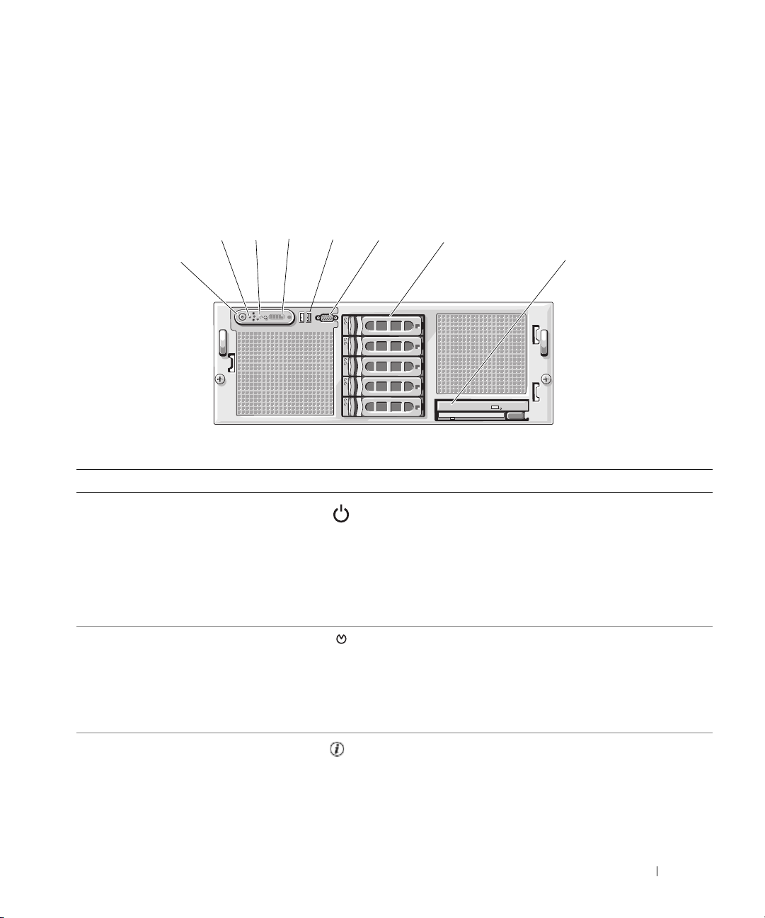
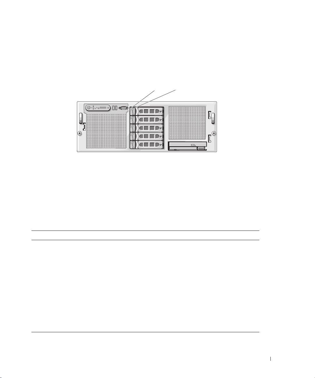
Figure 1-1 shows the controls, indicators, and connectors located behind the optional rack bezel on the
system's front panel.
Figure 1-1. Front-Panel Features and Indicators
4
3
2
1
Table 1-2. Front-Panel LED Indicators, Buttons, and Connectors
Item Indicator, Button, or Connector Icon Description
1 Power-on indicator, power
button
5
6
7
8
The power button controls the DC power supply output
to the system.
NOTE: If you turn off the system using the power button
and the system is running an ACPI-compliant operating
system, the system performs a graceful shutdown before
the power is turned off. If the system is not running an
ACPI-compliant operating system, the power is turned off
immediately after the power button is pressed.
2 NMI button Used to troubleshoot software and device driver errors
when using certain operating systems. This button can
be pressed using the end of a paper clip.
Use this button only if directed to do so by qualified
support personnel or by the operating system's
documentation.
3 System identification button The identification buttons on the front and back panels
can be used to locate a particular system within a rack.
When one of these buttons is pushed, the blue system
status indicator on the front and back blinks until one of
the buttons is pushed again.
About Your System 11
Page 12
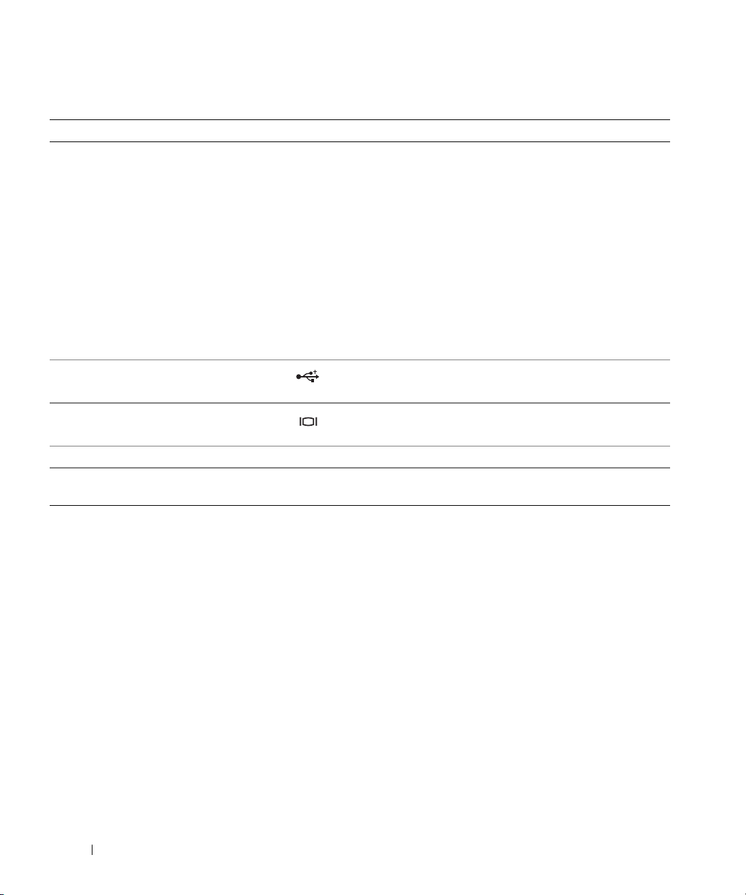
Table 1-2. Front-Panel LED Indicators, Buttons, and Connectors (continued)
Item Indicator, Button, or Connector Icon Description
4 LCD display Provides system ID, status information, and system error
messages.
The LCD display lights during normal system operation.
Both the systems management software and the
identification buttons located on the front and back of
the system can cause the LCD to flash blue to identify a
particular system.
The LCD display lights amber when the system needs
attention due to a problem with power supplies, fans,
system temperature, or hard drives.
NOTE: If the system is connected to AC power and an
error has been detected, the LCD display lights amber
regardless of whether the system has been powered on.
5 USB connectors (2) Connects USB 2.0-compliant devices to the system.
6 Video connector Connects a monitor to the system.
7 Hard drives (optional) Five 3.5" drives.
8 Optical drive and diskette drive
(optional)
Optional slimline optical drive and diskette drive
NOTE: DVD devices are data only.
12 About Your System
Page 13
Hard-Drive Indicator Codes
The hard-drive carriers have two indicators—a drive-activity indicator and a drive-status indicator. See
Figure 1-2.
Figure 1-2. Hard-Drive Indicators
1
1 drive-status indicator (green
and amber)
2
2 green drive-activity indicator
Table 1-3 lists the drive indicator patterns for RAID hard drives. Different patterns are displayed as drive
events occur in the system. For example, if a hard drive fails, the "drive failed" pattern appears. After the
drive is selected for removal, the "drive being prepared for removal" pattern appears, followed by the "drive
ready for insertion or removal" pattern. After the replacement drive is installed, the "drive being prepared for
operation" pattern appears, followed by the "drive online" pattern.
Table 1-3. Hard-Drive Indicator Patterns for RAID
Condition Drive-Status Indicator Pattern
Identify drive/preparing for
removal
Drive ready for insertion or
removal
Drive predicted failure Blinks green, amber, and off.
Drive failed Blinks amber four times per second.
Drive rebuilding Blinks green slowly.
Drive online Steady green.
Rebuild halted Blinks green three seconds, amber three seconds, and off six seconds.
Blinks green two times per second
Off
NOTE: The drive status indicator remains off until all hard drives are
initialized after system power is applied. Drives are not ready for
insertion or removal during this time.
About Your System 13
Page 14
Back-Panel Features and Indicators
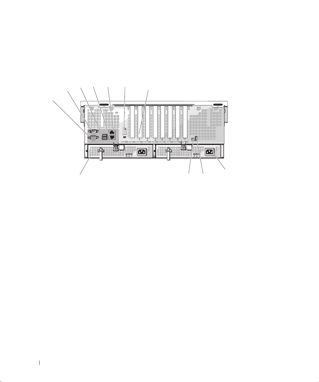
Figure 1-3 shows the controls, indicators, and connectors located on the system's back panel.
Figure 1-3. Back-Panel Features and Indicators
45
3
2
1
11
1 serial connector 2 video connector 3 USB connectors (2)
4 NIC2 connector 5 NIC1 connector 6 remote access controller port
7 expansion-card slots 8 power supply 2 9 system status indicator
10 system identification button 11 power supply 1
6
7
9
10
8
(optional)
Connecting External Devices
When connecting external devices to your system, follow these guidelines:
• Most devices must be connected to a specific connector and device drivers must be installed before the
device operates properly. (Device drivers are normally included with your operating system software or
with the device itself.) See the documentation that accompanied the device for specific installation
and configuration instructions.
• Always attach external devices while your system is turned off. Next, turn on any external devices
before turning on the system (unless the documentation for the device specifies otherwise).
For information about individual connectors, see "Jumpers and Connectors" on page 121. For information
about enabling, disabling, and configuring I/O ports and connectors, see "Using the System Setup Program"
on page 31.
14 About Your System
Page 15
Power Indicator Codes
The power button on the front panel controls the power input to the system's power supplies. The power
indicator can provide information on power status (see
indicator codes.
Table 1-4. Power Button Indicators
Indicator Function
On Indicates that power is supplied to the system and the system is operational.
Off Indicates that no power is supplied to the system.
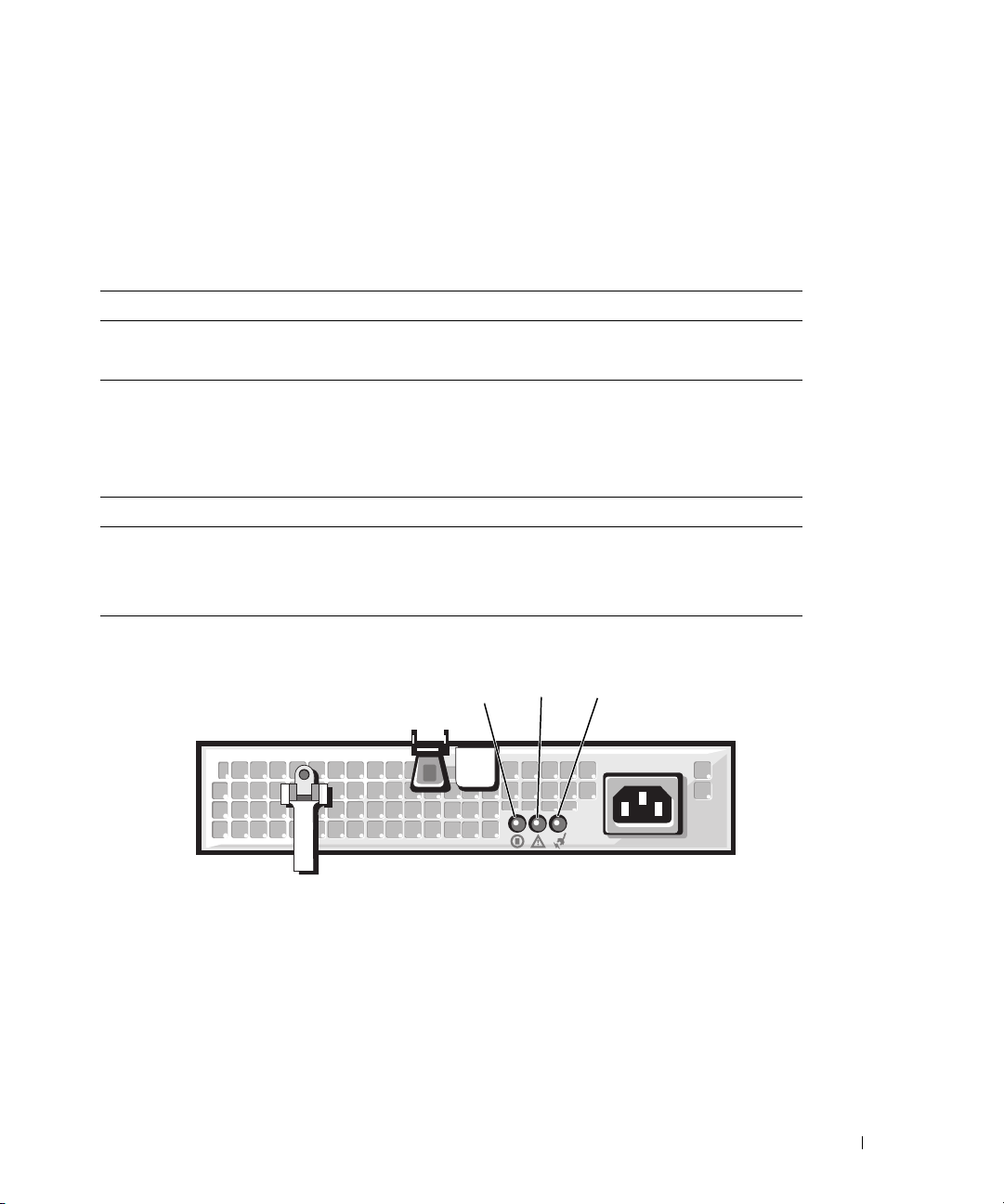
The indicators on the power supplies show whether power is present or whether a power fault has
occurred (see Figure 1-4).
Table 1-5. Power Supply Indicators
Indicator Function
Power supply status Green indicates that the power supply is operational.
Power supply fault Amber indicates a problem with the power supply.
AC line status Green indicates that a valid AC source is connected to the power supply.
Figure 1-4. Power Supply Indicators
Figure 1-1
). Table 1-4 lists the power button
1
1 power supply status indicator 2 power supply fault indicator 3 AC line status indicator
2
3
About Your System 15
Page 16
NIC Indicator Codes
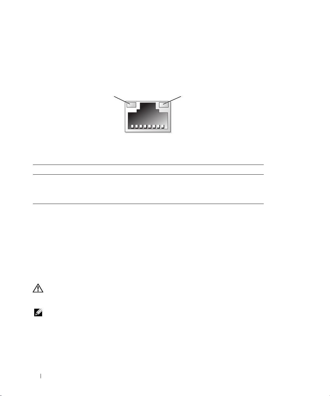
Each NIC on the system back panel has an indicator that provides information on network activity and
link status. See Figure 1-5. Table 1-6 lists the NIC indicator codes.
Figure 1-5. NIC Indicators
1
1 link indicator 2 activity indicator
Table 1-6. NIC Indicator Codes
Indicator Indicator Code
Link and activity indicators are off The NIC is not connected to the network.
Link indicator is green The NIC is connected to a valid link partner on the network.
Activity indicator is blinking amber Network data is being sent or received.
2
LCD Status Messages
The system's control panel LCD provides status messages to signify when the system is operating
correctly or when the system needs attention.
The LCD lights blue to indicate a normal operating condition, and lights amber to indicate an error
condition. The LCD scrolls a message that includes a status code followed by descriptive text. Table 1-7
lists the LCD status messages that can occur and the probable cause for each message. The LCD
messages refer to events recorded in the System Event Log (SEL). For information on the SEL and
configuring system management settings, see the systems management software documentation.
CAUTION: Only trained service technicians are authorized to remove the system cover and access any of the
components inside the system. See your Product Information Guide for complete information about safety
precautions, working inside the computer, and protecting against electrostatic discharge.
NOTE: If your system fails to boot, press the System ID button for at least five seconds until an error code appears
on the LCD. Record the code, then see "Getting Help" on page 129.
16 About Your System
Page 17

Table 1-7. LCD Status Messages
Line 1
Message
N/A
E1000 FAILSAFE, Call
E1A14 SAS Cable A SAS cable A is unseated, missing,
E1A15 SAS Cable B SAS cable B is unseated, missing,
E1114 Temp Ambient Ambient system temperature is
E1210 CMOS Batt CMOS battery is missing, or the
E1211 ROMB Batt RAID battery is either missing,
E12
E1229 CPU # VCORE Processor # VCORE voltage
E122A CPU # VTT Processor # VTT voltage has
Line 2
Message
SYSTEM NAME
Support
nn XX
Causes Corrective Actions
A 62-character string that can be
defined by the user in the System
Setup program.
SYSTEM NAME
The
under the following conditions:
• The system is powered on.
• The power is off and active
POST errors are displayed.
or bad.
or bad.
out of acceptable range.
voltage is out of acceptable range.
bad, or unable to recharge due to
thermal issues.
PwrGd Specified voltage regulator has
failed.
regulator has failed.
exceeded the allowable voltage
range
displays
This message is for information
only.
You can change the system string
in the System Setup program. See
"Using the System Setup
Program" on page 31.
See "Getting Help" on page 129.
Check the cable connection to
the SAS backplane. See "SAS
Backplane Board Connectors" on
page 127.
Check the cable connection to
the SAS backplane. See "SAS
Backplane Board Connectors" on
page 127.
See "Troubleshooting System
Cooling Problems" on page 105.
See "Troubleshooting the System
Battery" on page 104.
Reseat the RAID battery. See
"Installing the SAS RAID
Controller Card Battery" on
page 76, and "Troubleshooting
System Cooling Problems" on
page 105.
See "Getting Help" on page 129.
See "Getting Help" on page 129.
See "Getting Help" on page 129.
About Your System 17
Page 18
Table 1-7. LCD Status Messages (continued)
Line 1
Message
E122B 0.9V Over
E122C CPU Power Fault A voltage regulator failure was
E122D CPU # VDDIO Processor # VDDIO voltage has
E122E CPU # VDDA Processor # VDDA voltage has
E1310 RPM Fan ## RPM of specified cooling fan is
E1313 Fan Redundancy One or more cooling fans has
E1410 CPU # IERR Specified microprocessor is
Line 2
Message
Voltage
Causes Corrective Actions
0.9 V regulator voltage has
exceeded the allowable voltage
range
detected when the processor
regulator(s) was enabled
exceeded the allowable voltage
range
exceeded the allowable voltage
range
out of acceptable operating range.
failed. Cooling fan redundancy
has been lost.
reporting a system error.
See "Getting Help" on page 129.
See "Getting Help" on page 129.
See "Getting Help" on page 129.
See "Getting Help" on page 129.
See "Troubleshooting System
Cooling Problems" on page 105.
See "Troubleshooting System
Cooling Problems" on page 105.
See your system’s Information
Update Tech Sheet located on
support.dell.com for the most
current system information. If the
problem persists, see "Getting
Help" on page 129.
18 About Your System
Page 19
Table 1-7. LCD Status Messages (continued)
Line 1
Message
E1414 CPU # Thermtrip Specified microprocessor is out of
E1418 CPU # Presence Specified processor is missing or
E1423 CPU # VRM
E141C CPU Mismatch Processors are in a configuration
E141F CPU Protocol The system BIOS has reported a
E1420 CPU Bus PERR The system BIOS has reported a
E1421 CPU Init The system BIOS has reported a
Line 2
Message
Missing
Causes Corrective Actions
acceptable temperature range and
has halted operation.
bad, and the system is in an
unsupported configuration.
VRM for specified processor is
missing or faulty.
unsupported by Dell.
processor protocol error.
processor bus parity error.
processor initialization error.
See "Troubleshooting System
Cooling Problems" on page 105.
If the problem persists, ensure
that the microprocessor heat
sinks are properly installed. See
"Troubleshooting the
Microprocessors" on page 114.
NOTE: The LCD continues to
display this message until the
system’s power cord is
disconnected and reconnected to
the AC power source, or the SEL is
cleared using either Server
Assistant or the BMC Management
Utility. See the Dell OpenManage
Baseboard Management
Controller User’s Guide for
information about these utilities.
See "Troubleshooting the
Microprocessors" on page 114.
Remove and reseat the specified
VRM. See "Processor VRMs" on
page 66.
If the problem persists, the
system board is faulty. See
"Getting Help" on page 129.
Ensure that your processors
match and conform to the type
described in the Microprocessor
Technical Specifications outlined
in your system’s Getting Started
Guide.
See "Getting Help" on page 129.
See "Getting Help" on page 129.
See "Getting Help" on page 129.
About Your System 19
Page 20
Table 1-7. LCD Status Messages (continued)
Line 1
Message
E1422 CPU Machine Chk The system BIOS has reported a
E1610 PS # Missing Specified power supply is
E1614 PS # Status Specified power supply is
E1618 PS # Predictive Power supply voltage is out of
E161C PS # Input Lost Power source for specified power
E1620 PS # Input Range Power source for specified power
E1624 PS Redundancy Power supply redundancy has
E1625 PS AC Current Power source is out of acceptable
E1710 I/O Channel Chk The system BIOS has reported an
E1711 PCI PERR B## D##
Line 2
Message
F##
PCI PERR Slot #
Causes Corrective Actions
machine check error.
improperly installed or removed.
improperly installed or faulty.
acceptable range; specified power
supply is improperly installed or
faulty.
supply is unavailable, or out of
acceptable range.
supply is unavailable, or out of
acceptable range.
been lost. If the remaining power
supply fails the system will shut
down.
range.
I/O channel check error.
The system BIOS has reported a
PCI parity error on a component
that resides in PCI configuration
space at bus ##, device ##,
function ##.
The system BIOS has reported a
PCI parity error on a component
that resides in PCI slot #.
See "Getting Help" on page 129.
See "Troubleshooting Power
Supplies" on page 105.
See "Troubleshooting Power
Supplies" on page 105.
See "Troubleshooting Power
Supplies" on page 105.
Check the AC power source for
the specified power supply. If
problem persists, see
"Troubleshooting Power Supplies"
on page 105.
Check the AC power source for
the specified power supply. If
problem persists, see
"Troubleshooting Power Supplies"
on page 105.
See "Troubleshooting Power
Supplies" on page 105.
Check the AC power source.
See "Getting Help" on page 129.
Remove and reseat the PCI
expansion cards. If the problem
persists, see "Troubleshooting
Expansion Cards" on page 113.
If the problem persists, the
system board is faulty. See
"Getting Help" on page 129.
20 About Your System
Page 21
Table 1-7. LCD Status Messages (continued)
Line 1
Message
E1712 PCI SERR B## D##
E1714 Unknown Err The system BIOS has determined
E171F PCIE Fatal Err
E1810 HDD ## Fault Specified hard drive has a fault. See "Troubleshooting a Hard
E1811 HDD ## Rbld Abrt Specified hard drive has ended
E1812 HDD ## Removed Specified hard drive has been
E1914 DRAC5 Conn2 Cbl DRAC 5 cable is missing or Reconnect the cable. See "RAC
E2010 No Memory No memory is installed in the
E2011 Mem Config Err Memory detected, but is not
E2012 Unusable Memory Memory is configured, but not
Line 2
Message
F##
PCI SERR Slot #
B## D## F##
PCIE Fatal Err
Slot #
Causes Corrective Actions
The system BIOS has reported a
PCI system error on a component
that resides in PCI configuration
space at buss ##, device ##,
function ##.
The system BIOS has reported a
PCI system error on a component
that resides in slot #.
that there has been an error in the
system, but is unable to
determine its origin.
The system BIOS has reported a
PCIe fatal error on a component
that resides in PCI configuration
space at bus ##, device ##,
function ##.
The system BIOS has reported a
PCIe fatal error on a component
that resides in slot #.
rebuild before completion.
removed from the system.
system.
configurable. Error detected
during memory configuration.
usable. Memory subsystem
failure.
Remove and reseat the PCI
expansion cards. If the problem
persists, see "Troubleshooting
Expansion Cards" on page 113.
If the problem persists, the
system board is faulty. See
"Getting Help" on page 129.
See "Getting Help" on page 129.
Remove and reseat the PCI
expansion cards. If the problem
persists, see "Troubleshooting
Expansion Cards" on page 113.
If the problem persists, the
system board is faulty. See
"Getting Help" on page 129.
Drive" on page 110.
See "Troubleshooting a Hard
Drive" on page 110.
Information only.
Card" on page 56.
Install memory modules. See
"System Memory" on page 57.
See "Troubleshooting System
Memory" on page 106.
See "Troubleshooting System
Memory" on page 106.
About Your System 21
Page 22
Table 1-7. LCD Status Messages (continued)
Line 1
Message
E2013 Shadow BIOS Fail The system BIOS failed to copy
E2014 CMOS Fail CMOS failure. CMOS RAM not
E2015 DMA Controller DMA controller failure. See "Getting Help" on page 129.
E2016 Int Controller Interrupt controller failure. See "Getting Help" on page 129.
E2017 Timer Fail Timer refresh failure. See "Getting Help" on page 129.
E2018 Prog Timer Programmable interval timer
E2019 Parity Error Parity error. See "Getting Help" on page 129.
E201A SIO Err SIO failure. See "Getting Help" on page 129.
E201B Kybd Controller Keyboard controller failure. See "Getting Help" on page 129.
E201C SMI Init System management interrupt
E201D Shutdown Test BIOS shutdown test failure. See "Getting Help" on page 129.
E201E POST Mem Test BIOS POST memory test failure. See "Troubleshooting System
E201F DRAC Config Dell remote access controller
E2020 CPU Config CPU configuration failure. Check screen for specific error
E2021 Memory
E2022 POST Fail General failure after video. Check screen for specific error
Line 2
Message
Population
Causes Corrective Actions
See "Troubleshooting System
its flash image into memory.
functioning properly.
error.
(SMI) initialization failure.
(DRAC) configuration failure.
Incorrect memory configuration.
Memory population order
incorrect.
Memory" on page 106.
See "Getting Help" on page 129.
See "Getting Help" on page 129.
See "Getting Help" on page 129.
Memory" on page 106. If problem
persists, see "Getting Help" on
page 129.
Check screen for specific error
messages.
Ensure that the DRAC card and
cables are properly seated. See
"RAC Card" on page 56. If
problem persists, see your DRAC
documentation.
messages.
Check screen for specific error
messages. See "Troubleshooting
System Memory" on page 106.
messages.
22 About Your System
Page 23

Table 1-7. LCD Status Messages (continued)
Line 1
Message
E2110 MBE DIMM ## & ## One of the DIMMs in the set
E2111 SBE Log Disable
I1910 Intrusion System cover has been removed. Information only.
I1911 >3 ERRs Chk Log LCD overflow message.
I1912 SEL Full System Event Log is full of
W1228 ROMB Batt < 24hr Warns predictively that the RAID
Line 2
Message
DIMM ##
Causes Corrective Actions
See "Troubleshooting System
implicated by "## & ##" has
had a memory multi-bit error
(MBE).
The system BIOS has disabled
memory single-bit error (SBE)
logging, and will not resume
logging further SBEs until the
system is rebooted. "##"
represents the DIMM implicated
by the BIOS.
A maximum of three error
messages can display sequentially
on the LCD. The fourth message
displays as the standard overflow
message.
events, and is unable to log any
more events.
battery has less than 24 hours of
charge left.
Memory" on page 106.
See "Troubleshooting System
Memory" on page 106.
Check the SEL for details on the
events.
Clear the log by deleting event
entries.
Replace RAID battery. See
"Installing the SAS RAID
Controller Card Battery" on
page 76.
NOTE: For the full name of an abbreviation or acronym used in this table, see the "Glossary" on page 155.
Solving Problems Described by LCD Status Messages
The code and text on the LCD can often specify a very precise fault condition that is easily corrected. For
example, if the code E0708 PROC_1_Presence appears, you know that a microprocessor is not
installed in socket 1.
In contrast, you might be able to determine the problem if multiple related errors occur. For example, if
you receive a series of messages indicating multiple voltage faults, you might determine that the problem
is a failing power supply.
About Your System 23
Page 24
Removing LCD Status Messages
For faults associated with sensors, such as temperature, voltage, fans, and so on, the LCD message is
automatically removed when that sensor returns to a normal state. For example, if temperature for a
component goes out of range, the LCD displays the fault; when the temperature returns to the
acceptable range, the message is removed from the LCD. For other faults, you must take action to
remove the message from the display:
• Clear the SEL — You can perform this task remotely, but you will lose the event history for the
system.
• Power cycle — Turn off the system and disconnect it from the electrical outlet; wait approximately
ten seconds, reconnect the power cable, and restart the system.
Any of these actions will remove fault messages, and return the status indicators and LCD colors to the
normal state. Messages will reappear under the following conditions:
• The sensor returns to a normal state but fails again, resulting in a new SEL entry.
• The system is reset and new error events are detected.
• A failure is recorded from another source that maps to the same display entry.
System Messages
System messages appear on the screen to notify you of a possible problem with the system. Table 1-8 lists
the system messages that can occur and the probable cause and corrective action for each message.
NOTE: If you receive a system message that is not listed in Table 1-8, check the documentation for the application
that is running when the message appears or the operating system's documentation for an explanation of the
message and recommended action.
CAUTION: Only trained service technicians are authorized to remove the system cover and access any of the
components inside the system. See your Product Information Guide for complete information about safety
precautions, working inside the computer, and protecting against electrostatic discharge.
Table 1-8. System Messages
Message Causes Corrective Actions
Alert! Node Interleaving
disabled! Memory
configuration does not
support Node Interleaving.
The memory configuration does not
support node interleaving. The
system will run but with reduced
functionality.
Ensure that the memory modules are
installed in a configuration that supports
node interleaving. See "General Memory
Module Installation Guidelines" on
page 58. If the problem persists, see
"Troubleshooting System Memory" on
page 106.
24 About Your System
Page 25

Table 1-8. System Messages (continued)
Message Causes Corrective Actions
Attempting to update
Remote Configuration.
Please wait...
BIOS Update Attempt
Failed!
Caution! NVRAM_CLR jumper
is installed on system
board.
Diskette drive
failure
Diskette read failure Faulty or improperly inserted diskette. Replace the diskette. If the problem
Diskette subsystem reset
failed
Drive not ready Diskette missing from or improperly
Error: Memory failure
detected. Memory size
reduced. Replace the
faulty DIMM as soon as
possible.
Remote configuration
update attempt failed
Fatal error caused a
system reset: Please check
the system event log for
details.
n
seek
Remote Configuration request has
been detected and is being processed.
Remote BIOS update attempt failed. Retry the BIOS update. If problem
NVRAM_CLR jumper is installed.
CMOS has been cleared.
Incorrect configuration settings in the
System Setup program.
Faulty or improperly installed diskette
drive.
Loose diskette drive interface cable, or
loose power cable.
Faulty or improperly installed
diskette.
inserted in diskette drive.
Faulty or improperly seated memory
module(s).
System unable to process Remote
Configuration request.
Fatal system error. Check the system event log for the
Wait until the process is complete.
persists, see "Getting Help" on page 129.
Remove the NVRAM_CLR jumper. See
Figure 6-1 for jumper locations.
Run the System Setup program to
correct the settings. See "Using the
System Setup Program" on page 31.
Replace the diskette. If the problem
persists, see "Troubleshooting a Diskette
Drive" on page 108.
Reseat diskette drive interface cable, or
power cable. See "Troubleshooting a
Diskette Drive" on page 108.
persists, see "Troubleshooting a Diskette
Drive" on page 108.
Replace the diskette. If the problem
persists, see "Troubleshooting a Diskette
Drive" on page 108.
Replace the diskette. If the problem
persists, see "Troubleshooting a Diskette
Drive" on page 108.
See "Troubleshooting System Memory"
on page 106.
Retry Remote Configuration.
specific cause, then see the appropriate
section in"Troubleshooting Your System"
on page 97.
About Your System 25
Page 26

Table 1-8. System Messages (continued)
Message Causes Corrective Actions
Gate A20 failure Faulty keyboard controller; faulty
system board.
General failure The operating system is unable to
carry out the command.
Invalid NVRAM
configuration, Resource
Re-allocated
Keyboard Controller
failure
Manufacturing mode
detected
Memory address line
failure at
value
expecting
Memory double word logic
failure at
value
expecting
Memory odd/even logic
failure at
value
expecting
Memory write/read failure
at address, read
expecting
Memory tests terminated by
keystroke.
No boot device available Faulty or missing optical/diskette
address
address
address
value
, read
value
, read
value
, read
value
value
System detected and corrected a
resource conflict.
Faulty keyboard controller; faulty
system board
System is in manufacturing mode. Reboot to take the system out of
Faulty or improperly installed memory
modules.
POST memory test terminated by
pressing the spacebar.
drive subsystem, hard drive, or harddrive subsystem, or no boot disk in
drive A.
See "Getting Help" on page 129.
This message is usually followed by
specific information. Note the
information and take the appropriate
action to resolve the problem.
No action is required.
See "Getting Help" on page 129.
manufacturing mode.
See "Troubleshooting System Memory"
on page 106.
Information only.
Use a bootable diskette, CD, or hard
drive. If the problem persists, see
"Troubleshooting a Diskette Drive" on
page 108, "Troubleshooting an Optical
Drive" on page 109, and
"Troubleshooting a Hard Drive" on
page 110. See "Using the System Setup
Program" on page 31 for information
about setting the order of boot devices.
26 About Your System
Page 27

Table 1-8. System Messages (continued)
Message Causes Corrective Actions
No boot sector on hard
drive
No timer tick interrupt Faulty system board. See "Getting Help" on page 129.
Not a boot diskette No operating system on diskette. Use a bootable diskette.
PCIe Degraded Link Width
Error: Embedded
nn
Bus#
Expected Link Width is
Actual Link Width is
PCIe Degraded Link Width
Error: Slot
Expected Link Width is
Actual Link Width is
PCIe Fatal Error caused a
system reset: Slot
or
Embedded
Bus#
Please check the system
event log for details.
PCI BIOS failed to install PCI device BIOS (Option ROM)
Plug & Play Configuration
Error
/Dev#nn/Func
n
nn
/Dev#nn/Func
n
n
n
n
n
Incorrect configuration settings in
System Setup program, or no
operating system on hard drive.
Faulty or improperly installed PCIe
card in the specified slot.
n
Faulty or improperly installed PCIe
card in the specified slot.
n
Faulty or improperly installed PCIe
card in the specified slot.
checksum failure is detected during
shadowing. Loose cables to expansion
card(s); faulty or improperly installed
expansion card.
Error encountered in initializing PCI
device; faulty system board.
Check the hard-drive configuration
settings in the System Setup program.
See "Using the System Setup Program"
on page 31. If necessary, install the
operating system on your hard drive. See
your operating system documentation.
Reseat the PCIe card in the specified
slot number. See "Installing an
Expansion Card" on page 53. If the
problem persists, see "Getting Help" on
page 129.
Reseat the PCIe card in the specified
slot number. See "Installing an
Expansion Card" on page 53. If the
problem persists, see "Getting Help" on
page 129.
Reseat the PCIe card in the specified
slot number. See "Installing an
Expansion Card" on page 53. If the
problem persists, see "Getting Help" on
page 129.
Reseat the expansion cards. Ensure that
all appropriate cables are securely
connected to the expansion cards. If the
problem persists, see "Troubleshooting
Expansion Cards" on page 113.
Install the NVRAM_CLR jumper and
reboot the system. See Figure 6-1 for
jumper locations. If the problem persists,
see "Troubleshooting Expansion Cards"
on page 113.
About Your System 27
Page 28

Table 1-8. System Messages (continued)
Message Causes Corrective Actions
Read fault
Requested sector not found
Remote Access Controller
cable error or incorrect
card in the RAC slot.
Remote Access Controller
not installed in the RAC
slot.
Remote configuration
update attempt failed
ROM bad checksum =
SAS port
not found
Sector not found
Seek error
Seek operation failed
Shutdown failure Shutdown test failure. See "Troubleshooting System Memory"
The amount of system
memory has changed
n
hard disk drive
address
The operating system cannot read
from the diskette or hard drive, the
system could not find a particular
sector on the disk, or the requested
sector is defective.
RAC cables not connected, or RAC
card installed in wrong expansion slot.
RAC card installed in wrong
expansion slot.
System unable to process Remote
Configuration request.
Expansion card improperly installed or
faulty.
SAS cables are not properly seated, or
drive missing.
Faulty diskette or hard drive. See "Troubleshooting a Diskette Drive"
Memory has been added or removed
or a memory module may be faulty.
Replace the diskette. Ensure that the
diskette and hard drive cables are
properly connected. See
"Troubleshooting a Diskette Drive" on
page 108, "Troubleshooting an Optical
Drive" on page 109, or "Troubleshooting
a Hard Drive" on page 110 for the
appropriate drive(s) installed in your
system.
Check that the RAC cables are
connected, and that the RAC card is
installed in the correct expansion slot.
See "RAC Card" on page 56.
Check that the RAC card is installed in
the correct expansion slot. See "RAC
Card" on page 56.
Retry Remote Configuration.
Reseat the expansion cards. Ensure that
all appropriate cables are securely
connected to the expansion cards. If the
problem persists, see "Troubleshooting
Expansion Cards" on page 113.
See "Troubleshooting a Hard Drive" on
page 110.
on page 108 or "Troubleshooting a Hard
Drive" on page 110 for the appropriate
drive(s) installed in your system.
on page 106.
If memory has been added or removed,
this message is informative and can be
ignored. If memory has not been added
or removed, check the SEL to determine
if single-bit or multi-bit errors were
detected and replace the faulty memory
module. See "Troubleshooting System
Memory" on page 106.
28 About Your System
Page 29

Table 1-8. System Messages (continued)
Message Causes Corrective Actions
This system supports only
Opteron 8000 series
processors.
Time-of-day clock stopped Faulty battery or faulty chip. See "Troubleshooting the System
Time-of-day not set please run SETUP program
Timer chip counter 2
failed
Unsupported CPU
combination
Unsupported CPU stepping
detected
Utility partition not
available
Warning: Following faulty
DIMMs are disabled:
n
: DIMM
CPU
CPUn: DIMM
Total memory size is
reduced.
Warning! No microcode
update loaded for
processor
Warning: One or more
faulty DIMMs found on CPUn
Warning: The installed
memory configuration is
not optimal. For more
information on valid
memory configurations,
please see the system
documentation on the
technical support web
site.
n
n
n
Microprocessor(s) is not supported by
the system.
Incorrect Time or Date settings; faulty
system battery.
Faulty system board. See "Getting Help" on page 129.
Microprocessor(s) is not supported by
the system.
The <F10> key was pressed during
POST, but no utility partition exists
on the boot hard drive.
Faulty or improperly seated memory
module(s) used by CPUn.
Microcode update failed. Update the BIOS firmware. See "Getting
Faulty or improperly seated memory
module(s) used by CPUn.
Invalid memory configuration. The
system will run but with reduced
functionality.
Install a supported microprocessor or
microprocessor combination. See
"Installing a Processor" on page 64.
Battery" on page 104.
Check the Time and Date settings. See
"Using the System Setup Program" on
page 31. If the problem persists, replace
the system battery. See "System Battery"
on page 78.
Install a supported microprocessor or
microprocessor combination. See
"Installing a Processor" on page 64.
Create a utility partition on the boot
hard drive. See the CDs that came with
your system.
See "Troubleshooting System Memory"
on page 106.
Help" on page 129.
See "Troubleshooting System Memory"
on page 106.
Ensure that the memory modules are
installed in a valid configuration. See
"General Memory Module Installation
Guidelines" on page 58. If the problem
persists, see "Troubleshooting System
Memory" on page 106.
About Your System 29
Page 30
Table 1-8. System Messages (continued)
Message Causes Corrective Actions
Write fault
Write fault on selected
drive
NOTE: For the full name of an abbreviation or acronym used in this table, see "Glossary" on page 155.
Faulty diskette, optical/diskette drive
assembly, hard drive, or hard-drive
subsystem.
See "Troubleshooting a Diskette Drive"
on page 108, "Troubleshooting an
Optical Drive" on page 109, or
"Troubleshooting a Hard Drive" on
page 110.
Warning Messages
A warning message alerts you to a possible problem and prompts you to respond before the system
continues a task. For example, before you format a diskette, a message will warn you that you may lose all
data on the diskette. Warning messages usually interrupt the task and require you to respond by typing
(yes) or
n (no).
NOTE: Warning messages are generated by either the application or the operating system. For more information,
see the documentation that accompanied the operating system or application.
Diagnostics Messages
When you run system diagnostics, an error message may result. Diagnostic error messages are not
covered in this section. Record the message on a copy of the Diagnostics Checklist in "Getting Help" on
page 129, and then follow the instructions in that section for obtaining technical assistance.
y
Alert Messages
Systems management software generates alert messages for your system. Alert messages include
information, status, warning, and failure messages for drive, temperature, fan, and power conditions. For
more information, see the systems management software documentation.
30 About Your System
Page 31
Using the System Setup Program
After you set up your system, run the System Setup program to familiarize yourself with your system
configuration and optional settings. Record the information for future reference.
You can use the System Setup program to:
• Change the system configuration stored in NVRAM after you add, change, or remove hardware
• Set or change user-selectable options—for example, the time or date
• Enable or disable integrated devices
• Correct discrepancies between the installed hardware and configuration settings
Entering the System Setup Program
1
Turn on or restart your system.
2
Press <F2> immediately after you see the following message:
<F2> = System Setup
If your operating system begins to load before you press <F2>, allow the system to finish booting,
and then restart your system and try again.
NOTE: To ensure an orderly system shutdown, see the documentation that accompanied your operating
system.
Responding to Error Messages
You can enter the System Setup program by responding to certain error messages. If an error message
appears while the system is booting, make a note of the message. Before entering the System Setup
program, see "System Messages" on page 24 for an explanation of the message and suggestions for
correcting errors.
NOTE: After installing a memory upgrade, it is normal for your system to send a message the first time you
start your system.
Using the System Setup Program
Table 2-1 lists the keys that you use to view or change information on the System Setup program
screens and to exit the program.
Using the System Setup Program 31
Page 32
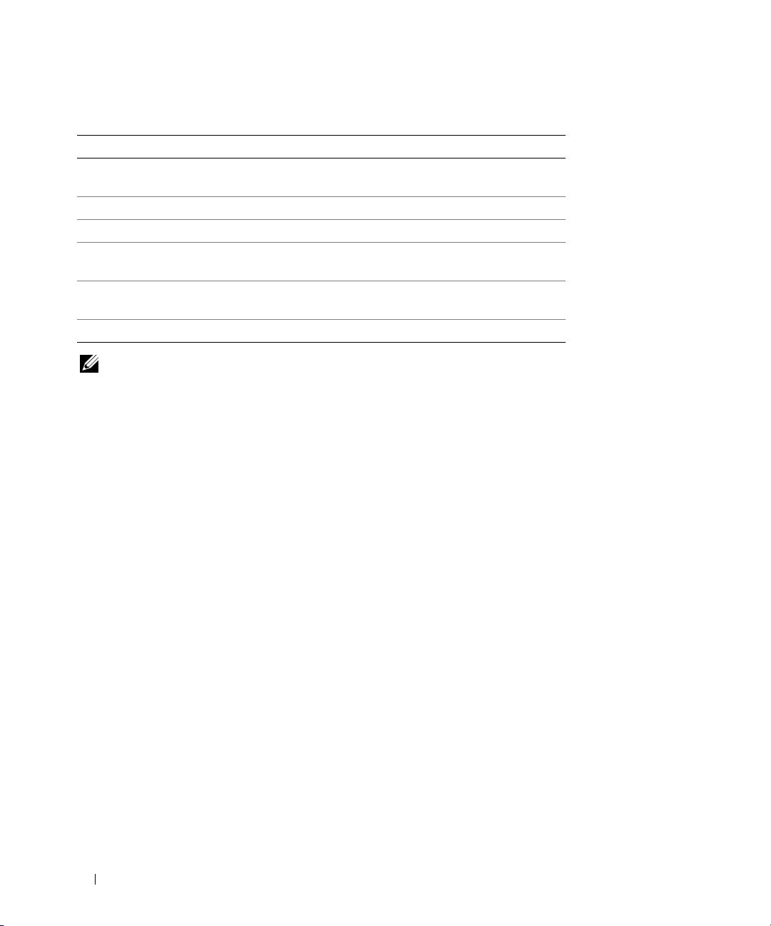
Table 2-1. System Setup Program Navigation Keys
Keys Action
<Enter> From the main menu, selects an option that has a
submenu, such as Memory Information.
Up arrow or <Shift><Tab> Moves to the previous field.
Down arrow or <Tab> Moves to the next field.
Spacebar, <+>, <
right arrows
<Esc> Exits the System Setup program and restarts the
<F1> Displays the System Setup program
NOTE: For most of the options, any changes that you make are recorded but do not take effect until you restart the
system.
–>, left and
Cycles through the settings in a field. In many fields,
you can also type the appropriate value.
system if any changes were made.
's help file.
System Setup Options
Main Screen
When you enter the System Setup program, the main System Setup program screen appears (see
Figure 2-1).
32 Using the System Setup Program
Page 33
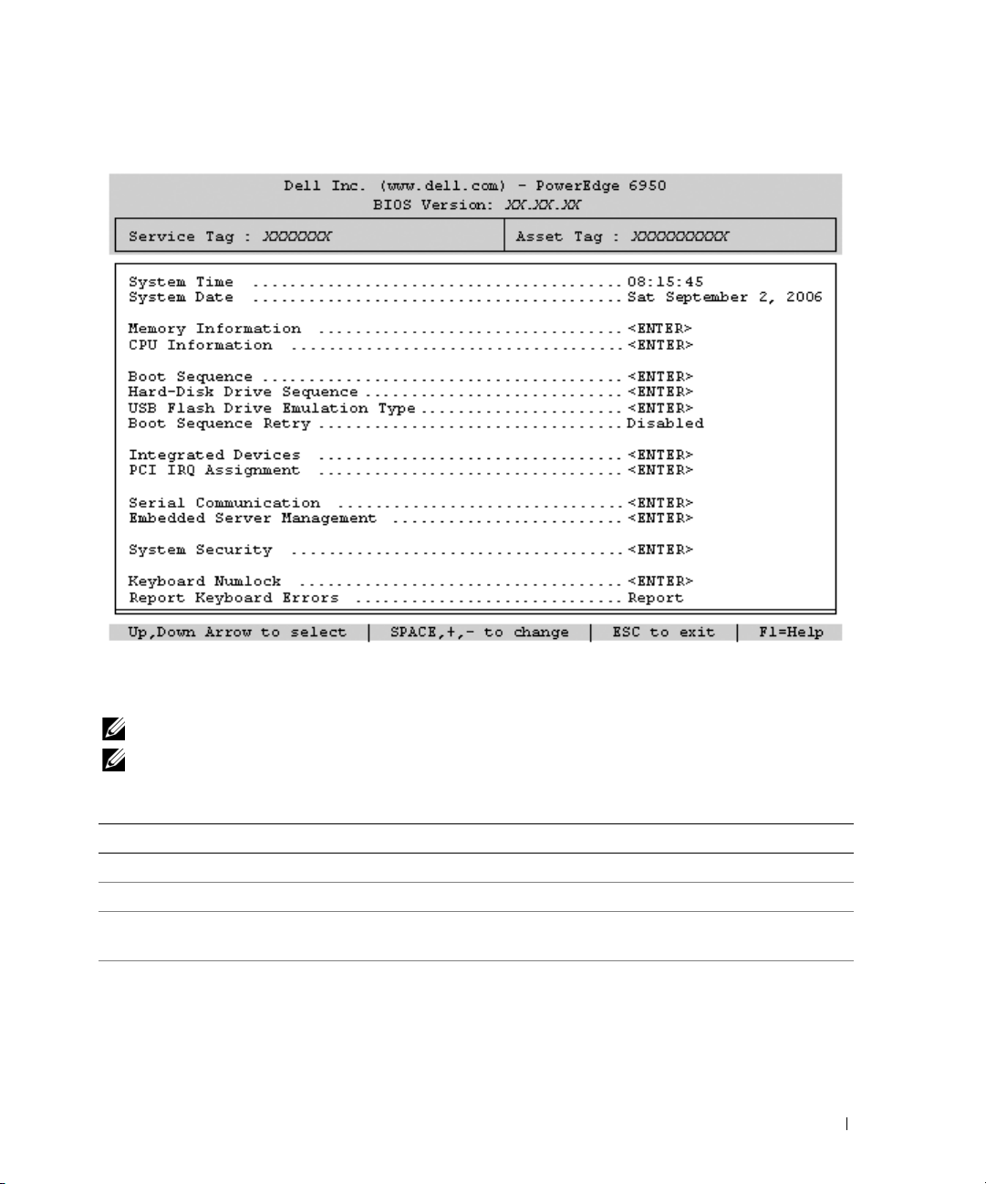
Figure 2-1. Main System Setup Program Screen
Table 2-2 lists the options and descriptions for the information fields that appear on the main System
Setup program screen. For related information, see "System Security Screen Options" on page 37.
NOTE: The options for the System Setup program change based on the system configuration.
NOTE: The System Setup program defaults are listed under their respective options, where applicable.
Table 2-2. System Setup Program Options
Option Description
System Time Resets the time on the system's internal clock.
System Date Resets the date on the system's internal calendar.
Memory Information Displays information related to installed memory. See "Memory Information
Screen" on page 35.
CPU Information Displays information related to microprocessors (speed, cache size, and so on). See
"CPU Information Screen" on page 35.
Using the System Setup Program 33
Page 34

Table 2-2. System Setup Program Options (continued)
Option Description
Boot Sequence Determines the order in which the system searches for boot devices during system
startup. Available options can include the diskette drive, CD drive, hard drives, and
network.
NOTE: System boot is not supported from an external device attached to a SAS
adapter. See support.dell.com for the latest support information about booting from
external devices.
Hard-Disk Drive
Sequence
USB Flash Drive
Emulation Type
Auto
default)
(
Boot Sequence Retry If this field is enabled and the system has failed to boot, the system will reattempt
Integrated Devices See "Integrated Devices Screen" on page 36.
PCI IRQ Assignment Displays a screen to change the IRQ assigned to each of the integrated devices on
Serial Communication
(Off default)
Embedded Server
Management
System Security Displays a screen to configure the system password and setup password features.
Keyboard NumLock
On
default)
(
Report Keyboard Errors
Report
default)
(
Determines the order in which the system searches the hard drives during system
startup. The selections depend on the hard drives installed in your system.
Determines the emulation type for a USB flash drive. Hard disk allows the USB
flash drive to act as a hard drive. Floppy allows the USB flash drive to act as a
removal diskette drive. Auto automatically chooses an emulation type.
to boot after 30 seconds.
the PCI bus, and any installed expansion card that requires an IRQ.
Options are On with Console Redirection via COM2, and Off.
Displays a screen to configure the front-panel LCD options and to set a userdefined LCD string.
See "System Security Screen" on page 37, "Using the System Password" on page 38,
and "Using the Setup Password" on page 40 for more information.
Determines whether your system starts up with the NumLock mode activated on
101- or 102-key keyboards (does not apply to 84-key keyboards).
Enables or disables reporting of keyboard errors during the POST. Select Report for
host systems that have keyboards attached. Select Do Not Report to suppress all
error messages relating to the keyboard or keyboard controller during POST. This
setting does not affect the operation of the keyboard itself if a keyboard is attached
to the system.
34 Using the System Setup Program
Page 35

Memory Information Screen
Table 2-4 lists the descriptions for the information fields that appear on the Memory Information
screen.
Table 2-3. Memory Information Screen
Option Description
System Memory Size Displays the amount of system memory.
System Memory Type Displays the type of system memory.
System Memory Speed Displays the system memory speed.
Video Memory Displays the amount of video memory.
System Memory Testing This option determines whether system memory tests are run at
system boot. Options are Enabled and Disabled.
Node Interleaving If this field is enabled, memory interleaving is supported if a
symmetric memory configuration is installed. If this field is set to
disabled (the default), the system can support Non-Uniform
Memory architecture (NUMA) (asymmetric) memory
configurations. See "General Memory Module Installation
Guidelines" on page 58.
CPU Information Screen
Table 2-4 lists the options and descriptions for the information fields that appear on the CPU
Information screen.
Table 2-4. CPU Information Screen
Option Description
64-bit Specifies if the installed processor(s) support 64-bit extensions.
Core Speed Displays the clock speed of the processor(s).
Bus Speed Displays the bus speed of the processor(s).
Demand-Based Power
Management
(Disabled default)
Processor X ID Displays the model number of the processor. A submenu displays
Enables or disables demand-based power management. When
enabled, the CPU Performance State tables will be reported to the
operating system; when disabled, the CPU Performance State
tables will not be reported to the operating system. If any of the
CPUs do not support demand-based power management, the field
will become read-only, and automatically set to Disabled.
the amount of level 2 cache and number of cores.
Using the System Setup Program 35
Page 36
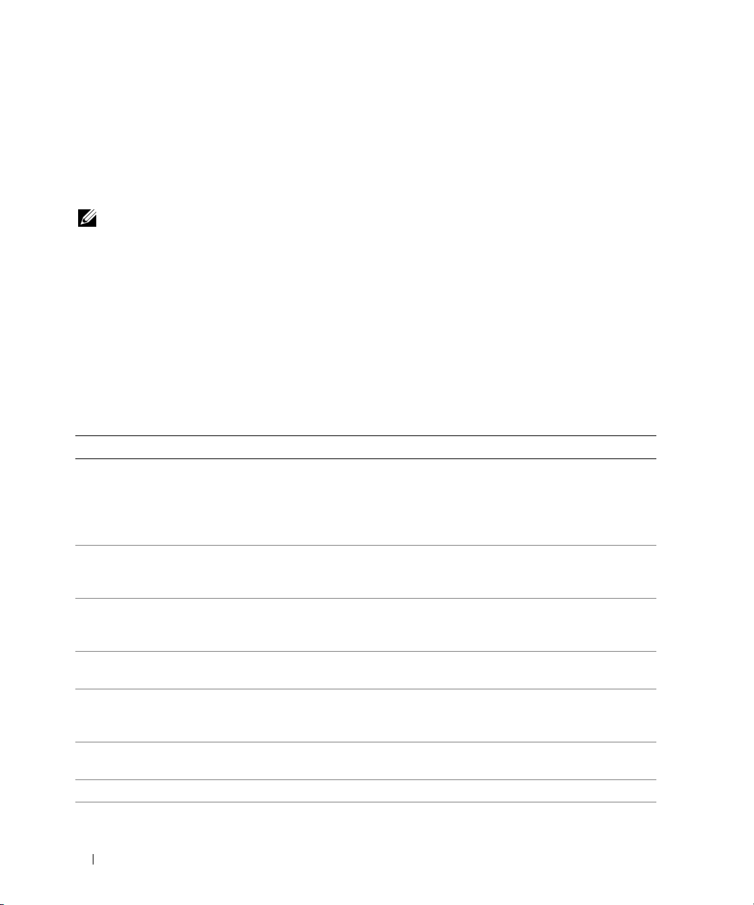
Enabling PowerNow!™ Technology
PowerNow! technology controls your system’s processor performance automatically, dynamically
adjusting the operating frequency and voltage according to the task at hand. When an application does
not require full performance, significant amounts of power can be saved. Performance is designed to still
be responsive, with maximum processor performance being delivered when required, and automatic
power savings when possible.
NOTE: PowerNow! support is dependent on the operating system and version used on your system.
To enable the PowerNow! feature, run the System Setup Program and enable the Demand-Based Power
Management option on the CPU Information screen.
Additionally, for
Microsoft® Windows® operating systems, you will need to install the PowerNow! driver
to enable this feature. The driver is available on the Dell OpenManage Service and Diagnostic CD
provided with your system, and at support.dell.com.
Integrated Devices Screen
Table 2-5 lists the options and descriptions for the information fields that appear on the Integrated
Devices screen.
Table 2-5. Integrated Devices Screen Options
Option Description
IDE CD-ROM Controller
(Auto default)
User-Accessible USB Ports
(All Ports On default)
Embedded Gb NIC1
(Enabled with PXE
default)
MAC Address Displays the MAC address for NIC1. This field does not have user-selectable
Embedded Gb NIC2
(Enabled without PXE
default)
MAC Address Displays the MAC address for NIC2. This field does not have user-selectable
TOE Capability Displays the TCP-IP Offload Engine (TOE) feature status of the NIC.
Enables the integrated IDE controller. When set to
integrated IDE controller is enabled if IDE devices are attached to the channel and
an external IDE controller is not detected.
Auto
, each channel of the
NOTE: This CD-ROM option will not appear on this menu screen if your system does
not include this optional device.
Enables or disables the system's user-accessible ports. Options are All Ports On,
Only Back Ports On, or All Ports Off. Disabling the USB ports makes system
resources available for other devices.
Enables or disables the system's integrated NIC1. Options are Enabled without
PXE, Enabled with PXE, and Disabled. PXE support allows the system to boot
from the network. Changes take effect after the system reboots.
settings.
Enables or disables the system's integrated NIC2. Options are Enabled without
PXE, Enabled with PXE, and Disabled. PXE support allows the system to boot
from the network. Changes take effect after the system reboots.
settings.
36 Using the System Setup Program
Page 37
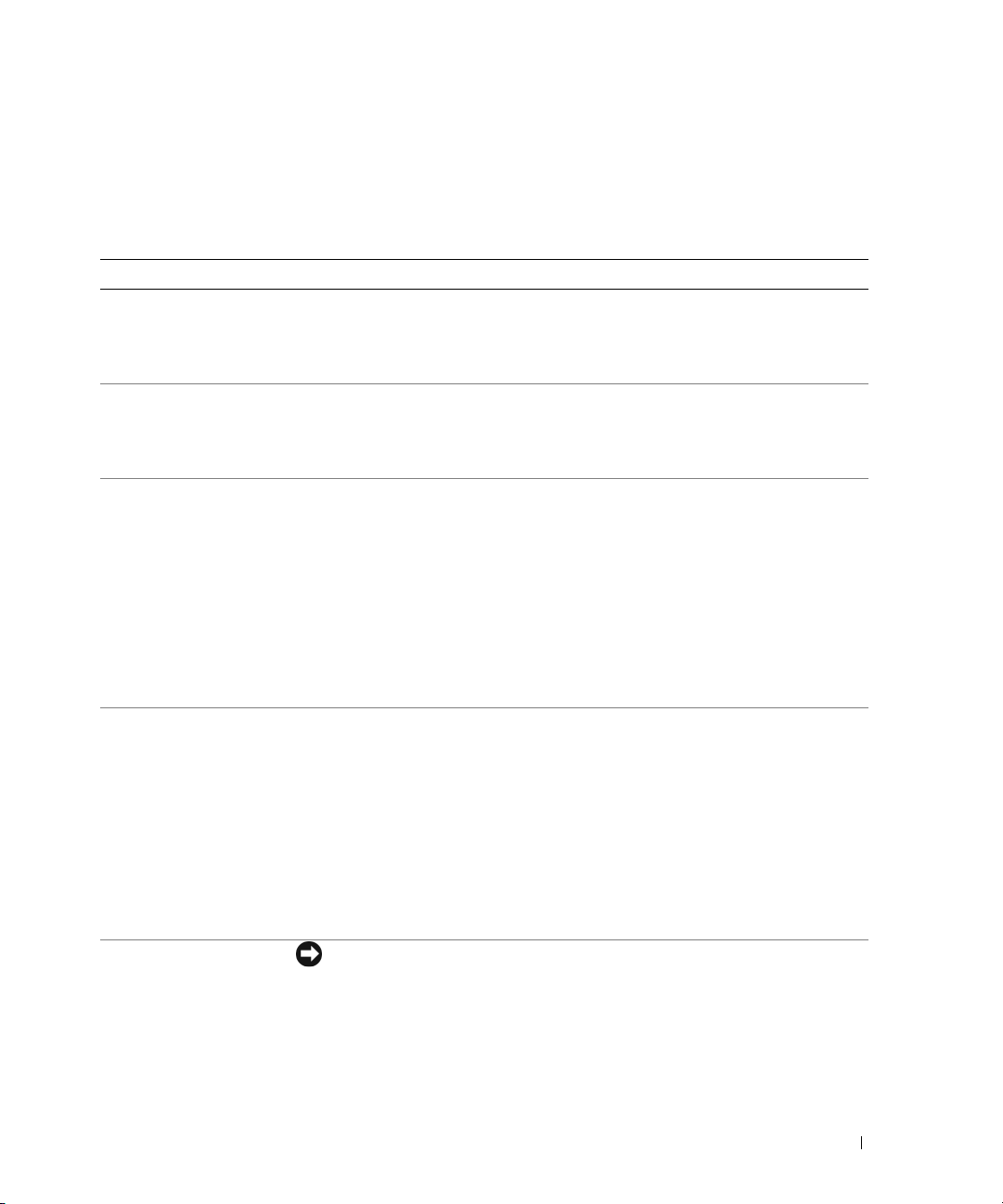
System Security Screen
Table 2-6 lists the options and descriptions for the information fields that appear on the System Security
screen.
Table 2-6. System Security Screen Options
Option Description
System Password Displays the current status of your system's password security feature and allows
you to assign and verify a new system password.
NOTE: See "Using the System Password" on page 38 for instructions on assigning a
system password and using or changing an existing system password.
Setup Password Restricts access to the System Setup program in the same way that you restrict
access to your system using the system password feature.
NOTE: See "Using the Setup Password" on page 40 for instructions on assigning a
setup password and using or changing an existing setup password.
Password Status Setting the Setup Password option to Enabled prevents the system password from
being changed or disabled at system start-up.
To lock the system password, assign a setup password in the Setup Password option
and then change the Password Status option to Locked. In this state, you cannot
change the system password using the System Password option and cannot be
disabled at system start-up by pressing <Ctrl><Enter>.
To unlock the system password, enter the setup password in the Setup Password
field and then change the Password Status option to Unlocked. In this state, you
can disable the system password at system start-up by pressing <Ctrl><Enter>
and then change the password using the System Password option.
Power Button
NMI Button
Turns system's power off and on.
• If you turn off the system using the power button and the system is running an
ACPI-compliant operating system, the system can perform an orderly shutdown
before power is turned off.
• If the system is not running an ACPI-compliant operating system, power is turned
off immediately after the power button is pressed.
The button is enabled in the System Setup program. When disabled, the button
can only turn on system power.
NOTE: You can still turn on the system by using the power button, even if the Power
Button option is set to Disabled.
NOTICE: Use the NMI button only if directed to do so by qualified support
personnel or by the operating system's documentation. Pressing this button
halts the operating system and displays a diagnostic screen.
Enables or disables the NMI feature.
Using the System Setup Program 37
Page 38
Table 2-6. System Security Screen Options (continued)
Option Description
AC Power Recovery
(Last default)
Determines how the system reacts when power is restored to the system. If system
is set to Last, the system returns to the last power state. On turns on the system
after power is restored. When set to Off, the system remains off after power is
restored.
Exit Screen
After you press <Esc> to exit the System Setup program, the Exit screen displays the following options:
•
Save Changes and Exit
• Discard Changes and Exit
• Return to Setup
System and Setup Password Features
NOTICE: The password features provide a basic level of security for the data on your system. If your data requires
more security, use additional forms of protection, such as data encryption programs.
NOTICE: Anyone can access the data stored on your system if you leave the system running and unattended
without having a system password assigned or if you leave your system unlocked so that someone can disable the
password by changing a jumper setting.
Your system is shipped to you without the system password feature enabled. If system security is a
concern, operate your system only with system password protection.
To change or delete an existing password, you must know the password (see "Deleting or Changing an
Existing System Password" on page 40). If you forget your password, you cannot operate your system or
change settings in the System Setup program until a trained service technician changes the password
jumper setting to disable the passwords, and erases the existing passwords. This procedure is described in
"Disabling a Forgotten Password" on page 123.
Using the System Password
After a system password is assigned, only those who know the password have full use of the system.
When the System Password option is set to Enabled, the system prompts you for the system password
after the system starts.
Assigning a System Password
Before you assign a system password, enter the System Setup program and check the System Password
option.
38 Using the System Setup Program
Page 39

When a system password is assigned, the setting shown for the System Password option is Enabled. If
the setting shown for the Password Status is Unlocked, you can change the system password. If the
Password Status option is Locked, you cannot change the system password. When the system password
feature is disabled by a jumper setting, the system password is Disabled, and you cannot change or enter
a new system password.
When a system password is not assigned and the password jumper on the system board is in the enabled
(default) position, the setting shown for the System Password option is Not Enabled and the Password
Status field is Unlocked. To assign a system password:
1
Verify that the
2
Highlight the
3
Type your new system password.
Password Status
System Password
option is set to
Unlocked
.
option and press <Enter>.
You can use up to 32 characters in your password.
As you press each character key (or the spacebar for a blank space), a placeholder appears in the field.
The password assignment is not case-sensitive. However, certain key combinations are not valid. To
erase a character when entering your password, press <Backspace> or the left-arrow key.
NOTE: To escape from the field without assigning a system password, press <Enter> to move to another field,
or press <Esc> at any time prior to completing step 5.
4
Press <Enter>.
5
To confirm your password, type it a second time and press <Enter>.
The setting shown for the
System Password
changes to
Enabled
. Exit the System Setup program and
begin using your system.
6
Either reboot your system now for your password protection to take effect or continue working.
NOTE: Password protection does not take effect until you reboot the system.
Using Your System Password to Secure Your System
NOTE: If you have assigned a setup password (see "Using the Setup Password" on page 40"), the system accepts
your setup password as an alternate system password.
When the Password Status option is set to Unlocked, you have the option to leave the password security
enabled or to disable the password security.
To leave the password security enabled:
1
Turn on or reboot your system by pressing <Ctrl><Alt><Del>.
2
Type your password and press <Enter>.
To disable the password security:
1
Turn on or reboot your system by pressing <Ctrl><Alt><Del>.
2
Type your password and press <Ctrl><Enter>.
Using the System Setup Program 39
Page 40
When the Password Status option is set to Locked whenever you turn on your system or reboot your
system by pressing <Ctrl><Alt><Del>, type your password and press <Enter> at the prompt.
After you type the correct system password and press <Enter>, your system operates as usual.
If an incorrect system password is entered, the system displays a message and prompts you to re-enter
your password. You have three attempts to enter the correct password. After the third unsuccessful
attempt, the system displays an error message showing the number of unsuccessful attempts and that
the system has halted and will shut down. This message can alert you to an unauthorized person
attempting to use your system.
Even after you shut down and restart the system, the error message continues to be displayed until the
correct password is entered.
NOTE: You can use the Password Status option in conjunction with the System Password and Setup Password
options to further protect your system from unauthorized changes.
Deleting or Changing an Existing System Password
1
When prompted, press <Ctrl><Enter> to disable the existing system password.
If you are asked to enter your setup password, contact your network administrator.
2
Enter the System Setup program by pressing <F2> during POST.
3
Select the
4
When prompted, type the system password.
5
Confirm that
If
Not Enabled
Enabled
System Security
Not Enabled
is displayed for the
is displayed for the
screen field to verify that the
is displayed for the
System Password
System Password
System Password
option, the system password has been deleted. If
option, press the <Alt><b> key combination to restart
Password Status
option.
option is set to
Unlocked
the system, and then repeat steps 2 through 5.
.
Using the Setup Password
Read the information in the following sections to assign or change your setup password.
Assigning a Setup Password
You can assign (or change) a setup password only when the Setup Password option is set to Not Enabled.
To assign a setup password, highlight the Setup Password option and press the <+> or <–> key. The
system prompts you to enter and verify the password. If a character is illegal for password use, the system
beeps.
NOTE: The setup password can be the same as the system password. If the two passwords are different, the setup
password can be used as an alternate system password. However, the system password cannot be used in place of
the setup password.
You can use up to 32 characters in your password.
As you press each character key (or the spacebar for a blank space), a placeholder appears in the field.
40 Using the System Setup Program
Page 41
The password assignment is not case-sensitive. However, certain key combinations are not valid. If you
enter one of these combinations, the system beeps. To erase a character when entering your password,
press <Backspace> or the left-arrow key.
After you verify the password, the Setup Password setting changes to Enabled. The next time you enter
the System Setup program, the system prompts you for the setup password.
A change to the Setup Password option becomes effective immediately (restarting the system is not
required).
Operating With a Setup Password Enabled
If Setup Password is set to Enabled, you must enter the correct setup password before you can modify
most of the System Setup options. When you start the System Setup program, the program prompts you
to enter a password.
If you do not enter the correct password in three attempts, the system lets you view, but not modify, the
System Setup screens—with the following exception: If System Password is not set to Enabled and is not
locked through the Password Status option, you can assign a system password.
NOTE: You can use the Password Status option in conjunction with the Setup Password option to protect the
system password from unauthorized changes.
Deleting or Changing an Existing Setup Password
1
Enter the System Setup program and select the
2
Highlight the
<Enter> twice to clear the existing setup password.
The setting changes to
Setup Password
Not Enabled
option, press <Enter> to access the setup password window, and press
.
System Security
option.
3
If you want to assign a new setup password, perform the steps in "Assigning a Setup Password" on
page 40.
Disabling a Forgotten Password
See "Disabling a Forgotten Password" on page 123.
Baseboard Management Controller Configuration
The Baseboard Management Controller (BMC) enables configuring, monitoring, and recovery of systems
remotely. BMC provides the following features:
• Uses the system’s integrated NIC
• Fault logging and SNMP alerting
• Access to system event log and sensor status
• Control of system functions including power on and off
Using the System Setup Program 41
Page 42

• Support is independent of the system’s power or operating state
• Provides text console redirection for system setup, text-based utilities, and operating system consoles
NOTE: To remotely access the BMC through the integrated NIC, you must connect the network connection to
integrated NIC1.
For additional information on using BMC, see the documentation for the BMC and systems management
applications.
Entering the BMC Setup Module
1
Turn on or restart your system.
2
Press <
If your operating system begins to load before you press <
booting, and then restart your system and try again.
Ctrl-E
> when prompted after POST.
Crtl-E
>, allow the system to finish
BMC Setup Module Options
For information about the BMC Setup Module options and how to configure the emergency management
port (EMP), see the
BMC User’s Guide
.
42 Using the System Setup Program
Page 43

Installing System Components
This section describes how to install the following system components:
• Front bezel
• System cover
• Cooling fan modules
• Cooling shrouds
• Power supplies
• Expansion cards
• RAC card
• System memory
• Processors
• Diskette drive
• Optical drive
• Hard drives
• SAS controller card
• RAID battery
• External SAS tape drive
• External Fibre Channel device
• System battery
• Control panel assembly
• Fan interposer board
• Power distribution board
• Chassis intrusion switch
• SAS backplane board
• System board
Installing System Components 43
Page 44
Recommended Tools
You may need the following items to perform the procedures in this section:
• Key to the system keylock
• #2 Phillips screwdriver
• T10 Torx driver
• Small flat-blade screwdriver
• Wrist grounding strap
Inside the System
CAUTION: Only trained service technicians are authorized to remove the system cover and access any of the
components inside the system. See your Product Information Guide for complete information about safety
precautions, working inside the computer, and protecting against electrostatic discharge.
In Figure 3-1, the bezel, system cover, and cooling shrouds are removed to provide an interior view of the
system.
NOTICE: Do not remove the cooling shrouds if the system is turned on. The cooling shrouds must be installed to
direct the airflow from the fans.
44 Installing System Components
Page 45
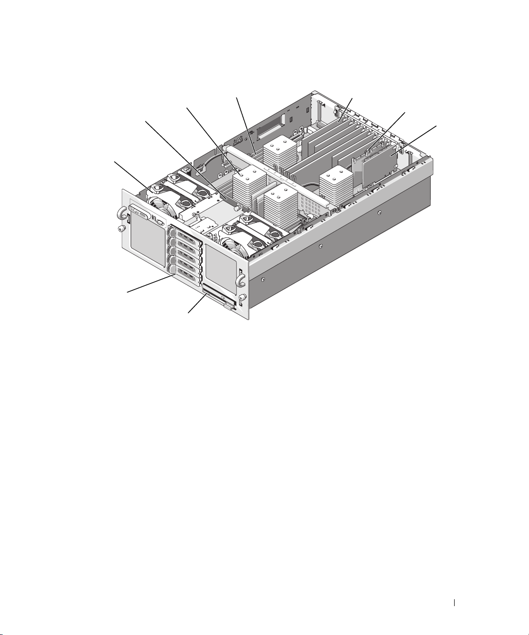
Figure 3-1. Inside the System
4
3
2
1
9
8
1 fan modules (4) 2 SAS backplane 3 heatsink/processor (4)
4 memory modules (16) 5 expansion cards (7) 6 SAS controller card
7 optional RAC 8 optical slimline drive (optional) 9 optional 3.5-inch hard
5
6
drives (5)
7
The system board holds the system's control circuitry and other electronic components. The processors
and memory modules are installed directly on the system board.
The hard-drive bays provide space for up to five optional 3.5-inch SAS hard drives. The hard drives
connect to a SAS controller card or an optional SAS RAID controller card through a SAS backplane.
A
removable drive carrier supports an optional diskette drive and optional optical drive.
Removing and Replacing the Optional Front Bezel
1
Unlock the keylock at the left end of the bezel.
2
Rotate the left end of the bezel away from the front panel.
3
Unhook the right end of the bezel and pull the bezel away from the system.
Installing System Components 45
Page 46
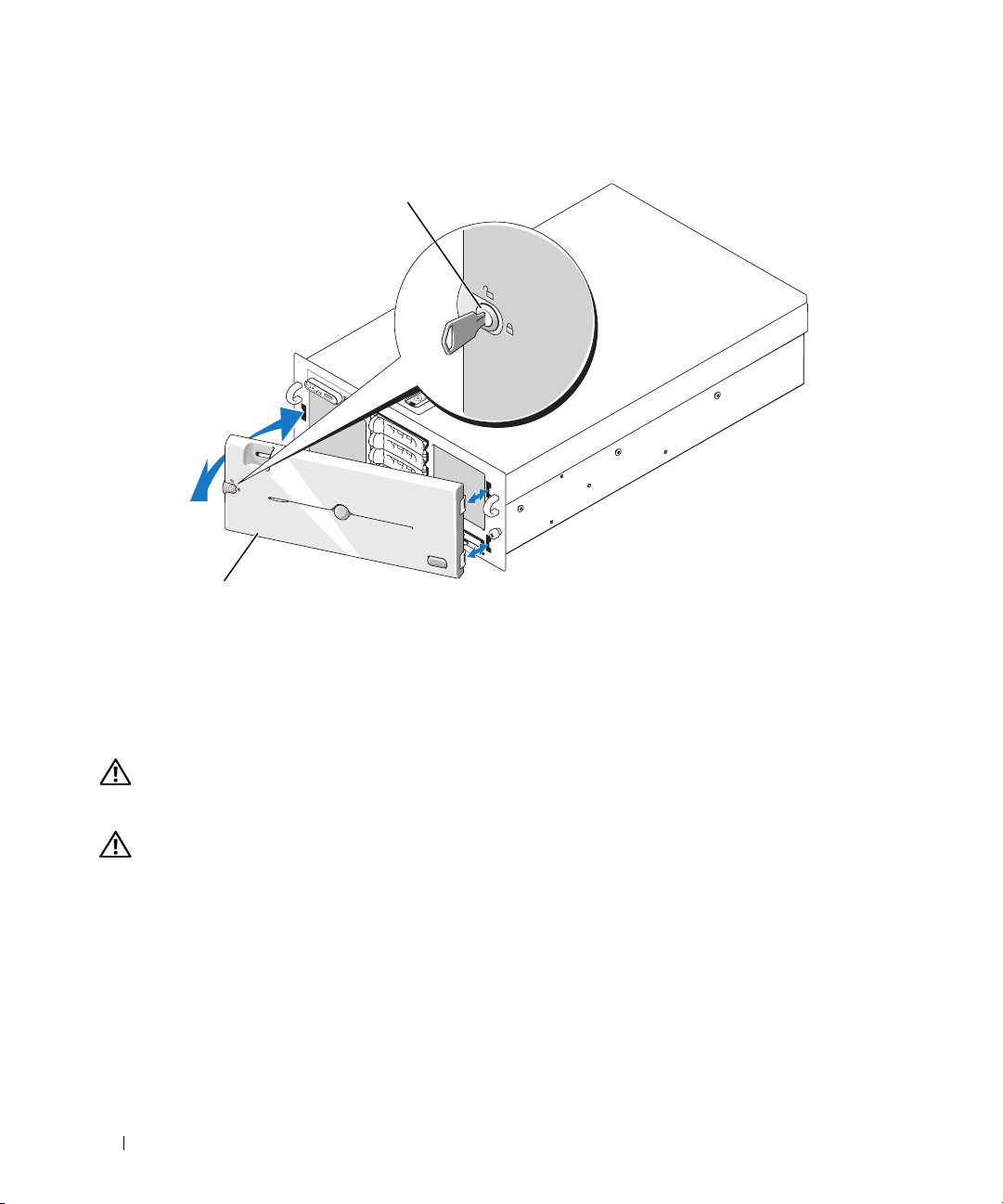
Figure 3-2. Removing and Replacing the Optional Front Bezel
1
2
1 key lock 2 bezel
To replace the optional bezel, hook the right end of the bezel onto the chassis, then fit the free end of the
bezel onto the system. Secure the bezel with the keylock. See Figure 3-2.
Opening and Closing the System
CAUTION: Only trained service technicians are authorized to remove the system cover and access any of the
components inside the system. See your Product Information Guide for complete information about safety
precautions, working inside the computer, and protecting against electrostatic discharge.
CAUTION: Whenever you need to lift the system, get others to assist you. To avoid injury, do not attempt to lift the
system by yourself.
Opening the System
1
Unless you are installing a hot-plug component such as a cooling fan or hard-disk drive, turn off the
system and attached peripherals, and disconnect the system from the electrical outlet and peripherals.
2
Rotate the latch release lock on the latch in a counter clockwise direction to the unlocked position. See
Figure 3-3.
3
Lift up on the latch on top of the system and slide the cover back. See Figure 3-3.
4
Grasp the cover on both sides and carefully lift the cover away from the system.
46 Installing System Components
Page 47
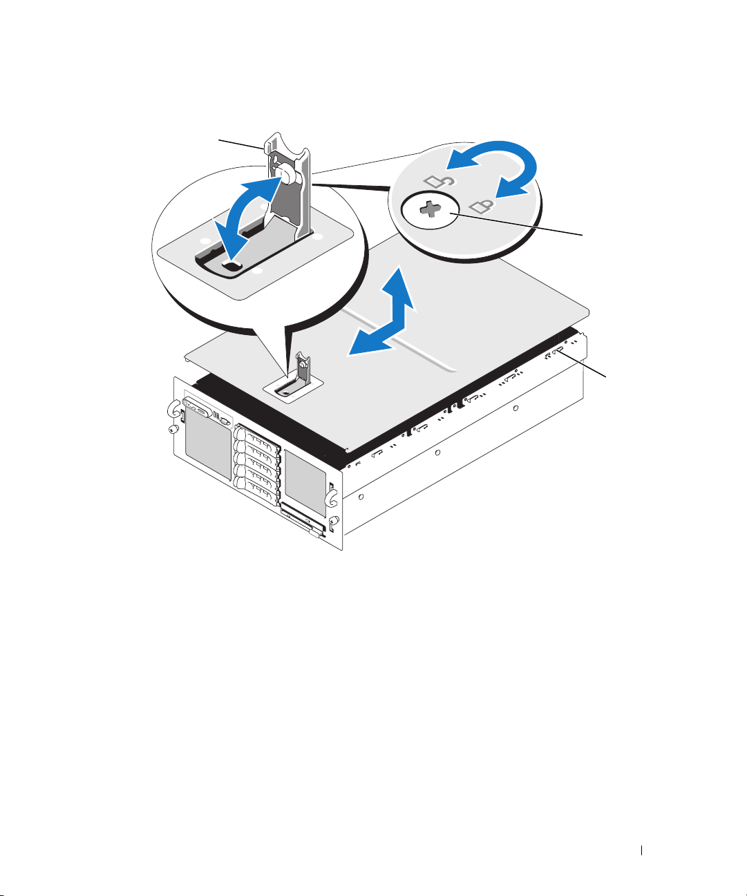
Figure 3-3. Removing and Replacing the System Cover
1
2
3
1 latch 2 latch release lock 3 J hooks
Closing the System
1
Lift up the latch on the cover.
2
Align the cover with the left and right edges of the system and offset it slightly towards the back of the
system, so that the pins on the inner edge of the cover are aligned with the chassis J hooks. See
Figure 3-3.
3
Lower the cover onto the chassis and close the latch.
4
Rotate the latch release lock in a clockwise direction to secure the cover.
Installing System Components 47
Page 48
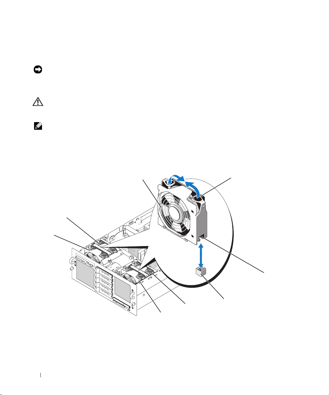
Cooling Fans
This system contains four hot-plug cooling fans, connected directly to the system board.
NOTICE: In the event of a problem with a particular fan, the fan’s number is referenced by the system’s
management software, allowing you to easily identify and replace the proper fan.
Removing a Cooling Fan
CAUTION: Only trained service technicians are authorized to remove the system cover and access any of the
components inside the system. See your Product Information Guide for complete information about safety
precautions, working inside the computer, and protecting against electrostatic discharge.
NOTE: The procedure for removing each individual fan module is the same.
1
Open the system. See "Opening the System" on page 46.
2
Compress the two latches on the top of the fan, then remove the fan. See Figure 3-4.
Figure 3-4. Removing and Replacing a Cooling Fan
1
8
7
5
6
1 fan 2 latches (2) 3 fan power connector
4 fan-bay power connector 5 FAN4 6 FAN2
7FAN1 8 FAN3
2
4
3
48 Installing System Components
Page 49

Replacing a Cooling Fan
NOTE: The procedure for installing each individual fan is the same.
1
Ensure that the fan handle is upright and lower the fan into its retention base until the fan is fully
seated. Then lower the fan handle until it snaps into place. See Figure 3-4.
2
Close the system. See "Closing the System" on page 47.
Cooling Shrouds
The three cooling shrouds direct airflow within the system.
Removing the Cooling Shrouds
NOTICE: Do not remove the cooling shrouds if the system is turned on. The cooling shrouds must be installed to
direct the airflow from the fans.
1
First, remove the top cooling shroud by using the finger holes to lift the shroud straight up from the
system. See Figure 3-5.
2
Remove the left and right cooling shrouds as necessary to access the interior of the system.
Installing System Components 49
Page 50
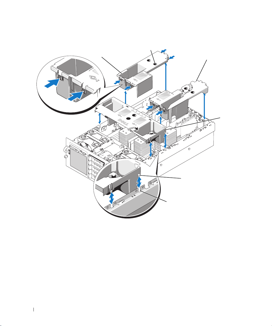
Figure 3-5. Removing and Replacing the Cooling Shrouds
1
2
3
4
5
6
1 left cooling shroud 2 finger holes 3 right cooling shroud
4 top cooling shroud 5 guide 6 slot
Replacing the Cooling Shrouds
1
Slowly lower the left shroud straight down into the system. The guides on the edges of the shroud fit
into the corresponding slots in the sides of the chassis. See Figure 3-5.
2
Gently press down on the shroud until it is fully seated.
3
Install the right shroud.
4
Install the top shroud.
50 Installing System Components
Page 51
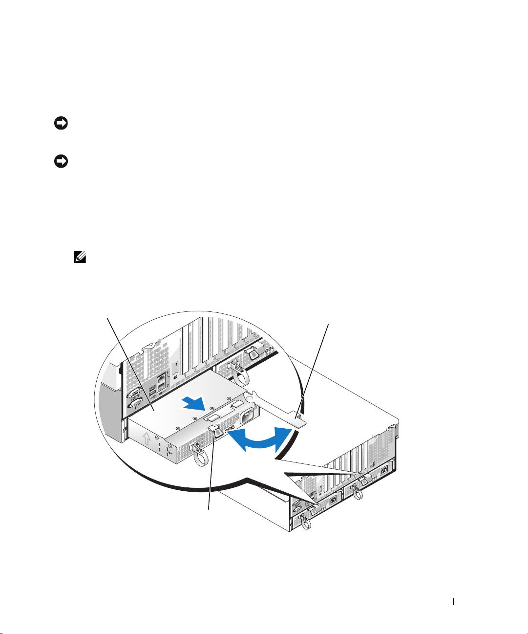
Power Supplies
Your system supports two power supplies rated at an output of 1570 W. The second power supply serves
as a redundant, hot-plug power source.
NOTICE: The system is only in the redundant mode when two power supplies are installed and both power
supplies are connected to an AC power source. If some third-party components (such as PCI cards) not tested or
supported by Dell are installed, the power supplies may not be redundant at all input voltages.
NOTICE: Operating the system with only one power supply installed for extended periods of time can cause the
system to overheat.
Removing a Power Supply
1
Disconnect the power cable from the power source and the power supply you intend to remove.
2
Press the lever release latch, then open the release lever and slide the power supply out of the chassis.
See Figure 3-6.
NOTE: You may have to unlatch and lift the cable management arm if it interferes with power-supply removal.
For information about the cable management arm, see the system’s Rack Installation Guide.
Figure 3-6. Removing and Replacing a Power Supply
1
3
1 power supply 2 release lever 3 lever release latch
2
Installing System Components 51
Page 52

Replacing a Power Supply
1
Holding the lever in the open position, slide the new power supply into the chassis until the lever
contacts the system chassis. See Figure 3-6.
2
Close the release lever until the power supply is fully seated and the lever snaps into place behind the
lever release latch. See Figure 3-6.
NOTE: If you unlatched the cable management arm in step 2 of the previous procedure, relatch it. For
information about the cable management arm, see the system’s Rack Installation Guide.
3
Connect the power cable to the power supply and plug the cable into a power outlet.
NOTICE: When connecting the power cable, insert the cable through the strain-relief loop.
NOTE: After installing a new power supply in a system with two power supplies, allow several seconds for the
system to recognize the power supply and determine its status. The power-supply status indicator turns green to
signify that the power supply is functioning properly (see Figure 1-4).
Expansion Cards
Expansion Card Installation Guidelines
Your system supports up to eight PCI-Express (PCIe) expansion cards installed in connectors on the
system board (see Figure 3-7 and Table 3-1):
• Slots 1 and 2 are x4 lane-width PCIe expansion slots. Slot 2 accommodates a full-length card.
• Slots 3 and 4 are x8 lane-width PCIe expansion slots. Both slots accommodate full-length cards.
• Slots 5 through 7 are x4 lane-width PCIe expansion slots. Slot 5 accommodates a full-length card.
• One expansion slot, labeled INTERNAL_STORAGE, is reserved for the system’s SAS controller card.
• If you are installing a Remote Access Control (RAC) card, it must be installed in the special card slot
marked RAC_CONN. See "RAC Card" on page 56
52 Installing System Components
Page 53
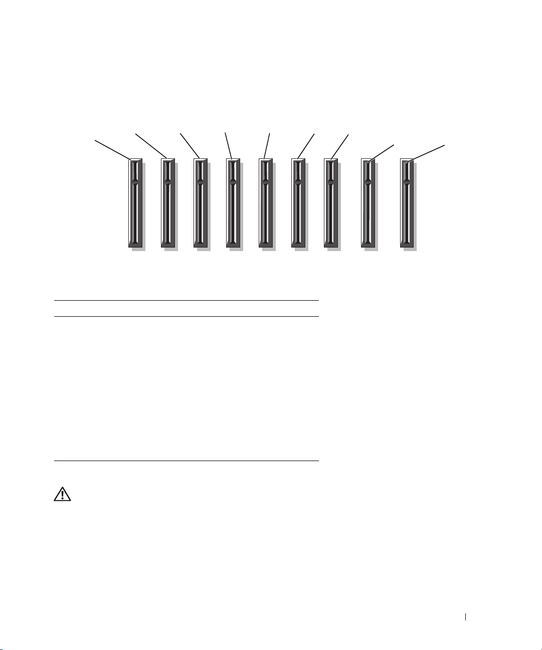
Figure 3-7. Expansion Slots
back of system
SLOT 7
Table 3-1. Expansion Slots
Slot Description
SLOT 1 x4 lane-width PCIe
SLOT 2 x4 lane-width PCIe
SLOT 3 x8 lane-width PCIe
SLOT 4 x8 lane-width PCIe
SLOT 5 x4 lane-width PCIe
SLOT 6 x4 lane-width PCIe
SLOT 7 x4 lane-width PCIe
INTERNAL_STORAGE reserved for controller cards
RAC_CONN reserved for RAC card
SLOT 6
SLOT 5
SLOT 4 SLOT 3
front of system
SLOT 2
SLOT 1
INTERNAL_
STORAGE
RAC_CONN
Installing an Expansion Card
CAUTION: Only trained service technicians are authorized to remove the system cover and access any of the
components inside the system. See your Product Information Guide for complete information about safety
precautions, working inside the computer, and protecting against electrostatic discharge.
1
Unpack the expansion card and prepare it for installation.
For instructions, see the documentation accompanying the card.
2
Turn off the system, including any attached peripherals, and disconnect the system from the electrical
outlet.
Installing System Components 53
Page 54

3
Open the system. See "Opening the System" on page 46.
4
If you are adding a new card, select the appropriate expansion card slot. See "Expansion Card
Installation Guidelines" on page 52.
5
Open the expansion-card retainer and remove the filler bracket. See Figure 3-8.
6
Install the expansion card:
a
Holding the card by its edges, position the card so that the card-edge connector aligns with the
expansion-card connector on the system board.
NOTICE: If you are installing a SAS RAID controller card, do not press on the memory module when installing the
card.
Insert the card-edge connector firmly into the expansion-card connector until the card is fully
b
seated.
c
Close the expansion-card retainer. See Figure 3-8.
54 Installing System Components
Page 55
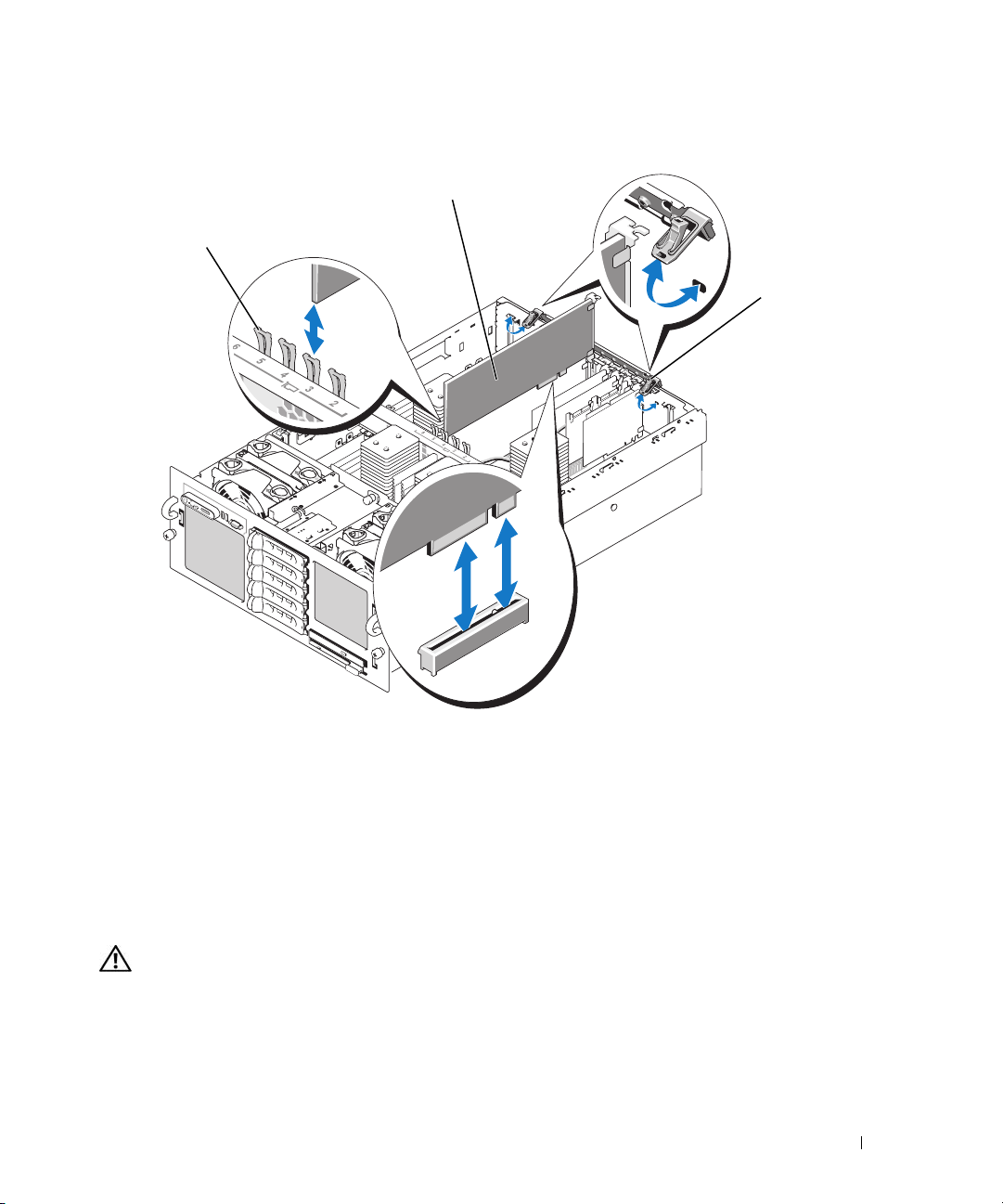
Figure 3-8. Installing or Removing an Expansion Card
2
1
3
1 card-edge guide (full-length
cards only)
7
Connect any cables to the expansion card.
2 expansion card 3 expansion-card retainer
• If you are installing a RAC card, see "RAC Card" on page 56.
• If you are installing a SAS controller card, see "Installing a SAS Controller Card" on page 76.
8
Close the system. See "Closing the System" on page 47.
Removing an Expansion Card
CAUTION: Only trained service technicians are authorized to remove the system cover and access any of the
components inside the system. See your Product Information Guide for complete information about safety
precautions, working inside the computer, and protecting against electrostatic discharge.
1
Turn off the system, including any attached peripherals, and disconnect the system from the electrical
outlet.
2
Open the system. See "Opening the System" on page 46.
Installing System Components 55
Page 56

3
Disconnect all cables from the card.
4
Remove the expansion card:
a
Open the expansion-card retainer. See Figure 3-8.
b
Grasp the expansion card by its edges, and carefully remove it from the expansion-card connector.
5
If you are removing the card permanently, install a metal filler bracket over the empty expansion slot
opening and close the expansion-card retainer.
NOTE: You must install a filler bracket over an empty expansion slot to maintain Federal Communications
Commission (FCC) certification of the system. The brackets also keep dust and dirt out of the system and aid in
proper cooling and airflow inside the system.
6
Close the system. See "Closing the System" on page 47.
RAC Card
1
Unpack the RAC card and prepare it for installation.
For instructions, see the documentation accompanying the card.
2
Turn off the system, including any attached peripherals, and disconnect the system from the electrical
outlet.
3
Open the system. See "Opening the System" on page 46.
4
Remove the cooling shrouds. See "Removing the Cooling Shrouds" on page 49.
5
Remove the plastic filler plug from the system back panel. See Figure 1-3.
6
Remove the storage controller card from the expansion slot labeled INTERNAL STORAGE:
a
Disconnect all data cables from the card.
b
Grasp the storage controller card by its edges, and carefully remove it from the card connector.
7
Install the RAC card in the slot labeled RAC_CONN:
a
Angle the RAC card so that the NIC connector inserts through the back-panel RAC card opening.
Figure 3-9.
See
b
Position the card so that the card-edge connector aligns with the expansion-card connector.
c
Insert the card-edge connector firmly into the expansion-card connector until the card is fully
seated.
8
Connect the 50-pin management cable and the 44-pin MII cable supplied with the RAC to the two
connectors on the RAC card (see Figure 3-9), and to the two corresponding connectors on the system
board.
56 Installing System Components
Page 57
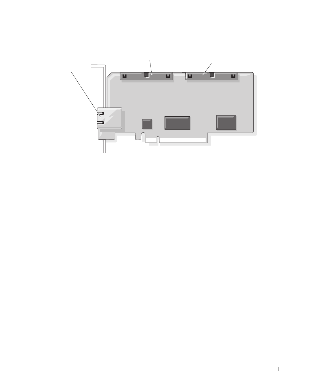
Figure 3-9. RAC Card Connectors
1
1 RJ-45 connector 2 44-pin MII cable connector 3 50-pin management cable
9
Reinstall the storage controller card.
10
Reinstall the cooling shrouds. See "Replacing the Cooling Shrouds" on page 50.
11
Reconnect all cables to the storage controller card and feed the cables through the appropriate
2
3
connector
channels and keepers on the cooling shrouds.
12
Close the system. See "Closing the System" on page 47.
13
Reconnect the system and peripherals to their power sources, and turn them on.
14
Enter the System Setup program and verify that the setting for the Boot Sequence has changed to
reflect the presence of the RAC card. See "Using the System Setup Program" in your
Manual
15
Exit the System Setup program and reboot the system.
When the system boots, the
.
Remote Access Control Detected
message displays and the
Hardware Owner’s
option ROM and firmware information for the RAC displays.
Press <Ctrl><e> to enter the RAC configuration screen. See the RAC documentation for
information on configuring and using the RAC.
System Memory
You can upgrade your system memory to a maximum of 32 GB (two-processor configurations) or 64 GB
(four-processor configurations) by installing 667-MHz registered DDR-II memory modules (DIMMs) in
sets of 512-MB, 1-GB, 2-GB, or 4-GB modules. The sixteen memory sockets are located on the system
board under the cooling shrouds. Each processor has four memory channels, organized in sets of two.
Installing System Components 57
Page 58

Your system hardware supports Non-Uniform Memory Architecture (NUMA). Each processor has its own
memory controller and local memory for reduced access times, but it can also access memory from
another processor. This architecture improves system performance if an operating system is installed that
supports this feature.
NOTICE: To enable NUMA, run the System Setup program and disable the Node Interleaving option. See "Using
the System Setup Program" on page 31.
General Memory Module Installation Guidelines
To ensure optimal performance of your system, observe the following guidelines when configuring your
system memory.
• Memory modules m
DIMM5 and DIMM6 (processor 2), DIMM9 and DIMM10 (processor 3), and DIMM13 and DIMM14
(processor 4).
• The memory modules must be identical in speed and technology. The DIMMs in each pair must be
the same size.
Memory can either be installed in a two-processor configuration (Table 3-2) or a four-processor
configuration (Table 3-3).
ust be installed in pairs
, beginning with DIMM1 and DIMM2 (processor 1)
58 Installing System Components
Page 59
Table 3-2. Two-Processor Memory Configurations
Total
System
Memory
DIMM1 DIMM2 DIMM3 DIMM4 DIMM5 DIMM6 DIMM7 DIMM8
CPU 1 CPU2
2 GB 512 MB 512 MB 512 MB 512 MB
4 GB 512 MB 512 MB 512 MB 512 MB 512 MB 512 MB 512 MB 512 MB
4 GB 1 GB 1 GB 1 GB 1 GB
6 GB 1 GB 1 GB 512 MB 512 MB 1 GB 1 GB 512 MB 512 MB
8 GB 1 GB 1 GB 1 GB 1 GB 1 GB 1 GB 1 GB 1 GB
8 GB 2 GB 2 GB 2 GB 2 GB
16 GB 2 GB 2 GB 2 GB 2 GB 2 GB 2 GB 2 GB 2 GB
16 GB 4 GB 4 GB 4 GB 4 GB
24 GB 4 GB 4 GB 2 GB 2 GB 4 GB 4 GB 2 GB 2 GB
32 GB 4 GB 4 GB 4 GB 4 GB 4 GB 4 GB 4 GB 4 GB
Table 3-3. Four-Processor Memory Configurations
Total CPU1 CPU2 CPU3 CPU4
System DIMM DIMM DIMM DIMM
Memory 12345678910111213141516
4GB 512 MB512
MB
512 MB512
MB
512 MB512
MB
512 MB512
MB
8 GB 512 MB512 MB512 MB512 MB512 MB512 MB512 MB512 MB512 MB512 MB512 MB512 MB512 MB512 MB512 MB512
MB
8 GB 1 GB 1 GB 1 GB 1 GB 1 GB 1 GB 1 GB 1 GB
12 GB 1 GB 1 GB 512 MB512 MB1 GB 1 GB 512 MB512 MB1 GB 1 GB 512 MB512 MB1 GB 1 GB 512 MB512
MB
16 GB 1 GB 1 GB 1 GB 1 GB 1 GB 1 GB 1 GB 1 GB 1 GB 1 GB 1 GB 1 GB 1 GB 1 GB 1 GB 1 GB
16 GB 2 GB 2 GB 2 GB 2 GB 2 GB 2 GB 2 GB 2 GB
24 GB 2 GB 2 GB 1 GB 1 GB 2 GB 2 GB 1 GB 1 GB 2 GB 2 GB 1 GB 1 GB 2 GB 2 GB 1 GB 1 GB
32 GB 2 GB 2 GB 2 GB 2 GB 2 GB 2 GB 2 GB 2 GB 2 GB 2 GB 2 GB 2 GB 2 GB 2 GB 2 GB 2 GB
32 GB 4 GB 4 GB 4 GB 4 GB 4 GB 4 GB 4 GB 4 GB
48 GB 4 GB 4 GB 2 GB 2 GB 4 GB 4 GB 2 GB 2 GB 4 GB 4 GB 2 GB 2 GB 4 GB 4 GB 2 GB 2 GB
64 GB 4 GB 4 GB 4 GB 4 GB 4 GB 4 GB 4 GB 4 GB 4 GB 4 GB 4 GB 4 GB 4 GB 4 GB 4 GB 4 GB
Installing System Components 59
Page 60
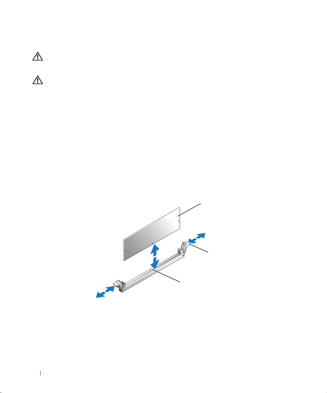
Installing Memory Modules
CAUTION: Only trained service technicians are authorized to remove the system cover and access any of the
components inside the system. See your Product Information Guide for complete information about safety
precautions, working inside the computer, and protecting against electrostatic discharge.
CAUTION: The memory modules are hot to the touch for some time after the system has been powered down.
Allow time for the memory modules to cool before handling them. Handle the memory modules by the card edges
and avoid touching the components on the memory module.
1
Turn off the system, including any attached peripherals, and disconnect the system from the electrical
outlet.
2
Open the system. See "Opening the System" on page 46.
3
Remove the cooling shrouds. See "Removing the Cooling Shrouds" on page 49.
4
Locate the memory module sockets. See Figure 6-2.
5
Press the ejectors on the memory module socket down and out, as shown in Figure 3-10, to allow the
memory module to be inserted into the socket.
6
Handle each memory module only on either card edge, ensuring not to touch the middle of the
memory module.
Figure 3-10. Installing and Removing a Memory Module
1
1 memory module 2 memory module socket
ejectors (2)
60 Installing System Components
2
3
3 alignment key
Page 61
7
Align the memory module's edge connector with the alignment key of the memory module socket, and
insert the memory module in the socket.
NOTE: The memory module socket has an alignment key that allows you to install the memory module in the
socket in only one way.
8
Press down on the memory module with your thumbs while pulling up on the ejectors with your index
fingers to lock the memory module into the socket.
When the memory module is properly seated in the socket, the ejectors on the memory module socket
align with the ejectors on the other sockets that have memory modules installed.
9
Repeat step 5 through step 8 of this procedure to install the remaining memory modules. See
Table3-2 or Table3-3
10
Replace the cooling shrouds. See "Removing and Replacing the Cooling Shrouds" on page 50.
11
Close the system. See "Closing the System" on page 47.
12
Start up the system, press <F2> to enter the System Setup program, and check the
setting on the main
.
System Setup
System Memory
screen.
The system should have already changed the value to reflect the newly installed memory.
13
If the value is incorrect, one or more of the memory modules may not be installed properly. Repeat
step 2 through step 12 of this procedure, checking to ensure that the memory modules are firmly
seated in their sockets.
14
Run the system memory test in the system diagnostics. See "Running the System Diagnostics" on
page 117.
Removing Memory Modules
CAUTION: Only trained service technicians are authorized to remove the system cover and access any of the
components inside the system. See your Product Information Guide for complete information about safety
precautions, working inside the computer, and protecting against electrostatic discharge.
CAUTION: The memory modules are hot to the touch for some time after the system has been powered down.
Allow time for the memory modules to cool before handling them. Handle the memory modules by the card edges
and avoid touching the components on the memory module.
1
Turn off the system, including any attached peripherals, and disconnect the system from the electrical
outlet.
2
Open the system. See "Opening the System" on page 46.
3
Remove the cooling shrouds. See "Removing the Cooling Shrouds" on page 49.
4
Locate the memory module sockets. See Figure 6-2.
5
Press down and out on the ejectors on each end of the socket until the memory module pops out of the
socket. See Figure 3-10.
Handle each memory module only on either card edge, ensuring not to touch the middle of the
memory module.
Installing System Components 61
Page 62
6
Replace the cooling shrouds. See "Replacing the Cooling Shrouds" on page 50.
7
Close the system. See "Closing the System" on page 47.
Processors
Your system supports either two or four processors. You can add a third and fourth processor, or upgrade
processors to take advantage of future options in speed and functionality. Each processor and its
associated internal cache memory are contained in a land grid array (LGA) package that is installed in a
socket on the system board.
NOTICE: All processors must have the same frequency and core voltage.
Removing a Processor
1
Prior to upgrading your system, download and install the latest system BIOS version from
support.dell.com
2
Turn off the system, including any attached peripherals, and disconnect the system from the electrical
outlet.
3
Open the system. See "Opening the System" on page 46.
4
Remove the cooling shrouds. See "Removing the Cooling Shrouds" on page 49.
NOTICE: When you remove the heat sink, the possibility exists that the processor might adhere to the heat sink
and be removed from the socket. It is recommended that you remove the heat sink while the processor is warm.
NOTICE: Never remove the heat sink from a processor unless you intend to remove the processor. The heat sink is
necessary to maintain proper thermal conditions.
.
NOTICE: The processor and heat sink can become extremely hot. Be sure the processor has had sufficient time to
cool before handling.
5
Press the blue tab on the end of one of the heat-sink retention levers to disengage the lever, then lift
the lever 90 degrees. See Figure 3-11.
62 Installing System Components
Page 63
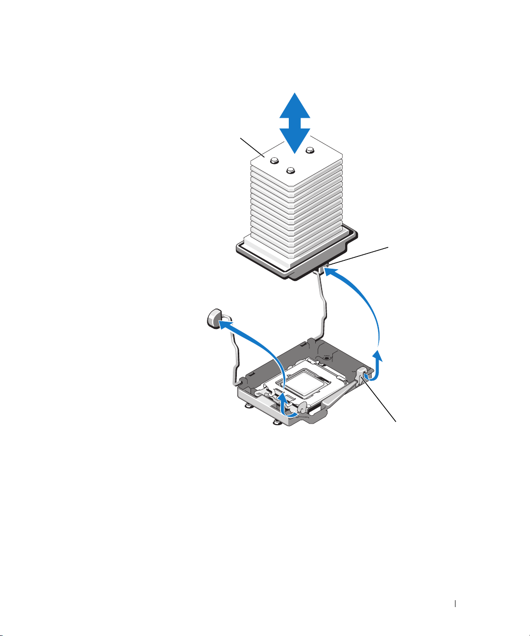
Figure 3-11. Removing and Installing the Heat Sink
1
2
3
1 heat sink 2 heat-sink retention lever (2) 3 retention lever latch
6
Wait 30 seconds for the heat sink to loosen from the processor.
7
Open the other heat sink retention lever.
8
If the heat sink does not separate from the processor, carefully rotate the heat sink in a clockwise, then
counterclockwise, direction until it releases from the processor. Do not pry the heat sink from the
processor.
9
Lift the heat sink off of the processor and set the heat sink upside down.
10
Use a clean lint-free cloth to remove any thermal grease from the surface of the processor shield.
Installing System Components 63
Page 64
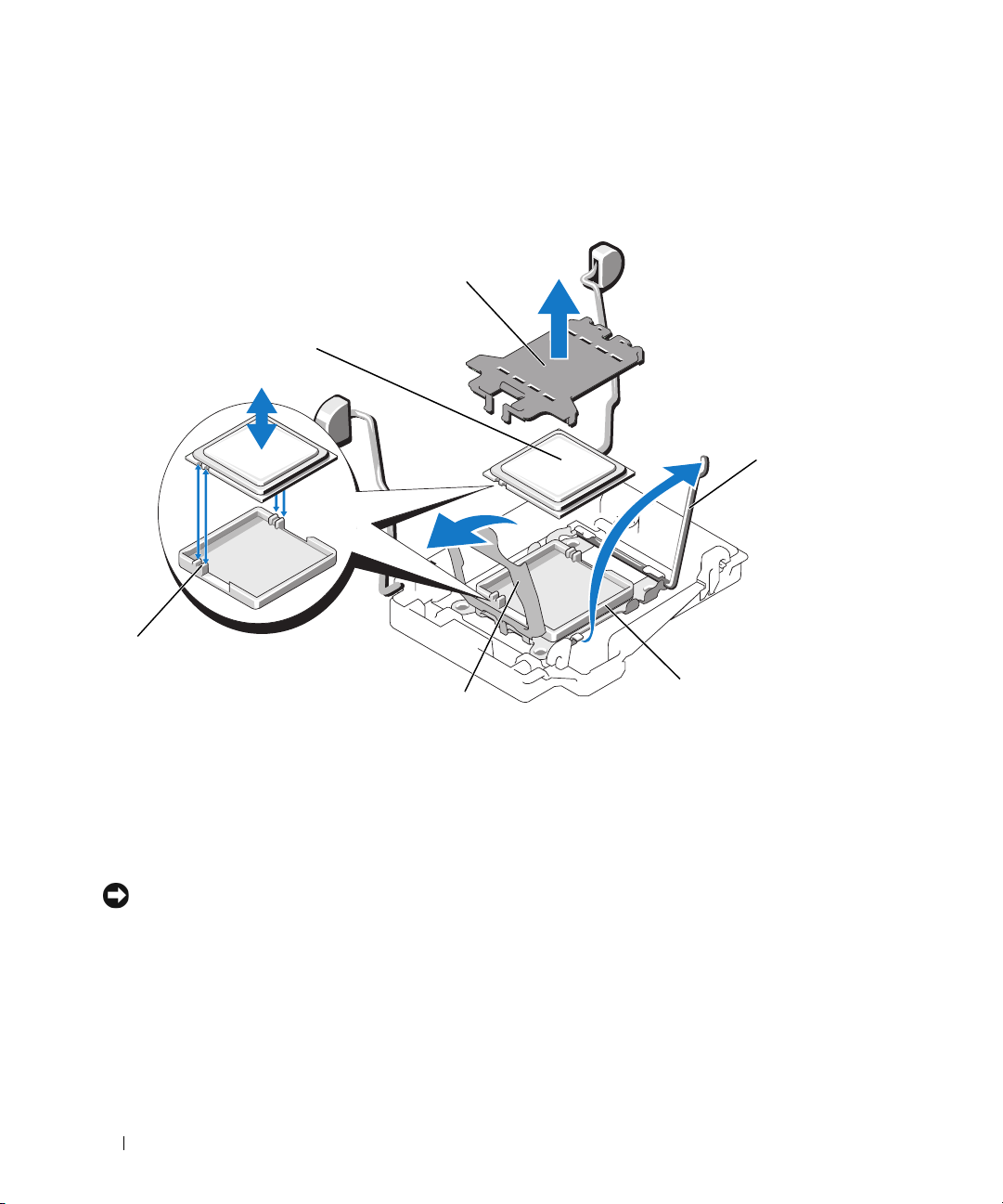
11
Pull the socket-release lever 90 degrees upward until the processor is released from the socket. See
Figure 3-12.
Figure 3-12. Removing and Installing the Processor
2
1
3
6
4
5
1 processor 2 socket cover (remove if
present before installing a
new processor)
4 socket 5 processor shield 6 socket keys (2)
12
Open the processor shield and then lift the processor out of the socket. Leave the release lever up so
3 socket-release lever
that the socket is ready for the new processor.
NOTICE: Be careful not to bend any of the pins on the socket when removing the processor. Bending the pins can
permanently damage the socket and system board.
Installing a Processor
1
Unpack the new processor.
2 Align the processor with the two
64 Installing System Components
socket keys on t
he socket
. See Figure 3-12.
Page 65

3
If you are adding a processor to an empty socket, perform the following steps:
a
Remove the protective cover from the processor socket. See Figure 3-12.
b
Pull the socket-release lever 90 degrees upward. See Figure 3-12.
c
Lift the processor shield. See Figure 3-12.
4Install the processor in the socket.
NOTICE: Positioning the processor incorrectly can permanently damage the system board or the processor when
you turn the system on.
If the release lever on the processor socket is not fully open, move it to that position.
a
b With the
NOTICE: Do not use force to seat the processor. When the processor is positioned correctly, it fits easily into the
socket.
Close the processor shield. See Figure 3-12.
c
d
R
otate the socket release lever back down until it snaps into place, securing the processor.
p
rocessor and
the
socket
keys
aligned, set the processor lightly in the socket.
Figure 3-12.
5
Install the heat sink.
NOTE: If you did not receive a replacement heat sink, use the heat sink that you removed in step 9.
If you receive a heat sink and pre-applied thermal grease with your processor kit, remove the
a
protective sheet from the thermal grease layer on top of the heat sink. See Figure 3-11.
If you did not receive a replacement heat sink with your processor kit, apply new thermal grease:
See
• Using a clean lint-free cloth, remove the existing thermal grease from the heat sink.
• Open the grease packet included with your processor kit and apply thermal grease evenly to
the top of the processor.
b Place the heat sink onto the processor. See
c Close one of the two heat sink retention levers until it locks. See
d
Close the remaining
NOTICE: If you are adding a third and fourth processor, you must also install a voltage regulator module (VRM) for
each processor. See "Installing a VRM" on page 66.
6
Replace the cooling shrouds. See "Replacing the Cooling Shrouds" on page 50.
7
Close the system. See "Closing the System" on page 47.
8
Restart the system.
heat sink retention lever.
Figure 3-11
.
Figure 3-11
.
As the system boots, it detects the presence of the new processor(s) and automatically changes the
system configuration information in the System Setup program.
Installing System Components 65
Page 66
9
Press <F2> to enter the System Setup program, and check that the processor information matches the
new system configuration.
See "Using the System Setup Program" on page 31 for instructions about using the System Setup
program.
10
Run the system diagnostics to verify that the new processor operates correctly.
See "Running the System Diagnostics" on page 117 for information about running the diagnostics.
Processor VRMs
If you add a third and fourth processor, you must also install a voltage regulator module (VRM) for each
processor.
Installing a VRM
CAUTION: Only trained service technicians are authorized to remove the system cover and access any of the
components inside the system. See your Product Information Guide for complete information about safety
precautions, working inside the computer, and protecting against electrostatic discharge.
1
Turn off the system, including any attached peripherals, and disconnect the system from the electrical
outlet.
2
Open the system. See "Opening the System" on page 46.
3
Remove the top cooling shroud. See "Removing the Cooling Shrouds" on page 49.
4
Locate the two VRM sockets. See Figure 6-2.
5
Press the ejectors on the socket down and out, as shown in Figure 3-13, to allow the VRM to be
inserted into the socket.
66 Installing System Components
Page 67
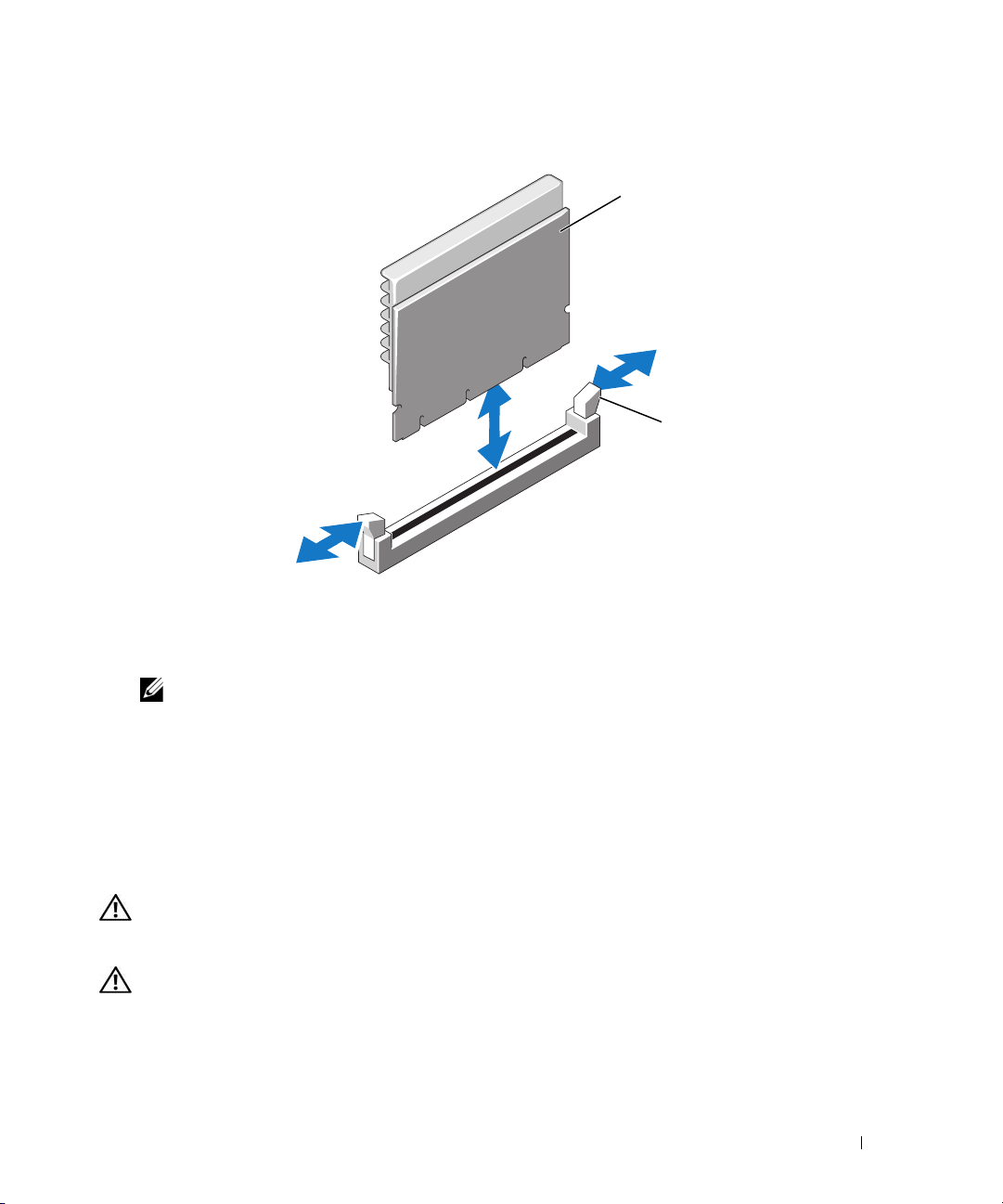
Figure 3-13. Installing and Removing a VRM
1
2
1 VRM 2 socket ejectors (2)
6
Holding the VRM by its edges, align the edge connector with the socket, and insert the VRM in the
socket.
NOTE: The VRM socket has an alignment key that allows you to install the VRM in the socket in only one way.
7
Press down on the VRM with your thumbs while pulling up on the ejectors with your index fingers to
lock the VRM into the socket.
8
Repeat step 5 through step 7 of this procedure to install the second VRM.
9
Replace the top cooling shroud. See "Replacing the Cooling Shrouds" on page 50.
10
Close the system. See "Closing the System" on page 47.
Removing a VRM
CAUTION: Only trained service technicians are authorized to remove the system cover and access any of the
components inside the system. See your Product Information Guide for complete information about safety
precautions, working inside the computer, and protecting against electrostatic discharge.
CAUTION: The VRMs are hot to the touch for some time after the system has been powered down. Allow time for
the VRMs to cool before handling them. Handle the VRMs by the card edges.
1
Turn off the system, including any attached peripherals, and disconnect the system from the electrical
outlet.
2
Open the system. See "Opening the System" on page 46.
Installing System Components 67
Page 68
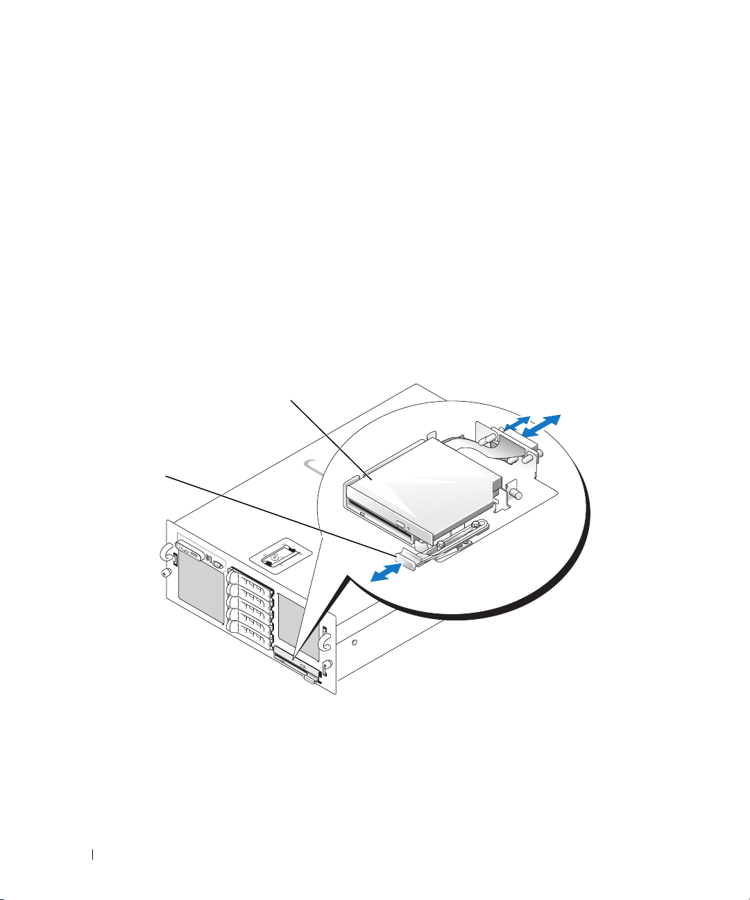
3
Remove the top cooling shroud. See "Removing the Cooling Shrouds" on page 49.
4
Locate the VRM sockets. See Figure 6-2.
5
Press down and out on the ejectors on each end of the socket and lift the VRM out of the socket. See
Figure 3-13.
Installing a Diskette Drive
1
Turn off the system, including any attached peripherals, and disconnect the system from the electrical
outlet.
2
Remove the front bezel, if attached. See"Removing and Replacing the Optional Front Bezel" on
page 45.
3
To remove the drive carrier, pull the release latch forward, then slide the carrier out of the chassis. See
Figure 3-14
Figure 3-14. Removing and Installing the Diskette/Optical Drive Carrier
.
2
1
1 release latch 2 diskette/optical drive carrier
4
Remove the optical drive or optical drive filler plate from the carrier:
a
Loosen the thumbscrew on the latch securing the optical drive or filler plate. See Figure 3-15.
b
Remove the latch.
c
Lift the optical drive or optical drive filler plate from the carrier.
68 Installing System Components
Page 69
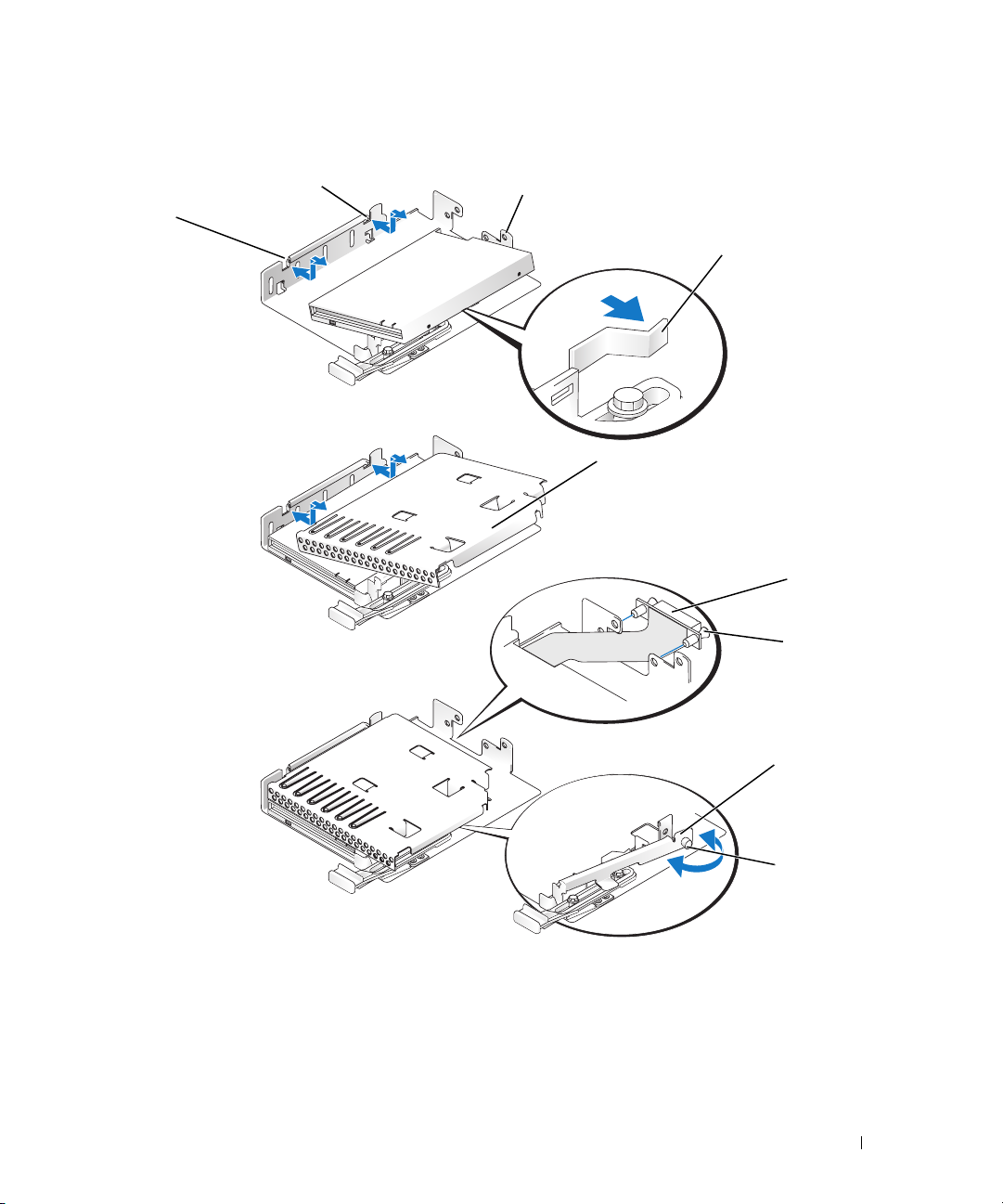
Figure 3-15. Installing a Diskette Drive in the Drive Carrier
2
1
3
4
5
6
7
1 diskette/optical drive carrier 2 alignment pins 3 diskette drive
4 retention spring 5 optical drive filler plate 6 interface board
7 plastic rivets (2) 8 latch 9 thumbscrew
Installing System Components 69
8
9
Page 70

5
To remove the diskette drive filler plate, pull the retention spring slightly away from the filler plate,
then lift the filler plate from the carrier.
6
Deflect the retention spring slightly, then insert the diskette drive into the carrier.
The pins on the carrier fit into the corresponding holes in the side of the drive. See Figure 3-15.
7
Replace the optical drive or optical drive filler plate in the carrier.
The pins on the carrier fit into the corresponding holes in the side of the drive.
8
Reinstall the latch and tighten the thumbscrew.
9
Slide in the drive carrier until the tray snaps into place. See
10
Replace the front bezel, if applicable. See "Removing and Replacing the Optional Front Bezel" on
page 45.
11
Reconnect the system and peripherals to their electrical outlets.
Figure 3-15
Installing an Optical Drive
The optional slimline optical drive is mounted on a tray that slides into the front panel and connects to
the controller on the system board through the SAS backplane.
NOTE: DVD devices are data only.
1
Turn off the system, including any attached peripherals, and disconnect the system from its electrical
outlet.
2
Remove the bezel. See "Removing and Replacing the Optional Front Bezel" on page 45.
3
To remove the drive carrier, pull the release latch forward, then slide the carrier out of the chassis. See
Figure 3-14
4
Remove the optical drive filler plate from the carrier:
a
b
c
.
Loosen the thumbscrew from the latch securing the optical drive or filler plate. See Figure 3-16.
Remove the latch.
Lift the optical drive filler plate from the carrier.
70 Installing System Components
Page 71
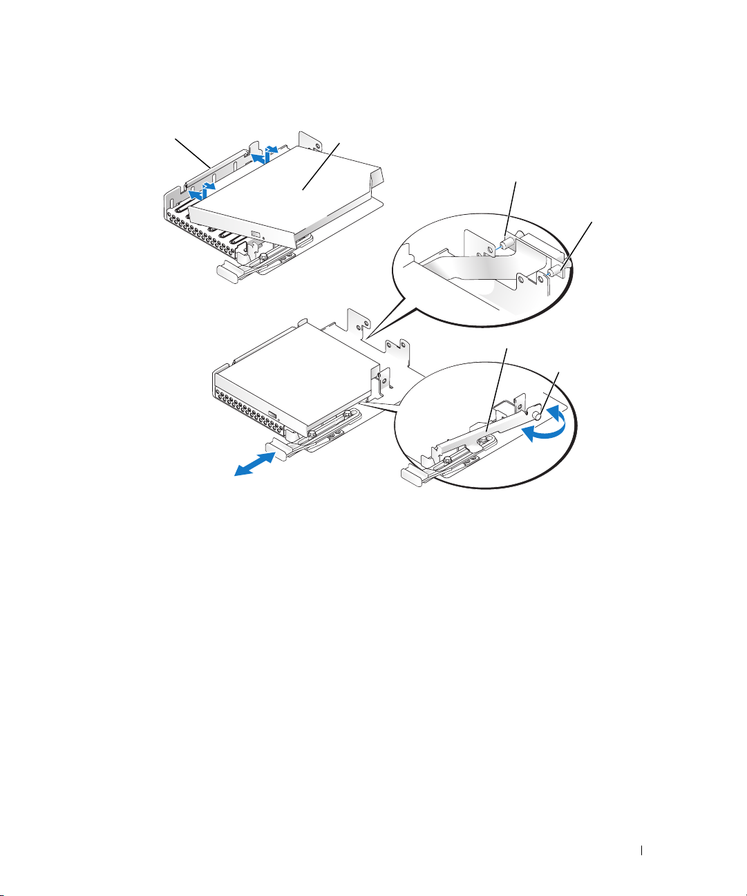
Figure 3-16. Installing an Optical Drive in the Drive Carrier
1
2
3
4
5
6
1 diskette/optical drive carrier 2 optical drive 3 interface board
4 plastic rivets (2) 5 latch 6 thumbscrew
5
Install the new optical drive in the carrier. See Figure 3-16.
The pins on the carrier fit into the corresponding holes in the side of the drive.
6
Attach the interface board to the back of the carrier, using the two plastic rivets. See Figure 3-16.
7
Reinstall the latch and tighten the thumbscrew.
8
Slide in the drive carrier until the tray snaps into place. See
Replace the front bezel, if applicable. See "Removing and Replacing the Optional Front Bezel" on
9
Figure 3-14
page 45.
10
Reconnect the system and peripherals to their electrical outlets.
Installing System Components 71
Page 72
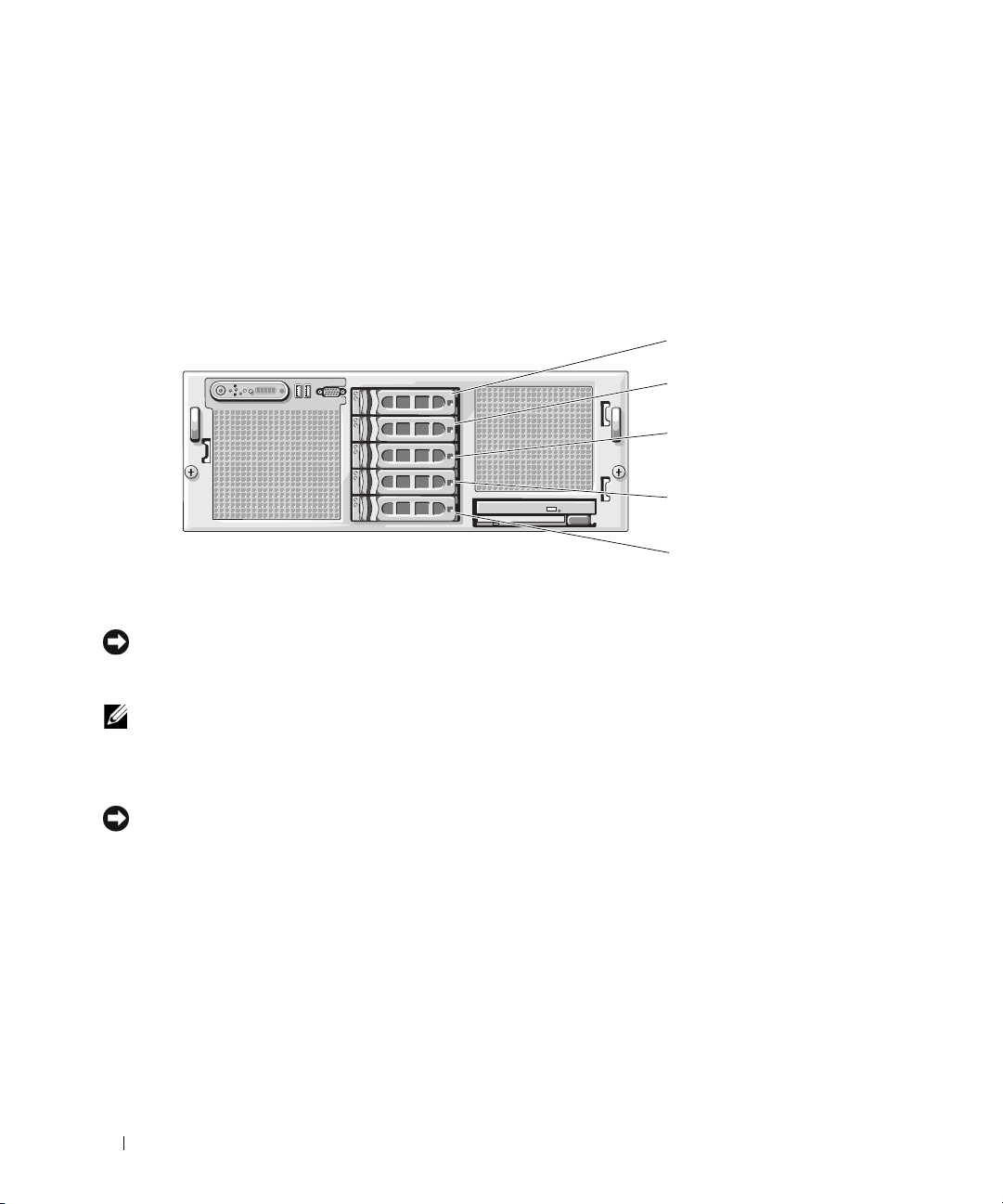
Hard Drives
Your system can accommodate up to five 3.5-inch SAS hard drives. All drives connect to the system
board through a SAS backplane board. See "SAS Backplane (Service-Only Procedure)" on page 87 for
information on these backplane options. Systems with an optional SAS RAID controller card support
hot-plug drive operation. Figure 3-17 shows the ID numbers of the drives.
Figure 3-17. Hard-Drive ID Numbers
ID 0
ID 1
ID 2
ID 3
ID 4
Before You Begin
NOTICE: Before you attempt to remove or install a drive while the system is running, see the documentation for the
optional SAS RAID controller card to ensure that the host adapter is configured correctly to support hot-plug drive
removal and insertion.
NOTE: It is recommended that you use only drives that have been tested and approved for use with the SAS
backplane board.
You may need to use different programs than those provided with the operating system to partition and
format the hard drives.
NOTICE: Do not turn off or reboot your system while the drive is being formatted. Doing so can cause a drive
failure.
When you format a high-capacity hard drive, allow enough time for the formatting to be completed.
Long format times for these drives are normal.
Configuring the Boot Device
If you plan to boot the system from a hard drive, the drive must be attached to the primary (or boot)
controller. The device that the system boots from is determined by the boot order specified in the
System Setup program.
The System Setup program provides options that the system uses to scan for installed boot devices. See
"Using the System Setup Program" on page 31 for information about the System Setup program.
72 Installing System Components
Page 73

Removing a Drive Blank
NOTICE: To maintain proper system cooling, all empty hard-drive bays must have drive blanks installed. If you
remove a hard-drive carrier from the system and do not reinstall it, you must replace the carrier with a drive blank.
1
Remove the bezel. See "Removing and Replacing the Optional Front Bezel" on page 45.
2
Insert your finger under the shrouded end of the blank and press in on the latch to eject the blank
outward from the bay.
3
Pry the ends of the blank outward until the blank is free.
Installing a Drive Blank
The drive blank is keyed to ensure correct insertion into the drive bay. To install a 3.5-inch drive blank,
insert and rotate in the keyed side of the blank into the drive bay and press evenly on the other end of the
blank until it is fully inserted and latched.
Removing a Hot-Plug Hard Drive
1
Remove the bezel. See "Removing and Replacing the Optional Front Bezel" on page 45.
2
From the RAID management software, prepare the drive for removal a
indicators on the drive carrier signal that the drive can be removed safely.
controller documentation for information about hot-plug drive removal.
If the drive has been online, the green
activity/
fault indicator will flash as the drive is powered down.
When both drive indicators are off, the drive is ready for removal.
nd wait until the hard-drive
See your SAS RAID
3 Open the drive carrier release handle to release the drive. See
Slide the hard drive out until it is free of the drive bay.
4
5
If you do not replace the hard drive, insert a drive blank in the vacated drive bay. See "Installing a Drive
Figure 3-18
.
Blank" on page 73.
NOTICE: To maintain proper system cooling, all empty hard-drive bays must have drive blanks installed.
Installing System Components 73
Page 74
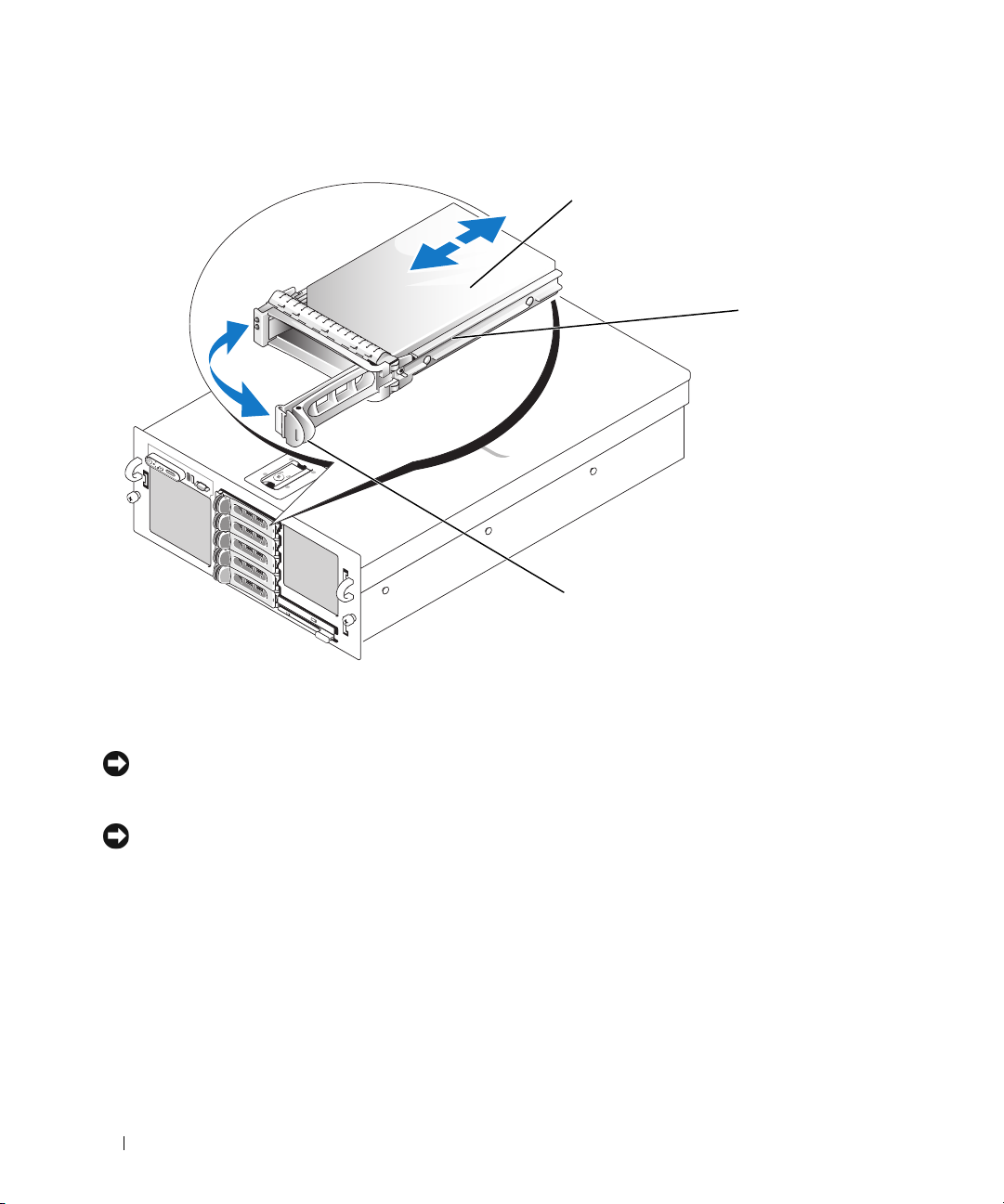
Figure 3-18. Removing and Installing a Hot-Plug Hard Drive
1
2
3
1 hard drive 2 drive carrier 3 drive carrier release handle
Installing a Hot-Plug Hard Drive
NOTICE: When installing a hard drive, ensure that the adjacent drives are fully installed. Inserting a hard-drive
carrier and attempting to lock its handle next to a partially installed carrier can damage the partially installed
carrier's shield spring and make it unusable.
NOTICE: Not all operating systems support hot-plug drive installation. See the documentation supplied with your
operating system.
1
Remove the bezel. See "Removing and Replacing the Optional Front Bezel" on page 45.
2
If a drive blank is present in the bay, remove it. See "Removing a Drive Blank" on page 73.
3
Install the hot-plug hard drive.
a
Open the handle on the hard-drive carrier.
b
Insert the hard-drive carrier into the drive bay until the carrier contacts the backplane.
c
Close the handle to lock the drive in place.
4 Replace the front bezel,
page 45.
74 Installing System Components
if applicable. See "Removing and Replacing the Optional Front Bezel" on
Page 75
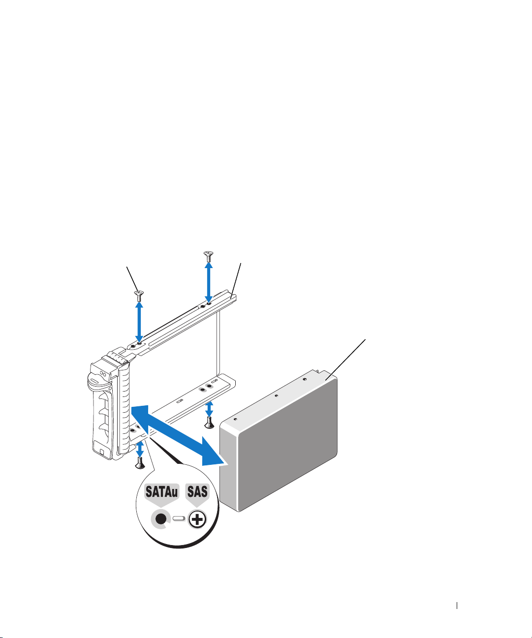
Replacing a Hard Drive in a Hard-Drive Carrier
To remove a hard drive from a drive carrier, remove the four screws from the slide rails on the hard-drive
carrier and separate the hard drive from the carrier.
To install a new hard drive in a drive carrier, perform the following steps:
1 Insert the hard drive into the hard-drive carrier with the connector end of the drive at the back. See
Figure 3-19
2 Viewing the assembly as shown in
with the hole labeled "SAS" on the hard drive carrier.
When aligned correctly, the back of the hard drive will be flush with the back of the hard-drive carrier.
.
Figure 3-19, a
lign the bottom rear screw hole on the hard drive
3 Attach the four screws to secure the hard drive to the hard-drive carrier. See
Figure 3-19. Installing a SAS Hard Drive Into a Drive Carrier
1
2
Figure 3-19
3
.
1 screws (4) 2 drive carrier 3 SAS hard drive
Installing System Components 75
Page 76
SAS Controller Cards
Removing a SAS Controller Card
CAUTION: Only trained service technicians are authorized to remove the system cover and access any of the
components inside the system. See your Product Information Guide for complete information about safety
precautions, working inside the computer, and protecting against electrostatic discharge.
1
Turn off the system, including any attached peripherals, and disconnect the system from the electrical
outlet.
2
Open the system. See "Opening the System" on page 46.
3
Disconnect the data cable(s) from the controller card.
4
If you are removing a SAS RAID controller, disconnect the RAID battery cable from the card.
5
Remove the card from the expansion slot.
See "Removing an Expansion Card" on page 55.
Installing a SAS Controller Card
CAUTION: Only trained service technicians are authorized to remove the system cover and access any of the
components inside the system. See your Product Information Guide for complete information about safety
precautions, working inside the computer, and protecting against electrostatic discharge.
1
Turn off the system, including any attached peripherals, and disconnect the system from the electrical
outlet.
2
Open the system. See "Opening the System" on page 46.
3
Install the controller card in the expansion slot labeled INTERNAL_STORAGE.
For instructions on installing the card, see "Installing an Expansion Card" on page 53.
4
Connect the card to the SAS backplane
If you are installing a SAS controller card
•
backplane. See Figure 6-3.
•
If you are installing a SAS RAID controller card
connector 0 on the card to connector SAS A on the backplane, and from connector 1 on the card
to connector SAS B on the backplane. See Figure 6-3.
, connect the SAS data cable to connector SAS A on the
, connect the SAS data cable from the blue
Installing the SAS RAID Controller Card Battery
To install the RAID battery, insert the battery into the plastic battery holder on the inner side of the
chassis, and connect the battery cable to the connector on the SAS RAID controller card next to the
RAID memory module.
76 Installing System Components
Page 77
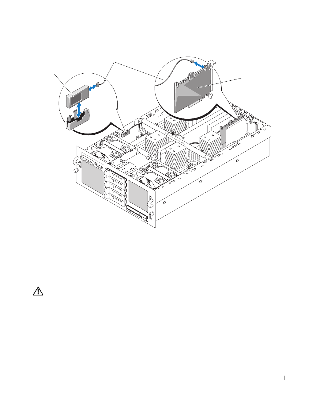
Figure 3-20. Installing the RAID Battery
2
1
1 RAID battery 2 RAID battery cable 3 RAID controller card
3
Connecting an External SAS Tape Drive
This subsection describes how to connect an external SAS tape drive to the optional external SAS
controller card.
CAUTION: Only trained service technicians are authorized to remove the system cover and access any of the
components inside the system. See your Product Information Guide for complete information about safety
precautions, working inside the computer, and protecting against electrostatic discharge.
1
Turn off the system, including any attached peripherals, and disconnect the system from the electrical
outlet.
2
Open the system. See "Opening the System" on page 46.
3
Ground yourself by touching an unpainted metal surface on the back of the system and unpack the
drive.
4
Unpack the tape drive and controller card.
Installing System Components 77
Page 78
5
Install the external SAS controller card in an expansion slot. See "Installing an Expansion Card" on
page 53.
6
Connect the tape drive’s interface cable to the drive.
7
Connect the other end of the interface cable to the external SAS connector on the controller card
bracket.
8
Connect the tape drive's power cable to an electrical outlet.
9
Close the system. See "Closing the System" on page 47.
10
Reconnect the system and peripherals to their electrical outlets, and turn them on.
11
Perform a tape backup and verification test with the drive as instructed in the software documentation
that came with the drive.
Connecting an External Fibre Channel Storage Device
This subsection describes how to connect external Fibre Channel devices to an optional Fibre Channel
HBA card.
CAUTION: Only trained service technicians are authorized to remove the system cover and access any of the
components inside the system. See your Product Information Guide for complete information about safety
precautions, working inside the computer, and protecting against electrostatic discharge.
1
Turn off the system, including any attached peripherals, and disconnect the system from the electrical
outlet.
2
Open the system. See "Opening the System" on page 46.
3
Ground yourself by touching an unpainted metal surface on the back of the system, unpack the drive,
and compare the jumper and switch settings with those in the documentation that came with the
drive.
4
Install the Fibre Channel HBA in an expansion slot. See "Installing an Expansion Card" on page 53.
5
Connect the end of the Fibre Channel cable to the connector on the HBA card bracket.
6
Close the system. See "Closing the System" on page 47.
7
Reconnect the system and peripherals to their electrical outlets, and turn them on.
System Battery
The system battery is a 3.0-volt (V), coin-cell battery.
Replacing the System Battery
CAUTION: Only trained service technicians are authorized to remove the system cover and access any of the
components inside the system. See your Product Information Guide for complete information about safety
precautions, working inside the computer, and protecting against electrostatic discharge.
78 Installing System Components
Page 79
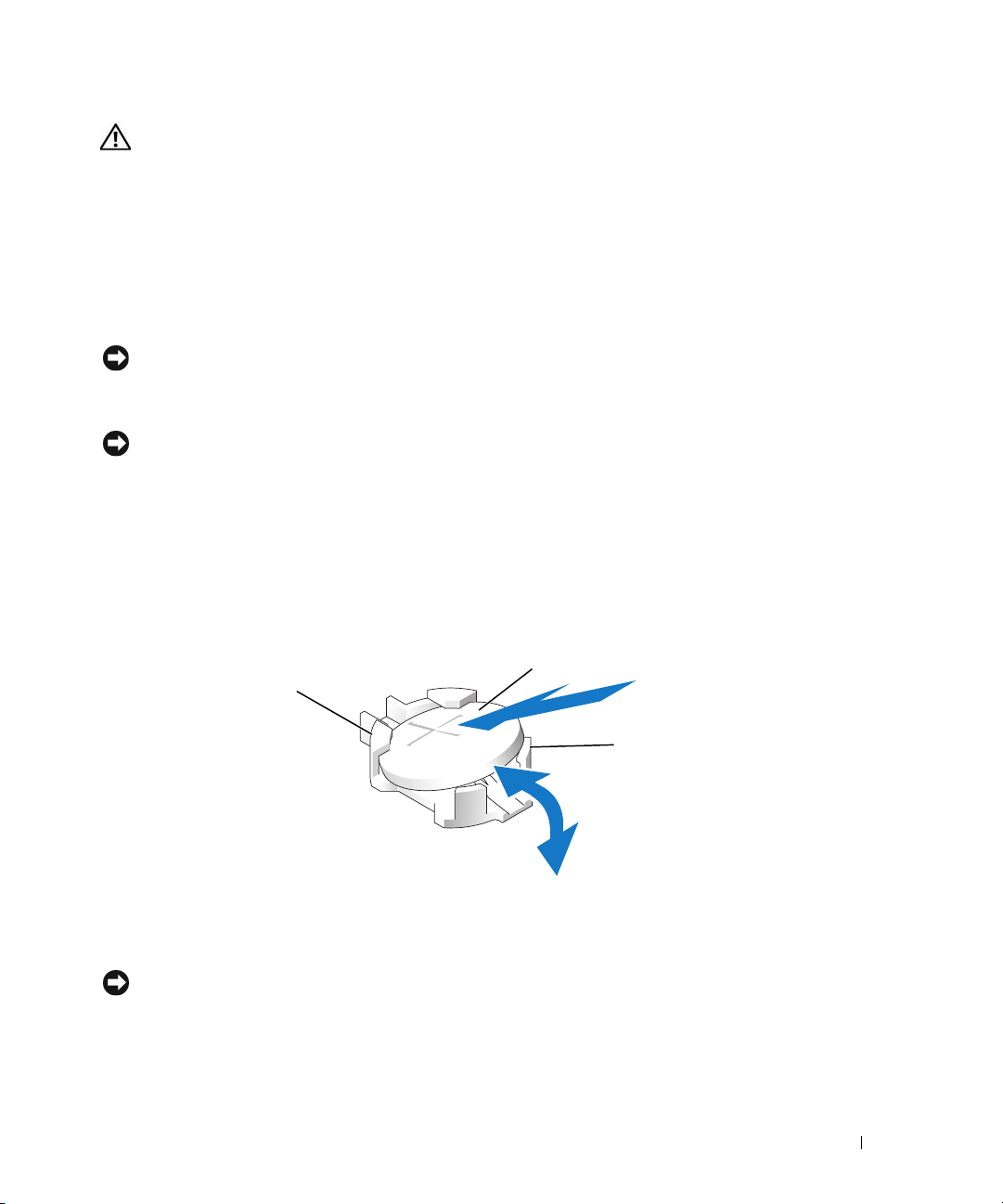
CAUTION: There is a danger of a new battery exploding if it is incorrectly installed. Replace the battery only
with the same or equivalent type recommended by the manufacturer. Discard used batteries according to the
manufacturer's instructions. See your System Information Guide for additional information.
1
Turn off the system, including any attached peripherals, and disconnect the system from the electrical
outlet.
2
Open the system. See "Opening the System" on page 46.
3
Remove the cooling shrouds. See "Removing the Cooling Shrouds" on page 49.
4
Locate the battery socket. See Figure 6-2.
NOTICE: If you pry the battery out of its socket with a blunt object, be careful not to touch the system board with
the object. Ensure that the object is inserted between the battery and the socket before you attempt to pry out the
battery. Otherwise, you may damage the system board by prying off the socket or by breaking circuit traces on the
system board.
NOTICE: To avoid damage to the battery connector, you must firmly support the connector while installing or
removing a battery.
5
Remove the system battery. See Figure 3-21.
a
Support the battery connector by pressing down firmly on the positive side of the connector.
b
While supporting the battery connector, press the battery toward the positive side of the
connector and pry it up out of the securing tabs at the negative side of the connector.
Figure 3-21. Replacing the System Battery
2
1
3
1 positive side of battery
connector
NOTICE: To avoid damage to the battery connector, you must firmly support the connector while installing or
removing a battery.
2 system battery 3 negative side of battery
connector
Installing System Components 79
Page 80
6
Install the new system battery.
a
Support the battery connector by pressing down firmly on the positive side of the connector.
b
Hold the battery with the "+" facing up, and slide it under the securing tabs at the positive side of
the connector.
c
Press the battery straight down into the connector until it snaps into place.
7
Replace the cooling shrouds. See "Replacing the Cooling Shrouds" on page 50.
8
Close the system. See "Closing the System" on page 47.
9
Reconnect the system to its electrical outlet and turn the system on, including any attached peripherals.
10
Enter the System Setup program to confirm that the battery is operating properly. See "Using the
System Setup Program" on page 31.
11
Enter the correct time and date in the System Setup program's
12
Exit the System Setup program.
13
To test the newly installed battery, turn off the system and disconnect it from the electrical outlet for
Time
and
Date
fields.
at least an hour.
14
After an hour, reconnect the system to its electrical outlet and turn it on.
15
Enter the System Setup program and if the time and date are still incorrect, see "Getting Help" on
page 129 for instructions on obtaining technical assistance.
Control Panel Assembly (Service-Only Procedure)
Removing the Control Panel
CAUTION: Only trained service technicians are authorized to remove the system cover and access any of the
components inside the system. See your Product Information Guide for complete information about safety
precautions, working inside the computer, and protecting against electrostatic discharge.
1
Turn off the system and attached peripherals, and disconnect the system from the electrical outlet.
2
Open the system. See "Opening the System" on page 46.
3 Disconnect the control panel data cable from the control panel board.
4 Disconnect the display module cable from the control panel board.
5
Remove the three Torx screws securing the control panel board to the system chassis and remove the
board.
6
Remove the display module:
a
Insert the end of a paper clip into the hole on the right side of the display module and gently pry
the label off.
b
Remove the two Torx screws that secure the display module to the system chassis.
7
Remove the display module from the chassis cutout.
80 Installing System Components
See Figure 3-22.
See Figure 3-22.
Page 81
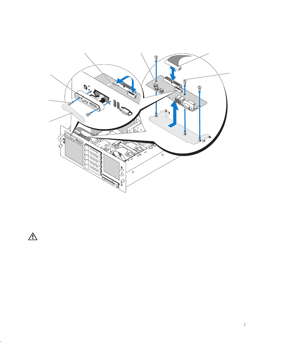
Figure 3-22. Removing and Installing the Control Panel
2
3
4
1
7
6
3
1 display module 2 display module cable 3 control panel board
4 control panel board cable 5 control panel board screws (3) 6 display module label
7 display module screws (2)
5
Installing the Control Panel
CAUTION: Only trained service technicians are authorized to remove the system cover and access any of the
components inside the system. See your Product Information Guide for complete information about safety
precautions, working inside the computer, and protecting against electrostatic discharge.
1
Insert the control panel assembly display module into the chassis cutout and secure it with the two
Torx screws.
2
Affix the control panel label to the display module.
3 Install the control panel board in the system chassis and secure with the three Torx screws. See
Figure 3-22
4 Connect the display module cable to the control panel board. See
Connect the control panel cable to the control panel board and secure the cable in the cable guides on
5
the chassis.
.
Figure 3-22
Installing System Components 81
.
Page 82
6
Close the system. See "Closing the System" on page 47.
7
Replace the front bezel, if applicable. See "Removing and Replacing the Optional Front Bezel" on
page 45.
8
Reconnect the system to the power source and turn on the system and attached peripherals.
Fan Interposer Board (Service-Only Procedure)
Removing a Fan Interposer Board
CAUTION: Only trained service technicians are authorized to remove the system cover and access any of the
components inside the system. See your Product Information Guide for complete information about safety
precautions, working inside the computer, and protecting against electrostatic discharge.
1
Turn off the system and attached peripherals, and disconnect the system from the electrical outlet.
2
Open the system. See "Opening the System" on page 46.
NOTICE: To prevent damage to the drives and backplane, you must remove the SAS drives and diskette/optical
drive carrier from the system before removing the backplane. You must note the number of each hard drive and
temporarily label them before removal so that you can replace them in the same locations.
3
To remove the optical/diskette drive carrier, pull the release latch forward, then slide the carrier out of
the chassis. See Figure 3-18.
4
Remove fans 1 and 3 or 2 and 4 (depending on which fan interposer board is being replaced). See
"Removing a Cooling Fan" on page 48.
5
Remove the SAS backplane. See "SAS Backplane (Service-Only Procedure)" on page 87.
6
Remove the two screws and remove the fan interposer board. See Figure 3-23.
82 Installing System Components
Page 83
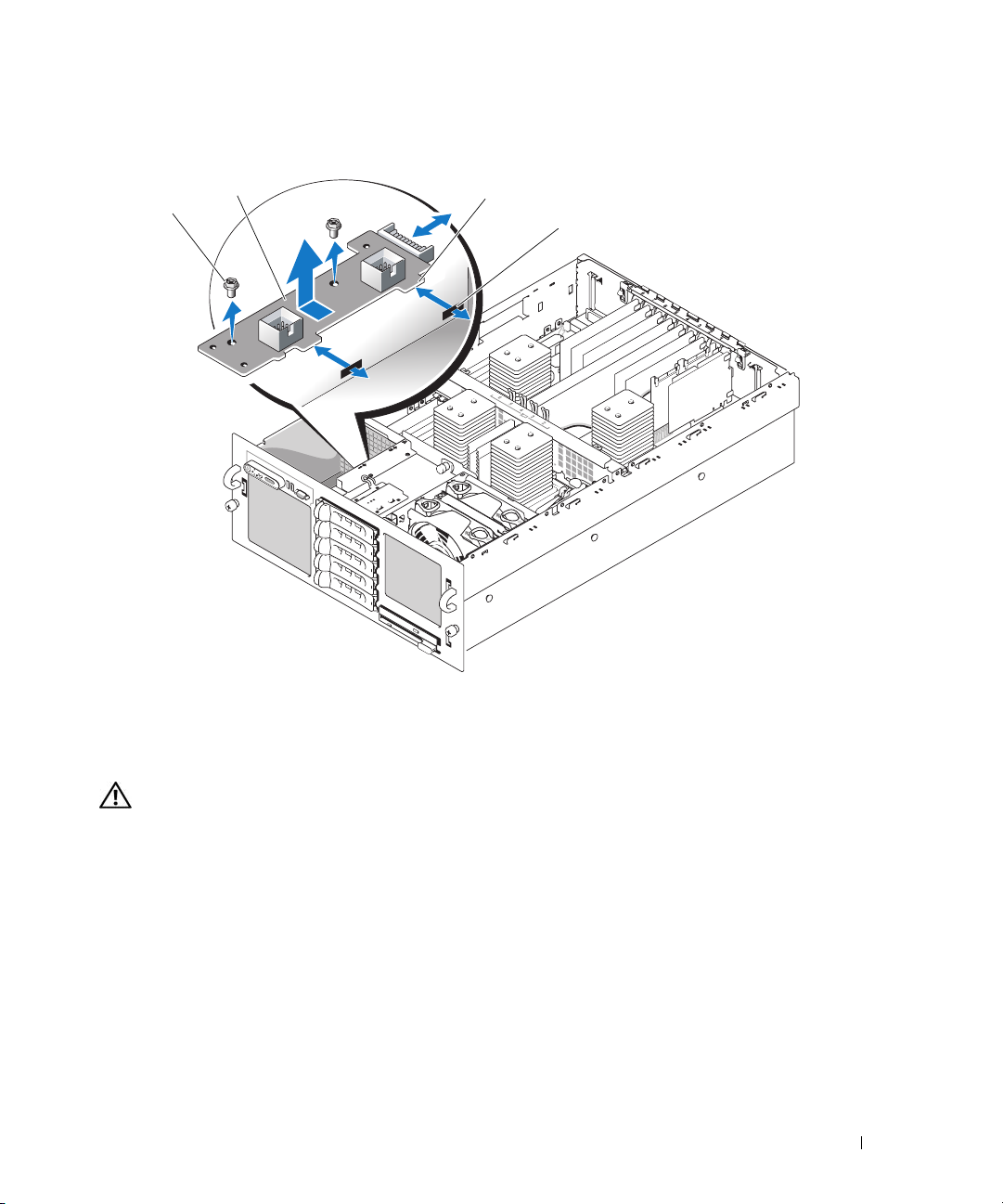
Figure 3-23. Removing and Installing a Fan Interposer Board
2
1
1 screws (2) 2 fan interposer board 3 securing tabs (2)
4 slots (2)
3
4
Installing a Fan Interposer Board
CAUTION: Only trained service technicians are authorized to remove the system cover and access any of the
components inside the system. See your Product Information Guide for complete information about safety
precautions, working inside the computer, and protecting against electrostatic discharge.
1
Slip the two securing tabs on the fan interposer board into the two slots on the side of the fan bay. See
Figure 3-23.
2
Secure the fan interposer board with the two screws.
3
Reinstall the SAS backplane. See "Installing the SAS Backplane" on page 89.
4
Install the fans. See "Replacing a Cooling Fan" on page 49.
5
Install the optical drive/diskette drive carrier.
Slide the drive carrier into its drive bay and press in the release latch. See
Figure 3-14
Installing System Components 83
.
Page 84
6
Install the SAS hard drives in their original locations. See "Installing a Hot-Plug Hard Drive" on
page 74.
7
Close the system. See "Closing the System" on page 47.
8
Reconnect the system to its electrical outlet and turn the system on, including any attached
peripherals.
Power Distribution Board (Service-Only Procedure)
Removing the Power Distribution Board
CAUTION: Only trained service technicians are authorized to remove the system cover and access any of the
components inside the system. See your Product Information Guide for complete information about safety
precautions, working inside the computer, and protecting against electrostatic discharge.
1
Turn off the system and attached peripherals, and disconnect the system from the electrical outlet.
2
Open the system. See "Opening the System" on page 46.
3
Remove the power supplies. See "Removing a Power Supply" on page 51.
4
Remove the system board. See "Removing the System Board" on page 89.
5
Remove the seven screws. securing the board. See Figure 3-24.
6
Lift the power distribution board out of the chassis.
84 Installing System Components
Page 85
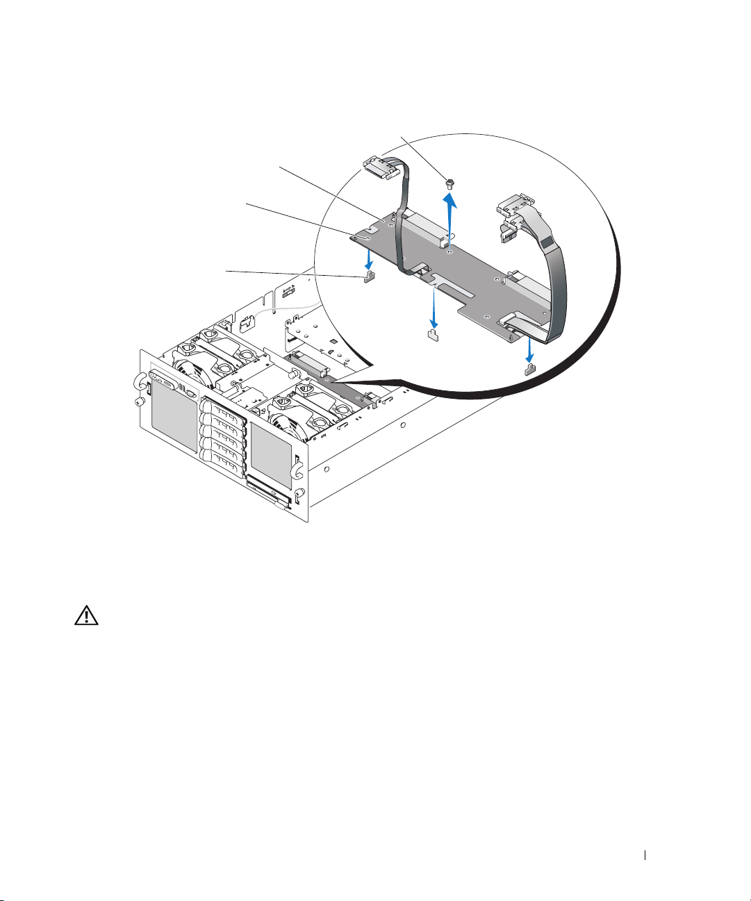
Figure 3-24. Removing and Installing the Power Distribution Board
4
3
2
1
1 retention tabs (3) 2 retention slots (3) 3 power distribution board
4 screws (7)
Installing the Power Distribution Board
CAUTION: Only trained service technicians are authorized to remove the system cover and access any of the
components inside the system. See your Product Information Guide for complete information about safety
precautions, working inside the computer, and protecting against electrostatic discharge.
1
Position the three retention slots on the power distribution board with the three retention tabs on the
bottom of the chassis. See Figure 3-24.
2
Secure the power distribution board with the seven screws.
3
Install the system board. See step 3 through step 14 in "Installing the System Board."
4
Install the power supplies. See "Replacing a Power Supply" on page 52.
5
Close the system. See "Closing the System" on page 47.
6
Reconnect the system to its electrical outlet and turn the system on, including any attached
peripherals.
Installing System Components 85
Page 86
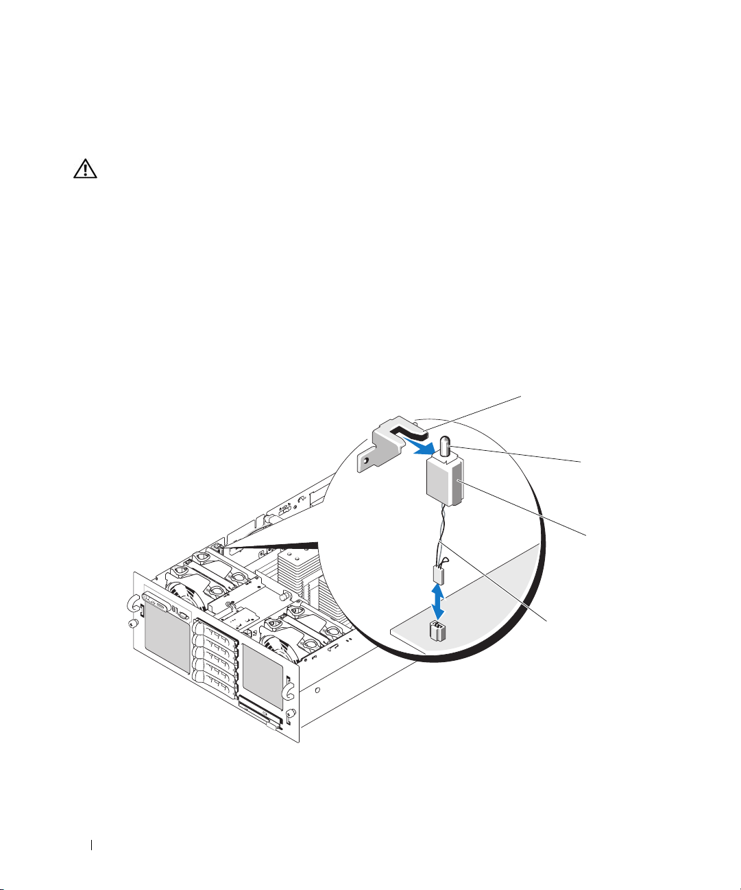
Chassis Intrusion Switch (Service-Only Procedure)
Removing the Chassis Intrusion Switch
CAUTION: Only trained service technicians are authorized to remove the system cover and access any of the
components inside the system. See your Product Information Guide for complete information about safety
precautions, working inside the computer, and protecting against electrostatic discharge.
1
Turn off the system and attached peripherals, and disconnect the system from the electrical outlet.
2
Open the system. See "Opening the System" on page 46.
3
Remove the top cooling shroud. See "Removing the Cooling Shrouds" on page 49.
4
If present, remove the heat sink from processor 4. See "Processors" on page 62.
5
Disconnect the intrusion-switch cable from its system board connector. See Figure 3-25.
6
Grasp the intrusion switch and slowly and firmly pull the switch out from the intrusion-switch clip.
Figure 3-25. Removing and Installing the Chassis Intrusion Switch
1
2
1 intrusion-switch clip 2 intrusion switch 3 grooved side (2)
4 intrusion-switch cable
86 Installing System Components
3
4
Page 87
Installing the Chassis Intrusion Switch
CAUTION: Only trained service technicians are authorized to remove the system cover and access any of the
components inside the system. See your Product Information Guide for complete information about safety
precautions, working inside the computer, and protecting against electrostatic discharge.
1
Connect the intrusion-switch cable to its system board connector. See Figure 3-25.
2
Align the two grooved sides of the top of the intrusion switch with the inside of the intrusion-switch
clip and then gently, but firmly, press in the switch until it is fully seated. See Figure 3-25.
3
If applicable, reinstall the heat sink onto processor 4. See "Processors" on page 62.
4
Replace the top cooling shroud. See "Replacing the Cooling Shrouds" on page 50.
5
Close the system. See "Closing the System" on page 47.
6
Reconnect the system to its electrical outlet and turn the system on, including any attached
peripherals.
SAS Backplane (Service-Only Procedure)
Removing the SAS Backplane
CAUTION: Only trained service technicians are authorized to remove the system cover and access any of the
components inside the system. See your Product Information Guide for complete information about safety
precautions, working inside the computer, and protecting against electrostatic discharge.
1
If applicable, remove the bezel. See "Removing and Replacing the Optional Front Bezel" on page 45.
2
Turn off the system and attached peripherals, and disconnect the system from the electrical outlet.
3
Open the system. See "Opening the System" on page 46.
NOTICE: To prevent damage to the drives and backplane, you must remove the SAS drives and diskette/optical
drive carrier from the system before removing the backplane.
NOTICE: You must note the number of each hard drive and temporarily label them before removal so that you can
replace them in the same locations.
4
Remove all SAS hard drives. See "Removing a Hot-Plug Hard Drive" on page 73.
5
To remove the optical/diskette drive carrier, pull the release latch forward, then slide the carrier out of
the chassis. See Figure 3-18.
6
Remove the cooling shrouds. See "Removing the Cooling Shrouds" on page 49.
NOTICE: When disconnecting the control-panel cable, hold the white pull-tab next to the control-panel cable
connector to prevent damage to the SAS backplane or the cable itself.
7
Disconnect the control-panel cable from the control-panel cable connector on the front of the SAS
backplane. See Figure 6-3.
8
Disconnect the SAS, interface, and power cables from the back of the SAS backplane.
Installing System Components 87
Page 88
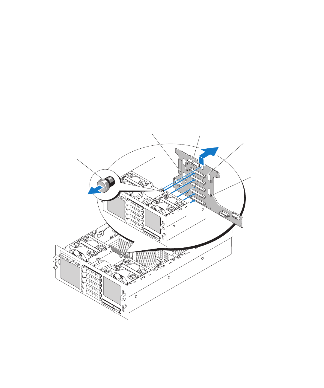
9
Remove the SAS backplane:
a
Pull the spring-loaded blue retention pin away from the front of the backplane, then slide the
backplane upward. See Figure 3-26.
b
When the backplane cannot slide upward any farther, pull the backplane toward the back of the
system to remove it from the retention hooks.
c
Lift the board out of the system, being careful to avoid damaging components on the face of the
board.
d
Place the SAS backplane face down on a work surface.
Figure 3-26. Removing and Installing the SAS Backplane
2
1
3
4
5
1 retention pin 2 SAS backplane 3 control-panel cable connector
4 installation alignment slot 5 retention slots (7)
88 Installing System Components
Page 89
Installing the SAS Backplane
CAUTION: Only trained service technicians are authorized to remove the system cover and access any of the
components inside the system. See your Product Information Guide for complete information about safety
precautions, working inside the computer, and protecting against electrostatic discharge.
1
Install the SAS backplane:
a
Slowly lower the backplane into the system, being careful to avoid damaging components on the
face of the board.
b
Align the installation alignment slot on the bottom of the backplane with the alignment pin on
the bottom of the chassis. See Figure 3-26.
c
Slide the retention slots on the backplane over the retention hooks on the chassis.
d
Slide the backplane downward until the blue retention pin snaps into place.
2
Connect the SAS, interface, and power cables to the back of the SAS backplane.
3
Connect the control-panel cable to the front of the SAS backplane.
4
Install the SAS hard drives in their original locations. See "Hard Drives" on page 72.
5
Install the optical drive/diskette drive carrier.
Slide the drive carrier into its drive bay and press in the release latch. See
6
Install the cooling shrouds. See "Replacing the Cooling Shrouds" on page 50.
7
Close the system. See "Closing the System" on page 47.
8
Reconnect the system to its electrical outlet and turn the system on, including any attached
peripherals.
Figure 3-14
.
System Board (Service-Only Procedure)
Removing the System Board
CAUTION: Only trained service technicians are authorized to remove the system cover and access any of the
components inside the system. See your Product Information Guide for complete information about safety
precautions, working inside the computer, and protecting against electrostatic discharge.
1
Turn off the system and attached peripherals, and disconnect the system from the electrical outlet.
2
Open the system. See "Opening the System" on page 46.
NOTICE: To prevent damage to the drives and backplane, you must remove the SAS drives and diskette/optical
drive carrier from the system before removing the backplane.
NOTICE: Note the number of each hard drive and temporarily label them before removal so that you can replace
them in the same locations.
3
Remove the cooling shrouds. See "Removing the Cooling Shrouds" on page 49.
4
Remove the processor heat sinks. See "Processors" on page 62.
Installing System Components 89
Page 90
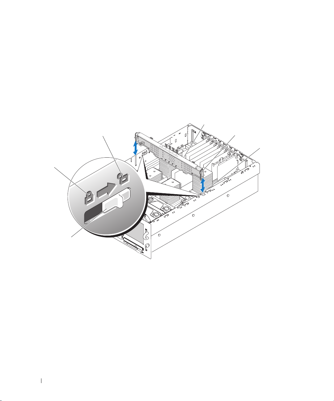
5
Disconnect the SAS, interface, and power cables from the back of the SAS backplane.
6
Remove all expansion cards and the controller card. See "Removing an Expansion Card" on page 55.
7
If present, disconnect and remove the RAC card.
8
If present, remove the VRMs for processors 3 and 4. See "Removing a VRM" on page 67.
9
Place the two slide switches on each side of the chassis in the unlocked position to release the chassis
crossbar, then lift up the crossbar and remove it. See Figure 3-27.
Figure 3-27. Removing and Installing the Chassis Crossbar
3
2
1
6
1 locked position 2 unlocked position 3 crossbar
4 guides (2) 5 slots (2) 6 slide switches (2)
10
Disconnect all data interface cables, the chassis intrusion switch cable, and the RAID battery cable (if
4
5
applicable) from the system board.
11
Disconnect the power distribution cable harness from the system board.
The power distribution cable harness and the side of the chassis have Velcro pads to hold the cable
harness in place while you remove the system board. Bend the cable harness straight up and secure it to
the side of the chassis. See Figure 3-28.
90 Installing System Components
Page 91
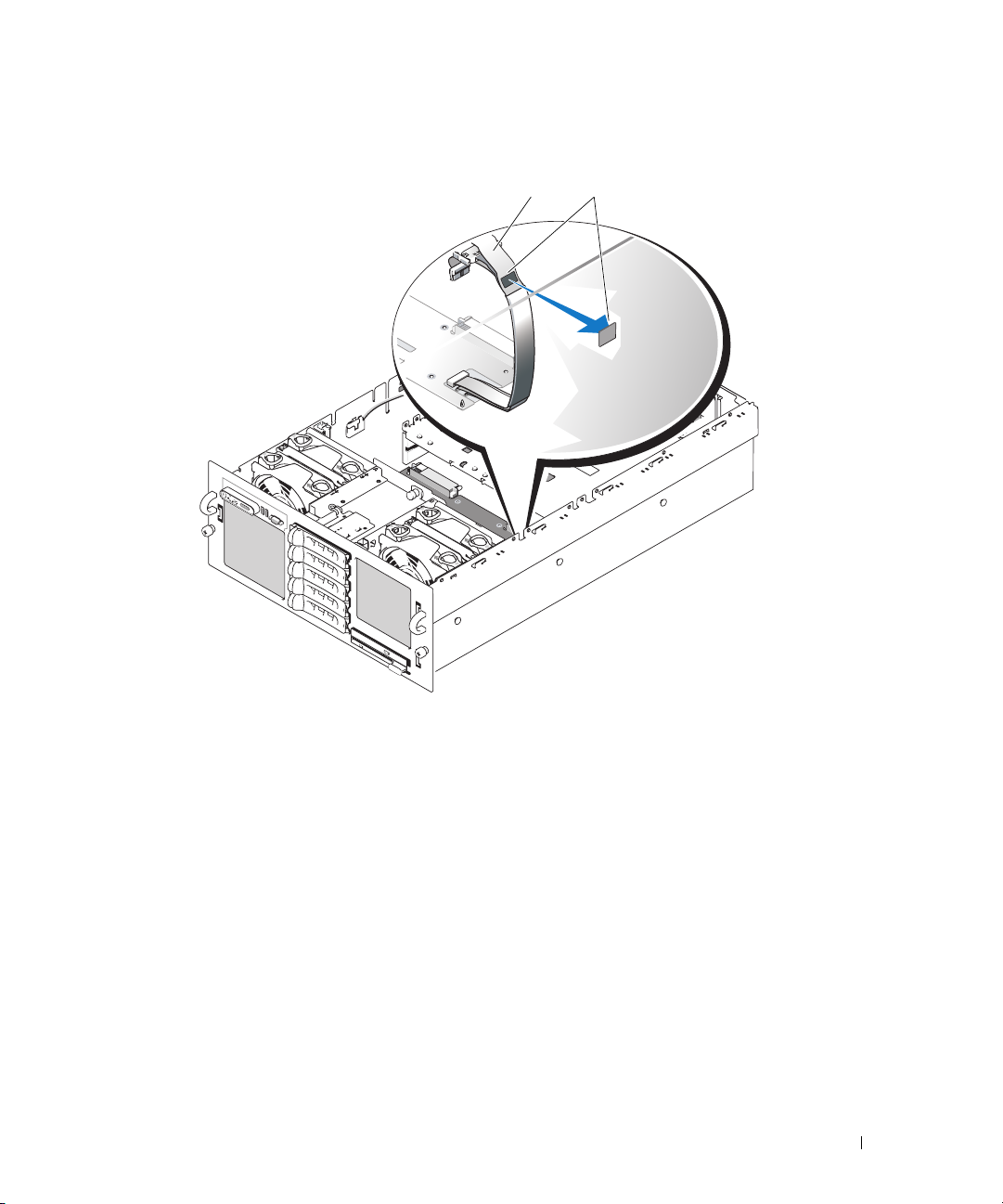
Figure 3-28. Securing the Power Distribution Cable Harness
1 power distribution cable
harness
1
2 Velcro pads (2)
2
12
Remove the RAID battery compartment:
a
Lift the snap lever and gently pull the RAID battery compartment straight up. See Figure 3-29.
b
Lift the battery compartment away from the side of the chassis.
Installing System Components 91
Page 92
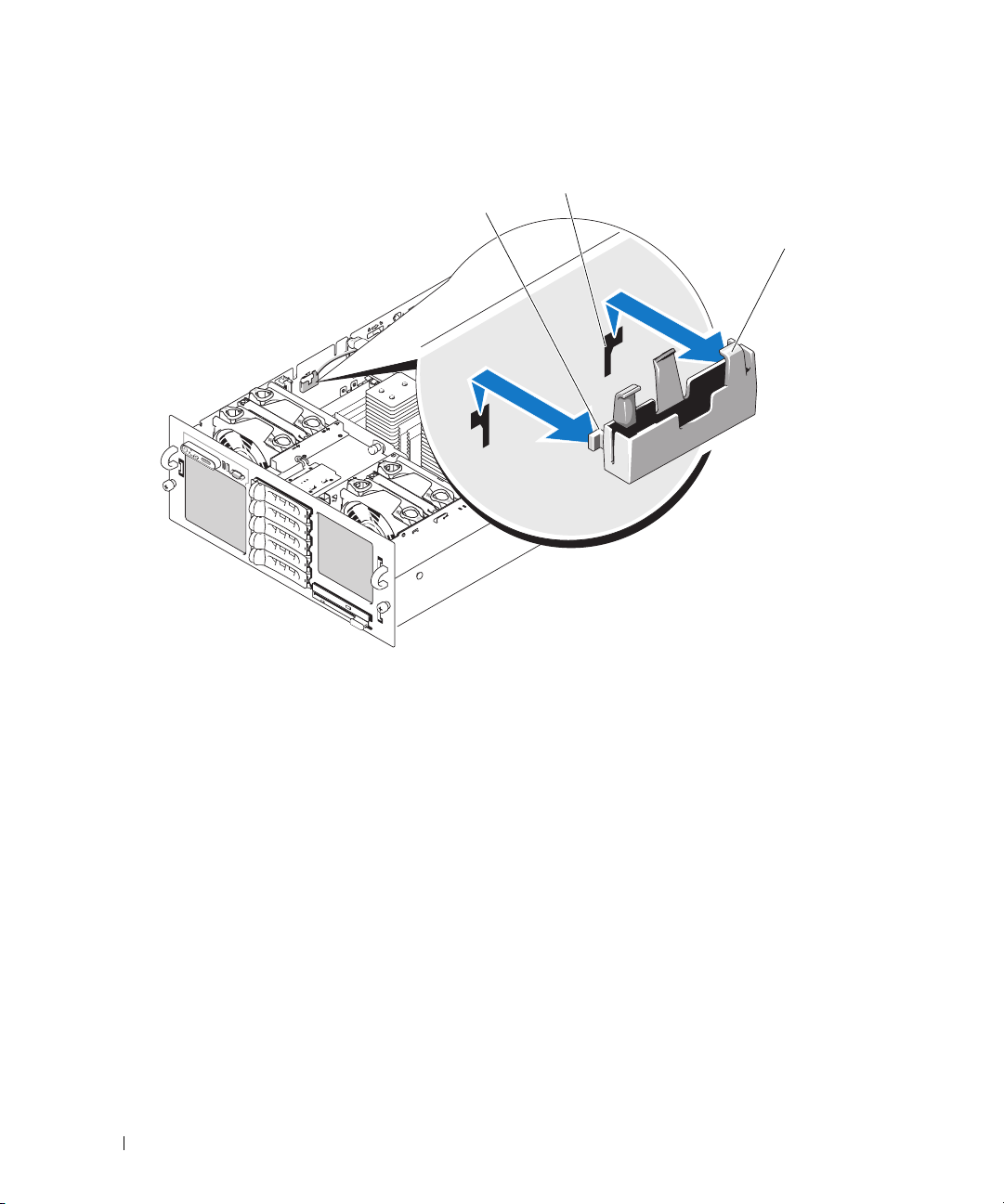
Figure 3-29. Removing and Installing the RAID Battery Compartment
2
1
1 securing tabs (2) 2 securing slots (2) 3 RAID battery compartment
3
13
Remove the system board:
a
Pull up the spring-loaded blue retention pin located in the center of the system board, and then
slide the system board toward the front of the chassis until it stops. See Figure 3-30.
b
Slowly and evenly lift the system board above the retention hooks, ensuring that the system board
is clear of all retention hooks, then evenly lift up the left side of the system board. See Figure 3-30.
c
Lift the system board out of the chassis, left side first.
92 Installing System Components
Page 93
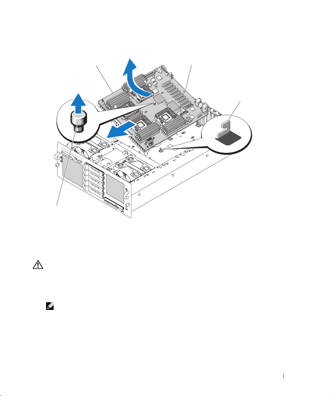
Figure 3-30. Removing and Installing the System Board
1
4
1 system board 2 retention slots 3 retention hooks
4 retention pin
2
3
Installing the System Board
CAUTION: Only trained service technicians are authorized to remove the system cover and access any of the
components inside the system. See your Product Information Guide for complete information about safety
precautions, working inside the computer, and protecting against electrostatic discharge.
1
Transfer the processors to the new system board. See Figure 6-2 for the location of the system board
connectors.
NOTE: Do not install the heat sinks at this time.
2
Remove the memory modules and transfer them to the same locations on the new board. See
"Removing Memory Modules" on page 61 and "Installing Memory Modules" on page 60.
3
Install the new system board:
a
Lower the right side of the system board into the chassis.
b
Slowly lower the left side of the system board into the chassis.
Installing System Components 93
Page 94

NOTE: Ensure that the SAS backplane power cable from the power distribution board does not impede the
system board as you lower the system board into the chassis.
c
Slightly lift up the front of the system board and maneuver the system board to the bottom of the
chassis until it lays completely flat.
d
Ensure that all retention hooks on the bottom of the chassis are inserted into the retention slots on
the system board. See Figure 3-30.
e
Push the system board toward the back of the chassis until the blue retention pin snaps into place.
4
Install the RAID battery compartment:
a
Insert the two securing tabs on the battery compartment into the two securing slots on the side of
the chassis. See Figure 3-29.
b
Press down the battery compartment to secure it.
5
Connect the cables in the order listed below (see Figure 6-2 and Figure 6-3 for the locations of the
connectors on the system board and on the SAS backplane):
• Power distribution harness to the power connectors on the corner of the system board
• Interface cable from the system board CONTROL_PANEL connector to the SAS backplane
interface connector
• SAS A data cable from controller card connector 0 connector to the SAS A backplane connector
• SAS B data cable from controller card connector 1 to the SAS B backplane connector, if applicable
• SAS power cable to the SAS backplane power connector
• Chassis intrusion switch cable to the system board intrusion switch connector
6
Install the processor heat sinks. See "Processors" on page 62.
7
If applicable, reinstall the two processor VRMs. See "Installing a VRM" on page 66.
8
Install the chassis crossbar:
a
Insert the guides on each end of the crossbar into the slots on each side of the chassis. See
Figure 3-27.
b
Slide the crossbar down until the guides are at the bottom of the slots.
c
Secure the crossbar by sliding the two slide switches on each side of the chassis to the locked
position.
9
Install all expansion cards. See "Installing an Expansion Card" on page 53.
10
If applicable, reconnect the RAID battery cable to the RAID controller card.
11
If applicable, reinstall and connect the RAC card.
12
Install the cooling shrouds. See "Replacing the Cooling Shrouds" on page 50.
13
Install the optical drive/diskette drive carrier.
Slide the drive carrier into its drive bay and press in the release latch. See
Figure 3-14
.
94 Installing System Components
Page 95

14
Install the SAS hard drives in their original locations. See "Installing a Hot-Plug Hard Drive" on
page 74.
15
Close the system. See "Closing the System" on page 47.
16
Reconnect the system to its electrical outlet and turn the system on, including any attached
peripherals.
17
Replace the bezel. See "Removing and Replacing the Optional Front Bezel" on page 45.
Installing System Components 95
Page 96

96 Installing System Components
Page 97
Troubleshooting Your System
Safety First—For You and Your System
To perform certain procedures in this document, you must remove the system cover and work inside
the system. While working inside the system, do not attempt to service the system except as
explained in this guide and elsewhere in your system documentation.
CAUTION: Only trained service technicians are authorized to remove the system cover and access any of
the components inside the system. Before performing any procedure, see your Product Information Guide for
complete information about safety precautions, working inside the computer and protecting against
electrostatic discharge.
Start-Up Routine
Look and listen during the system's start-up routine for the indications described in Table 4-1.
Table 4-1. Start-Up Routine Indications
Look/listen for: Action
A status or error message displayed on the front-panel
LCD.
An error message displayed on the monitor. See "System Messages" on page 24.
Alert messages from the systems management
software.
The monitor's power indicator. See "Troubleshooting the Video Subsystem" on page 99.
The keyboard indicators. See "Troubleshooting the Keyboard" on page 100.
The USB CD drive activity indicator. See "Troubleshooting a USB Device" on page 101.
The CD drive activity indicator. See "Troubleshooting an Optical Drive" on page 109.
The hard-drive activity indicator. See "Troubleshooting a Hard Drive" on page 110.
An unfamiliar constant scraping or grinding sound
when you access a drive.
See "LCD Status Messages" on page 16.
See the systems management software documentation.
See "Getting Help" on page 129.
Troubleshooting Your System 97
Page 98

Checking Basic Power Problems
1
If the power indicator on the system front panel or power supplies does not indicate that power is
available to the system, ensure that the power cables are securely connected to the power supplies.
2
If the system is connected to a PDU or UPS, turn the PDU or UPS off and then on.
3
If the PDU or UPS is not receiving power, plug it into another electrical outlet. If it still is not receiving
power, try another PDU or UPS.
4
Reconnect the system to the electrical outlet and turn on the system.
If the system still is not working properly, see "Troubleshooting Power Supplies" on page 105.
Checking the Equipment
This section provides troubleshooting procedures for external devices attached to the system, such as the
monitor, keyboard, or mouse. Before you perform any of the procedures, see "Troubleshooting External
Connections" on page 99.
Troubleshooting IRQ Assignment Conflicts
Most PCI devices can share an IRQ with another device, but they cannot use an IRQ simultaneously. To
avoid this type of conflict, see the documentation for each PCI device for specific IRQ requirements.
Table 4-2 lists the IRQ assignments.
Table 4-2. IRQ Assignment Defaults
IRQ Line Assignment
IRQ0 System timer
IRQ1 Keyboard controller
IRQ2 Interrupt controller 1 to enable IRQ8 through IRQ15
IRQ3 Available
IRQ4 Serial port 1 (COM1 and COM3)
IRQ5 Remote access controller
IRQ6 Diskette drive controller
IRQ7 Parallel port
IRQ8 Real-time clock
IRQ9 ACPI functions (used for power management)
IRQ10 Available
IRQ11 Available
IRQ12 Available
98 Troubleshooting Your System
Page 99

Table 4-2. IRQ Assignment Defaults (continued)
IRQ Line Assignment
IRQ13 Math coprocessor
IRQ14 IDE CD drive controller
IRQ15 Available
Troubleshooting External Connections
Loose or improperly connected cables are the most likely source of problems for the system, monitor, and
other peripherals (such as a printer, keyboard, mouse, or other external device). Ensure that all external
cables are securely attached to the external connectors on your system. See "Front-Panel Features and
Indicators" on page 11 and "Back-Panel Features and Indicators" on page 14 for the front- and back-panel
connectors on your system.
Troubleshooting the Video Subsystem
Problem
• Monitor is not working properly.
• Video memory is faulty.
Action
1
Check the system and power connections to the monitor.
2
Determine whether the system has an expansion card with a video output connector.
In this system configuration, the monitor cable should normally be connected to the connector on the
expansion card,
not
to the system’s integrated video connector.
To verify that the monitor is connected to the correct video connector, turn off the system and wait for
1 minute, then connect the monitor to the other video connector and turn the system on again.
3
Determine whether the system has monitors attached to both the front and back video connectors.
The system supports only one monitor attached to either the front or back video connector. When a
monitor is connected to the front panel, the back-panel video connector is disabled.
If two monitors are attached to the system, disconnect one monitor. If the problem is not resolved,
continue to the next step.
4
Run the appropriate online diagnostic test. See "Using Dell PowerEdge Diagnostics" on page 117.
If the test runs successfully, the problem is not related to video hardware.
If the test fails, see "Getting Help" on page 129.
Troubleshooting Your System 99
Page 100

Troubleshooting the Keyboard
Problem
• System message indicates a problem with the keyboard
• Keyboard is not functioning properly
Action
1
Enter the System Setup program and ensure that the USB ports are enabled. See "Using the System
Setup Program" on page 31.
2
Examine the keyboard and its cable for signs of damage.
3
Swap the faulty keyboard with a working keyboard.
If the problem is resolved, replace the faulty keyboard. See
Run the appropriate online diagnostic test. See "Running the System Diagnostics" on page 117.
4
If the problem is not resolved, see
"Getting Help" on page 129
"Getting Help" on page 129.
.
Troubleshooting the Mouse
Problem
• System message indicates a problem with the mouse.
• Mouse is not functioning properly.
Action
1
Examine the mouse and its cable for signs of damage.
If the mouse is not damaged, go to step 4.
2
Enter the System Setup program and ensure that the USB ports are enabled. See "Using the System
Setup Program" on page 31.
If the mouse is damaged, continue to the next step.
3
Swap the faulty mouse with a working mouse.
If the problem is resolved, replace the faulty mouse. See "Getting Help" on page 129.
4
If the problem is not resolved, see "Getting Help" on page 129.
5
Run the appropriate online diagnostic test. See "Using Dell PowerEdge Diagnostics" on page 117.
If the test fails, continue to the next step.
100 Troubleshooting Your System
 Loading...