

Page 1

Dell™ Console Switch
Console Switch
Installer/User’s Guide
Model: Console Switch
www.dell.com | support.dell.com
Page 2

Notes and Cautions
Notes, Notices, and Caution s
NOTE: A NOTE indi cates important in formation that helps you make better use of your computer.
NOTICE: A NOTICE indicates either potential damage to hardwa r e or loss of data and tells you how to avoid the
problem.
CAUTION: A CAUTION indicate s a potential for property damage, pe r s onal injury, or death.
___________________
Information in this document is subject to change without notice.
© 2004 Dell Inc. All rights reserved.
Reproduction in any manner wha t so ever without th e w ri tt en perm i ssion of D el l Inc . is strictly forbidden.
Trademarks used in this text: Dell and the DELL logo are trademarks of D ell Inc. Avocent is a trad emark of A vocent Corporat ion. OSCAR is
a registered tradema rk of Avocent Corporati on or it s affiliat es; Microsoft, Windows, and Windows NT are registered trademarks of Microsoft
Corporation. As an ENERGY STAR Partner, Dell Inc. has determined that this product meets the ENERGY STAR guidelines for energy
efficiency.
Other trademarks and tr ade name s may b e us ed in thi s do cument to refer to eith er t he e ntit ies clai ming the mark s and n ames o r their products.
Dell Inc. disclaims any proprietary interest in trademarks and trade names other than its own.
Model Console Switch
October 2004
Page 3

Contents
1 Product Overview
Features and Benefits . . . . . . . . . . . . . . . . . . . . . . . . . . . 7
SIP Intelligent Module . . . . . . . . . . . . . . . . . . . . . . . . . . . 7
Safety Precautions. . . . . . . . . . . . . . . . . . . . . . . . . . . . . 9
2 Installation
Getting Started . . . . . . . . . . . . . . . . . . . . . . . . . . . . . . 13
Multiplatform Support
OSCAR Graphi cal User Interfac e
Security . . . . . . . . . . . . . . . . . . . . . . . . . . . . . . . 8
Video . . . . . . . . . . . . . . . . . . . . . . . . . . . . . . . . . 8
Plug and Play
FLASH Upgradable . . . . . . . . . . . . . . . . . . . . . . . . . . 9
Tiering Expansion . . . . . . . . . . . . . . . . . . . . . . . . . . . 9
. . . . . . . . . . . . . . . . . . . . . . . . . . . . . . . . 10
General
Rack Mounting of Systems
Supplied with the Console Switch . . . . . . . . . . . . . . . . . . . 13
Additional Items Needed . . . . . . . . . . . . . . . . . . . . . . . 13
. . . . . . . . . . . . . . . . . . . . . . . . . 8
. . . . . . . . . . . . . . . . . . . . 8
. . . . . . . . . . . . . . . . . . . . . . . . . . . . . 8
. . . . . . . . . . . . . . . . . . . . . . . 11
Rack Mounting Your Console Switch
Installing the Console Switch . . . . . . . . . . . . . . . . . . . . . . . 14
Tiering Console Switches
Adding Legacy Switches
Setting Up Your Console Switch System . . . . . . . . . . . . . . . . . . 20
. . . . . . . . . . . . . . . . . . . . . . . . . 16
. . . . . . . . . . . . . . . . . . . . . . . . . . 18
. . . . . . . . . . . . . . . . . . . . 13
3 Basic Operation
Controlling Your System at the Local User Ports. . . . . . . . . . . . . . . 21
Viewing and Selec ting Ports and Ser vers
Viewing the Status of Your Switch . . . . . . . . . . . . . . . . . . . 22
. . . . . . . . . . . . . . . . . . 21
Contents 3
Page 4

Selecting Servers . . . . . . . . . . . . . . . . . . . . . . . . . . . 23
Soft Switching . . . . . . . . . . . . . . . . . . . . . . . . . . . . 23
Navigating the OSCAR Interface
. . . . . . . . . . . . . . . . . . . . 24
Configuring OSCAR Interfa c e Me nu s
. . . . . . . . . . . . . . . . . . . . 25
Assigning Server Names . . . . . . . . . . . . . . . . . . . . . . . 26
Assigning Device Types . . . . . . . . . . . . . . . . . . . . . . . . 28
Changing the Display Behavior. . . . . . . . . . . . . . . . . . . . . 29
Controlling the Status Flag
. . . . . . . . . . . . . . . . . . . . . . . 31
Setting Console Security . . . . . . . . . . . . . . . . . . . . . . . 32
Displaying Version Information
. . . . . . . . . . . . . . . . . . . . . . . 35
Resetting a SIP . . . . . . . . . . . . . . . . . . . . . . . . . . . . 36
Resetting Your Keyboard and Mouse
. . . . . . . . . . . . . . . . . . . . 37
Scanning Your System . . . . . . . . . . . . . . . . . . . . . . . . . . . 38
Running System Diagnostics
Broadcasting to Ser v ers
. . . . . . . . . . . . . . . . . . . . . . . . 40
. . . . . . . . . . . . . . . . . . . . . . . . . . 42
Changing Your Switch Mode (16-port Console Sw i tch Only) . . . . . . . . . 44
A Appendices
Appendix A: Flash Upgrades . . . . . . . . . . . . . . . . . . . . . . . . 47
Upgrading the Co nsole Switch. . . . . . . . . . . . . . . . . . . . . 47
Items Needed for the Upgrade. . . . . . . . . . . . . . . . . . . . . 47
Upgrading Fir m w ar e. . . . . . . . . . . . . . . . . . . . . . . . . . 47
Upgrading the SIP
. . . . . . . . . . . . . . . . . . . . . . . . . . . 49
Index . . . . . . . . . . . . . . . . . . . . . . . . . . . . . . . . . . . . 57
4 Contents
Appendix B: Technical Spec ifications
Appendix C: Notifications
. . . . . . . . . . . . . . . . . . . . . . . . . 54
. . . . . . . . . . . . . . . . . . . 52
USA Notification . . . . . . . . . . . . . . . . . . . . . . . . . . . 54
Canadian Notification
Japanese Approv als
Taiwanese Approvals
Agency Approvals
. . . . . . . . . . . . . . . . . . . . . . . . . 54
. . . . . . . . . . . . . . . . . . . . . . . . . 54
. . . . . . . . . . . . . . . . . . . . . . . . . 54
. . . . . . . . . . . . . . . . . . . . . . . . . . . 55
Page 5

Figures
Figure 1-1. Console Switch . . . . . . . . . . . . . . . . . . 7
Figure 1-2. Example of a Console Switch Configuration . . . . . 9
Figure 2-1. Console Switch Ho r izontal Installation
Figure 2-2. Basic Console Switch Configuration
. . . . . . . 14
. . . . . . . . 15
Figure 2-3. Console Switch Configuration with a
Tiered Switch
. . . . . . . . . . . . . . . . . . 17
Figure 2-4. Console Switch Configuration with a
Legacy KVM Switch
. . . . . . . . . . . . . . . 19
Figure 3-1. Main Dialog Box . . . . . . . . . . . . . . . . . 22
Figure 3-2. Setup Dialog Box
Figure 3-3. Names Dialog Box
. . . . . . . . . . . . . . . . . 26
. . . . . . . . . . . . . . . . 27
Figure 3-4. Name Modify Dialog Box . . . . . . . . . . . . . 27
Figure 3-5. Devices Dialog Box
Figure 3-6. Device Modify Dialog Box
. . . . . . . . . . . . . . . . 28
. . . . . . . . . . . . . 29
Figure 3-7. Menu Dialog Box . . . . . . . . . . . . . . . . . 30
Figure 3-8. Flag Dialog Box
Figure 3-9. Set Position Flag
. . . . . . . . . . . . . . . . . . 31
. . . . . . . . . . . . . . . . . 32
Figure 3-10. Security Dialog Box . . . . . . . . . . . . . . . . 33
Figure 3-11. Version Dialog Box
. . . . . . . . . . . . . . . . 35
Figure 3-12. SIP Selection Dialog Box
. . . . . . . . . . . . . 36
Figure 3-13. SIP Version Dialog Box . . . . . . . . . . . . . . 36
Figure 3-14. SIP Version Dialog Box
Figure 3-15. Commands Dialog Box
. . . . . . . . . . . . . . 37
. . . . . . . . . . . . . . . 38
Figure 3-16. Scan Dialog Box . . . . . . . . . . . . . . . . . 39
Figure 3-17. Commands Dialog Box
Figure 3-18. Diagnostics Dialog Box
. . . . . . . . . . . . . . . 40
. . . . . . . . . . . . . . 41
Figure 3-19. Diagnostics Warning Message Box . . . . . . . . 42
Contents 5
Page 6

Figure 3-20. Broadcast Dialog Box . . . . . . . . . . . . . . . 43
Tables
Figure 3-21. Broadcast Enable Dialog Box
. . . . . . . . . . . 44
Figure 3-22. Switch Di alog Box . . . . . . . . . . . . . . . . . 45
Figure 4-1. SIP Status Dialog Box.
Figure 4-2. SIP Upgrade Di alog Box
. . . . . . . . . . . . . . . 49
. . . . . . . . . . . . . 49
Figure 4-3. Version Dialog Box . . . . . . . . . . . . . . . . 50
Figure 4-4. SIP Selection Dialog Box
Figure 4-5. SIP Version Dialog Box
. . . . . . . . . . . . . 50
. . . . . . . . . . . . . . 51
Figure 4-6. SIP Load Dialog Box . . . . . . . . . . . . . . . . 51
Table 1-1. SIP Resolution and Refresh Rates . . . . . . . . . 8
Table 2-1. Legacy Switch Support
. . . . . . . . . . . . . . 18
Table 3-1. OSCAR Interface St atus Symbols . . . . . . . . . 22
Table 3-2. OSCAR Interface Navigation Basics
. . . . . . . . 24
Table 3-3. Setup Features to Manage Routine
Tasks for Your Servers
. . . . . . . . . . . . . . 25
6 Contents
Table 3-4. OSCAR Status Flags
. . . . . . . . . . . . . . . . 31
Table 3-5. Diagnostic Test Details . . . . . . . . . . . . . . 41
Table 4-1. Technical Specifications
. . . . . . . . . . . . . 52
Page 7

Product Overview
Features and Benefits
The 8-Port and 16-port Dell™ Console Switches integrate keyboard, video, and mouse (KVM)
switching techno log y with advanced cable ma nage men t, f l e x ib l e a cce ss fo r up to two simultaneou s
users, and an intuitive user interface. The Console Switch features powerful on-screen
management for easy system configuration and server selection.
NOTE: The 8-Port Console Switch enables a single local user to access any attached servers whereas
the 16-port switch allows two simultaneous users to access attached servers.
A unique benefit of the Console Switch is the Server Interface Pod (SIP) intelligent module. By
utilizing CAT 5 cabling the SIP dramatically reduces cable clutter, while providing optimal
resolution and video settings. The built-in memory of the SIP simplifies configuration by assigning
and retaining unique server names and Electronic ID (EID) numbers for each attached server. The
SIP is powered directly from the server and provides Keep Alive functionality even if the Console
Switch is not powered.
Figure 1-1. Console Switch
1
SIP Intelligent Module
SIPs allow direct KVM connectivity to servers in your Console Switch. Each Console Switch has
either 8 or 16 Analog Rack Interface (ARI) ports for connecting SIPs.
Utilizing a SIP, you can attach additional switches to expand your Console Switch system. This
flexibility allows you to add capacity as your data center grows.
Product Overview 7
Page 8

Multiplatform Support
The SIPs available with your Console Switch support PS/2 and USB server environments. PS/2,
USB, Sun, and serial cabling options are also available using Avocent™ AVRIQ intelligent cables.
Using the On-Screen Configuration and Activity Reporting (OSCAR
®
) graphical user interface in
conjunction with these modules allows you to switch easily across platforms.
OSCAR Graphical User Interfac e
The Console Switch uses the OSCAR interface, which features intuitive menus to configure your
switch system and select computers. Computers can be identified by unique name, EID or port
number, allowing you to assign unique server names.
www.dell.com | support.dell.com
Security
The OSCAR interface allows you to protect your system with a screen saver password. After a userdefined time, the screen saver mode engages, and access is prohibited until the appropriate
password is entered to reactivate the system.
Video
The Console Switch provides optimal resolution for analog VGA, SVGA, and XGA video. Achieve
resolutions of up to 1600 x 1200 with a 10-foot cable and up to 800 x 600 with a 100-foot cable.
Resolutions will vary depending upon the length of cable separating your switch and servers.
Table 1-1. SIP Resolution and Refresh Rates
Maximum Resolution Refresh Rate Video Type
720 x 400 70 Hz VGA
640 x 480 60 Hz VGA
640 x 480 72 Hz VESA
640 x 480 75 Hz VESA
800 x 600 56 Hz VESA
800 x 600 60 Hz VESA
800 x 600 72 Hz VESA
800 x 600 75 Hz VESA
1024 x 768 60 Hz VESA
1024 x 768 70 Hz VESA
1024 x 768 75 Hz VESA
Plug and Play
The Console Switch also supports Display Data Channel (DDC) Plug and Play, which automates
configuration of the monitor and is compliant with the VESA DDC2B standard.
8 Product Overview
Page 9
FLASH Upgradable
You can upgrade your firmware at any time through a simple update utility to ensure that your
Console Switch system is always running the most current version available. Both the Console
Switch and the SIPs are FLASH upgradable. See "Appendix A: Flash Upgrades" for more
information.
Tiering Expansion
Each Console Switch supports up to 16 directly attached servers and can conveniently scale to
support more. You can expand your system by tiering with Console Switches and legacy analog
Console Switches. This extra “tier” of units allows you to attach up to 256 se rvers in one system.
See "Tiering Console Switches" for more information.
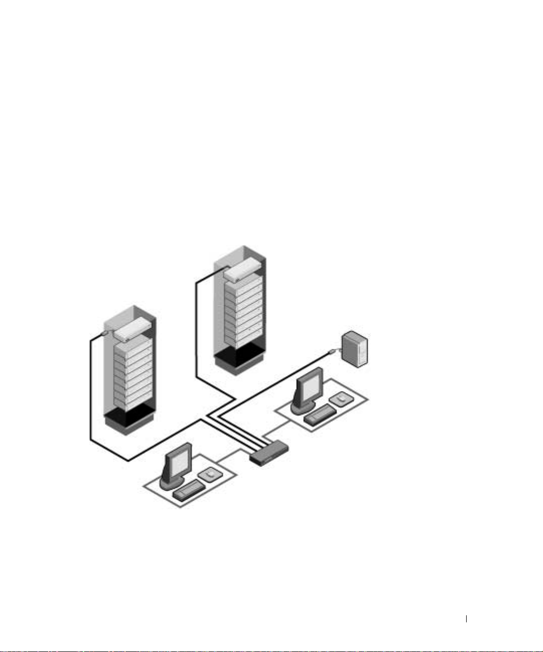
Figure 1-2. Example of a Console Switch Configu r ation
Console Switch
(tiered)
Legacy Switch
(tiered)
SIP
Module
Analog
Connection
Rack of Servers
Critical Server
Analog
Connection
Console Switch
(main)
Safety Precautions
Use the following safety guidelines to help ensure your own personal safety and to help protect your
system and working environment f rom potential damage.
Product Overview 9
Page 10

www.dell.com | support.dell.com
CAUTION: The power supplies in your system may produce high voltages and energy hazards, which
can cause bodily ha r m . Only tr ained service technicians are autho r iz ed t o rem o ve the covers and
access any of the components inside the system.
This document pertains only to the Dell Console Switch.
General
Observe and follow service markings:
• Do not service any product except as explained in your system documentation.
• Opening or removing covers that are marked with the triangular symbol with a lightning bolt
may expose you to electrical shock.
• Components inside these compartments should be serviced only by a trained service
technician.
– This product contains no serviceable components. Do not attempt to open.
• If any of the following conditions occur, unplug the product from the electrical outlet and
replace the part or contact your trained service provider:
– The power cable, extension cable, or plug is damaged.
– An object has fallen into the product.
– The product has been exposed to water.
– The product has been dropped or damaged.
– The product does not operate correctly when you follow the operating instructions.
• Keep your system away from radiators and heat sources. Also, do not block cooling vents.
• Do not spill food or liquids on your system components, and never operate the product in a
wet environment. If the system gets wet, see the appropriate section in your troubleshooting
guide or contact your trained service provider.
• Use the product only with approved equipment.
• Allow the product to cool before removing covers or touching internal components.
• Operate the product only from the type of external power source indicated on the electrical
ratings label. If you are not sure of the type of power source required, consult your service
provider or local power company.
NOTICE: To help avoid damaging your s ystem, be sure the volt age selection switch (if provided) on the
power supply is set for the voltage that mo st closely matches the AC power available i n your location.
• Be sure that your monitor and attached devices are electrically rated to operate with the
power available in your location.
• Use only power cables provided with this product.
10 Product Overview
Page 11

• To help prevent electric shock, plug the system and peripheral power cables into properly
grounded electrical outlets. These cables are equipped with three-prong plugs to help ensure
proper grounding. Do not use adapter plugs or remove the grounding prong from a cable.
• Observe extension cable and power strip ratings. Make sure that the total ampere rating of all
products plugged into the power strip does not exceed 80 percent of the ampere ratings limit
for the power strip.
• To help protect your system from sudden, transient increases and decreases in electrical
power, use a surge suppressor, line conditioner, or uninterruptible power supply (UPS).
• Position system cables and power cables carefully. Route cables so that they cannot be stepped
on or tripped over.
• Be sure that nothing rests on any cables.
• Do not modify power cables or plugs. Co nsult a licensed electrician or your power company
for site modifications. Always follow your local/national w iring rules.
Rack Mounting of Systems
• Refer to the rack installation documentation accompanying the rack for specific caution
statements and procedures.
• System rack kits are intended to be installed in a rack by trained service technicians. If a nonDell rack is utilized, be sure that the rack meets the specifications of a Dell rack.
• Elevated Ambient Temperature: If installed in a closed rack assembly, the operation
temperature of the rack environment may be greater than room ambient. Use care not to
exceed the rated maximum ambient temperature of the unit.
• Reduced Air Flow: Installation of the equipment in a rack should be such that the amount of
airflow required for safe operation of the equipment is not compromised.
• Mechanical Loading: Mounting of the equipment in the rack should be such that a hazard ous
condition is not achieved due to uneven me chanical loa ding .
• Circuit Overloading: Consideration should be given to the connection of the equipment to
the supply circuit and the effect that overloading of cir cuit s might have on overcurrent
protection and supply wiring. Consider equipment nameplate ratings for maximum current.
• Reliable Earthing: Reliable eart hing of rack mounted equipment should be maintained. Pay
particular att enti on to suppl y connec tions other t han dir ect connec tions to the bra nch circu it
(for example, use of power strips).
Product Overview 11
Page 12

www.dell.com | support.dell.com
12 Product Overview
Page 13

Installation
Getting Started
Before installing your Console Switch, refer to the following list to ensu re you have all items that
shipped with the appliance as well as other item s necessary for proper installation.
Supplied with the Console Switch
The following are supplied with the Console Switch:
• Console Switch appliance
•Power cord
•CAT 5 cable
• Rack mounting kit
• 0U mounting bracket
•One serial cable
• Console Switch Installer/User’s Guide
• Console Switch Quick Ins tallation Guide
2
Additional Items Needed
The following are additional items you may need to install your Console Switch:
• One Server Interface Pod (SIP) module and UTP cabling per attached server or switch
• 1U mounting (optional)
Rack Mounting Your Console Switch
NOTE: Rack mounting kits are sold separately.
Your Console Switch may be r ack mounted u sing brack ets availa ble throug h Dell. Befor e instal ling t he
appliance an d o t he r components in the rack cabinet (if not already installed), stabilize the rack in a
permanent location. Install your equipment starting at the bottom of the rack cabinet, then work
to the top. Avoid uneven loading or overloading of rack cabinets.
Installation 13
Page 14
www.dell.com | support.dell.com
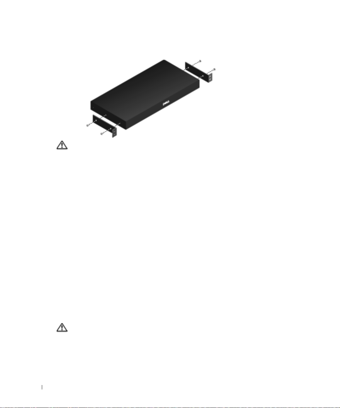
Figure 2-1. Console Switch Hor izontal Installati on
CAUTION: Ra ck Loading - Overloadin g or uneven loading of racks may result in sh elf or rack failure,
causing damage to equipment and possible personal injury. Stabili z e racks in a permanent location
before loading begins. Mount components beginn ing at the bottom of the rack, then work to the top. Do
not exceed your rack load rating.
To install the 1U s w itch mounting bracket:
1
Remove the screws on each side.
2
Line up the holes in the “long side” of the kit’s side brackets with the screw holes in the
switch.
3
With a Phillips screwdriver, fasten the mounting brackets to the switch using two screws on
each side.
4
Attach four cage nuts or clip nuts to the rack mounting flange of the rack cabinet so that the
nut is positioned on the inside of the rack.
5
Mount the switch assembly to the rack cabinet by matching the holes in the “short side” of
each bracket to an appropriate set of matching holes on your rack cabinet. Next, insert the
combination hex head screws through the slots in the bracket and the holes in the mounting
rail, then into the cage nuts or clip nuts.
Installing the Console Switch
Plug the supplied power cord into the back of the appliance and then into an appropriate power
source. Figure 2-2 illustrates one possible configuration for your Console Switch. See the following
detailed set of p roced ures to successfully i ns tal l yo ur a ppl ia nce .
CAUTION: To reduce the risk of el ectric shock or dama ge to your equipment:
14 Installation
- Do not disable the pow er co r d grounding plug. The grounding plug is an impor tant safety feature.
- Plug the power cord into a grounded ( ear thed) outlet th at is easily accessi ble at all times.
- Power down the unit by unplugging the po wer cord from the elec trical outlet or th e unit.
Page 15
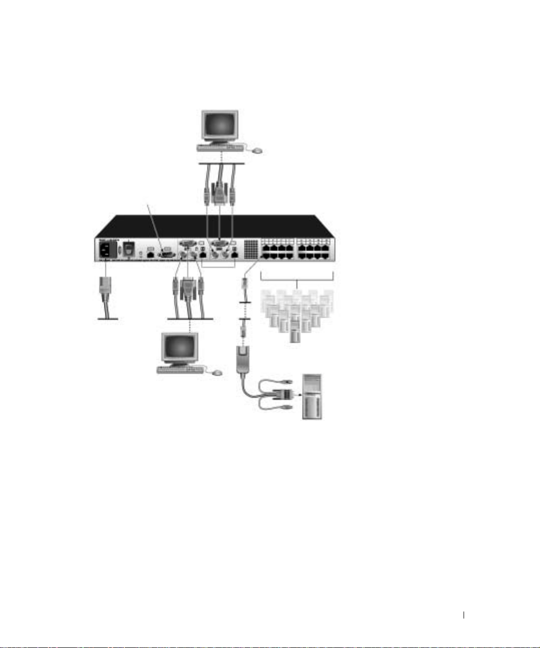
Figure 2-2. Basic Console Swit ch Configuration
Local User B (16-port model only)
Configuration Port
(for updating firmware)
Console Switch
Servers 2-16
Local User A
SIP
Server 1
To connect a SIP to each server:
1
Locate the SIPs for your Console Switch.
2
Attach the appropriately cable ends to the keyboard, monitor and mouse ports on the first server
you will be connecting to the appliance.
3
Attach one end of the CAT 5 cabling that will run between your SIP and Con sole Switch to
the RJ-45 connector on the SIP.
4
Connect the other end of the CAT 5 cable to the desired ARI port on the back of your
Console Switch.
5
Repeat steps 2 to 4 for all servers you wish to attach.
Installation 15
Page 16

NOTE: When connecting a Sun AVRIQ module, you must us e a m u lti-sync monitor to accommodate Su n
computers that support both VGA and sync-on-green or composit e sync.
To connect local peripherals:
1
Select the keyboard, monitor and mouse to be connected to local user A.
2
Locate the port set labeled A on the back of the appliance. Connect these peripherals to their
respective ports.
NOTE: For the mul tiuser, 16-port Console Switch, repeat these step s for the local user analog port set
labeled B.
Bundle and label the cables for easy identification.
3
www.dell.com | support.dell.com
Tiering Console Switches
You can tier multiple Cons ole Switches to enable one or two users to connect to up to 256 servers.
In a tiered system, each Analog Rack Interface (ARI) port on the main Console Switch will connect
to the Analog Console Interface (ACI) port on each tiered Console Switch. Each tiered switch can
then be connected to a server with a SIP. The example in Figure 2-3 shows one Console Switch
tiered under the main switch, enabling the connection of up to 15 primary servers and 16 secondary
servers. Using this configuration, you can tier 16 Console Switches under the main switch, enabling
the connection of up to 256 servers. Only one level of tiering is supported in this type of
configuration, which means that you cannot tier additional legacy switches or another Console
Switch. In this configuration, the local port On-Screen Configuration and Activity Reportin g
(OSCAR®) interface of the tiered Console Switch is disabled. All funct ions ar e per formed t hrou gh
the main Console Switch OSCAR.
NOTE: As shown in Figure 2-3, only local user A’s ACI port may be used for the tiered connection.
To tier multiple Console Switches:
1
Connect the Console Switch (tiered) to each server as described in the previous "Installing
the Console Switch" section.
2
Connect the local peripherals to local user A of the main switch as described in "Installing the
Console Switch" .
3
Attach one end of the CAT 5 cabling that will run between your main and tiered Console
Switch to the RJ-45 (ACI) connector of local user A on the tiered Console Switch.
4
Attach the other end of the CAT 5 cable to one of the 16 RJ-45 (ARI) ports on the main
Console Switch.
NOTE: The system will automatically tier the two switches together as one. All servers connected to the
5
16 Installation
tiered Console S w itch will display o n the main Console Swi tch server list in the OSCAR interface.
Repeat steps 3 and 4 for all additional tiered (secondary) Console Switches you wish to
attach.
Page 17
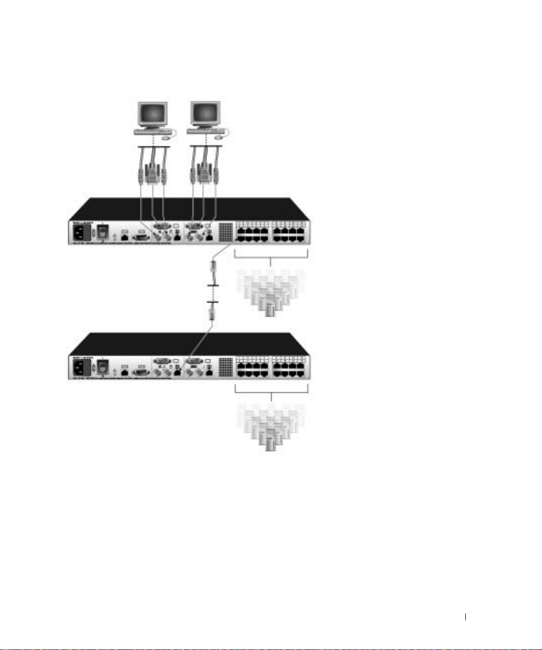
Figure 2-3. Console Switch C onfiguration with a Tiered Switch
Local user A
Tiered (secondary) Console Switch
Local User B (16 port model only)
Console Switch
ARI Ports
Primary
Servers
Secondary
Servers
Installation 17
Page 18

www.dell.com | support.dell.com
Adding Legacy Switches
You can add legacy switches to the Console Switch system for easy integration into your existing
configuration. In a tiered system, each ARI port will accommodate up to 24 servers. See the
following table for legacy switches compatible with the Console Switch system.
T able 2-1. Legacy Switch Support
Legacy Product Model Numbers
Avocent switches AV200, AV400, AV2000, 180ES, 2160ES
Dell switches Dell 180ES, 2160ES
18 Installation
Page 19

Figure 2-4. Console Switch C onfiguration with a Legacy KVM Switch
Local User
Console Switch
SIP PS/2 or USB or
AVRIQ PS/2, USB,
Sun, or Serial
SIP
Legacy Switch
Server 1
Legacy Switch
Server 2
To add a legacy KVM switch:
1
Mount the KVM switch into your rack cabinet. Locate a length of CAT 5 cabling to connect
between your Console Switch and the SIP for your switch.
2
Attach the keyboard, monitor and mouse connectors of the SIP to a user port on your tiered
switch.
3
Attach one end of the CAT 5 cabling to the RJ-45 connector on the SIP.
4
Connect the other end of the CAT 5 cable to an available port on the back of your Console
Switch.
5
Connect the servers to your tiered switch according to the instructions included with the
device.
6
Power cycle the tiered switch to enable the switch’s local user port recognize the SIP.
Installation 19
Page 20

7
Repeat steps 2 to 5 for all tiered switches you wish to attach to your system.
To connect local peripherals:
1
Select the keyboard, monitor and mouse to be connected to local user A.
2
Locate the port set labe l ed A on the back of the appliance. Connect these peripherals to their
respective ports.
NOTE: For the multiuser, 16-port Console Switch , re pea t thes e ste ps fo r th e loc al an alog por t set la bele d
B.
3
Bundle and label the cables for easy identification.
www.dell.com | support.dell.com
Setting Up Your Console Switch System
With the Console Switch system, you can auto detect and configure each port on your appliance.
"Basic Operation" provides detailed instructions on naming, customizat i on, an d OS CAR in te rf ace
setup and configuration.
20 Installation
Page 21

Basic Operation
Controlling Your System at the Local User Ports
The Console Switch features up to two local user port sets on the back of the unit that allow you to
connect a monitor and a PS/2 keyboard and mouse for direct access. The 8-port Console Switch
allows you to connect a single user, whereas the 16-port Console Switch allows you to connect two
local users. The appliance uses the On-Screen Configuration and Activity Reporting (OSCAR®)
interface, which utilizes intuitive menus to configure your system and select computers.
Viewing and Selecting Por t s an d Server s
3
Use the OSCAR
system. View your servers by name, port or the unique Electronic ID (EID) number embedded in
each Server Interface Pod (SIP). You will see an OSCAR interface-generated port list by default
when you first launch the OS CAR interface.
The
Port
column indicates the Analog Rack Interface (ARI) port to which a server is connected. If
you connect a le gacy k e y board, video, and mouse (KVM) switch to the appliance or a t i ered switch,
the port numbering displays the ARI port first, then the switch port to which the server is
connected. For example, in Figure3-1, servers 04-03 and 01-02 are connected to switches.
To access the
1
Press
Main
dialog box to view, configure and control servers in the Console Switch
Main
dialog box:
<Print Screen>
to launch the OSCAR interface. The
Main
dialog box appear s.
Basic Operation 21
Page 22

www.dell.com | support.dell.com
Figure 3-1. Main Dialog Box
NOTE: You can also press the <ctrl> key twice within one second to launch the OSCAR interface. You
can use this key sequence in an y place yo u see
<Print Screen> throughout this inst al ler/u ser ’s guide.
Viewing the Status of Your Switch
The status of the servers in your system is indicated in the right columns of the
The following table describes the status symbols.
Table 3-1. OSCAR Interface Status Symbols
Symbol Description
Main
dialog box.
22 Basic Operation
Server Interface Pod (SIP) is online (green circle).
SIP is offline or is not operating properly.
Connected switch is online.
Connected switch is offline or is not operat ing properly.
SIP is being upgraded (yellow circle).
Page 23

Table 3-1. OSCAR Interface Status Symbols (continued)
Symbol Description
SIP is being accessed by the indicated user channel (green
channel letter).
SIP is blocked by the indicated user channel (black
channel letter).
Selecting Servers
Use the
keyboard and mouse to the correct settings for that server.
To select servers:
Double-click the server name, EID or port number.
-orIf the display order of your server list is by port (
and press
-orIf the display order of your server list is by name or EID number (
depressed) , type the fi rs t few cha ract ers of the name of the s erver or the E ID numb er to es tabli sh i t
as unique and press
To select the previous server:
Press
previous and current connections.
To disconnect the user from a server:
Press
-orPress
selected. The status flag on your desktop displays
Main
dialog box to select servers. When you select a server, the appliance reconfigures the
<Enter>
.
<Print Screen>
<Print Screen>
<Print Screen>
Port
button is depressed), type the port number
Name
or
EID
button is
<Enter>
.
and then <Backspace>. This key combination toggles you between the
to access OSCAR and then click
and then <
Alt><0
>. This leaves the user in a free state, with no server
Disconnect
Free
.
.
NOTE: To clear all offline Server Interface Pods (SIPs) from the list, click Clear.
Soft Switching
Soft switching is the ability to switch servers using a hotkey sequence. You can soft switch to a server by
pressing
Screen Delay Time
will not display.
To configure servers for soft switching:
1
Press
<Print Screen>
and you press the key sequences before that time has elapsed, the OSCAR interface
<Print Screen>
and then typing the first few character s of its name or number. If you have set a
to launch the OSCAR interface. The
Main
dialog box appears.
Basic Operation 23
Page 24

www.dell.com | support.dell.com
2
Click
3
Set a
Screen>
4
Click OK.
Setup - Menu.
Screen Delay Time
being pressed and the
The
Menu
dialog box appears.
by typing the number of seconds of delay you want between
Main
dialog box displaying.
To soft switch to a server:
1
To select a server, press
button is depressed), type the port number and press
<Print Screen>
. If the display order of your server list is by port (
<Enter>
.
-orIf the display order of your server list is by name or EID number (
Name
or
EID
depressed), type the first few characters of the name of the server or the EID number to
establish it as unique and press <Enter>.
2
To switch back to the previous server, press
<Print Screen>
then <Backspace>.
Navigating the OSCAR Interface
This table describes how to navigate the OSCAR interface using the keyboard
and mouse.
Table 3-2. OSCAR Interface Navigation Basics
This Keystroke Does This
Print Screen Press <Print Screen> twice to send the <Print Screen>
keystroke to the currently se lected device.
<Print
Port
button is
F1 Opens the Help screen for the current dialog box.
Escape Closes the current dialog box without saving changes
Alt (Hotkey) Opens dialog boxes, selects or checks options and
Alt+X Closes the current dialog box and returns to the
Alt+O Selects the OK button, then returns to the previous
Single-clic k, E nt er In a text box, selects th e text for editing and en a b le s t he
24 Basic Operation
and retur n s t o th e previous one. In the Main dialog box,
it closes the OSCAR interface and returns to the flag. In
a message box, it closes the pop-up box and returns to
the current dialog box.
executes actions when used with underlined or other
designated letters.
previous one.
dialog box.
Left and Right Arrow keys to move the cursor. Press
<Enter> again to quit the edit mode.
Page 25

T a ble 3-2. OSCAR Interface Navigation Bas ic s (continued)
This Keystroke Does This
Enter Completes a switch in the Main dialog box and exits the
OSCAR interface. Performs the same function as the
OK button.
Print Screen, Backspace Toggles back to previous selection.
Print Screen, Alt+0 Immediately disengages user from a server; no server is
selected. Status flag displays Free. (This only applies to
the <0> on the keyboard and not the keypad.)
Print Screen, Pause Immediately turns on screen saver mode, and prevents
access to that specific console if it is password protected.
Up/Down Arrows Moves the cursor from line to line in lists.
Right/Left Arrows Moves the cursor between columns. When editing a text
box, these keys move the cursor within
the column.
Page Up/Page Down Pages up and down through lists and
Help pages.
Home/End Moves the cursor to the top o r bo ttom of a list.
Delete Deletes characters in a text box.
Numbers Type from the keyboard or keypad.
Configuring OSCAR Interface Menus
You can configure your Console Switch from the
button when initially setting up your appliance to identify servers by unique names. Select the
other setup features to manage routine tasks for your servers from the OSCAR menu.
T able 3-3. Setup Features to Manage Routine Tasks for Your Server s
Feature Purpose
Menu Change the server listing between numerically by port or
EID number and alphabetically by name.
Change the Screen Delay Time before the OSCAR interface
displays after pressing <Print Screen>.
Flag Change display, timing, color or location of the status flag.
Broadcast Set up to simultaneously control multiple servers through
keyboard and mouse actions.
Setup
dialog box in OSCAR. Click the
Names
Basic Operation 25
Page 26

T a ble 3-3. Setup Features to Manage Routine Tasks for Your Server s (c ontinued)
Feature Purpose
Scan Set up a custom scan pattern for up to 16 servers.
Security Set passwords to restrict server access.
Enable the screen saver.
Devices Identify the appropriate number of ports on an attached
legacy switch.
Names Identify serve r s by unique names.
www.dell.com | support.dell.com
Switch Choose the switch mode and the share mode time-out.
To access the
1
Press
2
Click
Figure 3-2. Setup Dialog Box
Setup
dialog box:
<Print Screen>
Setup
. The
Setup
to launch the OSCAR interface. The
dialog box displays.
Main
dialog box appears.
Assigning Server Names
Use the
Names
cable/server to another ARI port, the name and configuration will be recognized by the appliance.
Names
dialog box to identify individual servers by name rather than by port number. The
list is always sorted by port order. Names are stored in the SIP, so even if you move the
NOTE: If a server is turned off, the SIP will not appear in the Names list.
To access the
1
Press
2
Click
26 Basic Operation
Names
dialog box:
<Print Screen> to
Setup - Names.
launch OSCAR. The
The
Names
dialog box appears.
Main
dialog box appears.
Page 27

Figure 3-3. Names Dialog Box
NOTE: If the server list changes, t he mouse cursor turns into an hourglass as the list is automatically
updated. No mous e or keyboard input is accepted until the list update is complete.
To assign names to servers:
1
In the
Names
dialog box, select a server name or port number and click
Modify
Figure 3-4. Name Modify Dialog Box
dialog box displays.
Modify
. The
Name
2
Type a name in the
New Name
box. Names of servers may be up to 15 characters long. Legal
characters include: A to Z, a to z, 0 to 9, space and hyphe n.
3
Click
OK
to transfer the ne w na me to the
you click
4
Repeat steps 1 to 3 for each server in the system.
OK
in the
Names
dialog box.
Names
dialog box. Your se lection is not sa ved un ti l
Basic Operation 27
Page 28

5
Click
OK
in the
Names
dialog box to save your changes.
-orClick
X
or press <Escape> to exit the dialog box without saving changes.
NOTE: If a SIP has not been assigned a name, the EID is used as the default name.
Assigning Device Types
While the appliance automatically discovers legacy KVM switches, you will need to specify the
number of ports on the legacy switch in the
switch type such as
from the list. The
Sw-8
or
Sw-24
appear in the
Modify
button displays, allowing you to assign it the appropriate number of ports.
Devices
Typ e
dialog box. You will see an indication of the
category for the tiered switch. Select the switch
www.dell.com | support.dell.com
NOTE: The Modify button will only be available if a configurable switch is sele cted.
To access the
1
Press
2
Click
Figure 3-5. Devices Dialog Box
Devices
<Print Screen>
dialog box:
to launch O SCAR. The
Setup - Devices. The
Devices
Main
dialog box appears.
dialog box appear s.
When the Console Switch discovers a legacy switch, the port numbering changes to accommodate
each server under that switch. For example, if the switch is connected to ARI port 6, the switch port
is listed as 06 and each server under it is numbered sequentially 06-01, 06-02 and so on.
To assign a device type:
1
In the
2
Click
Devices
Modify
dialog box, select the desired port number.
. The
Device Modify
dialog box appears.
28 Basic Operation
Page 29

Figure 3-6. Device Modify Dialog Box
3
Choose the number of ports supported by your legacy switch and click OK.
4
Repeat steps 1 to 3 for each port requiring a device type to be as signed.
5
Click OK in the
NOTE: Changes made in the Device Modify dialog box are not saved until you click OK in the Devices
dialog box.
Devices
dialog box to save settings.
Changing the Display Behavior
Use the
OSCAR interface. The display order setting alters h ow serv ers wi ll d isplay in several s cr eens i ncludi ng
the
To access the
Menu
Main, Devices
1
Press
<Print Screen>
2
Click
Setup
dialog box to change the displa y order of se rvers and set a
and
Menu
-
Broadcast
dialog box:
Menu
dialog boxes.
to launch the OSCAR interface. The
in the
Main
dialog box. The
Menu
dialog box appears.
Main
Screen Delay Tim
dialog box appears.
e for the
Basic Operation 29
Page 30

www.dell.com | support.dell.com
Figure 3-7. Menu Dialog Box
To choose the default display order of servers:
1
Select
Name
to display servers alphabetically by name.
-orSelect
EID
to display servers n umerically by EID num ber.
-orSelect
Port to display
2
Click OK.
To set a
Screen Delay Time
1
Type in the number of seconds (0 to 9) to delay the OSCAR interface display after you press
servers numerically by port number.
for the OSCAR interface:
<Print Screen>. Entering <0> launches the OSCAR interface with no delay.
2
Click OK.
Setting a
Screen Delay Time
displaying. To perform a soft switch, see "Soft Switching"
allows you t o complete a soft switch without the OSCAR interface
.
Controlling the Status Flag
The status flag displa y s on your de skt o p and shows the name or EID number of the selected server
or the status of the selected port. Use the
name or EID number, or to change the flag color, opacity, display time and location on th e de sktop .
Table 3-4. OSCAR Status Flags
Flag Description
30 Basic Operation
Flag
dialog box to configure the flag to display by server
Flag type by name
Flag type by EID number
Page 31

Table 3-4. OSCAR Status Flags (continued)
Flag Description
Flag indicating that the user has been disconnected
from all systems
Flag indicating that Broadcast mode is enabled
To access the Flag dialog box:
1
Press
<Print Screen>
2
Click
Setup
-
Figure 3-8. Flag Dialog Box
Flag
. The
. The
Main
dialog box appears.
Flag
dialog box appears.
To determine how the status flag is displayed:
1
Select
Name
or
EID
to determine what information will be displayed.
2
Select
Displayed
to show the flag all the time or select
seconds af t er switching.
3
Select a flag color in
4
In Display mo de, se lect
Display Colo
Opaque
for a solid colo r flag or sel ect
r.
through the flag.
5
To position the status flag on the desktop:
a
Click
Set Position
b
Left-click on the title bar and drag to the desired location.
c
Right-click to return to the
to gain access to the
Flag
dialog box.
Timed
Set Position Flag
to display the flag for only five
Transparent
to see the desktop
screen.
Basic Operation 31
Page 32

www.dell.com | support.dell.com
Figure 3-9. Set Position Flag
NOTE: Changes made to the flag position are not saved until you click OK in the Flag dialog box.
Click OK to save settings.
6
-orClick
X
to exit without saving changes.
Setting Console Security
The OSCAR interface enables you t o set secu rity on your local user port console. You can establish a
screen saver mode that engages after your console r emains unused for a specified
engaged, your console will remain locked until you press any key or move the mouse. You will then need to
type in your password to continue.
Use the
Security
dialog box to lock your console with password protection, set or change your
password and enable the screen saver.
NOTE: If a password has been previ ou sly set, you will have to en ter the password befo r e yo u ca n
access the Security dialog box.
To access the
1
Press
2
Click
Security
dialog box:
<Print Screen> to launch the OSCAR interface
Setup
-
Security
. The
Security
dialog box appear s.
. The
Main
Inactivity Time
dialog box appear s.
. Once
Figure 3-10. Security Dialog Box
To set or change the password:
1
Single-click and press <Enter> or double-cli ck in the
32 Basic Operation
New text
box.
Page 33

2
Type the new password in the
New text
box and press
<Enter>
.
P assw ords must contain both alp ha and nu meri c cha racte rs, are case sensitive and may be up to
12 characters long. Legal characters are: A to Z, a to z, 0 to 9, space and hyphen.
3
In the
Repeat
box, type the password again and press
4
Click OK to change only your password, and then close the dialog box.
NOTE: If you should lose or forget your password, you must return your switch for service or technical
support.
<Enter>
.
To password protect your console:
1
Set your password
Select
2
3
Enable Screen Saver.
Type the number of minutes for
as described in the previous procedure.
Inactivity Time (from 1 to 99)
to delay activation of
password protection and the screen saver feature.
4
For Mode, select
Screen
.
CAUTION: Monitor damage can result from the use of Energy mode with monitors not compliant with
E
NERGY STAR®.
(Optional) Click
5
to the
Security
6
Click OK.
Energy
Test
if your monitor is E
NERGY STAR
to activate the scr een saver test , which lasts 10 seconds then r eturns y ou
dialog box.
®
compliant; otherwise select
To log in to your console:
1
Press any key or move the mouse.
2
The
Password
3
The
Main
dialog box appears. Type your password, then click OK.
dialog box appears if the password was entered properly.
To remove password protection from your console:
1
From the
your password, then click
2
In the
Leave the box blank. Press
3
Single-click and press
<Enter>
4
Click OK to eliminate your password.
Main
Security
.
dialog box, click
Setup - Security
OK
.
dialog box, single-click and press
<Enter>
<Enter>
.
or double-click in the
; the
Authorize
<Enter>
Repeat
dialog box appears. Type
or double-click in the
New
box. Leave the box blank. Press
To enable the screen saver mode with no password protection:
1
If your console does not require a password to gain access to the
Security
dialog box, proceed
to step 2.
-orIf your console is password protected, see the previous procedure, then go to step 2.
box.
Basic Operation 33
Page 34

2
Select
Enable Screen Saver
3
Type the number of minutes for
.
Inactivity Time (from 1 to 99)
to delay activation of the
screen saver.
4
Choose
CAUTION: Monitor damage can result from the use of Energy mode with monitors not compliant with
E
(Optional) Click
5
to the
6
Click OK.
Energy
NERGY STAR®.
Security
if your monitor is E
Test
to activate the screen sa ver test, which lasts 10 seconds th en ret urns you
NERGY STAR
dialog box.
®
compliant; otherwise select
Screen
.
www.dell.com | support.dell.com
NOTE: Activation of the screen saver mode disconnects the user from a server; no serve r is selected.
The status flag displays Free.
To exit the screen saver mode:
Press any key or move your mouse. The
Main
dialog box appears and any previous server
connection will be restored.
To turn off the screen saver:
1
In the
2
Click OK.
Security
dialog box, clear
Enable Screen Saver
.
To immediately turn on the screen saver:
<Print Screen>
Press
, then press
<Pause>
.
Displaying Version Information
The OSCAR interface enables you to display the versions of the Console S witch and the SIP
firmware. For optimum performance, keep your firmware current. For more information, see
"Appendix A: Flash Upgrades".
To display version information:
1
Press
<Print Screen>
2
Click
Commands - Display V ersions .
lists the subsystem versions in the appliance.
. The
Main
dialog box appears.
The
Version
dialog bo x a ppe ars . Th e top ha lf of the box
34 Basic Operation
Page 35

Figure 3-11. Version Dialog Box
3
Click
SIP
to view individual SIP version information.The
Figure 3-12. SIP Selection Dialog Box
SIP Selection
dialog box appears.
4
Select a SIP to view and click the
Version
button. The
SIP Version
more information on loading firmware, see "Appendi x A: Flash Upgrades"
dialog box appears. For
.
Basic Operation 35
Page 36

www.dell.com | support.dell.com
Figure 3-13. SIP Version Dialog Box
5
Click X to close the
SIP Version
dialog box.
Resetting a SIP
PS/2 SIPs can be reset using the
NOTE: This procedure is only relev ant where your Consol e Switch system involves a PS/2 SIP attached
to a tiered swi tch . On th ese occa si ons , it may be ne ces sary to re set the SIP wh en th e ti ered swi tch is no t
recognized.
NOTE: If a reset is performed when a Console Switch is connected directly to a server and not a tiered
switch, the mouse/ keyboard may fail to respond. When this occ urs, the target server requires a reboot .
To reset a SIP:
1
Press <Print Screen>. The
2
Click
Commands - D isplay Versions
3
Click
SIP.
The
SIP Selection
4
Select the PS/2 SIP that you wish to view and click
appears.
Reset
button in the
Main
dialog box will appear.
. The
dialog box appear s.
SIP Version
Version
dialog box appears.
Version
dialog box.
. The
SIP Version
dialog box
36 Basic Operation
Page 37

Figure 3-14. SIP Version Dialog Box
Click
Reset
5
. A warning messag e appears, warning that the function is for tiered switches only
and that resetting the SIP could result in the need to reboot the target server.
6
Click OK to proceed with the reset.
or
7
Press <ESC> to exit.
Resetting Your Keyboard and Mouse
If a keyboard or mouse locks up, you may be able to re-establish operation of these peripherals by
issuing a reset command.
To reset the mouse and key board values:
1
Press <Print Screen>. The
2
Click
Commands - D e vice Reset
Main
dialog box appear s.
. A message box displays requesting that you confirm the
reset.
3
Click OK. A message appears indicating that the mouse and keyboard have been reset.
4
Click X to close the message box.
Basic Operation 37
Page 38

www.dell.com | support.dell.com
Figure 3-15. Commands Dialog Box
Scanning Your System
In scan mode, the appliance automatically scans from port to port (server to server). You can scan
up to 16 servers, specifying which servers to scan and the number of seconds that each server will
display. The scanning order is determined by the order in which the servers are added to the
list. The list is always shown in scanning order. You can, however, choose to display the server’s
name or EID number by pressing the appropriate button.
To add servers to the scan list:
1
If the OSCAR interface is not open, press
2
Click
Setup - Scan
. The
Scan
dialog box appears.
<Print Screen>
. The
Main
dialog box appears.
Scan
38 Basic Operation
Page 39

Figure 3-16. Scan Dialog Box
The dialog box contains a listing of all servers attached to your appliance. Click the check box
3
next to the servers you wish to scan.
-orDouble-click on a server’s name or port.
-orPress <
Alt >
and the number of the server you wish to scan. You can select up to 16 serve rs from
the entire list.
4
In the
Scan Ti me
box, type the number of seconds (from 3 to 99) of desired time before the
scan moves to the next server in the sequence.
5
Click OK.
To remove a server from the scan list:
1
In the
Scan
dialog box, deselect the check box next to the server to be removed.
-orDouble-click on the server’s name or port.
-orClick the
2
Click OK.
Clear
button to remove all servers from the scan list.
To set the Scan du ration:
1
Type a value in the
Scan Time
box. The duration you type must be a minimum of 3 seconds
and a maximum of 255 seconds.
To start the scan mode:
1
If the OSCAR interface is not open, press
2
Click
Commands
. The
Commands
<Print Screen>.
dialog box appears.
The
Main
dialog box will appear.
Basic Operation 39
Page 40

www.dell.com | support.dell.com
Figure 3-17. Commands Dialog Box
3
Select
Scan Enable
4
Click X to close the Commands dialog box.
NOTE: Scanning will begin when the Main dialog box or flag is displayed. Scanning is inhibited in any
other OSCAR dialog box.
in the
Commands
dialog box.
To cancel scan mode:
1
Select a server if the OSCAR interface is open.
-orMove the mouse or press any key on the keyboard if the OSCAR interface is not open.
Scanning will stop at the currently selected server.
-orPress
2
3
<Print Screen>
Click
Commands
Clear
Scan Enable.
. The
. The
Main
dialog box appears.
Commands
dialog box appears.
Running System Diagnostics
You can validate the in tegr ity of your sy stem t hrough the
checks the main board functional sub-systems (memory, communications, switch control and the
video channels) for each system controller. When you select the
receive a warning indicating that all users (remote and local) will be disconnected. Click
confirm and begin the test.
Diagnostics
The
The bottom portion divides the tested SIPs into three categories:
40 Basic Operation
Run Diagnostics
Run Diagnostics
command. This command
option, you will
OK
to
dialog box displays. The top section of the dialog box displays the hardware tests.
On-line, Offline
or
Suspect
.
Page 41

Figure 3-18. Diagnostics Dialog Box
NOTE: A SIP may appear to be offline while it is being upgraded.
Next to each item to be tested, you will see a pass (green circle) or fail (red x) symbol display to the
left of each item as that test finishes. The following table details each of the tests.
Table 3-5. Diagnostic Test Details
Test Description
Memory Tests Reports on the condition of the main board RAM
Firmware CRCs Validates the current firmware images stored in the
system’s FLAS H
Comm Interfaces Validates internal communication pathways
Switch Controller test Verifies the switch matrix controller is accessible
and functional
On-line SIPs Indicates the to t a l nu m b er of cu r rently connec te d and
powered SIPs
Offline SIPs Indic a te s the number of SIPs that have been connecte d
successfully in the past and are apparently powered down
Suspect SIPs In dicates the num b er of SIPs th a t have been detec ted,
but are either unavailable for connection or have dropped
packets during the ping tests
To run diagnostic tests:
1
If the OSCAR interface is not open, press
2
Click
Commands - Run Diagnostics
<Print Screen>
. The
Main
. A warning message appears indicating that all users will
be disconnected.
dialog box appears.
Basic Operation 41
Page 42

www.dell.com | support.dell.com
Figure 3-19. Diagnostics Warning Message Box
3
Click
OK
to begin diagnostics.
-orClick
X
or press <Escape> to exit the dialog box without running a diagnostic test.
4
All users are disconnected and the
5
As each test is finished, a pass (green circle) or fail (red x) symbol appears. The test is
Diagnostics
dialog box displays.
complete when the last te st’s symbol d isplays.
Broadcasting to Servers
The user can simultaneously control more than one server in a system to ensure that all selected
servers receive identical input. You can choose to broadcast keystrokes and/or mouse movements
independently.
NOTE: You can broadcast to up to 1 6 ser v ers at a time, one server per ARI port.
To access the Broadcast dialog box:
1
Press
2
Click
42 Basic Operation
<Print Screen>
. The
Setup - Broadcast
Main
dialog box appears.
. The
Broadcast
dialog box appears.
Page 43

Figure 3-20. Broadcast Dial og Box
NOTE: Broadcasting Keystrokes - The keyboard state must be identical for all servers receiving a broadcast
to interpret keystrokes identically. Specifically, the <Caps Lock> and <Num Lock> modes must be the same
on all keyboards. While the appliance attempts to send keystrokes to the selected servers simultaneously,
some servers may inhibit and thereby delay the transmission.
NOTE: Broadcasting Mouse Movements - For the mouse to work accurately, all systems must have
identical mouse dr ivers, desktops (suc h as identically placed icons) and video resolutions. In addition,
the mouse must be in exact ly the same place on all sc r eens. Because these conditions are extremel y
difficult to achieve, broadcasting mouse movements to multiple systems may have unpredictable results.
To broadcast to selected servers:
1
From the
Broadcast
dialog box, click to en able the mouse an d/or ke yboard check box es for the
servers that are to receive the broadcast commands.
-orPress the <
<Alt><K> to select the keyboard check box and/or
Up>
or <
Down>
arrow keys to move the cursor to the target server. Then press
<Alt><M> to select the mouse check
box. Repeat for additional servers.
2
Click
OK
to return to the
3
Click
Commands
4
Click the
to save the settings and return to the
Main
dialog box.
. The
Commands
Broadcast Enable
dialog box appears.
check box to activate broadcasting. The
Setup
dialog box. Click X or press
Broadcast Enable
dialog box appears.
<Escape>
Basic Operation 43
Page 44

www.dell.com | support.dell.com
Figure 3-21. Broadcast Enable Dialog Box
Click
OK
5
Commands
6
If broadcasting is enabled, type the information and/or perform the mouse movements you
to enable the broadcast. Click X or press
dialog box.
Escape
to cancel and return to the
want to broadcast from the user station. Only servers in the list are accessible.
NOTE: The other user (16-port switch only) is disabled when broadcast mode is enabled.
To turn broadcasting off:
From the
Commands
dialog box, disable the
Broadcast Enable
check box.
Changing Your Switch Mode (16-port Console Switch Only)
Your Console Switch allows you to connect to attached servers using two methods:
Cooperative
Select
Preemptive (default setting) to allow any user to select any server at any time; a request from
another user disconnects the current user without warning.
-orSelect
Cooperative to maintain the current user connection; the current user won’t be
disconnected if another user requests connection.
To access the Switch dialog box:
1
Press
2
Click
44 Basic Operation
.
<Print Screen>
Setup - Switch
. The
. The
Main
dialog box appears.
Switch
dialog box appear s.
Preemptive
and
Page 45

Figure 3-22. Switch Dialog Box
Select either
3
Preemptive
or
Cooperative
as your switch mode.
Basic Operation 45
Page 46

www.dell.com | support.dell.com
46 Basic Operation
Page 47

Appendices
Appendix A: Flash Upgrades
Upgrading the Console Switch
You can upgrade the firmware of your Console Switch by using a special update utility provided by
Dell. This utility automa tically configures the port communications settings to allow direct
downloading from the connected server.
Items Needed for the Upgrade
The following items are required to upgrade your Console Switch firmware:
®
• Server running Microsoft
Windows 2000
• Available serial port (COM port) on the server
• Standard serial cable th at conn ects th e swi tch an d the se rve r
• Firmware update
Upgrading Firmware
To upg rade firmware:
1
Connect the standard serial cable to a COM port on the server and to the serial connector on
the back panel of the switch. Make a note of which COM port you have chosen, then turn on
the switch.
2
Go to
http://www.dell.com/support
file. Once the download is complete, navigate to the drive where you have saved the firmware
update and unzi p th e file.
3
Double-click to run the file
4
In the dialog box that displays, select the desired language and COM port.
5
Click
Load
. The update begins.
6
Once the firmware is updated, the followin g message displays:
Done
to exit the dialog box.
7
The switch automatically reboots after the upgr ade is completed.
Windows NT®, Windows® 95, Windows 98 or
and click on
WUpDateDELL.exe
Downloads
.
to access the firmware upgrade
Download complete.
Click
4
Appendices 47
Page 48

Possible Error Conditions
If the download does not execute properly, verify the following:
• Verify that the COM port is correct.
• Verify that no other program is currently using the COM port, or that a previous DOS
window/shell is open that had used the desired COM port.
• Verify that no other copies of the WUpDate utility are currently running.
• Verify that a serial cable is used.
• Verify in the selected COM port’s Advanced Port settings that the FIFO buffers are selected
and that the receive buffer is set to High.
www.dell.com | support.dell.com
CAUTION: While upgrading, do not use your comp uter for anything else or switch between wi nd ows.
Close all other wi ndows if necessary. If the upgrade was unsuccessful (s uch as during a power
outage), repea t t he procedure.
48 Appendices
Page 49

Upgrading the SIP
The Server Interface Pods (SIPs) can be upgraded individually or simultaneously.
NOTICE: Do not cycle power to the server or disconnect the SIP during this process. A loss of power
will render the SIP inoperable and require the unit be returned to the factory for repair.
To simultaneously upgrade multiple SIPs:
1
Press <Print Screen>. The
2
Click
Commands-S IP Status
Figure 4-1. SIP Status Dialog Box.
Main
dialog box appear s.
. The
SIP Status
dialog box appear s.
Click one or more types of SIPs you wish to up grade. Click
3
box appears.
Figure 4-2. SIP Upgrade Dialog Box
Click OK to initiate the upgrade and return to the
4
Upgrade
SIP Status
. The
dialog box.
SIP Upgrade
Appendices 49
dialog
Page 50

www.dell.com | support.dell.com
To upgrade SIP firmware individually:
1
Press <Print Screen>. The
2
Click
Commands-Display Versions
Figure 4-3. Version Dialog Box
3
Click
SIP
to view individual SIP version information.
Figure 4-4. SIP Selection Dialog Box
Main
dialog box appear s.
. The
Version
dialog box appear s.
4
Select the SIP that you wish to upgra de an d cl ic k th e
box appears.
50 Appendices
Version
button. The
SIP Version
dialog
Page 51

Figure 4-5. SIP Version Dialog Box
5
Click the
Figure 4-6. SIP Load Dialog Box
Load Firmware
button. The
SIP Load
dialog box appears.
Click OK to initiate the upgrade and return to the
6
NOTE: During an upgrade, the SIP status indicator in the Main dialog box will be yellow. The SIP is
unavailable while an upgrade is in progress. When an upgrade is initiated, any current connection to the
server via the SIP will be terminated.
SIP Status
dialog box.
Appendices 51
Page 52

www.dell.com | support.dell.com
Appendix B: Technical Specifications
T a ble 4-1. Technical Specifications
Server Ports
Number 8 or 16
SIP Types
Connectors RJ-45
Sync Types Separate horizontal and vertical
Plug and Play DDC2B
Video Resolution Analog Port Maximum 1600x1280@ 75 Hz
Update Port
Number
Type Serial RS232
Analog Port
Number 1 (8-port Console Switch), 2 (16-port Console Switch)
Type PS/2, VGA, and ACI
Connectors PS/2 MiniDIN, 15 Pin D,
Dimensions
Dimensions (H x W x D)
We ight 3 .6 kg (8 lb) without cables
Heat Dissipation 92 BTU/Hr
Power Consumption 12.5 W
AC-input power 40 W maximum
AC-input voltage rating 100 to 240 VAC Autosensing
AC-input current rating 0.5 A
AC-in put cable
AC-frequency 50/60 Hz
Temperature
PS/2 and USB
Avocent™ AVRIQ PS/2, USB, Sun, Serial
1
RJ-45
4.36 x 42.9 x 16.56 cm 1U form factor
(1.72 x 16.9 x 6.52 inches)
18 AWG three- wire cable , with a th ree-lead IEC-320
receptacle on the power supply end and a country or region
dependent plug on the power resource end
o
to 50o Celsius (50o to 122o Farenheit) operating
10
o
-20
to 60o Celsius (-4o to 140o Farenheit) nonoperating
52 Appendices
Page 53

T a ble 4-1. Techni c al Sp ec ifications (continued)
Humidity
20 to 80% noncondensing operating
5 to 95% noncondensing nonoperating
Appendices 53
Page 54

www.dell.com | support.dell.com
Appendix C: Notifications
USA Notification
CAUTION: Changes or modifications to this unit not expressly approved by the party responsible for
compliance coul d vo id the user's authority to operate the equipme nt.
NOTE: This equipment has been tested and found to comply with the limits for a Class A digital device,
pursuant to Par t 15 of the FCC Rules. The se limits are designed to provide reasonabl e protection agai nst
harmful interfe rence when the equipment is operated in a commer cial environment. This equipment
generates, uses and can radiate radi o frequency energy a nd, if not installed and used in accordanc e
with the instruction manual, may cause harmful interference to radio communications. Operation of this
equipment in a residential area is li kely to cause harmfu l interference in which case the user wil l be
required to correct the interference at his own expense.
Canadian Notification
This digital apparatus does not exceed the Class A limits for radio noise emissions from digital
apparatus set out in the Radio Interference Regulations of the Canadian Department of
Communications.
Le présent appareil numérique n'émet pas de bruits radioélectriques dépassant les limites
applicables aux appareils numériques de la classe A prescrites dans le Règlement sur le brouillage
radioélectrique édicté par le Ministère des Communications du Canada.
Japanese Approvals
Taiwanese Approvals
54 Appendices
Page 55

Agency Approvals
UL/cUL (UL 60950/CSA 22.2 No. 60950:2000)
ICES-003
NOM-019-SCFI-1993
IRAM S Mark (Resolution 92/98)
ACA AS/NZS 55022, class A
CNS 13438
FCC Class A, EN60950:2000, EN55022:1998, EN55024:1998, EN61000-3-3:1995 +A1,A2.
GS
GOST-R
VCCI
CCC
SASO
MIC/RRL, Republic of Korea EMI Standard Certificate Number: E-F900-01-2012 (A)
Appendices 55
Page 56

www.dell.com | support.dell.com
56 Appendices
Page 57

Index
A
ACI, 16
Analog Console Interface, See
ACI
Analog Rack Interface, See
ARI
ARI, 7, 16, 18, 26, 28
AVRIQ, 8
Sun, 16
B
Broadcasting, 42
C
Comm Interfaces
Checking, 41
D
Device types
Assigning, 28
Display behavior
Changing, 29
Display Color, 32
Electronic ID, See EID
Energy, 33
F
Firmware
Upgrading, 47
Firmware CRCs, 41
FLASH
Upgrade, 9
Flash
Upgrading, 47
K
Keep Al iv e, 7
L
Legacy KVM, 19
Legacy Switches
Adding, 18
M
Memory Te sts, 41
Changing, 33
Removing, 34
S
Scan list, 38
Scan mode, 39
Cancelling, 40
Scanning, 38
Screen Delay Time, 24, 29
Screen Saver
Enabling, 33
Testing, 33
Screen saver
Mode, 34
Security, 8, 32, 34
Server names
Assigning, 26
SIP, 49
Offline, 23
Resetting, 36
Upgrading, 49
Soft switching, 23
Status flag
Controlling, 31
Positioning, 32
Switch status, 22
E
EID, 21, 23, 31
P
Password
System Diagnostics
Running, 40
Index 57
Page 58

T
Tiering, 9, 16
V
Version Information
Displaying, 35
58 Index
 Loading...