

Page 1

Dell PowerEdge C5220
COMMENT
COMMENT
COMMENT
COMMENT
COMMENT
COMMENT
COMMENT
COMMENT
Using the Baseboard
Management Controller
Page 2

Typographic Conventions
COMMENT
COMMENT
Several different typographic conventions are used throughout this manual.
Refer to the following examples for common usage.
Bold type face denotes menu items, buttons and application names.
NOTE: A note indicates important information that will help a user make better use
of a computer system.
CAUTION: A caution indicates a potential for property damage, personal injury, or
death.
____________________
Information in this publication is subject to change without notice.
© 2010-2011DellInc.All rights reserved.
Reproduction of these materials in any manner whatsoever without the written permission of Dell Inc.
is strictly forbidden.
Trademarks used in this text: Dell™, the DELL logo, and PowerEdge™ are trademarks of Dell Inc.
Microsoft
in the United States and/or other countries. Red Hat
trademarks of Red Hat, Inc. in the United States and/or other countries. SUSE™ is a trademark of
Novell Inc. in the United States and other countries. Citrix
registered trademarks or trademarks of Citrix Systems, Inc. in the United States and/or other countries.
VMware
countries.
Other trademarks and trade names may be used in this publication to refer to either the entities claiming
the marks and names or their products. Dell Inc. disclaims any proprietary interest in trademarks and
trade names other than its own.
®
and Windows® are either trademarks or registered trademarks of Microsoft Corporation
®
is a registered trademarks or trademarks of VMWare, Inc. in the United States or other
®
and Red Hat Enterprise Linux® are registered
®
, Xen®, and XenServer® are either
April 2011 P/N Rev. A00
Page 3

Contents
Introduction . . . . . . . . . . . . . . . . . . . . . . . . . . . . . . . 5
Supported Platform
BMC Key Features and Functions
Using the Web UI
Logging in to the Web User Interface
System Features
. . . . . . . . . . . . . . . . . . . . . . . . . . . 5
. . . . . . . . . . . . . . . . . . . . 5
. . . . . . . . . . . . . . . . . . . . . . . . . . . . 5
. . . . . . . . . . . . . . . . . . 6
. . . . . . . . . . . . . . . . . . . . . . . . . . . . . 8
System Information. . . . . . . . . . . . . . . . . . . . . . . . . 8
Component Information . . . . . . . . . . . . . . . . . . . . . . 9
Server Identify
Firmware Update
Front Panel User Interface
. . . . . . . . . . . . . . . . . . . . . . . . . . . 10
. . . . . . . . . . . . . . . . . . . . . . . . . . 11
. . . . . . . . . . . . . . . . . . . . . . . 13
Power Button. . . . . . . . . . . . . . . . . . . . . . . . . . . . 13
LEDs . . . . . . . . . . . . . . . . . . . . . . . . . . . . . . . . 13
System Information
System Information
List FRU
Component Information
Server Health
. . . . . . . . . . . . . . . . . . . . . . . . . . . 16
. . . . . . . . . . . . . . . . . . . . . . . . . 16
. . . . . . . . . . . . . . . . . . . . . . . . . . . . . . . 16
. . . . . . . . . . . . . . . . . . . . . . 17
. . . . . . . . . . . . . . . . . . . . . . . . . . . . . . 18
Sensor Readings . . . . . . . . . . . . . . . . . . . . . . . . . . 19
Sensor Readings With Thresholds. . . . . . . . . . . . . . . . . 20
Temperature Monitoring
Current Monitoring
. . . . . . . . . . . . . . . . . . . . . . 21
. . . . . . . . . . . . . . . . . . . . . . . . . 22
FAN Control and Monitoring . . . . . . . . . . . . . . . . . . . . 22
Event Log
. . . . . . . . . . . . . . . . . . . . . . . . . . . . . . 23
Configuration
Alerts
. . . . . . . . . . . . . . . . . . . . . . . . . . . . . . . . 26
Mouse Mode
. . . . . . . . . . . . . . . . . . . . . . . . . . . . . . 24
. . . . . . . . . . . . . . . . . . . . . . . . . . . . 28
3
Page 4

Network . . . . . . . . . . . . . . . . . . . . . . . . . . . . . 29
SOL . . . . . . . . . . . . . . . . . . . . . . . . . . . . . . . . 32
. . . . . . . . . . . . . . . . . . . . . . . . . . . . . . . 34
SNMP
. . . . . . . . . . . . . . . . . . . . . . . . . . . . . . . 35
SMTP
. . . . . . . . . . . . . . . . . . . . . . . . . . . . . . . 36
Users
PEF . . . . . . . . . . . . . . . . . . . . . . . . . . . . . . . . 40
SSL Certificate
Web Session
. . . . . . . . . . . . . . . . . . . . . . . . . . 42
. . . . . . . . . . . . . . . . . . . . . . . . . . . 44
Remote Control
. . . . . . . . . . . . . . . . . . . . . . . . . . . . 45
Console Redirection . . . . . . . . . . . . . . . . . . . . . . . 45
Power Control . . . . . . . . . . . . . . . . . . . . . . . . . . 49
Maintenance
Languages
IPMI 1.5 / 2.0 Command Support List
. . . . . . . . . . . . . . . . . . . . . . . . . . . . . . 51
. . . . . . . . . . . . . . . . . . . . . . . . . . . . . . . 51
. . . . . . . . . . . . . . . . . 52
4
Page 5

Introduction
This section introduces the Baseboard Management Controller (BMC) and
includes the requirements for web-based graphical user interface (GUI),
keyboard, video, and mouse (KVM), and virtual media.
Supported Platform
PowerEdge C5220
BMC Key Features and Functions
The following lists the supported features of the BMC:
• Support for IPMI v1.5 and v2.0
• Out-of-band monitoring and control for server management over LAN
• Dedicated NIC for remote management via network
• FRU information report, which includes main board part number, product
name, manufacturer, and so on.
• Health status/hardware monitoring report
• View and clear events log
• Event notification by lighting chassis LED indicator and Platform Event
Trap (P E T )
• Platform Event Filtering (PEF) to take selected action for selected events
including NMI
• Chassis management, which includes power control, status report, front
panel buttons, and LEDs control
• Watchdog and auto server re-start and recovery
• Support for multi-session user and alert destination for LAN channel
Using the Web UI
The BMC firmware features an embedded web server, enabling users to
connect to the BMC using an Internet browser (Microsoft Internet Explorer)
without needing to install KVM and virtual storage software on a remote
console.
5
Page 6
Web-based GUI is supported on the following browsers:
Microsoft Windows:
• Internet Explorer 6, 7 or later
• Mozilla Firefox 2.0 or later
Linux:
• Mozilla Firefox 2.0 or later
NOTE: Before using the web user interface, ensure that the firewall settings are
configured to enable access to the following ports: 8890 (KVM), 9000 (storage), 9001,
9002, and 9003.
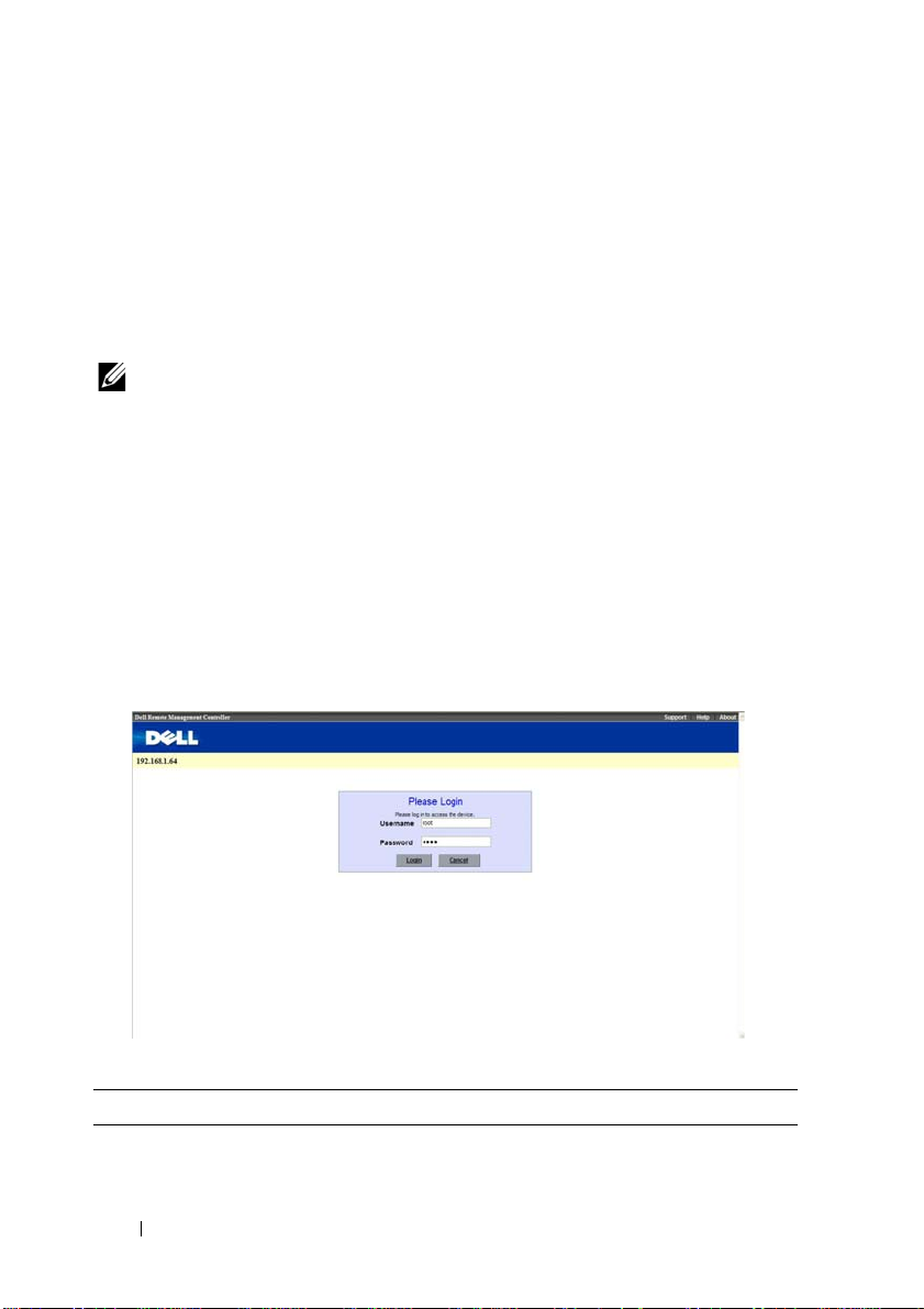
Logging in to the Web User Interface
Enter the IP address or URL (default DHCP\static IP address) into the
address bar of the web browser.
When connecting to the BMC, the login screen prompts for the username
and password. This authentication with Secure Sockets Layer (SSL)
protection prevents unauthorized intruders from gaining access to the BMC
web server. Once authentication is passed, you can manage the server by
privilege.
Table 1-1. Default User Name And Password
Field Default
User Name root
6
Page 7

Table 1-1. Default User Name And Password
Field Default
Password root
NOTE: The default username and password are in lowercase characters. It is
advised to change the root password once you have logged in.
Click the Help button on the top right corner for assistance. Click Logout to
exit.
Menu Item Description
System Information Displays the system information.
Server Health Displays the monitoring status of the
server.
Configuration Allows the user to configure the IPMI
settings.
Remote Control Allows the user to launch KVM console
and perform power control.
Maintenance Allows the user to do firmware update.
Language Allows the user to select a language
setting. (Currently, only support
English.)
7
Page 8

System Features
System Information
The System Information page enables you to view the BMC firmware version,
BIOS version, and Chassis version. Click System Information to view the
Remote Management Controller.
Table 1-2. BMC Summary
BMC Information Description
Device Power Status Current power state of the system.
Firmware Revision Dell Remote Management Controller firmware version.
Aux Firmware Revision Firmware build number.
BIOS Version BIOS version for the system.
Firmware Build Time Date the firmware was last flashed in the form:
M DD YYYY HH:MM:SS
BMC Date & Time Current date and time in the form:
W, DD M YYYY HH:MM:SS
BMC Chipset Dell Remote Management Controller type.
Chassis Type Displays the chassis type.
Chassis Version Displays the chassis version number.
MB Position Displays the current position of the mainboard within the
chassis.
8
Page 9

Component Information
The Number of CPU Socket field and the Number of Memory Slot field
display the total number of motherboard supported.
CPU Information
Including CPU ID, Status, Socket, Manufacturer, Model, and Frequency.
Memory Information
Including Memory ID, Status, Socket, Module Size, Model, and Frequency.
9
Page 10

Server Identify
The Server Identify page displays the indicator LED status. You can select a
Server Identify Operation to control the indicator LED functions.
Table 1-3. Server Identify
Item Description
Current Server Identify Displays the current server identify status is on or off.
Server Identify
Operation
Server Identify Timeout You can set the timeout value when you select the Blink
Perform Action Click to execute the selected Server Identify Operation.
Select the server identify LED operation:
• ON
• OFF
• Blink
operation. The range is between 1 to 255 seconds, but note
255s is blinking continuously.
10
Page 11

Firmware Update
Use the Firmware Update feature to upgrade to the latest firmware version.
The following data is included in the BMC firmware package:
• Compiled BMC firmware code and data
• Web-based user interface, JPEG, and other user interface data files
• Default configuration files
Updating the BMC Firmware
NOTE: Before beginning the firmware update, download the latest firmware
version and save it on your local system. During the process of firmware update, the
AC power of the managed system cannot be unplugged and the Web GUI cannot be
closed.
NOTE: Once you enter into Update Mode and choose to cancel the firmware flash
operation, the BMC must be reset. This means that you must close the Internet
browser and log back onto the BMC card before you can perform any other types of
operations.
Select the Enter Update Mode button from the Maintenance tab to put the
device in a special mode that allows firmware update. You can now follow the
instructions presented below to successfully update the card’s firmware. The
device resets if update is cancelled. The device also resets upon successful
completion of firmware update.
1
Browse to, or enter the path on your system where the firmware image file
resides.
Example:
C:\Updates\V1.0\<image_name>
The default firmware image name is s81k
XXX
.bin (whereas XXX is the
version number).
2
Select
Auto Reset BMC
if you want the BMC to auto reset after the
update.
3
BMC will not check if the Firmware image belongs to C5220 platform
when selecting
4
Click the
5
BMC will save configure settings when
Force Update
Upload Firmware
.
button.
Preserve Configuration
is selected.
11
Page 12

6
Click
Start Upgrade
The update might take several minutes. When the update is completed, a
dialog box appears.
7
Click OK to close the session and automatically log out.
8
After the BMC resets, click
.
Log In
to log in to the BMC again.
12
Page 13

Front Panel User Interface
The BMC provides control panel interface functionality including indicators
(fault, status, and ID LEDs) and buttons (power/ID).
Power Button
The power button turns the device on and off.
The power button has a deferred mechanism. When the DC is off the power button
ignores one (1) second or less activation to protect against accidental DC power on.
LEDs
BMC Heartbeat LED
The green LED provides an easy way to indicate that BMC is now enabled.
ID LED
A blinking LED indicates the Chassis Identify command has been accepted.
System Status LED
There is a dual-color LED to show the system status. The BMC turns the
LED off after all event logs are cleared.
The behavior of Status LED and ID LED is listed in Table 1-2.
Table 1-4. LED Status
LED Color Status Occurrence Note
Status LED Amber Blinking See "Blinking Fault
LED Conditions" on
page 14.
Off Normal status
Green Solid On Power On (S1/S0)The power LED status is
Off Power Off (S4/S5)
controlled by BIOS.
13
Page 14

Table 1-4. LED Status
LED Color Status Occurrence Note
ID LED Blue Off Normal status (by IPMI
Chassis Identify
command or System ID
Button)
Solid On Identify the system Turn on the ID LED.
Blinking Identify the system with
interval
Heartbeat
LED
Green Off BMC is not ready
Blinking BMC is ready
Turn off the ID LED.
1. ipmitool raw 0x00 0x04
0x00
2. ipmitool raw 0x00 0x04
0x00 0x00
1.ipmitool raw 0x00 0x04 0x3c
01
1. IPMI chassis identify
command without request
data ipmitool raw 0x00 0x04
2. IPMI chassis identify
command with only 1
parameter data ipmitool raw
0x00 0x04 0x3c (blink 60 sec)
3. IPMI chassis identify
command with 2 parameter
data ipmitool raw 0x00 0x04
0x3c 0x00 (blink 60 sec)
Table 1-5. Blinking Fault LED Conditions
Index Sensor Name Event Triggers
1 CPU Temp
Ambient Temp,
• Upper Critical Going High
• Upper Non-Critical Going High
DIMM Temp
Rear Temp 1
Rear Temp 2
Rear Temp 3
2 SLED 12V
• Upper Critical Going High
• Upper Non-Critical Going High
14
Page 15

Index Sensor Name Event Triggers
3 BMC Watchdog
•Timer expired
•Hard reset
•Power down
• Power cycle
4 Processor
•IERR
•Thermal trip
5 BMC SEL
• SEL full (909 records)
• SEL almost full (909 x 75% = 681 records)
6 Processor Hot State Asserted
7 System Event PEF action
8 PCIE Error Bus correctable error
Bus Uncorrectable error
Bus fatal
9 POST Error System firmware error
10 CPU1_DIMM A1
CPU1_DIMM A2
CPU1_DIMM A3
•Correctable error
•Uncorrectable error
• Correctable ECC error logging limit reached
CPU1_DIMM A4
11 SYS FAN 1 ~
SYS FAN 8
12 PSU 1 Status
PSU 2 Status
• Lower critical going low
• Lower non-critical going low
• Presence detected
• TEMPERATURE Failure detected
•IOUT Failure detected
•VOUT Failure detected
•FANS Failure detected
• INPUT Failure detected
13 PSU Redundancy Redundancy lost
14 Mixed MB
• Mixed MB detected
• Key Slot error detected
15
Page 16
System Information
System Information
The System Information page shows general information about the system
including Device Power Status, Firmware Revision, AuxFirmware Revision,
Firmware Build Time, BMC Chipset, BIOS Version, and Chassis Version.
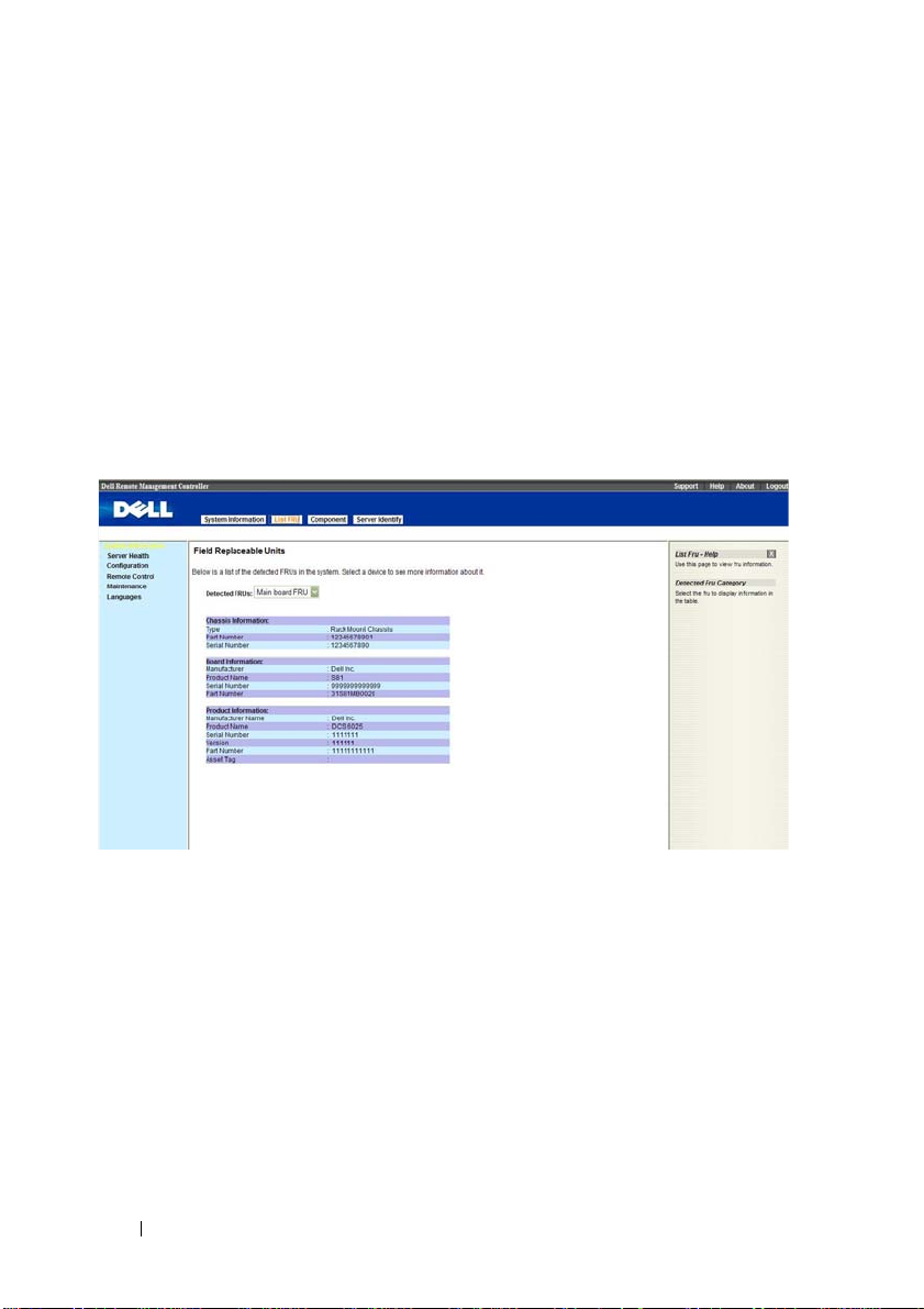
List FRU
The List FRU page shows a list of the detected Field Replaceable Units
(FRUs) in the system. Select a FRU item from the drop down list to show
more information.
16
Page 17

Component Information
The Component Information page shows a table of the components. The
components can be filtered by category and can be sorted by the column
header. The table shows the Socket, Manufacturer, and Model of each
component.The Number of CPU Socket field and the Number of Memory
Slot field display the total number of motherboard supported.
17
Page 18

Server Health
The Server Health page provides information about the server’s health such
as sensor readings and the event log. The sensor readings can be shown with
or without thresholds in the table.
Table 1-6. Server Health Options
Button Description
Sensor Readings This button allows you to view the readings from the
various sensors.
Sensor Readings with
Thresholds
Event Log This button allows you to view the event logs written to the
This button allows you to view the readings from the
various sensors, with thresholds included in the table.
event log table.
18
Page 19

Sensor Readings
The Sensor Readings page shows all sensor readings from the system.
NOTE: The sensor type category displays the full sensor (threshold-base) type only.
Table 1-7. Sensor Readings
Button Description
Name Name of the sensor.
Status Shows the current status of the sensor.
Reading The current value of the sensor.
Refresh Click to refresh the current table.
Show Thresholds Click to see the threshold value of the sensor.
19
Page 20

Sensor Readings With Thresholds
The Sensor Readings with Thresholds page shows all sensor readings and
thresholds from the system.
Table 1-8. Sensor Readings With Thresholds
Item Description
Sensor Selection Drop
Down Menu
Sensor Readings List This field shows the individual sensor’s name, reading and
Refresh Button Click to refresh the current table.
This drop-down menu allows you to select the type of
sensor readings that you want to show in the list.
• All Sensors
•Temperature Sensors
• Current Sensors
•Fan Sensors
the current status of the sensor. It also shows the following
threshold settings for every sensor.
• Low NR: lower non-recoverable
• Low CT: lower critical
• Low NC: lower non-critical
• High NC: upper non-critical
• High CT: upper critical
• High NR: upper non-recoverable
20
Page 21

Table 1-8. Sensor Readings With Thresholds
Item Description
Hide Thresholds Button Clicking Hide Thresholds button reduces the sensor
reading table and hides the various threshold settings for
every sensor.
Temperature Monitoring
The system supports the following temperature sensors.
Table 1-9. Temperature Sensors (8-Sled Chassis)
Temperature Sensor Number UNCT UCT
CPU Temp 0x44 77 82
Ambient Temp 0x40 44 47
DIMM Temp 0x4C 68 72
Rear Temp 1 0x54 46 47
Rear Temp 2 0x55 46 47
Rear Temp 3 0x56 46 47
Table 1-10. Temperature Sensors (12-Sled Chassis)
Temperature Sensor Number UNCT UCT
CPU Temp 0x44 71 76
Ambient Temp 0x40 44 47
DIMM Temp 0x4C 68 72
Rear Temp 1 0x54 46 47
Rear Temp 2 0x55 46 47
Rear Temp 3 0x56 46 47
21
Page 22

Current Monitoring
BMC supports current sensor as shown in Table 1-11. The current sensor
monitoring aims to gain the SLED power consumption for power
management used.
Table 1-11. Current Monitoring
Current Sensor Number UNCT UCT
SLED 12V 0x4E 216 252
FAN Control and Monitoring
The BMC receives all fan tachometers of the threshold base from the chassis
controller. The following is the table of the fan speed thresholds.
Table 1-12. Fan Thresholds
Fan Sensor Sensor
Number
SYS FAN 1 0x68 600 rpm 720 rpm
SYS FAN 2 0x69 600 rpm 720 rpm
SYS FAN 3 0x6A 600 rpm 720 rpm
SYS FAN 4 0x6B 600 rpm 720 rpm
SYS FAN 5 0x6C 600 rpm 720 rpm
SYS FAN 6 0x6D 600 rpm 720 rpm
SYS FAN 7 0x6E 600 rpm 720 rpm
SYS FAN 8 0x6F 600 rpm 720 rpm
LCT LNCT
22
Page 23

Event Log
The Event Log page shows the event logs from the managed system.
NOTE: If the event log belongs to the OEM SEL Record, the Sensor Type field will
display the Manufacturer ID and the Description field will display the raw data of
the OEM Defined field. Because these logs are recorded by the OS, and need to be
decoded by OS, please use the Windows Event Viewer to get further data.
Table 1-13. Event Log
Item Description
Select An Event Log
Category
Event Log You can obtain the following information for each event:
Refresh Button Use this button to refresh the event logs view.
Clear Event Log Button Click the Clear Event Log button to clear the event logs.
Select one of the following event categories:
• All Event Logs
• Sensor-Specific Events
• BIOS-Generated Events
• System Management Software Events
•Event ID
•Time Stamp
•Sensor Name
•Sensor Type
•Description
23
Page 24

Configuration
The Configuration menu allows you to access various configuration settings
including Alerts, Mouse Mode, Network, SOL, SNMP, SMTP, Users, PEF, SSL
Certification and Web Session settings.
Table 1-14. Configuration Options
Button Description
Alerts Button This button takes you to the Alert list page where you can
add, edit or remove alert destinations.
Mouse Mode Button This button takes you to the Mouse Mode settings page
where you can view the current setting and/or change the
mode of your pointing device to/from either Relative or
Absolute.
Network Button This button takes you to the Network settings page where
you can view the MAC address or change network settings,
including the dynamic and static IP assignment.
SOL This buttons takes you to the Serial Over Lan settings
page, where you can enable SOL and channel privilege
level limits.
SNMP This button takes you to the SNMP community string
page for the SNMP trap server where you can modify the
string and save the settings.
24
Page 25

Table 1-14. Configuration Options
Button Description
SMTP This button takes you to the SMTP settings page where
you can configure the SMTP mail server.
Users This button takes you to the user list page where you can
add, edit or remove users.
PEF This button takes you to the PEF list page where you can
configure PEF settings including Event Filter Action, Alert
Policy Number, Sensor Type, and Event Trigger.
SSL Certificate This button takes you to the SSL certificate page where
you can upload an SSL Certificate.
Web Session This button takes you to the Web session configuration
page where you can modify the web session timeout value.
25
Page 26

Alerts
When BMC sends a platform event, such as an environment warning or a
component failure, an alert message may be sent to one or more email
addresses / IP addresses. On the Alerts page, you can configure alert
destinations. To delete an alert, select it and press Delete. To create a new
alert, select a destination address that has not been configured, yet, from the
alert table entry and click Modify. To send a test alert, select the alert from
the list and click the Send Test Alert button.
Table 1-15. Alerts
Item Description
Alert Policy #
Destination Address Lists the SNMP trap destination IP address or email
Modify Button This button takes you to the Modify Alerts page. You can
Send Test Alert Button Select an alert entry and press Send Test Alert to send a
Delete Button Select an alert configuration entry and press Delete to
Lists all alert entries.
address for the listed entries.
add a new alert configuration entry or modify an existing
entry.
test alert.
delete the entry.
26
Page 27

Modify Alert
Table 1-16. Modify Alerts
Items Description
Alert Type You can select the way an alert is sent when it is triggered by an
event.
•SNMP Trap
•Email
NOTE: If you select SNMP Trap as the Alert Type, Email Address,
Subject, Message is disabled. If you select Email as the Alert
Type, Destination IP is disabled.
Destination IP Type the SNMP destination IP address into this field, when
you select SNMP Trap as the Alert Type.
Email Address Type the Email address into this field, when you select Email as
the Alert Type.
Subject Type a Subject into this field, when you select Email as the
Alert Type.
Message Type a Message into this field, when you select Email as the
Alert Type.
Save Use this button to save your settings.
Cancel Use this button to cancel your action.
27
Page 28

Mouse Mode
On the Mouse Mode page, you can configure the mouse mode options.
Table 1-17. Mouse Mode
Item Description
Current Mouse Mode Absolute or Relative.
NOTE: Both Absolute and Relative modes enable you to see
two mouse cursors where, the redirected host mouse cursor
and the actual local mouse cursor. When the single cursor
checkbox is selected, only the redirect mouse cursor is
visible.
Set Mode to Absolute
Option
Set Mode to Relative
Option
Save Button Use this button to make the settings active.
Select this option to select mouse mode to Absolute,
depending upon your system.
Select this option to select mouse mode to Relative,
depending upon your system. If you select the single
mouse checkbox, it locks the local mouse cursor inside the
redirected window and the user has to press <Alt+M> to
unlock and stop mouse redirection. Here <Alt+M> is
basically used to start or stop mouse redirection.
IPMI is an OS-independent platform, and KVM support is an added feature
for IPMI. For your mouse to function properly, please configure the mouse
mode settings according to the mouse is absolute coordinates or relative
28
Page 29

coordinates on your host server. For example, it is recommended to use
absolute / relative mouse mode when your host server is running in Windows
or Linux.
NOTE: When you choose the relative mouse mode. The redirected host mouse
cursor may not overlap with the actual local mouse cursor (depending on the
mouse cursor acceleration setting of the host OS). If this situation occurs, it is
recommended to select the single cursor checkbox.
Network
The Network page allows you to view and modify the network settings. Select
whether to obtain an IP address automatically or manually configure one.
NOTE: To change any of the settings on the Network Configuration page, you must
have permission to configure the BMC. Do not do network configuring when the
server is in BIOS mode; the network configuration may be conflict with the BIOS.
Table 1-18. Network
Item Description
MAC Address This field shows the MAC address.
Obtain an IP address
automatically (use DHCP)
This option allows the BMC’s IP to be configured by a DHCP
server (dynamically).
29
Page 30

Table 1-18. Network
Item Description
Use the following IP
address
IP Address This field allows you to set the BMC’s IP address.
Subnet Mask This field allows you to set the Subnet Mask.
Default Gateway This field allows you to set the BMC’s Gateway access address.
Obtain DNS IP address
automatically
Use the following DNS IP
address
Primary DNS Server Specify the IP address of the preferred DNS server.
Secondary DNS Server Specify the alternative IP address to be used when the preferred
Enable DNS Register BMC
Host Name
DNS BMC Host Name Specifies the DNS BMC host name.
Enable DNS Domain
Name (use DHCP)
DNS Domain Name Specified the DNS domain name.
Save Button Use this button to save your settings.
This option allows you to configure a static IP. The IP Address,
Subnet Mask, and Gateway fields become editable when this
option is selected.
This option allows the DNS IP to be configured by a DHCP
server (dynamically).
This option allows you to configure the DNS IP address with a
static IP. The Primary and Secondary DNS Server will become
editable when this option is selected.
DNS server is not available.
When checked, it will register with the Domain Name Server.
DNS BMC Host Name field will become read-only when this
option is selected.
Enable / disable acquisition of DNS Domain Name from DHCP
server. DNS Domain Name field will become read-only when this
option is selected.
NOTE: If you configure the IP address with a static IP, you can’t get the DNS IP
address from the DHCP server.
NOTE: If you want to update the DNS information with the DNS server, you must
select “Obtain an IP address automatically” to get IP address dynamically. And the
DNS server IP will provide by the DHCP server.
30
Page 31

VLAN Settings
Table 1-19. VLAN Settings
Items Description
Enable VLAN Enable / disable VLAN function.
Note: If enabled, BMC will only accept packets for this channel
if they have 802.1q fields and their VLAN ID matches the
VLAN ID field.
VLAN ID Identification for VLAN Interface. The range of VLAN ID is
from 2 to 4094.
VLAN Priority The range of VLAN Priority is from 0 to 7 (7 is the highest
priority). This field can be set only if user login web page via
VLAN interface.
Save Use this button to save your settings.
Cancel Use this button to cancel your action, and back to network
settings page.
31
Page 32

SOL
The SOL page allows you to configure the Serial Over LAN settings, select or
change pertinent values for each attribute and save any changes.
Table 1-20. Serial Over LAN Settings
Item Description
Enable Serial Over LAN Check this field to enable (checked) or disable (unchecked) Serial
Over LAN.
Channel Privilege Level
Limit
Save Use this button to save any settings changes.
Advanced SOL Settings Use this button to enter the Advanced SOL page.
Select the IPMI Serial Over LAN (minimum) user privileges:
• Administrator
•Operator
•User
32
Page 33

SOL Advanced Settings
Table 1-21. Advanced SOL settings
Item Description
Character
Accumulate Interval
Character Send
Threshold
Save Use this button to save your advanced settings.
Cancel Use this button to back to SOL page.
The amount of time that the BMC will wait before
transmitting a partial SOL character data package. 1-based
5ms increments. This value must be less than 255.
The BMC will send an SOL character data package containing
the characters as soon as this number of characters (of greater)
has been accepted. 1-based units. This value must be less than
255.
33
Page 34

SNMP
The SNMP page displays the community string page for the SNMP trap server. You
can modify the community string and save the new settings.
Table 1-22. SNMP
Item Description
Community String In the field, enter the SNMP community string for the
destination IP address.
Save Button Use this button to save the new settings.
34
Page 35

SMTP
The SMTP page allows you to configure the SMTP mail server.
Table 1-23. SMTP
Item Description
Mail Server IP This field allows you to configure the IP address of the SMTP
mail server.
Save Button Use this button to save your settings.
35
Page 36

Users
The Users page allows you to view the current list of user for the server. If you
would like to delete or modify a user, select their name in the list and click
Delete User or Modify User. To add a new user, select an un-configured slot
and select Add User
NOTE: Only user accounts over administrative rights are allowed to add, edit and
delete users, but administrative level privileges still can’t delete root, anonymous
and itself. If a new user is given administrative privileges, permissions are
automatically granted for all interfaces.
Item Description
UserID Column This column shows the ID number used in association
with the User Name.
User Name Column This column shows a list of all users who are able to access
this BMC.
NOTE: The default administrator is root. It is prudent for you
to change the root password.
Network Privilege
Column
Add User Button Use this button to add a new user. Select an open field
This column shows the network rights associated with the
account.
first.
36
Page 37

Item Description
Modify User Button Use this button to modify an existing user. Select a user
first.
Delete User Button Use this button to delete an existing user. Select a user
first.
Add New User
Add New User
Item Description
User Name Enter a user name in the user name field. Your user name
must be a string of 4 to 15 alpha-numeric characters.User
names are case-sensitive and must start with an
alphabetical character.
Password Enter a password in the Password field. Your password must
be a string of 8 to 20 alpha-numeric characters.
NOTE: Use a combination of alphanumeric and special
characters for better security. The password is casesensitive.
Confirm Password Confirm your password by entering your password again in
the Confirm Password field.
37
Page 38

Add New User
Item Description
Network Privileges Drop
Down Menu
Add Button Use this button to add the new user.
Cancel Button Use this button to cancel this action.
Assign network permissions and access rights to any of the
following:
•User
•Operator
• Administrator
•OEM Proprietary
•No Access
38
Page 39

Modify User
Table 1-24. Modify User
Item Description
User Name This field contains the user name being modified. This field
cannot be modified.
Change Password Box Select this box to change the password.
Password Enter a password in the Password field. Your password must be
a string of 8 to 20 alpha-numeric characters.
NOTE: Use a combination of alphanumeric and special
characters for better security. The password is case-sensitive.
Confirm Password Confirm your password by entering your password again in the
Confirm Password field.
Network Privileges
Drop Down Menu
Modify Button Use this button to update the user account.
Cancel Button Use this button to cancel this action.
Modify network permissions and access rights to any of the
following:
•User
•Operator
• Administrator
•OEM Proprietary
•No Access
39
Page 40

PEF
The PEF page allows you to configure the platform event filters. The
Platform Event Filters List displays the actions that will execute when an
event occurs. An event occurs when the status of a system element is outside
a set limit. You can select a PEF and press the Modify button to configure it.
Or you can press Delete to remove it.
Table 1-25. PEF
Item Description
PEF# Number of PEF configuration entry. There are 40 PEF
configuration entries in the system.
Event Filter Action Specify the corresponding action for a PEF triggered event.
Sensor Type Displays the sensor type.
Sensor Num Displays the sensor number.
Event Trigger Show the threshold type to cause the event occurs.
40
Page 41

Modify PEF
Change the attributes, and click the Save button to save any changes. If you
want to cancel this action, click the Cancel button to return to PEF list page.
Table 1-26. Modify PEF
Item Description
Event Filter
Action
Alert Policy
Num
Sensor Type
Sensor Num Enter the sensor number.
Event Trigger Choose the event trigger type.
Filter
Enable/Disable
Check/uncheck the Alert box to enable/disable alert occurs. You can select one
of power operation. If event occurs, the power action will perform.
•No Power Action
•Power Down
• Reset
•Power Cycle
Choose the alert policy number of the Alerts List.
Select the sensor type.
• Any: choose all trigger type events
• Select: choose a single trigger type event
Check/uncheck this box to enable/disable this filter.
41
Page 42

SSL Certificate
The SSL Certificate page allows you upload a new SSL certificate.
The SSL page does not support encryption of private keys, for example: DES, AES,
etc. Upload unencrypted private key to access support.
Table 1-27. PEF
Item Description
Default Certificate Displays the time of creation of the default certificate.
Default Privacy Key Displays the time of creation of the existing privacy key.
New SSL Certificate Use the Browse button to select a new certificate to upload.
Upload Button Use this button to upload the previously selected certificate.
The Certificate file name should end with the file suffix
.pem
or
.crt
you click on the Upload button, the new SSL certificate will replace the
existing certificate.
42
. After
Page 43

Uploading Private Key
Table 1-28. SSL Private Key Upload web page
Item Description
Default Certificate Displays the creating time of the existing certificate.
Default Privacy Key Display the creating time of the existing privacy key.
New Private Key Click to choose the new Private Key that you want to upload.
Upload Click to start upload Private Key.
The Private Key file name should end with
.pem
or
.key
. After you upload the
new Private Key, the web server will restart. You must close this browser
session and open a new browser session to reconnect to the device.
43
Page 44

Web Session
The Web Session page allows you to change web session time out values. The
default value is 300 seconds. If you don't active web within 300 seconds, the
web session will time out and you must login again.
Table 1-29. PEF
Item Description
Never Time Out This option allows the web session never time out.
Setting Time Out
Seconds
Time Out Specify the time out value.
Save Use this button to save your settings.
This option allows you to configure the web session time out
value. The Time Out field will become editable when this
option is selected.
NOTE: The Time Out value must be between 30 to 7200 seconds.
The default value is 300 seconds.
44
Page 45

Remote Control
The Remote Control menu allows you to initiate Console Redirection and to
view the Power Control options.
NOTE: The Console Redirection page is ONLY enabled in the AST2050 BMC
chipset.
Console Redirection
The Console Redirection page enables you to use the display, mouse, and
keyboard on the local management station to control the corresponding
devices on a remote managed system. Click on Java Console to launch the
Java-based remote console.
NOTE: Before you can use the Console Redirection feature, your browser must
have the JRE installed in your operating system. The umber of sessions allowed is
two.
NOTE: The recommended display resolution on the management station (or client)
is at least 1024 x 768 pixels at 60 Hz with 32 bit color. You cannot view the console in
full screen mode if your monitor resolution is less than the minimum.
NOTE: If Console Redirection is launched and not closed, the web session timeout
function is closed.
45
Page 46

Table 1-30. Console Redirection, Java Console Launch
Item Description
Java Console Use this button to launch the redirection console using
Java viewer.
Table 1-31. Remote Console Shortcut Key Combinations
Keystroke Description
<ALT+S> Start Console Redirection
<ALT+T> Stop Console Redirection
<ALT+R> Restart Console Redirection
<ALT+F> Toggle Full Screen Mode
<ALT+M> Synchronize Mouse
<ALT+A> Hold/Unhold Right <ALT> Key
<ALT+B> Hold/Unhold Left <ALT> Key
<ALT+L> Hold/Unhold Right <CTRL> Key
<ALT+N> Hold/Unhold Left <CTRL> Key
<ALT+D> Generate <CTRL>, <ALT>, + <DEL>
<ALT+E> Start CD-ROM Drive Redirection
Table 1-32. Console Redirection Window: Keyboard
Menu Item Description
Hold Right Ctrl Key This menu item can be used to act as the right-side
<CTRL> key when in Console Redirection.
Hold Right Alt Key This menu item can be used to act as the right-side
<ALT> key when in Console Redirection.
Hold Left Ctrl Key This menu item can be used to act as the left-side
<CTRL> key when in Console Redirection.
Hold Left Alt Key This menu item can be used to act as the left-side <ALT>
key when in Console Redirection.
46
Page 47

Table 1-32. Console Redirection Window: Keyboard
Menu Item Description
Left Windows Key This menu item can be used to act as the left-side
<WIN> key when in Console Redirection. You can also
decide how the key should be pressed:
•Hold Down
• Press and Release
Right Windows Key This menu item can be used to act as the right-side
<WIN> key when in Console Redirection. You can also
decide how the key should be pressed:
•Hold Down
• Press and Release
<Alt+Ctrl+Del> This menu item can be used to act as if you pressed the
<CTRL>, <ALT> and <DEL> keys down
simultaneously on the server that you are redirecting.
Table 1-33. Console Redirection Window: Mouse
Menu Item Description
Sync Cursor This menu item can be used to synchronize or un-
synchronize the mouse cursor.
Show Cursor This menu item can be used to show or hide the local
mouse cursor on the remote client system.
47
Page 48

Table 1-34. Console Redirection Window: Options
Item Description
Bandwidth The bandwidth usage option allows you to adjust the
bandwidth. You can select one of the following:
•Auto Detect
•256 Kbps
•512 Kbps
• 1 Mbps
•10 Mbps
•100 Mbps (Default Setting)
KB/Mouse Encryption This option allows you to encrypt keyboard inputs and
mouse movements sent between the connections.
Table 1-35. Console Redirection Window: Options
Item Description
Video Settings Hide the hardware cursor, and transmit video deltas only.
Video Engine
Configuration Settings
• Compression Mode: YUV compression, where Y is
luminance and UV is chrominance.
• DCT Quantization Table: number to control DCT
quality.
Table 1-36. Console Redirection Window: Device
Menu Item Description
Redirect CDROM This menu item can be used to start or stop the redirection
of a physical DVD/CD-ROM drive.
Redirect ISO This menu item can be used to start or stop the redirection
of a DVD/CD ISO image.
Redirect Floppy/USB
Key
This menu item can be used to start or stop the redirection
of a physical floppy/USB key drive.
48
Page 49

Table 1-36. Console Redirection Window: Device
Menu Item Description
Redirect Floppy/USB
Key Image
Table 1-37. Console Redirection Window: Help
Menu Item Description
About JViewer Shows the copyright and version information.
This menu item can be used to start or stop the redirection
of a floppy/USB key image, instead of a physical driver.
Power Control
The Power Control page allows you to view and control the power of your
server. Select one of the options listed in the following table to execute on
your server. You are asked to confirm your choice. Upon confirmation, the
command is executed and you are informed of the status.
Table 1-38. Power Control and Status
Menu Item Description
Reset Server Option Select this option to reset the server.
49
Page 50

Table 1-38. Power Control and Status
Menu Item Description
Power Off Server Immediate Option
Power Off Server Orderly Shutdown
Option
Power On Server Option Select this option to power up the server.
Power Cycle Server
Option
Perform Action Button Select this button to execute the option selected.
Select this option to power down the server immediately.
Select this option to power down the server gracefully.
Select this option to power cycle the server.
50
Page 51

Maintenance
The Maintenance menu allows you to perform maintenance tasks on the
device including the Firmware Update. Refer to "Firmware Update" on
page 11.
Languages
The Languages menu allows you to select the language for the web
application. Select the language from the drop down list and click Apply.
NOTE: The web interface needs to reload for the change to take effect.
51
Page 52

IPMI 1.5 / 2.0 Command Support List
Table 1-39. IPMI Device Global Commands
Command NetFn CMD O/M Supported
Get Device ID App 01h M Yes
Cold Reset App 02h O Yes
Warm Reset App 03h O No
Get Self Test Results App 04h M Yes
Manufacture Test On App 05h O Yes
Set ACPI Power State App 06h O Yes
Get ACPI Power State App 07h O Yes
Get Device GUID App 08h O Yes
Broadcast Command:
Broadcast ‘Get Device ID’ App 01h M No
Table 1-40. BMC Device and Messaging Commands
Command NetFn CMD O/M Supported
Set BMC Global Enables App 2Eh M Yes
Get BMC Global Enables App 2Fh M Yes
Clear Message Buffer Flags App 30h M Yes
Get Message Buffer Flags App 31h M Yes
Enable Message Channel
Receive
Get Message App 33h M Yes
Send Message App 34h M Yes
Read Event Message Buffer App 35h O Yes
Get BT Interface Capabilities App 36h M No
Get System GUID App 37h O Yes
App 32h O Yes
52
Page 53

Table 1-40. BMC Device and Messaging Commands
Command NetFn CMD O/M Supported
Get Channel Authentication
Capabilities
Get Session Challenge App 39h O Yes
Activate Session Command App 3Ah O Yes
Set Session Privilege Level
Command
Close Session App 3Ch O Yes
Get Session Information App 3Dh O Yes
Get Authentication Code
Command
Set Channel Access Commands App 40h O Yes
Get Channel Access Commands App 41h O Yes
Get Channel Info Command App 42h O Yes
Set User Access Commands App 43h O Yes
Get User Access Commands App 44h O Yes
Set User Name Commands App 45h O Yes
Get User Name Commands App 46h O Yes
Set User Password Commands App 47h O Yes
Active Payload Command App 48h O Yes
Deactivate Payload Command App 49h O Yes
Get Payload Activation Status App 4Ah O Yes
Get Payload Instance Info
Command
Set User Payload Access App 4Ch O Yes
Get User Payload Access App 4Dh O Yes
Get Channel Payload Support App 4Eh O Yes
Get Channel Payload Version App 4Fh O Yes
Get Channel OEM Payload Info App 50h O Yes
App 38h O Yes
App 3Bh O Yes
App 3Fh O Yes
App 4Bh O Yes
53
Page 54

Table 1-40. BMC Device and Messaging Commands
Command NetFn CMD O/M Supported
Master Write-Read I2C App 52h M Yes
Get Channel Cipher Suites App 54h O Yes
Suspend/Resume Payload
Encryption
Set Channel Security Keys App 56h O Yes
Get System Interface
Capabilities
Table 1-41. BMC Watchdog Timer Commands
Command NetFn CMD O/M Supported
Reset Watchdog Timer App 22h M Yes
Set Watchdog Timer App 24h M Yes
Get Watchdog Timer App 25h M Yes
Table 1-42. Chassis Commands
Command NetFn CMD O/M Supported
Get Chassis Capabilities Chassis 00h M Yes
Get Chassis Status Chassis 01h M Yes
Chassis Control Chassis 02h M Yes
Chassis Reset Chassis 03h O No
Chassis Identify Chassis 04h O Yes
Set Chassis Capabilities Chassis 05h O Yes
Set Power Restore Policy Chassis 06h O Yes
Get System Reset Cause Chassis 07h O[1] Yes
Set System Boot Options Chassis 08h O Yes
Get System Boot Options Chassis 09h O Yes
Set Front Panel Button Enable Chassis 0Ah O Yes
Set Power Cycle Interval Chassis 0Bh O Yes
App 55h O Yes
App 57h O Yes
54
Page 55

Table 1-42. Chassis Commands
Command NetFn CMD O/M Supported
Get POH Counter Chassis 0Fh O Yes
[1] Optional portion of Get System Reset Cause is not support.
Table 1-43. Event Commands
Command NetFn CMD O/M Supported
Even
Receiver
Set Event Receiver S/E 00h M M Yes
Get Event Receiver S/E 01h M M Yes
Platform Event S/E 02h M M Yes
Table 1-44. SEL Commands
Command NetFn CMD O/M Supported
Get SEL Info Storage 40h M Yes
Get SEL Allocation Info Storage 41h O Yes
Reserve SEL Storage 42h O Yes
Get SEL Entry Storage 43h M Yes
Add SEL Entry Storage 44h M Yes
Partial Add SEL Entry Storage 45h M Yes
Delete SEL Entry Storage 46h O Yes
Clear SEL Storage 47h M Yes
Get SEL Time Storage 48h M Yes
Set SEL Time Storage 49h M Yes
Get Auxiliary Log Status Storage 5Ah O No
Set Auxiliary Log Status Storage 5Bh O No
Event
Generator
NOTE: Support for Partial Add SEL is not required when Add SEL is supported.
55
Page 56

Table 1-45. SDR Repository Commands
Command NetFn CMD O/M Supported
Get SDR Repository Info Storage 20h M Yes
Get SDR Repository Allocation
Info
Reserve SDR Repository Storage 22h M Yes
Get SDR Storage 23h M Yes
Add SDR Storage 24h M Yes
Partial ADD SDR Storage 25h M Yes
Delete SDR Storage 26h O No
Clear SDR Repository Storage 27h M Yes
Get SDR Repository Time Storage 28h O Yes
Set SDR Repository Time Storage 29h O Yes
Enter SDR Repository Update
Mode
Exit SDR Repository Update
Mode
Run Initialization Agent Storage 2Ch O Yes
Storage 21h O Yes
Storage 2Ah O No
Storage 2Bh O No
Table 1-46. FRU Inventory Device Commands
Command NetFn CMD O/M Supported
Get FRU Inventory Area Info Storage 10h M Yes
Read FRU Inventory Data Storage 11h M Yes
Write FRU Inventory Data Storage 12h M Yes
56
Page 57

Table 1-47. Sensory Device Commands
Command NetFn CMD O/M Supported
Get Device SDR Info S/E 20h O No
Get Device SDR S/E 21h O No
Reserve Device SDR Repository S/E 22h O No
Get Sensor Reading Factors S/E 23h O Yes
Set Sensor Hysteresis S/E 24h O Yes
Get Sensor Hysteresis S/E 25h O Yes
Set Sensor Threshold S/E 26h O Yes
Get Sensor Threshold S/E 27h O Yes
Set Sensor Event Enable S/E 28h O Yes
Get Sensor Event Enable S/E 29h O Yes
Re-arm Sensor Events S/E 2Ah O Yes
Get Sensor Event Status S/E 2Bh O Yes
Get Sensor Reading S/E 2Dh M Yes
Set Sensor Type S/E 2Eh O No
Get Sensor Type S/E 2Fh O No
Set Sensor Reading and Event
Status
S/E 30h M Yes
Table 1-48. LAN Commands
Command NetFn CMD O/M Supported
Set LAN Configuration
Parameters
Get LAN Configuration
Parameters
Suspend BMC ARP Transport 03h O Yes
Get IP/UDP/RMCP Statistics Transport 04h O No
Transport 01h M Yes
Transport 02h M Yes
NOTE: LAN parameter from 192 to 255 is reserved for OEM parameters.
57
Page 58

Table 1-48. LAN Commands
Command NetFn CMD O/M Supported
NOTE: Parameter 192 is used for DHCP Retry by DCS requirement.
Table 1-49. SOL Command
Command NetFn CMD O/M Supported
SOL Activating Transport 20h O No
Set SOL Configuration Parameters Transport 21h O Yes
Get SOL Configuration
Par ameters
Table 1-50. PEF/PET Alerting Commands
Command NetFn CMD O/M Supported
Get PEF Capabilities S/E 10h M Yes
Arm PEF Postpone Timer S/E 11h M Yes
Set PEF Configuration
Par ameters
Get PEF Configuration
Par ameters
Set Last Processed Event ID S/E 14h M Yes
Get Last Processed Event ID S/E 15h M Yes
Alert Immediate S/E 16h O Yes
PET Acknowledge S/E 17h O Yes
Transport 22h O Yes
S/E 12h M Yes
S/E 13h M Yes
58
Page 59

59
Page 60

60
 Loading...