

Dell C300 Installation Manual

Installing and Maintaining
the C300 System

Notes, Cautions, and Warnings
NOTE: A NOTE indicates important information that helps you make better use of your computer.
CAUTION: A CAUTION indicates potential damage to hardware or loss of data if instructions are not
followed.
WARNING: A WARNING indicates a potentia for property damage, personal injury, or death.
Information in this publication is subject to change without notice.
© 2013 Dell Networking. All rights reserved.
Reproduction of these materials in any manner whatsoever without the written permission of Dell Inc. is strictly forbidden.
Trademarks used in this text: Dell™, the DELL logo, Dell Precision™, OptiPlex™, Latitude™, PowerEdge™, PowerVault™,
PowerConnect™, OpenManage™, EqualLogic™, KACE™, FlexAddress™ and Vostro™ are trademarks of Dell Inc. Intel
®
Xeon
, Core™ and Celeron® are registered trademarks of Intel Corporation in the U.S. and other countries. AMD® is a registered trademark
and AMD Opteron™, AMD Phenom™, and AMD Sempron™ are trademarks of Advanced Micro Devices, Inc. Microsoft
Windows Server
States and/or other countries. Red Hat Enterprise Linux
and/or other countries. Novell
®
Oracle
is a registered trademark of Oracle Corporation and/or its affiliates. Citrix®, Xen®, XenServer® and XenMotion® are either registered
trademarks or trademarks of Citrix Systems, Inc. in the United States and/or other countries. VMware
and vSphere
®
, MS-DOS® and Windows Vista® are either trademarks or registered trademarks of Microsoft Corporation in the United
®
is a registered trademark and SUSE ™ is a trademark of Novell Inc. in the United States and other countries.
®
are registered trademarks or trademarks of VMWare, Inc. in the United States or other countries.
®
and Enterprise Linux® are registered trademarks of Red Hat, Inc. in the United States
®
, Virtual SMP®, vMotion®, vCenter®,
®
, Pentium®,
®
, Windows®,
Other trademarks and trade names may be used in this publication to refer to either the entities claiming the marks and names or their products.
Dell Inc. disclaims any proprietary interest in trademarks and trade names other than its own.
November 2013

Contents
1 About this Guide
Information Symbols and Warnings . . . . . . . . . . . . . . . . . . . . . . . . . . . . . . . . . . . . . . 7
Related Documents. . . . . . . . . . . . . . . . . . . . . . . . . . . . . . . . . . . . . . . . . . . . . . . . . . . 9
2 Overview
C300 System Installation Process . . . . . . . . . . . . . . . . . . . . . . . . . . . . . . . . . . . . . . 12
3 Preparing the Site
Site Selection Criteria . . . . . . . . . . . . . . . . . . . . . . . . . . . . . . . . . . . . . . . . . . . . . . . . 13
Rack Mounting . . . . . . . . . . . . . . . . . . . . . . . . . . . . . . . . . . . . . . . . . . . . . . . . . . . . . 14
Requirements . . . . . . . . . . . . . . . . . . . . . . . . . . . . . . . . . . . . . . . . . . . . . . . . . . . . . . 14
Shipping and Storing Components . . . . . . . . . . . . . . . . . . . . . . . . . . . . . . . . . . . . . . 15
4 Installing C300 Fan Tray
Removing the Fan Tray. . . . . . . . . . . . . . . . . . . . . . . . . . . . . . . . . . . . . . . . . . . . . . . 18
Fan Speed . . . . . . . . . . . . . . . . . . . . . . . . . . . . . . . . . . . . . . . . . . . . . . . . . . . . . 18
5 Installing RPMs and Line Cards
Route Processor Modules. . . . . . . . . . . . . . . . . . . . . . . . . . . . . . . . . . . . . . . . . . . . . 19
RPM Label and LEDs . . . . . . . . . . . . . . . . . . . . . . . . . . . . . . . . . . . . . . . . . . . . 19
Line Cards. . . . . . . . . . . . . . . . . . . . . . . . . . . . . . . . . . . . . . . . . . . . . . . . . . . . . . . . . 20
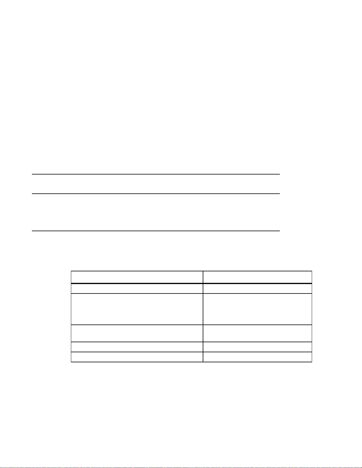
Blank Panels. . . . . . . . . . . . . . . . . . . . . . . . . . . . . . . . . . . . . . . . . . . . . . . . . . . . . . . 20
Installing the RPMs and Line Cards . . . . . . . . . . . . . . . . . . . . . . . . . . . . . . . . . . . . . 20
6 RPM Cables
Connecting the Console Port . . . . . . . . . . . . . . . . . . . . . . . . . . . . . . . . . . . . . . . . . . 25
Cable and Adapter Pin Assignments . . . . . . . . . . . . . . . . . . . . . . . . . . . . . . . . . . . . 25
Accessing the Console with a DB-9 Adapter . . . . . . . . . . . . . . . . . . . . . . . . . . . . . . 26
Accessing the Console with a DB-25 Adapter . . . . . . . . . . . . . . . . . . . . . . . . . . . . . 26
7 Installing AC Power Supplies
Installing the AC Power Supply. . . . . . . . . . . . . . . . . . . . . . . . . . . . . . . . . . . . . . . . . 32
Power Cord Requirements. . . . . . . . . . . . . . . . . . . . . . . . . . . . . . . . . . . . . . . . . 32
Power Over Ethernet (PoE) . . . . . . . . . . . . . . . . . . . . . . . . . . . . . . . . . . . . . . . . . . . 32
Power Over Ethernet Plus (PoE+) . . . . . . . . . . . . . . . . . . . . . . . . . . . . . . . . . . . . . . 33
Contents | 3

8 Installing DC Power Entry Modules
Recommended Normal Operating Conditions . . . . . . . . . . . . . . . . . . . . . . . . . . . . . 35
Redundancy . . . . . . . . . . . . . . . . . . . . . . . . . . . . . . . . . . . . . . . . . . . . . . . . . . . . . . . 35
Cable and Connector Requirements. . . . . . . . . . . . . . . . . . . . . . . . . . . . . . . . . . . . . 35
Installing a DC PEM . . . . . . . . . . . . . . . . . . . . . . . . . . . . . . . . . . . . . . . . . . . . . . . . . 36
Status LED . . . . . . . . . . . . . . . . . . . . . . . . . . . . . . . . . . . . . . . . . . . . . . . . . . . . . . . . 39
Removing a DC PEM . . . . . . . . . . . . . . . . . . . . . . . . . . . . . . . . . . . . . . . . . . . . . . . . 39
9 Powering Up
Supplying . . . . . . . . . . . . . . . . . . . . . . . . . . . . . . . . . . . . . . . . . . . . . . . . . . . . . . . . . 42
www.dell.com | support.dell.com
Booting from the BOOT_USER Prompt . . . . . . . . . . . . . . . . . . . . . . . . . . . . . . . . . . 43
10 Removing and Replacing Components
Removing and Replacing the Fan Tray. . . . . . . . . . . . . . . . . . . . . . . . . . . . . . . . . . . 45
Removing and Replacing Power Supply Units . . . . . . . . . . . . . . . . . . . . . . . . . . . . . 46
Removing and Replacing a Line Card . . . . . . . . . . . . . . . . . . . . . . . . . . . . . . . . . . . 47
11 Installing the Chassis
Safety Considerations. . . . . . . . . . . . . . . . . . . . . . . . . . . . . . . . . . . . . . . . . . . . . . . . 51
Installing the Chassis into an Equipment Rack. . . . . . . . . . . . . . . . . . . . . . . . . . . . . 51
12 System Boot
Booting from the BOOT_USER Prompt . . . . . . . . . . . . . . . . . . . . . . . . . . . . . . . . . . 55
13 The Compact Flash Card
Inserting the Compact Flash Card . . . . . . . . . . . . . . . . . . . . . . . . . . . . . . . . . . . . . . 59
Removing the Compact Flash Card . . . . . . . . . . . . . . . . . . . . . . . . . . . . . . . . . . . . . 59
Formatting the Compact Flash Card. . . . . . . . . . . . . . . . . . . . . . . . . . . . . . . . . . . . . 60
A Alarms
AC Supplies and Alarms. . . . . . . . . . . . . . . . . . . . . . . . . . . . . . . . . . . . . . . . . . . . . . 62
B System Specifications
Physical Design. . . . . . . . . . . . . . . . . . . . . . . . . . . . . . . . . . . . . . . . . . . . . . . . . . . . . 63
Chassis Dimensions . . . . . . . . . . . . . . . . . . . . . . . . . . . . . . . . . . . . . . . . . . . . . 63
Component Dimensions . . . . . . . . . . . . . . . . . . . . . . . . . . . . . . . . . . . . . . . . . . 64
System Specifications . . . . . . . . . . . . . . . . . . . . . . . . . . . . . . . . . . . . . . . . . . . . 64
Component Power Requirements . . . . . . . . . . . . . . . . . . . . . . . . . . . . . . . . . . . 65
Agency Compliance. . . . . . . . . . . . . . . . . . . . . . . . . . . . . . . . . . . . . . . . . . . . . . 66
Safety Standards and Compliance Agency Certifications. . . . . . . . . . . . . . . . . . . . . 67
4 | Contents

Electromagnetic Compatibility (EMC) . . . . . . . . . . . . . . . . . . . . . . . . . . . . . . . . 68
Product Recycling and Disposal . . . . . . . . . . . . . . . . . . . . . . . . . . . . . . . . . . . . 68
C Contacting Technical Support
The iSupport Website . . . . . . . . . . . . . . . . . . . . . . . . . . . . . . . . . . . . . . . . . . . . . . . . 71
Accessing iSupport Services . . . . . . . . . . . . . . . . . . . . . . . . . . . . . . . . . . . . . . . 71
Contacting the Technical Assistance Center . . . . . . . . . . . . . . . . . . . . . . . . . . . . . . 71
Locating Serial Numbers . . . . . . . . . . . . . . . . . . . . . . . . . . . . . . . . . . . . . . . . . . 72
Requesting a Hardware Replacement . . . . . . . . . . . . . . . . . . . . . . . . . . . . . . . . . . . 72
Contents | 5

www.dell.com | support.dell.com
6 | Contents
1
About this Guide
This guide provides site preparation recommendations and instructions for installing the Dell Networking
C300 chassis, fan tray, power supply units (supplies), route processor modules (RPMs), and line cards.
The C300 system is packaged with all of the necessary components, including slot blanks for RPMs,
power supplies, and line cards.
Information Symbols and Warnings
The following graphic symbols are used in this document to bring attention to hazards that exist when
handling the C300 and its components. Please read these alerts and heed their warnings and cautions.
Table 1-1
Table 1-1. Information Symbols
Symbol Warning Description
describes symbols contained in this guide.
Note This symbol informs you of important operational information.
Caution This symbol informs you that improper handling and installation could result in equipment damage
or loss of data.
Warning This symbol signals information about hardware handling that could result in injury.
WARNING: The installation of this equipment shall be performed by trained and qualified personnel only.
Read this guide before installing and powering up this equipment. This equipment contains two AC- cords.
Disconnect both cords before servicing.
WARNING: Class 1 laser product.
ATTENTION: Produit laser de classe 1
WARNUNG: Laserprodukt der Klasse 1
WARNING: This equipment contains optical transceivers, which comply with the limits of Class 1 laser
radiation. Visible and invisible laser radiation may be emitted from the aperture of the optical transceiver ports
when no cable is connected. Avoid exposure to laser radiation and do not stare into open apertures.
About this Guide | 7
WARNING: Building Supply Notice for AC Supply Use.This product relies on the building's installation for
short-circuit (overcurrent) protection. Ensure that a fuse or circuit breaker no larger than 120 VAC, 15A U.S.
(240 VAC, 10A international) is used on the phase conductors (all current-carrying conductors).
ATTENTION: Pour ce qui est de la protection contre les courts-circuits (surtension), ce produit dépend de
l'installation électrique du local. Vérifier qu'un fusible ou qu'un disjoncteur de 120 V alt., 15 A U.S. maximum
(240 V alt., 10 A international) est utilisé sur les conducteurs de phase (conducteurs de charge).
WARNUNG: Dieses Produkt ist darauf angewiesen, daß im Gebäude ein Kurzschluß- bzw.
Überstromschutz installiert ist. Stellen Sie sicher, daß eine Sicherung oder ein Unterbrecher von nicht mehr
als 240 V Wechselstrom, 10 A (bzw. in den USA 120 V Wechselstrom, 15 A) an den Phasenleitern (allen
stromführenden Leitern) verwendet wird.
WARNING: Building Supply Notice for DC Supply Use: An external disconnect must be provided and be
easily accessible. Dell Networking recommends the use of a 60A circuit breaker.
www.dell.com | support.dell.com
ATTENTION: Un interrupteur externe doit être fournis et doit être facilement accessible. Dell Networking
recommande l'utilisation d'un disjoncteur de 60Ampères.
WARNUNG: Eine leicht zugängliche Tren Dell Networking nvorrichtung muss in der Verdrahtung eingebaut
sein. Dell Networking empfiehlt einen 60A Sicherungsautomaten zu benutzen.
CAUTION: Earthing (AKA grounding) connection essential before connecting supply. Always make the
ground connection first and disconnect it last.
CAUTION: Wear grounding wrist straps when handling this equipment to avoid ESD damage.
CAUTION: Disposal of this equipment should be handled according to all national laws and regulations. See
Product Recycling and Disposal
CAUTION: This unit has more than one power supply connection; all connections must be removed to
remove all power from the unit.
ATTENTION: Cette unité est équipée de plusieurs raccordements d'alimentation. Pour supprimer tout courant
électrique de l'unité, tous les cordons d'alimentation doivent être débranchés.
WARNUNG: Diese Einheit verfügt über mehr als einen Stromanschluß; um Strom gänzlich von der Einheit
fernzuhalten, müssen alle Stromzufuhren abgetrennt sein.
CAUTION: Lithium Battery Notice: Danger of explosion if battery is replaced with incorrect type. Replace only
with the same type recommended by the manufacturer. Dispose of used batteries according to the
manufacturer's instructions.
ACHTUNG: Explosionsgefahr wenn die Battery in umgekehrter Polarität eingesetzt wird. Nur miteinem
gleichen oder ähnlichen, vom Hersteller empfohlenen Typ, ersetzen. Verbrauchte Batterien müssen per den
Instructionen des Herstellers verwertet werden.
ATTENTION: Il y a danger d'explosion s'il a remplacement incorrect de la batterie. Remplacer uniquement
avec une batterie du meme type ou d'un type equivalent recommande par le constructeur. Mettre au rebut les
batteries usagees conformement aux instructions du fabricant.
WARNING: Leakage Current (High Touch Current) in AC-powered systems with more than 3+1 power
supplies. The power cord plugs must be secured to the building outlets by the qualified chassis installer or a
qualified electrician.
NOTE: Other cautionary statements appear in context elsewhere in this book.
8 | About this Guide

Related Documents
For more information about the C300 system, refer to the following documents:
•
FTOS Command Reference for C-Series
• FTOS Configuration Guide for C-Series
About this Guide | 9

www.dell.com | support.dell.com
10 | About this Guide
2
r
ly
rd
4
p
Overview
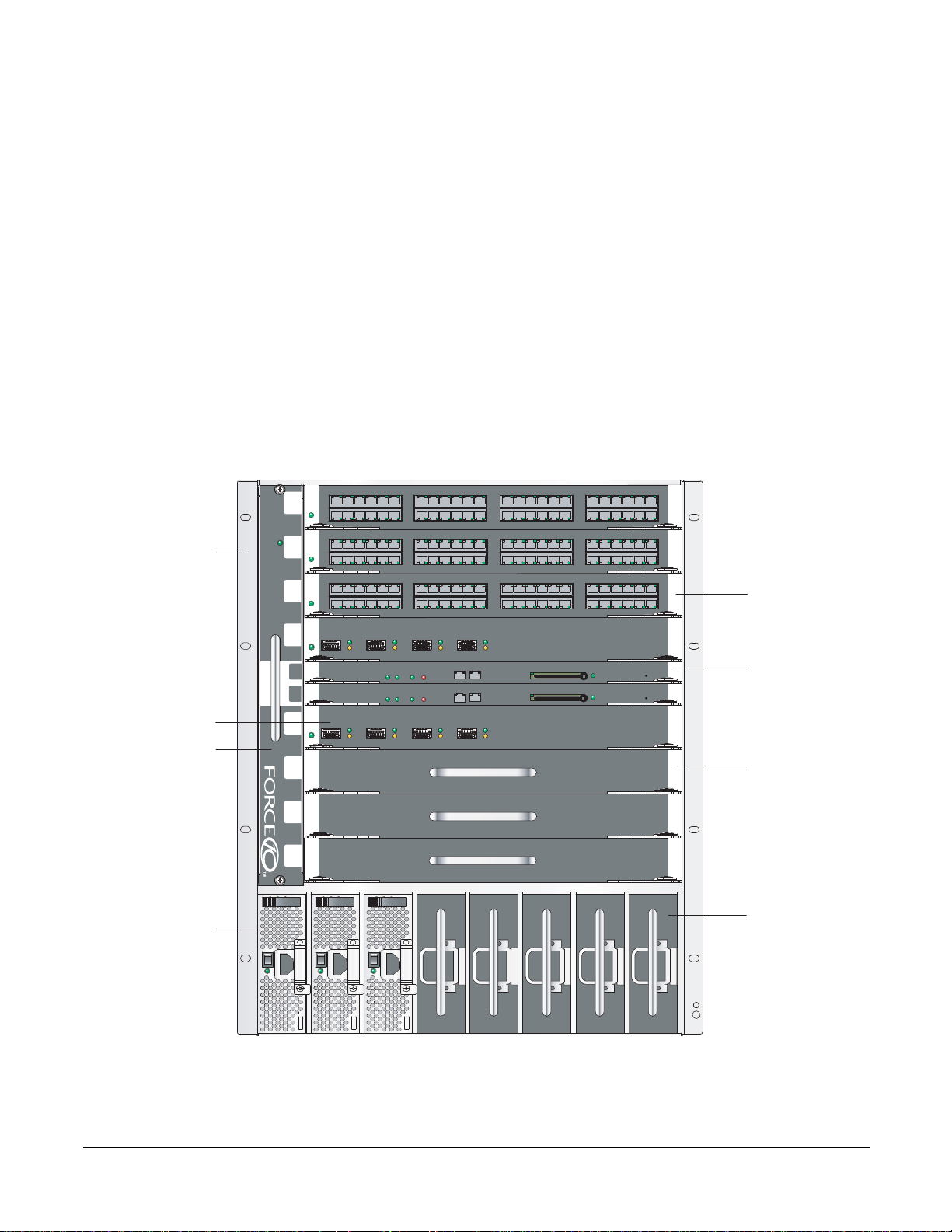
The C300 is a high performance switch/router. The 10-slot system contains two slots for Route Processor
Modules (RPMs) and eight slots for line cards.
Figure 2-1. C300 Chassis (Front View)
0
Front Mount Bracket
1
2
48-Port Line Ca
3
-Port Fiber Line Card
Fan T ray
SFM
ACTIVE
R0
R1
Status Master
Status Master
SFM
ACTIVE
4
BLNK
5
BLNK
RJ-45
Alarm
Alarm
Console
RJ-45
Console
Compact Flash
Compact Flash
Reset
Reset
Route Processo
Module
Line Card Blank
6
BLNK
7
BLNK BLNK BLNK BLNKBLNK
AC Power Supply
Unit
l
O
l
O
l
O
AC Power Supp
Unit Blank
fnC0007m
Installing and Maintaining the C300 System 11
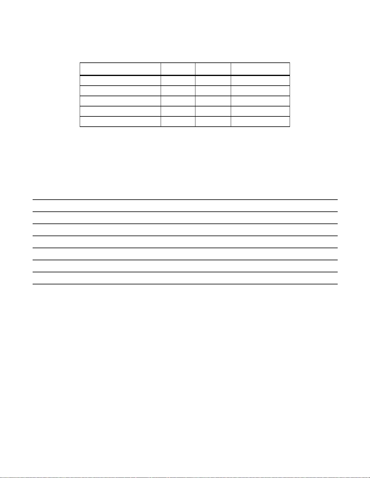
Table 2-1. C300 Component Requirements
Component Minimum Maximum Field-Replaceable
Backplane (factory installed) 1 1 No
Fan tray 1 1 Yes
RPM 1 2 Yes
Line card 1 8 Yes
AC Power Supply 1 8 Yes
C300 System Installation Process
www.dell.com | support.dell.com
The Dell Networking recommended installation process is described below.
Step Task Relevant Section in the Manual
1 Prepare the site.
2 Unpack the chassis and components.
3 Install the chassis in a rack.
4 Install the fan tray.
5 Install the RPMs and line cards.
6 Connect console and management cables.
7 Install the power supplies.
8 Switch on all of the power supplies.
Site Selection Criteria
Shipping and Storing Components
Installing the Chassis into an Equipment Rack
Installing C300 Fan Tray
Installing RPMs and Line Cards
RPM Cables
Installing AC Power Supplies
Powering Up
12 | Overview

3
Preparing the Site
Site Selection Criteria
Before beginning the installation process, make sure that the area where you intend to install your C300
meets the following safety requirements:
• It is in a restricted access area.
• It is in a dry, clean, well-ventilated, temperature-controlled room, that is away from heat sources such as
hot air vents or direct sunlight.
• It is away from sources of severe electromagnetic noise.
• Power supply is adequate for power requirements.
• Connect the C300 System to the appropriate branch circuit protection as defined by local
electrical codes.
WARNING: The C300 does not have a main disconnect device installed. It is the responsibility of the
installer to provide a suitable disconnecting device in the building installation and ensure that it is located/
installed near the equipment and is easily accessible.
• It is positioned in a rack with adequate space in the front, rear, and sides of the unit for proper
ventilation, access to cables, and maintenance access.
• Allow at least six inches (16 cm) of clearance around the side intake and exhaust vents.
• Allow at least 12 inches (30.5 cm) between two C300s or an C300 and another side airflow
chassis.
• Allow at least 18 inches in the front and 20 inches in the rear of the rack.
NOTE: The C-Series does not have an air filter, so take special care in making sure that the installation site
and the chassis itself are cleaned regularly.
Installing and Maintaining the C300 System 13
Rack Mounting
When you prepare your equipment rack:
• Make sure that the rack is bolted to the floor and braced to a wall or ceiling.
• Make sure that the rack is permanently grounded to earth ground. The equipment rack must be grounded
to the same ground point used by the service in your area.
• The AC cord is the primary ground.
When you install the chassis, use a level to ensure the chassis is installed level.
Requirements
www.dell.com | support.dell.com
There are two types of power supplies: Power Supply 1200W-AC and Power Supply 1600W-AC. The
minimum and the redundant power supplies required to operate is listed in the table below. Dell
Networking recommends the redundancy configuration.
Minimum with
Voltage Minimum PSUs
Redundant PSUs
Power Supply 1200W-AC/Power Supply
1600W-AC
Power Supply 1200W-AC 200-240 2 3
Power Supply 1600W-AC 200-240 1 2
100-120 2 3
The C300 requirements are given below:
Table 3-1. System Specifications
Parameter Specifications
Nominal Input Voltage 100 - 240 VAC 50/60 Hz
Maximum AC Power Supply Input Current
(Based on 1200 W output for 100/120 V and
1600 W 200/240 V lines)
Maximum System Power Input 9,667 KVA @ 100/120 V
Maximum Thermal Output at 100/120V 9,235 BTU/hour
Maximum Thermal Output at 200/240V 9,299 BTU/hour
14 A @ 100 V per AC Power Supply
11 A @ 120 VAC per AC Power Supply
9 A @ 200 VAC per AC Power Supply
7 A @ 240 VAC per AC Power Supply
12,596 KVA @ 200/240 V
14 | Preparing the Site

Shipping and Storing Components
CAUTION: Do not transport a C300 chassis with the components (line cards, supplies, and RPMs) installed in
the chassis. Place the components in their original protective shipping packaging and original shipping
position. Shipping components installed in the chassis or without their protective packaging, might damage
the components or the chassis backplane.
If you do not install your C300 System and components immediately , Dell Networking recommends you
properly store components (including all extra field-replaceable parts) until you are ready to install them.
Follow these indoor storage guidelines:
• Storage temperature should remain constant ranging from -40°F to 158°F (-40°C to 70°C).
• Non-condensing relative humidity should be maintained with 5 to 95%.
• Store on a dry floor, away from direct sunlight, heat, and air conditioning ducts.
• Store in a dust-free environment.
Preparing the Site | 15

www.dell.com | support.dell.com
16 | Preparing the Site
4
Installing C300 Fan Tray
The C300 chassis contains one field-replaceable fan tray. There are two types of fan tray that may be
installed: C300 variable speed fan tray contains six fans that run at varying speeds depending on system
temperature, C300 fixed speed fan tray contains six fans that run at a constant speed. For both types of
trays, air flows through the C300 system toward the fans (right to left) and is exhausted on the fan-side of
the chassis. The fan tray is accessible from the front of the chassis.
Contact Dell Networking Technical Support if you have questions concerning the fan tray for your
system.
NOTE: To ensure proper temperature and airflow control, the fan tray must always be installed and operating
properly.
NOTE: The C300 does not have an air filter so take special care in making sure that the installation site and
the chassis itself are cleaned regularly.
Figure 4-1. Inserting the Fan Tray
0
0
1
1
2
2
3
3
R0
R0
R1
R1
4
4
5
5
6
6
7
7
fnC0003mp
Installing C300 Fan Tray | 17
To install the fan tray:
Step Task
1 Slide the connector end into the fan slot (see
2 Gently push on the front of the tray until it stops. The fan tray should be flush with the chassis.
3 Use a #2 Phillips screwdriver to secure the fan tray into place by tightening the screws at the top and bottom of
the fan tray.
NOTE: The fan tray LED will remain lit when the chassis is ed up and the fan tray is functioning properly.
Figure 4-1
).
Removing the Fan Tray
A fan tray failure or a failure of a fan within a fan tray is recognized by a red fan tray LED, a lit RPM
www.dell.com | support.dell.com
alarm LED, and, if configured, an SNMP trap and alarm event. The failure requires a replacement of the
entire fan tray . While you replace the fan tray, the C300 system operates safely for approximately two (2)
minutes at an ambient temperature of 77° F (25° C).
To remove the fan tray, you must be able to pull the fan tray completely out of the slot (at least 20 inches)
NOTE: The fan tray must always be installed to ensure proper temperature and airflow control.
CAUTION: Fan blades rotate at high speeds and may cause injury if touched. Adhere to the following
instructions to avoid possible injury.
To remove the fan tray:
Step Task
1 Unscrew the retaining screws at the top and bottom of the fan tray.
2 Use the handle to pull the fan tray out approximately two inches from the back of the chassis (
until the fan blades stop rotating (up to 30 seconds), then completely remove the fan tray.
Figure 4-1
). W ait
Fan Speed
C300 variable speed fan speed is driven by temperatures measured at the sensor in the fan tray alone. The
sensor is located on the fan tray controller located in the fan tray.
Table 4-1
shows the sensor temperature
that determines the fan speed.
Table 4-1. Fan Speed and Temperature
Degrees Celsius Fan Speed
Less than 45° C (Low) 2400 RPM
Between 45 and 55° C (Med) 3200RPM
Above 55° C (High) 4000 RPM
C300 fixed speed fan speed is constant and does not change with temperature.
18 | Installing C300 Fan Tray

Installing RPMs and Line Cards
The C300 System accommodates eight line cards and two RPMs.
Route Processor Modules
The C300 system requires the installation of at least one Route Processor Module (RPM); two are
recommended.
• One RPM provides 48 Gigabits of bandwidth to each line card.
• Two RPMs provides 96 Gigabits of bandwidth to each line card.
5
RPMs are designed to be installed in either the R0 or R1 slot (see
line cards slots. RPMs are keyed differently than line cards to prevent improper installation.
NOTE: If your system contains two RPMs, both RPMs must contain the same software image.
RPM Label and LEDs
Table 5-1
Table 5-1. RPM Front Panel and LED Descriptions
Section Label Description
Management Console Port Use this RJ-45 jack for the initial system boot, as well as system configuration and
Alarm LED Red: Major Alarm—a critical condition exists (such as a severe over temperature condition).
describes the RPM LED states and the RPM front panel.
monitoring. Modem connection is not supported on the Console.
10/100/1000
Ethernet
Use this non-routable Ethernet port to download images and manage the system. FTP and
Telnet operations are supported. This port is an RJ-45.
Port LEDs:
L/A:
Blinking Amber: 100M speed
Solid Amber: 1G speed
Off: 10M speed
Speed:
Blinking Green: Link detected/ Activity
Solid Green: Link detected/ No Activity
Off: No Link/ Card Offline
See
Alarms
for more information.
Flashing red: Minor Alarm—a serious condition exists (such as a single fan failure or a line
card failure). See
Unlit: no alarm conditions.
Alarms
for more information.
Figure 2-1
). Do not force RPMs into
Installing RPMs and Line Cards | 19

Table 5-1. RPM Front Panel and LED Descriptions (continued)
Section Label Description
Flash Slot Use the compact flash card (external compact flash memory card) slot to store and retrieve
boot and system images.
In Use LED Green: flash memory card is in the process of a read or write process. Do not remove the
flash card when the In Use LED is lit.
Unlit: not in use.
Master LED Indicates that this RPM is the Primary RPM.
Green: primary
Unlit: secondary/ fatal error/ booting
Reset Button Use this recessed reset switch to reset the RPM by inserting a small object, such as a pen tip,
www.dell.com | support.dell.com
SFM Active Green: Switch Fabric is active
Status LED Green: operational
to depress the button.
Unlit: Switch Fabric is inactive
Red: card problem state
Flashing green: booting/ diagnostics
Unlit: in standby mode or is off
Line Cards
Line cards are hot-swappable. Any line card can be inserted into any line card slot. Line card slots are
labeled 0 to 7; these labels can be seen when the fan tray is installed. Do not force line cards into the RPM
slot.
Line card LEDs are described in the documentation specific to each line card. Refer to the installation
documentation that came with the card for to understand LED appearance and meaning.
Blank Panels
Blanks are required in empty slots to control airflow for adequate system cooling, personal safety, and
EMI containment during operation.
The blank panels do not have board components or connector pins. Align the blank with the guides and
gently slide toward the backplane.
NOTE: All chassis slots must be installed with operational modules or blanks. Always replace cards and blank
panels immediately.
Installing the RPMs and Line Cards
WARNING: Electrostatic discharge (ESD) damage can occur when components are mishandled. Always
wear an ESD-preventive wrist or foot-heel ground strap when handling RPMs or line cards. Place RPMs and
line cards on an antistatic surface when they are not installed.
NOTE: Unlock the levers before inserting the line card into to chassis. Fully engage the locking mechanism
once the card has been inserted; not doing so will cause damage to the card below when that card is inserted.
20 | Installing RPMs and Line Cards
NOTE: The fan tray face panel has slot number markings for the RPMs and line cards. Insert the fan tray
before the line cards to simplify RPM and line card installation.
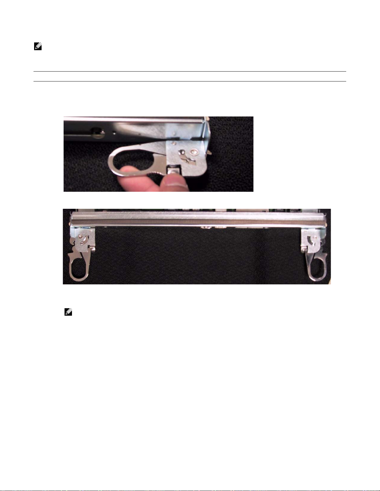
Step Task
1 Extend the left and right card levers by first pressing gently down on the thumb tabs (see
levers and then pulling the ejector levers simultaneously until they are in the open position. See
Figure 5-1
Figure 5-2
Figure 5-1. Depress the thumb tabs
Figure 5-2. Extend the levers
) in the ejector
.
2 Hold the card assembly by the metal carrier edges. Avoid touching the printed circuit board and connector pins.
3 Align the card with the guide, and gently slide it into any line card slot until the card is about halfway into the slot.
NOTE: Use the markings on the fan tray to determine which slots are for the RPMs and which are for the line
cards.
4 Continue sliding the line card until you feel the connectors engage with the chassis backplane.
Installing RPMs and Line Cards | 21
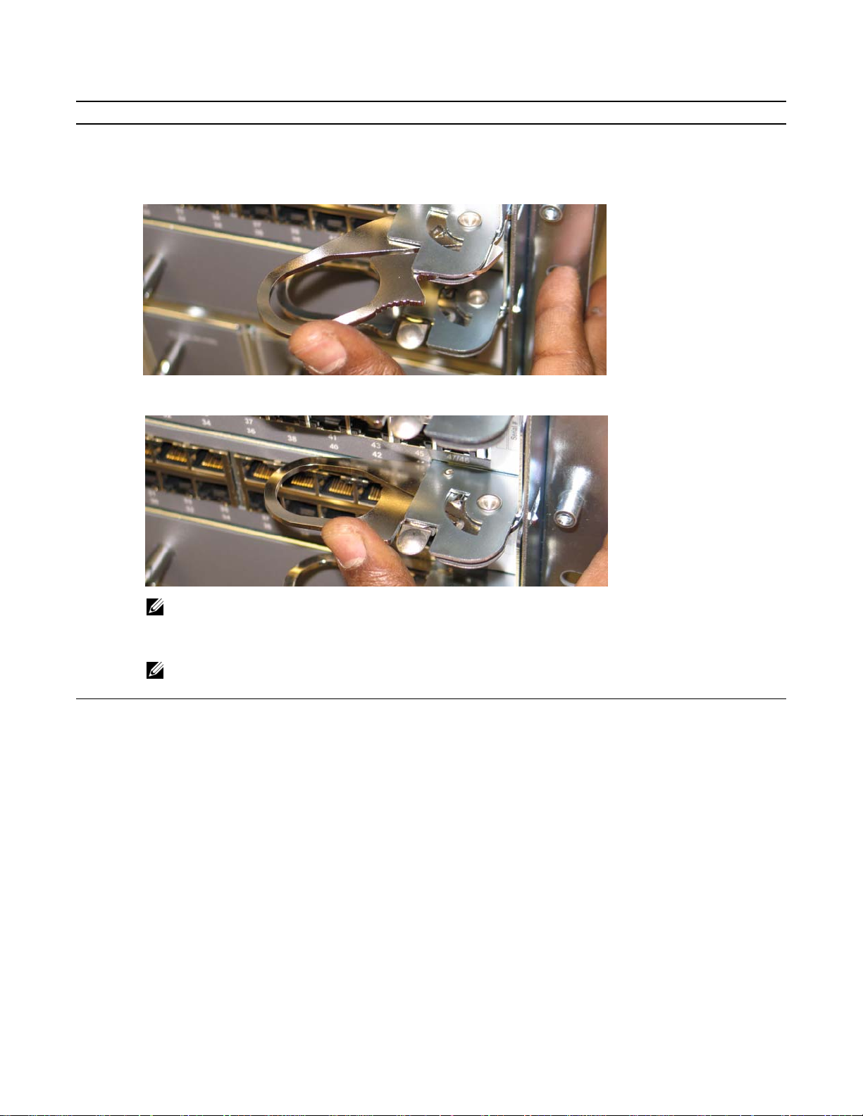
Step Task
5 Rotate the levers towards the card to seat the backplane connectors and line card in place. Push on the knurled
section of the levers until the thumb tabs pop up and lock the unit in place. See
Figure 5-3. Close the levers
www.dell.com | support.dell.com
Figure 5-4. Press the knurled section of the lever
Figure 5-3
and
Figure 5-4.
NOTE: Installing a card without fully engaging the locking mechanism will damage the EMI seal on the card
below it when that card is inserted.
6 Install a blank panel in all slots that do not have a card and secure it with the screws provided.
NOTE: The blank panels for RPMs and line cards are different sizes (RPM blanks are smaller); be sure that
blank panels are installed in the correct slots.
22 | Installing RPMs and Line Cards
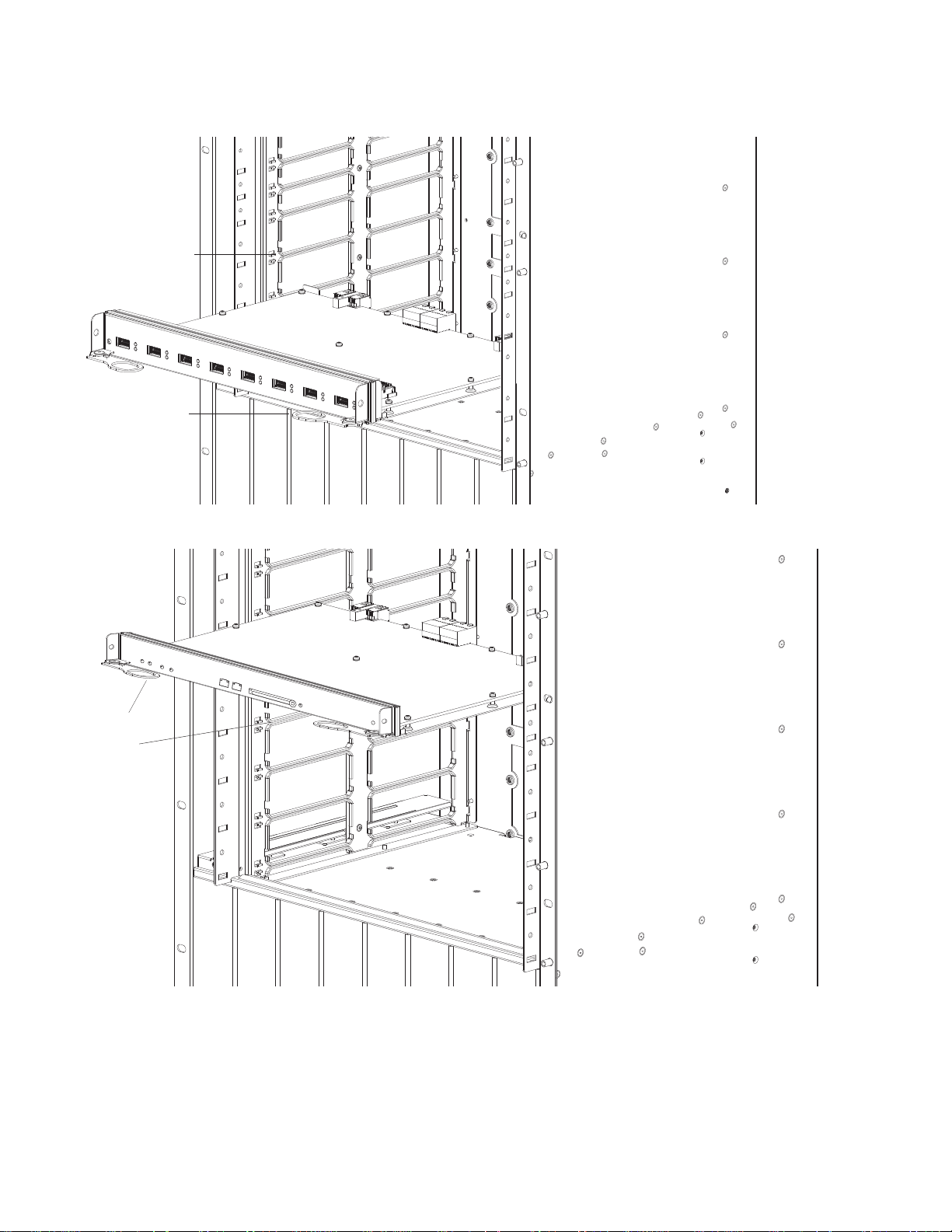
Figure 5-5. Installing a Line Card
C
Card Guide
Card Lever
Figure 5-6. Installing an RPM
fnC0005mp
Card Lever
ard Guide
fnC0006mp
Installing RPMs and Line Cards | 23
 Loading...