

Dell Alienware Aurora R8 Service Manual

Alienware Aurora R8
Service Manual
Computer Model: Alienware Aurora R8
Regulatory Model: D23M
Regulatory Type: D23M002

Notes, cautions, and warnings
NOTE: A NOTE indicates important information that helps you make better use of your product.
CAUTION: A CAUTION indicates either potential damage to hardware or loss of data and tells you how to avoid
the problem.
WARNING: A WARNING indicates a potential for property damage, personal injury, or death.
© 2018 Dell Inc. or its subsidiaries. All rights reserved. Dell, EMC, and other trademarks are trademarks of Dell Inc. or its subsidiaries.
Other trademarks may be trademarks of their respective owners.
2018 - 11
Rev. A00

Contents
Before working inside your computer................................................................................9
Before you begin ................................................................................................................................................9
After working inside your computer................................................................................10
Safety instructions.............................................................................................................11
Recommended tools.......................................................................................................... 12
Inside view of your computer............................................................................................13
System-board components............................................................................................... 14
Screw list............................................................................................................................15
Removing the stability foot...............................................................................................17
Procedure..........................................................................................................................................................17
Replacing the stability foot...............................................................................................18
Procedure..........................................................................................................................................................18
Removing the left-side cover............................................................................................19
Procedure......................................................................................................................................................... 19
Replacing the left-side cover............................................................................................20
Procedure.........................................................................................................................................................20
Removing the right-side cover.........................................................................................22
Procedure.........................................................................................................................................................22
Replacing the right-side cover.........................................................................................24
Procedure.........................................................................................................................................................24
Removing the top-cover assembly...................................................................................26
Prerequisites..................................................................................................................................................... 26
Procedure.........................................................................................................................................................26
Replacing the top-cover assembly................................................................................... 29
Procedure.........................................................................................................................................................29
Post-requisites................................................................................................................................................... 31
3

Removing the bottom cover..............................................................................................32
Prerequisites..................................................................................................................................................... 32
Procedure.........................................................................................................................................................32
Replacing the bottom cover..............................................................................................34
Procedure.........................................................................................................................................................34
Post-requisites...................................................................................................................................................34
Removing the 3.5-inch hard drive....................................................................................35
Prerequisites..................................................................................................................................................... 35
Procedure.........................................................................................................................................................35
Replacing the 3.5-inch hard drive....................................................................................37
Procedure......................................................................................................................................................... 37
Post-requisites...................................................................................................................................................38
Removing the 2.5-inch hard drive................................................................................... 39
Procedure.........................................................................................................................................................39
Prerequisites.....................................................................................................................................................40
Replacing the 2.5-inch hard drive....................................................................................41
Procedure......................................................................................................................................................... 41
Post-requisites.................................................................................................................................................. 42
Removing the hard-drive cage.........................................................................................43
Prerequisites..................................................................................................................................................... 43
Procedure.........................................................................................................................................................43
Replacing the hard-drive cage.........................................................................................44
Procedure.........................................................................................................................................................44
Post-requisites.................................................................................................................................................. 44
Removing the power-supply unit.....................................................................................45
Prerequisites.....................................................................................................................................................45
Procedure.........................................................................................................................................................45
Replacing the power-supply unit.....................................................................................49
Procedure.........................................................................................................................................................49
Post-requisites.................................................................................................................................................. 52
Removing the processor-cooling assembly......................................................................53
Prerequisites..................................................................................................................................................... 53
Procedure.........................................................................................................................................................53
4

Replacing the processor-cooling assembly......................................................................55
Procedure.........................................................................................................................................................55
Post-requisites.................................................................................................................................................. 56
Removing the coin-cell battery........................................................................................57
Prerequisites..................................................................................................................................................... 57
Procedure.........................................................................................................................................................57
Replacing the coin-cell battery........................................................................................ 58
Procedure.........................................................................................................................................................58
Post-requisites.................................................................................................................................................. 58
Removing the memory modules.......................................................................................59
Prerequisites.....................................................................................................................................................59
Procedure.........................................................................................................................................................59
Replacing the memory modules.......................................................................................60
Procedure........................................................................................................................................................ 60
Post-requisites...................................................................................................................................................61
Removing the solid-state drive........................................................................................ 62
Prerequisites..................................................................................................................................................... 62
Procedure.........................................................................................................................................................62
Replacing the solid-state drive.........................................................................................63
Procedure.........................................................................................................................................................63
Post-requisites...................................................................................................................................................63
Removing the graphics card.............................................................................................64
Prerequisites..................................................................................................................................................... 64
Procedure.........................................................................................................................................................64
Replacing the graphics card.............................................................................................66
Procedure.........................................................................................................................................................66
Post-requisites...................................................................................................................................................67
Removing the VR heat sink..............................................................................................68
Prerequisites..................................................................................................................................................... 68
Procedure.........................................................................................................................................................68
Replacing the VR heat sink.............................................................................................. 69
Procedure.........................................................................................................................................................69
Post-requisites.................................................................................................................................................. 69
5

Removing the processor fan and heat-sink assembly..................................................... 70
Prerequisites..................................................................................................................................................... 70
Procedure.........................................................................................................................................................70
Replacing the processor fan and heat-sink assembly......................................................71
Procedure..........................................................................................................................................................71
Post-requisites................................................................................................................................................... 71
Removing the processor................................................................................................... 72
Prerequisites..................................................................................................................................................... 72
Procedure.........................................................................................................................................................72
Replacing the processor....................................................................................................73
Procedure......................................................................................................................................................... 73
Post-requisites...................................................................................................................................................73
Removing the wireless card..............................................................................................74
Prerequisites......................................................................................................................................................74
Procedure......................................................................................................................................................... 74
Replacing the wireless card..............................................................................................75
Procedure.........................................................................................................................................................75
Post-requisites...................................................................................................................................................75
Removing the antennas.....................................................................................................76
Prerequisites......................................................................................................................................................76
Procedure......................................................................................................................................................... 76
Replacing the antennas.....................................................................................................78
Procedure......................................................................................................................................................... 78
Post-requisites...................................................................................................................................................79
Removing the front-chassis fan........................................................................................80
Prerequisites..................................................................................................................................................... 80
Procedure.........................................................................................................................................................80
Replacing the front-chassis fan........................................................................................82
Procedure.........................................................................................................................................................82
Post-requisites...................................................................................................................................................83
Removing the top-chassis fan...........................................................................................84
Prerequisites..................................................................................................................................................... 84
Procedure.........................................................................................................................................................84
6

Replacing the top-chassis fan...........................................................................................86
Procedure.........................................................................................................................................................86
Post-requisites...................................................................................................................................................87
Removing the optical drive...............................................................................................88
Prerequisites..................................................................................................................................................... 88
Procedure.........................................................................................................................................................88
Replacing the optical drive...............................................................................................90
Procedure........................................................................................................................................................ 90
Post-requisites...................................................................................................................................................91
Removing the front bezel ................................................................................................ 92
Prerequisites..................................................................................................................................................... 92
Procedure.........................................................................................................................................................92
Replacing the front bezel................................................................................................. 94
Procedure.........................................................................................................................................................94
Post-requisites.................................................................................................................................................. 94
Removing the power-button board................................................................................. 95
Prerequisites.....................................................................................................................................................95
Procedure.........................................................................................................................................................95
Replacing the power-button board..................................................................................96
Procedure.........................................................................................................................................................96
Post-requisites.................................................................................................................................................. 96
Removing the rear trim cover...........................................................................................97
Prerequisites..................................................................................................................................................... 97
Procedure.........................................................................................................................................................97
Replacing the rear trim cover...........................................................................................98
Procedure.........................................................................................................................................................98
Post-requisites...................................................................................................................................................98
Removing the system board.............................................................................................99
Prerequisites.....................................................................................................................................................99
Procedure.........................................................................................................................................................99
Replacing the system board............................................................................................101
Procedure........................................................................................................................................................101
Post-requisites.................................................................................................................................................102
Entering the Service Tag in the BIOS setup program......................................................................................... 102
7

System setup................................................................................................................... 103
Boot Sequence................................................................................................................................................103
Navigation keys...............................................................................................................................................103
BIOS overview................................................................................................................................................ 103
Entering BIOS setup program.......................................................................................................................... 104
System setup options.......................................................................................................................................104
Clearing CMOS Settings..................................................................................................................................107
Procedure..................................................................................................................................................107
Clearing forgotten passwords.......................................................................................................................... 108
Procedure................................................................................................................................................. 108
Flashing the BIOS............................................................................................................................................108
Troubleshooting...............................................................................................................110
Enhanced Pre-Boot System Assessment (ePSA) diagnostics................................................................................110
Running the ePSA Diagnostics.................................................................................................................... 110
System diagnostic lights....................................................................................................................................110
Flashing BIOS (USB key)...................................................................................................................................111
Flashing the BIOS............................................................................................................................................. 111
Backup media and recovery options.................................................................................................................. 111
Wi-Fi power cycle............................................................................................................................................112
Flea power release........................................................................................................................................... 112
Getting help and contacting Dell....................................................................................113
Self-help resources...........................................................................................................................................113
Contacting Dell................................................................................................................................................113
8

Before working inside your computer
NOTE: The images in this document may dier from your computer depending on the conguration you ordered.
Before you begin
1 Save and close all open les and exit all open applications.
2 Shut down your computer. Click Start → Power → Shut down.
NOTE: If you are using a dierent operating system, see the documentation of your operating system for shut-
down instructions.
3 Disconnect your computer and all attached devices from their electrical outlets.
4 Disconnect all attached network devices and peripherals, such as keyboard, mouse, and monitor from your computer.
5 Remove any media card and optical disc from your computer, if applicable.
6 After the computer is unplugged, press and hold the power button for 5 seconds to ground the system board.
9

After working inside your computer
CAUTION: Leaving stray or loose screws inside your computer may severely damage your computer.
1 Replace all screws and ensure that no stray screws remain inside your computer.
2 Connect any external devices, peripherals, or cables you removed before working on your computer.
3 Replace any media cards, discs, or any other parts that you removed before working on your computer.
4 Connect your computer and all attached devices to their electrical outlets.
5 Turn on your computer.
10
Safety instructions
Use the following safety guidelines to protect your computer from potential damage and ensure your personal safety.
WARNING: Before working inside your computer, read the safety information that shipped with your computer. For
more safety best practices, see the Regulatory Compliance home page at www.dell.com/regulatory_compliance.
WARNING: Disconnect all power sources before opening the computer cover or panels. After you nish working
inside the computer, replace all covers, panels, and screws before connecting to the electrical outlet.
CAUTION: To avoid damaging the computer, ensure that the work surface is at and clean.
CAUTION: To avoid damaging the components and cards, handle them by their edges, and avoid touching pins and
contacts.
CAUTION: You should only perform troubleshooting and repairs as authorized or directed by the Dell technical
assistance team. Damage due to servicing that is not authorized by Dell is not covered by your warranty. See the
safety instructions that shipped with the product or at www.dell.com/regulatory_compliance.
CAUTION: Before touching anything inside your computer, ground yourself by touching an unpainted metal surface,
such as the metal at the back of the computer. While you work, periodically touch an unpainted metal surface to
dissipate static electricity, which could harm internal components.
CAUTION: When you disconnect a cable, pull on its connector or on its pull tab, not on the cable itself. Some cables
have connectors with locking tabs or thumb-screws that you must disengage before disconnecting the cable. When
disconnecting cables, keep them evenly aligned to avoid bending any connector pins. When connecting cables,
ensure that the ports and connectors are correctly oriented and aligned.
CAUTION: Press and eject any installed card from the media-card reader.
11

Recommended tools
The procedures in this document may require the following tools:
• Philips screwdriver #1
• Flat-head screwdriver
• Plastic scribe
12
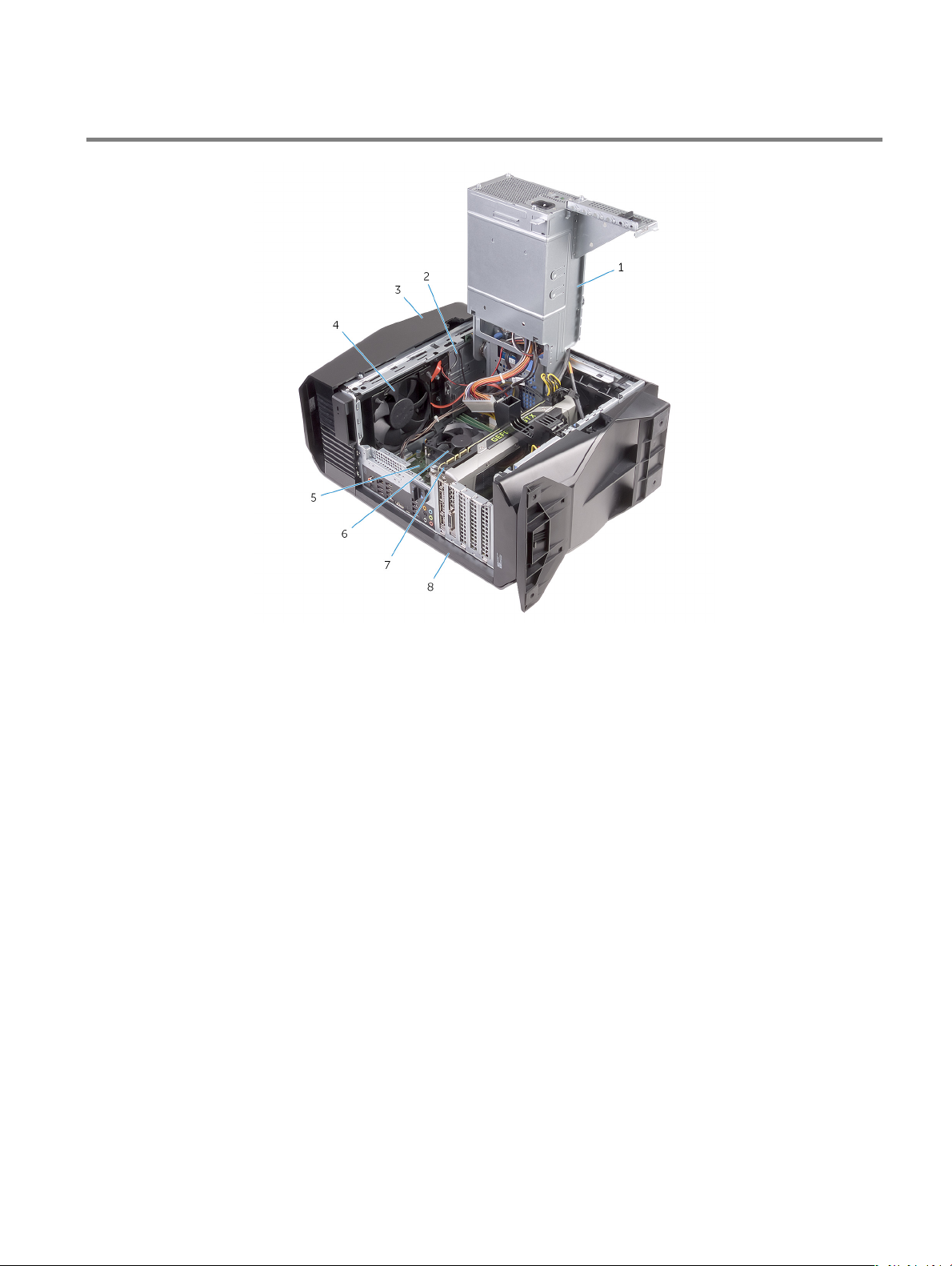
Inside view of your computer
1 power-supply unit 2 optical-drive assembly
3 top cover 4 top-chassis fan
5 system board 6 processor fan and heat-sink assembly
7 graphics card 8 right-side cover
13

System-board components
1 top-chassis fan (TOP_FAN) 2 processor-cooling assembly pump-fan connector
(PUMP_FAN)
3 processor-fan connector (CPU_FAN) 4 memory-module slot 1 (XMM1)
5 memory-module slot 2 (XMM2) 6 memory-module slot 3 (XMM3)
7 memory-module slot 4 (XMM4) 8 front-chassis fan connector (FRONT_FAN)
9 SATA 6 Gbps drive connector (SATA1) 10 SATA 6 Gbps drive connector (SATA2)
11 SATA 6 Gbps drive connector (SATA3) 12 SATA 6 Gbps drive connector (SATA4)
13 solid-state drive slot (M.2 SSD) 14 CMOS reset jumper (CMOS JUMPER)
15 Password reset jumper (PASSWORD JUMPER) 16 PCI-Express x16 mechanical/x8 electrical slot (SLOT4)
17 LED controller connector (LED_CONTROLLER) 18 PCI-Express x4 slot (SLOT3)
19 PCI-Express x4 slot (SLOT2) 20 PCI-Express x16 mechanical/x8 electrical slot (SLOT1)
21 graphics-card power connector (GPU_POWER) 22 wireless-card slot (M.2 WIFI)
23 processor socket (CPU1)
14
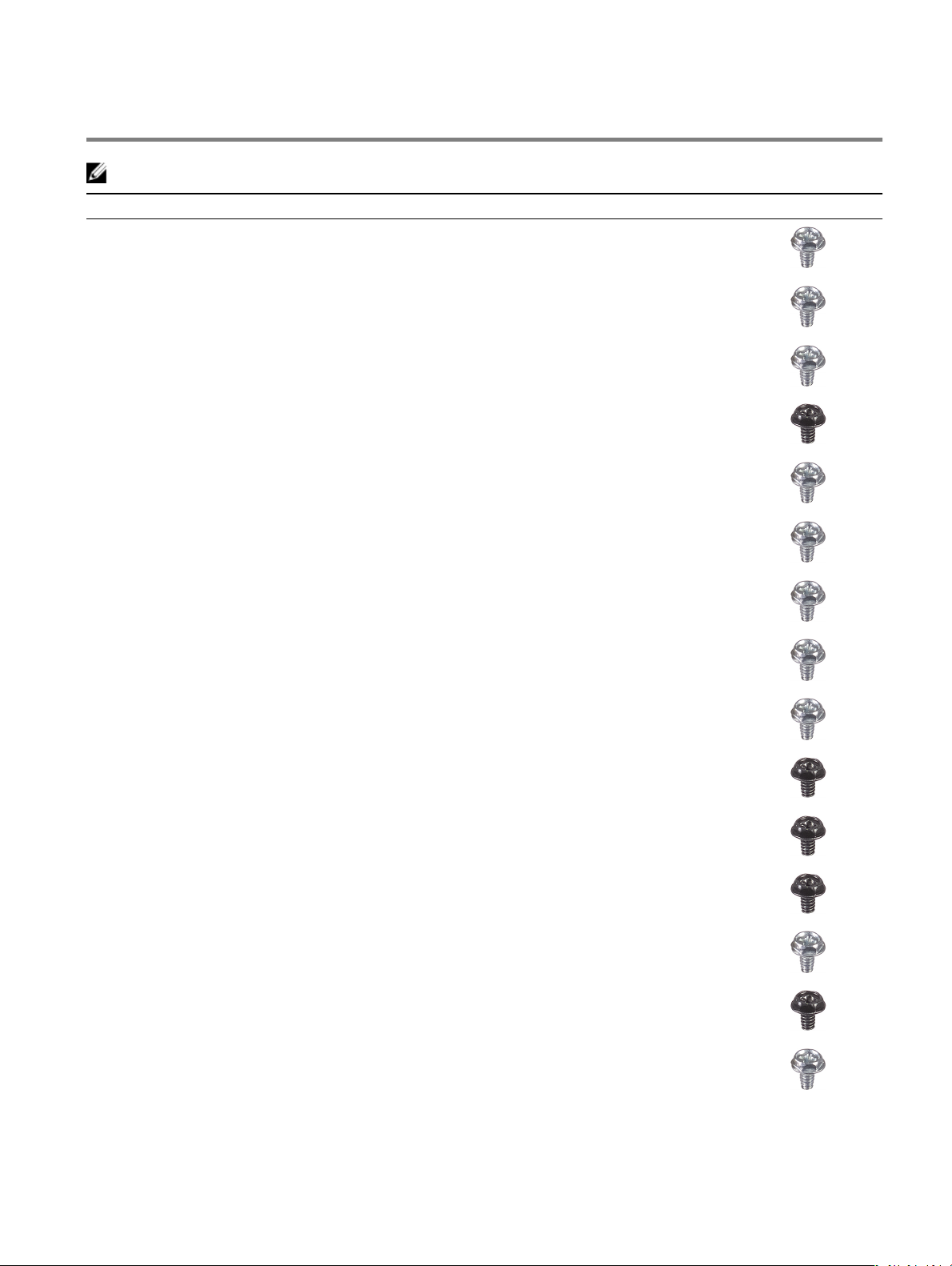
Screw list
NOTE: Screw color may vary with the conguration ordered.
Component Secured to Screw type Quantity Screw image
3.5-inch hard-drive cage Chassis #6-32 X 1/4'' 2
2.5-inch hard-drive cage Chassis #6-32 X 1/4'' 4
Power-supply unit hinge Chassis #6-32 X 1/4'' 6
#6-32 X 1/4'' BLK 3
Power-supply unit Power-supply unit
hinge
Power-supply unit bracket #6-32 X 1/4'' 2
Optical-drive assembly Chassis #6-32 X 1/4'' 2
System board Chassis #6-32 X 1/4'' 8
Top cover Chassis #6-32 X 1/4'' 2
Top I/O assembly Chassis #6-32 X 1/4'' BLK 4
Processor-cooling assembly bracket Chassis #6-32 X 1/4'' BLK 2
Processor-cooling assembly radiator Processor-cooling
assembly bracket
#6-32 X 1/4'' 4
#6-32 X 1/4'' BLK 4
Top-chassis fan assembly Chassis #6-32 X 1/4'' 1
Top-chassis fan bracket Chassis #6-32 X 1/4'' BLK 1
Antenna assembly Chassis #6-32 X 1/4'' 2
15
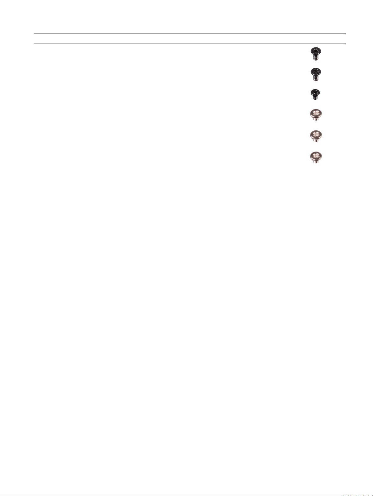
Component Secured to Screw type Quantity Screw image
Power-button board Top cover M3 X 4 2
Rubber foot Bottom cover M3 X 4 4
M.2 SSD card System board Stando M2 1
M2 X 2.5 1
Optical-drive bracket Optical drive M2 X 2.5 1
WLAN bracket System board M2 X 2.5 1
16
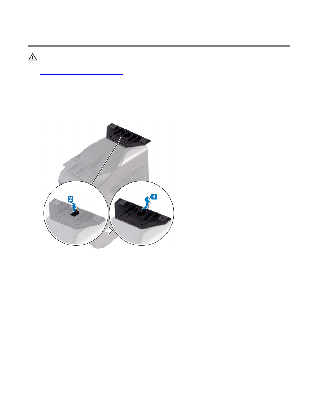
Removing the stability foot
WARNING: Before working inside your computer, read the safety information that shipped with your computer and
follow the steps in Before working inside your computer. After working inside your computer, follow the instructions
in
After working inside your computer. For more safety best practices, see the Regulatory Compliance home page at
www.dell.com/regulatory_compliance.
Procedure
1 Place the computer on a clean and at surface with the bottom cover facing up.
2 Pull the securing tab to release the stability foot from the slots on the bottom cover.
3 Lift the stability foot o the bottom cover.
4 Lay the computer on its side.
17
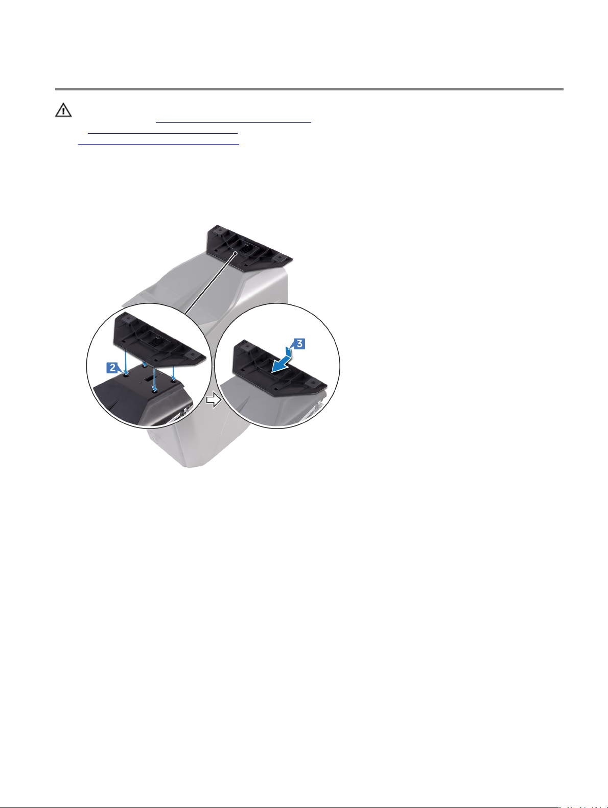
Replacing the stability foot
WARNING: Before working inside your computer, read the safety information that shipped with your computer and
follow the steps in Before working inside your computer. After working inside your computer, follow the instructions
in
After working inside your computer. For more safety best practices, see the Regulatory Compliance home page at
www.dell.com/regulatory_compliance.
Procedure
1 Place the computer on a clean and at surface with the bottom cover facing up.
2 Align the tabs on the stability foot with the slots on the bottom cover and snap the stability foot to lock it in place.
3 Turn the computer over and place it in upright position.
18
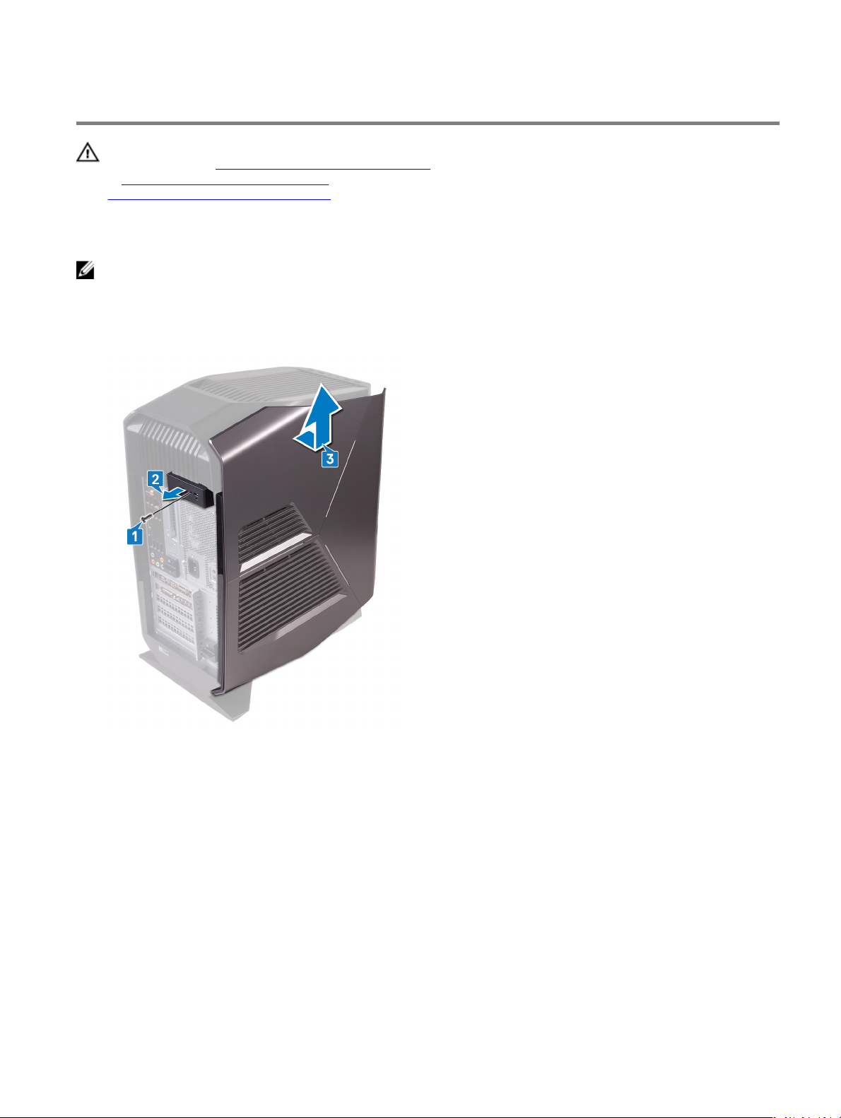
Removing the left-side cover
WARNING: Before working inside your computer, read the safety information that shipped with your computer and
follow the steps in Before working inside your computer. After working inside your computer, follow the instructions
in
After working inside your computer. For more safety best practices, see the Regulatory Compliance home page at
www.dell.com/regulatory_compliance.
Procedure
NOTE: Ensure that you remove the security cable and security screw from the security-cable slot (if applicable).
1 Remove the screw (#6-32 X 1/4" BLK) that secures the side-panel release latch to the chassis.
2 Pull the side-panel release latch.
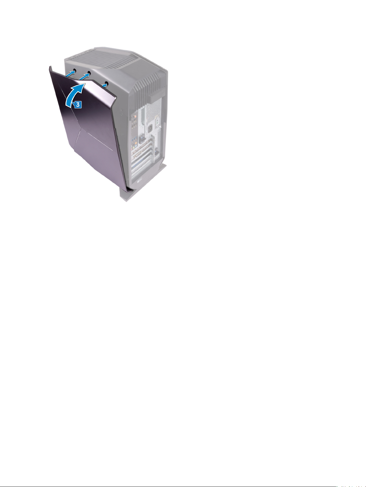
3 Release the left-side cover away from the chassis and then lift it from the computer.
19
Replacing the left-side cover
WARNING: Before working inside your computer, read the safety information that shipped with your computer and
follow the steps in Before working inside your computer. After working inside your computer, follow the instructions
in
After working inside your computer. For more safety best practices, see the Regulatory Compliance home page at
www.dell.com/regulatory_compliance.
Procedure
1 Align the tabs on the left-side cover with the slots on the chassis.
2 Rotate the left-side cover towards the chassis until it snaps into place.
20
3 Replace the screw (#6-32 X 1/4" BLK) that secures the side-panel release latch to the chassis.
21
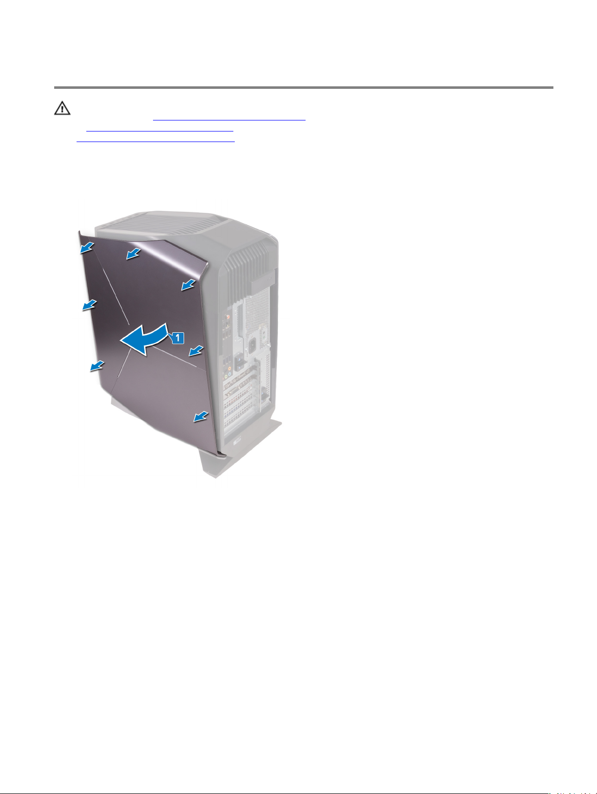
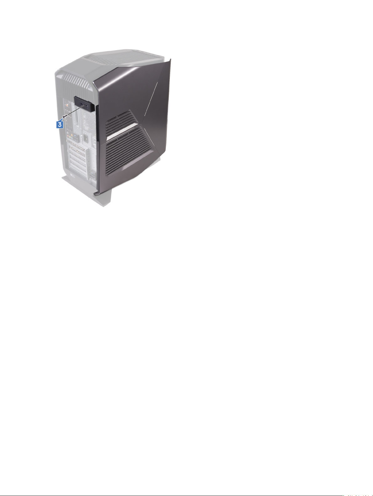
Removing the right-side cover
WARNING: Before working inside your computer, read the safety information that shipped with your computer and
follow the steps in Before working inside your computer. After working inside your computer, follow the instructions
in
After working inside your computer. For more safety best practices, see the Regulatory Compliance home page at
www.dell.com/regulatory_compliance.
Procedure
1 Carefully pry around the edges of the right-side cover from the chassis.
2 Disconnect the lighting cable from the right-side cover.
22
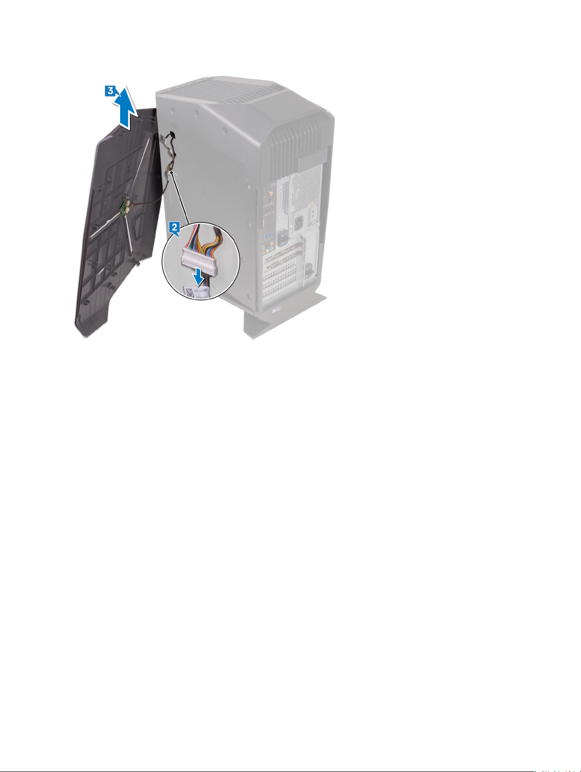
3 Lift the right-side cover o the chassis.
23
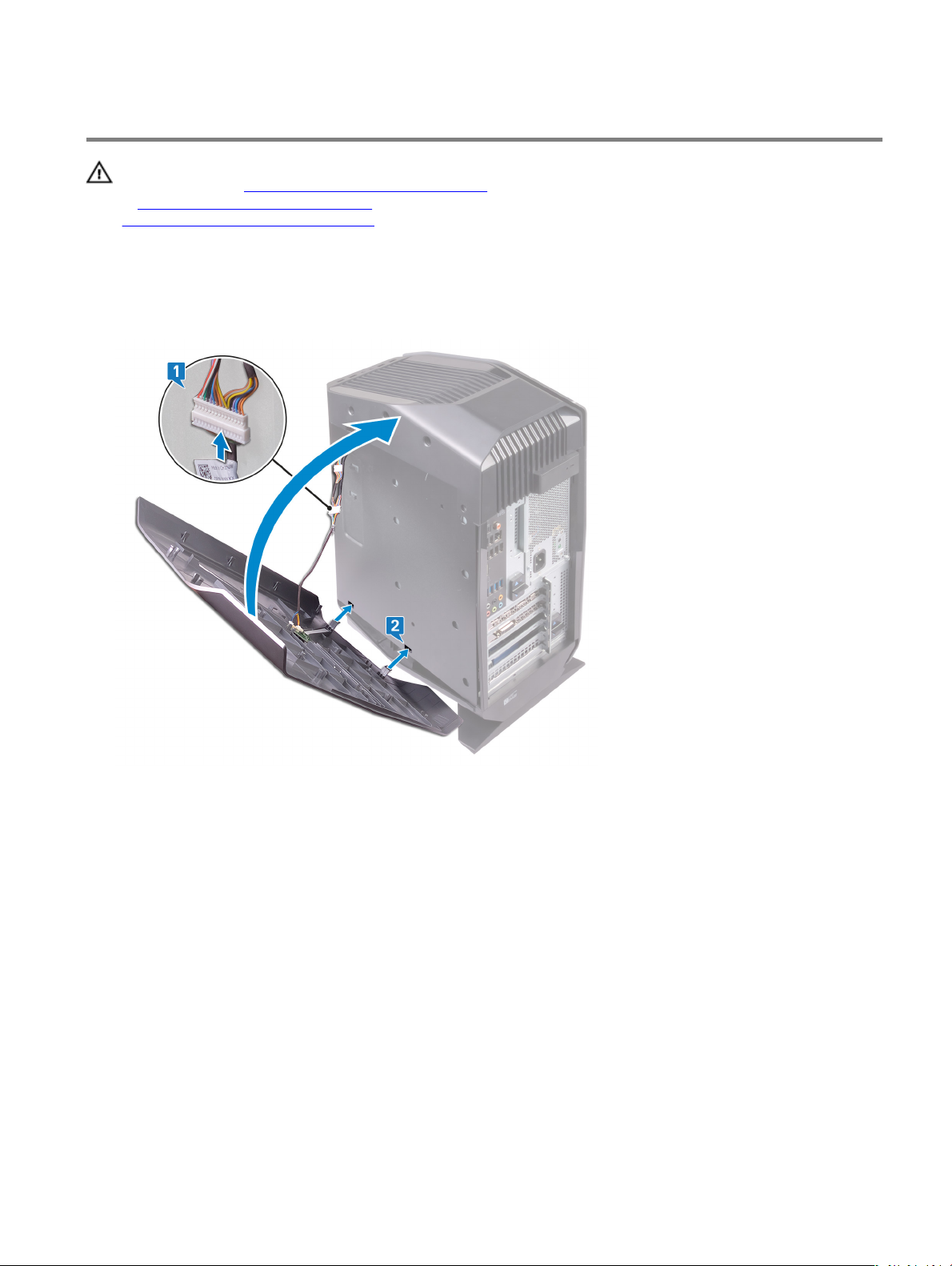
Replacing the right-side cover
WARNING: Before working inside your computer, read the safety information that shipped with your computer and
follow the steps in Before working inside your computer. After working inside your computer, follow the instructions
in
After working inside your computer. For more safety best practices, see the Regulatory Compliance home page at
www.dell.com/regulatory_compliance.
Procedure
1 Connect the lighting cable to the right-side cover.
2 Align the tabs on the right-side cover with the slots on the chassis
24
3 Rotate the right-side cover towards the chassis until it snaps into place.
25
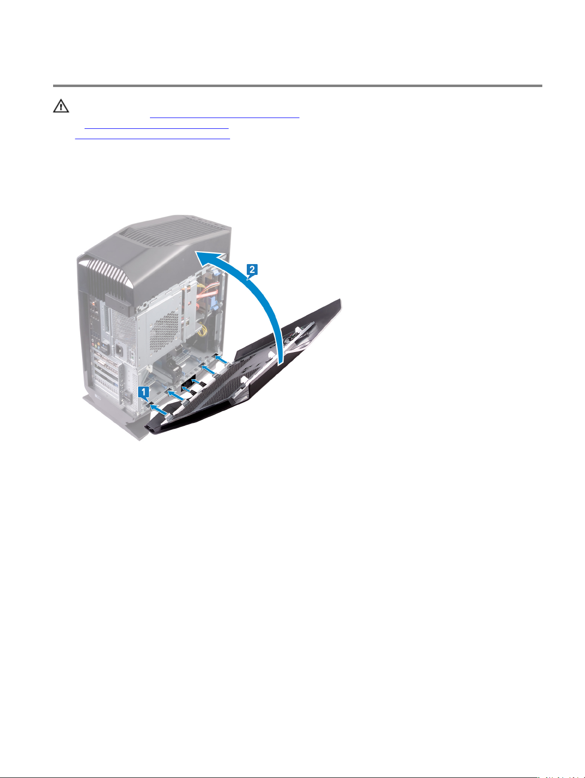
Removing the top-cover assembly
WARNING: Before working inside your computer, read the safety information that shipped with your computer and
follow the steps in Before working inside your computer. After working inside your computer, follow the instructions
in
After working inside your computer. For more safety best practices, see the Regulatory Compliance home page at
www.dell.com/regulatory_compliance.
Prerequisites
1 Remove the left-side cover.
2 Remove the right-side cover.
Procedure
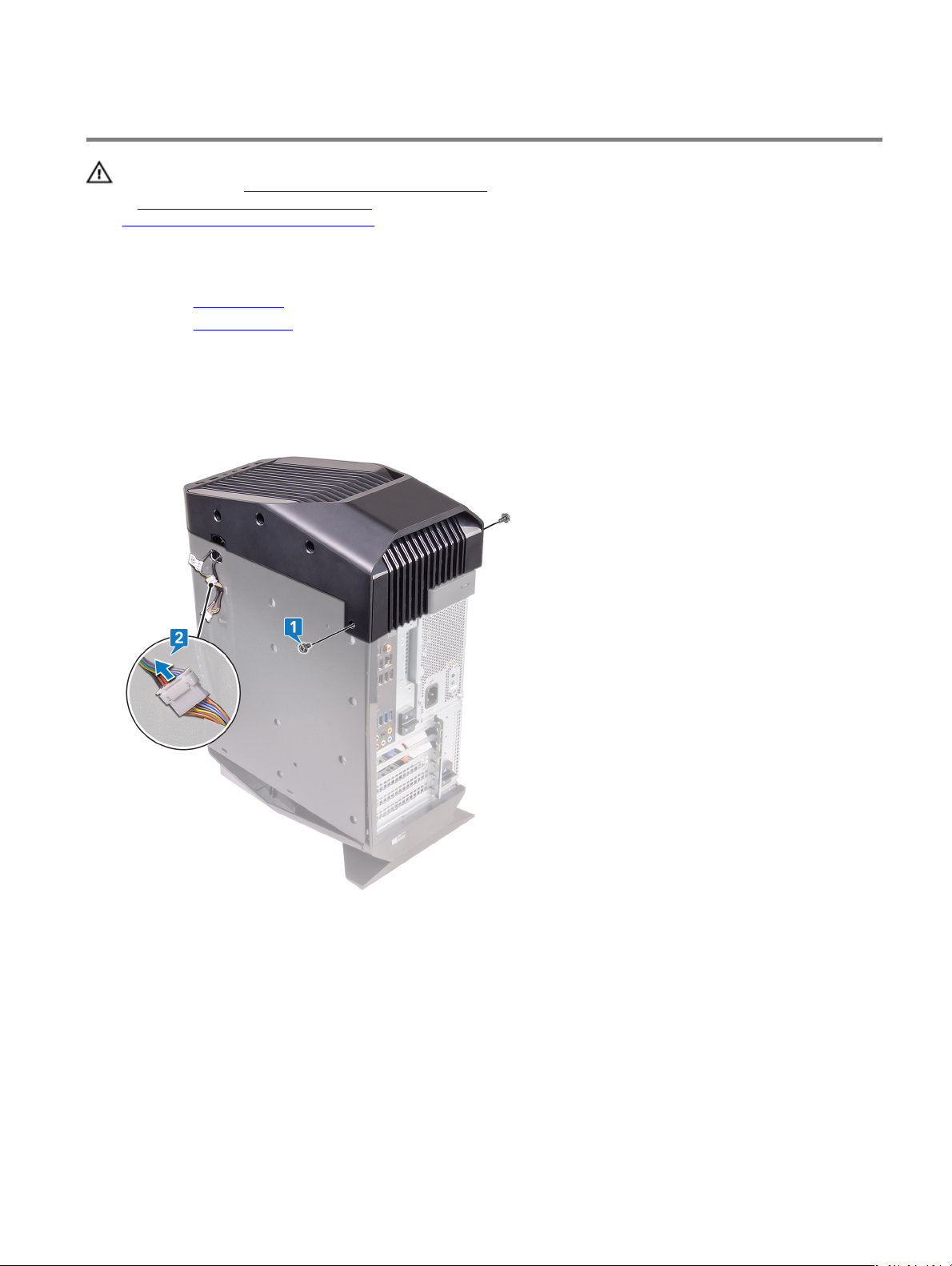
1 Remove the two screws (#6-32 X 1/4") that secure the top cover to the chassis.
2 Disconnect the lighting cable from the top cover.
3 Slide the lighting cable through the slot on the chassis.
4 Starting from the rear, release the tabs on the top cover from the slots on the chassis.
26
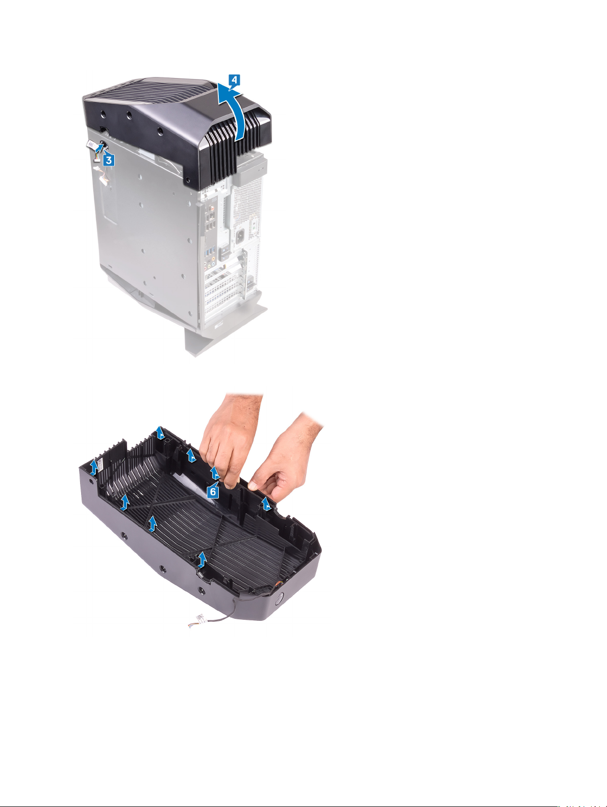
5 Lift the top cover o the chassis from the rear.
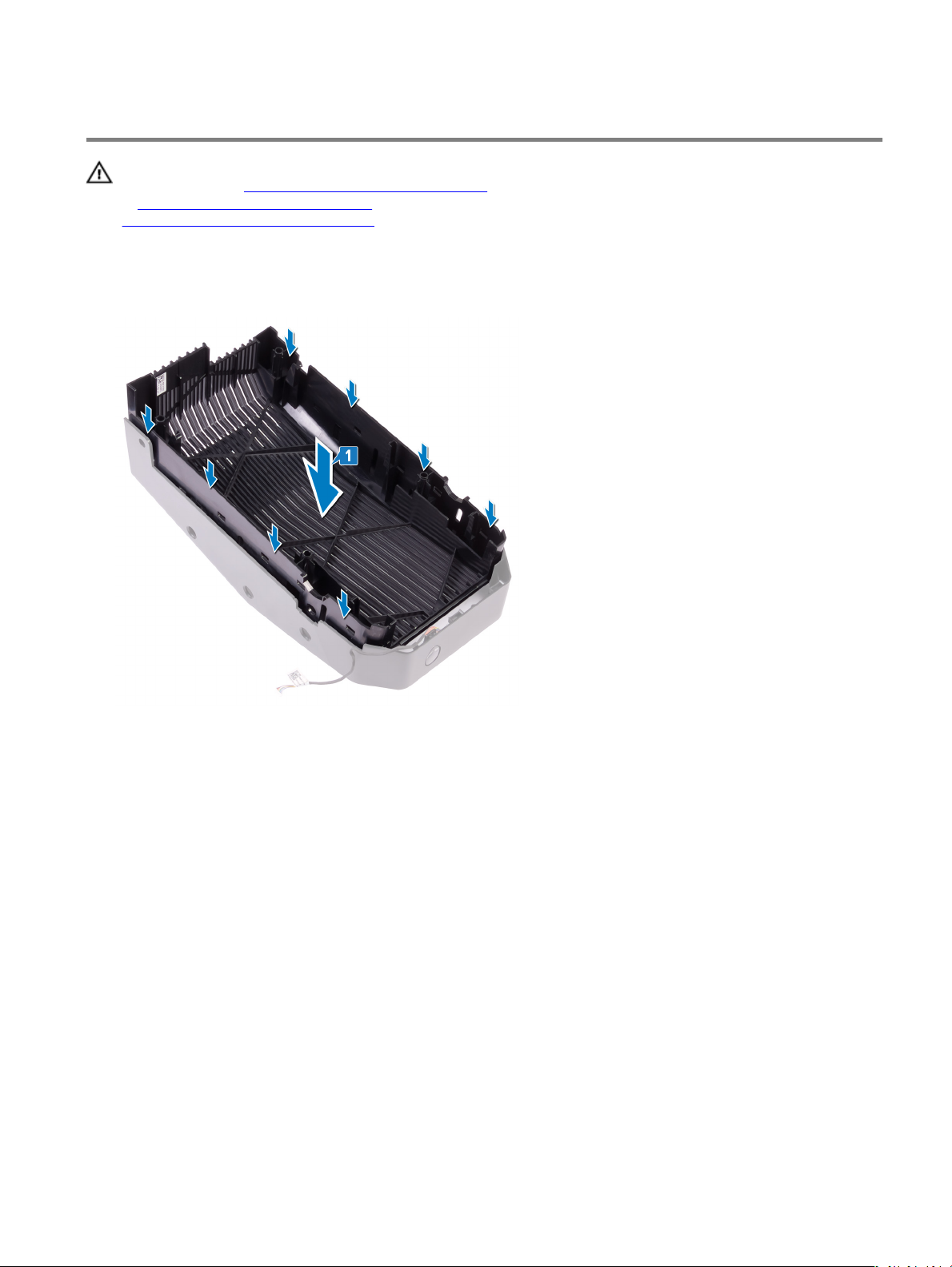
6 Turn the top cover over, release the tabs on the top cover from the slots on the top bezel.
27
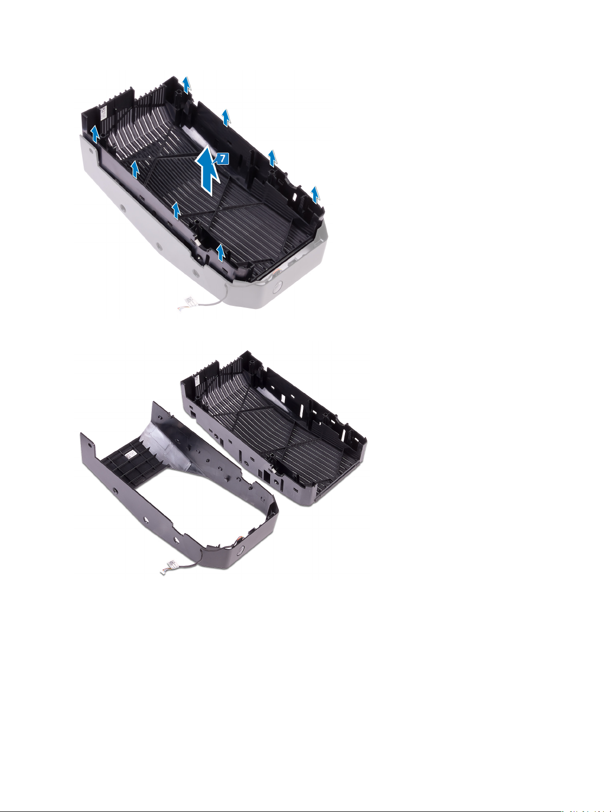
7 Lift the top cover from the top bezel.
8 You are left with top bezel and top cover.
28
Replacing the top-cover assembly
WARNING: Before working inside your computer, read the safety information that shipped with your computer and
follow the steps in Before working inside your computer. After working inside your computer, follow the instructions
in
After working inside your computer. For more safety best practices, see the Regulatory Compliance home page at
www.dell.com/regulatory_compliance.
Procedure
1 Align the tabs on the top cover with the slots on the top bezel and snap the top cover into place.
2 Slide the lighting cable through the slot on the chassis.
29
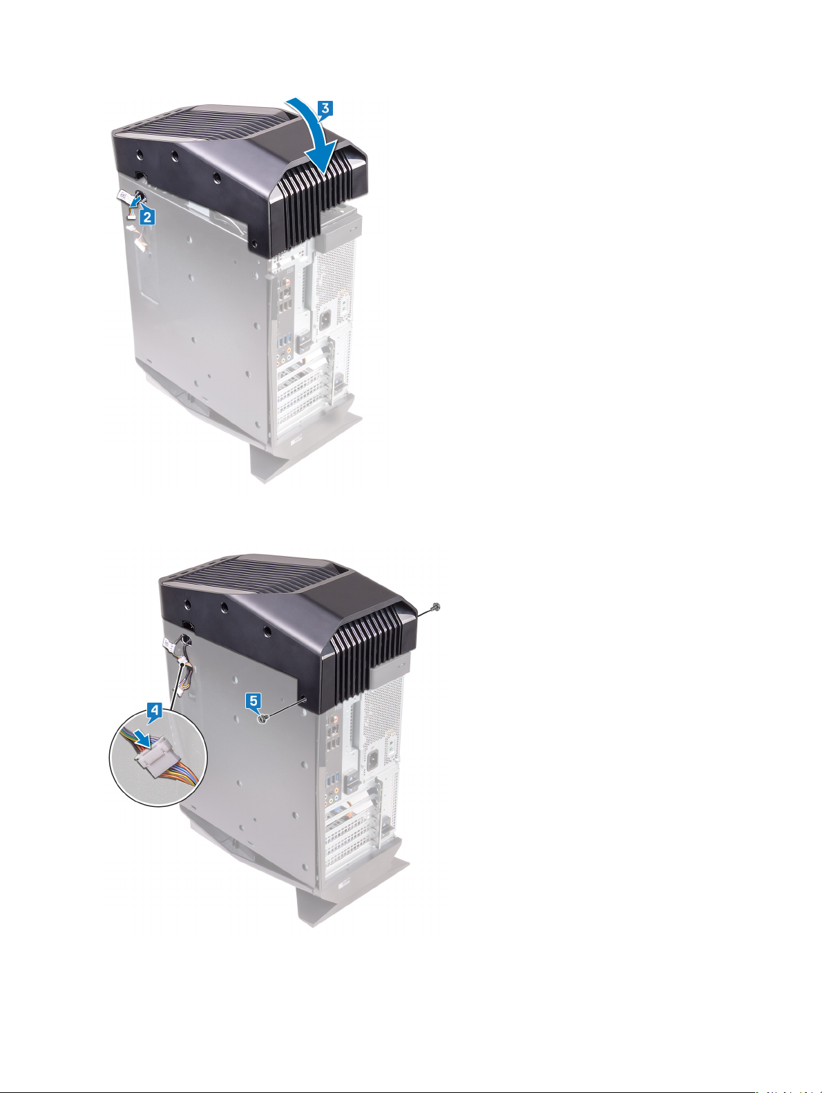
3 Align the tabs on the top cover with the slots on the chassis and snap the top cover into place.
4 Connect the lighting cable to the top cover.
5 Replace the two screws (#6-32 X 1/4") that secure the top cover to the chassis.
30
 Loading...