

Page 1
TR1616
Performance I/O
Owner’s Manual
Page 2
IMPORTANT SAFETY INSTRUCTIONS
WARNING FOR YOUR PROTECTION
READ THE FOLLOWING:
KEEP THESE INSTRUCTIONS
HEED ALL WARNINGS
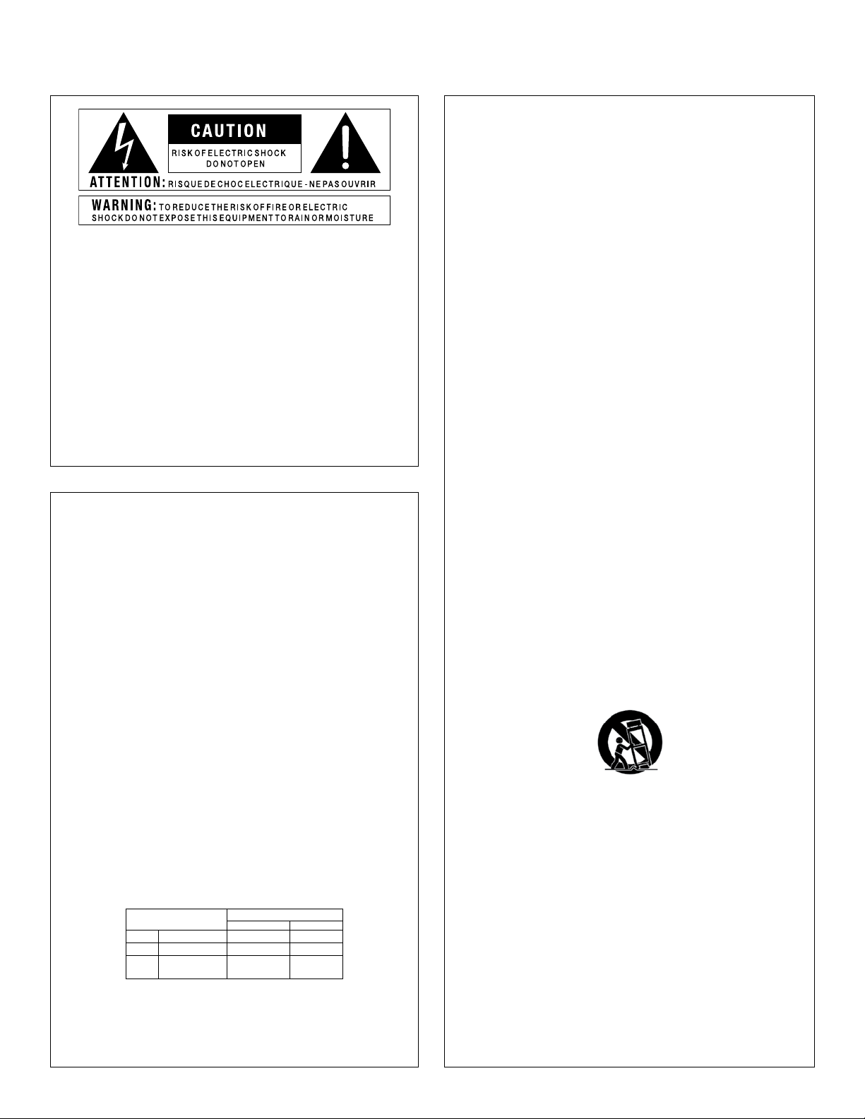
The symbols shown above are internationally accepted symbols that warn of
potential hazards with electrical products. The lightning flash with arrowpoint in
an equilateral triangle means that there are dangerous voltages present within
the unit. The exclamation point in an equilateral triangle indicates that it is
necessary for the user to refer to the owner’s manual.
These symbols warn that there are no user serviceable parts inside the unit.
Do not open the unit. Do not attempt to service the unit yourself. Refer all
servicing to qualified personnel. Opening the chassis for any reason will void
the manufacturer’s warranty. Do not get the unit wet. If liquid is spilled on the
unit, shut it off immediately and take it to a dealer for service. Disconnect the
unit during storms to prevent damage.
SAFETY INSTRUCTIONS
NOTICE FOR CUSTOMERS IF YOUR UNIT IS EQUIPPED WITH A POWER CORD.
WARNING: THIS APPLIANCE SHALL BE CONNECTED TO A MAINS SOCKET OUTLET WITH A PROTECTIVE
EARTHING CONNECTION.
THE CORES IN THE MAINS LEAD ARE COLOURED IN ACCORDANCE WITH THE FOLLOWING CODE:
GREEN AND YELLOW - EARTH BLUE - NEUTRAL BROWN - LIVE
AS COLOURS OF THE CORES IN THE MAINS LEAD OF THIS APPLIANCE MAY NOT CORRESPOND WITH
THE COLOURED MARKINGS IDENTIFYING THE TERMINALS IN YOUR PLUG, PROCEED AS FOLLOWS:
FOLLOW ALL INSTRUCTIONS
the apparatus shall not be exposed to dripping or splashing liquid and no object filled
with liquid, such as vases, shall be placed on the apparatus.
CLEAN ONLY WITH A DRY CLOTH.
DO NOT BLOCK ANY OF THE VENTILATION OPENINGS. INSTALL IN ACCORDANCE WITH
THE MANUFACTURER’S INSTRUCTIONS.
DO NOT INSTALL NEAR ANY HEAT SOURCES SUCH AS RADIATORS, HEAT REGISTERS,
STOVES, OR OTHER APPARATUS (INCLUDING AMPLIFIERS) THAT PRODUCE HEAT.
ONLY USE ATTACHMENTS/ACCESSORIES SPECIFIED BY THE MANUFACTURER.
UNPLUG THIS APPARATUS DURING LIGHTNING STORMS OR WHEN UNUSED FOR LONG
PERIODS OF TIME.
Do not defeat the safety purpose of the polarized or grounding-type plug. A polarized
plug has two blades with one wider than the other. A grounding type plug has two
blades and a third grounding prong. The wide blade or third prong are provided for your
safety. If the provided plug does not fit your outlet, consult an electrician for replacement of the obsolete outlet.
Protect the power cord from being walked on or pinched particularly at plugs, convenience receptacles, and the point where they exit from the apparatus.
Use only with the cart stand, tripod bracket, or table specified by the manufacture,
or sold with the apparatus. When a cart is used, use caution when moving the cart/
apparatus combination to avoid injury from tip-over.
• THE CORE WHICH IS COLOURED GREEN AND YELLOW MUST BE CONNECTED TO THE TERMINAL
IN THE PLUG MARKED WITH THE LETTER E, OR WITH THE EARTH SYMBOL, OR COLOURED GREEN,
OR GREEN AND YELLOW.
• THE CORE WHICH IS COLOURED BLUE MUST BE CONNECTED TO THE TERMINAL MARKED N OR
COLOURED BLACK.
• THE CORE WHICH IS COLOURED BROWN MUST BE CONNECTED TO THE TERMINAL MARKED L OR
COLOURED RED.
THIS EQUIPMENT MAY REQUIRE THE USE OF A DIFFERENT LINE CORD, ATTACHMENT PLUG, OR BOTH,
DEPENDING ON THE AVAILABLE POWER SOURCE AT INSTALLATION. IF THE ATTACHMENT PLUG NEEDS
TO BE CHANGED, REFER SERVICING TO QUALIFIED SERVICE PERSONNEL WHO SHOULD REFER TO THE
TABLE BELOW. THE GREEN/YELLOW WIRE SHALL BE CONNECTED DIRECTLY TO THE UNITS CHASSIS.
CONDUCTOR
L LIVE BROWN BLACK
N NEUTRAL BLUE WHITE
E EARTH GND GREEN/YEL GREEN
WARNING: IF THE GROUND IS DEFEATED, CERTAIN FAULT CONDITIONS IN THE UNIT OR IN THE
SYSTEM TO WHICH IT IS CONNECTED CAN RESULT IN FULL LINE VOLTAGE BETWEEN CHASSIS AND
EARTH GROUND. SEVERE INJURY OR DEATH CAN THEN RESULT IF THE CHASSIS AND EARTH GROUND
ARE TOUCHED SIMULTANEOUSLY.
WIRE COLOR
Normal Alt
Refer all servicing to to qualified service personnel. Servicing is required when the apparatus has been damaged in any way, such as power-supply cord or plug is damaged,
liquid has been spilled or objects have fallen into the apparatus, the apparatus has been
exposed to rain or moisture, does not operate normally, or has been dropped.
POWER ON/OFF SWITCH: The Power switch used in this piece of equipment DOES NOT
break the connection from the mains.
MAINS DISCONNECT: The plug shall remain readily operable. For rack-mount or installation where plug is not accessible, an all-pole mains switch with a contact separation
of at least 3 mm in each pole shall be incorporated into the electrical installation of the
rack or building.
If connected to 240V supply, a suitable CSA/UL certified power cord shall be used for
this supply.
This Equipment is intended for rack mount use only.
Page 3
IMPORTANT SAFETY INSTRUCTIONS
ELECTROMAGNETIC COMPATIBILITY
This device complies with part 15 of the FCC Rules and the Product Specifications noted on the Declaration of Conformity.
Operation is subject to the following two conditions:
• this device may not cause harmful interference, and
• this device must accept any interference received, including
interference that may cause undesired operation.
Operation of this unit within significant electromagnetic fields
should be avoided.
• use only shielded interconnecting cables.
U.K. MAINS PLUG WARNING
A molded mains plug that has been cut off from the cord is
unsafe. Discard the mains plug at a suitable disposal facility.
NEVER UNDER ANY CIRCUMSTANCES SHOULD
YOU INSERT A DAMAGED OR CUT MAINS PLUG
INTO A 13 AMP POWER SOCKET.
Do not use the mains plug without the fuse cover in place.
Replacement fuse covers can be obtained from your local retailer.
Replacement fuses are 13 amps and MUST be ASTA approved to
BS1362.
If you want to dispose this product, do n ot mix it with general household waste. There is a
separate collection system for used electronic products in accordance with legislation that
requires proper treatment, recovery and recycling.
Private household in the 25 member states of the EU, in Switzerland and Norway may return their used
electronic products free of charge to designated collection facilities or to a retailer (if you purchase a similar
new one).
For Countries not mentioned above, please contact your local authorities for a correct method of disposal.
By doing so you will ensure that your disposed product undergoes the necessary treatment, recovery and
recycling and thus prevent potential negative effects on the environment and human health.
DECLARATION OF CONFORMITY
Manufacturer’s Name: dbx Professional Products
Manufacturer’s Address: 8760 S. Sandy Parkway
Sandy, Utah 84070, USA
declares that the product:
Product name: TR1616
Note: Product name may be suffixed by the EU.
Product option: None
conforms to the following Product Specifications:
Safety: IEC 60065 -01+Amd 1
EMC: EN 55022:2006
EN 55024:1998
FCC Part 15
Supplementary Information:
The product herewith complies with the requirements of the:
Low Voltage Directive 2006/95/EC
EMC Directive 2004/108/EC.
RoHS Directive 2002/95/EC
WEEE Directive 2002/96/EC
With regard to Directive 2005/32/EC and EC Regulation 1275/2008
of 17 December 2008, this product is designed, produced, and
classified as Professional Audio Equipment and thus is exempt from this
Directive.
Roger Johnsen
Director, Engineering
Signal Processing
8760 S. Sandy Parkway
Sandy, Utah 84070, USA
Date: November 14, 2012
European Contact: Your local dbx Sales and Service Office or
Harman Signal Processing
8760 South Sandy Parkway
Sandy, Utah
84070 USA
Ph: (801) 566-8800
Fax: (801) 568-7583
Page 4

Support/Service contact
If you require technical support, contact dbx Technical Support. Be prepared to accurately
describe the problem. Know the serial number of your device–this is printed on a sticker attached
to the chassis. If you have not already taken the time to fill out your warranty registration card
and send it in, please do so now. You may also register online at www.dbxpro.com.
Before you return a product to the factory for service, we recommend you refer to the manual.
Make sure you have correctly followed installation steps and operation procedures. For further
technical assistance or service, please contact our Technical Support Department at (801) 5687660 or visit www.dbxpro.com. If you need to return a product to the factory for service, YOU
MUST FIRST CONTACT TECHNICAL SUPPORT TO OBTAIN A RETURN AUTHORIZATION NUMBER.
NO RETURNED PRODUCTS WILL BE ACCEPTED AT THE FACTORY WITHOUT A RETURN
AUTHORIZATION NUMBER.
Please refer to the Warranty information on the following page, which extends to the first
end-user. After expiration of the warranty, a reasonable charge will be made for parts, labor,
and packing if you choose to use the factory service facility. In all cases, you are responsible
for transportation charges to the factory. dbx will pay return shipping if the unit is still under
warranty.
Use the original packing material if it is available. Mark the package with the name of the
shipper and with these words in red: DELICATE INSTRUMENT, FRAGILE! Insure the package
properly. Ship prepaid, NOT COLLECT. DO NOT SHIP PARCEL POST.
Page 5

Warranty
1. The warranty registration card that accompanies this product must be mailed within 30 days
after purchase date to validate this warranty. You can also register online at www.dbxpro.com.
Proof-of-purchase is considered to be the responsibility of the consumer. A copy of the original
purchase receipt must be provided for any warranty service.
2. dbx warrants this product, when purchased new from an authorized U.S. dbx dealer and used
solely within the U.S., to be free from defects in materials and workmanship under normal use
and service. This warranty is valid to the original purchaser only and is non-transferable.
3. dbx liability under this warranty is limited to repairing or, at our discretion, replacing defective
materials that show evidence of defect, provided the product is returned to dbx WITH RETURN
AUTHORIZATION from the factory, where all parts and labor will be covered up to a period of two
years. A Return Authorization number must first be obtained from dbx. The company shall not be
liable for any consequential damage as a result of the product’s use in any circuit or assembly.
4. dbx reserves the right to make changes in design or make additions to or improvements upon
this product without incurring any obligation to install the same additions or improvements on
products previously manufactured.
5. The foregoing is in lieu of all other warranties, expressed or implied, and dbx neither assumes
nor authorizes any person to assume on its behalf any obligation or liability in connection with
the sale of this product. In no event shall dbx or its dealers be liable for special or consequential
damages or from any delay in the performance of this warranty due to causes beyond their
control.
Page 6

Page 7

table of contentS
INTRODUCTION ..............................................................................................................................2
FEATURES ......................................................................................................................................2
PACKAGE CONTENTS ........................................................................................................................3
INSTALLATION RECOMMENDATIONS ..................................................................................................3
QUICK START .................................................................................................................................3
PANEL DESCRIPTIONS .....................................................................................................................4
Front Panel ................................................................................................................................4
Rear Panel .................................................................................................................................6
MAKING CONNECTIONS–CABLING .....................................................................................................8
Power .......................................................................................................................................8
BLU link .................................................................................................................................... 8
Analog Inputs ............................................................................................................................8
Analog Outputs ..........................................................................................................................8
APPLICATIONS .............................................................................................................................10
Personal Monitoring w/dbx PMC16s ............................................................................................. 10
16 x 16 Digital Snake w/Personal Monitoring ................................................................................ 12
32 x 32 Digital Snake w/Personal Monitoring ................................................................................ 14
32 Channel BSS Soundweb London On-Ramp/Off-Ramp ................................................................... 16
OPERATING INSTRUCTIONS ............................................................................................................18
Setting BLU link Receive & Transmit Banks ................................................................................... 18
BLU link Status Indicators .......................................................................................................... 19
TR1616 Preamp Setup ................................................................................................................ 20
FIRMWARE UPDATES .....................................................................................................................21
BLOCK DIAGRAM .......................................................................................................................... 22
DIMENSIONS ................................................................................................................................23
SPECIFICATIONS ...........................................................................................................................24
TR1616 Owner’s Manual
1
Page 8

introduction
Thank you for choosing the dbx© TR1616 16 channel performance I/O. The TR1616 is a 16 in/16
out analog to BLU link and BLU link to analog audio interface. By providing a modular yet simple
solution, the TR1616 is highly expandable and extremely easy to configure.
With 16 precision dbx mic preamps and combo style input jacks, the TR1616 accepts line level
or mic level signals.
Configurable in 16 channel blocks, the modular design of the TR1616 allows you to create the
digital snake or BLU link network that’s right for you. As your needs change, additional TR1616s
can easily be added to the network, providing expansion of up to 256 channels at 48 kHz (or
128 channels at 96 kHz). And with its plug and play functionality, getting into networked digital
audio no longer requires long hours of training and programming.
Whether you require additional analog inputs or outputs in an existing BLU link compatible BSS
Audio Soundweb London system, a digital snake solution for live sound, or a complete personal
stage monitoring solution using the dbx PMC personal monitor controllers, the TR1616 provides
a professional, cost effective solution for transmitting high resolution audio over CAT5e.
featureS
• 16 Channels of Analog I/O
• Combo Analog Input Jacks Accept 1/4” or XLR Connections
• XLR Analog Output Jacks
• BLU link High Bandwidth, Fault Tolerant Digital Audio Bus
• Precision dbx Mic Preamps with Variable Gain Control
• +48 Volts Phantom Power per Channel
• 80 Hz Low Cut Filter per Channel
• Polarity Inversion per Channel
• 20dB Pad per Channel
• 4-Segment LED Input Level Meter per Channel
• Dual 7-Segment BLU link Channel Bank Indicators (Receive/Transmit)
• Supports 48 kHz & 96 kHz Sampling Rates
• Expandable up to 256 Channels @ 48 kHz (128 Channels @ 96 kHz)
• Support for up to 16 TR1616s on a Single BLU link Ring
• USB Port for Firmware Updates
2
TR1616 Owner’s Manual
Page 9

package contentS
The TR1616 was packaged with extreme care. Please take a moment to ensure the items listed
below were received and that no damage to contents has occurred.
• TR1616 Performance I/O Interface
• AC Cable
• Manual
• Rack Mount Screw Kit
inStallation recommendationS
FOR RACK MOUNT USE ONLY. Install the TR1616 in your rack with the provided rack screws.
When installed in a rack, the TR1616 must be positioned with one empty rack space above and
below the unit to allow for proper ventilation. The TR1616 should not be mounted above or
below anything that generates excessive heat. Ambient temperatures should not exceed 95
F (350 C) when equipment is in use. Although the unit is shielded against radio frequency and
electromagnetic interference, extremely high fields of RF and EMI should be avoided where
possible.
0
Quick Start
To begin using the dbx TR1616:
1. Turn off all equipment before making audio connections to the TR1616.
2. Make audio connections to the TR1616. See “Making Connections–Cabling” for further
information
3. Connect the included power cable to the TR1616’s power inlet then connect the other
end to an available AC outlet.
4. Determine and assign the proper RECEIVE and TRANSMIT BANKS on each TR1616.
Each TR1616 on the BLU link network must have a unique TRANSMIT BANK selected.
See “Operating Instructions > Setting BLU link Receive & Transmit Banks” for further
information.
5. Setup each TR1616 input preamp using each channel’s controls, as described in “TR1616
Preamp Setup”.
TR1616 Owner’s Manual
3
Page 10
panel deScriptionS
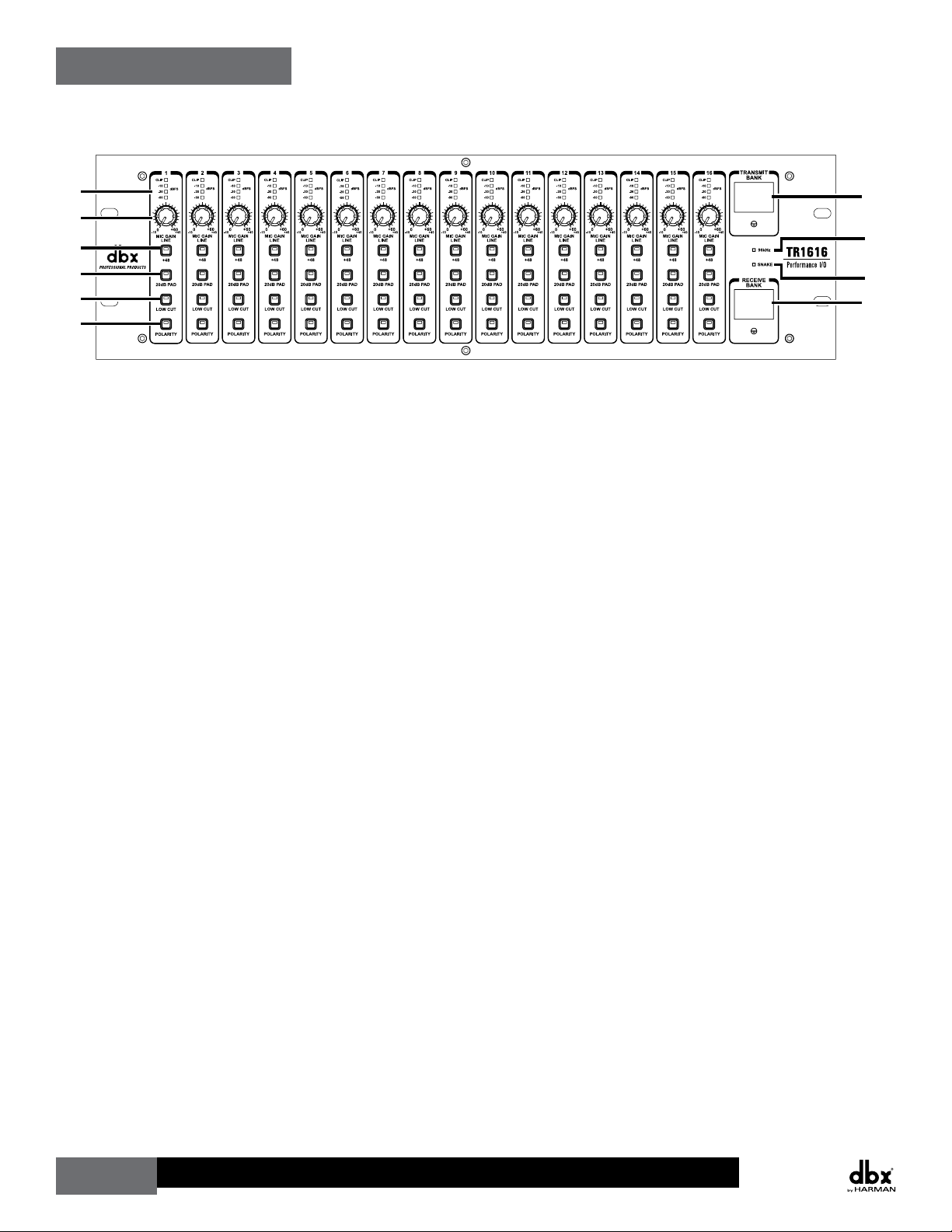
Front Panel
1
2
3
4
5
6
1. 4-Segment Input Meter
These meters display the input signal level for each channel.
2. GAIN Knob
These knobs adjust the input gain for each channel. The range of these controls is 0 dB
to +60 dB (XLR input) and -15 dB to +45 dB (1/4” input).
3. +48 Button
+48 Volts of phantom power is available for condenser microphones and direct boxes
which require it. These buttons enable and disable the phantom power for each channel.
The button’s LED will light when the function is engaged.
7
8
9
10
4. 20dB PAD Button
These buttons enable the 20dB pad for each channel, which can be used to prevent the
preamp input from being overdriven. The button’s LED will light when the function is
engaged.
5. LOW CUT Button
These buttons enable and disable the low cut filter for each channel. This filter is a low
cut filter with a cutoff frequency of 80 Hz. The button’s LED will light when the function
is engaged.
6. POLARITY Button
These buttons enable and disable the 1800 polarity inversion for each channel. The
button’s LED will light when the function is engaged.
7. TRANSMIT BANK Display
This dual 7-segment display shows which bank on the BLU link network the TR1616
is transmitting its audio on. Each bank consists of 16 channels. Each TR1616 on the
network must have a unique TRANSMIT BANK selected. The desired TRANSMIT BANK
can be selected by adjusting the slotted control below the display. See “Making
Connections–Cabling” > “BLU link” for further information on this display.
4
TR1616 Owner’s Manual
Page 11

8. 96 kHz LED
This LED will light when the 96 kHz button on the back panel of the TR1616 is engaged,
indicating the TR1616 is configured to clock to a BLU link signal operating at a 96 kHz
sampling rate. When the 96 kHz button is disengaged, the sample rate of the TR1616 is
48 kHz.
9. SNAKE LED
This LED will light when the Snake Enable button on the back panel of the TR1616 is
engaged, indicating the TR1616 has been configured for use in a TR1616 digital snake
network.
10. RECEIVE BANK Display
This dual 7-segment display shows the currently selected bank of BLU link channels
which will be received by the TR1616 and routed to the analog outputs. Each bank
consists of 16 channels. The desired RECEIVE BANK can be selected by adjusting the
slotted control below the display. See “Making Connections–Cabling” > “BLU link” for
further information on this display.
TR1616 Owner’s Manual
5
Page 12

Rear Panel
1
2
3
1. INPUTS
These combination analog input jacks accept: 1/4” or XLR type plugs, line level or mic
level signals, and balanced or unbalanced connections.
2. OUTPUTS
These XLR analog output jacks output a balanced analog signal, received and converted
from the BLU link audio network.
54 7 8 10 116 9
3. AC Power Inlet
Provides power to the TR1616 using the provided IEC type AC power cord. A fuse drawer
provides access to the fuse. Replace with same type fuse only.
4. ETHERNET Port
This port allows for future expansion of the TR1616’s feature set.
5. USB Port
Using a standard Mini USB cable, this port is used for connecting a PC for updating the
TR1616’s firmware.
6. 96 kHz Button
Engage this button when connecting to a BLU link network operating at a 96 kHz
sampling rate. Disengage this button when connecting to a BLU link network operating
at a 48 kHz sampling rate.
Note: BLU link supports 256 channels at 48 kHz and 128 channels at 96 kHz.
7. SNAKE IN Port
When using two or more TR1616s in a digital snake network, connect this Ethercon
connector to the SNAKE OUT port on the sending TR1616 device.
6
TR1616 Owner’s Manual
Page 13

8. SNAKE OUT Port
When using two or more TR1616s in a digital snake network, connect this Ethercon
connector to the SNAKE IN port on the receiving TR1616 device.
9. SNAKE ENABLE Button
When this button is engaged, the TR1616 will transmit and receive BLU link audio
through the SNAKE IN and SNAKE OUT ports. Engage this button on two TR1616s which
carry and receive the signal between the front of house and stage locations.
10. LOOP IN Port
Connect this Ethercon connection to the BLU link output of a sending BLU link
compatible device or to the BLU link LOOP OUT port of another TR1616.
11. LOOP OUT Port
Connect this Ethercon connector to the BLU link input of a receiving BLU link
compatible device or to the BLU link LOOP IN port of another TR1616.
TR1616 Owner’s Manual
7
Page 14

making connectionS–cabling
It is recommended that power on all interconnecting equipment be turned off before making
audio connections to the TR1616.
Power
Connect the included IEC power cable to this fused AC inlet. Connect the other end to an
available AC power outlet. The TR1616 does not have a power switch. An AC power strip or power
conditioner can be used for switching power to the TR1616 on and off.
Note: If the fuse becomes compromised, replace with the same type fuse only. See “Specifications”
for fuse information.
Analog Inputs
These combination inputs accept XLR or 1/4”
analog connections. Use the XLR inputs for
connecting low impedance microphones and DI
boxes and the 1/4” inputs for line level devices
with balanced or unbalanced connections. The
wiring conventions of these connectors are
shown to the right.
Tip Hot Pin 1 Ground
Ring Cold Pin 2 Hot
Sleeve Ground Pin 3 Cold
1/4” XLR
Note: All microphones and devices requiring phantom power must be connected using the XLR
input connections.
Analog Outputs
These XLR analog outputs provide balanced
audio connections. The wiring convention of
these connectors are shown to the right.
Pin 1 Ground
Pin 2 Hot
Pin 3 Cold
XLR
BLU link
The SNAKE IN, SNAKE OUT, LOOP IN, and LOOP OUT ports are all BLU link ports and require the
same type of cabling. BLU link is a proprietary point to point networking protocol that requires
CAT5e or better cable. The BLU link ports are auto sensing, so you can use either a straight
through cable (same termination on both ends) or crossover cable between them. The maximum
allowable cable length of a single BLU link connection is 100 m (328 ft). By closing the BLU link
ring, BLU link’s built-in fault tolerance feature can be utilized.
8
TR1616 Owner’s Manual
Page 15

Any of the CAT5e cable configurations shown in the below table can be used when making BLU
RJ-45
RJ-45
RJ-45
RJ-45
RJ-45
RJ-45
RJ-45
RJ-45
BLU link LOOP OUT to IN-->
SNAKE IN-->
<--SNAKE OUT
Powered
Wedge Monitor
Instrument
Instruments
<--BLU link LOOP IN
PMC16
TR1616
BLU link from SNAKE OUT (100 m/328 ft max)
BLU link to SNAKE IN (100 m/328 ft max)
Transmit Bank: 2
Receive Bank: 1
2
BLU link OUT to LOOP IN-->
OUT
IN
BLU link-->
RX: 1 or 2 RX: 1 or 2 RX: 1 or 2
link connections.
TIA/EIA 568A Straight Through TIA/EIA 568B Straight Through
(8-Position)
1 1
2 2
3 3
4 4
5 5
6 6
7 7
8 8
White / Green
Green
White / Orange
Blue
White / Blue
Orange
White / Brown
Brown
(8-Position)
(8-Position)
1 1
2 2
3 3
4 4
5 5
6 6
7 7
8 8
White / Orange
Orange
White / Green
Blue
White / Blue
Green
White / Brown
Brown
(8-Position)
TIA/EIA 568A Crossover TIA/EIA 568B Crossover
(8-Position)
Gr/Wh
1 1
Gr
2 2
Wh/Or
3 3
Bl
4 4
Wh/Bl
5 5
Or
6 6
Wh/Br
7 7
Br
8 8
(8-Position)
Wh/Or
Or
Gr/Wh
Wh/Br
Br
Gr
Bl
Wh/Bl
(8-Position)
Wh/Or
1 1
Or
2 2
Wh/Gr
3 3
Bl
4 4
Wh/Bl
5 5
Gr
6 6
Wh/Br
7 7
Br
8 8
(8-Position)
Wh/Gr
Gr
Wh/Or
Wh/Br
Br
Or
Bl
Wh/Bl
Note: The BLU link network ring must be closed for the BLU link fault tolerance feature to
work. The fault tolerance feature ensures audio will still pass through the network if one of the
cables in the BLU link network is compromised. This means that when TR1616s are being used
as a digital snake, the TR1616s on both sides of the snake connection must complete the BLU
link ring. If using a single TR1616 on either side of the snake connection and no other BLU link
devices are connected, such as PMC16s, the LOOP OUT port should be connected to the LOOP IN
port to close the BLU link ring, as shown below. See page 12 to see full diagram.
For more information on BLU link, please visit www.dbxpro.com.
and allows the built-in fault
tolerance feature to work)
(closes the BLU link ring
BLU link LOOP OUT
to LOOP IN-->
TR1616 Owner’s Manual
1
Mixer
Outputs
From Instruments
Transmit Bank: 1
Receive Bank: 2
TR1616
On Stage
01
02
SNAKE OUT-->
<--SNAKE IN
9
Page 16

applicationS
BLU link
<--To TR1616 LOOP IN
BLU link OUT-->
<--BLU link LOOP IN
Personal Monitoring w/dbx PMC16s
Recommended for:
• Small Performance Venues
• Portable Live Sound
• Houses Of Worship
• Rehearsal Spaces
FRONT OF HOUSE
Mixer
Outputs
Receive Bank: 1
1
1
Transmit Bank: 1
Transmit Bank: 1
Receive Bank: N/A
TR1616
01
01
BLU link LOOP OUT-->
10
TR1616 Owner’s Manual
Page 17

Key Points:
<--To TR1616 LOOP IN
BLU link OUT-->
• Up to 16 channels can be received at the PMC16s on stage from front of house.
• Up to 60 PMC16s can be connected to the network.
• System can be further expanded in the future if needed.
IN-->
BLU link
STAGE
Powered
Wedge Monitor
RX: 1 RX: 1 RX: 1
PMC16
OUT
IN
BLU link-->
Powered
Wedge Monitor
OUT
IN
PMC16
BLU link-->
Power SupplyPower SupplyPower Supply
Powered
Wedge Monitor
PMC16
BLU link Connection
Analog Connection
Legend
TR1616 Owner’s Manual
11
Page 18

16 x 16 Digital Snake w/Personal Monitoring
<--BLU link LOOP IN
BLU link OUT to LOOP IN-->
Recommended for:
• Small To Medium Performance Venues
• Portable Live Sound
• Houses Of Worship
Note: The BLU link ring in the below diagram is closed by connecting the #1 TR1616’s LOOP
OUT port to the LOOP IN port. However, it is also possible to close the BLU link ring without
using this extra cable connection. To do this, leave the snake mode disabled on the #1 TR1616
and make the following connections:
• #2 TR1616 SNAKE OUT > #1 TR1616 LOOP IN
• #1 TR1616 LOOP OUT > #2 TR1616 SNAKE IN
and allows the built-in fault
tolerance feature to work)
(closes the BLU link ring
BLU link LOOP OUT
to LOOP IN-->
FRONT OF HOUSE
From Instruments
On Stage
TR1616
1
Mixer
Outputs
Transmit Bank: 1
Receive Bank: 2
01
02
SNAKE OUT-->
<--SNAKE IN
BLU link to SNAKE IN (100 m/328 ft max)
BLU link from SNAKE OUT (100 m/328 ft max)
12
TR1616 Owner’s Manual
Page 19

Key Points:
<--BLU link LOOP IN
BLU link OUT to LOOP IN-->
• Up to 16 channels can be received at front of house from the stage.
• Up to 16 channels can be returned to the stage from front of house.
• Up to 60 PMC16s can be connected to the network.
• Although this diagram does not show it, the main mixer outputs could be connected
to the #1 TR1616 and then fed to the #2 TR1616 for feeding the amplifiers or
loudspeaker management processor for the main PA speakers.
• System can be further expanded in the future if needed.
SNAKE IN-->
<--SNAKE OUT
BLU link LOOP OUT to IN-->
STAGE
TR1616
2
Instruments
Powered
Wedge Monitor
RX: 1 or 2 RX: 1 or 2 RX: 1 or 2
PMC16
Transmit Bank: 2
Receive Bank: 1
Instrument
OUT
IN
BLU link-->
02
01
Powered
Wedge Monitor
OUT
PMC16
BLU link-->
Powered
Wedge Monitor
Instrument
IN
PMC16
BLU link Snake Connection
Power SupplyPower SupplyPower Supply
Instrument
Legend
BLU link Connection
Analog Connection
TR1616 Owner’s Manual
13
Page 20

32 x 32 Digital Snake w/Personal Monitoring
BLU link OUT to LOOP IN-->
Recommended for:
• Large Performance Venues
• Houses Of Worship
• Ensembles
• Orchestras
1
Mixer
Outputs
Transmit Bank: 1
Receive Bank: 3
From Instruments
TR1616
FRONT OF HOUSE
On Stage
01
2
03
<--BLU link LOOP OUT to LOOP IN
Transmit Bank: 2
Receive Bank: 4
From Instruments
TR1616
On Stage
02
04
BLU link to SNAKE IN (100 m/328 ft max)
BLU link from SNAKE OUT (100 m/328 ft max)
14
BLU link LOOP OUT to LOOP IN-->
TR1616 Owner’s Manual
Page 21

Key Points:
BLU link OUT to LOOP IN-->
• Up to 32 channels can be received at front of house from the stage.
• Up to 32 channels can be returned to the stage from front of house.
• Up to 60 PMC16s can be connected to the network
• Snake mode is enabled on the #2 and #3 TR1616s and disabled on the #1 and #4
TR1616s.
• Although this diagram does not show it, the main mixer outputs could be connected
to the #2 TR1616 and then fed to the #4 TR1616 for feeding the amplifiers or
loudspeaker management processor for the main PA speakers.
• System can be further expanded in the future if needed.
SNAKE IN-->
<--SNAKE OUT
BLU link LOOP OUT to IN-->
Power Supply
STAGE
BLU link LOOP OUT to LOOP IN
TR1616
3
Instruments
Powered
Wedge Monitor
RX: 1 RX: 1 RX: 1
PMC16
Transmit Bank: 3
Receive Bank: 1
Instrument
OUT
IN
BLU link-->
03
4
01
Instruments
Powered
Wedge Monitor
Instrument
OUT
PMC16
BLU link-->
Power SupplyPower Supply
TR1616
Transmit Bank: 4
Receive Bank: 2
IN
04
02
Powered
Wedge Monitor
Instrument
PMC16
BLU link Connection
BLU link Snake Connection
Analog Connection
Legend
TR1616 Owner’s Manual
15
Page 22

32 Channel BSS Soundweb London On-Ramp/Off-Ramp
Sources To
Analog Inputs
Sources To
Analog Inputs
Sources
Analog Outputs
To Destinations
Analog Outputs
To Destinations
Destinations
Recommended for:
• Large Performance Venues
• Houses Of Worship
• Any BLU link Compatible BSS Audio Soundweb London System Requiring Additional
Analog Inputs And/Or Outputs
Sources
32 CHANNEL ANALOG ON-RAMP FOR BLU LINK
COMPATIBLE BSS SOUNDWEB LONDON SYSTEM
Sources To
Analog Inputs
2
BLU link OUT to LOOP IN-->
Receive Bank: N/A
Transmit Bank: 2
02
01
TR1616
BLU link LOOP OUT to LOOP IN-->
<--BLU link LOOP OUT to BLU link IN)
BLU link
BLU-800
1
BLU-800
Sources To
Analog Inputs
3
Transmit Bank: 3
Receive Bank: N/A
TR1616
03
01
BLU link Connection
Analog Connection
Legend
16
TR1616 Owner’s Manual
Page 23

Key Points:
Sources To
Analog Inputs
Sources To
Analog Inputs
Sources
• Allows for easy analog audio connection to BSS Audio Soundweb London systems, due
to the TR1616’s combo (1/4” and XLR) inputs and XLR outputs, eliminating the need
to make special Phoenix fitted cables.
• TR1616s can easily be added to pre-existing BLU link compatible Soundweb London
systems with no additional hardware required.
• The two BSS BLU-800 processors (#1) occupy the first 16 channels of audio on the BLU
link network. The #2 TR1616 occupies channels 17-32 (BANK 2) and the #3 TR1616
occupies channels 33-48 (BANK 3) on the network.
• These two system diagrams illustrate two separate systems: one is using two TR1616s
for adding 32 channels of analog inputs to the BLU link network (on-ramp), the
other is using two TR1616s for adding 32 channels of analog outputs to the BLU link
network (off-ramp). However, the systems shown in these two diagrams can also be
thought of as one system, providing both on-ramp and off-ramp functionality at the
same time, as illustrated by the semi-transparent portions within each diagram.
• Systems can be further expanded in the future if needed.
32 CHANNEL ANALOG OFF-RAMP FOR BLU LINK
COMPATIBLE BSS SOUNDWEB LONDON SYSTEM
2
BLU link OUT to LOOP IN-->
Analog Outputs
To Destinations
Transmit Bank: N/A
Receive Bank: 1
TR1616
BLU link LOOP OUT to LOOP IN-->
BLU link
1
02
3
01
<--BLU link LOOP OUT to BLU link IN)
BLU-800
BLU-800
Transmit Bank: N/A
Receive Bank: 1
Analog Outputs
To Destinations
03
01
TR1616
BLU link Connection
Analog Connection
Destinations
Legend
TR1616 Owner’s Manual
17
Page 24

operating inStructionS
Setting BLU link Receive & Transmit Banks
To set the BLU link receive and transmit channel banks, use a small flat-head screwdriver or your
fingernail to turn the slotted controls beneath the RECEIVE BANK & TRANSMIT BANK displays.
Note: Multiple TR1616s in a network can be assigned to the same RECEIVE BANK, if the
application requires it. However, each TR1616 on the network must have its own unique TRANSMIT
BANK selected. See “Applications” for examples of channel bank assignments.
BLU link supports 256 channels at 48 kHz and 128 channels at 96 kHz. The below table shows
which range of channels are available within each BLU link channel bank and which channels
are supported when operating at a 96 kHz sample rate.
TR1616 BLU link Bank/Channel Table
Channel Bank Channels Available In Bank Supported Sample Rates
1 1-16 48 kHz/96 kHz
2 17-32 48 kHz/96 kHz
3 33-48 48 kHz/96 kHz
4 49-64 48 kHz/96 kHz
5 65-80 48 kHz/96 kHz
6 81-96 48 kHz/96 kHz
7 97-112 48 kHz/96 kHz
8 113-128 48 kHz/96 kHz
9 129-144 48 kHz
10 145-160 48 kHz
11 161-176 48 kHz
12 177-192 48 kHz
13 193-208 48 kHz
14 209-224 48 kHz
15 225-240 48 kHz
16 241-256 48 kHz
Note: Setting both the TRANSMIT BANK and RECEIVE BANK to the same channel allows signal
pass-through of the analog inputs to the analog outputs. In certain applications this may be
a desirable feature. For example, if you wanted to incorporate dbx PMC16 personal monitor
controllers into your existing system using a traditional analog snake, it is possible to connect
the analog snake to a single TR1616 at the front of house position (instead of straight to the
mixing console). The TR1616 could then pass the analog signals out to the mixing console
through the XLR outputs and out to the PMC16s on stage via BLU link.
18
TR1616 Owner’s Manual
Page 25

BLU link Status Indicators
The dual 7-segment displays provide information about BLU link connections as described below.
TRANSMIT BANK (BLU LINK OUT)
Flashing Display Segments: When this display
ashes, an invalid BLU link connection is detected
16
.
NOTE: The TRANSMIT BANK display indicates cable status for the LOOP
OUT port, regardless of snake mode.
at the LOOP OUT port.
DOT: When the dot segment is lit, there is a valid
BLU link connection detected at the LOOP OUT port.
16
.
NOTE: The RECEIVE BANK display indicates cable status for the LOOP IN
port when snake mode is disabled. When snake mode is enabled, the
RECEIVE BANK display indicates cable status for the SNAKE IN port
RECEIVE BANK (BLU LINK IN)
Flashing Display Segments: When this display
ashes, an invalid BLU link connection is detected
at the LOOP IN or SNAKE IN port.
DOT: When the dot segment is lit, there is a valid
BLU link connection detected at the LOOP IN port
or at the SNAKE IN port.
Examples
• The TR1616 display will flash when an invalid BLU link connection is detected, such as
when a BLU link IN is connected to another BLU link IN.
• The TRANSMIT BANK dot on the #1 TR1616 in the example set up on page 12 would
not illuminate if there were no path connecting the #1 TR1616’s LOOP OUT to LOOP IN.
The signal flow diagrams below show how BLU link signals are redirected depending on the Snake
Enable switch position.
Snake Disabled Snake Enabled
TR1616 Owner’s Manual
19
Page 26

TR1616 Preamp Setup
1. Start with all <MIC GAINS> set to the full counterclockwise position and all front
panel buttons disengaged (LEDs off).
2. Connect each instrument/source to the TR1616 using either the 1/4” input or XLR
input for each channel.
3. Engage the <+48> buttons on any channels which require phantom power, such as
active direct boxes and condenser microphones.
Note: All devices connected to the TR1616 which require phantom power must be
connected using the XLR connections.
4. Engage the <POLARITY> buttons on any channels which require it, such as the bottom
microphone of a top/bottom dual mic’ed snare pair.
5. With source signal present, adjust the first channel’s <MIC GAIN> knob so that the -10
dBFS LED barely lights and the CLIP LED does not.
6. Repeat step 5 for each channel. If a source causes one of the TR1616’s inputs to clip
when the <MIC GAIN> knob is all the way down, engage the <20dB PAD> button for
the channel and then complete step 5.
20
TR1616 Owner’s Manual
Page 27

firmWare updateS
The firmware in the TR1616 is updatable via the USB port. Available firmware updates can be
downloaded from www.dbxpro.com. The Firmware Updater application for the TR1616 requires a
®
Windows
To perform a firmware update:
1. Download the Firmware Updater application from www.dbxpro.com.
2. Follow the on-screen instructions to install the Firmware Updater application.
3. Launch the Firmware Updater application.
4. Follow the on-screen instructions to complete the firmware update procedure.
PC.
TR1616 Owner’s Manual
21
Page 28

block diagram
22
TR1616 Owner’s Manual
Page 29

dimenSionS
6.950
5.745
0.125
5.250
17.370
19.000
TR1616 Owner’s Manual
23
Page 30

SpecificationS
ANALOG INPUTS
Number of Inputs: 16
Connectors: Combination Female XLR and 1/4” Jack
Type: Electronically balanced, RF Filtered
Impedance: XLR input: 3kΩ,
1/4” input: 20kΩ balanced, 10kΩ unbalanced
Maximum Input Level: XLR Input: +18dBu at minimum gain
1/4” Input: +33dBu at minimum gain
Gain: XLR Input: 0 to +60dB
1/4” Input: -15 to +45dB
EIN: -125dBu, 22Hz-22kHz, 150Ω source impedance
CMRR: >40dB, typically 55dB, 22Hz-22kHz
Dynamic Range: 110dB unweighted, 113dB A-weighted
Frequency Response: 10Hz to 40kHz, +/- 0.25dB at 96kHz
10Hz to 20kHz, +/- 0.25dB at 48kHz
THD+N: Typically 0.002% at 1kHz, 0dBu XLR input, gain set to minimum
Interchannel Crosstalk: <100dB, 22Hz to 22kHz
ADC Latency: 37/Fs (0.77msec at 48kHz)
Phantom Power: +48VDC, applied to XLR pins 2 and 3 through 6.81k resistors
Pad: 20dB
Low Cut Filter: 2-pole Butterworth filter at 80Hz
Polarity: Normal or Reverse
ANALOG OUTPUTS
Number of Outputs: 16
Connectors: Male XLR
Type: Cross-Coupled Electronically balanced, RF Filtered
Impedance: 40Ω balanced, 20Ω unbalanced
Maximum Output Level: +20dBu into 2kohm load or greater
Dynamic Range: 112dB unweighted, 115dB A-weighted
Frequency Response: 10Hz to 40kHz, +/- 0.25dB at 96kHz
10Hz to 20kHz, +/- 0.25dB at 48kHz
THD+N: Typically 0.006% at 1kHz, 0dBu output
Interchannel Crosstalk: <-100dB, 22Hz to 22kHz
DAC Latency: 29/Fs (0.60msec at 48kHz)
24
TR1616 Owner’s Manual
Page 31

SYSTEM
Sample Rate: 48kHz or 96kHz
Converter Wordlength: 24 bits
DSP Wordlength: 32 bit floating point
FRONT PANEL INDICATORS
LED Meter: Clip (-3dBFS), -10dBFS, -20dBFS, -50dBFS (dBFS = dB Full Scale)
96kHz: Illuminated for 96kHz, off for 48 kHz
Snake: Illuminated for Snake function
BLU-LINK AUDIO NETWORK
Connectors: 2x Ethercon lockable RJ45 Ethernet connectors
Maximum Cable Length: 100m/328ft on Category 5e cable between devices
Maximum number of nodes: 60
Maximum number of channels: 256 at 48kHz, 128 at 96kHz
Latency: 11/Fs (0.23msec at 48kHz)
Pass Through Latency: 4/Fs (0.08msec at 48kHz)
USB PORT
Connector: Mini-B
ETHERNET
Connector: RJ45
Maximum Cable Length: 100m/328ft on Category 5e cable between devices
POWER AND DIMENSIONS
Power Requirements: 100VAC-240VAC, 50/60Hz, 55 watts
Fuse: 1.6A 250V Timelag Hi Brk
Rack Unit: 3U
Dimensions: 5.25” (H) x 19” (W) x 6.25” (D)
133.4 mm (H) x 482.6 mm (W) x 158.8 mm (D)
Weight: 9.6 lb (4.4 kg)
Shipping Weight: 11.3 lb (5.1 kg)
TR1616 Owner’s Manual
25
Page 32
8760 South Sandy Parkway
Sandy, Utah 84070
PH (801) 566-8800
FAX (801) 566-7005
http://www.dbxpro.com
dbx® is a registered trademark
of Harman
Copyright - Harman
TR1616 Owner’s Manual 5035742-A
Printed in China
 Loading...