

Page 1

SC32/SC64 Help
Page 2

Page 3

iii
Table Of Contents
SC 32 / SC 64 ...................................................................................................... 1
SC 32 / SC 64................................................................................................... 1
Overview - SC 32 / SC 64................................................................................. 2
Philosophy - SC 32 / SC 64 .............................................................................. 3
Front Panel ....................................................................................................... 5
Controls/LEDs - SC 32 / SC 64 ..................................................................... 5
Back Panel........................................................................................................ 7
Back Panel Connections - SC 32 / SC 64 ..................................................... 7
Card Slots - SC 32 / SC 64............................................................................ 9
Ethernet Connectivity - SC 32 / SC 64 ........................................................ 13
RS-232 Connectivity - SC 32 / SC 64.......................................................... 14
ZC Inputs 1-6 and 7-12 - SC 32 / SC 64 ..................................................... 15
Option Slots - SC 32 / SC 64....................................................................... 16
Control Inputs - SC 32 / SC 64.................................................................... 17
Relay Input - SC 32 / SC 64 ........................................................................ 18
OPTO Connection - SC 32 / SC 64 ............................................................. 19
Logic Outputs - SC 32 / SC 64 .................................................................... 20
Power Input - SC 32 / SC 64 ....................................................................... 21
Hardware ........................................................................................................ 22
Spec Sheet - SC 32 / SC 64........................................................................ 22
Device Window - SC 32 / SC 64 ..................................................................... 28
Device Window - SC 32 / SC 64.................................................................. 28
Page 4

SC32/SC64 Help
iv
Right Click Device Window Menu - SC 32 / SC 64...................................... 30
Menus - SC 32 / SC 64 ............................................................................... 31
Device Presets - SC 32 / SC 64 ................................................................ 167
Processing Modules SC 32 / SC 64 .......................................................... 168
Creating Panel Presets - SC 32 / SC 64 ....................................................... 217
Scheduling - SC 32 / SC 64 .......................................................................... 218
Wiring............................................................................................................ 219
Wiring - SC 32 / SC 64 .............................................................................. 219
Ethernet - SC 32 / SC 64........................................................................... 222
Zone Controllers - SC 32 / SC 64.............................................................. 223
RS-232 - SC 32 / SC 64 ............................................................................ 224
Zone Controller Distance Limitations - SC 32 / SC 64............................... 225
Zone Controller DIP Switch - SC 32 / SC 64 ............................................. 227
Page 5

1
SC 32 / SC 64
SC 32 / SC 64
Overview
Philosophy
Page 6

SC32/SC64 Help
2
Overview - SC 32 / SC 64
Based on the principles of the dbx Zone processing products, the SC 32 and SC
64 Digital Matrix Processors are the new flagship products for digital matrix
processing. Wizard driven configuration using HiQnet System Architect™ makes
unprecedented DSP power, incredible routing flexibility and a rich palette of
processing tools accessible with the minimum of training. The SC 32 and SC 64
represent the professional choice of foundation on which to build even the most
demanding integrated system.
The SC 32 / SC 64 has a total analog I/O count of 32 (the SC 64 has 64),
configurable in banks of eight. Eight analog input cards and eight analog output
cards facilitate five different fully loaded configurations (nine for the SC 64).
Analog input cards accommodate a wide range of sources with mic/line switching
and phantom power per input. Two high-speed options slots provide facility for
adding forthcoming high bandwidth audio transport I/O cards. All of these
features are housed in a sleek 2U rack chassis.
With dedicated DSP for common processing functions and insert positions for
specialized processing, the SC 32 / SC 64 offers many processing functions
including Advanced Feedback Suppression (AFS™), Ambient Noise
Compensation (ANC), priority ducking, parametric equalization (PEQ), delay and
dynamics. The SC 32 and SC 64 have a diverse range of control options
including HiQnet System Architect™ custom control panels, Ethernet, serial,
contact closure, the popular ZC wall controllers and even automatically
scheduled events. With so many methods of control, an SC system can truly be
tailored to suit the needs and technical expertise of even the most scrutinizing
contractor.
0.4
Page 7

SC 32 / SC 64
3
Philosophy - SC 32 / SC 64
The memory structure of the SC 32 / SC 64 consists of Attributes and Presets.
Attributes
Device attributes are global functions that affect the entire device such as the
sample rate. Most of the SC 32 / SC 64 attributes are found in the Utilities section
of the Tools menu (see Utilities) in the Device Window. There are some attributes
that are managed directly from the Device Window, like Mutes and Solos (see
Device Window below).
Device Presets
A Device Preset is a snapshot of the current state of the SC 32 or SC 64. It
includes the parameter values of all of the Processing Modules in the current
configuration. Device Presets are managed from the Device Window using the
Preset bar (see Device Window). The Device Window shows the Processing
Modules prominently as icons, where each icon represents the Processing
Module in that signal path location. Double clicking on these icons allows the
user access to the underlying parameters of these modules. Saving a Device
Preset saves every parameter of all processing functions shown.
Files
Besides the Device Presets and Attributes that are stored on the SC device,
System Architect provides additional file types that can be saved to the
computer, the Device file and Venue file. The Device file captures the entire unit
including all Presets stored and all Attributes of that device. The Venue File is the
final extension; the Venue file is a snapshot of the entire Venue with the current
Preset and Attributes of every device in the venue. The Venue file is saved from
the File menu of the Venue View.
Device Window
All Presets, Processing Functions and their Parameters, as well as device
Attributes of the SC 32 / SC 64 are accessed via the Device Window. In addition
to these functions, the Device Window File Menu also provides the capability of
saving Device files.
Page 8

SC32/SC64 Help
4
Page 9

SC 32 / SC 64
5
Front Panel
Controls/LEDs - SC 32 / SC 64
Front Panel LCD Display
Gives information relating to network configuration, current time and date, HiQnet
Node Address, SC firmware version and device status
Page / Select Buttons
Allow front panel navigation
RS-232 LED
Indicates a connection to the RS-232 port
Clip LED
Gives global DSP clip indication
Sync LED
Link / activity connection
Power LED
Power present indication
Card Position Label
I/O Card Type Indication
Analog or digital, input or output indication per card position
Clip LED
Analog clip indication per channel for inputs and outputs (19.9dB)
Sync LED
Digital Sync indication per card position for SC Digital Input / Output Cards
(coming soon)
Phantom Power LED
Phantom Power indication per channel for SC Analog Input Cards
Signal LED
Signal present indication per channel for inputs and outputs (-40dB)
Product Information
Product model and description
Page 10

SC32/SC64 Help
6
Page 11

SC 32 / SC 64
7
Back Panel
Back Panel Connections - SC 32 / SC 64
Card Slots
Ethernet Connectivity
RS-232 Connectivity
ZC Inputs
Option Slots
Control Inputs
Relay Input
OPTO Connection
Logic Outputs
Power Input
Option Slots
High-speed Option Slots accommodating high-bandwidth networked audio option
cards (coming soon)
SC 32 - One Option Slot
SC 64 - Two Option Slots
Power Connector
IEC power connector
Fuse
Field-serviceable fuse
Control Inputs
Allow up to eight contact closures, faders or rotary potentiometers to used to
control HiQnet™ parameters
Page 12

SC32/SC64 Help
8
Relay
Integrated relay with Normally Open (NO) and Normally Closed (NC) terminals
driven from HiQnet™ parameters
Opto
Opto-isolator conducts when device is powered and functioning correctly
Logic Outputs
Allow SC 32 / SC 64 to control up to six LED's or relays
Ethernet Connectors
Ethernet connectors for SC 32 / SC 64 configuration, control and monitoring as
well as integration of third party control systems using IP control (Integrated
Ethernet switch allows daisy-chaining of devices within a rack)
RS-232 Port
Serial port for integration with third party control systems
ZC Ports
Allow connection of up to 12 ZC controllers (six per port) for control of HiQnet
parameters
Card Position Label
Audio Connector
Balanced connections for installed I/O card
I/O Card Type Indication
Analog Input LED/Connector - Green
Analog Output LED/Connector - Orange
Digital* Input LED/Connector - Blue (coming soon)
Digital* Output LED/Connector - Yellow (coming soon)
*AES/EBU and S/PDIF
Page 13

SC 32 / SC 64
9
Card Slots - SC 32 / SC 64
Card Slots - SC 32 / SC 64
Configurable in banks of 8, the SC 32 and 64 provide up to 32 and 64 channels
of audio respectively. Eight card slots facilitate five different fully loaded
configurations (nine in the SC 64). The Analog Input card accommodates a wide
range of sources with mic/line switching and phantom power per input.
I/O Card Type Indication
Analog Input LED/Connector - Green
Analog Output LED/Connector - Orange
Digital* Input LED/Connector - Blue (coming soon)
Digital Output LED/Connector - Yellow (coming soon)
*AES/EBU and S/PDIF
Card Types
Pin Out
Page 14

SC32/SC64 Help
10
Card Types - SC 32 / SC 64
The SC 32/64 accepts Analog Input and Analog Output cards, carrying 8
channels per card.
I/O Card Type Indication
Analog Input LED/Connector - Green
Analog Output LED/Connector - Orange
Digital* Input LED/Connector - Blue (coming soon)
Digital* Output LED/Connector - Yellow (coming soon)
*AES/EBU and S/PDIF
Page 15
SC 32 / SC 64
11
Pin out - SC 32 / SC 64
Overview:
The dbx SC 32 and SC 64 Analog Input and Analog Output Cards are designed
to populate any of the four or eight card slots on the dbx SC 32 and SC 64
devices respectively. These analog cards enable dbx SC devices to receive
microphone / line level signals and send line level signals.
The dbx SC 32 and SC 64 Analog Input Cards offer Phantom Power,
configurable per channel and software controlled analog gain in 6dB steps from
0dB to 48dB.
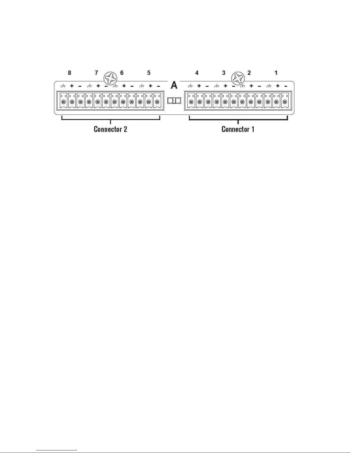
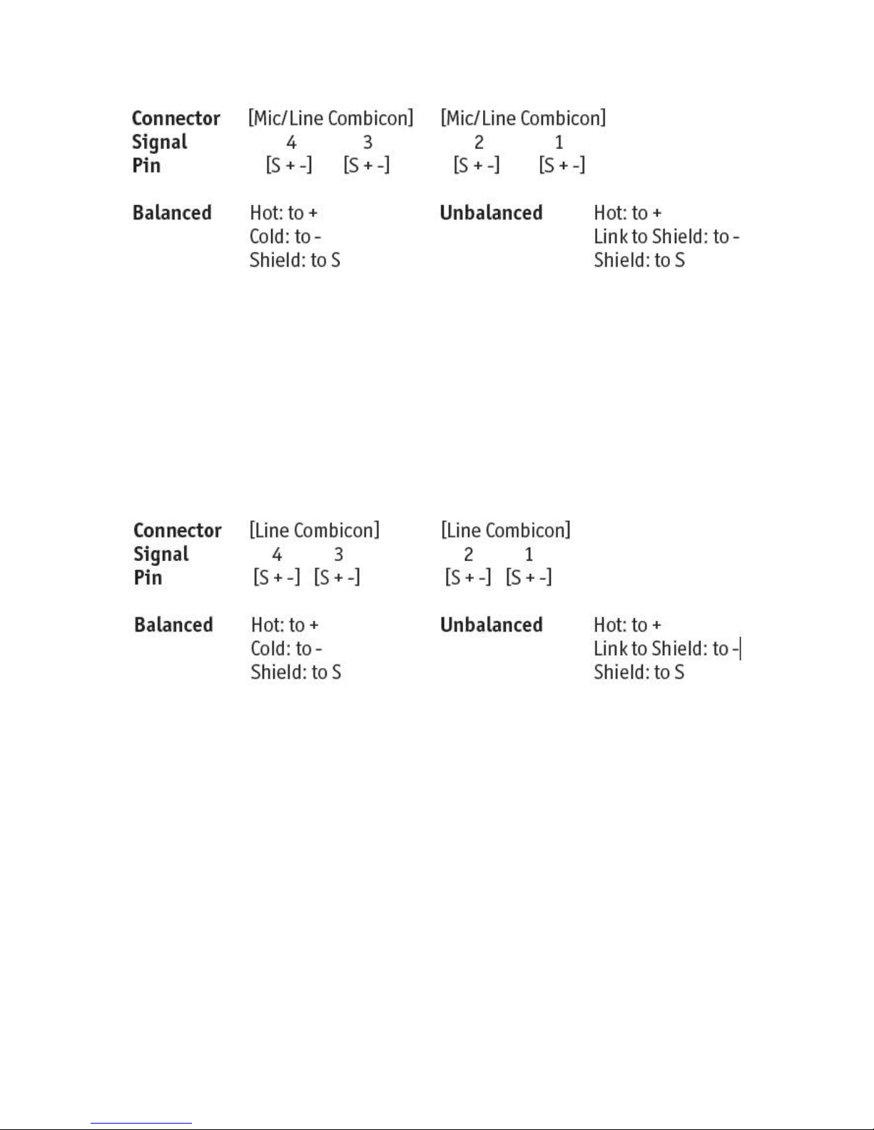
The Analog Cards each have two Combicon connectors which are used as
follows:
Analog Input Card :
• Connector 1
o Balanced / Unbalanced Audio, Channel 1 - Mic/Line
o Balanced / Unbalanced Audio, Channel 2 - Mic/Line
• Connector 2
o Balanced / Unbalanced Audio, Channel 3 - Mic/Line
o Balanced / Unbalanced Audio, Channel 4 - Mic/Line
Page 16
SC32/SC64 Help
12
Analog Output Card:
• Connector 1
o Balanced / Unbalanced Audio, Channel 1 - Line
o Balanced / Unbalanced Audio, Channel 2 - Line
• Connector 2
o Balanced / Unbalanced Audio, Channel 3 - Line
o Balanced / Unbalanced Audio, Channel 4 - Line
Page 17

SC 32 / SC 64
13
Ethernet Connectivity - SC 32 / SC 64
Ethernet Connectors
Ethernet connectors for SC 32 / SC 64 configuration, control and monitoring as
well as integration of third party control systems using IP control (Integrated
Ethernet switch allows daisy-chaining of devices within a rack).
Page 18

SC32/SC64 Help
14
RS-232 Connectivity - SC 32 / SC 64
RS-232 Port
Serial port for integration with third party control systems.
Page 19

SC 32 / SC 64
15
ZC Inputs 1-6 and 7-12 - SC 32 / SC 64
ZC Ports
Allow connection of up to 12 ZC controllers (six per port) for control of HiQnet
parameters.
Page 20

SC32/SC64 Help
16
Option Slots - SC 32 / SC 64
Option Slots
High-speed Option Slots accommodating high-bandwidth networked audio option
cards. (coming soon)
SC 32 - One Option Slot
SC 64 - Two Option Slots
Page 21

SC 32 / SC 64
17
Control Inputs - SC 32 / SC 64
Control Inputs
Allows up to eight contact closures for control of HiQnet™ parameters.
Page 22

SC32/SC64 Help
18
Relay Input - SC 32 / SC 64
Relay
Integrated relay with Normally Open (NO) and Normally Closed (NC) terminals
driven from HiQnet™ parameters.
Page 23

SC 32 / SC 64
19
OPTO Connection - SC 32 / SC 64
Opto
Opto-isolator conducts when device is powered and functioning correctly.
Page 24

SC32/SC64 Help
20
Logic Outputs - SC 32 / SC 64
Logic Outputs
Allow SC 32 / SC 64 to control up to six LEDs or relays.
Page 25

SC 32 / SC 64
21
Power Input - SC 32 / SC 64
Power Connector
IEC power connector.
Page 26

SC32/SC64 Help
22
Hardware
Spec Sheet - SC 32 / SC 64
FRONT PANEL INDICATORS
Per channel:
48V (yellow), CLIP (red), SIGNAL (green)
Per 8 channel bank:
IN (green), OUT (orange), D-IN (blue), D-OUT (yellow), SYNC (green)
Other:
16x2 LCD display, PAGE button (orange), SELECT button (green), CLIP (red),
LINK/ACT (green), RS-232 (green), POWER (green)
ANALOG INPUTS
Connectors:
Phoenix/Combicon, 3.5mm pitch
Channels:
Eight per card
Line/Mic Inputs:
Nominal gain 0 dB Electronically switchable to +6, +12, +18, +24, +30, +36, +42,
+48 dB
Type:
Electronically balanced, RF Filtered
Input Impedance:
3.5 k
Maximum Input Level:
+20 dBu
Noise Floor:
-92 dBu "A" weighted
Page 27

SC 32 / SC 64
23
-90 dBu unweighted, 20 Hz - 20 kHz
Dynamic Range:
113 dB "A" weighted, 20 Hz - 20 kHz
110 dB unweighted, 20 Hz - 20 kHz
CMRR:
> 40 dB typical, >50 dB at 1 kHz
EIN:
< -119 dBu unweighted, 20 Hz - 20 kHz, 150 W source impedance
Phantom Power:
+48 VDC selectable per input
A/D Latency:
12/Fs
ANALOG OUTPUTS
Connectors:
Phoenix/Combicon, 3.5mm pitch
Channels:
Eight per card
Type:
Electronically balanced, RF Filtered
Impedance:
44
Maximum Output Level:
+20 dBu
Noise Floor:
-92 dBu "A" weighted
-89 dBu unweighted, 20 Hz - 20 kHz
Page 28

SC32/SC64 Help
24
Dynamic Range:
112 dB "A" weighted
109 dB unweighted, 20 Hz - 20 kHz
D/A Latency:
10.4/Fs
SYSTEM PERFORMANCE
Dynamic Range:
110 dB "A"weighted
107 dB unweighted, 20 Hz to 20 kHz
Frequency Response:
20 Hz - 20 kHz, +0/-0.5 dB
THD+N:
0.0045% 0 dBu input, 1 kHz, 0 dB input gain
0.0065% 0 dBu input, 20 Hz - 20 kHz, 0 dB input gain
Inter-channel crosstalk:
> 90 dB typically, 20 Hz - 20 kHz
Internal Processing:
32 bit floating point
Internal Sample Rate:
48 kHz
Latency:
1.82 msec analog input to analog output
2.25 msec analog input to analog output with a mono mid-mixer
CONTROL INPUTS
Page 29

SC 32 / SC 64
25
Connector:
Phoenix/Combicon, 3.5mm pitch
Number:
8
Control Voltage Input:
0 to 4.5 VDC
Control Line Impedance:
4.7 k to +5 VDC
ZONE CONTROLLER INPUTS
Connectors:
RJ-45
Number:
2 connectors with 6 channels per connector for a total of 12 inputs
Usage:
For use with dbx ZC wall controllers
LOGIC OUTPUTS
Connector:
Phoenix/Combicon, 3.5mm pitch
Number:
6
Logic Output Voltage:
0 or +5 V unloaded
Logic Output Impedance:
440
Logic Output Current:
10 mA source, 60 mA sink
Page 30

SC32/SC64 Help
26
RELAY CONTACT CLOSURE
Connector:
Phoenix/Combicon, 3.5mm pitch
Contacts:
Common (C), Normally Open (NO), Normally Closed (NC)
Contact Rated Load:
0.3A at 125VAC, 1A at 30VDC
WATCHDOG OUTPUT
Connector:
Phoenix/Combicon, 3.5mm pitch
Type:
Opto-isolated
Output Current:
14 mA max
Withstanding Voltage:
80 V max (off)
Series Impedance:
220 isolated
MISCELLANEOUS
Power Requirements:
100 V to 240 VAC, 50/60 Hz
75 Watts for SC32, 120 Watts for SC64
Page 31

SC 32 / SC 64
27
BTU Rating:
256 BTUs maximum for SC 32, 409 BTUs maximum for SC 64
Dimensions:
3.5" tall x 19" wide x 15" deep
Weight:
SC 32: 15.7 pounds (with all audio cards installed)
SC 64: 18.9 pounds (with all audio cards installed)
dbx incorporates high quality mechanical fans in some products. All mechanical
fans have a limited life expectancy. We recommend annual inspection of fans for
dust occlusion and excessive noise. Fan assemblies should be replaced after six
to ten years of use. Environmental factors such as elevated temperature, dust,
and smoke can adversely affect fan life. Systems exposed to these conditions
should be inspected more frequently. Fan replacement can be performed either
at the factory or by an experienced technician in the field. Please contact dbx
Technical Support for more information on purchasing replacement parts or
product service. dbx has a policy of continued product improvement and
accordingly reserves the right to change features and specifications without prior
notice.
Page 32

SC32/SC64 Help
28
Device Window - SC 32 / SC 64
Device Window - SC 32 / SC 64
The Device Window (shown below) provides a graphical representation of the
processing occurring in the SC 32 / SC 64 unit. It also gives complete access to
a variety of tools that can be used to save or change the SC device.
Menus
The Menu Bar, along the top of the Device Window, offers a considerable
amount of control to the user. From this Menu Bar, Device files can be saved
and/or recalled. The Tools pull-down menu provides access to the Processing
Wizard that is used to change the device processing configuration as well as
Utilities where a majority of the SC attributes are shown and can be manipulated.
Presets
The Preset Tool located directly below the Menu Bar is used to Store and Recall
Presets to and from the SC device.
Processing Modules
Each Processing Module in the signal path of the SC 32 / SC 64 is displayed as
Page 33

SC 32 / SC 64
29
an icon in the Device Window. These icons are designed to give a representation
of the processing that is occurring. Processing can be broken down into Input
and Output processing.
Input Processing
The input processing consists of a router, a delay, a 4-band parametric equalizer,
a gate and two insert positions.
Output Processing
The output processing consists of a router, an insert position, a band-pass filter,
a 6-band parametric equalizer, a limiter, a delay and a mute.
Meters
Four meters at the top of the Device Window represent input and output levels
throughout the signal path. The signal path represented by these meters is
determined by what input and output Processing Modules are selected at that
time.
Page 34

SC32/SC64 Help
30
Right Click Device Window Menu - SC 32 / SC 64
When the user right clicks on the toolbar of the Device Window , the following
menu appears
Copy allows the user to copy all the settings within a particular Device Window
Paste allows the user to apply copied settings to different Device Windows
Copy HiQnet Information allows the user to copy device and string information
used for programming third party control systems.
Dock docks the Device Window into the System Architect's main window.
Page 35

SC 32 / SC 64
31
Menus - SC 32 / SC 64
Menus - SC 32 / SC 64
At the top of the Device Window are the available menus.
File
Edit
View
Tools
Help
Selecting one of the above menus will open a menu of options within that menu.
Page 36

SC32/SC64 Help
32
File Menu - SC 32 / SC 64
The File menu allows user access to store and recall program files.
Open allows you to open Device Files.
Save allows you to save Device Files.
Close will close the Device Window.
Page 37

SC 32 / SC 64
33
Edit Menu - SC 32 / SC 64
The Edit menu allows copy and paste functions.
Page 38

SC32/SC64 Help
34
View - SC 32 / SC 64
The View menu allows the user to dock windows including the Device Window.
While docked, the individual menus are selected using tabs across the top. Click
the view link on the menu bar.
Click on the dock selection. For example - A floating Device Window will look like
the image below. .
When the Device Window is docked, it will appear as seen in the following
image.
Page 39

SC 32 / SC 64
35
This can be helpful when switching from editor to editor during programming.
Page 40

SC32/SC64 Help
36
Tools Menu - SC 32 / SC 64
Tools - SC 32 / SC 64
The Tools Menu located on the Menu bar of the device view (or the main venue
view when the device is docked) contains most of the tools needed to configure
your device.
The Tools menu contains the following:
Hardware Configuration
Wizards
Utilities
Input Card Setup
Priority Mix Controls
I/O Card Meters
Page 41

SC 32 / SC 64
37
Hardware Configuration - SC 32 / SC 64
Hardware Configuration - SC 32 / SC 64
The Hardware Configuration menu allows you to access Card Configuration and
Peripheral Configuration.
Card Configuration allows you to specify the input/output card configuration of an
offline SC 32 or SC64.
Peripheral Configuration allows you to choose the Zone Controllers, Control
Inputs, Logic Outputs and Relay use associated with the SC 32 and SC 64.
Card Configuration
Peripheral Configuration
Page 42

SC32/SC64 Help
38
Card Configuration - SC 32 / SC 64
The SC 32 and SC 64 may come loaded in the following analog configurations:
SC 32: 8 x 0, 8 x 8, 8 x 16, 8 x 24, 16 x 0, 16 x 8, 16 x 16, 24 x 0, 24 x 8, 32 x 0,
0 x 8, 0 x 16, 0 x 24 and 0 x 32.
SC 64: 8 x 0, 8 x 8, 8 x 16, 8 x 24, 8 x 32, 8 x 40, 8 x 48, 8 x 56, 16 x 0, 16 x 8,
16 x 16, 16 x 24, 16 x 32, 16 x 40, 16 x 48, 24 x 0, 24 x 8, 24 x 16, 24 x 24, 24 x
32, 24 x 40, 32 x 0, 32 x 8, 32 x 16, 32 x 24, 32 x 32, 40 x 0, 40 x 8, 48 x 16, 56 x
0, 56 x 8, 0 x 8, 0 x 16, 0 x 24, 0 x 32, 0 x 40, 0 x 48, 0 x 56, 0 x 64.
Analog cards are available in two options, 8 analog input channels or 8 analog
output channels.
The SC 32 and SC 64 must be purchased in one of the previous configurations.
When the SC 32 and SC 64 are discovered by System Architect, the device and
it's currently loaded cards will automatically appear in the device and this step will
not be required.
When designing a system with an SC 32 or SC 64 in offline mode, you will need
to complete the following steps to properly configure your install. The device will
appear as 16 x 16 for the SC 32 and 32 x 32 for the SC 64 by default when
inserted into the Venue View.
Click on the Tools Menu as seen below.
Move your mouse over the Hardware Configuration option.
A fly out menu will appear.
Click on the Card Configuration option.
Page 43

SC 32 / SC 64
39
The Card Configuration window will appear.
The Card Configuration window contains card slot dropdown menus where you
may choose the card that will be populated into the SC 32 and SC 64.
The SC 32 will have Card Slots "A" through "D" available and the SC 64 will have
Card Slots "A" through "H" available.
From each of the slot options seen here you will choose one of the following:
8 Ch. Analog In, 8 Ch. Analog Out or Empty.
Page 44

SC32/SC64 Help
40
(NOTE: The factory will populate the cards with Inputs first starting in the Bottom
Right physical card slot "A" and then populate the rest of the slots "B", "C" and
"D" ending with output cards if used).
Page 45

SC 32 / SC 64
41
Peripheral Configuration - SC 32 / SC 64
The SC 32 and SC 64 have a great number of peripheral device controls that
may be used. These options include Zone Controllers (ZC), Control Inputs, Logic
Outputs and a Relay connection.
When the SC 32 and SC 64 are discovered by System Architect, they WILL NOT
automatically detect peripheral device connections! The peripheral configuration
step will have to be completed with each device design containing direct
peripheral connections.
To access the Peripheral Configuration simply click on the Tools Menu as seen
below.
Move your mouse over the Hardware Configuration option.
A fly out menu will appear.
Click on Peripheral Configuration
The Peripheral Configuration window will appear.
This window contains individual window links on the left side of the page to Zone
Controllers 1-6, Zone Controllers 7-12, Control Inputs, Logic Outputs and Relay.
Peripheral Configuration Window
Page 46

SC32/SC64 Help
42
The Peripheral Configuration window allows you to select the type of Zone
Controllers that will be attached to the SC 32 and SC 64.
The dropdown menu next to Type is where you choose the appropriate
controller. Your options are as follows.
ZC-1, ZC-2, ZC-3, ZC-4, ZC-Fire, ZC-6, ZC-7, ZC-8 and ZC-9.
Page 47

SC 32 / SC 64
43
Once you have selected the ZC Controller to be used, you may then name the
control as seen below.
There is a great deal of information available on the Zone Controller page in
addition to the previously mentioned ZC Type and name.
Once the ZC controller type has been selected, a picture of the selected ZC
Controller will appear to the right. In addition, the port that the ZC Controller is
supposed to be plugged into on the back panel and the DIP switch settings are
displayed.
Zone Controllers with volume controls (ZC-1, ZC-2, ZC-6 and ZC-8) allow Gain
Boundaries to be specified. The Min Gain and Max Gain sliders specify the
minimum and maximum levels available from the ZC controller respectively.
Zone Controllers with a potentiometer (pot) (ZC-1 and ZC-2) allow a Pot Taper to
be specified. The options are Logarithmic, Linear and Custom. For a natural
volume response ‘feel’ on the ZC controller the following is recommended:
Wide ranges e.g. –Inf to +10dB – Specify Logarithmic
Narrow ranges e.g. -10dB to +10dB – Specify Linear
Page 48

SC32/SC64 Help
44
Custom allows further control of the Pot Taper. Clicking on Edit brings up the
Custom Pot Taper Congfiguration window. This shows the fixed values of the
Logarithmic and Linear Tapers and editable values for the Custom Taper. These
editable values can be used to further enhance the perceived response of the ZC
volume pot.
Control Inputs
The Control Inputs section allows you to name physical controls that will be
connected to the SC 32 or SC 64.
The physical connection on the back of the SC device is highlighted in yellow to
the right as seen above.
There are a total of 8 Control Inputs available.
Contact closures may be connected to these ports.
Page 49

SC 32 / SC 64
45
Logic Outputs
The Logic Outputs section allows you to name physical devices that will be
controlled or triggered by the SC 32 or SC 64.
The physical connection on the back of the SC device is highlighted in yellow to
the right as seen above.
There are a total of 6 Logic Outputs available.
Things such as relays and LEDs may be connected to these ports.
The Logic Outputs provide +5V when active and are at 0V when inactive.
Relay
Page 50

SC32/SC64 Help
46
The Relay section allows you to name the Relay connection.
The Relay will provide either an open or closed state when active.
The physical connection on the back of the SC device is highlighted in yellow to
the right as seen above.
One relay is available.
Page 51

SC 32 / SC 64
47
Wizards - SC 32 / SC 64
Wizards - SC 32 - SC 64
The Wizards menu is where you will go to set up all your processing for the SC
32 and SC 64.
There are three (3) wizards under the wizard option of the tools menu. The
Processing Wizard, Zone Controller Wizard and the GPIO Wizard. (General
Purpose Input/Output)
These wizards are used to specify physical hardware configuration and external
control options, configure processing and logical organization of channels and
assign external hardware to software parameters and vice versa.
To access the Wizards simply click on the Tools option on the menu bar from the
device view window.
Processing Wizard
Zone Controller Wizard
GPIO Wizard
Page 52

SC32/SC64 Help
48
Processing Wizard - SC 32 / SC 64
Processing Wizard Overview - SC 32 / SC 64
The SC 32 and SC 64 are preconfigured architecture digital matrix processors.
The configuration of signal path and DSP processing modules are made easy
through the use of Wizards.
The Wizards are used to set up your SC 32 and SC 64. These Wizards provide a
step-by-step approach to the configuration of hardware and naming, routing,
organization and mixing of signals.
When designing a system, with an SC 32 or SC 64 in either online or offline
mode, you will need to complete the following steps to properly configure your
install.
To access the Processing Wizard, click on the Tools Menu as seen below.
Move your mouse over the Wizards option.
A fly out menu will appear.
Click on the Processing Wizard option.
The Welcome Screen for the Wizard will appear.
Page 53

SC 32 / SC 64
49
Navigating the Processing Wizard
Navigating the Processing Wizard is made easy through the Quick Links to the
left side of the window or through the NEXT and BACK buttons located at the
bottom of the Wizard Screen.
You may click on Cancel at any time to exit the Wizard without saving any of the
changes.
When you have completed any or all sections of this Wizard and wish to
implement the changes made, simply press the FINISH button located at the
bottom right of the Processing Wizard window. This will load your design to either
an offline version of your device or load it straight into an online device.
A Help button is located at the bottom of the Processing Wizard screen that,
when pressed, will take you to the Processing Wizard Help File.
Page 54

SC32/SC64 Help
50
Processing Wizard Overview - SC 32 / SC 64
The SC 32 and SC 64 are preconfigured architecture digital matrix processors.
The configuration of signal path and DSP processing modules are made easy
through the use of Wizards.
The Wizards are used to set up your SC 32 and SC 64. These Wizards provide a
step-by-step approach to the configuration of hardware and naming, routing,
organization and mixing of signals.
When designing a system, with an SC 32 or SC 64 in either online or offline
mode, you will need to complete the following steps to properly configure your
install.
To access the Processing Wizard, click on the Tools Menu as seen below.
Move your mouse over the Wizards option.
A fly out menu will appear.
Click on the Processing Wizard option.
The Welcome Screen for the Wizard will appear.
Page 55

SC 32 / SC 64
51
Navigating the Processing Wizard
Navigating the Processing Wizard is made easy through the Quick Links to the
left side of the window or through the NEXT and BACK buttons located at the
bottom of the Wizard Screen.
You may click on Cancel at any time to exit the Wizard without saving any of the
changes.
When you have completed any or all sections of this Wizard and wish to
implement the changes made, simply press the FINISH button located at the
bottom right of the Processing Wizard window. This will load your design to either
an offline version of your device or load it straight into an online device.
A Help button is located at the bottom of the Processing Wizard screen that,
when pressed, will take you to the Processing Wizard Help File.
Page 56

SC32/SC64 Help
52
Input Names and Routes - SC 32 / SC 64
To get to the Input Names and Routes section of the Processing Wizard, click on
the Input Names and Routes quick link or click on the Next button.
The Input Names and Routes window will appear.
The Input Names and Routes portion of the Processing Wizard allows you to
select sources from the available analog inputs and label the selected channel.
Click on the selection icon next to a channel to choose a Route for that
channel.
The Route Selection window will open
Page 57

SC 32 / SC 64
53
With the Input Route Selection window open, select one of the available input
channels as the source for the selected DSP channel.
(Note: Only channels associated with an input card will appear. Ex; there is one
analog input card loaded. Only A 1-8 will appear in this window)
With your input channel selected you may click on the Channel Label box to the
right and label your input channel.
Complete additional input channels in the same way as above.
When you have completed the Input Route Selection and channel labeling for all
desired channels, click on either the NEXT button or on the Input Groups link to
the left.
Page 58

SC32/SC64 Help
54
Input Groups - SC 32 / SC 64
To get to the Input Groups section of the Processing Wizard, click on the Input
Groups quick link or click on the Next button until the Groups option is selected
under Inputs.
Input Groups allow you to organize DSP input channels into a logical order for
your install. You may create groups to contain things like the inputs within a
certain room or by type of input such as microphones.
We will start with the groups as they appear by default.
As you can see in the above image, the groups appear in logical order based on
the default 16 available inputs with card “A” and its channels in one group and
card “B” and it’s channels in the second group.
Renaming a Group
Page 59

SC 32 / SC 64
55
To rename a group you will click once on that groups name. In the example
below I have clicked once on Group A. The group name will highlight and you
may start typing your replacement name for that group.
Repeat this process as needed. You may come back to the grouping section at
any time to change the group name, should a change be desired.
Creating a New Group
To create a new group click on the plus button at the bottom left of the group
window.
Deleting a Group
To delete a group, select the group to be deleted and click on the minus button
at the bottom left of the group window.
Re-ordering Groups
To change the order of how groups appear in the list click on the group to be
moved.
Page 60

SC32/SC64 Help
56
Then click on either the up or down arrow to move the group up and
down in the list.
Moving DSP input channels to another Group
One you have named your inputs, the new name will appear as an input channel
within a group. The default in a 16x16 I/O configuration will appear with inputs 18 in “Group A” and inputs 9-16 in “Group B”. (NOTE: the numbering system is
based on the highest number of inputs (1-64) and the highest number outputs
(65-128) so numbers and controls never overlap) You may have as many of the
input channels in a group as you wish.
To move an input channel to another group, click and drag that channel from one
Group to the next. You may wish to reorder the input channels within a Group as
well. You may do this by dragging the input channel to another location within the
Group to create any channel order required for best use.
Default with 16x16 I/O configuration
Page 61

SC 32 / SC 64
57
One Group Added.
Page 62

SC32/SC64 Help
58
Channels one (Channel 1) and ten (Channel 10) moved to the new group.
Page 63

SC 32 / SC 64
59
Page 64

SC32/SC64 Help
60
Input Inserts - SC 32 / SC 64
To get to the Input Inserts section of the Processing Wizard, click on the Input
Inserts quick link or click on the Next button until the Inserts option is selected
under Inputs.
Input Inserts allows you to choose which type of DSP processing will be inserted
for use on each input channel.
As you can see from the image above, the inserts are set up in the order of the
groups that you have created or selected. Clicking on a group name will allow
you to insert Processing Modules for the channels within that group.
Once you have selected a group, you may then use the dropdown menu for
Insert 1 and Insert 2 for a selected channel.
Clicking on the Insert 1 dropdown menu for channel one, as seen above, will
allow you to choose from one of the following Processing Module inserts.
Page 65

SC 32 / SC 64
61
1) AFS (Advanced Feedback Suppression)
2) Auto Gain Control
3) Compressor
4) De-Esser
5) 12-Band Notch Filter
6) 12-Band Parametric EQ
7) Sub-Harmonic Synthesizer
Once you have selected a Processing Module insert for channel one (1), you
may click on the Fill Down button to use the same Processing Module insert for
any channels that follow within that group.
Input insert two (2) will follow the same steps as insert one (1). The list of
Processing Module inserts is the same as insert one (1) with the exception of
AFS.
Page 66

SC32/SC64 Help
62
Mixers - SC 32 / SC 64
To get to the Mixers section of the Processing Wizard, click on the Mixers quick
link or click on the Next button until the Mixers option is selected.
Mixers are used to select multiple sources, set levels and create priority
overrides that will be routed to an output channel or multiple output channels.
The Mixer and Priority Mixing are covered in this topic.
The Mixers page above has no mixers loaded by default.
Adding a Mono Mixer
To add a Mono Mixer, click on the Add Mono Mixer Button.
A window will appear that allows you to name your new mixer.
Page 67

SC 32 / SC 64
63
With your mixer added and named, you may click on the AFS check box to add
AFS post-processing if needed.
The Available Resources information will keep you updated with the number of
Mono Mixers and AFS inserts available for use.
The number of mixers available scales with the number of output cards in a
device - each output card adds 6 Mono Mixers. The number of AFS algorithms
scales with the number of input and output cards. Each input or output card adds
2 AFS algorithms.
Page 68

SC32/SC64 Help
64
You may therefore have up to 12 Mono Mixers and 8 AFS algorithms in an SC 32
16x16 or 24 Mono Mixers and 16 AFS Inserts in an SC 64 32x32.
Removing a Mixer
To remove a Mixer, select the mixer to be removed by clicking on it in the list.
Click on the Remove button.
Reordering Mixers
If you have added two or more mixers you may change the order that the mixers
will appear. Select the mixer you wish to move from the list and click the up or
down arrow buttons to move the mixer within the list.
Page 69

SC 32 / SC 64
65
Output Names and Routes - SC 32 / SC 64
To get to the Output Names and Routes section of the Processing Wizard, click
on the Output Names and Routes quick link or click on the Next button until the
Names and Routes option is selected under Outputs.
The Output Names and Routes section of the Processing Wizard allows you to
select sources from the available analog inputs, DSP Input Channels and Mixers
that you added. You may also change Crossover type and name each output
channel from this window.
Click on the selection icon next to a channel to choose a source for the
output channel.
The Route Selection window will open.
Page 70

SC32/SC64 Help
66
With the output Route Selection window open, select one of the available Analog
Inputs, DSP Inputs or Mixers to be routed to the output channel.
With your source channel selected you may click on the OK button to assign the
source or cancel to exit without making a change.
Complete additional Route selections in the same way as above.
Once you have selected a Route source you will name all of your output
channels.
Click on the channel number under the Channel Label heading and enter the
name you wish to call the output channel.
Now you will select the type of crossover, if any, that you want to use for the
outputs.
Page 71

SC 32 / SC 64
67
You may choose one of the following crossover types.
1x1 (mono)
1x2 (mono bi-amp)
1x3 (mono tri-amp) or
1x4 (mono quad-amp)
Page 72

SC32/SC64 Help
68
Output Groups - SC 32 / SC 64
To get to the Output Groups section of the Processing Wizard, click on the
Output Groups quick link or click on the Next button until the Groups option is
selected under Outputs.
Output Groups allow you to organize DSP output channels into a logical order for
your install. You may create groups to contain things like the rooms on a certain
floor of a building.
We will start with the groups as they appear by default.
As you can see in the above picture, the groups appear in logical order based on
the default 16 available outputs with card "C" and its channels in one group and
card "D" and its channels in the second group.
Page 73

SC 32 / SC 64
69
Renaming a Group
To rename a group you will click once on that group's name. In the example
above I have clicked once on Group C. The group name will highlight and you
may start typing your replacement name for that group.
Repeat this process as needed. You may come back to the grouping section at
any time to change the group name, should a change be desired.
Creating a New Group
To create a new group click on the plus button at the bottom left of the group
window.
Deleting a Group
To delete a group, select the group to be deleted and click on the minus button
at the bottom left of the group section.
Re-ordering Groups
To change the order of how groups appear in the list click on the group to be
moved.
Then click on either the up or down arrow to move the group up and
down in the list.
Moving DSP output channels to another Group
Once you have named your outputs, the new name will appear as an output
channel within a group. The default in a 16x16 I/O configuration will appear with
Outputs 65-72 in "Group C" and Outputs 73-80 in "Group D". (NOTE: the
numbering system is based on the highest number of inputs (1-64) and the
highest number outputs (65-128) so numbers and controls never overlap). You
may have as many of the output channels in any one group as you wish.
Page 74

SC32/SC64 Help
70
To move a DSP output channel to another group, click and drag that channel
from one group to the next. You may wish to reorder the DSP output channels
within a group as well. You may do this by dragging the DSP output channel to
another location within the group to create any channel order required for best
use.
Default with 16x16 I/O configuration.
One Group Added.
Page 75

SC 32 / SC 64
71
Channel 65 and Channel 70 moved to the new group.
Page 76

SC32/SC64 Help
72
Page 77

SC 32 / SC 64
73
Output Inserts - SC 32 / SC 64
To get to the Output Inserts section of the Processing Wizard, click on the Output
Inserts quick link or click on the Next button until the Inserts option is selected
under Outputs.
Output Inserts allows you to choose which type of DSP processing will be
inserted for use on each output channel.
As you can see from the image above, the inserts are set up in the order of the
groups that you have created or selected. Clicking on a group name will allow
you to insert Processing Modules for the channels within that group.
Once you have selected a group, you may then use the dropdown menu for the
Insert for a selected channel.
Clicking on the Insert dropdown menu for channel one, as seen above, will allow
you to choose from one of the following Processing Module inserts.
Page 78

SC32/SC64 Help
74
1) Wire (default)
2) Amb. Noise Comp. (Ambient Noise Compensation)
3) Auto-Warmth
4) Auto Gain Control
5) Gain
You will choose Output Insert Processing Modules in groups as you did with the
Input Inserts.
Once you choose an Output Insert Processing Module, you may click on the Fill
Down button to populate remaining inserts with the insert that you have chosen
for the first channel within the group.
Page 79

SC 32 / SC 64
75
ZC Wizard - SC 32 / SC 64
Zone Controller Wizard - SC 32 / SC 64
The SC 32 and SC 64 are semi-fixed architecture DSP matrix processors.
The configuration of Zone Controllers (ZCs) is made easy through the use of the
Zone Controller Wizard.
The Wizards represent an easy way to set up your SC 32 and SC 64. These
Wizards are designed to guide you step-by-step through the selection, options,
connection and DIP switch assignment for each Zone Controller. Simply fill in the
blanks provided in this step-by-step process and you have control.
When designing a system with an SC 32 or SC 64, in either online or offline
mode, you will need to complete the following steps to properly configure your
install.
To access the Zone Controller Wizard, click on the Tools Menu as seen below.
Move your mouse over the Wizards option.
A fly out menu will appear.
Click on the Zone Controller Wizard option.
The Welcome Screen for the Wizard will appear.
Page 80

SC32/SC64 Help
76
Please see the following sections for programming ZC Controllers.
Navigating the ZC Controller Wizard
Zone Controller Options
Page 81

SC 32 / SC 64
77
Navigating the ZC Wizard - SC 32 / SC 64
Navigating the Zone Controller Wizard is made easy through the Quick Links to
the left side of the window or through the NEXT and BACK buttons located at the
bottom of the Wizard Screen.
You may click on cancel at any time to exit out of the Wizard without saving any
of the changes.
Page 82

SC32/SC64 Help
78
When you have completed any or all sections of this Wizard and wish to
implement the changes made simply press the FINISH button located at the
bottom right of the Zone Controller Wizard window. This will save your design to
either an offline version of your device or load it straight into an online device.
Click on the NEXT button or on the 1: <type of controller> link to the left. You will
have already inserted Zone Controllers in the Peripheral Configuration Wizard.
(See Peripheral Configuration)
In this example I have already assigned a ZC-1 to the 1: <No Controller> port in
the peripherals Configuration.
The 1: ZC-1 window will appear as seen below.
In the main right portion of the window you will see the following.
1) Type - This is the ZC Controller that is attached to the 1: ZC-1 port.
Page 83

SC 32 / SC 64
79
2) Name - This is where the name of this ZC Controller, specified within the
Peripheral Wizard, is displayed. Ex: Room 1 Volume.
3) Action - The Action dropdown is where you will choose the action that the ZC
Controller will complete when adjusted. There are several actions that a ZC
Controller may take. These are driven by the type of Controller. The ZC-1 will
only allow Actions as listed below.
a. Gain - Adjust level
4) Below this section is a Gain Assignments section.
When you click on Add/Remove, the following window will appear.
5) This window allows you to select which DSP Channel Input or Output Gains to
control with the ZC-1 volume control. Multiple Gains can be assigned to a single
ZC Controller.
Please see the following sections.
Zone Controllers
ZC-1
Page 84

SC32/SC64 Help
80
ZC-2
ZC-3
ZC-4
ZC-Fire
ZC-6
ZC-7
ZC-8
ZC-9
Page 85

SC 32 / SC 64
81
SC ZC Options - SC 32 / SC 64
SC ZC Options - SC 32 / SC 64
The SC 32 and SC 64 may use a wide array of external controls. One of the
options is the ZC or Zone Controller.
The Zone Controllers offer extended utility to the SC 32 and SC 64. The nine
Zone Controllers use analog DC voltage to provide logic control ranging from
zone source selection, volume and muting, to Device Preset, Panel Preset and
Venue Recall selection and fire safety muting. Wired with readily available and
affordable CAT5 cable, with universally accepted RJ-45 connectors at distances
up to 1000 ft, the ZC Zone Controllers offer simple yet elegant solutions to the
contractor.
For wiring specifications see Wiring.
The Zone Controller options are as follows.
ZC-1
This remote device provides computer programmable rotary volume control for
the dbx DriveRack 260, 220i, 4800, ZonePRO™ and SC devices. The remote
device has DIP switches allowing identification with connection to the processing
device via CAT 5 cable on RJ-45 connectors. Seen here is the ZC-1 and ZC-1EU.
Page 86

SC32/SC64 Help
82
ZC-1
ZC-2
This remote device provides computer programmable rotary volume and pushbutton mute control for the dbx DriveRack 260, 220i, 4800, ZonePRO™ and SC
devices. The remote device has DIP switches allowing identification with
connection to the processing device via CAT 5 cable on RJ-45 connectors. Seen
here is the ZC-2 and ZC-2-EU.
ZC-3
The remote device provides programmable rotary switch selection for the dbx
DriveRack 260, 220i, 4800, ZonePRO™ and SC devices. The remote device
provides rotary switch programmable source selection, page assignment, or
scene selection. The remote has DIP switches allowing identification with
connection to the processing device via CAT 5 cable on RJ-45 connectors. Seen
here is the ZC-3 and ZC-3-EU.
Page 87

SC 32 / SC 64
83
ZC-4
The remote device provides programmable program selection via contact
closures for the dbx DriveRack 4800, ZonePRO™ and SC devices. The remote
device provides programmable source selection, page assignment, or scene
selection. The remote has DIP switches allowing identification with connection to
the processing device via CAT 5 cable on RJ-45 connectors. Seen here is the
ZC-4.
Page 88

SC32/SC64 Help
84
ZC-FIRE
The remote device provides either output muting or programmable scene
selection. Connection to the fire safety system shall be either through a relay or
directly to the control voltage output. The remote device has DIP switches
allowing identification with connection to the processing device via CAT 5 cable
on RJ-45 connectors. Seen here is the ZC-Fire.
Page 89

SC 32 / SC 64
85
ZC-6
The remote device provides computer programmable push-button up/down
volume control. The remote device has DIP switches allowing identification with
connection to the processing device via CAT 5 cable on RJ-45 connectors. Seen
here is the ZC-6 and ZC-6-EU.
Page 90

SC32/SC64 Help
86
ZC-7
The remote device provides preset selection or programmable push-to-talk page
assignment. The remote device has DIP switches allowing identification with
connection to the processing device via CAT 5 cable on RJ-45 connectors. Seen
here is the ZC-7 and ZC-7-EU.
Page 91

SC 32 / SC 64
87
ZC-8
The remote device provides both programmable push-button up/down volume
control, and programmable rotary switch source selection. The remote device
has DIP switches allowing identification with connection to the processing device
via CAT 5 cable on RJ-45 connectors. Seen here is the ZC-8 and ZC-8-EU.
Page 92

SC32/SC64 Help
88
ZC-9
The remote device provides programmable 8 position source selection. The
remote device has DIP switches allowing identification with connection to the
processing device via CAT 5 cable on RJ-45 connectors. Seen here is the ZC-9
and ZC-9-EU.
Page 93

SC 32 / SC 64
89
ZC-BOB
The remote device provides up to 6 RJ-45 input jacks for "Home Run" or parallel
wiring configurations. The remote device has one output RJ-45 jack for
connection to the dbx device. The ZC-BOB is designed to allow longer cable
lengths to multiple controllers. Seen here is the ZC-BOB.
Page 94

SC32/SC64 Help
90
Page 95

SC 32 / SC 64
91
ZC1 - SC 32 / SC 64
The ZC-1 controller is the most commonly used controller and is used for volume
control of an input mic or line or output zone.
You can see below that a ZC-1 has already been configured in the Tools>Hardware Configuration->->Peripheral Configuration Wizard and is listed as 1:
ZC-1 below. If you don't see the Zone Controller you are looking for, in the list to
the left, please see Peripheral Configuration.
Page 96

SC32/SC64 Help
92
Click on the NEXT button or on the 1: ZC-1 link to the left.
The 1: ZC-1 window will appear as seen below.
In the main right section of the window you will see the following.
6) Type - This is the ZC Controller that is attached to the 1: ZC-1 port.
7) Name - This is where the name of this ZC Controller, specified within the
Peripheral Wizard, is displayed. Ex: Room 1 Volume.
8) Action - The Action dropdown is where you will choose the action that the ZC
Controller will complete when adjusted. There are several actions that a ZC
Page 97

SC 32 / SC 64
93
Controller may take. These are driven by the type of Controller. The ZC-1 will
only allow Actions as listed below.
a. Gain - Adjust level
9) Below this section is a Gain Assignments section.
When you click on Add/Remove, the following window will appear.
10) This window allows you to select which DSP Channel Input or Output Gains
to control with the ZC-1 volume control. Multiple Gains can be assigned to a
single ZC Controller.
Page 98

SC32/SC64 Help
94
ZC2 - SC 32 / SC 64
The ZC-2 controller is a commonly used control for volume control and mute of
an input (mic or line) or output zone.
You can see below that a ZC-2 has already been configured in the Tools>Hardware Configuration->Peripheral Configuration Wizard and is listed as 2:
ZC-2 below. If you don't see the Zone Controller you are looking for, in the list to
the left, please see Peripheral Configuration.
Page 99

SC 32 / SC 64
95
Click on the NEXT button or on the 2: ZC-2 link to the left.
The 2: ZC-2 window will appear as seen below.
In the main right section of the window you will see the following.
11) Type - This is the ZC Controller that is attached to the 2: ZC-2 port.
12) Name - This is where the name of this ZC Controller, specified within the
Peripheral Wizard, is displayed. Ex: Room 1 Volume.
Page 100

SC32/SC64 Help
96
13) Action - The Action dropdown is where you will choose the action that the ZC
Controller will complete when adjusted. There are several actions that a ZC
Controller may take. These are driven by the type of Controller. The ZC-2 will
only allow Actions as listed below.
a. Gain - Adjust level
14) Below this section is a Gain Assignments section.
When you click on Add/Remove, the following window will appear.
15) This window allows you to select which DSP Channel Input or Output Gains
to control with the ZC-2 volume control. Multiple Gains can be assigned to a
single ZC Controller.
 Loading...