

Page 1
dbx DriveRack PA
Interactive Training
Guide
Proceed
1
Page 2
Main Menu
Overview
Basic Navigation
Virtual DriveRack PA
Go To Index
2
Page 3
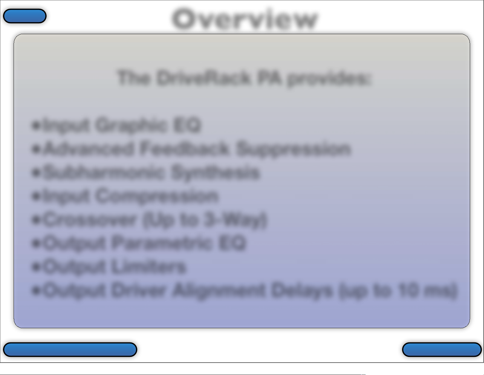
The DriveRack PA provides:
•
Input Graphic EQ
•
Advanced Feedback Suppression
•
Subharmonic Synthesis
•
Input Compression
•
Crossover (Up to 3-Way)
•
Output Parametric EQ
•
Output Limiters
•
Output Driver Alignment Delays (up to 10 ms)
Overview
ProceedBack To Main Menu
Index
3
Page 4
Overview
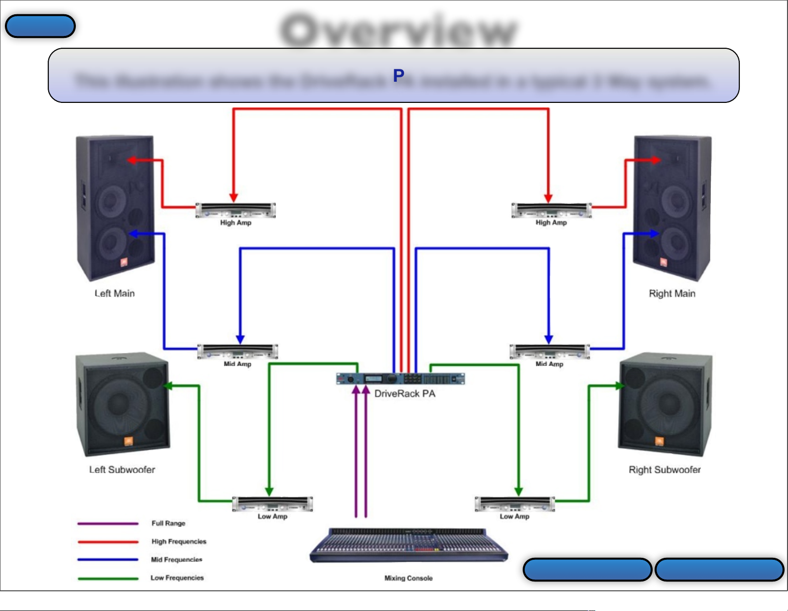
This illustration shows the DriveRack PA installed in a typical 3 Way system.
ProceedPrev Slide
Index
4
Page 5
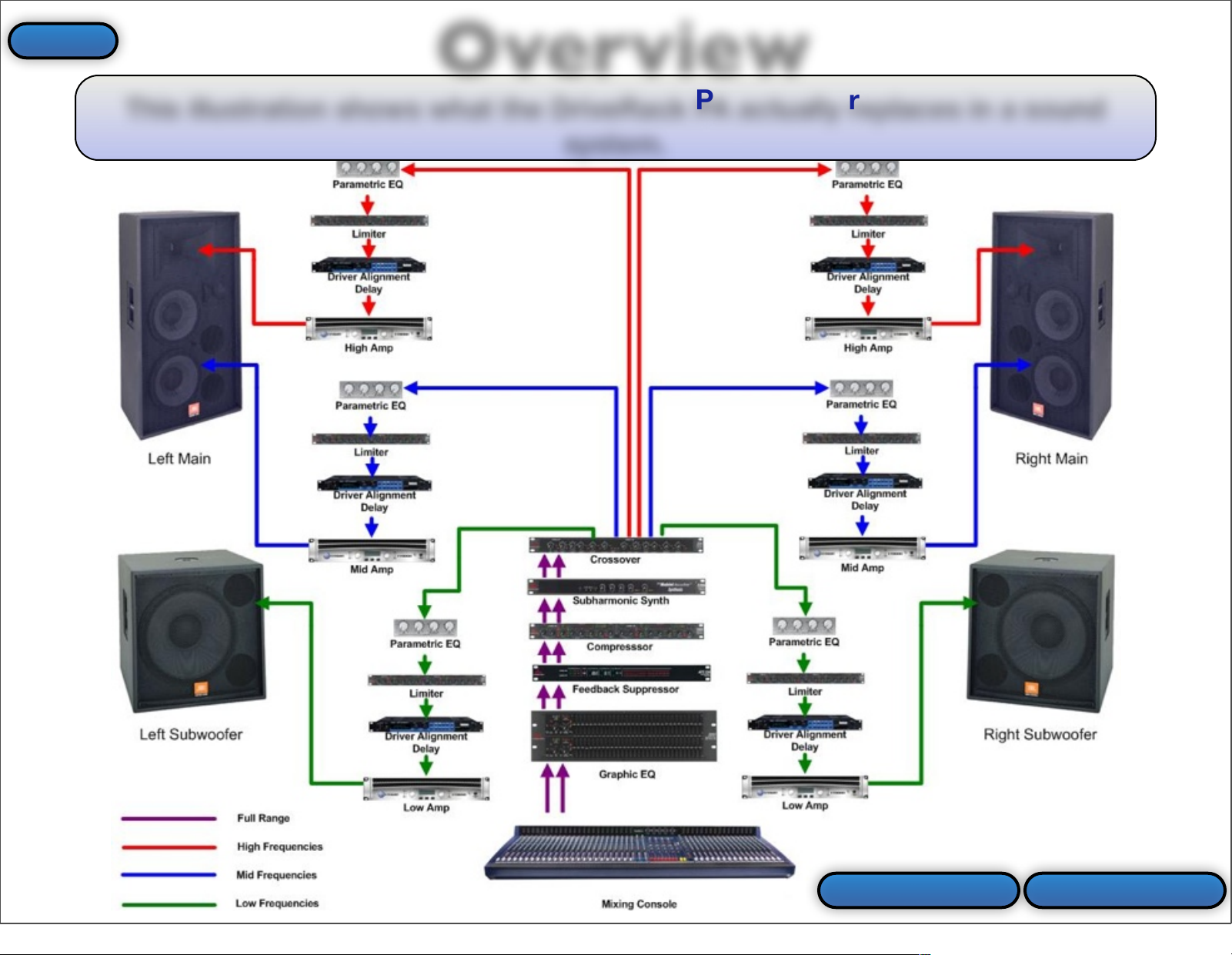
This illustration shows what the DriveRack PA actually replaces in a sound
system.
Overview
ProceedPrev Slide
Index
5
Page 6
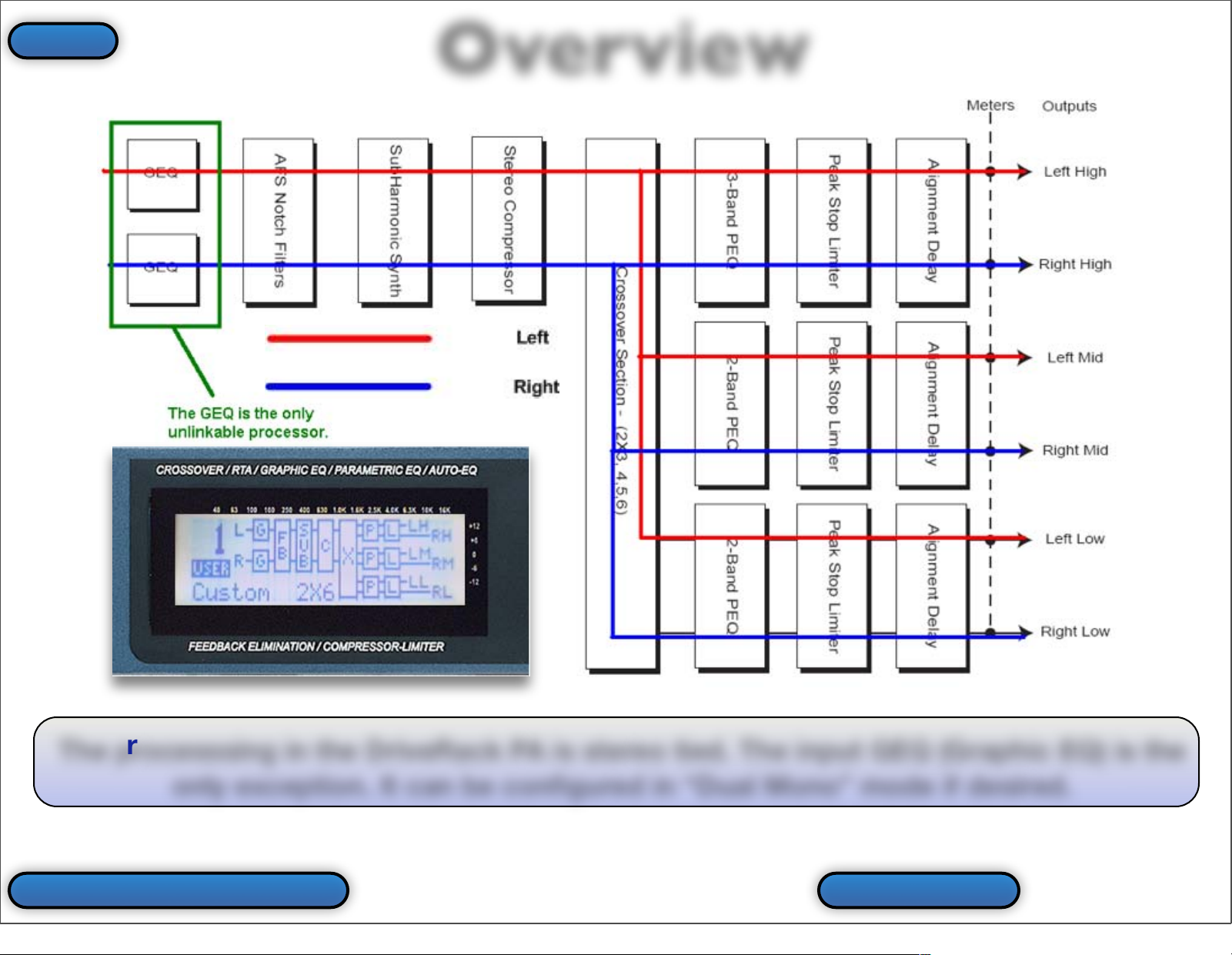
The processsing in the DriveRack PA is stereo tied. The input GEQ (Graphic EQ) is the
only exception. It can be configured in “Dual Mono” mode if desired.
Overview
Back To Main Menu Prev Slide
Index
6
Page 7
Don’t be afraid to experiment with the buttons and
controls on the DriveRack PA. It is recommended
that you familiarize yourself with these controls
before connecting the device to your system. Once
you feel comfortable with the navigation of the unit
you can easily perform the Factory Hard Reset
procedure (as described in the back of the Owner’s
Manual). This Hard Reset will set the device back to
it’s factory default state.
Enjoy!
The dbx Team
Basic Navigation
ProceedBack To Main Menu
Index
7
Page 8
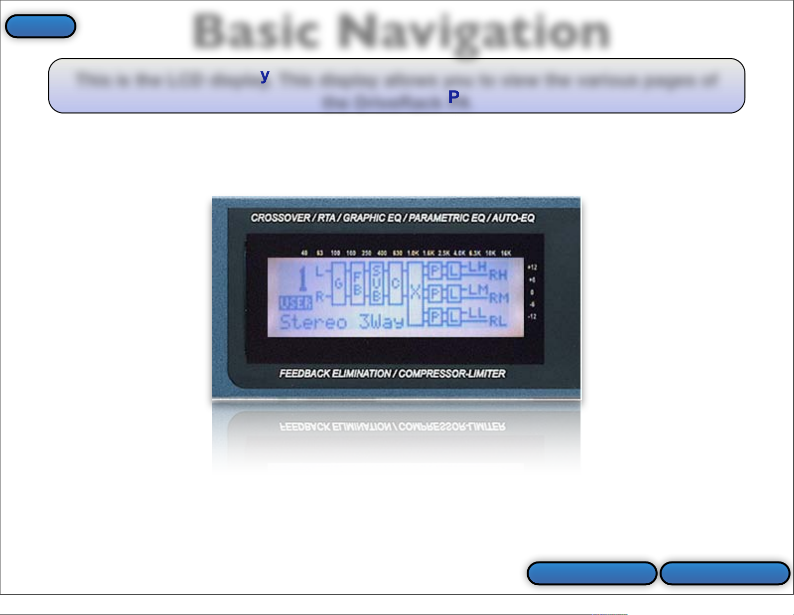
This is the LCD display. This display allows you to view the various pages of
the DriveRack PA
Basic Navigation
ProceedPrev Slide
Index
8
Page 9
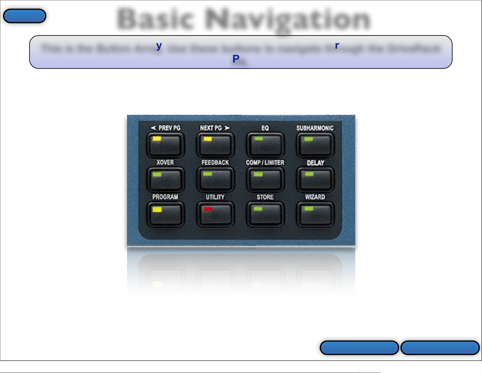
This is the Button Array. Use these buttons to navigate through the DriveRack
PA.
Basic Navigation
ProceedPrev Slide
Index
9
Page 10
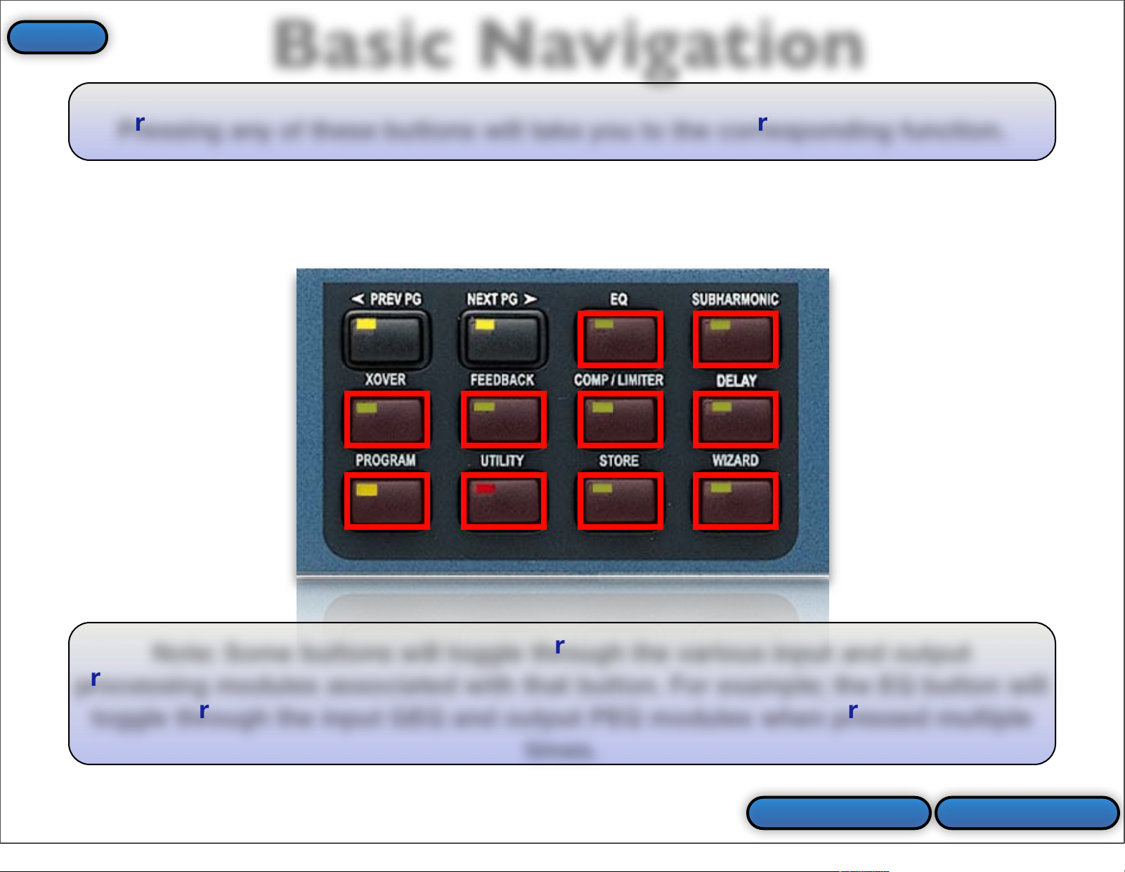
Pressing any of these buttons will take you to the corresponding function.
Basic Navigation
Note: Some buttons will toggle through the various input and output
processing modules associated with that button. For example; the EQ button will
toggle through the input GEQ and output PEQ modules when pressed multiple
times.
ProceedPrev Slide
Index
10
Page 11
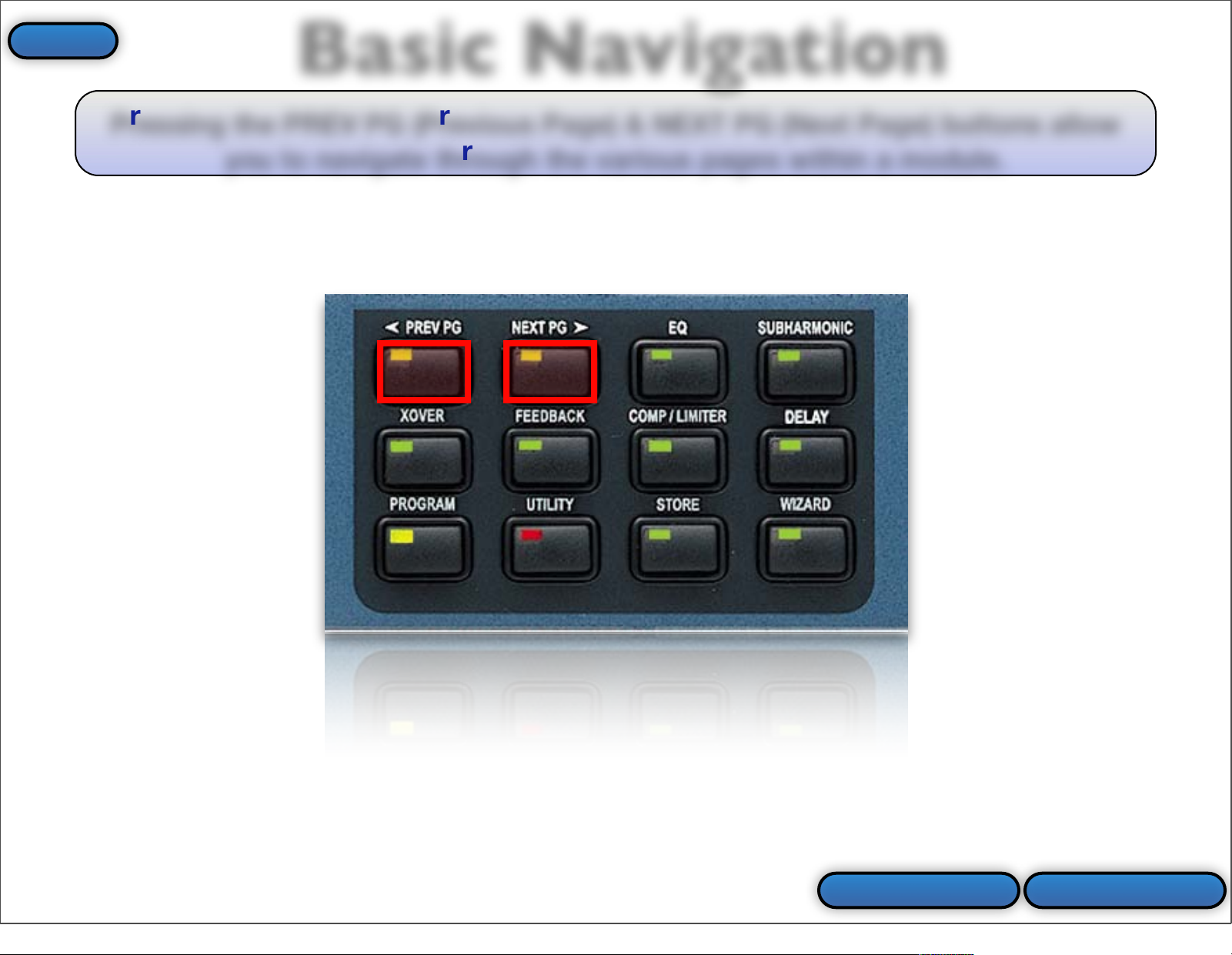
Pressing the PREV PG (Previous Page) & NEXT PG (Next Page) buttons allow
you to navigate through the various pages within a module.
Basic Navigation
ProceedPrev Slide
Index
11
Page 12

The DATA ENCODER is your “SELECT” button when pressed in.
Basic Navigation
ProceedPrev Slide
Index
12
Page 13
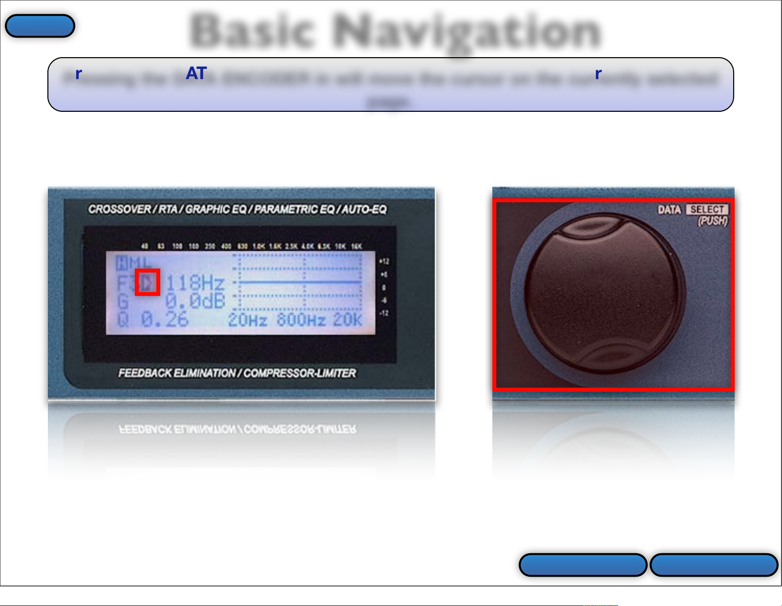
Pressing the DATA ENCODER in will move the cursor on the currently selected
page.
Basic Navigation
ProceedPrev Slide
Index
13
Page 14
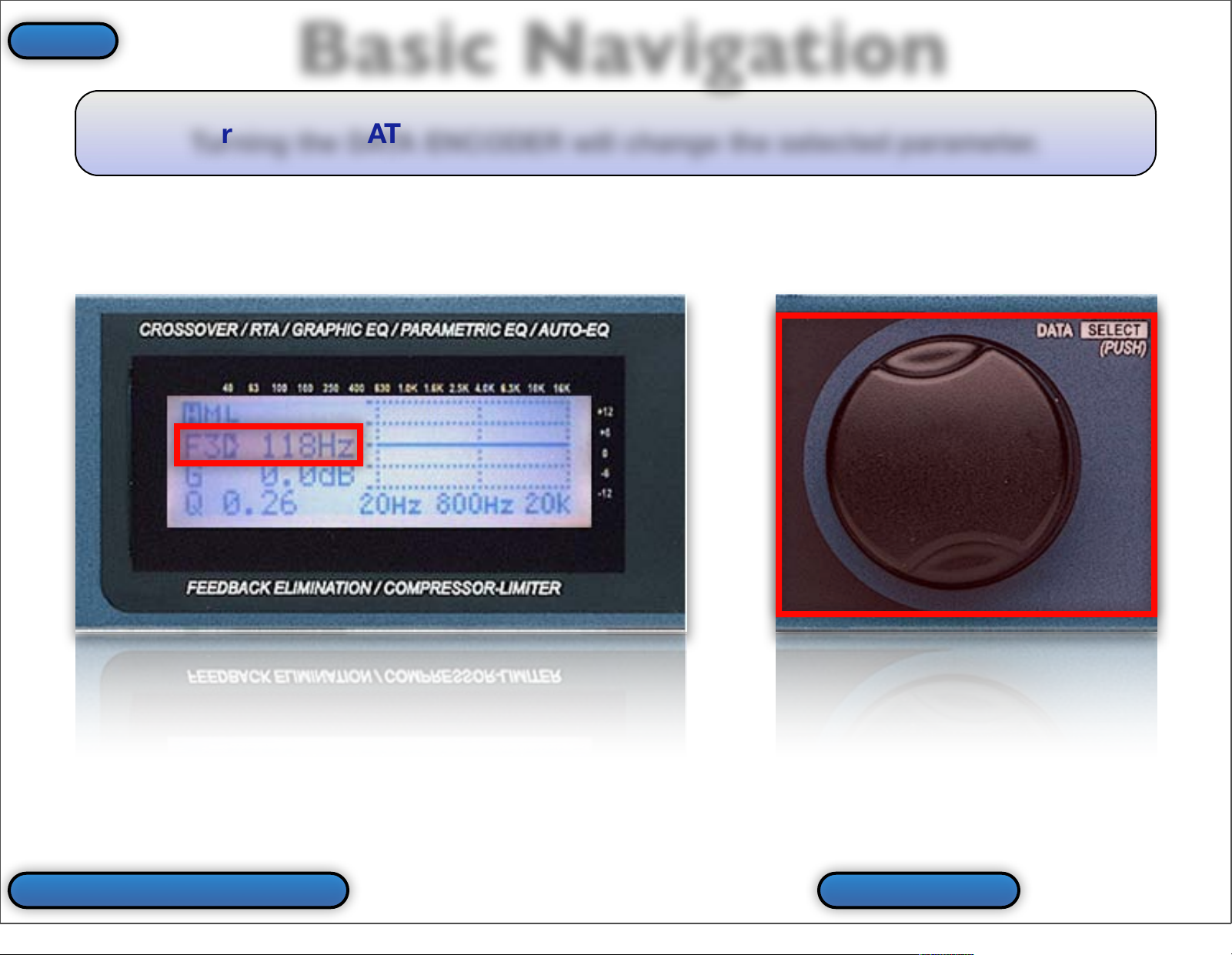
Turning the DATA ENCODER will change the selected parameter.
Basic Navigation
Back To Main Menu Prev Slide
Index
14
Page 15
Virtual DriveRack PA
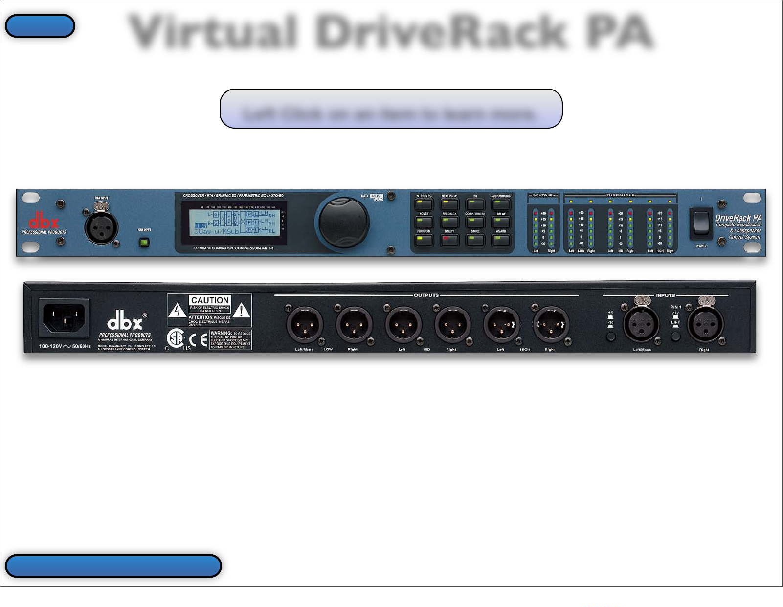
Left Click on an item to learn more.
Back To Main Menu
Index
15
Page 16
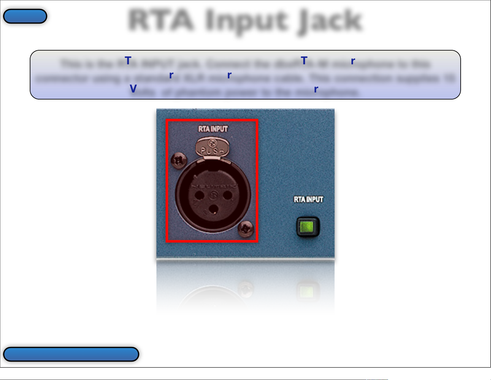
This is the RTA INPUT jack. Connect the dbxRTA-M microphone to this
connector using a standard XLR microphone cable. This connection supplies 15
Volts of phantom power to the microphone.
RTA Input Jack
Back To Virtual PA
Index
16
Page 17
RTA Input Button
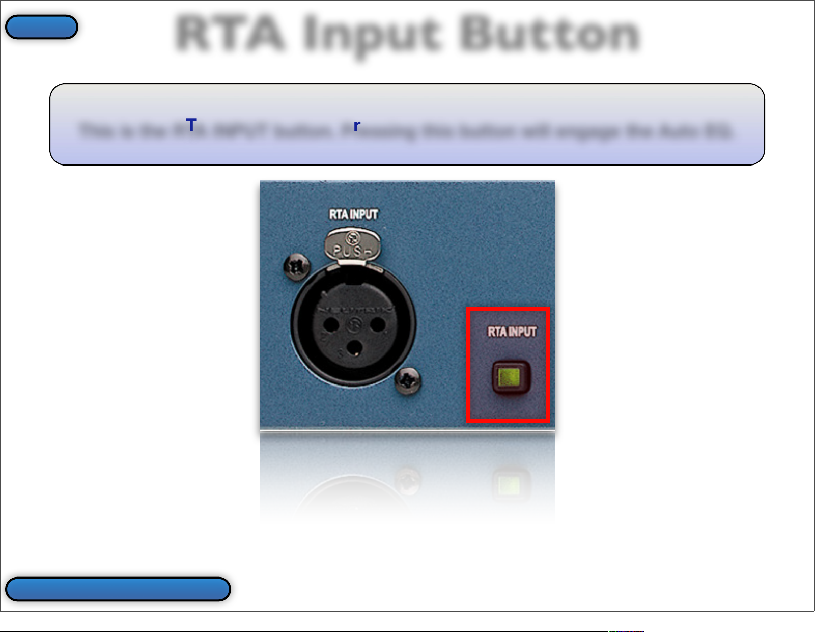
This is the RTA INPUT button. Pressing this button will engage the Auto EQ.
Back To Virtual PA
Index
17
Page 18
LCD/Button Array
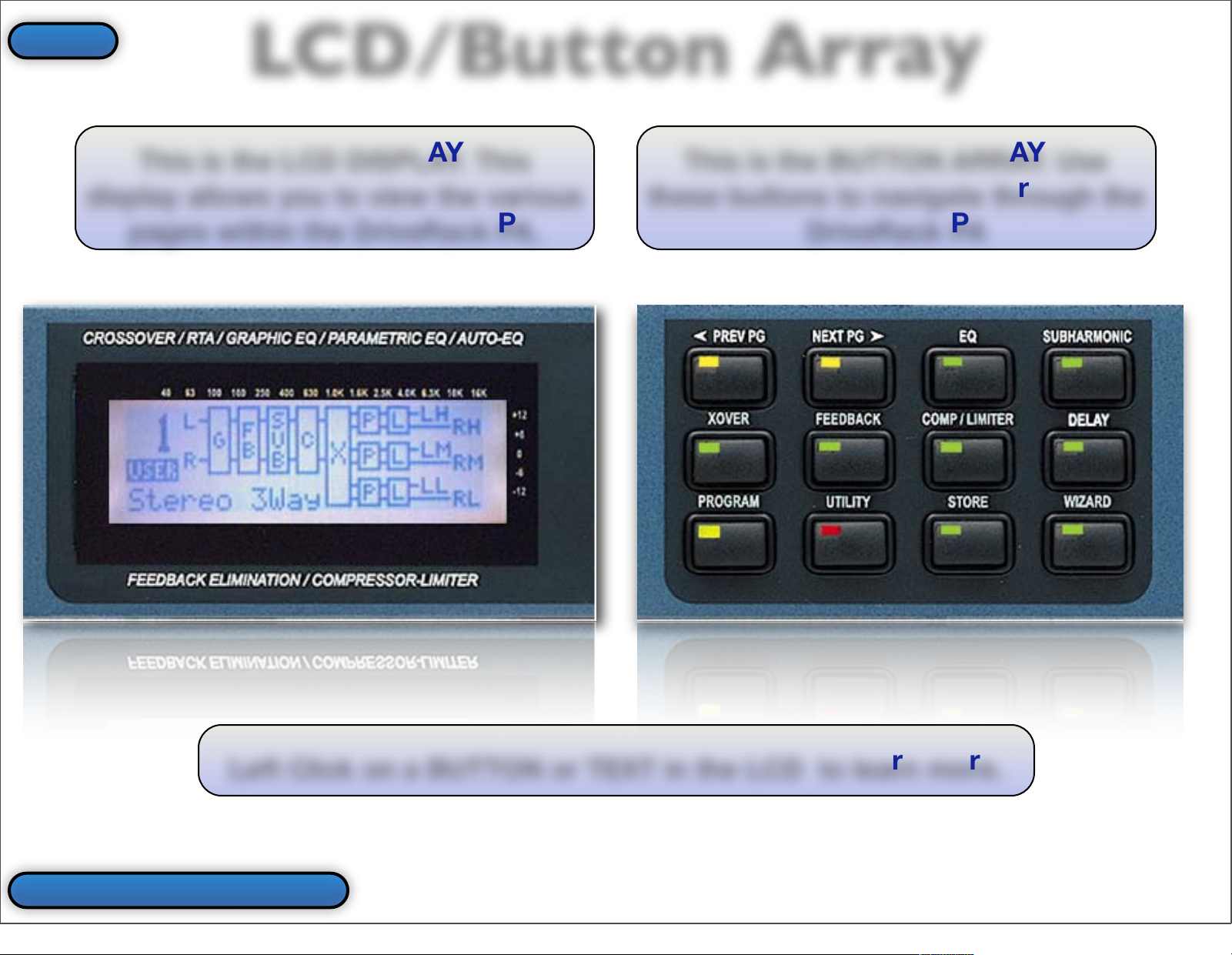
This is the LCD DISPLAY. This
display allows you to view the various
pages within the DriveRack PA.
This is the BUTTON ARRAY. Use
these buttons to navigate through the
DriveRack PA
Left Click on a BUTTON or TEXT in the LCD to learn more.
Back To Virtual PA
Index
18
Page 19
Preset #
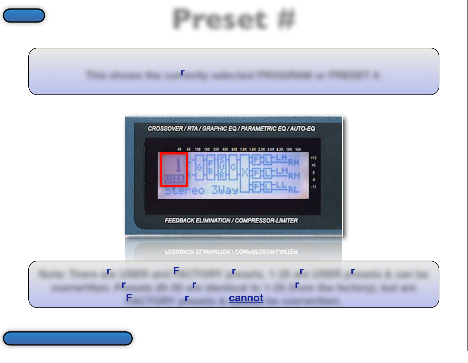
This shows the currently selected PROGRAM or PRESET #.
Note: There are USER and FACTORY presets. 1-25 are USER presets & can be
overwritten. Presets 26-50 are identical to 1-25 (from the factory), but are
FACTORY presets &
cannot
be overwritten.
Back To Virtual PA
Index
19
Page 20
Preset Name
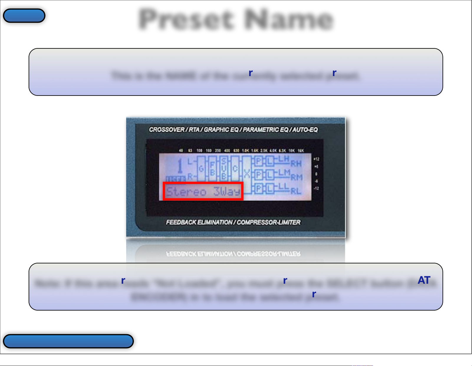
This is the NAME of the currently selected preset.
Note: If this area reads “Not Loaded”, you must press the SELECT button (DATA
ENCODER) in to load the selected preset.
Back To Virtual PA
Index
20
Page 21
Input Configuration
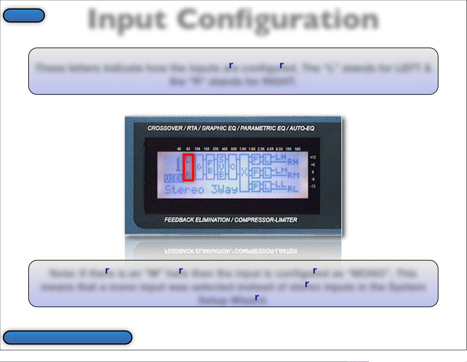
These letters indicate how the inputs are configured. The “L” stands for LEFT &
the “R” stands for RIGHT.
Note: If there is an “M” here then the input is configured as “MONO”. This
means that a mono input was selected instead of stereo inputs in the System
Setup Wizard.
Back To Virtual PA
Index
21
Page 22
GEQ/PEQ
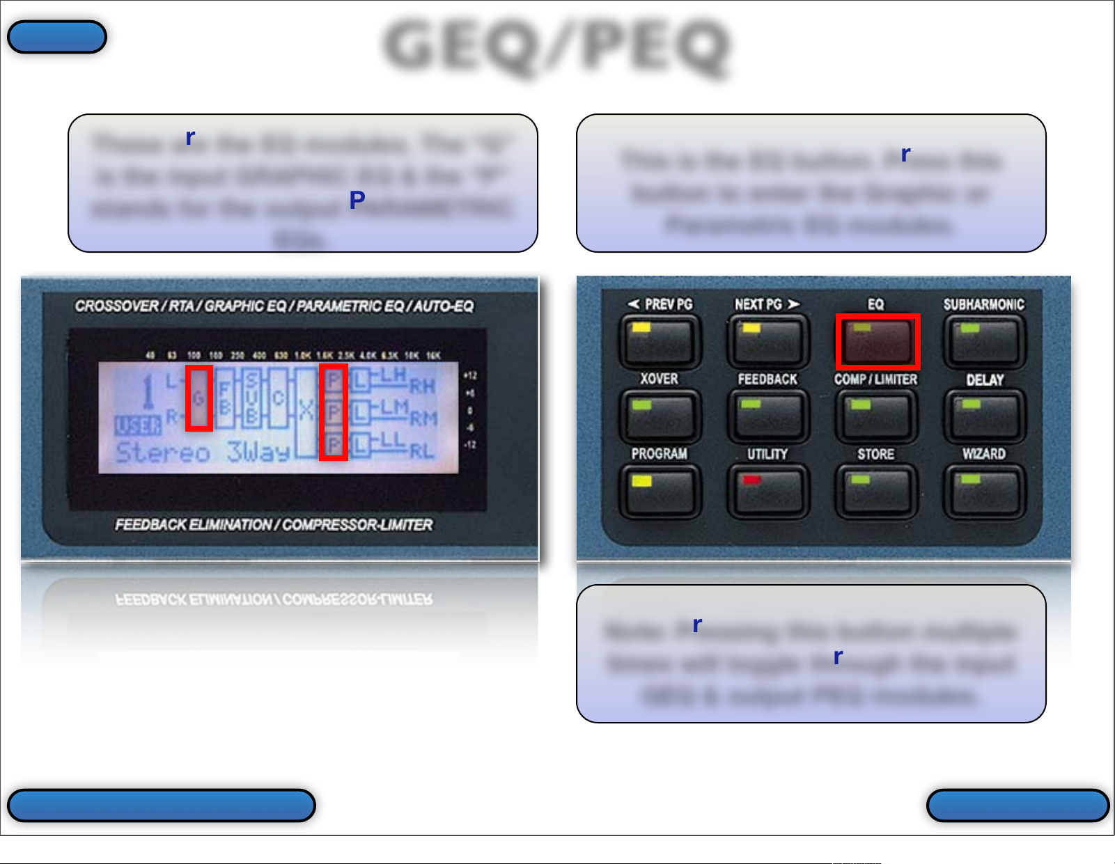
These are the EQ modules. The “G”
is the input GRAPHIC EQ & the “P”
stands for the output PARAMETRIC
EQs.
This is the EQ button. Press this
button to enter the Graphic or
Parametric EQ modules.
Note: Pressing this button multiple
times will toggle through the input
GEQ & output PEQ modules.
More InfoBack To Buttons
Index
22
Page 23
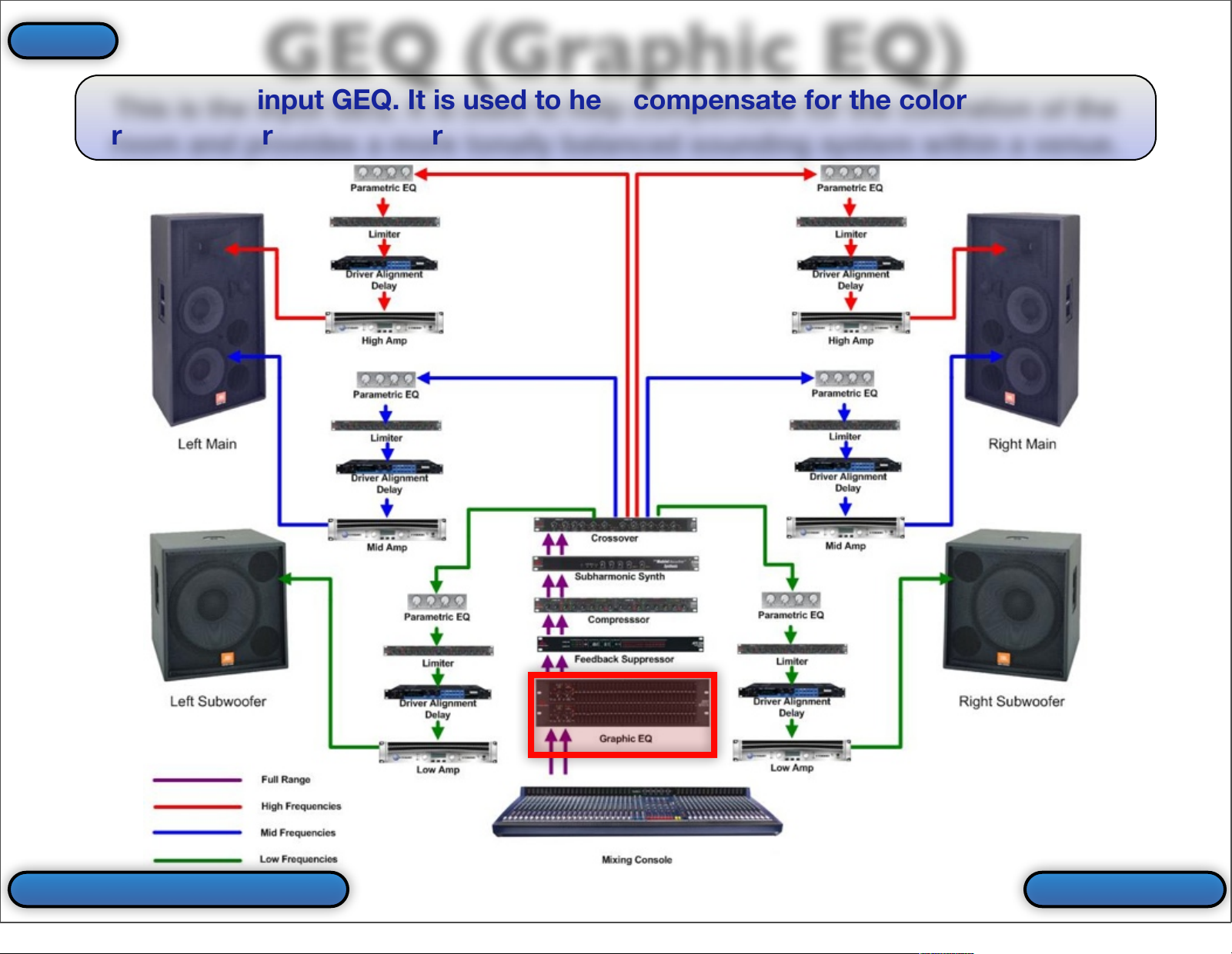
This is the input GEQ. It is used to help compensate for the coloration of the
room and provides a more tonally balanced sounding system within a venue.
GEQ (Graphic EQ)
Back To EQ More Info
Index
23
Page 24
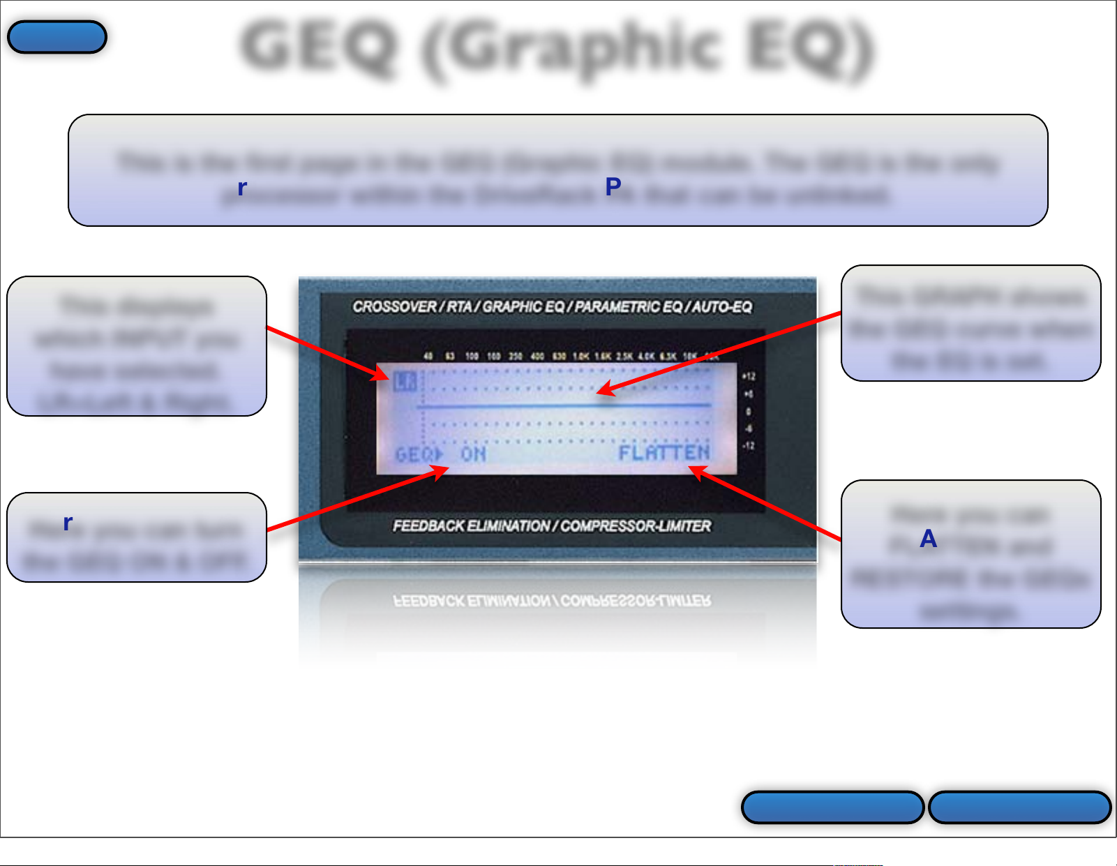
This is the first page in the GEQ (Graphic EQ) module. The GEQ is the only
processor within the DriveRack PA that can be unlinked.
This displays
which INPUT you
have selected.
LR=Left & Right.
Here you can turn
the GEQ ON & OFF.
This GRAPH shows
the GEQ curve when
the EQ is set.
Here you can
FLATTEN and
RESTORE the GEQs
settings.
Next Page
GEQ (Graphic EQ)
Prev Slide
Index
24
Page 25
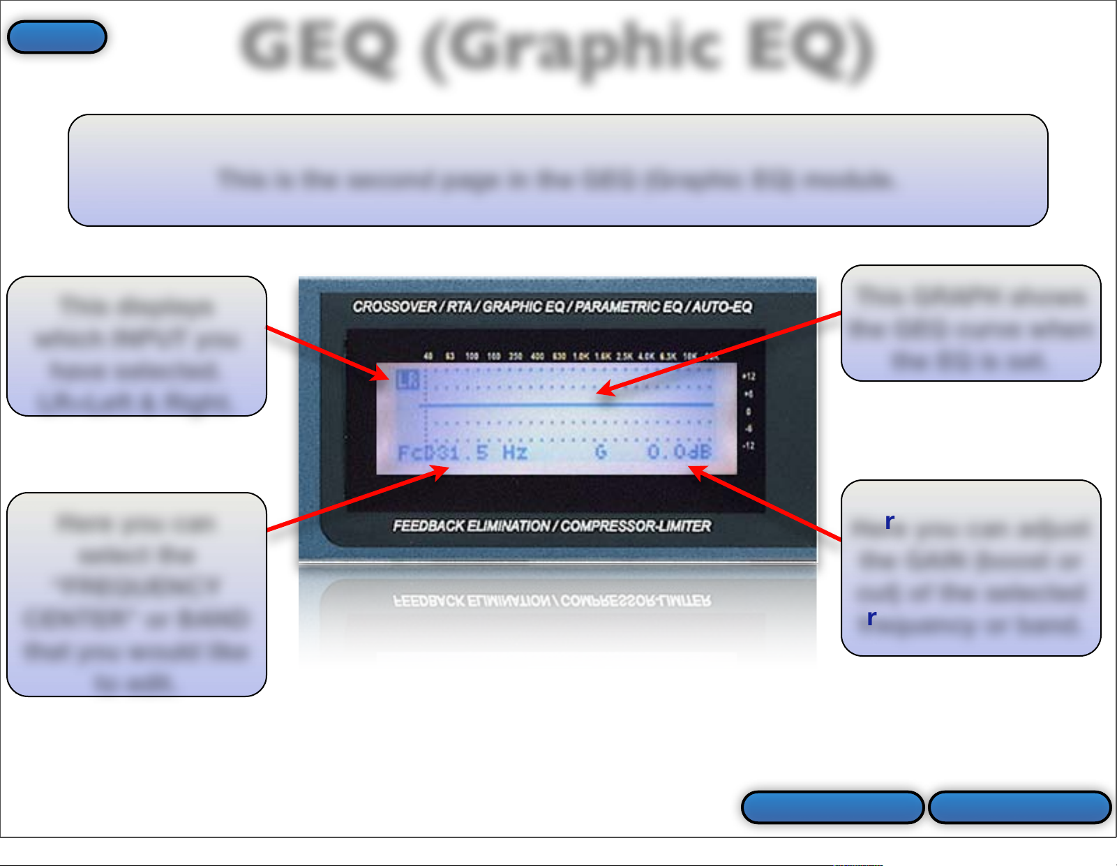
This is the second page in the GEQ (Graphic EQ) module.
Here you can
select the
“FREQUENCY
CENTER” or BAND
that you would like
to edit.
This GRAPH shows
the GEQ curve when
the EQ is set.
Here you can adjust
the GAIN (boost or
cut) of the selected
frequency or band.
Prev Slide Next Page
This displays
which INPUT you
have selected.
LR=Left & Right.
GEQ (Graphic EQ)
Index
25
Page 26
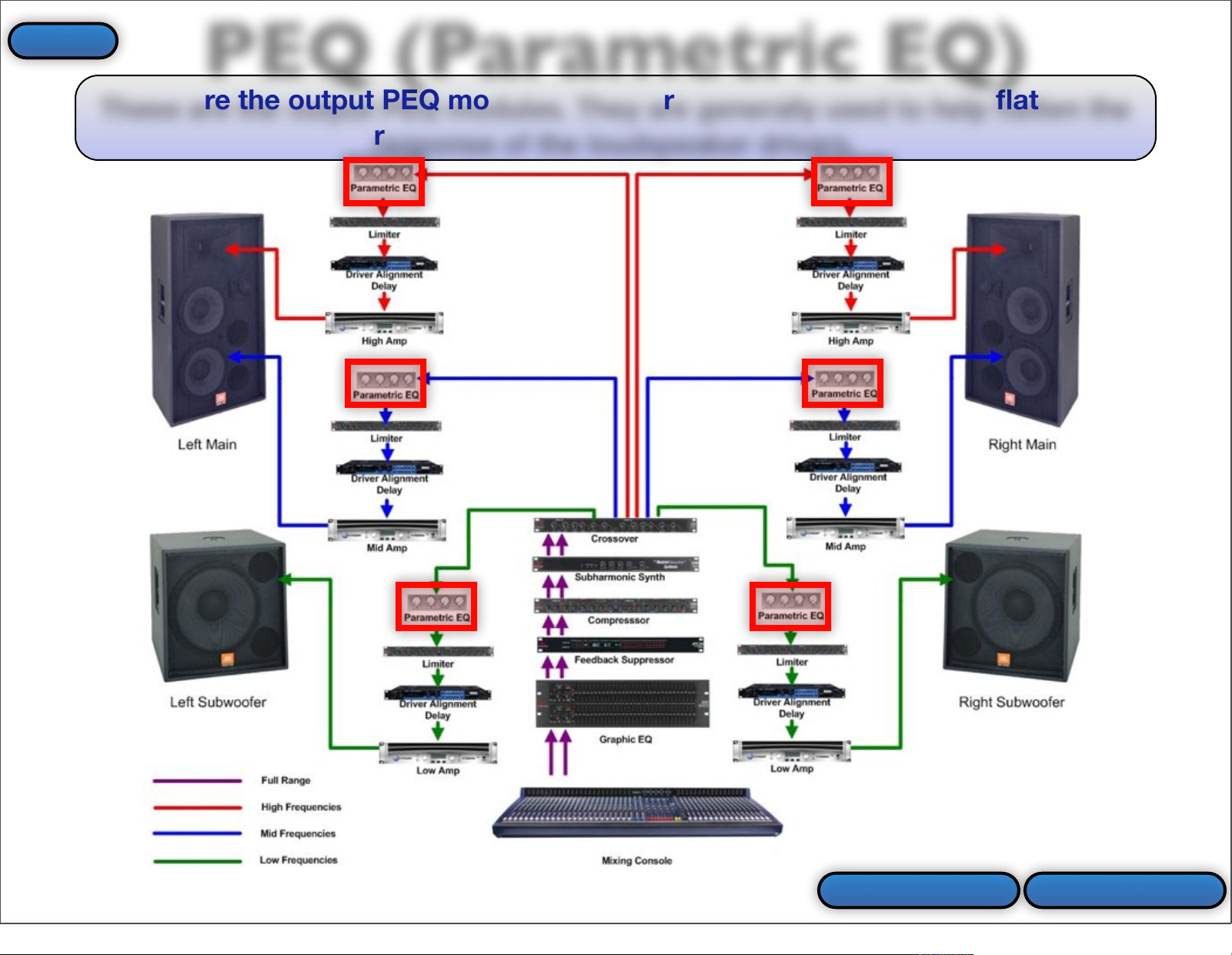
These are the output PEQ modules. They are generally used to help flatten the
response of the loudspeaker drivers.
PEQ (Parametric EQ)
Prev Slide More Info
Index
26
Page 27

This is the first page in the PEQ (Parametric EQ) module.
This displays which
OUTPUT you have
selected.
Here you can turn
the PEQ ON & OFF.
This GRAPH shows
the PEQ curve when
the EQ is set.
Here you can
FLATTEN and
RESTORE the GEQs
settings.
Here you can select which
types of filters will be available
(LOW SHELF, HIGH SHELF,
BOTH or all BELL).
Prev Slide Next Page
PEQ (Parametric EQ)
Index
27
Page 28

This displays which
OUTPUT you have
selected.
This displays which
BAND is selected.
This is
“FREQUENCY 1”.
This GRAPH shows
the PEQ curve when
the EQ is set.
Here you can
change the GAIN
(boost or cut) of
band 1.
This is the second page in the PEQ (Parametric EQ) module.
Here you can adjust the “SLOPE” or
“Q” of the filter depending upon what
you selected on the first page.
“S”= Slope “Q”=Width
Prev Slide Next Page
PEQ (Parametric EQ)
Index
28
Page 29

This displays which
OUTPUT you have
selected.
This displays which
BAND is selected.
This is
“FREQUENCY 2”.
This GRAPH shows
the PEQ curve when
the EQ is set.
Here you can
change the GAIN
(boost or cut) of
band 2.
Here you can adjust the
“Q” of the filter.
“Q”=Width
This is the third page in the PEQ (Parametric EQ) module.
Prev Slide Next Page
PEQ (Parametric EQ)
Index
29
Page 30

This displays which
OUTPUT you have
selected.
This displays which
BAND is selected.
This is
“FREQUENCY 3”.
This GRAPH shows
the PEQ curve when
the EQ is set.
Here you can
change the GAIN
(boost or cut) of
band 3.
This is the fourth page in the PEQ (Parametric EQ) module.
Note: You will only
see this page when
editing the “High
Outputs”. This is
because the “ Mid”
& “Low” Output
PEQs have only 2
bands (“F1” & “F2”).
Back To EQ
Here you can adjust the “SLOPE” or
“Q” of the filter depending upon what
you selected on the first page.
“S”= Slope “Q”=Width
Prev Slide
PEQ (Parametric EQ)
Index
30
Page 31

Feedback (AFS)
This is the FEEDBACK or AFS module.
This is the FEEDBACK button. Press
this button to enter the AFS
(Advanced Feedback Suppression)
module.
More InfoBack To Buttons
Index
31
Page 32

This is the input AFS module. It is used to help control feedback in the system.
Feedback (AFS)
Back To AFS More Info
Index
32
Page 33

Here you can
CLEAR all filters or
just the Live filters.
Here you can turn
the AFS ON & OFF.
This is the first page in the FEEDBACK or AFS module.
This shows you how many FIXED VS
LIVE filters are allocated. It also
shows you how many filters are set.
Next Page
Feedback (AFS)
Prev Slide
Index
33
Page 34

Here you can select
whether AFS is in
LIVE or FIXED mode.
This shows you how many FIXED VS
LIVE filters are allocated. It also
shows you how many filters are set.
This is the second page in the FEEDBACK or AFS module.
Here you can select
how wide or narrow
the notch filters will
be.
Speech=Wide
Music High=Narrow
Here you can select
how many filters are
ALLOCATED as Fixed.
Prev Slide Next Page
Feedback (AFS)
Index
34
Page 35

Here you can turn the
Live Filter Lift ON &
OFF.
This shows you how many FIXED VS
LIVE filters are allocated. It also
shows you how many filters are set.
This is the third page in the FEEDBACK or AFS module.
Here you can set
HOW LONG the Live
Filters will remain set
before they are lifted.
Back To AFS Prev Slide
Feedback (AFS)
Index
35
Page 36
Subharmonic Synth
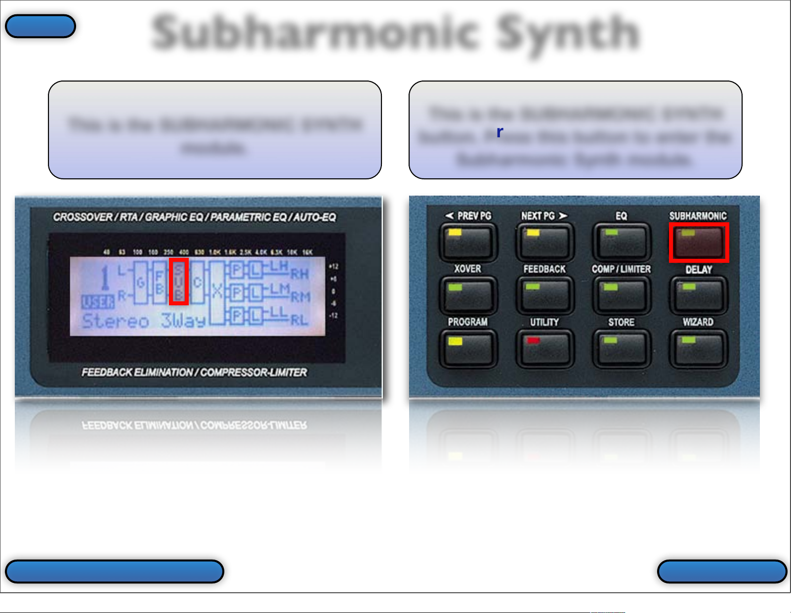
This is the SUBHARMONIC SYNTH
module.
This is the SUBHARMONIC SYNTH
button. Press this button to enter the
Subharmonic Synth module.
More InfoBack To Buttons
Index
36
Page 37
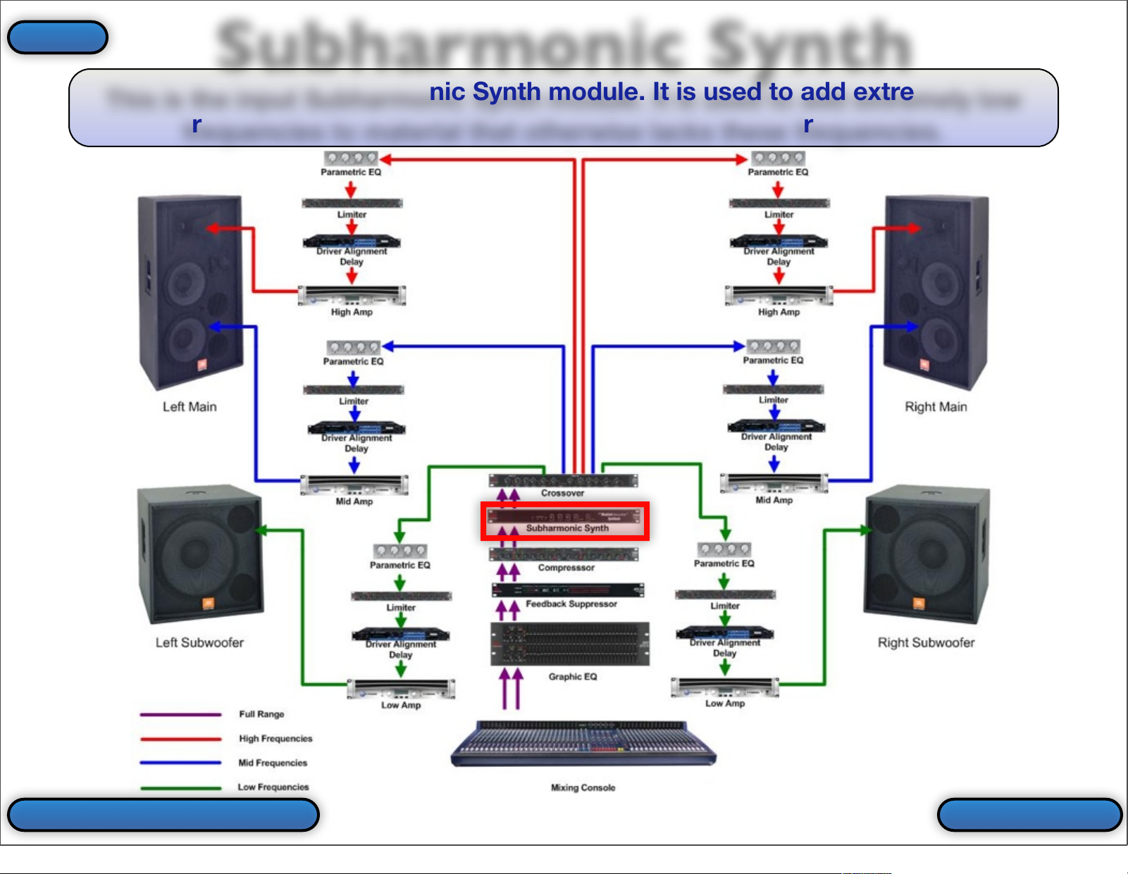
This is the input Subharmonic Synth module. It is used to add extremely low
frequencies to material that otherwise lacks these frequencies.
Subharmonic Synth
Back To Sub Synth More Info
Index
37
Page 38

This is the first page in the SUBHARMONIC SYNTH module.
Here you can turn the
Subharmonic Synth
ON & OFF.
Here you can set the
MASTER LEVEL of the
Subharmonic Synth
process.
Next Page
Subharmonic Synth
Prev Slide
Index
38
Page 39

This is the second page in the SUBHARMONIC SYNTH module.
Here you can set the
LEVEL of the first
range of frequencies.
Here you can set the
LEVEL of the second
range of frequencies.
Back To Sub Synth Prev Slide
Subharmonic Synth
Index
39
Page 40

Compressor/Limiter
These are the Dynamics
(COMPRESSOR & LIMITER) modules.
This is the COMP/LIMITER button.
Press this button to enter the input
COMPRESSOR or output LIMITER
modules.
Note: Pressing this button multiple
times will toggle through the input
Compressor & output Limiter
modules.
More InfoBack To Buttons
Index
40
Page 41

This is the input Compressor module. It is used to lower the dynamic range of
the system. In other words, it brings louder signals down and softer signals up.
Back To Comp/Lim
Compressor
More Info
Index
41
Page 42

This is the first page in the input COMPRESSOR module.
This is your GAIN
REDUCTION METER.
It shows how many
dB of compression is
taking place.
Here you can turn
the Compressor ON &
OFF.
This is your
THRESHOLD
INDICATOR.
“-”=Below Threshold
“O”=In the Overeasy Range
“+”=Over the Threshold
This illustrates that
you are editing the
input “Left & Right”
“Compressor” module.
Here you can turn
OVEREASY mode ON
& OFF. This is a
variable knee (VariKnee) ranging from
1-10.
Next Page
Compressor
Prev Slide
Index
42
Page 43

This is the second page in the COMPRESSOR module.
This is your GAIN
REDUCTION METER.
It shows how many
dB of compression is
taking place.
Here you can set
the THRESHOLD or at
what level the
Compressor will be
engaged.
This is your
THRESHOLD
INDICATOR.
“-”=Below Threshold
“O”=In the Overeasy Range
“+”=Over the Threshold
This illustrates that
you are editing the
input “Left & Right”
“Compressor” module.
Here you can adjust
the OUTPUT or
MAKE-UP gain of the
Compressor.
Here you can set the RATIO. The
RATIO determines how much
compression will take place once the
Threshold is exceeded.
Prev Slide Next Page
Compressor
Index
43
Page 44
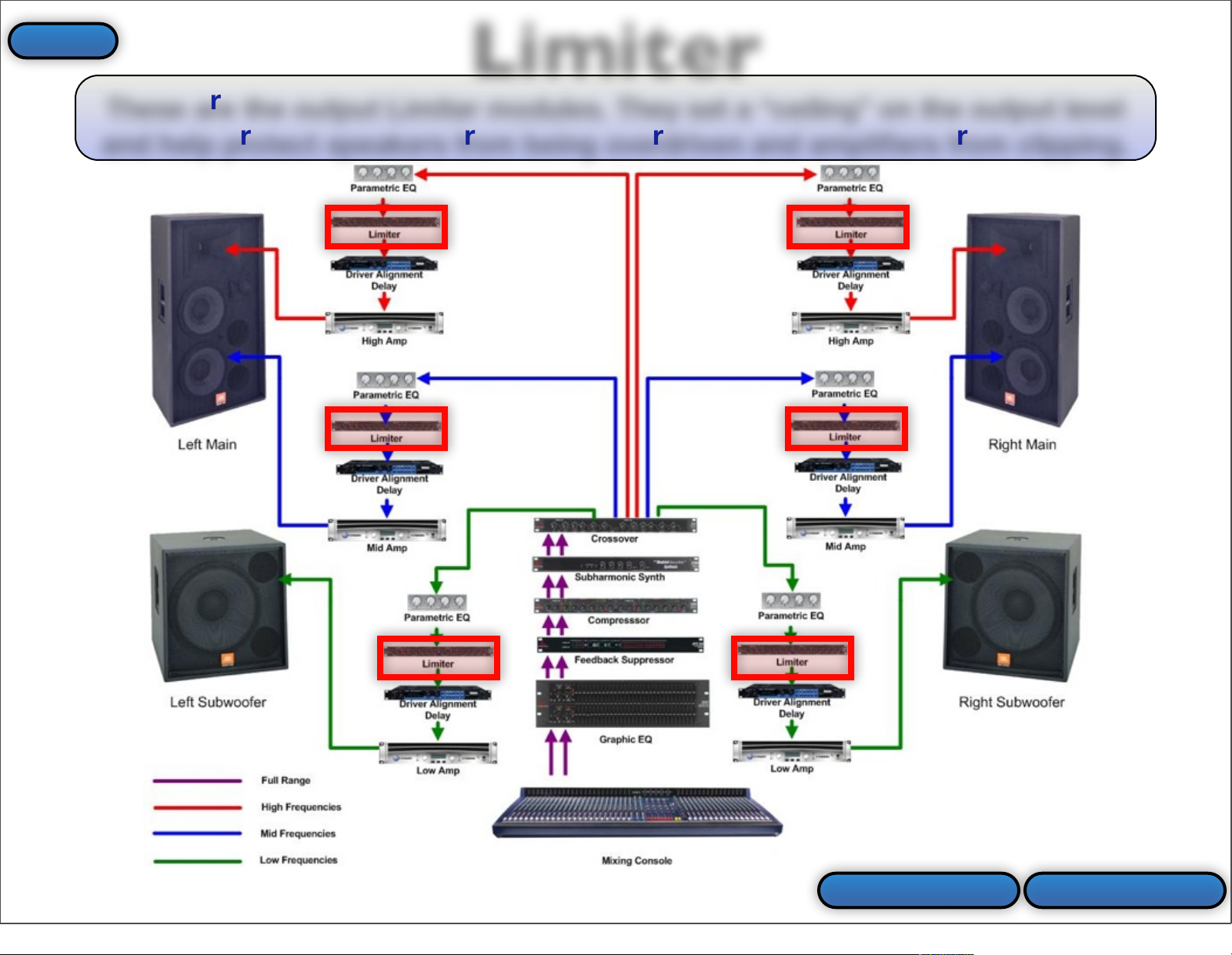
These are the output Limiter modules. They set a “ceiling” on the output level
and help protect speakers from being overdriven and amplifiers from clipping.
Limiter
Prev Slide More Info
Index
44
Page 45
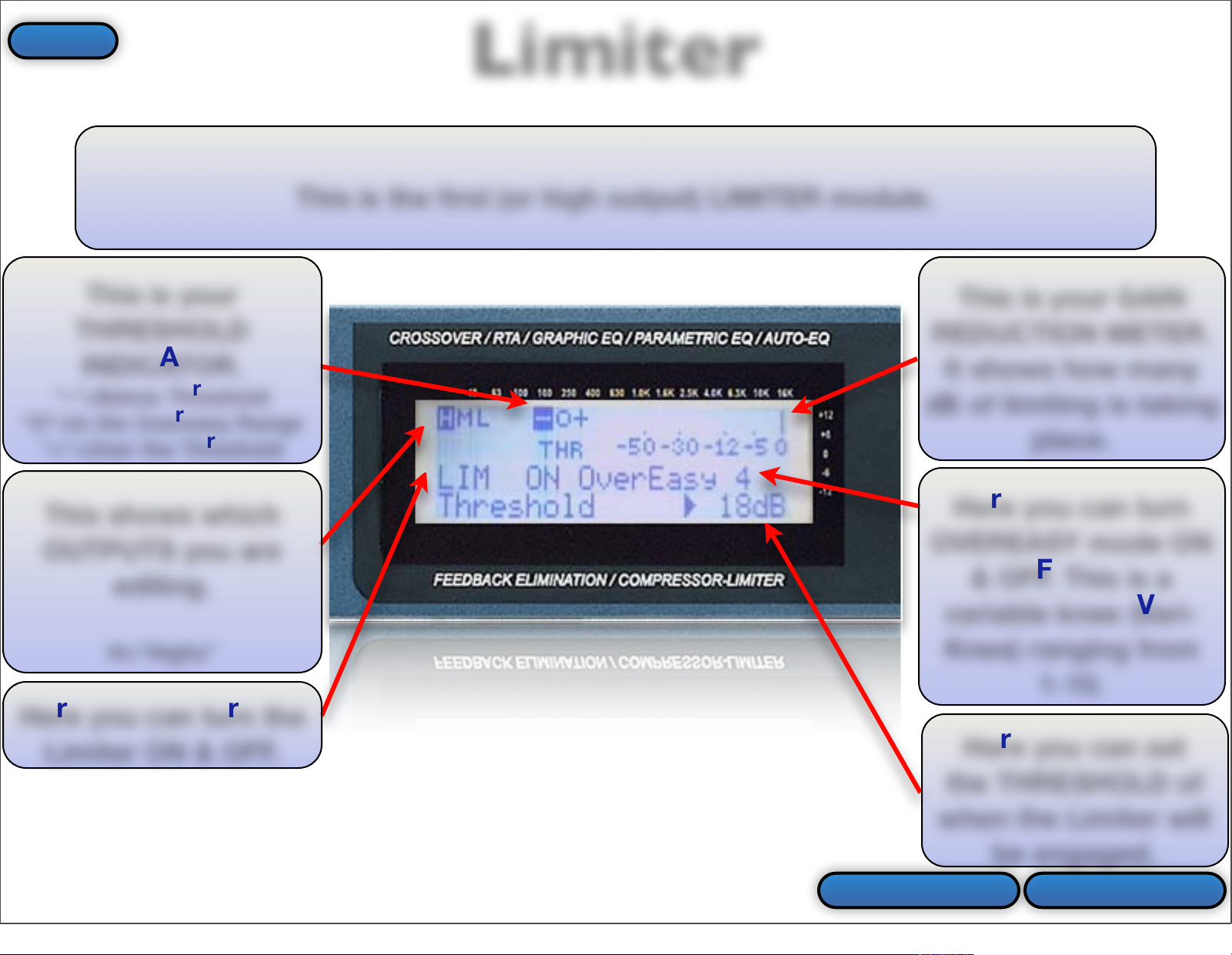
This is the first (or high output) LIMITER module.
This is your GAIN
REDUCTION METER.
It shows how many
dB of limiting is taking
place.
This is your
THRESHOLD
INDICATOR.
“-”=Below Threshold
“O”=In the Overeasy Range
“+”=Over the Threshold
This shows which
OUTPUTS you are
editing.
H=”Highs”
Here you can turn the
Limiter ON & OFF.
Here you can set
the THRESHOLD of
when the Limiter will
be engaged.
Here you can turn
OVEREASY mode ON
& OFF. This is a
variable knee (VariKnee) ranging from
1-10.
Prev Slide Next Page
Limiter
Index
45
Page 46

This is the second (or mid output) LIMITER module. This page will only be shown
in a 3 Way system.
This is your GAIN
REDUCTION METER.
It shows how many
dB of limiting is taking
place.
This is your
THRESHOLD
INDICATOR.
“-”=Below Threshold
“O”=In the Overeasy Range
“+”=Over the Threshold
This shows which
OUTPUTS you are
editing.
M=”Mids”
Here you can turn the
Limiter ON & OFF.
Here you can set
the THRESHOLD of
when the Limiter will
be engaged.
Here you can turn
OVEREASY mode ON
& OFF. This is a
variable knee (VariKnee) ranging from
1-10.
Prev Slide Next Page
Limiter
Index
46
Page 47

This is your GAIN
REDUCTION METER.
It shows how many
dB of limiting is taking
place.
This is your
THRESHOLD
INDICATOR.
“-”=Below Threshold
“O”=In the Overeasy Range
“+”=Over the Threshold
Here you can turn the
Limiter ON & OFF.
Here you can set
the THRESHOLD of
when the Limiter will
be engaged.
Here you can turn
OVEREASY mode ON
& OFF. This is a
variable knee (VariKnee) ranging from
1-10.
Back To Comp/Lim Prev Slide
This shows which
OUTPUTS you are
editing.
L=”Lows”
This is the third (or low output) LIMITER module. This page will only be shown in
a 2 Way or 3 Way system.
Limiter
Index
47
Page 48

Xover (Crossover)
This is the XOVER (Crossover)
module.
This is the XOVER button. Press this
button to enter the Crossover module.
More InfoBack To Buttons
Index
48
Page 49

This is the Xover module. It is used to send the proper range of frequencies to
each loudspeaker driver.
Back To X-Over More Info
Xover (Crossover)
Index
49
Page 50

This is the first page in the XOVER module. This page is for editing the HIGH
PASS filter on the “Low Outputs”. The low outputs will only be available in a 2-
Way or 3-Way configuration.
This GRAPH shows
you how the
crossover points are
set a at a glance.
This shows which
OUTPUTS you are
editing.
L=”Lows”
This is the crossover
point which is edited
on this page.
This is the OUTPUT
GAIN for the low
outputs.
This is the crossover
FREQUENCY for the
high pass on the low
outputs.
This is the filter
type and slope
selected for the high
pass filter for the low
outputs.
Next PagePrev Slide
Xover (Crossover)
Index
50
Page 51

This is the second page in the XOVER module. This page is for editing the LOW
PASS filter on the “Low Outputs”. The low outputs will only be available in a 2-
Way or 3-Way configuration.
This GRAPH shows
you how the
crossover points are
set a at a glance.
This shows which
OUTPUTS you are
editing.
L=”Lows”
This is the crossover
point which is edited
on this page.
This is the crossover
FREQUENCY for the
low pass on the low
outputs.
This is the filter
type and slope
selected for the low
pass filter for the low
outputs.
Prev Slide Next Page
Xover (Crossover)
Index
51
Page 52

This is the third page in the XOVER module. This page is for editing the HIGH
PASS filter on the “Mid Outputs”. The mid outputs will only be available in a 3-
Way configuration.
This GRAPH shows
you how the
crossover points are
set a at a glance.
This shows which
OUTPUTS you are
editing.
M=”Mids”
This is the crossover
point which is edited
on this page.
This is the OUTPUT
GAIN for the mid
outputs.
This is the crossover
FREQUENCY for the
high pass on the mid
outputs.
This is the filter
type and slope
selected for the high
pass filter for the mid
outputs.
Prev Slide Next Page
Xover (Crossover)
Index
52
Page 53

This is the fourth page in the XOVER module. This page is for editing the LOW
PASS filter on the “Mid Outputs”. The mid outputs will only be available in a 3-
Way configuration.
This GRAPH shows
you how the
crossover points are
set a at a glance.
This is the crossover
point which is edited
on this page.
This is the crossover
FREQUENCY for the
low pass on the mid
outputs.
This is the filter
type and slope
selected for the low
pass filter for the mid
outputs.
This shows which
OUTPUTS you are
editing.
M=”Mids”
Prev Slide Next Page
Xover (Crossover)
Index
53
Page 54

This is the fifth page in the XOVER module. This page is for editing the HIGH
PASS filter on the “High Outputs”.
This GRAPH shows
you how the
crossover points are
set a at a glance.
This shows which
OUTPUTS you are
editing.
H=”Highs”
This is the crossover
point which is edited
on this page.
This is the OUTPUT
GAIN for the high
outputs.
This is the crossover
FREQUENCY for the
high pass on the high
outputs.
This is the filter
type and slope
selected for the high
pass filter for the high
outputs.
Back To X-Over Prev Slide
Xover (Crossover)
Index
54
Page 55

Active Outputs
These letters indicate which OUTPUTS are active and how they are configured.
LH=Left High
RH=Right High
LM=Left Mid
RM=Right Mid
LL=Left Low
RL=Right Low
Note: You may see an “ML” rather than an “LL & “RL” for the subwoofer
outputs. This means that a mono subwoofer was selected rather than stereo
subs in the System Setup Wizard.
Back To Virtual PA
Index
55
Page 56

Previous Page
This is the PREV PG (Previous Page) button. Press this button to go back to the
previous page within the currently selected Last or module.
Back To Buttons
Index
56
Page 57

This is the NEXT PG (Next Page) button. Press this button to go to the next page
within the currently selected Last or module.
Back To Buttons
Next Page
Index
57
Page 58

Delay
This is the DELAY button. Press this button to enter the Delay module.
Note: Pressing this button multiple times will toggle through the Delay modules
for the various active outputs.
More InfoBack To Buttons
Index
58
Page 59

These are the output Delay modules. They are used to time align the drivers.
These delays are suitable for driver alignment but not delay towers (10 ms max).
Delay
Back To Delay More Info
Index
59
Page 60

This is the first (or high output) DELAY module.
This shows which
OUTPUTS you are
editing.
H=”Highs”
Here you can change
the delay TIME in
coarse or fine
increments. Up to 10
ms is available.
Here you can turn
the delay module ON &
OFF.
Here you select
whether you want to
set the time in
MILLISECONDS, FEET,
or METERS.
Next Page
Delay
Prev Slide
Index
60
Page 61

Here you can turn
the delay module ON &
OFF.
Here you select
whether you want to
set the time in
MILLISECONDS, FEET,
or METERS.
Prev Slide Next Page
This shows which
OUTPUTS you are
editing.
M=”Mids”
This is the second (or mid output) DELAY module. This page will only be available
in a 3 Way setup.
Here you can change
the delay TIME in
coarse or fine
increments. Up to 10
ms is available.
Delay
Index
61
Page 62

This shows which
OUTPUTS you are
editing.
L=”Lows”
Back To Delay
Here you can turn
the delay module ON &
OFF.
Here you select
whether you want to
set the time in
MILLISECONDS, FEET,
or METERS.
Prev Slide
This is the third (or low output) DELAY module. This page will only be available in
a 2 Way or 3 Way setup.
Here you can change
the delay TIME in
coarse or fine
increments. Up to 10
ms is available.
Delay
Index
62
Page 63

Program
This is the PROGRAM button. Think of this button as an “Exit” button. It will
take you back to the main program screen, backing you out of any page that you
are currently viewing or editing.
Note: The only Last that will render this button inactive is the Auto EQ. You must
first depress the RTA Input button before you can exit the Auto EQ.
Back To Buttons
Index
63
Page 64

Utility
This is the UTILITY button. Press this button to enter the Utility Last.
WARNING! Do not press and hold the UTILITY button. doing so will take you to a
debug/calibration Last. Changing these parameters will result in miscalibration of the
DriveRack PA. This would require the device to be re-calibrated at the main factory. If
you accidentally enter this Last, keep pressing the NEXT PG button until the display
reads “Loading...”. You should now be back to the main program screen, while
leaving all calibration parameters unchanged.
Back To Buttons More Info
Index
64
Page 65

This is the UTILITY page.
Back To Utility
Here you can adjust
the CONTRAST of the
LCD display.
Here you can turn
the SALES BANNER
On & Off.
Here you can select
whether the GEQ
(Graphic EQ) or RTA
(Real Time Analyzer) is
shown when running
the Auto EQ.
Utility
Index
65
Page 66

Store
This is the STORE button. Press this button to store your preset.
Note: You must press this button a total of three times to actually store the preset.
•
1st Press-Here you can name the preset.
•
2nd Press-Here you can select which user location to store the preset to.
•
3rd Press-This actually stores the preset.
Back To Buttons More Info
Index
66
Page 67

The first press of the Store button allows you to NAME the preset.
•
Press the SELECT button (DATA ENCODER) in to toggle between the characters which include
upper case letters, lower case letters, numerals, & blank space (or punctuation & symbols).
•
Turn the DATA ENCODER to scroll through the characters.
•
Use the NEXT PG & PREV PG buttons to highlight another character to edit.
Back To Store Next Page
Name the PRESET.
Store
Index
67
Page 68
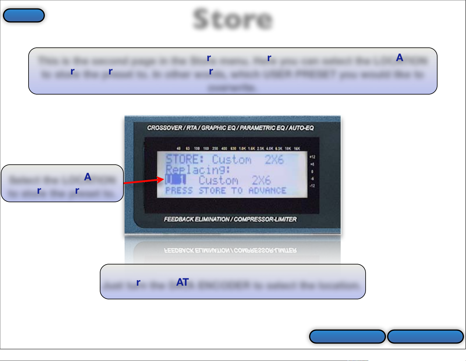
Prev Slide Next Page
This is the second page in the Store menu. Here you can select the LOCATION
to store the preset to. In other words, which USER PRESET you would like to
overwrite.
Just turn the DATA ENCODER to select the location.
Select the LOCATION
to store the preset to.
Store
Index
68
Page 69

The third press of the STORE button actually stores your preset with the name
that you selected & at the location which you selected. The preset location that
you stored to will automatically be loaded.
Back To Store Prev Slide
The preset (or program)
is being STORED to
memory.
Store
Index
69
Page 70

Wizard
This is the WIZARD button. Press this button to enter the Wizard.
Back To Buttons More Info
Index
70
Page 71

This is the WIZARD menu. Here you can enter the SYSTEM SETUP WIZARD
(step 1), AUTO EQ WIZARD (step 2), or AFS WIZARD (step 3).
Back To Wizard
Just turn the DATA ENCODER to make the selection.
Then press the NEXT PG button to proceed.
Select the SYSTEM
SETUP WIZARD.
Select the AUTO EQ
WIZARD.
Select the AFS
WIZARD.
Wizard
Index
71
Page 72

Data Encoder
This is the DATA ENCODER. Turning it will change the currently selected
parameter. It is also the SELECT button when pressed in. Pressing it in will move
the arrow (cursor) in the display. In other words it allows you to “Select” the
parameter that you would like to edit within the currently selected page then turn
the DATA ENCODER to change that parameter.
Back To Virtual PA
Index
72
Page 73

Input Meters
These are the INPUT METERS measured using the dBu scale. These meters
show the level of the audio that is driving the input stage of the DriveRack PA.
Note: The +20 (red) LEDs at the top of the LED meters are your clip indicators.
Back To Virtual PA
Index
73
Page 74

Limiter Threshold LEDs
These are the OUTPUT LIMITER THRESHOLD indicators. They give you a visual
indication when the output limiters are engaged.
Note: These LEDs do not indicate clipping. The +20 (red) LEDs at the top of the
meters are the clip indicators.
Back To Virtual PA
Index
74
Page 75

These are the OUTPUT METERS measured using the dBu scale. These meters
show the level of the audio that is driving the output stage of the DriveRack PA.
Output Meters
Note: The two far left meters correlate to the “Low” outputs, the two in the
middle are for the “Mid” outputs & the two on the right are for the “High”
outputs. The +20 (red) LEDs at the top of the meters are your clip indicators.
Back To Virtual PA
Index
75
Page 76

This is the POWER SWITCH. This turns the DriveRack PA on & off.
Power Switch
Note: Always remember to turn your amps on last and off first.
Back To Virtual PA
Index
76
Page 77
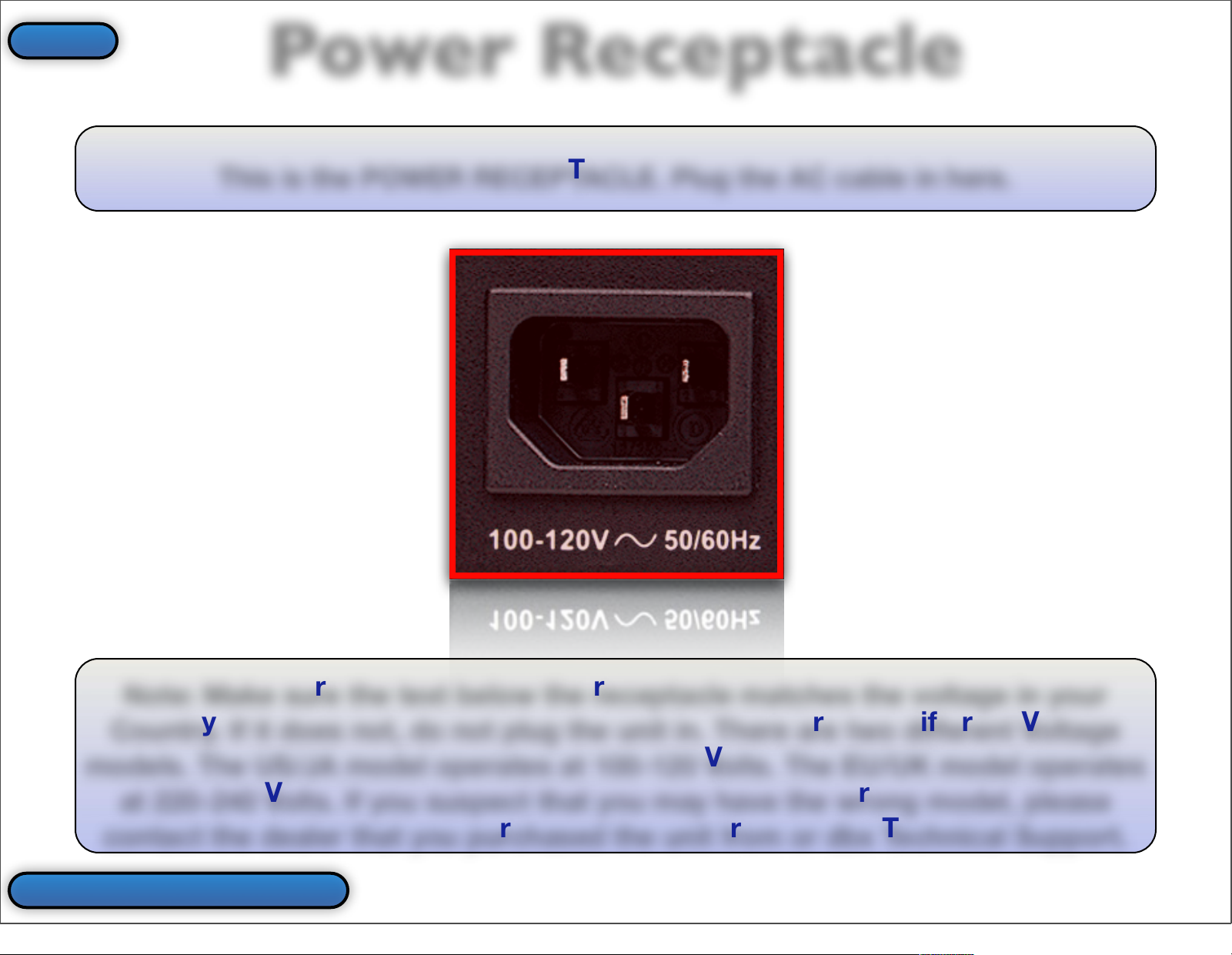
This is the POWER RECEPTACLE. Plug the AC cable in here.
Power Receptacle
Note: Make sure the text below the receptacle matches the voltage in your
Country. If it does not, do not plug the unit in. There are two different Voltage
models. The US/JA model operates at 100-120 Volts. The EU/UK model operates
at 220-240 Volts. If you suspect that you may have the wrong model, please
contact the dealer that you purchased the unit from or dbx Technical Support.
Back To Virtual PA
Index
77
Page 78
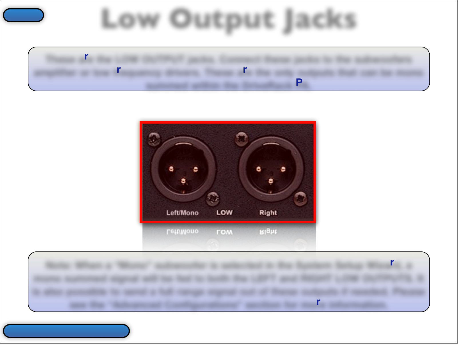
These are the LOW OUTPUT jacks. Connect these jacks to the subwoofers
amplifier or low frequency drivers. These are the only outputs that can be mono
summed within the DriveRack PA.
Low Output Jacks
Note: When a “Mono” subwoofer is selected in the System Setup Wizard, a
mono summed signal will be fed to both the LEFT and RIGHT LOW OUTPUTS. It
is also possible to send a full range signal out of these outputs if needed. Please
see the “Advanced Configurations” section for more information.
Back To Virtual PA
Index
78
Page 79

These are the MID OUTPUT jacks. Connect these jacks to the mid frequency
drivers amplifier when using a 3-Way system.
Mid Output Jacks
Note: It is possible to make these jacks output a full range signal.
Back To Virtual PA
Index
79
Page 80
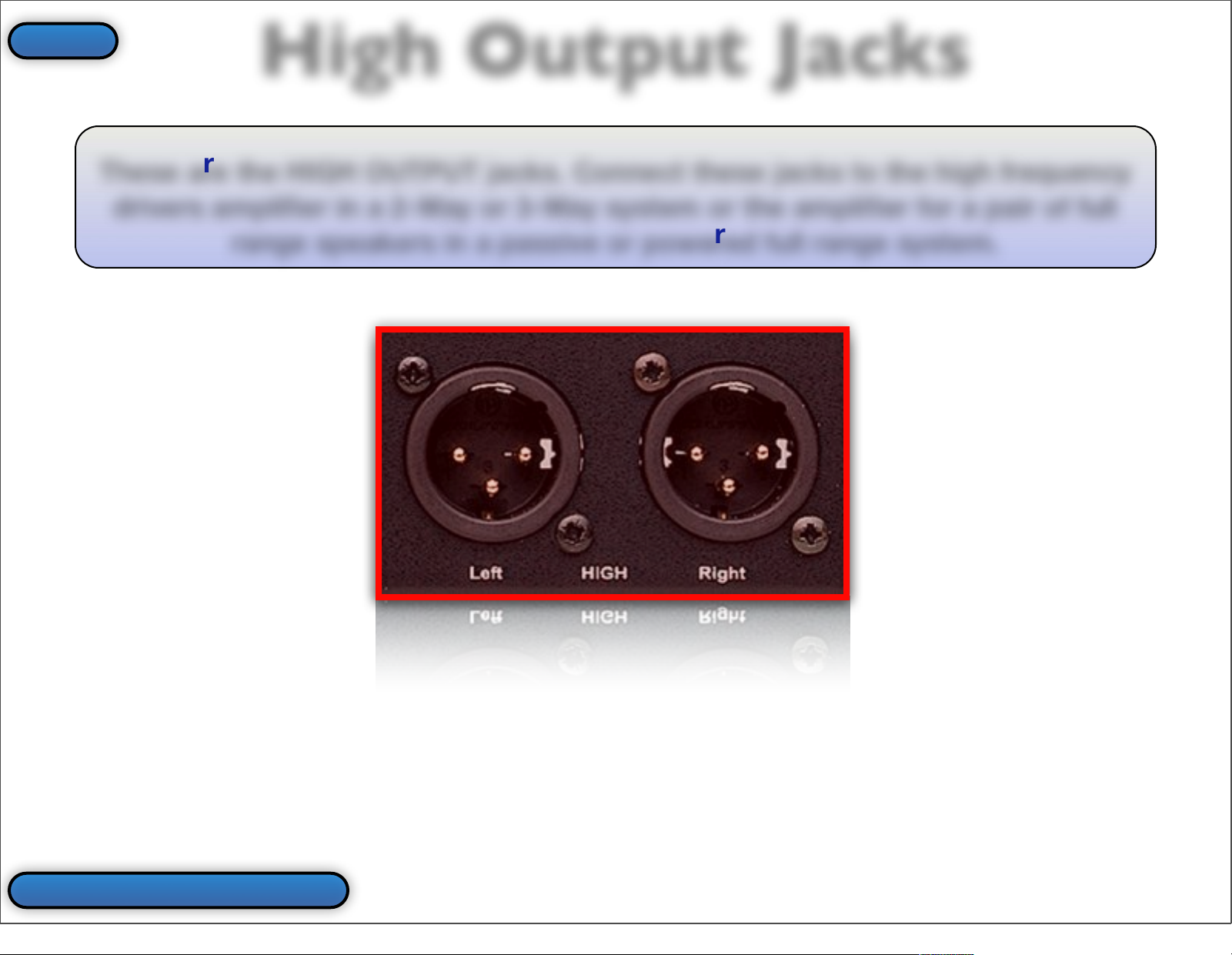
These are the HIGH OUTPUT jacks. Connect these jacks to the high frequency
drivers amplifier in a 2-Way or 3-Way system or the amplifier for a pair of full
range speakers in a passive or powered full range system.
High Output Jacks
Back To Virtual PA
Index
80
Page 81

This is the NOMINAL OPERATING LEVEL switch. This should be set to match
the operating level of the device that is plugged into the DriveRack’s inputs (this
is typically a mixer).
Operating Level Switch
Note: The selections for the nominal operating level are +4 dBu and -10 dBV. If
you are unsure what the operating level of your mixer is, please contact the
mixer manufacturer. Also, see the gain structure section in the “Setup” section of
this guide.
Back To Virtual PA
Index
81
Page 82

These are the INPUT jacks. They have a selectable nominal operating level of
+4 dBu or -10 dBV. Connect these jacks to the device pre DriveRack (typically a
mixer).
Input Jacks
Back To Virtual PA
Index
82
Page 83

This is the PIN 1 LIFT switch. If you are having problems with ground loops (i.e.
hum), try pressing this switch in. This will break the connection between the
ground pin in the cable and the input jacks.
Pin 1 Lift Switch
Back To Virtual PA
Index
83
Page 84

Index
Back To Main Menu
•
AFS
•
AFS Wizard
•
Auto EQ Wizard
•
Auto EQ Plot
•
Block Diagram
•
Button Array
•
Comp/Limiter Button
•
Compressor
•
Crossover
•
Cursor
•
Data Encoder
•
Delay
•
Delay Button
•
EQ Button
•
Feedback Button
•
GEQ
•
High Output Jacks
•
Input Configuration
•
Input Jacks
•
Input Meters
•
LCD Contrast
•
LCD Display
•
Limiter
•
Limiter Threshold LEDs
•
Low Output Jacks
•
Mid Output Jacks
•
Navigation
•
Next Page Button
•
Operating Level Switch
•
Output Meters
•
Overview
•
PEQ
•
Pin 1 Lift Switch
•
Power Receptacle
•
Power Switch
•
Preset Name
•
Preset #
•
Previous Page Button
•
Program Button
•
RTA Input Button
•
RTA Input Jack
•
Store Button
•
Subharmonic Button
•
Subharmonic Synthesis
•
System Diagram
•
System Setup Wizard
•
Threshold LEDs
•
Utility Button
•
Wizard Button
•
Xover
•
Xover Button
84
 Loading...