


System Components
1. IN T R O D U C T I O N
The Weather Wizard III provides sophisticated monitoring and logging of essential weather conditions such as inside and outside temperature, wind direction, wind speed and wind chill. This instruction manual takes you step- by-step through the process of assembling, testing, and installing your Weather Wizard III so you can begin collecting data as soon as possible.
The standard station comes with all the sensors necessary to monitor the essential weather conditions described above. For instructions on how to install and operate optional accessories, such as the Rain Collector, please refer to the appropriate manual.
If you have a non-standard station (e.g., Wireless or EZ-Mount), please refer to the separate installation manual provided before continuing with this installation.
SYSTEM COMPONENTS
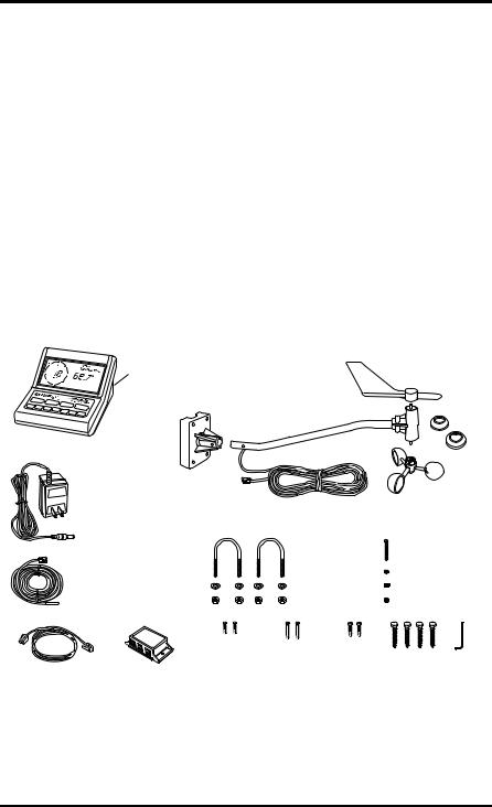
Your Weather Wizard III consists of the following components. Please check to be sure you have all of the components listed before proceeding.
Mounting Base |
|
|
(attached to |
|
Wind Vane |
bottom |
|
|
of Console) |
Anemometer Arm |
Drip |
|
with 40 feet (12.2 meters) |
|
|
of cable |
Rings |
Weather Station Console
Anemometer
Base Wind Cups
AC Power
Adapter
|
Cable Labels |
|
|
|
4–40 x 1-1/8" Pan Head |
|
|
(not shown) |
|
|
|
||
|
|
1 1/2" U-Bolts |
Self-Threading Screw |
|||
|
|
|
||||
External Temperature Sensor |
|
|
|
#4 Flat Washer |
||
|
1/4" Flat Washers |
#4 Lock Washer |
||||
with 25 feet (7.6 meters) |
|
|||||
|
of cable |
|
1/4"– 20 Hex Nuts |
4–40 Hex Nut |
||
|
|
#6 x 1/2" |
#6 x 1" |
#8 x 3/4" |
1/4" x 1-1/2" |
Allen |
|
|
Pan Head |
Pan Head |
Pan Head |
||
Junction Box Cable |
Junction Box |
Self-Threading |
Self-Threading Self-Threading |
Lag Screws |
Wrench |
|
8 feet (2.4 meters) long |
|
Screws |
Screws |
Screws |
|
|
Weather Wizard III |
Page 1 |

Introduction
OPTIONAL ACCESSORIES
The following accessories are designed for use with the Weather Wizard III.
•Rain Collector
Enables you to measure daily and accumulated rainfall. Separate models measure rainfall in either 0.01 inch or 0.2 mm increments. Optional Rain Collector Heater allows you to measure freezing rain or the moisture content of snowfall.
•WeatherLink® Software and Data Logger
Logs data gathered by the Weather Wizard III, downloads it to your PC or Macintosh®, and generates reports and graphical displays of your weather data.
•Car/Boat/RV Lighter Cord
Uses the cigarette lighter in your car, RV, truck, or boat to power the Weather Wizard III. Replaces the standard AC-power adapter.
•Sensor Mounting Arm
A single-location mounting option for all your sensors. Includes positioning for anemometer, external temperature sensor (with Radiation Shield), and Rain Collector (with Rain Collector Shelf).
•Radiation Shield
Protects the temperature sensor from the effects of the sun’s radiated and reflected heat. Increases the life of the sensor and the accuracy of the readings.
•Protected Junction Box
Provides upgraded protection against radio frequency interference (RFI), electrostatic discharges (ESD), and power surges that can come through sensor wires. Replaces junction box included with the station.
•Extension Cables
Extends cable length for total cable runs of 80-140 feet (24-42 m) sensor to console. Order the 4-Conductor Extension Cable [in lengths of 40 feet (12 m) or 100 feet (30 m)] for use with the anemometer, external temperature sensor, Rain Collector, or WeatherLink.
•Junction Box Cables
Order a Standard 8-Conductor Cable for greater flexibility in the placement of your console. Comes in lengths of 25, 50, and 100 feet (7.6, 15.2, and 30.4 m).
Page 2 |
Weather Wizard III |

Tools and Materials Needed for Installation
TOOLS AND MATERIALS NEEDED FOR INSTALLATION
In addition to the enclosed components, you will need the following tools and materials to complete the installation. Please be sure you have everything you need before proceeding with the installation.
•Cable clips or weather-resistant cable ties—with screw holes or other means for mounting
•Small and medium-sized screwdrivers
•Hand-held magnetic compass or local area map
•Hammer
•Small adjustable wrench
•Duco® Cement (or similar adhesive or glue for gluing plastic). Note that we do not recommend the use of “super glue” type products.
Optional Tools and Materials
•9-volt alkaline battery to be used as backup power supply (page 6)
•Carpenter’s level to level the anemometer base (page 10)
•Electric drill with 3/16” (4.8 mm) and/or #29 (0.136” or 3.5 mm) drill bits to drill pilot holes (page 10 and page 13)
•Electric tape if mounting the anemometer on metal mast or pipe (page 11)
•2 stainless steel hose clamps if mounting the anemometer on pipe with diameter greater than 1 1/4” (32 mm) (page 11)
•Standard switch box if mounting the console with the wires running inside the wall (page 14)
•Medium Phillips screwdriver if mounting the console on a wall (page 15)
Weather Wizard III |
Page 3 |

Introduction
A TYPICAL INSTALLATION
RainColllector (optional)
Anemometer
WEATHERWIZARDIIII
External Temp--
erature
Sensor  ToWeatherLink (optional)

 RAIN
RAIN
TEMP |
WEATHER WEATHER COMPUTER COMPUTER |
WIND |
|
NORTHSIDEOFBUILDINGininNorthernHemisphere
JunctionBox
SOUTHSIDEOFBUILDINGininSouthernHemisphere
ACPower
Adapter
Power
Outlet
JunctionBox
Cable
The diagram above shows a typical Weather Wizard III installation. The following pages will give you specific instructions for installing your station. To avoid unnecessary problems, be sure to thoroughly test your system before installing it.
WARNING: Climbing on your roof can be hazardous. If you are uneasy about installing your unit, please have a qualified professional complete the installation. Davis specifically disclaims any liability for injury or loss resulting from the installation or use of the Weather Wizard III.
|
|
|
|
|
|
Page 4 |
Weather Wizard III |

Powering the Weather Wizard III
2. AS S E M B L I N G T H E ST A T I O N
The Weather Wizard III is a precision instrument, designed to give extremely accurate readings. As with any precision instrument, care must be used during assembly. These instructions detail how to assemble the stations with a minimum of time and effort.
POWERING THE WEATHER WIZARD III
The Weather Wizard III is powered by 9- to 12-volt DC (direct current). In North America, the power adapter included with your unit converts 120-volt, 60-Hz AC (alternating current) to 9-volt DC, allowing you to run the unit on ordinary household current. You may also run the Weather Wizard III on the 12-volt DC power supplied by a car, boat, or RV battery by using the optional Car/Boat/RV Lighter Cord.
If you are outside North America and in a location where the power supply is not equivalent to the North American standard (120-volt, 60-Hz), check to see if your local dealer has supplied a power adapter that is appropriate for your power supply before you connect the power adapter to the console. If not, you must use a power converter/transformer or the appropriate power adapter (9- volt, 2.5-mm female plug).
In any case, we recommend that you also install a 9-volt alkaline battery as a backup power supply. In the event of a power outage, the battery will power the station. Not only will this prevent the loss of stored data in the console, but will also allow you to continue observing weather conditions during the power outage.
New alkaline batteries will power the Weather Wizard III for 24 - 48 hours. For maximum security, keep the battery backup fresh. You should replace batteries any time the unit has operated on battery power for more than 18 hours. To prevent loss of data when replacing batteries, make sure the unit is receiving power from the adapter before changing batteries.
Note: We do not recommend the use of Ni-Cad batteries. Ni-Cad batteries carry less power than alkaline batteries, and they will not be recharged by the station. In the event of a power outage, Ni-Cad batteries will be able to power the station for a shorter period of time than alkaline batteries will.
To Connect the Power Adapter to the Console
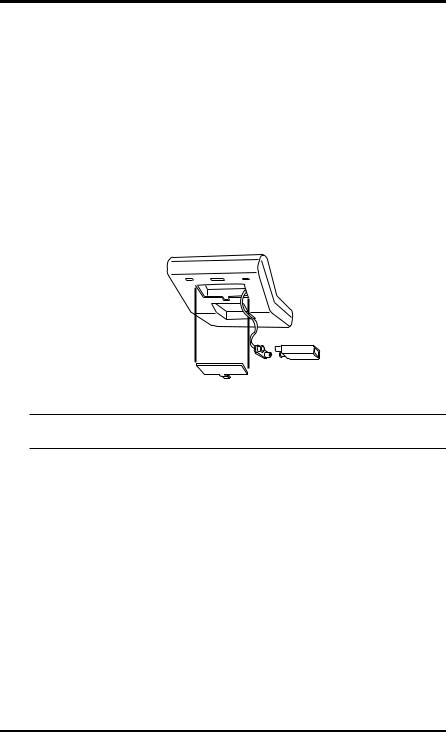
1.Remove the mounting base from the console.
Push down on the large tab behind the display until it will easily slide out from the notch. Then lift the mounting base so the two smaller tabs behind the keyboard slide free. Place the mounting base aside until you mount the console (see “Displaying the Console” on page 14).
2.Slide the power adapter plug into the jack marked POWER underneath the console.
Weather Wizard III |
Page 5 |
Assembling the Station
3.Plug the other end of the power adapter into an appropriate power outlet or, preferably, into a computer-grade surge protector.
It is highly recommended that you plug the power adapter into a computer-grade surge protector, especially in lightning-prone areas. Once power is applied, the console should run through a brief self-test procedure. All of the display segments appear, and the console beeps twice within 10 seconds (3 times within 20 seconds if WeatherLink is installed) to indicate everything is working properly.
After the second beep (or the third beep with WeatherLink), the compass rose and the time (reading 12:00 a.m.) appear on the display.
To Install the Battery Backup Power Supply
Before you install the backup battery, make sure AC power is connected and the console is completely powered up. Installing the battery first can cause the console to lock up.
Once the console is powered up, install the backup battery as shown below.
Underside
of Console 
Battery |
Standard |
Cover |
|
|
9-Volt Alkaline |
Release |
Battery |
Tab |
|
Note: When the unit is operating on battery power, the digits on the right side of the display blink on and off. The unit operates normally in all other respects.
CONNECTING THE CONSOLE AND JUNCTION BOX
The junction box is the connecting point between the external sensors and the console. Information from the sensors comes into the junction box. The junction box then relays that information to the console where it is processed and displayed.
To Connect the Console and Junction Box
1.Plug one end of the 8-foot (2.4-meter) long junction box cable into the jack labeled JUNCTION BOX underneath the console.
2.Plug the other end of the cable into the jack marked CONSOLE on the junction box.
Page 6 |
Weather Wizard III |
Assembling the Anemometer
ASSEMBLING THE ANEMOMETER
To assemble the anemometer you will need the following: anemometer arm (with cable), anemometer base, wind cups, drip rings, allen wrench, 4-40 x 1 1/8-inch pan head screw, #4 flat washer, #4 lock washer, and 4-40 hex nut.
Avoid lubricating the wind cup shaft and bearings or the wind vane shaft. Natural or synthetic lubricant affects the normal operation of the anemometer by reducing the component's efficiency. It also may attract insects which can jam moving parts.
Note: Do NOT attach the wind vane at this time. Wait until you have installed the anemometer (see page 11) before attaching wind vane.
To Attach the Anemometer Arm to the Anemometer Base
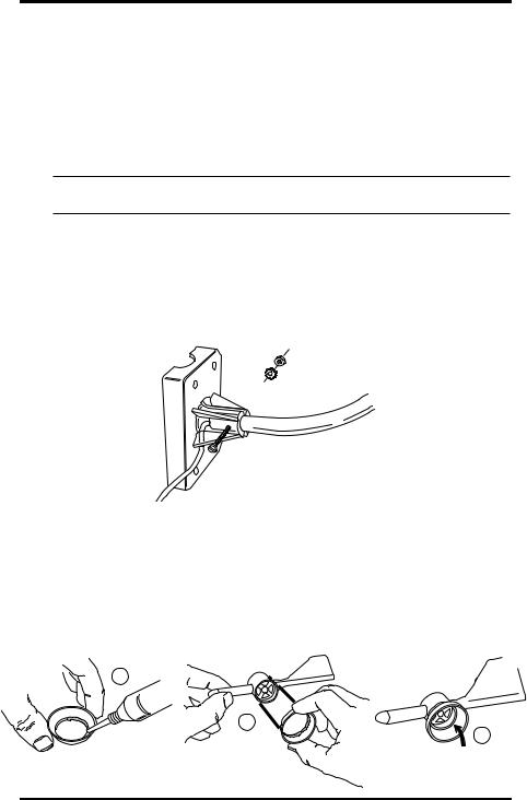
1.Insert the anemometer arm into the anemometer base, sliding cable through the slot in the base as shown. Line up the small hole in the arm with the holes in the base.
2.Insert the 4-40 screw into one of the holes in the base and through the arm.
The screw should slide easily through the holes.
3.Secure as shown below.
4-40 Hex Nut
#4 Lock Washer
 #4 Flat Washer
4-40 x 1" Pan Head Screw
To Attach the Drip Rings to the Wind Vane and Anemometer Arm
The drip rings provide excellent protection against icing of the wind vane and wind cups. If you choose not to install them, however, the anemometer will function normally in non-icy conditions.
1.Apply adhesive liberally to the inside of one of the drip rings and install on the wind vane as shown below.
Make sure the lower edge of the drip ring is approximately parallel to the bottom of the wind vane.
Wind Vane
A
B
Duco Cement |
Drip Ring |
|
Drip Ring
C
Lower edge of inside ring (approximately parallel to bottom of wind vane)
Weather Wizard III |
Page 7 |
Assembling the Station
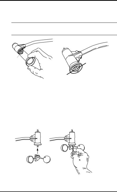
2.Apply adhesive liberally to the inside of the other drip ring and install on the WIND CUP END OF THE ANEMOMETER CONTROL HEAD as shown below.
The wind cup end of the control head is the smaller of the two stainless steel shafts.
Note: When attaching drip ring, make sure the lower edge of the ring is aligned with the lower edge of the control head. If the drip ring extends below the lower edge of the control head, the wind cups will not have room to slide on.
Control Head
Smaller Shaft |
Lower edge of outside ring |
(aligned with lower edge of control head)
3.After the cement has properly cured (according to the cement’s direction), follow the instructions below to attach the wind vane and wind cups to the anemometer.
To Attach the Wind Cups to the Anemometer Arm
1.Push the wind cups onto the smaller of the two stainless steel shafts at the end of the arm.
2.Slide the wind cups as far up the shaft as possible.
3.Use the allen wrench provided to tighten the set screw on the side of the wind cups.
Note that when you let go of the wind cups, they should drop slightly.
4.Spin the wind cups. If they do not spin freely, loosen the set screw and lower the cups slightly. Repeat until the wind cups spin freely.
Push cups onto |
Tighten set screw |
stainless steel |
with allen wrench |
shaft |
|
Page 8 |
Weather Wizard III |

Testing the Anemometer
3. TE S T I N G T H E ST A T I O N
Before continuing with the installation, test the station in your living room or workshop. If you have purchased the optional rain collector or additional sensors, now is the time to assemble and test these using the appropriate manual. Consult the Troubleshooting Guide on page 32, or the guides in the respective manuals, if you experience any difficulty.
Note: You should test each external sensor without extension cables first, and then repeat the test with extension cables. In this way, you can be reasonably sure whether any problems are the fault of the extension cables or the external sensor itself.
TESTING THE ANEMOMETER
Before you install the anemometer, make sure that the wind speed and wind direction sensors are functioning correctly.
1.Insert the cable plug at the end of the anemometer cable into the jack marked WIND on the junction box.
2.Test your assembly by spinning the wind cups.
You should get a speed reading other than 0 on the compass rose in the console display. If you do not, loosen the set screw and move the wind cups slightly up or down on the shaft until you get a reading other than 0. Once you are getting a reading, use the allen wrench provided to tighten the set screw on the side of the wind cups. Do not over-tighten.
3.Turn the wind direction shaft (the larger of the two stainless steel shafts on the control head) with your fingers.
Check that the direction readings change on the compass rose in the console display.
TESTING THE EXTERNAL TEMPERATURE SENSOR
Using the steps below, check to see that you get a reading from the external temperature sensor as well.
To Test the Temperature Sensor
1.Insert the cable plug at the end of the external temperature sensor into the jack marked TEMP on the junction box.
2.Press TEMP on the console.
A temperature reading and the words INSIDE and TEMPERATURE should appear on the display.
3.Press TEMP again.
A temperature reading and the words OUTSIDE and TEMPERATURE should appear on the display.
Weather Wizard III |
Page 9 |
Installing the Station
4. IN S T A L L I N G T H E ST A T I O N
Make sure you have thoroughly tested the station before installing it. Then, decide where you will place each component—the junction box, the console, and all external sensors. Pay close attention to the suggestions given in the sections dealing with the individual components, as well as the following general suggestions:
•The junction box cable must be able to reach the console.
If you want to place the junction box and console more than 8 feet (2.4 m) apart, you will need a longer junction box cable (see page 2).
•The cable coming from each external sensor must be long enough to reach the junction box.
To prevent wind damage, leave some slack to allow the cables to be secured to available surfaces. If the sensors are placed farther away than their allotted cable lengths allow, use extension cables (see page 2).
INSTALLING THE ANEMOMETER
Most people install the anemometer on the roofs of their houses, where wind flow is unobstructed by trees and nearby buildings. For the most representative readings, the anemometer should be mounted at least 4 feet (1.2 m) above the roof line. You can do this by mounting the anemometer on your television antenna or on a raised piece of wood or metal pipe.
We have included the hardware most commonly needed for the installation of the anemometer. The hardware you use depends upon where you install your unit. You may need to adapt or purchase additional hardware to fit your individual requirements.
To Install the Anemometer
1.Disconnect the anemometer cable from the junction box.
2.Wrap the WIND cable labels around each end of the cable.
3.Mount the anemometer according to the following instructions. As you do so, use a carpenter's level to make sure the anemometer base is mounted vertically.
WOODEN POST OR SURFACE
1.Locate a suitable mounting surface for the anemometer base. The mounting surface should be at least as wide as the anemometer base and level.
2.Hold the anemometer base against the wood surface
and use a pencil to mark the location of the four holes on the base.
3. Use an electric drill with a 3/16 inch (4.8-mm) drill bit to make pilot holes in these locations.
4.Drive the four lag screws through the holes in the anemometer base and into the wood.
Page 10 |
Weather Wizard III |
Installing the Anemometer
ANTENNA MAST OR METAL PIPE - OUTSIDE DIAMETER 3/4 TO
1 1/4 INCHES (19 TO 32 MM)
1. Make sure that the antenna mast or metal pipe is properly grounded. If you are not sure, consult a qualified professional.
2. Hold the anemometer base against the pipe and insert the two U-bolts through the back of the base so that the U-bolts wrap around the pipe.
3. Place a 1/4-inch washer and a 1/4-20 hex nut over each end of the U-bolts. Use a wrench to tighten the hex nuts.
METAL MAST OR PIPE - OUTSIDE DIAMETER GREATER THAN 1 1/4 INCHES (32 MM)
1. |
Obtain two stainless steel hose clamps large enough to fit |
|
|
|
around the mast or pipe and the anemometer base. These can |
Metal Pipe |
|
|
be purchased at your local hardware store. |
Hose Clamps |
|
2. |
Make sure that the metal mast or pipe is properly grounded. If |
||
|
you are not sure, consult a qualified professional.
3.Hold the anemometer base against the pipe and fasten the hose clamps over the anemometer base and around the metal mast or pipe.
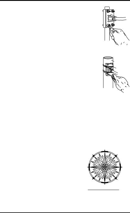
To Attach the Wind Vane
To mount the wind vane, you will need to look at the console display. You may wish to have a friend or family member on the ground do this for you. Or, you may wish to bring the console and junction box onto the roof with you.
1.After installing the anemometer, re-insert the plug at the end of the anemometer cable into the jack marked WIND on the junction box
2.Press WIND on the console until a wind direction reading and the word DIRECTION appear on the display.
3.Use a compass or local area map to determine which direction (N, S, E, W, NE, etc.) the anemometer arm is pointing.
4.Use the wind direction chart to find the degree reading which corresponds to that direction.
5.Slowly turn the wind direction shaft with your fingers. Stop turning when the console display reaches the degree reading obtained in
step 4.
|
0° N |
315° NW |
45° NE |
270° W |
90° E |
6.Being careful to keep the stainless steel shaft from turning, place the wind vane on the shaft with the bullet-shaped nose of the vane pointing in the same direction as the arm. Leave approximately a 1/16-inch (1.5-mm) gap between the base of the wind vane and the arm.
225° SW |
135° SE |
180° S
WIND DIRECTION CHART
Weather Wizard III |
Page 11 |
 Loading...