


User’s
Guide
INDEX SHADES |
|
INDEX MIRROR |
HORIZON MIRROR (Beam Converger on Mark 25 only)
HORIZON
SHADES
MICROMETER
DRUM
QUICK RELEASE
LEVERS LED ILLUMINATION (Mark 25 only)
ADJUSTMENT SCREW
TELESCOPE
INDEX ARM |
|
|
|
|
|
|
|
|
|
|
STANDARD |
|
DELUXE |
|
|
MARK 15 |
|
MARK 25 |
|
|
#026 |
|
#025 |
|
|
|
|
|
|

Replacement Parts
Contact your local dealer or Davis Instruments to order replacement parts or factory overhaul.
Mark 25 Sextant, product #025
R014A |
Sextant case |
R014B |
Foam set for case |
R025A |
Index shade assembly (4 shades) |
R025B |
Sun shade assembly (3 shades) |
R025C |
3× telescope |
R026J |
Extra copy of these instructions |
R025F |
Beam converger with index mirror, springs, screws, nuts |
R025G |
Sight tube |
R026D |
Vinyl eye cup |
R026G |
8 springs, 3 screws, 4 nuts |
R025X |
Overhaul |
Mark 15 Sextant, product #026 |
|
R014A |
Sextant case |
R014B |
Foam set for case |
R026A |
Index shade assembly (4 shades) |
R026B |
Sun shade assembly (3 shades) |
R026C |
3× telescope |
R026D |
Vinyl eye cup |
R026G |
8 springs, 3 screws, 4 nuts |
R026H |
Index and horizon mirror with springs, screws, nuts |
R026J |
Extra copy of these instructions |
R026X |
Overhaul |
R026Y |
Sight tube |
Master Sextants User’s Guide
Products #025, #026
© 2008 Davis Instruments Corp. All rights reserved.
00026.710, Rev. F October 2008

USING YOUR DAVIS SEXTANT
This booklet gives the following information about your new Davis Sextant:
•Operating the sextant
•Finding the altitude of the sun using the sextant
•Using sextant readings to calculate location
•Other uses for the sextant
To get the most benefit from your sextant, we suggest you familiarize yourself with the meridian transit method of navigation. A good basic reference book is
Practical Celestial Navigation by Susan P. Howell (Mystic Seaport Publications, 1987). Further discussion of this method of navigation is beyond the scope of this booklet.
OPERATING THE SEXTANT
There are three steps to adjusting your sextant: index mirror adjustment, horizon mirror adjustment, and index error adjustment and calculation. The index arm of the sextant can move in relation to the body by turning the micrometer drum or by squeezing the spring-loaded quick release levers. The levers free the fine adjustment screw in the interior of the index arm and allow it to be moved quickly to any angle. Be sure to squeeze the levers completely so that the screw clears the gear rack on the underside of the sextant. Release the levers and turn the micrometer drum at least one full turn to ensure that the screw has meshed fully with the gear rack. An incorrect reading may be obtained at the drum if this is not done.
Note: Every sextant exhibits some difference in readings when turning toward higher or lower angles (called backlash error). Always make the final movement of the knob toward a higher angle.
Reading the Sextant Scales
The Davis Mark 15 and Mark 25 sextants have three scales that give readings to 2/10 of a minute. The scale on the frame is called the “arc”; each division of the arc equals one degree.
To read the number of degrees:
Find the lines on the arc that are closest to the index line on the index
arm.
The index line is usually somewhere between two lines. The correct reading is usually that of the lower value, i.e., the line to the right of the index line.
Note: When the index line is very close to a line on the arc, check the reading at the micrometer drum to be sure that you have taken the correct whole degree.
Page 1
To read fractions of a degree:
Use the two scales involving the micrometer drum at the side of the
index arm.
The outer revolving drum scale indicates minutes of arc (one minute equals 1/60 of a degree), while the stationary vernier reads to 2/10 of a minute.
To read the number of minutes:
Find the single LONG line at the top of the vernier.
The line on the drum scale that is opposite this line gives the number of minutes. If the line on the vernier is between two lines on the drum, choose the line of lower value.
To read fractions of a minute:
1.Find the SHORT line of the vernier that is opposite to a line on the drum.
2.Count the number of spaces this line is away from the long line at the top of the vernier. Each one equals 2/10 of a minute.
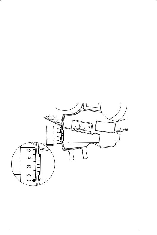
Figure 1
In this diagram (Fig. 1), the line on the vernier that is opposite to a line on the drum is two spaces away from the long line at the top of the vernier. The sextant reads 45°16.40'.
Note: The micrometer drum scale and its screw mechanism, not the arc, determine the accuracy of your sextant. The arc is stamped with sufficient accuracy to ensure that you are never reading the incorrect whole degree; full accuracy in minutes of arc depends exclusively on the drum scale. For example, when the sextant reads 0° 00', the drum scale will be set precisely at zero, while the index line and the zero on the arc may be slightly out of alignment. As you are concerned only with reading whole degrees on the arc, this difference is not significant.
Page 2

Using the Light on the Davis Mark 25 Sextant
The Mark 25 is specially constructed with a solid state light emitting diode (LED)
and light guide to allow easy reading of the scales at twilight.
To use the light:
Make sure that your eyes are dark-adapted before using the light.
Press the button at the top of the handle.
The light turns off when the button is released.
Note: The high-efficiency LED configuration was developed to insure long battery life (as much as ten times longer than with regular bulbs). Nevertheless, all batteries eventually run down. When not using your sextant for long periods of time, remove the batteries by unscrewing the black plastic screw in the handle. Battery contacts can be easily cleaned with a small file or knife blade. Replacements, if needed, are ordinary zinc-carbon or alkaline batteries, 1.5 volt, size AAA. Batteries that start to leak should be removed immediately. After replacing the batteries, be sure to fit the handle together again carefully, and replace the screw snugly but not too tight.
Inserting the 3X Telescope
Your sextant comes equipped with a high quality 3X telescope. The scope is inter-
changeable with the hooded sight tube.
To remove the sight tube from its mounting bracket on the sextant:
Separate the tube from the eye-piece as shown in Fig. 2 below.
Figure 2
CAUTION: Do not attempt to snap the assembled sight tube into or out of the mounting bracket. Separate the sight tube from the eyepiece by carefully sliding the eyepiece out of the bracket and from the rear only. Insert the scope from the front only.
Page 3

Adjusting for and Calculating Built-In Index Error
Adjusting your sextant is easy and should be done each time it is used. On a correctly adjusted sextant, the two mirrors are always perpendicular to the frame and become parallel to each other when the body and drum scales read zero.
To initially adjust the index mirror so that it is perpendicular to the frame:
1.Set the instrument at approximately 50°.
2.Holding the sextant horizontal and about eight inches from the eye, look with one eye into the mirror so that the frame arc is reflected in the mirror.
3.Move the instrument until you can look past the index mirror and see the actual frame arc as well as the reflected arc.
The two arcs should appear as one continuous curve (Fig. 3). If they do not, turn the adjustment screw at the back of the index mirror until the two arcs come into alignment.
Figure 3
To adjust the sextant for index error:
1.Set the instrument at 0° 00' and look at the horizon.
2.Keeping the sextant close to your eye, turn the screw that is furthest from the frame at the back of the horizon mirror until the two horizon images move exactly together (Fig. 4).
The two mirror are now parallel.
Figure 4
Page 4

3.To be certain that the sextant is now correctly adjusted, check to see that the sextant is still set at 0° 00' and the real and reflected horizons remain in a single line when the instrument is rocked or inclined from side to side (Fig. 5).
On a correctly adjusted sextant, the real and mirror horizons remain in a single line when the instrument is rocked from side to side.
Figure 5
While you should know how to adjust your sextant for index error, it is not necessary to remove it entirely. It is standard practice to simply note the error and then correct one’s readings for this amount each time the sextant is used (6' or so of index error is allowable).
To calculate the index error:
1.Hold the sextant in your right hand and look at the sea horizon.
2.By moving the index arm and the micrometer drum, line up the real and mirror horizons so that both appear as a single straight line.
3.Read the sextant scales.
If the sextant reads 0° 00', there is no index error. If the sextant reads anything but zero, there is an index error, which must be added to or subtracted from each subsequent sight.
For example:
If the sextant reads 6', the 6' is subtracted; if the sextant reads –6', the 6' is added. For an index error of –6', the micrometer drum will read 54'.
Page 5

To adjust the horizon mirror (Mark 15 only):
1.Adjust the horizon mirror (the small, half-silvered mirror) for “side error” by making it perpendicular to the frame.
2.Holding the sextant in your right hand, raise the instrument to your eye.
3.Look at any horizontal straight edge (the sea horizon or the roof of a building, for example) and move the index arm back and forth.
The real horizon will remain still while the mirror horizon will appear only when the body and drum scales read close to zero.
4.Line up the mirror horizon and the real horizon so that both appear as a single straight line (Fig. 6).
Figure 6
5.Without changing the setting, look through the sextant at any vertical line (a flagpole or the edge of a building, for example) and slowly swing the instrument back and forth across the vertical line.
If the horizon mirror is not perpendicular to the frame, the line will seem to jump to one side as the mirror passes it. To correct this, slowly tighten or loosen the screw closest to the frame at the back of the horizon mirror until the vertical line no longer appears to jump (Fig. 7).
Figure 7
Page 6
 Loading...