


 Loading...
®

FCC Part 15 Class B Registration Warning
This equipment has been tested and found to comply with the limits for a Class B digital device, pursuant to Part 15 of the FCC Rules. These limits are designed to provide reasonable protection against harmful interference in a residential installation. This equipment generates, uses, and can radiate radio frequency energy and, if not installed and used in accordance with the instructions, may cause harmful interference to radio communications.
However, there is no guarantee that interference will not occur in a particular installation. If this equipment does cause harmful interference to radio or television reception, which can be determined by turning the equipment on and off, the user is encouraged to try to correct the interference by one or more of the following measures:
•Reorient or relocate the receiving antenna.
•Increase the separation between the equipment and receiver.
•Connect the equipment into an outlet on a circuit different from that to which the receiver is connected.
•Consult the dealer or an experienced radio/TV technician for help.
Changes or modification not expressly approved in writing by Davis Instruments may void the warranty and void the user's authority to operate this equipment.
FCC ID: IR2DWW6351 IC: 3788A-6351
EC EMC Compliance
This product complies with the essential protection requirements of the EC EMC Directive 2004/108/EC; Low Voltage Directive 2006/95/EC; and Eco-Design Directive 2005/32/EC >0.5 watt no-load adaptor.
RoHS Compliant
Vantage Vue Console Manual |
|
Document Part Number: 07395.261 |
Rev. F, August 22, 2013 |
For Vantage Vue Consoles #6351 |
|
And Vantage Vue Weather Stations #6250, 6357 |
|
Vantage Vue® and Vantage Pro2™ are trademarks of Davis Instruments Corp., Hayward, CA.
© Davis Instruments Corp. 2013. All rights reserved. Davis Instruments Quality Management System is ISO 9001 certified.
Information in this document subject to change without notice.


 ®
®
3465 Diablo Avenue, Hayward, CA 94545-2778 U.S.A.
510-732-9229 • Fax: 510-732-9188 E-mail: info@davisnet.com • www.davisnet.com

Table of Contents |
|
Welcome to Vantage Vue ................................................................................................ |
1 |
Console Features: Keyboard & Display ..................................................................... |
1 |
In This Manual ........................................................................................................... |
2 |
Vantage Vue System Installation Steps ...................................................................... |
2 |
Installing the Console ..................................................................................................... |
3 |
Powering the Console ................................................................................................ |
3 |
Installing Batteries ..................................................................................................... |
3 |
Installing the AC Power Adapter (Optional) ............................................................. |
4 |
Console Location ....................................................................................................... |
4 |
Table & Shelf Placement ........................................................................................... |
5 |
Wall Mounting ........................................................................................................... |
5 |
Using Your Weather Station ........................................................................................... |
6 |
Console Modes ........................................................................................................... |
6 |
Setup Mode ................................................................................................................ |
6 |
Setup Mode Commands ............................................................................................. |
6 |
Screen 1: Time & Date ............................................................................................... |
7 |
Screen 2: Time Zone .................................................................................................. |
7 |
Screen 3: Daylight Saving Settings ............................................................................ |
8 |
Screen 4: Daylight Saving Status ............................................................................... |
8 |
Screen 5: Active Transmitters .................................................................................... |
8 |
Screen 6: Configuring Transmitter IDs ...................................................................... |
9 |
Screen 7: Retransmit ................................................................................................ |
10 |
Screens 8 and 9: Latitude and Longitude ................................................................. |
10 |
Screen 10: Elevation ................................................................................................ |
11 |
Screen 11: Barometric Reduction Setting ................................................................ |
11 |
Screen 12: Wind Cup Type (Optional) .................................................................... |
12 |
Screen 13: Rain Collector ........................................................................................ |
12 |
Screen 14: Rain Season ............................................................................................ |
13 |
Screens 15 and 16: Cooling and Heating Degree Day Base .................................... |
13 |
Screens 17 and 18: Commentary and Key Beep ...................................................... |
14 |
Screen 19: Baud Rate (Optional) ............................................................................. |
14 |
Exiting Setup Mode ................................................................................................. |
15 |
Clear All Command ................................................................................................. |
15 |
Current Weather Mode ............................................................................................. |
15 |
Current Weather Mode Commands ......................................................................... |
16 |
Displaying Weather Variables ................................................................................. |
16 |
Time & Date, Sunrise & Sunset Time, Moon Phase, Forecast Icons ...................... |
17 |
Wind Speed and Direction ....................................................................................... |
17 |
Inside and Outside Temperature .............................................................................. |
18 |
Humidity .................................................................................................................. |
20 |
Barometric Pressure ................................................................................................. |
20 |
Pressure Trend .......................................................................................................... |
22 |
Wind Chill ................................................................................................................ |
22 |
i

Dew Point ................................................................................................................. |
22 |
Heat Index ................................................................................................................ |
23 |
Rain .......................................................................................................................... |
23 |
Evapotranspiration (ET) (Optional) ......................................................................... |
25 |
Weather Center ........................................................................................................ |
25 |
Light ......................................................................................................................... |
26 |
Selecting Units of Measure ...................................................................................... |
26 |
Calibrating, Setting, and Clearing Variables ........................................................... |
27 |
Calibrating Temperature and Humidity ................................................................... |
27 |
Calibrating Wind Direction Reading ....................................................................... |
27 |
Calibrating Barometric Pressure .............................................................................. |
28 |
Calibrating Rain ....................................................................................................... |
28 |
Setting Weather Variables ....................................................................................... |
28 |
Clearing Weather Variables Accumulations & Calibrations ................................... |
29 |
Clear All Command ................................................................................................. |
29 |
Highs and Lows Mode ............................................................................................. |
30 |
Viewing Highs and Lows ......................................................................................... |
30 |
Alarm Mode ............................................................................................................. |
31 |
Special Alarms ......................................................................................................... |
32 |
Setting Alarms ......................................................................................................... |
32 |
Setting the Time Alarm............................................................................................ |
33 |
Clearing Alarm Settings........................................................................................... |
33 |
Silencing Alarms ...................................................................................................... |
33 |
Changing Alarm Sound............................................................................................. |
33 |
Graph Mode ............................................................................................................. |
33 |
Viewing Graphs ....................................................................................................... |
34 |
Troubleshooting and Maintenance ................................................................................ |
36 |
Vantage Vue Troubleshooting Guide ...................................................................... |
36 |
Troubleshooting Reception Problems...................................................................... |
37 |
Check Console Reception ........................................................................................ |
38 |
Console Diagnostic Mode ........................................................................................ |
38 |
Diagnostic Screen Commands ................................................................................. |
38 |
Screen 1: Statistical Diagnostic Screen .................................................................... |
39 |
Screen 2: Reception Diagnostic Screen ................................................................... |
40 |
Console Maintenance ............................................................................................... |
41 |
Changing Batteries ................................................................................................... |
41 |
Console Firmware Versions ..................................................................................... |
41 |
One Year Limited Warranty .................................................................................... |
41 |
Contacting Davis Technical Support ....................................................................... |
41 |
Appendix A: Weather Data ........................................................................................... |
42 |
Appendix B: Specifications .......................................................................................... |
47 |
Appendix C: Wireless Repeater Configuration ............................................................ |
51 |
ii
Chapter 1
Welcome to Vantage Vue
The console of your new Vantage Vue wireless weather station displays and records your station’s weather data, provides graph and alarm functions, and interfaces to a computer using our optional WeatherLink® software.
Your Vantage Vue station also includes an outdoor Integrated Sensor Suite (ISS) that transmits outside sensor data to the console via a low-power radio. The console displays all the information coming from the ISS in an easy-to-use format. It can also receive data from a Davis Vantage Pro2™ weather station. The Vantage Vue Quick Reference Guide included with your station provides an easy-to-use reference for most console functions.
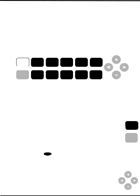
Console Features: Keyboard & Display
HEAT |
DEW |
CHILL |
ET |
LIGHT TEMP HUM WIND RAIN BAR
2ND WXCEN GRAPH HI/LOW TIME DONE
ALARM |
SET |
CLEAR |
UNITS |
SETUP |
Vantage Vue Keyboard
Use the keyboard to access and scroll through current and historical data for individual variables, set and clear alarms, enter calibration values, set up and view graphs, and view detailed weather information available for each variable.
The keyboard consists of 12 command keys and four navigation keys.
A weather variable or console command is printed on each command key. Just HEAT press a key to select the variable or function printed on that key.
TEMP
Each command key also has a secondary function which is printed above the
first row of keys or below the second row of keys. To select the secondary 2ND function, press and release 2ND and then immediately press the key for that
function.
After pressing 2ND, the 2nd icon displays above the moon phase icon on the screen indicating that all secondary key functions are enabled. Keys resume normal operation after the icon disappears (about 7-8 seconds).
The + and - navigation keys along with the < and > navigation keys are used to select command options, adjust values, and to provide additional functions when used in combination with a command key.
An arrow  appears next to the variable selected in the display.
1

Console Features: Keyboard & Display
In Current Weather Mode, the display shows the time and date, the likely forecast within the next 12 hours, current moon phase, and weather information for up to 8 different weather variables at a time. It also displays additional information pertinent to a selected variable in the Weather Center in the bottom right section of the console screen.
|
Time & Date |
Arrow shows |
Inside & Outside |
|
|
which variable |
|
||
|
Sunrise/Sunset |
is selected |
Temperature |
|
Moon phase, |
am |
|
F |
F |
alarm, & |
N |
INSIDE |
OUTSIDE |
Inside & Outside |
forecast icons |
NW |
NE |
|
Humidity |
Wind |
|
|
|
Barometric |
W |
E |
|
Pressure & Trend |
|
Compass Rose |
in |
|||
|
|
|
|
|
|
CHILL |
|
RAIN RATE |
|
Rain data & ET* |
Antenna icon |
SW |
SE |
F |
|
|
|
|
|
|
||||
shows active |
WIND |
S |
|
|
in/hr |
Wind Chill/Heat |
transmission |
|
|
|
|
||
|
|
|
|
|
Index/Dew Point |
|
|
|
|
|
|
|
|
Graph of |
|
|
|
|
|
Weather Center |
|
|
|
|
|
with additional |
|
selected variable |
|
|
|
|
|
|
|
|
|
|
|
information |
|
|
|
|
|
|
|
*ET, optional, available only when used with a Vantage Pro2 Plus or a Vantage Pro2 with Solar Radiation sensor.
In This Manual
This manual contains all the information you will need to power, set up, and use your console. It also includes a troubleshooting section for solving some basic console issues.
•See “Installing the Console” on page 3 for information on powering and placing or mounting your Vantage Vue console.
•See “Setup Mode” on page 6 for information on configuring and setting up your console.
•See “Current Weather Mode” on page 15 for information on displaying current weather information.
•See “Troubleshooting and Maintenance” on page 36 for information on troubleshooting console issues and routine maintenance.
Vantage Vue System Installation Steps
•Prepare the Integrated Sensor Suite (ISS) for Installation. See your Vantage Vue Integrated Sensor Suite Installation Manual.
•Install, power and set up the console
•Mount the ISS
2
Chapter 2
Installing the Console
The Vantage Vue console is designed to give extremely accurate readings. As with any precision instrument, use care in its assembly and handling. Although installing the console is relatively simple, following the steps outlined in this chapter and assembling the Vantage Vue correctly from the start will help ensure that you enjoy all of its features with a minimum of time and effort.
Powering the Console
The Vantage Vue console does not require the use of an AC adapter. You may use the included adapter if you wish, but three C-cell batteries (not included) should power a wireless console for up to nine months. You can use either of these or both together, with the batteries providing backup power for the adapter.
Note: |
The console will display messages if any of your system’s batteries are low. |
|
LOW CONSOLE BATTERIES: Replace the console batteries |
|
LOW BATTERY TRANSMITTER (ID#): Replace the battery in your outdoor Integrated |
|
Sensor Suite (ISS) or any optional transmitting station you may have added. |
|
|
Installing Batteries
1.Remove the battery cover located on the back of the console by pressing down on the two latches at the top of the cover.
Installing batteries into the Vantage Vue
2.Insert three C batteries into the battery channels as shown.
3.Place the battery cover back onto the console and click it closed.
4.Check to make sure the console runs through a brief self-test procedure successfully.
On power up, the console displays all the LCD segments and beeps three times (four times if you have a data logger plugged in). A message displays at the bottom of the console, followed by the first screen of Setup Mode. Press DONE to skip the message and enter into Setup Mode. Setup Mode guides you through steps required to configure the station. See “Setup Mode” on page 6 for more information.
Note: |
The console does not recharge the batteries. Because of this, and because NiCad batteries |
|
do not power the console as long as alkaline batteries, we do not recommend using NiCad |
|
batteries. |
|
|
3

Console Location
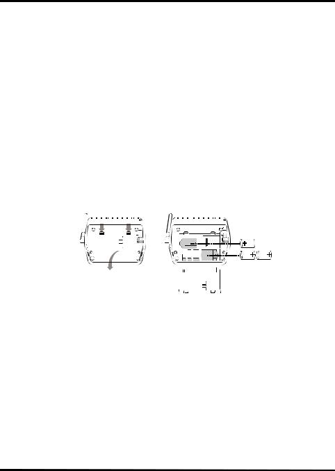
Installing the AC Power Adapter (Optional)
1. Find the power jack located on the left side of the console case.
2. Insert the power adapter plug into the console power jack, then plug the other end of the adapter into an
appropriate power outlet. 3. Check to make sure the console runs through a brief
self-test procedure successfully. See “Installing Batteries” on page 3 for information on the self-test
|
procedure. |
Plugging in the AC adapter |
|
|
|
Note: |
When using an AC power adapter, be sure to use the power adapter supplied with your |
|
|
Vantage Vue console. Your console may be damaged by connecting the wrong power |
|
|
adapter. You must use AC power when using WeatherLinkIP. |
|
|
|
|
Console Location
Place the console in a location where the keyboard is easily accessible and the display is easy to read. For more accurate readings, follow these suggestions.
•Avoid placing the console in direct sunlight. This may cause erroneous inside temperature and humidity readings and may damage the unit.
•Avoid placing the console near radiators or heating/air conditioning ducts.
•If you are mounting the console on a wall, choose an interior wall. Avoid exterior walls that tend to heat up or cool down depending on the weather.
•Avoid positioning a wireless console near large metallic appliances such as refrigerators, televisions, heaters, or air conditioners.
•The console antenna does not rotate in a complete circle. Avoid forcing the console antenna when rotating it.
•Be aware of possible interference from cordless phones or other devices. To prevent interference, maintain a distance of 10 feet (3 meters) between the Vantage Vue console and a cordless phone (handset and base).
4
Console Location
Table & Shelf Placement
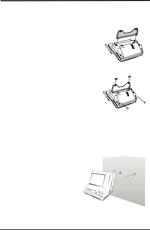
The console comes with a kickstand so that the console can be displayed on any flat surface. To install the kickstand:
1. Locate the two keyholes on the back of the console. 2. Place the two round tabs on the kickstand into the to keyholes and slide the kickstand up into place.
Securing the kickstand
3. Install the two round rubber feet on the bottom of the console.
4. Install the two rubber channel feet on the kickstand.
Installing the rubber feet
Wall Mounting
The console mounts to the wall using two keyholes located on the back of the case (the same two keyholes are used to hold the console kickstand in place) and two #6 x 1'' pan head self-threading screws included in the hardware kit.
To mount the console on a wall:
1.Use a ruler to mark two mounting hole positions on the wall 4 15/16''
|
inches (125 mm) apart. Use the guide |
|
|
|
holes on the kickstand as a template |
|
|
|
for the keyhole spacing. |
|
|
2. |
Use a drill and a 3/32” or 7/64'' (2.4 or |
|
|
|
2.8 mm) drill bit to drill two pilot |
|
|
|
holes for the screws. |
|
|
3. |
Using a screwdriver, drive the two #6 |
|
|
|
x 1'' pan head self-threading screws |
|
|
|
into the wall. Leave at least 1/8'' (3 |
|
|
|
mm) between the wall and the heads |
|
|
|
of the screws. |
Mounting the console on a wall |
|
4. |
Guide the two keyholes on the back |
||
|
of the console over the two screws.
5

Setup Mode
Chapter 3
Using Your Weather Station
The console LCD screen and keyboard provide easy access to your weather information. The LCD display shows current and past weather conditions as well as a forecast of future conditions. The keyboard controls console functions for viewing current and historical weather information, setting and clearing alarms, viewing and/or changing station settings, setting up and viewing graphs, and more.
Console Modes
The Vantage Vue console operates in five different modes:
|
Mode |
Description |
|
|
|
|
|
|
|
|
|
|
Setup |
Use Setup Mode to enter the time, date, and other information required to calculate |
|
|
and display weather data such as latitude, longitude and elevation. See “Setup Mode” |
|
|
|
|
on this page. |
|
|
|
|
|
|
Current |
Use Current Weather Mode to see current weather information, change measurement |
|
|
units, and to set, clear or calibrate weather readings. See “Current Weather Mode” on |
|
|
|
Weather |
|
|
|
page 15. |
|
|
|
|
|
|
|
|
|
|
|
High/Low |
Use High/Low Mode to display the daily, monthly or yearly high and low readings. See |
|
|
“Highs and Lows Mode” on page 30. |
|
|
|
|
|
|
|
|
|
|
|
Alarm |
Use Alarm Mode to set, clear, and review alarm settings for up to 30 different |
|
|
variables/settings. See “Alarm Mode” on page 31. |
|
|
|
|
|
|
|
|
|
|
|
Graph |
Use Graph Mode to display your weather data in the graph section of the console for |
|
|
the current and last 25 time intervals (hours, days, months or even years) in over 50 |
|
|
|
|
different graphs. See “Graph Mode” on page 33. |
|
|
|
|
|
|
|
|
|
Note: |
When the console is first powered, or repowered, the Time & Date screen appears. If |
|
nothing is done for 10 minutes, the screen will time out and go to the Current Weather |
|
screen. (This is true for any setup screen except for the Active Transmitters screen.) |
|
|
Setup Mode
Setup Mode provides access to the station configuration settings that control how the station operates. Setup Mode consists of a series of screens for selecting console and weather station configuration options.
Setup Mode Commands
Setup Mode displays when the console is first powered. This mode can be displayed at any time to change any of the console options.
Use the following commands to enter, exit and navigate Setup Mode:
•Enter Setup Mode by pressing and releasing 2ND and then SETUP.
2ND DONE
SETUP
•Press DONE to move to the next screen in the Setup Mode.
DONE
6
Setup Mode
•Press BAR to display the previous screen in the Setup Mode.
BAR
•Press the < and > keys to move to the different segments and options in
the Setup Mode screens.
• Press the + and - keys to scroll through the different options available.
•Press 2ND and UNITS to change units of measure when applicable.
• Exit Setup Mode by pressing and holding DONE until the Current |
2ND TIME |
Weather screen displays. See “Current Weather Mode” on page 15 |
UNITS |
|
|
for more information. |
|
Screen 1: Time & Date
The very first time you power the console, you should enter the correct date and local time.
To change the time and date:
1.Press the < and > keys to select the hour, minute, month, day or year segments. The selected time or date setting blinks on and off.
2.Press the + and - keys to adjust a value up or down.
To choose between a 12-hour or 24-hour clock, first select either the hour or minute setting, then press 2ND and immediately press UNITS. This toggles the clock setting between the two clock types.
am
YEAR
Screen 1: Time & Date
To choose between a MM/DD or DD.MM
display for the date, first select either the day or month setting, then press 2ND and immediately press UNITS. This switches the console from one date display to the other.
3. Press DONE to move to the next screen.
Note: Whenever the console is repowered after power is off or lost, it will open to this screen. This allows you to enter the correct time if needed. If nothing is done after 10 minutes, the screen will time-out and go to the Current Weather screen.
Screen 2: Time Zone
|
The console is pre-programmed with a |
|
combination of US time zones and the names |
|
of major cities representing time zones around |
|
the world. You can also configure your time |
|
zone using the Universal Time Coordinate |
|
(UTC, also known as Greenwich Mean Time or GMT) offset. |
Note: |
UTC offset measures the difference between the time in any time zone and a standard time, |
|
set by convention as the time at the Royal Observatory in Greenwich, England. Hayward, |
|
California, the home of Davis Instruments, observes Pacific Standard Time. The UTC offset |
|
for Pacific Standard Time is -8:00, or eight hours behind Universal Time (UTC). When |
|
daylight saving time is observed, an hour is added to the offset time automatically. Use this |
|
function in correlation with “Screen 3: Daylight Saving Settings” on page 8. |
7
Setup Mode
1.Press the + and - keys to cycle through time zones.
2.If your time zone is not shown, press 2ND then press the + and - keys to set your UTC offset (UTC offset uses 15 minute increments).
3.Press DONE to select the time zone or UTC offset shown on the screen and move to the next screen.
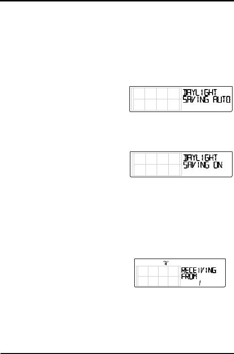
Screen 3: Daylight Saving Settings
In most of the United States and Canada (except Saskatchewan, Arizona, and Hawaii) and Europe you should use the AUTO Daylight Saving setting. The console is pre-programmed to use the correct starting and stopping dates for daylight saving time in these areas, based on the time zone setting in Screen 2: Time Zone.
Weather stations located outside the United States, Canada, and Europe, or in areas that do not observe daylight saving time should use the MANUAL setting.
1.Press the + and - keys to choose Auto or Manual.
2.Press DONE to move to the next screen.
Screen 4: Daylight Saving Status
Use this screen to either verify the correct automatic daylight saving status or to set daylight saving manually.
1.If the daylight saving setting is MANUAL,
press the + and - keys to turn daylight saving time on or off on the appropriate days of the year. This will advance the time by one hour. (Similarly, if you turn daylight saving time off, the time will be set back one hour.)
If you have an AUTO daylight saving setting, the console displays the appropriate setting based on the current time and date.
2.Press DONE to move to the next screen.
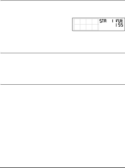
Screen 5: Active Transmitters
Screen 5 displays the message “Receiving from...” and shows the ID number of any transmitters being received by the console. The rest of the screen is blank.
If your ISS uses the factory settings and your
console is receiving the signal, the screen displays “RECEIVING FROM 1.” The antenna icon displays if any station’s signal has been received. The antenna icon will not display if
the console has not received a signal from a station.
If you have installed a Vantage Pro2 ISS or Anemometer Transmitter kit, or if a nearby neighbor has a Davis weather station, or if you are receiving from another console in retransmit mode, its ID number will also be displayed.
8
|
Setup Mode |
|
|
|
|
|
|
|
Note: |
A Vantage Vue or Vantage Pro2 ISS or a Vantage Pro2 Anemometer Transmitter Kit must be |
|
|
powered for the console to recognize it. Refer to the Integrated Sensor Suite Installation |
|
|
Manual or other station manual for more information. It may take several minutes for the |
|
|
console to acquire and display a transmitter ID after power is applied to both units. |
|
1.Make a note of the station number(s) listed on the screen.
2.Press DONE to move to the next screen.
Screen 6: Configuring Transmitter IDs
Setup Screen 6 allows you to change the ISS
transmitter ID and to add or remove optional transmitter stations. The default transmitter ID setting is “1 VUE
ISS” (refers to a Vantage Vue ISS), which is
appropriate for most installations. If you are using only the Vantage Vue ISS with ID 1 press DONE to move to the next screen.
Note: |
Typically, you can use the default transmitter ID setting of 1 unless a nearby neighbor has a |
|
Vantage Pro2 or Vantage Vue station that uses transmitter ID 1. |
If you wish to change this default transmitter ID:
1.Press the < and > keys to select a transmitter ID.
When you select a transmitter ID (1 - 8), the ID number is displayed on the screen as well as its current configuration (OFF, VUE ISS, VP2 ISS or WIND).
2.Press the + or - keys to toggle console reception of signals from transmitters using that ID on and off.
Note: |
Make sure any unused ID numbers are set to OFF. |
To change the station type for the transmitter ID:
1.Press GRAPH to change the type of station assigned from VUE ISS to VP2 ISS or WIND.
•VUE ISS - Refers to the Vantage Vue ISS (whether direct transmission or retransmission from another console).
•VP2 ISS - Refers to the Vantage Pro2 ISS (whether direct transmission or retransmission from another console).
•WIND - Refers to an optional Anemometer Transmitter Kit (direct transmission only).
2.Press DONE to move to the next screen.
Note: |
This screen contains functionality for enabling repeaters. If the word “Repeater” displays in |
|
the right corner of the screen and you are not using repeaters as part of your network, see |
|
“Clearing Repeater ID” on page 51. If you are using repeaters as part of your network see |
|
“Wireless Repeater Configuration” (Appendix C) on page 51. |
|
|
9
Setup Mode
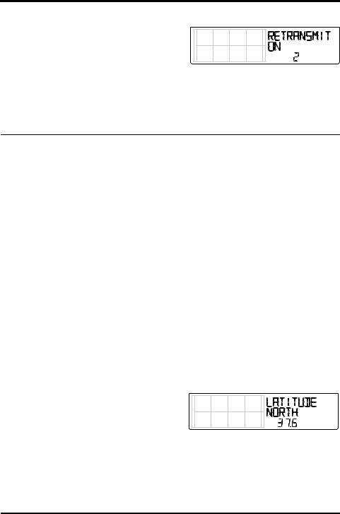
Screen 7: Retransmit
The console can take data it receives from all
three station types and retransmit it to other Vantage Vue or Vantage Pro2 consoles using
the retransmit feature. By toggling the feature on, the console becomes another transmitter
that requires its own unique ID to transmit the data received from the ISS.
1.Press the + or - key to turn the retransmit function on and off. The first available transmitter ID not assigned to a station in Screen 6: Configuring Transmitter IDs will be assigned to the console.
Note: |
Make sure no other wireless Davis weather station is transmitting on the same ID. |
The Vantage Vue console can only retransmit data from either a Vantage Vue ISS or console; or a Vantage Pro2 ISS or console. Data from other stations will not retransmit. When retransmit has already been enabled, pressing the < or > keys changes the transmitter ID used for retransmit.
2.Use the > key to scroll through the list of available transmitter IDs and select the ID for your console.
3.Press DONE to move to the next screen.
Note: |
Make a note of the ID selected for retransmit and the transmitter type (ISS or VP2) the |
|
console is retransmitting. Make sure the console that is receiving the retransmitted data is |
|
configured to the correct transmitter type. See “Screen 6: Configuring Transmitter IDs” on |
|
page 9 for more information. |
|
|
Screens 8 and 9: Latitude and Longitude
The console uses latitude and longitude to determine your location, allowing it to adjust the forecast and calculate the times for sunset and sunrise.
•Latitude measures distance north or south of the equator.
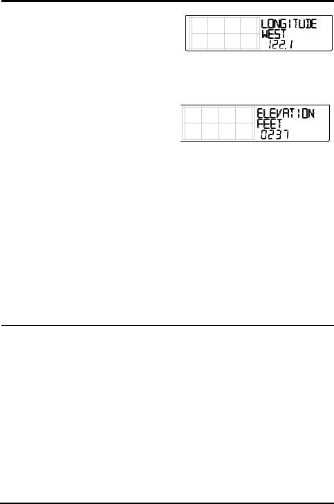
•Longitude measures distance east or west of the Prime Meridian, an imaginary line running north and south through Greenwich, England.
If you do not know your latitude and longitude, there are several ways to find out. Many atlases and maps include latitude and longitude lines. You can also talk to the reference department of your local library, call your local airport, or search on the Internet. An easy way to find your latitude and longitude is to download Google Earth (http://earth.google.com). The more accurate you are, the better; however, a reasonable estimate will work, too.
1. Press the < and > keys to move between
fields. 2. Press the + and - keys to change the
settings up or down.
3.Press 2ND and then UNITS to select between SOUTH or NORTH.
4.Press DONE to move to the Longitude screen.
10
Setup Mode
1. Press the < and > keys to move between
fields. 2. Press the + and - keys to change the
settings up or down. 3. To select EAST or WEST, press 2ND, then
UNITS.
4. Press DONE to move to the next screen.
Screen 10: Elevation
Your station’s elevation is used in determining
your barometric pressure. Meteorologists standardize barometric pressure data to sea
level so that surface readings are comparable, whether they are taken on a mountainside or by the ocean. To use this same standardization
and ensure consistent readings, enter your elevation in this screen.
If you do not know your elevation, there are several ways to find out. Many atlases and almanacs include elevation for cities and towns. You can also check with the reference department of your local library, or use Google Maps (in “terrain” view).
The more accurate you are, the better; but a reasonable estimate works too.
1.Press the < and > keys to move from one value to another.
2.Press the + and - keys to adjust a numeral up or down.
3.To switch between feet and meters, press 2ND then press UNITS.
4.If your location is below sea level, such as in Death Valley or the Salton Sea, first enter the elevation as a positive number. Select the “0” immediately to the left of the left-most non-
zero digit (the second zero from the left in 0026, for example, or the first zero from the left in 0207) and press and hold the + or - key until it cycles from 0 to 9 and then -.
Note: |
You can only set the elevation to negative after you have entered a non-zero digit and when |
|
the zero in the position immediately to the left of the left-most non-zero digit has been |
|
selected. If you need to enter an elevation below -999 feet, select meters and enter the |
|
converted number (multiply your elevation in feet by 0.3048). |
5. Press DONE to move to the next screen.
11
Setup Mode
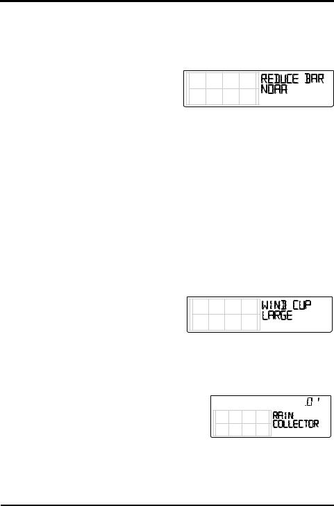
Screen 11: Barometric Reduction Setting
The Barometric Reduction Setting screen indicates the method by which barometric pressure is to be determined and calculated. The factory default is NOAA, but in this screen you may select a different method.
To change the barometric reduction setting: 1. Press + or - to change the barometer
reduction setting type:
•NOAA (Default Setting) — The barometer is reduced to sea level using a
technique that factors in the humidity and temperature of the column of air.
•ALT SETTING (Altimeter Setting) — The barometer is reduced to sea level using a “standard” column of air, often referred to as a “standard atmosphere.”
•NONE — Reports a raw barometric pressure reading unadjusted for elevation/altitude.
2.Press DONE to move to the next screen.
Note: |
See “Calibrating Barometric Pressure” on page 28 to learn how to fine-tune your barometric |
|
pressure to a local source. |
|
|
Screen 12: Wind Cup Type (Optional)
The Wind Cup Type screen displays if you selected VP2 or WIND in Screen 6 of the Setup Mode. This screen does not display if you have selected a Vantage Vue ISS. See “Screen 6: Configuring Transmitter IDs” on page 9 for more information.
The Wind Cup Type screen contains three options: LARGE, SMALL, or OTHER. In most Vantage Pro2 anemometer or ISS Installations, LARGE is the cup type that is shipped with all Vantage Pro2 anemometers. See the Vantage Pro2 Console Manual for more information. To change the wind cup type:
1. Press the + and - keys to scroll through the three wind cup options.
2.Press DONE to use the selected setting and move to the next screen.
Note: |
Do not change the wind cup type from LARGE if you are using the wind cups that were |
|
shipped with your system. |
|
|
Screen 13: Rain Collector
The tipping spoon in the Vantage Vue rain collector has been calibrated at the factory to measure either 0.01'' or 0.2mm of rain with each tip depending on the model. This screen is used at the factory for this calibration. The typical user will not need to change it and can skip this screen.
 in
in
Note: |
This screen will not change the units on your display. To change the units on your display |
|
from inches to mm, or vice versa, see “Selecting Units of Measure” on page 26. |
|
|
12

Setup Mode
Screen 14: Rain Season
Because rainy seasons begin and end at different times in different parts of the world, you must specify the month you wish your yearly rain data to begin. January 1st is the default setting.
The date the rain season begins affects yearly rain rate highs and lows as well as the yearly rain totals.
1.Press the + and - keys to select the month for the start of the rainy season.
2.Press DONE to move to the next screen.
Note: |
This setting determines when the yearly rain total is reset to zero. Davis Instruments |
|
recommends a January rain season setting (the default), unless you reside on the west |
|
coast of the United States, the Mediterranean Coast, or experience dry winters in the |
|
southern hemisphere. If so, change the rain season setting to July 1st. If you are performing |
|
hydrology studies in any of these climates in the Northern Hemisphere, change the rain |
|
season setting to October 1st. |
Screens 15 and 16: Cooling and Heating Degree Day Base
The Cooling and Heating Degree Day Base screens let you determine the temperature base that is used to calculate the number of cooling or heating degree days. A cooling degree day is used to determine the amount of energy or fuel used to keep a structure like your home or business cool. A heating degree day is used to determine the amount of energy or fuel used to keep a structure like your home or business warm.
One cooling degree/day is the amount of cooling required to keep a structure cool when the outside temperature remains 1°F above the 65°F threshold for 24 hours. One cooling degree/ day is also the amount of cooling required when the temperature remains 24°F above the 65°F threshold for one hour.
One heating degree/day is the amount of heat required to keep a structure warm when the outside temperature remains 1°F below the 65°F threshold for 24 hours. One heating degree/ day is also the amount of heat required when the temperature remains 24°F below the 65°F threshold for one hour.
The cooling and heating degree days (similar to growing degree days and chilling requirement in agriculture) are used for agricultural purposes, as well as for energy use analysis. Our optional WeatherLink software (#6510USB, 6510SER, 6555) calculates degree day totals. Our optional Agricultural/Turf Management Software Module (#6511) adds the special reporting features to the WeatherLink software that include evapotranspiration and chilling requirement.
The Cooling and Heating Degree Day Bases are used to determine the Cooling Degree Day Daily Total and Heating Degree Day Daily Total, which display as part of the Weather Center when the outside temperature variable is selected. See “Inside and Outside Temperature” on page 18 for more information.
A base setting for both the Cooling and Heating Degree Day temperature is not set at the factory, allowing you to choose. A base of 65°F (15°C in Europe) is suitable for most applications.
13
Loading...