


Vantage Pro2 Console
Table of contents
 Loading...
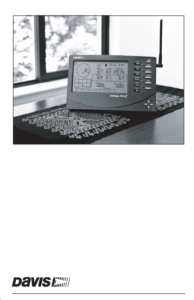
™
Vantage Pro2
Console Manual
For Vantage Pro2 & Vantage Pro2 Plus Weather Stations
Davis Instruments, 3465 Diablo Avenue, Hayward, CA 94545-2778 U.S.A. • 510-732-9229 • www.davisnet.com
™™
®
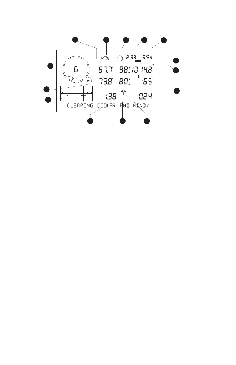
Vantage Pro2 Console Display Features
WIND
N
NW
1
WE
MPH
SW
Last 24 hrshrEvery 1
14
13
Vertical Scale: X10
32
NE
GRAPH
TEMP OUT
TEMP IN
SE
S
DAILY
F
F
in
STATION NO.1
HUM OUT
HUM IN
4
pm
2nd
BAROMETER
RAIN RATE
CHILL
5
hPa
F
in/hr
6
7
8
9
12
11
10
Display Features
1. Compass Rose
2. Graph & Hi/Low Mode Settings
3. Forecast Icons
4. Moon Phase Indicator
5. Time/Sunrise Time
6. Date/Sunset Date
7. 2ND Button Indicator
FCC Part 15 Class B Registration Warning
This equipment has been tested and found to comply with the limits for a Class B digital device, pursuant to Part
15 of the FCC Rules. These limits are designed to provide reasonable protection against harmful interference in a
residential installation. This equipment generates, uses, and can radiate radio frequency energy and, if not
installed and used in accordance with the instructions, may cause harmful interference to radio communications.
However, there is no guarantee that interference will not occur in a particular installation. If this equipment does
cause harmful interference to radio or television reception, which can be determined by turning the equipment on
and off, the user is encouraged to try to correct the interference by one or more of the following measures:
• Reorient or relocate the receiving antenna.
• Increase the separation between the equipment and receiver.
• Connect the equipment into an outlet on a circuit different from that to which the receiver is connected.
• Consult the dealer or an experienced radio/TV technician for help.
Changes or modification not expressly approved in writing by Davis Instruments may void the warranty and void
the user's authority to operate this equipment.
FCC ID: IR2DWW6312
IC: 378810-6312
EC EMC Compliance
This product complies with the essential protection requirements of the EC EMC Directive 2004/108/EC; Low Voltage Directive 2006/95/EC; and Eco-Design Directive 2005/32EC > .05 watt no-load adaptor.
Vantage Pro2 Console Manual
Document Part Number: 07395.234 Rev. K, 1/12/12
For Vantage Pro2 Consoles # 6312 & 6312C
And Vantage Pro2 Weather Stations # 6152, 6152C, 6153, 6162, 6162C, 6163
®
Vantage Pro
, Vantage Pro2™, and WeatherLink® are trademarks of Davis Instruments Corp.,
Hayward, CA. Windows® is a trademark of Microsoft Corporation in the US and other countries.
Macintosh® is a trademark of Apple, Inc. in the US and other countries.
© Davis Instruments Corp. 2012 All rights reserved.
Information in this document subject to change without notice.
Davis Instruments Quality Management System is ISO 9001 certified.
8. Barometric Trend Arrow
9. Graph Icon
10. Current Rain Icon
11. Station Number Indicator
12. Weather Ticker
13. Graph Field
14. Alarm Icon

Table of Contents
Welcome to Vantage Pro2TM ...........................................................................................1
Console Features ....................................................................................................... 1
Vantage Pro2 Options ............................................................................................... 2
Installing the Console ......................................................................................................4
Powering the Console ............................................................................................... 4
Installing the AC Power Adapter .............................................................................. 4
Installing Batteries .................................................................................................... 5
Connecting Cabled Stations ...................................................................................... 5
Console Location ...................................................................................................... 6
Using Your Weather Station ............................................................................................9
Setup Mode ............................................................................................................... 9
Current Weather Mode ........................................................................................... 18
Selecting Units of Measure ..................................................................................... 18
Displaying the Forecast ..........................................................................................24
Displaying Time & Date or Sunrise & Sunset ....................................................... 24
Calibrating, Setting, and Clearing Variables .......................................................... 25
Highs and Lows Mode ............................................................................................ 27
Alarm Mode ............................................................................................................ 28
Graph Mode ............................................................................................................ 31
Troubleshooting and Maintenance .................................................................................34
Vantage Pro2 Troubleshooting Guide .................................................................... 34
Console Diagnostic Mode ...................................................................................... 36
Console Maintenance ............................................................................................. 40
One Year Limited Warranty ................................................................................... 40
Appendix A Weather Data .............................................................................................41
Appendix B Specifications .............................................................................................47
Console Specifications ........................................................................................... 47
Wireless Communication Specifications ................................................................ 47
Console Data Display Specifications ..................................................................... 48
Weather Data Specifications .................................................................................. 49
Appendix C Wireless Repeater Configuration ...............................................................51
Vantage Pro2 Console Icons ..........................................................................................53
i

Chapter 1
Welcome to Vantage Pro2
Welcome to your Vantage Pro2 Weather Station console. The console displays and
records your station’s weather data, provides graph and alarm functions, and interfaces
to a computer using our optional WeatherLink
Vantage Pro2 stations are available in two basic versions: cabled and wireless. A
cabled Vantage Pro2 station transmits outside sensor data from the Integrated Sensor
Suite (ISS) to the console using a straight-through four-conductor cable. A wireless
Vantage Pro2 station transmits outside sensor data from the ISS to the console via a
low-power radio.
Note: Wireless consoles can also collect data from optional Vantage Pro2 sensors or a
Davis Vantage Vue ISS, and can also retransmit data to other Vantage Pro2 or Vantage Vue consoles or a Davis Weather Envoy. You can have an unlimited number of
consoles - one in each room!
The Vantage Pro2 Quick Reference Guide included with your station provides an easy
to use reference for most console functions.
®
TM
software.
Console Features
Keyboard & Display
The keyboard lets you view current and historical data, set and clear alarms, change
station models, enter calibration numbers, set up and view graphs, select sensors, and
read the forecast. The keyboard consists of 12 command keys located next to the screen
display and four navigation keys located below the command keys.
A weather variable or console command is printed on each command key.
Just press a key to select the variable or function printed on that key.
Each command key also has a secondary function which is printed above
the key on the console case. To select the secondary function, press and
release 2ND (on the front of the console, upper right corner) and then
immediately press the key for that function.
After pressing 2ND, the 2ND icon displays above the barometer reading on the screen
for three seconds. All secondary key functions are enabled during this time. Keys
resume normal operation after the icon disappears.
The+ and - navigation keys, along with < and > navigation keys are used
to select command options, adjust values, and to provide additional functions when used in combination with a command key.
CHILL
WIND
2
+
<
ND
>
-
1
Console Modes
The console operates in five basic modes: Setup, Current Weather, Highs and
Lows, Alarm, and Graph. Each mode lets you access a different set of console
functions or display a different aspect of your weather data.
Vantage Pro2 Options
Optional Sensors & Transmitting Stations
Vantage Pro2 stations are extremely flexible. Use the following optional sensors
and wireless stations to enhance the weather monitoring capabilities of your Vantage Pro2. See our web site for complete details:
www.davisnet.com.
Optional Sensor and Stations Description
Anemometer/Sensor Transmitter
Kit (#6332)
Vantage Connect (#6620)
Wireless Leaf & Soil Moisture/
Temperature Station (#6345)
Wireless Temperature Station
(#6372)
Wireless Temperature/Humidity
Station (#6382)
Solar Radiation Sensor (#6450)
Ultraviolet (UV) Radiation Sensor
(#6490)
Vantage Pro2 Options
Provides more flexible anemometer placement for wireless
stations. With Envoy8X, allows additional solar radiation,
UV, temperature, rain or 3rd party (reporting 0-3 volt)
sensors.
Transmits data from remote ISS to WeatherLink.com via
cellular connection.
Measures and transmits leaf wetness, soil moisture and
temperature data. Also for use with GLOBE.
Measures and transmits temperature data.
Measures and transmits air temperature and humidity
data.
Measures solar radiation. Required for calculating
evapotranspiration (ET). Available for cabled and wireless
stations. Requires Sensor Mounting Shelf (#6673).
Measures UV radiation. Required for calculating the UV
dose. Available for Cabled and Wireless stations. Requires
Sensor Mounting Shelf (#6673).
Note: Optional wireless stations can only be used with Wireless Vantage Pro2 Stations.
Optional WeatherLink® Software
The WeatherLink software and data logger connect your Vantage Pro2 station
directly to a computer, providing enhanced weather monitoring capabilities, a continuous preserved data record, and powerful Internet features. The WeatherLink
data logger fits neatly on the console and stores weather data even when the com-
puter is turned off.
WeatherLink Option Description
WeatherLink for Windows, USB
connection (#6510USB)
WeatherLink for Windows, serial
connection (#6510SER)
WeatherLink for Macintosh OS
X, USB connection (#6520)
Includes WeatherLink software and USB data logger. Allows you
to save and view your weather data on your PC.
Includes WeatherLink software and serial data logger. Allows
you to save and view your weather data on your PC.
Includes WeatherLink software and USB data logger. Allows you
to save and view your weather data on your Mac.
2
Vantage Pro2 Options
WeatherLink Option Description
Requires a broadband router with available Ethernet port. Allows
WeatherLinkIP for Windows XP/
Vista/7 (#6555)
WeatherLink for APRS,
Windows version, with
streaming data logger, serial
connection (#6540)
WeatherLink for Alarm Output,
for Windows, with streaming
data logger, serial connection
(#6544)
WeatherLink for Emergency
Response teams, Windows
version, with streaming data
logger, serial connection
(#6550)
WeatherLink for Irrigation
Control, Windows version, with
streaming data logger, serial
connection
(#6560)
you to post your weather data directly to your personal web page
on WeatherLink.com without a PC. Among other features, allows
you to receive e-mail alerts of current weather conditions or
simple alarm conditions.
Includes WeatherLink software and streaming serial data logger.
Allows real-time display of current weather conditions for use
with APRS (Automatic Position Reporting System), for HAM
radio users.
Includes WeatherLink software and streaming serial data logger.
Gives you the ability to control external devices based on various
combinations of weather trends and events.
Includes WeatherLink software and streaming serial data logger.
Allows real-time display of current weather conditions for use by
emergency response teams.
Includes WeatherLink software and streaming serial data logger.
Allows intelligent and efficient control of popular automated
irrigation systems using weather data.
Optional Accessories
Accessories are available from your dealer or may be ordered directly from Davis
Instruments.
Envoys: Wireless Weather Envoy (#6316,) Envoy8X (#6318)
Performs many of the same functions as a Vantage Pro2 console, but without a display.
Use an Envoy to interface your wireless station to a computer, freeing the display for
use elsewhere. Weather Envoy can receive the same number and combinations of stations as a Vantage Pro2 console; Envoy8X can receive up to 8 stations in any combination and create a large database.
Sensor Mounting Shelf (#6673)
Required for mounting the optional Solar Radiation and/or UV sensors. The mounting
shelf attaches to the base of the rain collector on the ISS.
Additional Vantage Pro2 (#6312) or Vantage Vue Console (#6351)
Enjoy weather information in several rooms.
USB-to-Serial (DB-9) Cable (#8434)
Allows the Serial version of WeatherLink (#6510SER, 6540, 6544, 6550, 6560) to connect to a USB port on your computer.
Telephone Modem Adapter (#6533)
Required when connecting station to an external phone modem.
Extension Cables (#7876)
Allows you to place the Cabled Vantage Pro2 ISS further away from the console using
the extension cable provided by Davis Instruments. Maximum cable length is 1000’
feet (300 m).
• #7876-040 Cable, 40’ (12 m)
• #7876-100 Cable, 100’ (30 m)
• #7876-200 Cable, 200’ (61 m)
3
Chapter 2
Installing the Console
The Vantage Pro2 console is designed to give extremely accurate readings. As with any
precision instrument, use care in its assembly and handling. Although installing the
console is relatively simple, following the steps outlined in this chapter and assembling
the Vantage Pro2 correctly from the start will help ensure that you enjoy all of its features with a minimum of time and effort.
Powering the Console
Cabled Vantage Pro2 Stations
Cabled Vantage Pro2 consoles supply power to the Integrated Sensor Suite (ISS)
through the console cable. Because of the added power consumption of the ISS, the
cabled console requires an AC power adapter used as the main power supply. The console batteries provide backup power for up to four to six weeks.
Wireless Vantage Pro2 Stations
Wireless Vantage Pro2 consoles do not require the use of an AC adapter. You may use
the included adapter if you wish, but the three C-cell batteries should power a wireless
console for up to nine months.
Note: When using an AC Power adapter, be sure to use the power adapter supplied with
your Vantage Pro2 Console. Your console may be damaged by connecting the
wrong power adapter. The console does not recharge the batteries. Because of this,
and because NiCad batteries do not power the console as long as alkaline batteries,
use alkaline batteries in the console.
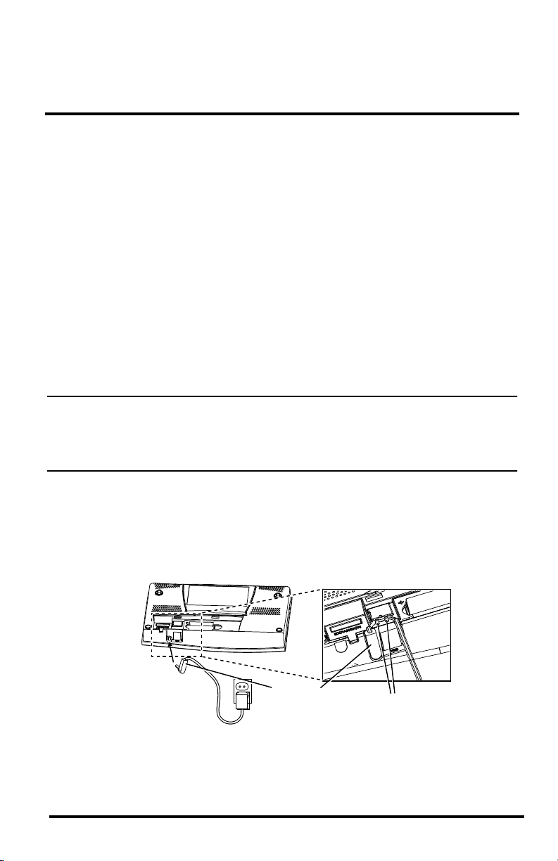
Installing the AC Power Adapter
1. Remove the battery cover located on the back of the console by pressing down on
the two latches at the top of the cover.
2. Find the power jack located on the bottom of the console case.
Power Plug
3. Insert the power adapter plug into the console power jack, then plug the other end of
the adapter into an appropriate power outlet.
Wrap Cord Around Pins
4
Installing Batteries
4. Check to make sure the console runs through a brief self-test procedure successfully.
On power up, the console displays all the LCD segments and beeps twice. A message displays in the ticker banner at the bottom of the console, followed by the first
screen that displays during Setup Mode. Press and hold DONE to skip the message
and enter into Setup Mode.
Setup Mode guides you through steps required to configure the station. See “Setup
Mode” on page 9 for more information.
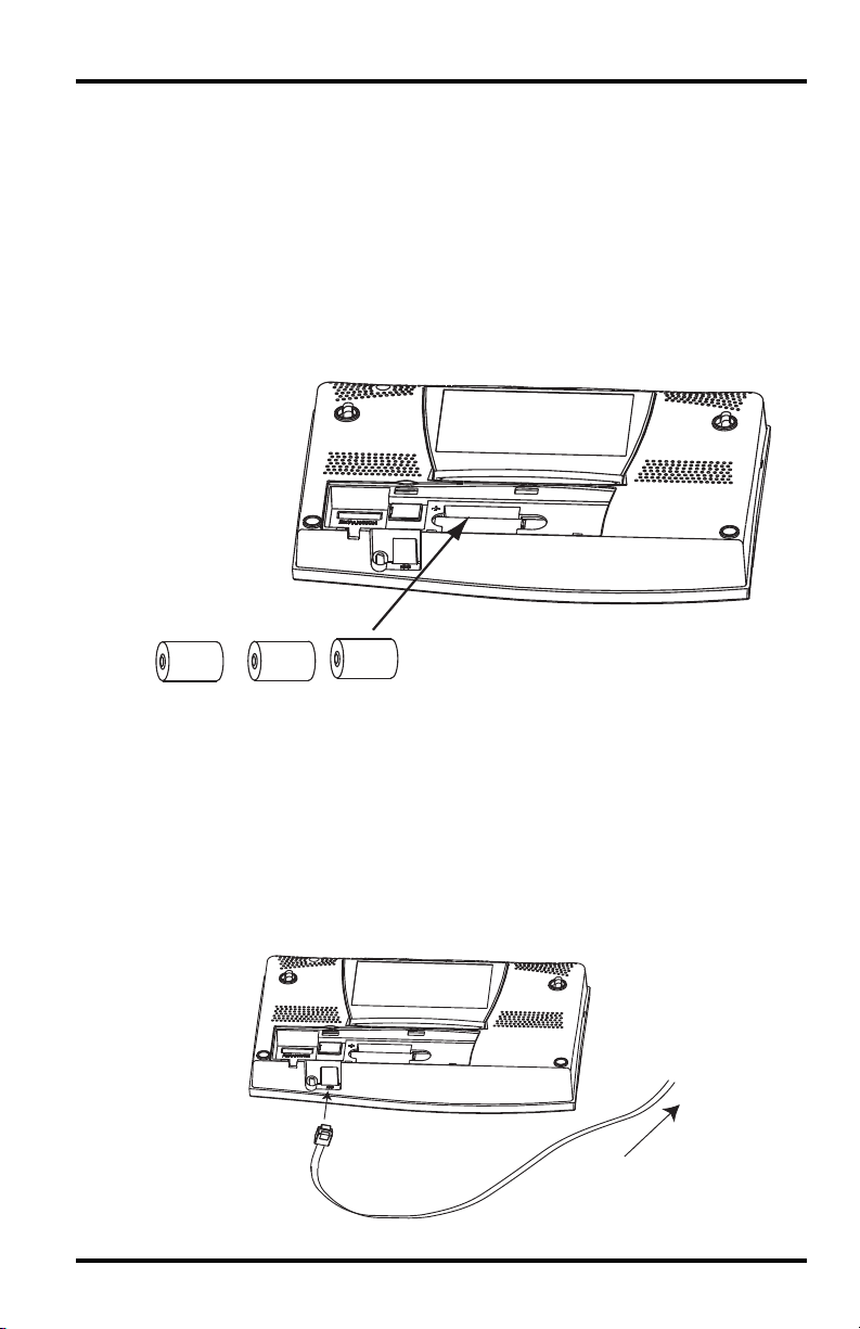
Installing Batteries
1. Remove the battery cover located on the back of the console by pressing down on
the two latches at the top of the cover.
Battery
Battery
Battery
2. Insert three C batteries into the battery channel, negative (or flat) terminal first.
3. Replace the battery cover.
Connecting Cabled Stations
Cabled Vantage Pro2 stations come with 100 feet (30m) of cable. This cable is used for
connecting the console to the ISS. Maximum cable length from ISS to the console
using Davis Instruments cables is 1000 feet. To connect the console to the ISS:
1. Firmly insert the console end of the straight-through four-conductor wire into the
console receptacle marked “ISS” until it clicks into place. Do not force the
connector into the receptacle.
To ISS
5

Console Location
2. Ensure that the ISS cable is not twisted through the access port.
Note: The ISS must be assembled and connected to the console so that it is receiving
power before the console connection can be tested.
Once the console and ISS are both powered up, cable connection should be tested and
established.
Once the console is powered, it automatically enters Setup Mode. You can step through
the Setup Mode options, or exit the Setup Mode to test the connection and sensor readings in Current Weather Mode. See “Setup Mode” on page 9 for Setup Mode options.
See “Current Weather Mode” on page 18 for viewing and verifying current weather
data coming from the cabled console.
To verify that the console is receiving data from the ISS through the console connection, see “Cabled ISS Assembly” in the Integrated Sensor Suite Installation Manual.
Console Location
Place the console in a location where the keyboard is easily accessible and the display
is easy to read. For more accurate readings:
• Avoid placing the console in direct sunlight. This may cause erroneous inside tem-
perature and humidity readings and may damage the unit.
• Avoid placing the console near radiators or heating/air conditioning ducts.
• If you are mounting the console on a wall, choose an interior wall. Avoid exterior
walls that tend to heat up or cool down depending on the weather.
• If you have a wireless console, be aware of possible interference from cordless
phones or other devices. To prevent interference, maintain a distance of 10 feet
between the Vantage Pro2 console and a cordless phone (handset and base).
• Avoid positioning a wireless console near large metallic appliances such as refrig-
erators, televisions, heaters, or air conditioners.
• The console antenna does not rotate in a complete circle. Avoid forcing the console
antenna when rotating it.
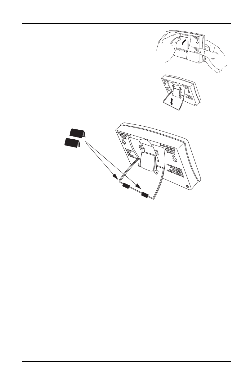
Table & Shelf Placement
The console kickstand can be set to three different angles allowing five different display angles.
1. Install the two round rubber feet on the bottom of the console. The rubber feet help
prevent damage to furniture and surfaces.
6
Console Location
2. Lean the kickstand out by pulling on its top
edge.
You’ll see the indentation for your finger at the
top edge of the console.
3. Slide the catch to rest the kickstand in the appropriate angle.
Choose low angles for display on a coffee table
or other low area. Choose higher angles for display on a desk or shelf.
4. Install the two rubber channel feet on the kickstand.
If necessary, pull up on the stand to close it. It will be a little tight, so it’s okay to push
hard enough to get it to slide.
7
Console Location
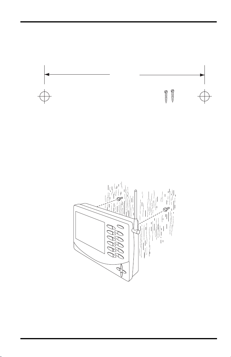
Wall Mounting
The console mounts to the wall using two keyholes located on the back of the case.
To mount the console on a wall:
1. Use a ruler to mark two mounting hole positions on the wall 8 inches (203 mm)
apart.
8" (203mm)
Drill two 3/32" or 7/64" (2.4 to 2.8mm) holes
8" (203mm) apart for the #6 x 1" mounting screws.
This is a representation for the mounting hole positions. This template is not true to size.
If installing a cabled Vantage Pro2 console with sensor cable running inside the
wall, mount the console over an empty switch box.
2. Use a drill and a 3/32 or 7/64''(2.5 mm) drill bit to drill two pilot holes for the
screws.
3. Using a screwdriver, drive the two #6 x 1'' pan head self-threading screws into the
wall. Leave at least 1/8'' (3 mm) between the wall and the heads of the screws.
4. If the kickstand has been pulled out from the case, push it back into its upright and
locked position.
5. Guide the two keyholes on the back of the console over the two screws.
8
Chapter 3
Using Your Weather Station
The console LCD screen and keyboard provide easy access to your weather information. The large LCD display shows current and past environmental conditions as well
as a forecast of future conditions. The keyboard controls console functions for viewing
current and historical weather information, setting and clearing alarms, changing stations types, viewing and/or changing station settings, setting up and viewing graphs,
selecting sensors, getting the forecast, and so on.
Console Modes
The Vantage Pro2 console operates in five different modes:
Mode Description
Setup
Current Weather
High/Low High/Low Mode displays the daily, monthly or yearly high and low readings.
Alarm Alarm Mode allows you to set, clear, and review alarm settings.
Graph Graph Mode displays your weather data using over 100 different graphs.
Setup Mode
Setup Mode provides access to the station configuration settings that control how the
station operates. Setup Mode consists of a series of screens for selecting console and
weather station options. The screens that display in Setup Mode vary depending on the
weather station type (cabled or wireless), or if the console has a WeatherLink connection already established. (See the WeatherLink Getting Started Guide for more information on connecting your console to your computer.)
Setup Mode Commands
Setup Mode displays when the console is first powered. This mode can be displayed at
any time to change any of the console/weather station options. Use the following commands to enter, exit and navigate Setup Mode:
• Enter Setup Mode by pressing DONE and the - key at the same time.
Use Setup Mode to enter the time, date, and other information required to
calculate and display weather data.
Use Current Weather Mode to read the current weather information,
change measurement units, and to set, clear or calibrate weather readings.
Note: The console automatically enters Setup Mode when first powered.
• Press DONE to move to the next screen in the Setup Mode.
• Press BAR to display the previous screen in the Setup Mode.
• Exit Setup Mode by pressing and holding DONE until the Current Weather screen
displays.
9
Setup Mode
Screen 1: Active Transmitters
Screen 1 displays the message “Receiving from...” and shows the transmitters being
received by the console. In addition, an “X” blinks in the lower right-hand corner of the
screen every time the console receives a data packet from a station. The rest of the LCD
screen is blank.
If you have a cabled station, or if your wireless ISS uses the factory settings and you are
receiving the signal, the screen displays “Receiving from station No. 1.” Any optional
stations that have been installed should also display.
STATION NO.1
Screen 1: Active Transmitters
Note: An ISS or optional station must be powered for the console to recognize it. Refer to
the Integrated Sensor Suite Installation Manual or optional station installation instruc-
tions for more information. It make take several minutes for the console to acquire
and display a Transmitter ID.
4
1. Make a note of the station number(s) listed on the screen.
Note: If a Vantage Pro2 or Vantage Vue ISS has been installed in your area, its ID number
may also be displayed.
2. Press DONE to move to the next screen.
The console can receive signals from up to eight transmitters total, but there is a limit
on the number of certain types of transmitters. The table below lists the maximum number of stations allowable for a receiver:
Station Type Maximum Number
Integrated Sensor Suite (ISS)
Anemometer Transmitter Kit (replaces
ISS anemometer)
Leaf & Soil Moisture/Temperature Station
Temperature Station
Temperature/Humidity Station
*Two are allowable only if both stations are only partially populated. For example, A network can either
have both a Leaf Wetness/Temperature station and a Soil Moisture/Temperature station, or it can
have one combined Leaf Wetness and Soil Moisture/Temperature station.
Note: Listening to more than one transmitter may reduce battery life significantly.
Maximum Number of Transmitters in a Network with One Receiver
1
1
2*
8
8
Screen 2: Configuring Transmitter IDs — Wireless Only
(If you have a cabled station, press DONE and continue on to “Screen 4: Time & Date”
on page 12.)
Setup screen 2 allows you to change the ISS transmitter ID and to add or remove
optional transmitter stations. The default transmitter ID setting is “1” (ISS), which
works fine for most installations.
10
Setup Mode
1
Screen 2: Transmitter ID configuration
If you have a cabled station, or if you have a wireless station and are using the
default transmitter ID setting, press DONE to move to the next screen.
Note: Typically, you can use the default transmitter ID setting of 1 unless you are installing
one of the optional transmitter stations. However, if you are having trouble receiving
your station, there may be another ISS with ID 1 operating nearby. Try changing the
ID of both the console and ISS to another ID number.
3. Press the < and > keys to select the transmitter ID.
When you select a transmitter ID, the ID number is displayed on the screen as well
as the current configuration.
4. Press the + and - keys to toggle console reception of signals from transmitters using
that ID on and off.
5. Press GRAPH to change the type of station assigned to each transmitter. Scroll
through the station types - ISS, TEMP, HUM, TEMP HUM, WIND, RAIN, LEAF,
SOIL, and LEAF/SOIL - until the correct type appears.
6. Press DONE to move to the next screen.
Note: This screen contains functionality for enabling repeaters. If the word “Repeater” dis-
plays in the right corner of the screen and you are not using repeaters as part of your
network, see “Clearing Repeater ID” on page 52. If you are using repeaters as part of
your network see “Wireless Repeater Configuration” (Appendix C) on page 51 for
configuring repeaters on the console.
Screen 3: Retransmit — Wireless Only
If you have a cabled station, press DONE and go to “Screen 4: Time & Date” on
page 12.
The console can retransmit the data it receives from the ISS to other Vantage Pro2 or
Vantage Vue consoles using the retransmit feature. By toggling the feature on, the console becomes another transmitter that requires its own unique ID to transmit the data
received from the ISS.
2
Screen 3: Retransmit
1. Press the + or - keys to turn the retransmit function on and off. The first available
transmitter ID not used by the ISS or any optional sensor is automatically assigned.
Data from the ISS is the only data that can be retransmitted by the console.
When retransmit has already been enabled, pressing the < and > keys changes the
Transmitter ID used for retransmit.
2. Use the > key to scroll through the list of available transmitter IDs and select the ID
for your console.
3. Press DONE to move to the next screen.
11
Setup Mode
Note: Make a note of the ID selected for retransmit. The console that receives the data
from the console you have selected to retransmit should be configured to receive the
transmitter ID you selected. See “Screen 2: Configuring Transmitter IDs — Wireless
Only” on page 10 for more information.
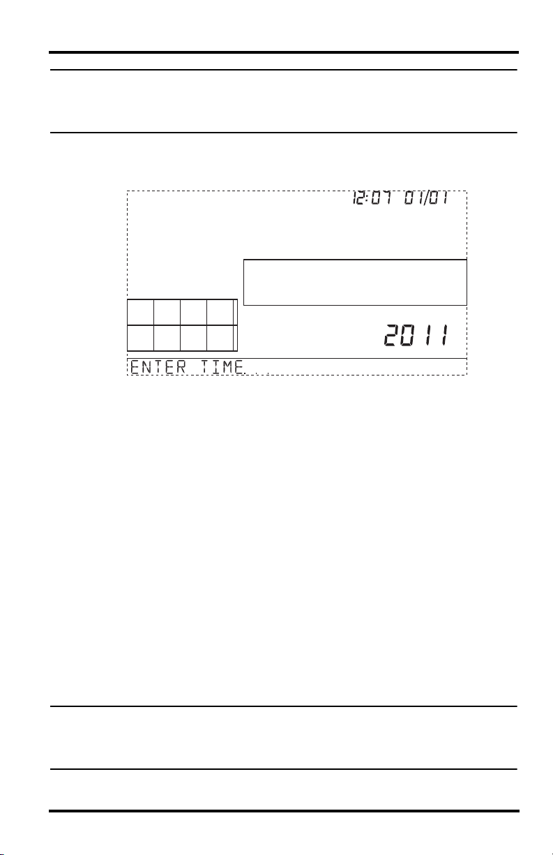
Screen 4: Time & Date
The first time you power-up the console, enter the correct date and local time.
am
Screen 4: Time & Date
To change the time and date:
1. Press the < and > keys to select the hour, minute, month, day or year. The selected
time or date setting blinks on and off.
2. To change a setting, press the + and - keys to adjust the value up or down.
To choose a 12-hour (default in US models) or 24-hour clock (default in EU and UK
models), first select either the hour or minute setting, then press 2ND and immediately press UNITS. This toggles the clock setting between the two clock types.
To choose between a MM/DD (default in US models) or DD.MM (default in EU and
UK models) display for the date, first select either the day or month setting, then
press 2ND and immediately press UNITS. This switches the console from one date
display to the other.
3. Press DONE to move to the next screen.
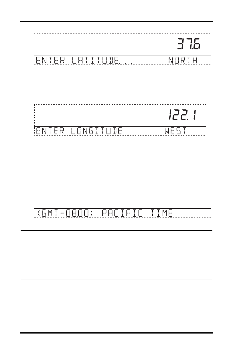
Screen 5 and Screen 6: Latitude and Longitude
The console uses latitude and longitude to determine your location, allowing it to adjust
the forecast and calculate the times for sunset and sunrise.
• Latitude measures distance north or south of the equator.
• Longitude measures distance east or west of the Prime Meridian, an imaginary line
running north and south through Greenwich, England.
Note: You can find your latitude and longitude by searching the internet (for example:
googlemaps.com, earth.google.com or earthtools.org). Many atlases and maps
include latitude and longitude lines. You can also talk to the reference department of
your local library, call your local airport, or search on the Internet.
12
Setup Mode
The more accurate you are, the better; however, a reasonable estimate will work, too.
Screen 5: Latitude
1. Press the < and > keys to move between fields.
2. Press the + and - keys to change the settings up or down.
3. To select between SOUTH or NORTH, press 2ND and then UNITS.
4. Press DONE to move to the Longitude screen.
Screen 6: Longitude
1. Press the < and > keys to move between fields.
2. Press the + and - keys to change the settings up or down.
3. To select the East or West Hemisphere, press 2ND, then UNITS.
4. Press DONE to move to the next screen.
Screen 7: Time Zone
The console is pre-programmed with a combination of US time zones and the names of
major cities representing time zones around the world. You can also configure your
time zone using the Universal Time Coordinate (UTC) offset.
Screen 7: Time Zone
Note: UTC offset measures the difference between the time in any time zone and a stan-
dard time, set by convention as the time at the Royal Observatory in Greenwich,
England. Hayward, California, the home of Davis Instruments, observes Pacific Standard Time. The UTC offset for Pacific Standard Time is -8:00, or eight hours behind
Universal Time (UTC). When it’s 7:00 pm (1900 hours) UTC, it’s 19 - 8 = 1100 hours,
or 11:00 am in Hayward in winter. When daylight saving time is observed, an hour is
added to the offset time automatically. Use this function in correlation with Screen 8,
Daylight Saving Settings.
1. Press the + and - keys to cycle through time zones.
2. If your time zone is not shown, press 2ND then press the + and - keys to set your
UTC offset.
3. Press DONE to select the time zone or UTC offset shown on the screen and move to
the next screen.
13
Setup Mode
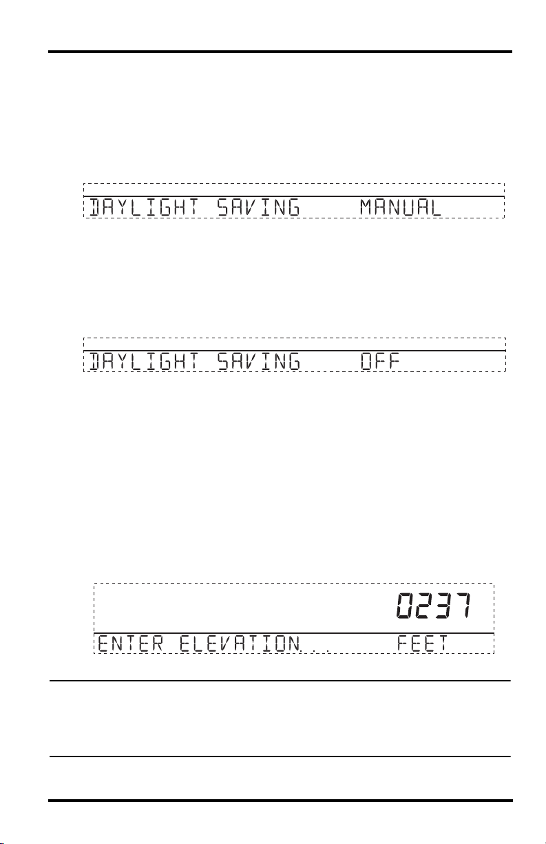
Screen 8: Daylight Saving Settings
In most of North America (except Saskatchewan, Arizona, Hawaii, and the Mexican
State of Sonora); and Europe use the AUTO daylight saving setting. The console is preprogrammed to use the correct starting and stopping dates for daylight saving time in
these areas, based on the time zone setting in screen 7.
Stations located outside North America and Europe, or in areas that do not observe daylight saving time should use the MANUAL setting.
Screen 8: Daylight Saving Settings
1. Press the + and - keys to choose Auto or Manual.
2. Press DONE to move to the next screen.
Screen 9: Daylight Saving Status
Use this screen to either verify the correct automatic daylight saving status or to set
daylight saving manually.
Screen 9: Daylight Saving Status
1. If Daylight Saving setting is MANUAL, you will have to set the time correctly when
it changes. However, to maintain accurate calculations, you also need to use the +
and - keys to turn daylight saving time on or off on the appropriate days of the year.
If you have an AUTO daylight saving setting, the console displays the appropriate
setting based on the current time and date.
2. Press DONE to move to the next screen.
Screen 10: Elevation
Meteorologists standardize barometric pressure data to sea level so that surface readings are comparable, whether they’re taken on a mountainside or by the ocean. To
make this same standardization and ensure consistent readings, enter your elevation in
this screen.
Screen 10: Elevation
Note: If you do not know your elevation, there are several ways to find out. Many atlases
and almanacs include elevation for cities and towns. You can also check with the reference department of your local library, or refer to internet resources. (See “Screen 5
and Screen 6: Latitude and Longitude” for a list of web sites.) The more accurate you
are, the better; but a reasonable estimate works too.
14
Loading...