

Page 1
LEADTEK GPS MODULE
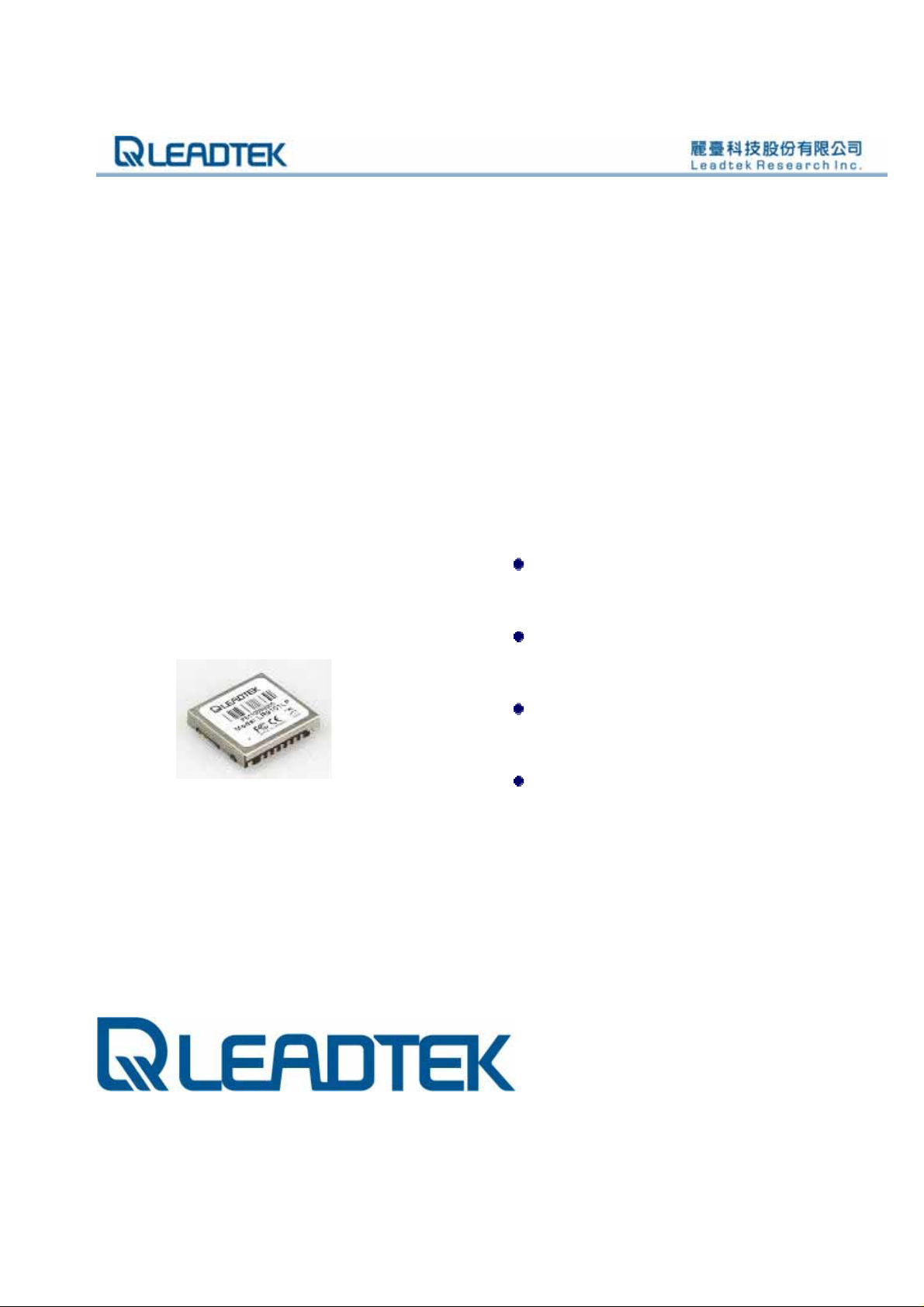
GPS LR9101LP
Specifications Sheet
Features:
SiRF StarIII low power single
chipset
Compact module size for easy
integration : 15 x 14 x 2.8 mm
Built-in high gain amplifier and
bandpass filter
RoHS compliance
ALL INFORMATION CONTAINED HEREIN IS THE SOLE PROPERTY OF LEADTEK RESEARCH AND CANNOT BE
DISSEMINATED WITHOUT THE EXPRESS WRITTEN CONSENT OF LEADTEK RESEARCH.
i
Page 2

LR9101LP Specifications Sheet Rev. 0.1
1. Introduction
The Leadtek GPS 9101LP module (LR9101) is a high sensitivity, high gain, low power and very
compact Surface Mount Device (SMD). This 20-channel global positioning system (GPS)
receiver is designed for a broad spectrum of OEM applications and is based on the fast and deep
GPS signal search capabilities of SiRFStarIII™ low power single chipset architecture. Leadtek
GPS 9101LP is designed to allow quick and easy integration into GPS-related applications,
especially for compact size devices, such as:
PDA, Pocket PC and other computing devices
e
Fleet Management / Asset Tracking
AVL and Location-Based Services
Hand-held Device for Personal Positioning and Navigation
1.1. Features
L
Hardware and Software
Based on the high performance features of the SiRF Star III low power single chipset.
Built-in high gain amplifier and bandpass filter
RoHS compliant (lead-free)
Compact module size for easy integration: 15x14x2.8 mm (590.6x551.2x110.2 mil).
P
SMT pads allow for fully automatic assembly processes equipment and reflow soldering
SiRFLocTM Client AGPS support
P
e
L
r
a
e
e
e
r
a
d
d
l
l
t
t
m
m
i
i
k
e
i
i
k
n
n
a
a
r
r
y
y
Performance
Cold/Warm/Hot Sta r t Time: 42 / 38 / 1 sec.
Reacquisition Time: 0.1 second
RF Metal Shield for best performance in noisy environments
Multi-path Mitigation Hardware
© 2006 Leadtek Research Inc. All rights reserved. Page 1/12
Preliminary Confidential - Information is subject to change without prior notice.
Page 3
LR9101LP Specifications Sheet Rev. 0.1
Interface
TTL level serial port for GPS communications interface
Protocol: NMEA-0183/SiRF Binary (default NMEA)
Baud Rate: 9600, 19200 bps (default 9600)
1.2. Advantages
Ideal for compact size devices
Data / Power / RF through surface mount pads
Cost saving through elimination of RF and board to board digital connectors
Flexible and cost effective hardware design for different application requirements
e
Secure SMD PCB mounting method
d
d
2. Technical specifications
a
a
e
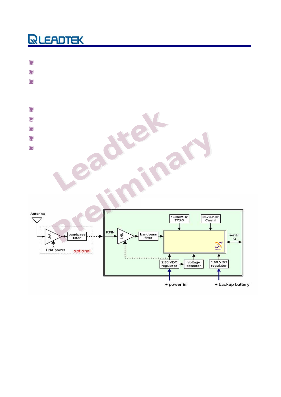
2.1. Module architecture
L
L
P
P
e
e
e
r
r
l
l
t
t
m
m
i
i
k
k
e
i
i
9101LP Block Diagram
n
n
y
y
r
r
a
a
SiRF GSC3f/LP
© 2006 Leadtek Research Inc. All rights reserved. Page 2/12
Preliminary Confidential - Information is subject to change without prior notice.
Page 4
LR9101LP Specifications Sheet Rev. 0.1
Hardware Features
Based on the high performance features of the SiRF Star III low power single chipset
Built-in high gain amplifier and bandpass filter
Compact module size for easy integration: 15x14x2.8 mm (590.6x551.2x110.2 mil)
SMT pads allow for fully automatic assembly processes equipment and reflow soldering
RoHS compliant (lead-free)
2.2. Software Features
The firmware used on Leadtek 9101LP module is GSW3.2.2, the software for SiRF StarIII low
power single chipset receivers, and the default configuration is as following description:
d
Item Description
a
Core of firmware SiRF GSW3.2.2
Baud rate 9600, 19200 bps (default 9600)
Code type NMEA-0183 ASCII
Datum WGS-84
Protocol message GGA, GSA, GSV, RMC,VTG
Output frequency 1 Hz
2.3. Mechanical specification
The Physical dimensions of the Leadtek 9101LP GPS Module are as follow:
L
P
P
e
L
e
r
r
a
e
e
d
i
i
l
l
e
t
t
m
m
k
e
i
i
k
n
n
a
a
r
r
y
y
Items Description
Length 15.0 ± 0.1 mm (590.6 ± 4 mil)
Width 14.0 ± 0.1 mm (551.2 ± 4 mil)
Height 2.80 ± 0.3 mm (110.2 ± 12 mil)
Weight 1g
© 2006 Leadtek Research Inc. All rights reserved. Page 3/12
Preliminary Confidential - Information is subject to change without prior notice.
Page 5

LR9101LP Specifications Sheet Rev. 0.1
2.4. Recommended GPS Antenna Specification
This GPS 9101LP receiver is designed for use with passive antenna.
Parameter Specification
Antenna Type Right-hand circular polarized passive antenna
Frequency Range 1575.42 ± 1.023 MHz
2.5. Environmental Specification
Item Description
Operating temperature rang -40 deg. C to +85 deg. C
Storage temperature range -55 deg. C to +100 deg. C
e
Humidity up to 95% non-condensing or a wet
L
bulb temperature of +35 deg. C
Altitude 18,000 meters (60,000 feet) max.
L
a
e
a
d
d
i
l
Velocity
e
e
Jerk 20 meters/second3, max.
Acceleration 4g, max.
P
P
r
r
l
k
k
e
e
t
t
a
a
n
n
i
i
m
m
i
515 meters/second (1000 knots)
max.
r
r
y
y
© 2006 Leadtek Research Inc. All rights reserved. Page 4/12
Preliminary Confidential - Information is subject to change without prior notice.
Page 6

LR9101LP Specifications Sheet Rev. 0.1
2.6. Reference design
k
k
e
e
t
t
d
d
a
a
a
e
L
All ground pads attach directly to gro und plane b y way of via.
All components are reference only
L
e
l
l
m
m
i
i
n
i
i
n
a
r
r
y
y
e
e
r
r
P
P
© 2006 Leadtek Research Inc. All rights reserved. Page 5/12
Preliminary Confidential - Information is subject to change without prior notice.
Page 7

LR9101LP Specifications Sheet Rev. 0.1
3. Performance Characteristics
3.1. Position and velocity accuracy
10 meters, 2D RMS
Position
Accuracy
Velocity 0.1 meters/second
Time 1 microsecond synchronized to GPS time
3.2. Dynamic constrains
Altitude 18,000 meters (60,000 feet) max.
a
Dynamic
Conditions
L
L
3.3. Acquisition time 1
P
P
(valid almanac, position, time & ephemeris)
Velocity 515 meters/second (1000 knots) max.
e
e
Acceleration 4g, max.
r
r
a
Jerk 20 meters/second
e
e
Mode
TTFF Hot
5 meters 2D RMS, WAAS corrected
<5meters(50%)
k
k
e
e
t
t
d
d
a
a
n
n
i
i
3
, max.
m
m
i
i
l
l
Leadtek 9101LP
GPS Module
r
r
1 s
y
y
TTFF Warm
(valid almanac, position, & time)
TTFF Cold
(valid almanac)
re-acquisition
(<10 s obstruction with valid almanac, position,
time & ephemeris)
Note 1: Open Sky and Stationary Environments.
© 2006 Leadtek Research Inc. All rights reserved. Page 6/12
Preliminary Confidential - Information is subject to change without prior notice.
38 s
42 s
100 ms
Page 8

LR9101LP Specifications Sheet Rev. 0.1
3.4. Timing 1PPS output
The 1PPS pulse width is 1 µs, this 1PPS is NOT suited to steer various oscillators (timing
receivers, telecommunications system, etc).
3.5. Sensitivity
Parameter Description
Tracking Sensitivity -159 dBm
k
Acquisition Sensitivity -155 dBm
3.6. Battery backup (SRAM/RTC backup)
d
d
During ‘Powered down’ condition, the SRAM and RTC (Real Time Clock may be kept
operation by supplying power from VBATT. The Leadtek 9101LP GPS module can accept slow
e
VBATT supply rise time (unlike many other SiRFstarII based receivers) due to an on-board
voltage detector.
3.7. Differential aiding
L
L
a
e
a
l
l
i
i
e
e
t
t
m
m
k
i
i
n
n
a
a
r
r
y
y
e
e
3.7.1. Differential GPS (DGPS) Option
DGPS specification improves the Leadtek 9101LP GPS Module horizontal position accuracy to
<4M 2dRMS.
3.7.2. Satellite Based augmentation System (WASS/EGONS) Option
The Leadtek 9101LP GPS Module is capable of receive SBAS(WASS and EGONS) differential
corrections. SBAS improves horizontal position accuracy by correcting GPS signal errors caused
by ionospheric Disturbances, timing and satellite orbit errors.
Both SBAS and DGPS should improve position accuracy. However, other factors can affect
accuracy, such as GDOP, multipath, distance from DGPS reference station and latency of
corrections.
© 2006 Leadtek Research Inc. All rights reserved. Page 7/12
Preliminary Confidential - Information is subject to change without prior notice.
P
P
r
r
Page 9

LR9101LP Specifications Sheet Rev. 0.1
4. Hardware InterfacePower supply
Parameter Leadtek 9101LP GPS Module
Input voltage
Current (typ) at full power (3.3V) 49mA
Battery backup voltage 1.65~5.0 VDC
4.1. sp ecifica tions
4.1.1. Pin Positions
e
L
L
e
e
e
r
r
a
a
l
l
d
d
m
m
i
i
t
t
3.2~ 5.0 VDC
k
k
e
e
a
a
n
n
i
i
r
r
y
y
P
P
© 2006 Leadtek Research Inc. All rights reserved. Page 8/12
Preliminary Confidential - Information is subject to change without prior notice.
Page 10

LR9101LP Specifications Sheet Rev. 0.1
4.1.2. Pin Assignment
PIN Name Type Description
1 RF_Gnd RF RF Ground
2 RF_IN RF RF input
3 VSS PWR Ground
4 RESETN I System reset (active low); In normal operation this pad should
be left floating. Active pull-up is not recommended
5 VCC_IN PWR 3.2 ~ 5.0 VDC input
6 VSTBY PWR 1.65 ~ 5.0 VDC RTC backup battery supply
7 RXB I TTL level asynchronous input for UART B
8 TXB O TTL level asynchronous output for UART B
9 GND 2 Ground
d
10 TXA O TTL level asynchronous output for UART A
11 RXA I TTL level asynchronous input for UART A
12 GPIO1 I Reserved, general purpose IO
13 GPIO14 I Reserved, general purpose IO
L
14 TIMEMARK O 1 PPS time mark output
15 GPIO13 I Reserved, general purpose IO
16 GPIO15 I Reserved, general purpose IO
Note 2: There are two more shielding case ground pads, please refer the recommended
footprint.
e
L
r
a
e
e
e
r
a
d
i
i
l
l
e
t
t
m
m
k
e
i
i
k
n
n
a
a
r
r
y
y
P
P
© 2006 Leadtek Research Inc. All rights reserved. Page 9/12
Preliminary Confidential - Information is subject to change without prior notice.
Page 11

LR9101LP Specifications Sheet Rev. 0.1
5. Software interface
The host serial I/O port of the module’s serial data interface supports full duplex communication
between the module and the user. The default serials are shown in Table 5-1.
Port Protocol Description
Port A NMEA 0183, 9600 bps GGA, GSA, GSV, RMC, VTG
Port B
5.1. NMEA output messages
The output NMEA (0183 v3.0) messages for the receiver are listed in Table 5-2. A complete
description of each message is contained in the SiRF NMEA reference manual.
5.2. SiRF binary
N/A N/A
k
Table 5-1 Leadtek 9101LP GPS module default baud rates
e
e
t
t
d
d
a
a
e
e
L
L
k
i
i
n
n
a
a
r
r
y
y
A complete description of each binary message is contained in the Leadtek SiRF Binary Protocol
reference manual.
P
P
r
r
e
l
e
l
m
m
i
i
© 2006 Leadtek Research Inc. All rights reserved. Page 10/12
Preliminary Confidential - Information is subject to change without prior notice.
Page 12

LR9101LP Specifications Sheet Rev. 0.1
6. Mechanical drawing
and footprint
6.1. Outline Drawing
e
e
L
L
a
a
l
l
Items Description
Length 15.0 ± 0.1 mm (590.6 ± 4 mil)
Width 14.0 ± 0.1 mm (551.2 ± 4 mil)
Height 2.80 ± 0.3 mm (110.2 ± 12 mil)
k
k
e
e
t
d
d
m
m
i
i
t
n
i
i
a
n
a
r
r
y
y
e
e
r
r
P
P
© 2006 Leadtek Research Inc. All rights reserved. Page 11/12
Preliminary Confidential - Information is subject to change without prior notice.
Page 13

LR9101LP Specifications Sheet Rev. 0.1
k
k
L
L
e
e
a
a
d
d
t
t
e
e
i
i
n
n
a
a
r
r
y
y
m
m
i
i
l
l
e
e
r
r
P
P
6.2. Recommended footprint ( Bottom view )
© 2006 Leadtek Research Inc. All rights reserved. Page 12/12
Preliminary Confidential - Information is subject to change without prior notice.
Page 14

LR9101LP Specifications Sheet Rev. 0.1
k
k
L
L
e
e
a
a
d
d
t
t
e
e
i
i
n
n
a
a
r
r
y
y
m
m
i
i
l
l
e
e
r
r
P
P
Note 3: These two shielding case ground pads should attach directly to a ground plane.
© 2006 Leadtek Research Inc. All rights reserved. Page 13/12
Preliminary Confidential - Information is subject to change without prior notice.
 Loading...