

Page 1

Installation Guide
AME (-H) 610, 613, 633
ENGLISH
DEUTSCH
FRANCAIS
MAG YAR
POLSKI
中文
VFG 2
VFG 21
VFG 25
Electrical Actuator AME (-H) 610, 613, 633 www.danfoss.com Page 7
Elektrischer Stellantrieb AME (-H) 610, 613, 633 www.danfoss.de Seite 9
Servo-moteurAME (-H) 610, 613, 633 www.danfoss.fr Page 12
Elektromos szelepmozgató AME (-H) 610, 613, 633 www.danfoss.hu Oldal 15
Siłownik elektryczny AME (-H) 610, 613, 633 www.danfoss.pl Strona 18
电动调节阀驱动器 AME(-H) 610,613,633 www.danfoss.com 第 21 页
VFU 2 VFGS 2 AFQM
Danfoss Heating VI.AA.X3.6U DH-SMT/SI
1
Page 2

2
L
B
L
B
1
Installation Guide AME (-H) 610, 613, 633
DH-SMT/SI VI.AA.X3.6U Danfoss Heating
❶
B
VFG, VFGS DN 15-125 VFG DN 150-250
VFG, VFGS DN 150-250
with body extension
Valves DN 15 20 25 32 40 50 65 80 10 0 125 150 200 250
L mm 130 250 260 280 200 230 290 310 350 400 480 600 730
VFG(S)
VFG(S)
T
300
max
VFU 2
B mm 212 212 238 238 240 240 275 275 380 380 326 354 404
Weight kg 7 9 10 13 17 22 33 41 60 79 85 145 228
B1 mm - - - - - - - - - - 630 855 1205
Weight kg - - - - - - - - - - 140 210 300
B mm 95 95 106 106 123 123 13 5 135 165 165 - - -
C mm 3 11 3 11 337 337 339 339 374 374 47 9 479 - - -
Weight kg 7 9 10 13 17 22 33 41 60 79 - - -
A
C
L
VFU DN 15-125
DN 65 80 100 125
L
A 600 610 - B 425 425 530 530
B
AFQM + AMV(E) 6xx
290 310 350 400
(mm)
Page 3

Installation Guide AME (-H) 610, 613, 633
❷
Valve type
DN 15- 125 150-250 15- 125 15- 125 150-250 65 -125
PN 16, 25, 40 25
Medium Hot water Steam Hot water
T
max Medium
VFG 2
VFG 21
VFG 25
VFG 2: 200
VFG 21: 150
VFG 25: 200
VFG 2
VFG 21
140 200
VFU 2 VFGS 2 AFQM
❸
① ① ①
AFQM
AFQM
②
②
VFU 2
VFU 2
300 (PN 16)
350 (PN 25, 40)
300 150
VFG 2 (21, 25)
VFG 2 (21, 25)
②
③
VFGS 2
Danfoss Heating VI.AA.X3.6U DH-SMT/SI
33
Page 4

4
PE
L
N
0(4) - 20 mA
0(2) - 10 V
GND
0(4) - 20 mA
0(2) - 10 V
Valve Open
End switches
Valve Close
Power supply
Output stroke
Input controller
①
①
20
19
18
17
16
15
14
13
12
11
10
9
8
7
6
5
4
3
2
1
Installation Guide AME (-H) 610, 613, 633
DH-SMT/SI VI.AA.X3.6U Danfoss Heating
❹
❻
①
②
❺
❼
OPEN
STOP
AUTO
STOP
CLOSE
③
①
②
④
DN 150-250
②
②
①
❽ ❾
①
②
③
Page 5

Installation Guide AME (-H) 610, 613, 633
❿
①
⓫
VFG.., AFQ
①
②
S1
S2
S2
②
CLOSE
OPEN
STOP
AUTO
STOP
③
21
21
0/2-10 V
0/4-20 mA
0-20 mA
4
S2
3
3
0-20 mA
0-10 V
4-20 mA
2-10 V
0.74 mA
0.72 V
VFG..
AFQ
VFU
0-10 V
20 mA
10 V
4
4-20 mA
2-10 V
④
⑥
1
⑤
⑧
OPEN
STOP
AUTO
STOP
CLOSE
S2
⑨
1
VFG.., AFQ
⑩
⑪
S2
CLOSE
OPEN
STOP
AUTO
STOP
③
1
⑦
⑮
⑬
S2
1
⑯
⑫
OPEN
STOP
AUTO
STOP
CLOSE
⑭
OPEN
STOP
AUTO
STOP
CLOSE
⑰
Danfoss Heating VI.AA.X3.6U DH-SMT/SI
55
Page 6

Installation Guide AME (-H) 610, 613, 633
⓬
VFU
⑩
①
S2
⑪
②
OPEN
STOP
AUTO
STOP
CLOSE
S2
1
⑥
⑧
④
OPEN
⑤
STOP
AUTO
STOP
CLOSE
③
1
⑭
⑦
⑬
⑯
S2
⑨
⑰
1
S2
1
⓭
VFU
OPEN
STOP
AUTO
STOP
CLOSE
OPEN
STOP
AUTO
STOP
CLOSE
①
③
OPEN
STOP
AUTO
STOP
CLOSE
VFG.., AFQ
②
④
⑫
VFU
VFUVFG.., AFQ
OPEN
STOP
AUTO
STOP
CLOSE
⓮
OPEN
STOP
AUTO
STOP
CLOSE
⑤
③
⑮
OPEN
STOP
AUTO
STOP
CLOSE
⑱
②
①
④
VFUVFG.., AFQ
OPEN
STOP
AUTO
STOP
CLOSE
⑦
⑤
6
DH-SMT/SI VI.AA.X3.6U Danfoss Heating
⑥
VFUVFG.., AFQ
Page 7

Installation Guide AME (-H) 610, 613, 633
ENGLISH
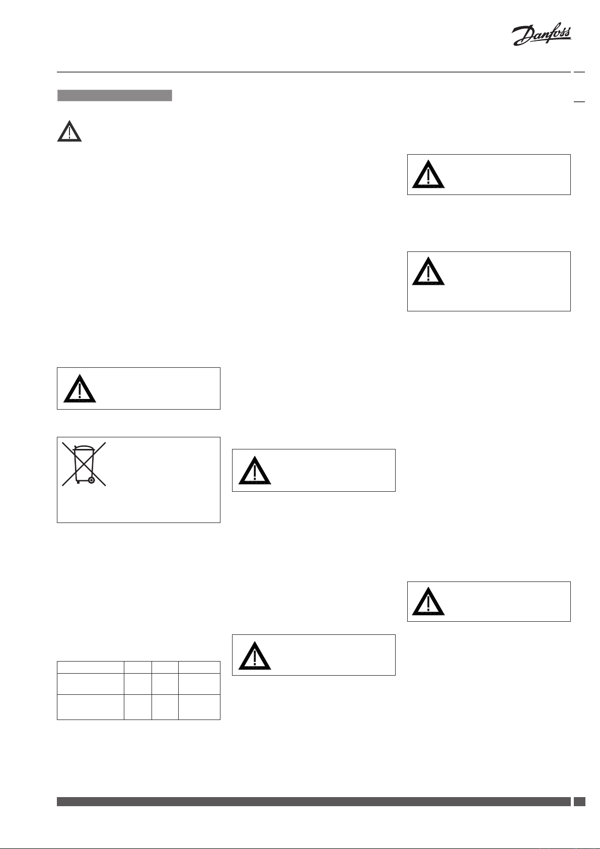
Safety Notes
Prior to assembly and commissioning
to avoid injury of persons and damages
of the devices, it is absolutely necessary
to carefully read and observe these
instructions.
Necessary assembly, start-up, and
maintenance work must be performed
only by qualified, trained and authorized
personnel.
Prior to assembly and maintenance work
on the controller, the system must be:
- depressurized,
- cooled down,
- emptied and
- cleaned.
Please comply with the instructions of the
system manufacturer or system operator.
Mounting
Permissible Installation Positions ❸
① - DN 15-50 (T
valve type AFQM -
- DN 15-80 (T
valve types VFG 2, VFG 21, VFG 25,
VFU 2
② - DN 15-250 (T
all allowed valve types
- DN 65-125 (T
valve type AFQM -
- DN 100-250 (T
valve types VFG 2, VFG 21, VFU 2
③ DN 15-250:
valve type VFGS 2 (steam).
Valve Installation ❹
1. Install strainer in front of valve.
2. Rinse system before installing valve.
3. Observe flow direction ① on the valve
body
< 120oC):
max
< 120oC):
max
> 120 oC)
max
< 120oC):
max
< 120oC):
max
Disassembly of Valve,
Actuator ❼
Danger
Danger of injury by steam or hot water! ①
Valve without actuator is open ①,
sealing ② is in the actuator.
It is absolutely necessary to depressurize
system prior to any work.
Carry out disassembly in reverse order as
assembly.
Electrical Connection
HIGH VOLTAGE !
Danger of injury and life in case of
improper handling!
Do not remove the cover before the power
supply is fully switched off.
Disposal instruction
This product should be
dismantled and its
components sorted, if
possible, in various groups
before recycling or disposal.
Always follow the local disposal regulations.
Definition of Application
The electrical actuator is used in
connection with the following valves:
VFG 2(21), VFG 25, VFU 2, VFGS 2, AFQM.
Fields of application are the temperature
control of water, water-glycol mixtures
and steam for heating, district heating and
cooling systems.
Flanges ② in the pipeline system
must be in parallel direction, the
sealing surfaces must be clean and
undamaged.
4. Install valve.
5. Tighten screws crosswise in 3 steps up
to the maximum torque.
Actuator and Valve Installation ❺
Before mounting:
1. Carry out the electrical connection
procedure acc. to the next paragraph
2. turn the rotary switch to the postion
“OPEN” ① to run the actuator stem ②
completely back
Valves DN 150-250
For valves DN 150 - 250 the stem of the
actuator must be screwed into the valve
stem.
Switch off power supply prior to
connecting lines.
The electrical connection must only be
performed by an expert electrician.
To access electrical panel remove the cover
first.
Removing the cover ❽
1. Loosen slotted screw at the rotary
switch ①, remove rotary switch.
2. Unscrew screw ② and remove cover ③.
Connections
When cover is removed connect lines in
accordance with connection diagram, see ❾:
① Connection for:
STB - Safety Temperature Limiter
STW - Safety Temperature Monitor
SDB - Safety Pressure Limiter
Prior to remounting the cover, carry out
settings at the actuator, see next section.
Overview Actuators AME 6..
610/3 0 613/3 3 (-H )613/33
Safety
function
Mechanical
adjustment
- + +
- - +
Dimensions, Weights ❶
Flanges: Connection dimensions acc. to
EN 1092-2
Observe the Installation Instructions ③
attached to valves DN 150-250.
Valves DN 15-125
1. Place actuator on the valve and align.
2. Tighten union nut ④ torque 100 Nm
Insulation ❻
Prior to connection it is absolutely
necessry to remove the jumper ① -
only types AME (-H) 613, 633 with safety
return function.
Actuator Settings ❿
Prior to carrying out any settings,
dismount cover like described in previous
section.
Valve Types for AME(-H) 6..
The electical actuator AME(-H) 6.. can be
mounted on the following valves, see ❷.
Danfoss Heating VI.AA.X3.6U DH-SMT/SI
77
Page 8

8
Installation Guide AME (-H) 610, 613, 633
DH-SMT/SI VI.AA.X3.6U Danfoss Heating
Switch designations ❿ ①
Output Signal Settings ❿ ②
Input settings ❿ ③
The selection of voltage or current input
is carried out via the connection on the
terminal strip, terminal 15 or 16, see
“Electrical diagram” ❾.
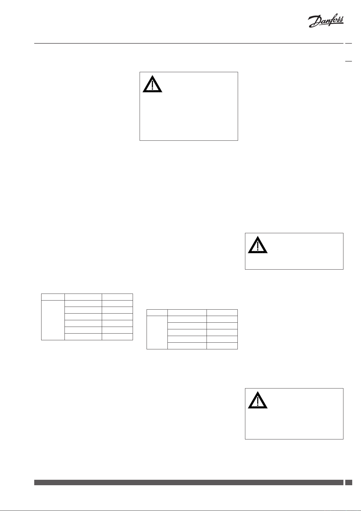
Final Position Settings
After having mounted the valves and the
actuator, the final positions “Valve OPEN”
and “Valve CLOSED” must be set.
Pre-conditions for the settings:
• theactuatorismountedonthevalve
•
the electrical connection is completed.
Valves VFG .., AFQM ⓫
Setting the final position
“Valve CLOSED” ①
Procedure:
1. Set switch S2 ②
2. Set rotary switch to position “CLOSE” ③.
3. The stroke indicator ④ must move in
the direction of the arrow up to its stop.
Valve is completely closed.
4. Align stroke indicator:
• Loosenscrews⑤.
• Aligndisplayto0⑥.
• Tightenscrews.
5. Turn rotary switch by one position to
STOP ⑦
6. Press key S4 once ⑧
7. Set switch S2 ⑨
The final position “Valve CLOSED” is set.
Setting the final position
“Valve OPEN” ⑩
Procedure:
1. Find the stroke in the table below:
Typ e
VFG 2
VFG 21
VFG 25
AFGM
2. Set switch S2 ⑪
3. Set rotary to position “OPEN” ⑫
Valve opens
Example:
DN 100, Stroke 20 mm
As soon as the stroke ⑬ has been
reached , set rotary switch to position
“STOP” ⑭
4. Press key S4 once ⑮
DN
15, 20, 25
32, 40
50, 65
80
100, 125
150, 200, 250
Valve stroke
6 mm
8 mm
12 mm
18 mm
20 mm
24 mm
5. Set switch S2 ⑯
The final position “Valve OPEN” is set.
After you completed setting final position
re-mount the cover and rotary switch and
turn rotary switch to position "AUTO" ⑰.
If you would like to reset the final
positions repeat the procedure ⓫ again.
Valves VFU 2 ⓬
Remarks to VFU 2:
In contrary to the valves VFG .., AFQM ,
the valve VFU 2 has a reversed closing
direction.
The valve VFU 2 is opened by the safety
return function.
Setting the final position
“Valve OPEN” ①
Procedure:
1. Set switch S2 ②
2. Set rotary switch to position “CLOSE” ③.
3. The stroke indicator ④ must move in
the direction of the arrow up to its stop.
Valve is completely open ①
4. Align stroke indicator:
• Loosenscrews⑤.
• Aligndisplayto0⑥.
• Tightenscrews.
5. Turn rotary switch by one position to
“STOP” ⑦
6. Press key S4 once ⑧
7. Set switch S2 ⑨
The final position “Valve OPEN” is set.
Setting the final position
“Valve CLOSED” ⑩
Procedure:
1. Take stroke from the following table:
Typ e
VFU
2. Set switch S2 ⑪
3. Set rotary switch to position “OPEN” ⑫
Valve closes, as soon as the stroke ⑬
has ben reached, set rotary switch to
position “STOP” .
4. Stroke indicator moves up to its stop,
the valve is shown on the scale ⑭
Example:
DN 100, stroke 20 mm
5. Turn rotary switch by one position to
“STOP” ⑮
DN
15, 20, 25
32, 40
50, 65
80
100, 125
Valve stroke
6 mm
8 mm
12 mm
18 mm
20 mm
6. Pres key S4 once ⑯
7. Set switch S2 ⑰
The final position “Valve CLOSED” is set.
After you completed setting final position
re-mount the cover and rotary switch and
turn rotary switch to position "AUTO" ⑱.
If you would like to reset the final
positions repeat the procedure ⓬ again.
Operation
Electrical Manual Adjustment ⓭
• Rotaryswitchsetto“CLOSE“①
Actuator stem is extended ②:
After repositioning, turn to “STOP”
• Rotaryswitchsetto“OPEN“③
Actuator stem is retracted ④:
After repositioning, turn to “STOP”
• Rotaryswitchsetto“STOP“
Actuator stem stays in its last position.
• Rotaryswitchsetto“AUTO“⑤
Actuator is controlled via the external
controller.
Standard setting
Strictly observe for normal operation.
Mechanical Manual Adjustments ⓮
(only for the actuators AME-H 613)
In case of a power supply failure or a
operating fault, the valve may be opened
or closed
1. Turn rotary switch to position
“CLOSE” ①.
2. Loosen security screw ②.
3. With hook wrench (accessory) retract
actuator stem ③:
VFG .., AFQM opens ④
VFU 2 closes ④
4. With hook wrench (accessory) extend
actuator stem ⑤:
VFG .., AFQM closes ⑥
VFU 2 opens ⑥
Prior to switching to automatic operation
(AUTO), it is absolutely necessary to
completely turn the adjustment nut ⑤ to
its stop.
Tighten security screw ⑦.
If this is not observed, the valve cannot be
closed. (VFU ... not be opened).
Page 9
Installation Guide AME (-H) 610, 613, 633
DEUTSCH
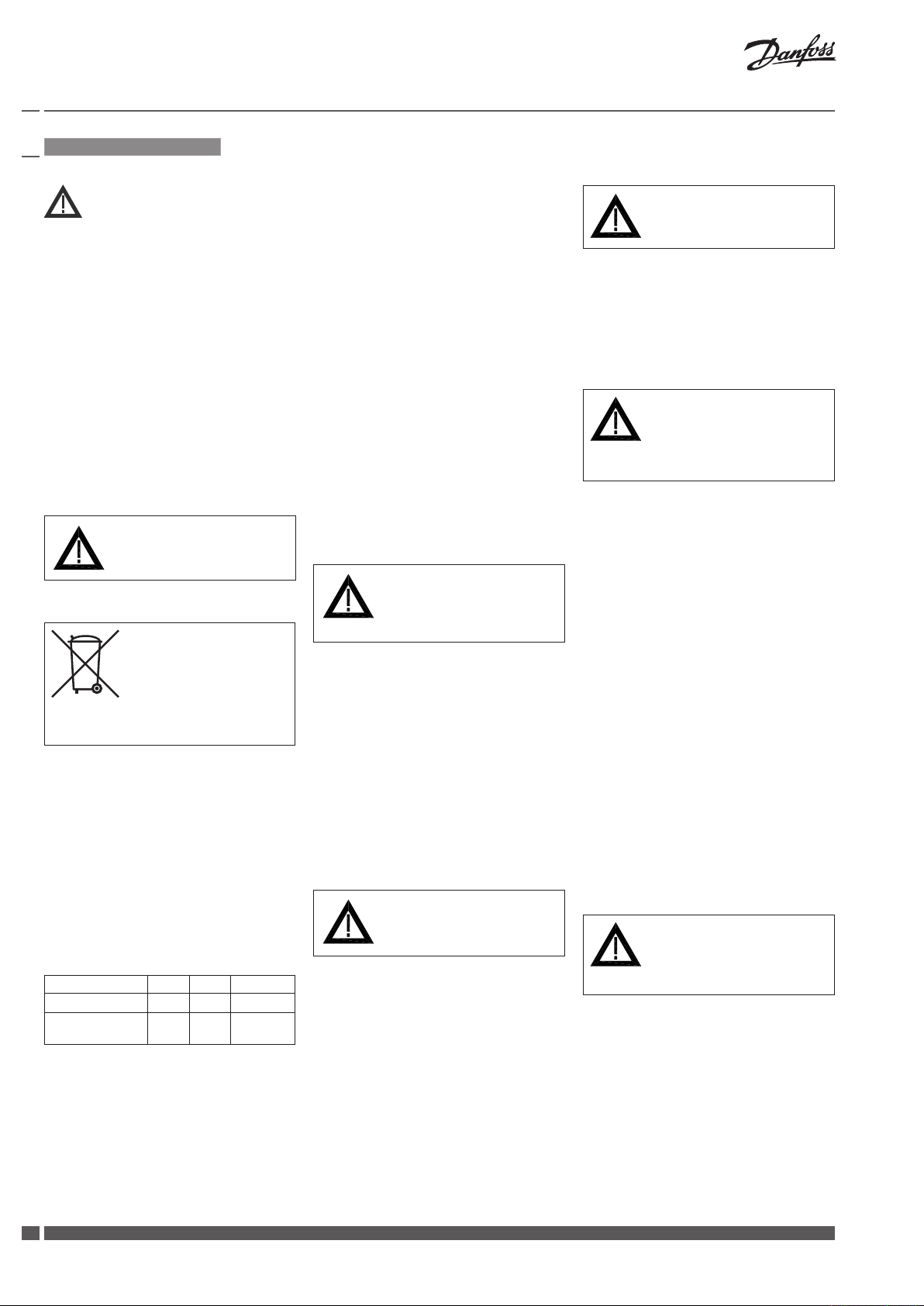
Sicherheitshinweise
Vor dem Einbau und der Inbetriebnahme
ist zur Vermeidung von Personenschäden
und Schäden an den Geräten die
vorliegende Betriebsanleitung sorgfältig
durchzulesen und unbedingt zu beachten.
Einbau-, Inbetriebnahme- und
Wartungsarbeiten dürfen nur durch
geschultes und autorisiertes Fachpersonal
durchgeführt werden.
Vor dem Einbau des Ventils und der
anschließenden Montage des Stellantriebs
und vor Wartungsarbeiten an der
Ventileinheit muss die Anlage:
- drucklos gemacht werden
- abkühlen
- entleert werden
- gereinigt werden.
Die Vorgaben des Anlagenherstellers oder
des Anlagenbetreibers sind zu beachten.
Entfernen Sie die Abdeckung
nicht, bevor die Stromversorgung
komplett ausgeschaltet ist.
Entsorgungshinweise
Vor der Entsorgung ist der
Stellantrieb zu zerlegen. Die
einzelnen Komponenten sind
dann, nach Werkstoffen
getrennt, zu entsorgen.
Entsorgungsbestimmungen sind zu
beachten.
Bestimmungsgemäße Verwendung
Der elektrische Stellantrieb wird in
Verbindung mit den folgenden Stellventilen
eingesetzt: VFG 2 (21), VFG 2, VFGS2, AFQM.
Einsatzgebiete sind die Temperaturregelung
von Wasser, Wasser-Glycolgemischen und
Dampf für Heizungs-, Fernheizungs- und
Kühlungsanlagen.
Übersicht Stellantriebe AME ...
AME 610 /30
Sicherheitsfunktion
Mechanische
Handverstellung
Abmessungen, Gewichte ❶
Flansch: Anschlussmaße EN 1092-2
613/3 3
(-H )613/33
- + +
- - +
Ventiltypen für AME(-H) 6..
Der elektrische Stellantrieb AME (-H) 6..
kann auf folgende Ventile montiert werden,
siehe ❷.
Montage
Zulässige Einbaulagen ❸
① - DN 15-50 (T
Ventiltyp AFQM -
- DN 15-80 (T
Ventiltypen VFG 2, VFG 21, VFG 25,
VFU 2
② - DN 15-250 (T
alle zulässigen Ventiltypen
- DN 65-125 (T
Ventiltyp AFQM -
- DN 100-250 (T
Ventiltypen VFG 2, VFG 21, VFU 2
③ DN 15-250:
Ventiltyp VFGS 2 (Dampf)
Einbau Ventil ❹
1. Schmutzfänger vor dem Ventil einbauen.
2. Anlage vor dem Einbau des Ventils spülen.
3. Durchflussrichtung ① uf dem
Ventilgehäuse beachten.
4. Ventil einbauen.
5. Schrauben über Kreuz in 3 Stufen bis
zum max. Drehmoment anziehen.
Montage Stellantrieb und Ventil ❺
Vor der Montage:
1. “Elektrischen Anschluss durchführen,
siehe nächsten Abschnitt
2. Drehschalter auf Stellung “OPEN” ①
drehen, dadurch Antriebsstange ②
ganz einfahren
Ventile DN 150 - 250
Bei den Ventilen DN 150 - 250 muss die
Antriebstange in die Ventilstange
eingeschraubt werden.
Ventile DN 15 - 125
1. Stellantrieb am Ventil ansetzen und
ausrichten
2. Überwurfmutter ④ anziehen
Anzugsmoment 100 Nm
Isolierung ❻
< 120oC):
max
< 120oC):
max
> 120 oC)
max
< 120oC):
max
< 120oC):
max
Flansche ② in der Rohr-leitung
müssen parallel, Dichtflächen sauber
und ohne Beschädigung sein.
Den Ventilen DN 150 - 250
beigefügte Montageanlei-tung
beachten.
Demontage von Stellventil und
Stellantrieb ❼
Ventil ist ohne Antrieb offen ①,
Gefahr
Verletzungsgefahr durch
Heißwasser ①
Abdichtung ② befindet sich im Antrieb.
Vor Demontage Anlage unbedingt
drucklos machen.
Demontage in umgekehr-ter Reihenfolge
wie die Montage durchführen.
Gefahr durch
Stromschlag!
Bei unsachgemäßer Handhabing besteht
Lebens- und Verletzungsgefahr!
Elektrischer Anschluss
Vor dem Anschluss der Leitungen unbedingt
Spannungsversorgung abschalten.
Durchführung des elektrischen Anschlusses
nur durch Elektrofachkraft.
Um den elektrischen Anschluss vornehmen zu
können, muss erst der Deckel entfernt werden.
Vorgehensweise ❽
1. Schlitzschraube am Drehschalter ①
lösen, Drehschalter abziehen
2. Schraube ② herausschrauben und
Deckel ③ abnehmen
Elektrischer Anschluss
Nach dem Entfernen des Deckels kann die
Verdrahtung gemäß Anschlussplan erfolgen ❾.
① Anschluss für:
STB -Schutz-Temperaturbegrenzer
STW -Schutz-Temperaturwächter
SDB - Sicherheitsdruckbegrenzer
Vor der Montage des Deckels alle
Einstellungen vornehmen.
Bei Anschluss unbed ingt Brücke
entfernen ① - nur Typen AME (-H)
613, 633 mit Sicherheitsfunktion.
Einstellung Stellantrieb ❿
Bevor die Einstellungen vorgenommen
werden können, Deckel wie beschrieben
entfernen ③❽.
Schalterbezeichnungen ❿ ①
Einstellung Ausgangssignal ❿ ②
Einstellung Eingangssignal ❿ ③
Auswahl Spannungs- oder Stromeingang
erfolgt über den Anschluss an der
Klemmleiste, Klemme 15 oder 16, siehe
“Elektrischer Anschlussplan” ❾
Danfoss Heating VI.AA.X3.6U DH-SMT/SI
99
Page 10

10
Installation Guide AME (-H) 610, 613, 633
DH-SMT/SI VI.AA.X3.6U Danfoss Heating
Einstellung der Endlagen
Nach der Montage Ventil und Stellantreib
müssen die Endlagen “Ventil AUF” und
“Ventil ZU” eingestellt werden.
Voraussetzung für die Einstellung:
• derStellantriebistaufdasVentil
montiert
• der elektrische Anschluss ist erfolgt
Ventile VFG .., AFQM ⓫
Endlage “Ventil ZU” ① einstellen
Vorgehensweise
1. Schalter S2 einstellen ②
2. Drehschalter auf Stellung “CLOSE” ③
stellen
3. Hubanzeige ④ muss sich in Pfeilrichtung
bis zum Anschlag bewegen
Ventil ist ganz geschlossen
4. Hubanzeige ausrichten:
• Schrauben ⑤ lösen
• Anzeige auf 0 ausrichten ⑥
• Schrauben anziehen
5. Drehschalter um eine Stellung, auf
STOP, weiterdrehen ⑦
6. Schalter S2 einstellen ⑧
7. Taste S4 einmal drücken ⑨
Endlage “Ventil ZU” ist eingestellt.
Endlage “Ventil AUF” einstellen ⑩
Vorgehensweise
1. Ventilhub aus der folgenden Tabelle
ablesen
Typ
VFG 2
VFG 21
VFG 25
AFGM
1. Schalter S2 einstellen ⑪
2. Drehschalter auf Stellung “CLOSE”
drehen ⑫
Ventil öffnet
Beispiel: DN 100, Ventilhub 20 mm
sobald der Ventilhub ⑬ erreicht
ist, Drehschalter um eine Stellung
weiterdrehen auf “STOP”⑭
3. Taste S4 einmal drücken ⑮
4. Schalter S2 ⑯ einstellen
Einstellung der Endlagen ist
abgeschlossen.
Nach Beendigung der Einstellungen,
Deckel und Drehschalter montieren und
Drehschalter auf Position "AUTO" drehen ⑰.
DN
15, 20, 25
32, 40
50, 65
80
100, 125
150, 200, 250
Ventilhub
6
8
12
18
20
24
Ventile VFU 2 ⓬
Anmerkungen zu VFU 2:
Das Ventil VFU 2 hat gegenüber den Ventilen
VFG .., AFQM eine umgekehrte Schließrichtung.
Das Ventil VFU 2 wird durch die
Sicherheits-funktion geöffnet.
Endlage “Ventil AUF” ① einstellen
Vorgehensweise
1. Schalter S2 einstellen ②
2. Drehschalter auf Stellung “CLOSE” ③
stellen.
3. die Hubanzeige ④ muss sich in
Pfeilrichtung bis zum Anschlag bewegen
Ventil ist ganz geöffnet ①
4. Hubanzeige ausrichten:
• Schrauben⑤ lösen
• Anzeigeauf0⑥ ausrichten
• Schraubenanziehen
5. Drehschalter um eine Stellung auf STOP
weiterdrehen ⑦
6. Schalter S2 einstellen ⑧
7. Taste S4 einmal drücken ⑨
Endlage “Ventil AUF” für Ventil VFU 2 ist
eingestellt.
Endlage “Ventil ZU” einstellen ⑩
Vorgehensweise
1. Ventilhub aus der folgenden Tabelle
ablesen
Typ
VFU
1. Schalter S2 einstellen ⑪
2. Drehschalter auf Stellung “CLOSE”
drehen ⑫
Ventil schließt (VFU 2), die Hubanzeige ⑬
bewegt sich in Pfeilrichtung
3. die Hubanzeige bis zum Anschlag
fahren lassen, auf der Skala ⑭ wird der
Ventilhub angezeigt
Beispiel: DN 100, Ventilhub 20 mm
4. Drehschalter um eine Stellung
weiterdrehen auf “STOP” ⑮
5. Taste S4 einmal drücken ⑯
6. Schalter S2 ⑭ einstellen ⑰
Einstellung der Endlagen ist
abgeschlossen
Nach Beendigung der Einstellungen,
Deckel und Drehschalter montieren und
Drehschalter auf Position "AUTO" drehen ⑱.
DN
15, 20, 25
32, 40
50, 65
80
100, 125
Ventilhub
6
8
12
18
20
Bedienung
Drehschalterstellungen, elektrische
Handverstellung ⓭
• Drehschalter auf “CLOSE” ①
Antriebsstange fährt aus ② nach der
Verstellung auf “STOP” drehen
• Drehschalterauf“OPEN”③
Antriebsstange fährt ein ④ nach der
Verstellung auf “STOP” drehen
• Drehschalterauf“STOP”
Antriebsstange bleibt in der letzten
Position stehen
• Drehschalterauf“AUTO”⑤
Stellantrieb wird über den externen
Regler angesteuert.
Standardeinstellung
für normalen Regelbetrieb unbedingt
einstellen
Mechanische Handverstellungen ⓮
(nur bei den Stellantrieben AMV-H 613)
Bei Ausfall der Spannungsversorgung oder
bei einer Störung kann das Ventil geöffnet
oder geschlossen werden
1. Drehschalter auf Stellung “OPEN”
drehen ①
2. Sicherungsschraube ② lösen
3. Mittels Hakenschlüssel (Zubehör)
Antriebsstange ③ einfahren
VFG .., AFQ öffnet
VFU 2 schließt
4. Mittels Hakenschlüssel Antriebsstange
ausfahren ⑤
VFG .., AFQ schließt
VFU 2 öffnet
Vor Umschaltung in den Automatikbetrieb
(AUTO) unbedingt die Einstellmutter ⑤ bis
zum Anschlag eindrehen.
Sicherungsschraube ⑦ festschrauben
Wird das nicht beachtet, dann kann
das Ventil nicht geschlossen werden
(VFU geöffnet werden).
Page 11

Installation Guide AME (-H) 610, 613, 633
Übersetzung
❶
VFG, VFGS DN 150-250
mit Gehäuseverlängerung
(
with body extension)
Ventile (Va lves)
Gewicht (Weight)
❷
Ventil Typ (Valve type)
OK (Medium)
T
(T
max OK
Heißwasser (Hot water)
Dampf (Stea m)
❺ ⓫ ⓬ ⓭ ⓮
ÖFFNEN (OPEN)
STOP (STO P)
AUTO (AUTO)
STOP (STO P)
SCHLIESSEN (CLOSE)
max medium
)
❾
Ausgang Hub (Output stroke)
Eingang Regler (Input controller)
Ventil geöffnet (Valve Open)
Endschalter (End switches)
Ventil geschlossen (Valve Close)
Spannungsver sorgung (Power supply)
Danfoss Heating VI.AA.X3.6U DH-SMT/SI
1111
Page 12
12
Installation Guide AME (-H) 610, 613, 633
DH-SMT/SI VI.AA.X3.6U Danfoss Heating
FRANCAIS
Sécurité
Montage
Dimensions, poids ❼
Pour éviter des dommages physiques et matériels, il est absolument nécessaire de lire
attentivement et de respecter ces instructions avant le montage et la mise en service.
Le travail d’assemblage, de démarrage et de
maintenance nécessaire doit être effectué
uniquement par un personnel qualifié,
formé et autorisé.
Avant le travail d'assemblage et de maintenance du contrôleur, le système doit être:
- dépressurisé
- refroidi
- vidé
- nettoyé
Suivre les instructions du fabricant du
système ou de son service.
Ne pas retirer le couvercle avant
d'avoir coupé l'alimentation.
Indications de mise au rebus
Ce produit peut être démonté
et tous ses composants classés
si possible en différentes
catégories en vue de leur
recyclage ou destruction
Dans tous les cas , suivre la législation locale
de mise au rebus.
Conditions d’utilisation
Le servomoteur électrique est utilisé en
combinaison avec les vannes suivantes
VFG 2(21), VFG 25, VFU 2, VFGS2, AFQM.
Domaines d’application : régulation de la
température de l’eau, de la température
de l’eau, de l’eau glycolée et de la vapeur
pour chauffage, chauffage urbain et
installations de réfrigération.
Vue d’ensemble moteurs AME....
AME 610 /30
Fonction de secours
Commande manuelle
Méchanique
613/3 3
(-H )613/33
- + +
- - +
Dimensions, Poids ❶
Brides : Raccordement selon EN 1092-2
Types de vannes pour AME (-H) 6..
Le moteur électrique AME (-H) 6.. peut ętre
monté sur les vannes suivantes, voir ❷.
Orientations de montage autorisées ❸
① - DN 15-50 (T
vannes AFQM -
- DN 15-80 (T
vannes VFG 2, VFG 21, VFG 25, VFU 2
② - DN 15-250 (T
tous types de vannes
- DN 65-125 (T
vannes AFQM -
- DN 100-250 (T
vannes VFG 2, VFG 21, VFU 2
③ - DN 15-250:
vannes VFGS 2 (vapeur).
< 120oC):
max
< 120oC):
max
> 120 oC)
max
< 120oC):
max
max
< 120oC):
Montage vanne ❹
1. Monter le filtre devant la vanne.
2. Rincer l’installation avant le montage
de la vanne.
3. Respecter le sens d’écoulement ①
indiqué sur le corps de la vanne.
4. Monter la vanne.
Les brides ② dans la tuyauterie
doivent être parallèles, les surfaces
d’étanchéité propres et sans
dommages.
5. Serrer les vis en 3 étapes en croix,
jusqu’au couple de rotation max.
Montage moteur et vanne ❺
Avant le montage:
1. Procéder au branchement électrique,
voir prochain paragraphe
2. Tourner le bouton rotatif sur position
“OPEN” ① , ainsi rétracter totalement la
tige du moteur ②
Vannes DN150 - 250
Pour les vannes DN150-250 la tige du moteur
doit être vissée dans la tige de la vanne.
Respecter la notice de
montage ③ jointe aux vannes
DN 150-250
Vannes DN15 - 125
1. Positionner le moteur sur la vanne et
procéder ŕ l’alignement
2. Serrer l’écrou prisonnier ④, facteur de
serrage 100 Nm
Isolation ❻
Danger
Risques de brűlures par l’eau
chaude ①
La vanne n’est pas étanche sans moteur ①,
le cône d’étanchéité ② se trouve dans
l’écrou de fixation du moteur.
Impérativement mettre l’installation hors
pression avant tout démontage.
Pour le démontage suivre la procédure de
montage dans le sens inverse.
Danger d’électrocution!
Lors d’une manipulation non
appropriée, danger de mort ou
risques de blessures.
Raccordement électrique
Avant le branchement des câbles,
impérativement couper l’alimentation.
Le branchement doit être effectué
uniquement par du personnel qualifié.
Pour accéder au bornier électrique,
retirer le couvercle.
Procédure ❽
1. Desserrer la vis au niveau du bouton
rotatif ①, retirer le bouton
2. Dévisser la vis ② et retirer le capot ③
Schéma de branchement électrique
Lorsque le couvercle est ouvert, raccorder
selon le schéma, voir ❾:
① Branchement pour :
STB – Limiteur de température de sécurité
STW – Contrôleur de température de sécurité
SDB – Limiteur de pression de sécurité
Avant de remettre le couvercle , effectuer
la configuration du moteur , voir section
suivante.
Lors du branchement,
impérativement retirer le pont ①
Uniquement types AME (-H)
613, 633 avec fonction de secours
Réglage moteur ❿
Avant les réglages, démonter le capot ③❽.
Désignation des commutateurs ❿ ①
Réglage du signal de sortie ❿ ②
Réglage du signal d’entrée ❿ ③
Le choix de l’entrée courant ou tension
se fait par le branchement sur le bornier,
borne 15 ou 16, voir «schéma de
branchement électrique» ❾.
Page 13
Installation Guide AME (-H) 610, 613, 633
Réglage des positions fins de course
Après le montage de la vanne et du moteur,
les positions fins de course «vanne ouverte»
et «vanne fermée» doivent être réglées.
Conditions pour le réglage:
• le moteur est monté sur la vanne
• le branchement électrique est effectué
Vannes VFG..., AFQM ⓫
Régler la position fin de course
«vanne fermée» ①
Procédure:
1. Régler le switch S2 ②
2. Tourner le bouton rotatif sur position
«CLOSE» ③
3. L’indication de course ④ doit se déplacer
dans le sens de la flèche jusqu’en butée
La vanne est totalement fermée
4. Aligner l’indication de course :
• Desserrer les vis ⑤
• Aligner l’affichage sur 0 ⑥
• Serrer les vis
5. Avancer le bouton rotatif d’une position
sur “STOP” ⑦
6. Régler le commutateur S2 ⑧
7. Presser 1 fois la touche S4 ⑨
La position fin de course «vanne fermée»
est réglée
Régler la position fin de course
«vanne ouverte» ⑩
1. Relever la course de la vanne dans le
tableau suivant
Typ e
VFG 2
VFG 21
VFG 25
AFGM
2. Régler le switch S2 ⑪
3. Tourner le bouton rotatif sur position
“OPEN” ⑫
La vanne ouvre
Exemple : DN100, course de la vanne
20 mm Dčs que la course de la vanne
est atteinte, avancer le bouton rotatif
d’une position sur «STOP» ⑭
4. Presser une fois la touche S4 ⑮
5. Régler le commutateur S2 ⑯
Le réglage des positions fins de course
est terminé.
Une fois le paramétrage réalisé , remonter
le couvercle et le bouton tournant en le
mettant sur "AUTO" ⑰.
Si vous souhaitez remettre à zéro le réglage
de course , répéter la procédure ⓫.
DN
15, 20, 25
32, 40
50, 65
80
100, 125
150, 200, 250
Course vanne
6
8
12
18
20
24
Vannes VFU2 ⓬
Remarques concernant VFU2 :
La vanne VFU2 a un sens de fermeture
contraire par rapport aux vannes
VFG..., AFQM
La vanne VFU2 est ouverte par la fonction
de secours.
Régler la position fin de course
«vanne ouverte» ①
Procédure:
1. Régler le switch S2 ②
2. Tourner le bouton rotatif sur position
«CLOSE» ③
3. L’indication de course ③ doit se déplacer
dans le sens de la flèche jusqu’en butée
La vanne est totalement ouverte ①
4. Aligner l’indication de course :
• Desserrerlesvis⑤
• Alignerl’achagesur0⑥
• Serrerlesvis
5. Avancer le bouton rotatif d’une position
sur “STOP” ⑦
6. Régler le commutateur S2 ⑧
7. Presser 1 fois la touche S4 ⑨
La position fin de course «vanne ouverte»
pour vanne VFU2 est réglée.
Régler la position fin de course
«vanne fermée» ⑩
1. Relever la course de la vanne dans le
tableau suivant
Typ e
VFU
2. Régler le switch S2 ⑪
3. Tourner le bouton rotatif sur position
“CLOSE” ⑫
La vanne ferme (VFU2), l’indication de
course ⑬ se déplace dans le sens de la
flèche
4. Laisser aller l’indication de course
jusqu’en butée. La course de la vanne
est indiquée sur l’échelle ⑭
Exemple : DN100, course de la vanne
20 mm
5. Avancer le bouton rotatif d’une position
sur «STOP» ⑮
6. Presser 1 fois la touche S4 ⑯
7. Régler le commutateur S2 ⑰
Le réglage des positions fins de course
est terminé
DN
15, 20, 25
32, 40
50, 65
80
100, 125
Course vanne
6
8
12
18
20
Une fois le paramétrage réalisé , remonter
le couvercle et le bouton tournant en le
mettant sur "AUTO" ⑱.
Si vous souhaitez remettre à zéro le réglage
de course , répéter la procédure ⓬.
Manipulation
Positions du bouton rotatif,
commande manuelle électrique ⓭
• Bouton rotatif sur «CLOSE» ①
La tige du moteur descend ②
Après l’ajustement, tourner sur «STOP»
• Boutonrotatifsur«OPEN»③
La tige du moteur se rétracte ④
Après l’ajustement, tourner sur «STOP»
• Boutonrotatifsur«STOP»
La tige du moteur reste dans sa dernière
position
• Boutonrotatifsur«AUTO»⑤
Le moteur est commandé par un
régulateur extérieur
Réglage standard
A régler impérativement pour une
régulation normale
Commande manuelle mécanique ⓮
(Uniquement pour moteurs AME-H 613)
Lors d’une coupure de l’alimentation ou
lors d’une perturbation, la vanne peut être
ouverte ou fermée
1. Tourner le bouton rotatif sur position
«OPEN» ①
2. Desserrer la vis de sécurité ②
3. Rétracter la tige à l’aide d’une clé à
griffes (accessoire) ③
VFG..., AFQ ouvre ④
VFU2 ferme④
4. Descendre la tige à l’aide d’une clé à
griffes (accessoire) ⑤
VFG..., AFQ ferme ⑥
VFU2 ouvre ⑥
Avant de commuter dans le mode de
fonctionnement automatique (AUTO),
impérativement serrer l’écrou de
réglage jusqu’en butée ⑤.
Serrer la vis de sécurité ⑦
En cas de non-respect, la vanne ne peut
pas être fermée (VFU ouverte).
Danfoss Heating VI.AA.X3.6U DH-SMT/SI
1313
Page 14

14
Installation Guide AME (-H) 610, 613, 633
DH-SMT/SI VI.AA.X3.6U Danfoss Heating
Translation
❶
VFG, VFGS DN 150-250
avec extension de corps
(
with body extension)
Vannes (Va lves)
Poids (Weight)
❷
Type de vanne (Valve type)
Fluide (Medium)
T
(T
maxi fluid e
Eau chaude (Hot water)
Vapeur (Steam)
❺ ⓫ ⓬ ⓭ ⓮
OUVRIR (OPEN)
STOP (STO P)
AUTO (AUTO)
STOP (STO P)
FERMER (CLOSE)
max medium
)
❾
Sortie copie signal (Output stroke)
Signal d'entrée (Input controller)
Vanne ouverte (Valve Open)
Fins de course (End switches)
Vanne fermée (Valve Close)
Alimentation (Power supply)
Page 15

Installation Guide AME (-H) 610, 613, 633
MAG YAR
Biztonsági elõírások
Szerelés
Szigetelés ❻
Az itt leirt utasítások gondos elolvasása és
betartása feltétlenül szükséges a személyi
sérülések és berendezés károsodások
elkerülésére.
A szükséges szerelési, beüzemelési
és karbantartási munkákat kizárólag
szakképzett és azzal megbízott személyzet
végezheti el.
Fel- és leszerelés elõtt helyezze a rendszert
nyomásmentes állapotba.
- nyomásmentesítve,
- lehűtve,
- leürítve és,
- megtisztítva.
A rendszer gyártó vagy rendszer
üzemeltetõ elõírásait tartsuk be.
Ne távolítsa el a fedelet a tápfeszültség
teljes lekapcsolása előtt.
Hulladékelhelyezési utasítás
A hulladékban történő
elhelyezés, vagy újrahasznosítás előtt ezt a terméket, ha
van rá mód, szét kell szerelni,
alkatrészeit szét kell válogatni
és csoportosítani.
Mindig tartsa be a helyi hulladékkezelési
szabályokat.
Alkalmazások leírása
Az elektromos szelepmozgatót a következõ
szelepekhez csatlakoztatva használjuk:
VFG 2(21), VFG 25, VFU 2, VFGS 2, AFQM.
Alkalmazási területek: Víz, víz-glikol
keverékek, és gõz hõmérséklet zabályozása
fûtõ, távfûtõ és hûtõ rendszerekben.
Áttekintés szelepmozgatók AME 6..
610/3 0 613/3 3 (-H )613/33
Biztonsági
funkció
Mechanikus
beállítás
- + +
- - +
Méretek és súlyok ❶
Peremek: csatlakozási méretek a EN 1092-2
Szeleptípusok az AME(-H) 6..
mozgatóhoz
Az AME (-H) 6.. szelepmozgató a következõ
szelepekre szerelhetõ, - lásd a ❷.
Megengedett beépítési helyzetek ❸
① - DN 15-50 (T
szeleptípus AFQM -
- DN 15-80 (T
szeleptípus VFG 2, VFG 21, VFG 25,
VFU 2
② - DN 15-250 (T
minden megengedett szeleptípus
- DN 65-125 (T
AFQM típus -
- DN 100-250 (T
VFG2, VFG21, VFU szeleptípusok
③ DN 15-250:
VFGS 2 szeleptípus (gőz).
< 120oC):
max
< 120oC):
max
> 120 oC)
max
< 120oC):
max
< 120oC):
max
Szelep beépítés ❹
1. Szerelje fel a szûrõt a szelep elé.
2. A szelep felszerelése elõtt öblítse ki a
rendszert.
3. Tartsa be a folyásirányra ① vonatkozó
kikötést (szeleptesten feltüntetve).
A csõvezeték peremeinek ②
párhuzamosnak, a tömítõ felületeknek
pedig tisztának és sértetlennek kell lenni.
4. Szerelje fel a szelepet.
5. Átlósan és három lépésben húzza meg
a csavarokat a max. nyomatékra.
Szelepmozgató felszerelése a
szelepre ❺
Felszerelés elõtt:
1. Végezze el a mozgató elektromos
bekötését a következõ bekezdés szerint.
2. Fordítsa a forgó kapcsolót “OPEN” ①
thelyzetbe, a szelepmozgató rúd ②
teljes visszahuzásához.
Szelepek DN 150 - 250
DN 150 - 250 méretû szelepeknél a
mozgató rudat a szelepszárba kell csavarni.
Tartsa be a DN 150 - 250 méretû
szelepekhez mellékelt ③ felszerelési
utasításokat.
Szelepek DN 15 - 125
1. Helyezze a szelepmozgatót a szelepre,
és központosítsa a szelephez.
2. A hollandi anyát ④ húzza meg 100 Nm
nyomatékra.
A szelep és szelepmozgató
szétszerelése ❼
Veszély
Gõz vagy forró víz okozta sérülés veszélye! ①
A mozgató nélküli szelep nyitva van ①, a
tömítés ② a szelepmozgatóban található.
Bármilyen munka elõtt feltétlenül szükség
van a rendszer nyomásmentesítésére.
A szétszerelést végezze az összerelés
fordított sorrendjében.
Elektromos csatlakozás
Veszély - Nagyfeszültség!
Nem megfelelõ kezelés esetén sérülés és
életveszélyes.
A bekötések elõtt kapcsolja le az
energiaellátást.
Az elektromos csatlakoztatást kizárólag
szakképzett villanyszerelõ végezheti el.
Az elektromos panelhez csak a fedél
eltávolítása után lehet hozzáférni.
Eljárás ❽
1. Lazítsa meg a hornyos csavart a
forgó kapcsolónál ①, és távolítsa
el a kapcsolót.
2. Csavarja ki a csavart ② és távolítsa
el a fedelet ③.
Elektromos kapcsolási rajzok
Amikor a fedelet eltávolította, csatlakoztassa
a kábeleket a ❾-es számú rajz szerint:
① Csatlakozás:
STB - Biztonsági hõmérséklet korlátozóhoz
STW - Biztonsági hõmérséklet figyelõhöz
SDB- Biztonsági nyomás korlátozóhoz
A fedél eltávolítása előtt hajtsa végre
a következő fejezetben található
beállításokat.
Csatlakozás elõtt feltétlenül távolítsa
el az áthidalót. ① Csak a AME (-H)
613, 633 típusoknál, melyek biztonság
visszatérõ funcióval vannak ellátva.
Danfoss Heating VI.AA.X3.6U DH-SMT/SI
1515
Page 16

16
Installation Guide AME (-H) 610, 613, 633
DH-SMT/SI VI.AA.X3.6U Danfoss Heating
Szelepmozgató beállításai ❿
A beállítások elvégzése elõtt szerelje le
a fedelet ① - lásd a 9. oldalt.
Kapcsolók jelölései ❿ ①
Kimeneti jel beállításai ❿ ②
Bemenet beállításai ❿ ③
A feszültség vagy áram bemenet kiválasztása
a kapocslécre való csatlakozással történik
(15 vagy 16 csatlakozó), lásd az "Elektromos
kapcsolási rajzot” ❾.
Végsõ pozíció beállítások
A szelep és a szelepmozgató felszerelése
után, a "Szelep NYITVA” és "Szelep ZÁRVA"
végpozíciókat be kell állítani.
A beállítások elõfeltételei:
• amozgatólegyenfelszerelveaszelepre
•
az elektromos csatlakoztatás legyen
elvégezve.
Szelepek .., AFQM ⓫
“Szelep ZÁRVA” ①
végpozíció beállítása
Eljárás:
1. Állítsa át az S2 kapcsolót ②.
2. Állítsa a forgó kapcsolót a “CLOSE/
ZÁRVA” ③ állásba.
3. A löketjelzõnek ④ a nyíl irányában
ütközésig el kell mozdulni.
Ekkor a szelep teljesen zárva van.
4. Állítsa be a löketjelzõt:
• Lazítsamegacsavarokat⑤.
• Mozdítsa el a skálát a 0 ⑥ állásba.
• Húzzamegacsavarokat.
5. Fordítsa el a forgó kapcsolót egy
pozícióval a STOP helyzetbe ⑦.
6. Nyomja meg az S4 gombot ⑧ egyszer.
7. Állítsa be az S2 kapcsolót ⑨.
Ezzel a “Szelep ZÁRVA” végpozíció
beállítása befejezõdött.
“Szelep NYITVA” ⑩
végpozíció beállítása
Eljárás:
1. Keresse meg a szelep löketét a lenti
táblázatban.
Típus
VFG 2
VFG 21
VFG 25
AFGM
2. Állítsa át az S2 kapcsolót ⑪.
DN
15, 20, 25
32, 40
50, 65
80
100, 125
150, 200, 250
Szelep löket
6
8
12
18
20
24
3. Állítsa a forgó kapcsolót “OPEN/NYITVA”
állásba ⑫.
Ekkor a szelep kinyit.
Példa:
DN 100, Löket 20 mm
Mihelyt a löket elmozdulás ⑬
megtörténik, állítsa a forgó kapcsolót
“STOP” állásba ⑭.
4. Nyomja meg az S4 ⑮ ongombot egyszer.
5. Állítsa be az S2 kapcsolót ⑯.
Ezzel a “Szelep NYITVA” végpozíció
beállítása befejeződött.
Miután beállította a véghelyzetet, szerelje
vissza a fedelet és a forgó kapcsolót allítsa
a forgó kapcsolót “AUTO” állásba ⑰.
Ha szeretné a véghelyzetet resetelni,
ismételje meg a ⓫-es eljárást újra.
Szelepek VFU 2 ⓬
Megjegyzések a VFU 2 szelephez:
A VFG .., AFQM szelepekkel ellentétben, a VFU
2 ellentétes zárási iránnyal rendelkezik.
A VFU 2 szelepet a biztonsági visszatérõ
funkció nyitja.
“Szelep NYITVA” ①
végpozíció beállítása
Eljárás:
1. Állítsa át az S2 kapcsolót ②.
2. Állítsa a forgó kapcsolót a “CLOSE/
ZÁRVA” ③ állásba.
3. A löketjelzõnek ④ a nyíl irányában
ütközésig el kell mozdulni.
A szelep teljesen nyitva van ①
4. Állítsa be a löketjelzõt:
• Lazítsamegacsavarokat⑤.
• Mozdítsaelaskáláta0⑥ állásba.
• Húzzamegacsavarokat.
5. Fordítsa el a forgó kapcsolót egy
pozícióval a STOP helyzetbe ⑦.
6. Nyomja meg az S4 gombot ⑧ egyszer.
7. Állítsa be az S2 kapcsolót ⑨.
Ezzel a “Szelep NYITVA” végpozíció
beállítása befejeződött.
“Szelep ZÁRVA” ⑩
végpozíció beállítása
Eljárás:
1. Keresse meg a szelep löketét a
következõ táblázatból.
Típus
VFU
DN
15, 20, 25
32, 40
50, 65
80
100, 125
Szelep löket
6
8
12
18
20
2. Állítsa át az S2 kapcsolót ⑪.
3. Állítsa a forgó kapcsolót “OPEN/NYITVA”
állásba ⑫.
A szelep lezár (VFU 2), és mihelyt a
löketelmozdulás ⑬ hmegtörténik,
állítsa a kapcsolót "STOP" állásba.
4. A löketjelzõ ütközésig elmozdul, és a
szeleplöket kijelzésre kerül a skálán ⑭.
Példa:
DN 100, löket 20 mm
5. Fordítsa el a forgó kapcsolót egy
pozícióval a “STOP” ⑮ állásba.
6. Nyomja meg az S4 gombot ⑯ eg yszer.
7. Állítsa be az S2 kapcsolót ⑰
Ezzel a “Szelep ZÁRVA” végpozíció
beállítása befejezõdött.
Miután a szelep véghelyzet beállítást
befejezte, szerelje vissza a fedelet és a forgó
kapcsolót allítsa a forgó kapcsolót “AUTO”
állásba ⑱.
Ha szeretné a véghelyzetet resetelni,
ismételje meg újra a ⓬-es eljárást.
Mûködés
Elektromos kézi beállítások ⓭
• Aforgókapcsolóhelyzete:“CLOSE“①
A mozgatórudat kitoljuk ②:
Újra pozícionálás után, forditsa “STOP”
állásba.
• Aforgókapcsolóhelyzete“OPEN“③
A mozgatórudat visszahúzzuk ④:
Újra pozícionálás után, fordítsa “STOP”
állásba.
• Aforgókapcsolóhelyzete“STOP“
A mozgatórúd az utolsó pozíciójában
marad.
• Aforgókapcsolóhelyzete“AUTO“⑤
A szelepmozgatót a külsõ szabályozón
keresztül szabályozzuk.
Standard beállítás
Szigorún tartsa be a normál üzemhez.
Mechanikus kézi beállítások ⓮
(Csak AMV-H 613 szelepmozgatóknál)
Energiaellátási vagy üzemi hiba esetén a
szelep nyitható vagy zárható.
1. Fordítsa a forgó kapcsolót “CLOSE/
ZÁRVA” állásba ①.
2. Lazítsa meg a ② biztosító csavart.
3. Körmöskulcs (tartozék) segítségével
húzza vissza a mozgatórudat ③:
VFG .., AFQM nyit ④
VFU 2 zár ④
Page 17

Installation Guide AME (-H) 610, 613, 633
4. Körmöskulcs (tartozék) segítségével
tolja ki a mozgatórudat ⑤:
VFG .., AFQM zár ⑥
VFU 2 nyit ⑥
Automatikus üzemre (AUTO) kapcsolás
elõtt, feltétlenül szükséges a beállító anya
⑤ ütközésig fordítása.
Húzza meg a biztosító csavart ⑦.
Ha ezt az utasítást nem tartja be, akkor
a szelepet nem lehet zárni.
(VFU ... nem lehet nyitni).
Referencia megjegyzések
❶
VFG, VFGS DN 150-250
szeleptest toldattal
(
with body extension)
Szelepek ( Valve s)
Súly (Weig ht)
❷
Szeleptípus (Valve type)
Áramló közeg (Medium)
T
max Közeg
(T
max medium
)
Melegvíz (Hot water)
Gőz (Steam)
❾
kimeneti szelepemelkedés jel
(Output stroke)
Bemeneti szabályozó (Input controller)
Szelep nyitva (Valve Open)
Végálláskapcsolók (End switches)
Szelep zárva (Valve Close)
Működtető feszültség (Power supply)
Danfoss Heating VI.AA.X3.6U DH-SMT/SI
1717
Page 18

18
Installation Guide AME (-H) 610, 613, 633
DH-SMT/SI VI.AA.X3.6U Danfoss Heating
POLSKI
Warunki bezpieczeństwa
Montaż
Demontaż zaworu, napędu ❼
W celu uniknięcia zranienia osób i uszkodzenia urządzeń należy bezwzględnie przed
montażem i uruchomieniem zaworu zapoznać się dokładnie z niniejszą instrukcją.
Czynności związane z montażem, uruchomieniem i obsługą mogą być dokonywane
wyłącznie przez osoby uprawnione i odpowiednio wykwalifikowane.
Przed montażem i obsługą konserwacyjną
regulatora należy:
- zrzucić ciśnienie,
- ostudzić urządzenie
- opróżnić układ,
- oczyścić
Należy stosować się do instrukcji producenta
lub operatora układu.
Nie wolno zdejmować obudowy
przed całkowitym odłączeniem
napięcia zasilającego.
Instrukcja złomowania
Przed złomowaniem lub
utylizacją niniejszy produkt
należy rozebrać na części
i posortować na różne grupy
materiałowe.
Należy przestrzegać lokalnych przepisów
w zakresie złomowania.
Zakres zastosowań
Siłownik elektryczny stosowany
jest w połączeniu z zaworami:
VFG 2(21), VFG 25, VFU 2, VFGS 2, AFQM.
Znajdują zastosowanie w regulacji
temperatury wody, roztworu woda-glikol
i pary wodnej w układach cieplnych,
instalacjach grzewczych i chłodzenia.
Przegląd siłowników AME 6..
AME 610 /30 613 /33 (-H )613/33
Funkcja
bezpieczeństwa
Regulacja
mechaniczna
Wymiary, Masa ❶
Kołnierze – wymiary połączeń zgodne
z EN 1092-2, uszczelka typu C.
Typy zaworów do AME(-H)6..
Siłownik elektryczny typu AME(-H) 6...może
współpracować z zaworami regulacyjnymi,
zgodnie ❷.
- + +
- - +
Dopuszczalne pozycje montażu ❸
① - DN 15-50 (T
zawór typu AFQM -
- DN 15-80 (T
zawory typów VFG 2, VFG 21, VFG 25,
VFU 2
② - DN 15-250 (T
wszystkie dopuszczalne typy zaworów
- DN 65-125 (T
zawór typu AFQM -
- DN 100-250 (T
zawory typów VFG 2, VFG 21, VFU 2
③ - DN 15-250:
zawór typu VFGS 2 ( do pary)
< 120oC):
max
< 120oC):
max
> 120 oC)
max
< 120oC):
max
max
< 120oC):
Montaż zaworu ❹
1. Zamontować filtr przed zaworem.
2. Przed zamontowaniem zaworu
przepłukać instalację.
3. Zwrócić uwagę na wskaźnik kierunku
przepływu ① na korpusie zaworu.
Kołnierze ② na rurociągu muszą
być wzajemnie równoległe, a
powierzchnie pod uszczelki czyste
i bez uszkodzeń.
4. Zamontować zawór.
5. Dokręcać przeciwległe nakrętki w 3
krokach do osiągnięcia maksymalnego
momentu.
Montaż siłownika i zaworu ❺
Przed montażem
1. Wykonaj połączenia elektryczne, patrz
dalsza część instrukcji
2. Ustawić przełącznik obrotowy w pozycji
„OPEN” ①, to spowoduje całkowite
cofnięcie trzpienia ②.
Dla zaworów DN 150–250
Trzpień siłownika musi zostać wkręcony
w trzpień zaworu.
Szczegóły znaleźć można
w Instrukcji Użytkowania
zaworów DN 150–250 ③
Dla zaworów DN 15–125
1. Umieścić siłownik na zaworze.
2. Dokręcić nakrętkę łączącą ④.
Moment: 100 Nm
Izolacja ❻
Uwaga
Ryzyko poparzenia parą lub
gorącą wodą! ①
Zawór bez napędu jest otwarty ①,
uszczelnienie ② znajduje się w napędzie.
Przed demontażem należy bezwzględnie
zrzucić ciśnienie z układu.
Kolejność wykonywanych czynności przy
demontażu odwrotna w stosunku do
kolejności podczas montażu.
Podłączenie elektryczne
WYSOKIE NAPIĘCIE!
Ryzyko obrażeń i zagrożenie życia
w przypadku nieprawidłowej obsługi.
Przed wykonaniem podłączeń elektrycznych
należy bezwzględnie wyłączyć zasilanie.
Podłączenia elektryczne mogą być
wykonane wyłącznie przez uprawnionego
elektryka.
W celu wykonania podłączeń elektrycznych
wcześniej należy zdjąć osłonę.
Tryb postępowania ❽
1. Zluzować wkręt w przełączniku
obrotowym ①, usunąć przełącznik
obrotowy.
2. Odkręcić śrubę ② i usunąć obudowę ③
Schemat podłączeń elektrycznych
Po zdjęciu obudowy wykonać podłączenia
przewodów zgodnie ze schematem
elektrycznym, patrz ❾:
① zaciski do:
STB – Ogranic znik temp eratur y bezpie czeńst wa
STW – Strażnik temperatury bezpieczeństwa
SDB – Ogranicznik ciśnienia bezpieczeństwa
Przed założeniem osłony wykonać wszystkie
nastawy siłownika - patrz rozdział następny.
Przed połączeniem należy
koniecznie usunąć mostek ① dot. wyłącznie typów AME(-H)
613, 633 z funkcją sprężyny
powrotnej.
Nastawy siłownika ❿
Przed wykonaniem jakichkolwiek nastaw
należy zdemontować osłonę ③❽.
Oznaczenia mikroprzełączników ❿ ①
Nastawy sygnałów wyjściowych ❿ ②
Page 19

Installation Guide AME (-H) 610, 613, 633
Nastawy sygnałów wejściowych ❿ ③
Wybór rodzaju sygnału - napięciowy lub
prądowy - dokonywany jest przez odpowiednie podłączenia na listwie zaciskowej –
zacisk 15 lub 16 – patrz „Schemat podłączeń
elektrycznych” ❾.
Nastawy pozycji krańcowych
Po zamontowaniu zaworu i siłownika należy
ustawić pozycje krańcowe „Zawór otwarty”
i „Zawór zamknięty”.
Warunki wstępne wykonania nastaw to:
• siłownikzamontowanynazaworze,
• wpełniwykonanepodłączenia
elektryczne.
Zawory VFG..., AFQM ⓫
Ustawianie pozycji krańcowej
„Zawór zamknięty” ①
Tryb postępowania:
1. Ustawić przełącznik S2 ②.
2. Ustawić przełącznik obrotowy w pozycji
„CLOSE” ③.
3. Wskaźnik położenia ④ musi
przemieszczać się zgodnie z kierunkiem
strzałki aż do zatrzymania.
Zawór jest całkowicie zamknięty.
4. Wyregulować wskaźnik położenia:
• poluzowaćśruby⑤.
• ustawićpozycję0⑥.
• dokręcićśruby.
5. Przestawić przełącznik obrotowy na
pozycję „STOP” ⑦.
6. Ustawić przełącznik S2 ⑧.
7. Nacisnąć klucz S4 jeden raz ⑨.
Pozycja krańcowa „Zawór zamknięty”
została nastawiona.
Ustawianie pozycji krańcowej
„Zawór otwarty” ⑩
1. Odczytać skok zaworu z poniższej tabeli.
Typ
VFG 2
VFG 21
VFG 25
AFGM
1. Ustawić przełącznik S2 ⑪.
2. Przestawić przełącznik obrotowy na
pozycję „OPEN”. ⑫
Zawór otwiera się.
Przykład: DN 100, skok 20 mm
Kiedy tylko skok ⑬ zostanie osiągnięty,
należy przestawić przełącznik obrotowy
na pozycję „STOP” ⑭.
3. Nacisnąć klucz S4 jeden raz ⑮.
4. Ustawić przełącznik S2 ⑯.
Pozycja krańcowa „Zawór otwarty”
została nastawiona.
DN
15, 20, 25
32, 40
50, 65
80
100, 125
150, 200, 250
Skok zaworu
6
8
12
18
20
24
Po zakończeniu ustawień pozycji krańcowych zamontować ponownie osłonę
i przełącznik obrotowy a następnie prze-
łącznik ten ustawić w pozycji "AUTO" ⑰.
W celu zresetowania pozycji krańcowych
należy powtórzyć procedurę ⓫.
Zawory VFU 2 ⓬
Uwagi do zaworów VFU 2:
W stosunku do zaworów VFG ..., AFQM, zawór typu
VFU 2 ma odwrócony ki erunek zamykania.
Zawór VFU 2 jest otwierany przez funkcję
bezpieczeństwa sprężyny powrotnej.
Ustawianie pozycji krańcowej
„Zawór otwarty” ①
Tryb postępowania:
1. Ustawić przełącznik S2 ②.
2. Ustawić przełącznik obrotowy w pozycji
„CLOSE” ③.
3. Wskaźnik położenia ④ musi
przemieszczać się zgodnie z kierunkiem
strzałki aż do zatrzymania.
Zawór jest całkowicie otwarty ①.
4. Wyregulować wskaźnik położenia:
• poluzowaćśruby⑤.
• ustawićpozycję0⑥ .
• dokręcićśruby.
5. Przestawić przełącznik obrotowy na
pozycję „STOP” ⑦.
6. Ustawić przełącznik S2 ⑧.
7. Nacisnąć klucz S4 jeden raz ⑨.
Pozycja krańcowa „Zawór otwarty”
została nastawiona.
Ustawianie pozycji krańcowej
„Zawór zamknięty” ⑩
1. Odczytać skok zaworu z poniższej tabeli.
Typ
VFU
DN
15, 20, 25
32, 40
50, 65
80
100, 125
1. Ustawić przełącznik S2 ⑪.
2. Przestawić przełącznik obrotowy na
pozycję „CLOSE” ⑫.
Zawór zamyka się. Kiedy tylko skok ⑬
zostanie osiągnięty, należy przestawić
przełącznik obrotowy na pozycję „STOP”.
3. Wskaźnik położenia podnosi się do oporu,
skok zawór jest przedstawiony na skali ⑭.
Przykład: DN 100, skok 20 mm.
4. Przestawić przełącznik obrotowy na
pozycję „STOP” ⑮.
5. Nacisnąć klucz S4 jeden raz ⑯.
6. Ustawić przełącznik S2 ⑰.
Pozycja krańcowa „Zawór zamknięty”
została nastawiona.
Skok zaworu
6
8
12
18
20
Po zakończeniu ustawień pozycji krańcowych zamontować ponownie osłonę
i przełącznik obrotowy a następnie prze-
łącznik ten ustawić w pozycji "AUTO" ⑱.
W celu zresetowania pozycji krańcowych
należy powtórzyć procedurę ⓬.
Działanie
Regulacja ręczna - elektryczna ⓭
• Przełącznikobrotowyustawionyna
"CLOSE" ①. Trzpień siłownika jest
wysuwany ②.
Po zmianie położenia, przekręcić na
pozycję „STOP”.
• Przełącznikobrotowyustawionyna
"OPEN" ③. Trzpień siłownika jest
cofany ④.
Po zmianie położenia, przekręcić na
pozycję „STOP”.
• Przełącznikobrotowyustawionyna
„STOP”. Trzpień siłownika pozostaje w
ostatnim położeniu.
• Przełącznikobrotowyustawionyna
"AUTO" ⑤
Siłownik sterowany jest sygnałem z
regulatora.
Ustawienia standardowe
Stosowane do normalnej pracy automat ycznej.
Regulacja ręczna - mechaniczna ⓮
(tylko w siłownikach AMV-H 613)
W przypadku awarii żródła zasilania lub
błędu działania, zawór może zostać ręcznie
otworzony lub zamknięty.
1. Przestawić przełącznik obrotowy na
pozycję „CLOSE” ①.
2. Poluzować śrubę zabezpieczającą ②.
3. Przy pomocy klucza (akcesoria) cofnąć
trzpień siłownika ③.
VFG..., AFQ otwieranie ④
VFU 2 zamykanie ④
4. Przy pomocy klucza (akcesoria)
wysunąć trzpień siłownika ⑤.
VFG..., AFQ zamykanie ⑥
VFU 2 otwieranie ⑥
Przed przełączeniem w tryb pracy automatycznej (AUTO) nale ży bezwzg lędnie dokładni e
pokręcić nakrętką regulacyjną ⑤ do oporu.
Dokręcić śrubę zabezpieczającą ⑦.
Jeśli tak się nie stanie, zawór nie będzie domykany (VFU... nie będzie w pełni otwierany).
Danfoss Heating VI.AA.X3.6U DH-SMT/SI
1919
Page 20

20
Installation Guide AME (-H) 610, 613, 633
DH-SMT/SI VI.AA.X3.6U Danfoss Heating
Opis rysunków
❶
VFG, VFGS DN 150-250
z przedłużonym korpusem
(
with body extension)
Zawory ( Valve s)
Masa (Weight)
❷
Typ zaworu (Valve type)
Czynnik (Medium)
T max czynnika (T max medium)
Woda (Hot water)
Para (Ste am)
❾
Sygnał wyjściowy (Ausgang Hub)
Sygnał wejściowy (Eingang Regler)
Zawór otwarty (Ventil geöffnet)
Wyłączniki krańcowe (Endschalter)
Zawór zamknięty (Ventil geschlossen)
Zasilanie (Spannungsver sorgung)
Page 21

Installation Guide AME (-H) 610, 613, 633
中文
安全注意事项
安装
驱动器的拆卸 ❼
为避免人员受伤或设备受损,在进行组装
和调试前,请务必认真阅读并遵守该说明。
所需的安装、启动和维护工作必须由训练有
素且获得授权的合格人员进行。
在对控制器进行安装和维护之前,必须将
系统:
- 减压
- 冷却
- 排空
- 清洁。
请遵循系统制造商或系统操作人员的说
明。
切勿在完全切断电源之前,揭开保护盖。
弃置说明
在 回 收 和 处 理 之 前 ,应 拆 卸
本产品,并尽可能将分拆的
组件进行分类。
务必坚持贯彻当地的回收处理
法规。
应用
本驱动器和下列阀门配合使用:
VFG 2(21), VFG 25, VFU 2, VFGS 2, AFQM.
本产品用于供热、区域供热、制冷等系统中
的温度控制,介质可以为水,水-乙二醇混合
物 ,蒸 汽 等 。
AME 6.. 系列驱动器概述
610/3 0 613/3 3 (-H )613/33
安全功能
机械手动
- + +
- - +
尺 寸 ,重 量 ❶
法兰 尺寸按 EN 1092-2
与 AME(-H) 6.. 驱动器相配
AME(-H) 6.. 系列驱动器可安装于如下阀体
上 ,参 见 ❷。
允许的安装位置 ❸
① - DN 15-50 (T
阀门型号 AFQM -
- DN 15-80 (T
阀门型号 VFG 2, VFG 21, VFG 25, VFU 2
② - DN 15-250 (T
所有允许的阀门型号
- DN 65-125 (T
阀门型号 AFQM -
- DN 100-250 (T
阀门型号 VFG 2, VFG 21, VFU 2
③ DN 15-250:
阀门型号 VFGS 2(蒸汽)
< 120oC):
max
< 120oC):
max
> 120 oC)
max
< 120oC):
max
< 120oC):
max
阀门安装 ❹
1. 在阀前应安装过滤器。
2. 安装阀门前应冲洗管道。
3. 注意阀体上标明的 ① 介质流动方向 。
法兰 ② 必须平行
法兰 ② 必 须 平 行 ,其 密 封 表 面 应 清 洁
且无损坏。
4. 安装阀体。
5. 按对角方向拧紧螺栓。
驱动器和阀体的连接 ❺
在安 装前:
1. 按下一节中的接线图接好线。
2. 将驱动器上的转换开关置于“OPEN”
① 的位置,以使驱动器内的驱动杆完全
收缩。
阀门 DN 150-250
对于 DN 150 - 250 的阀门,驱动器的驱动杆
必须拧进阀体的驱动杆中。
详细请参照 DN 150-250 的安装指南 ③。
阀门 DN 15-125
1. 将驱动器置于阀体上并对正。
2. 以 100 Nm 的力矩拧紧螺帽 ④。
保温 ❻
危险
小心蒸汽或热水!①
阀门未安装驱动器时是敞开的 ①,密 封 ②
在驱动器上。
因此在作业时必须卸去系统压力。
拆卸顺序与安装时相反。
电气连接
高 压 ,小 心
操作不当将 有 触电的 危险!
接线前先断开电源。
必须由电气专业人员进行连接。 取下保护
盖后方可接触到配电盘。
取下保护盖 ❽
1. 松开转换开关的固定螺钉 ①,取 下 转 换
开关。
2. 松开螺丝 ②,取下接线盒上的保护盖 ③。
连接
取下保护盖后,依照接线图接线,参考 ❾:
① 用作连接:
STB - 温度限制安全功能
STW - 温度监测安全功能
SDB - 压力限制安全功能
盖回盖子之前,首先要对驱动器进行设定,
详见下一章。
当需要使用 ① 端子实现安全功能控制
时 ,需 先 摘 下 ① 处跳线 - 仅当驱动器
是AME(-H) 613, 633 时有此功能。
驱动器的设定 ❿
在设定前,先依照上一节所述打开接线盖
盒。
开关及按钮排列 ❿ ①
输出信号设定 ❿ ②
输入信号设定 ❿ ③
输入信号是电压还是电流由接于哪个 端子
来 决 定 ,即 连 接 于 端 子 15 还是 16,详见
“电气接线图” ❾。
Danfoss Heating VI.AA.X3.6U DH-SMT/SI
2121
Page 22

22
Installation Guide AME (-H) 610, 613, 633
DH-SMT/SI VI.AA.X3.6U Danfoss Heating
全开/全关位置确定
安装完阀门和驱动器后,必须设定阀门的全
开/全关 位置。
设定前需具备如下条件:
•
电气接线完毕
对于阀门 VFG .., AFQM ⓫
设定阀门
全关位置 ①
步骤:
1. 设定拨动开关 S2 ② 。
2. 将转换开关打到“CLOSE”位置 ③。
3. 阀位指示器 ④ 朝箭头指示方向运动直
至停止。
此时阀门完全关闭。
4. 对齐阀位指示器:
• 松开固定螺丝 ⑤。
• 将刻度 0 与阀位指示器对齐 ⑥。
• 拧紧螺 丝。
5. 将 转 换 开 关 转 到“STOP”位 置 ⑦。
6. 按下 S4 按钮一次 ⑧。
7. 设定拨动开关 S2 ⑨。
阀门全关位置设定完毕。
设定阀门
全开位置 ⑩
步骤:
1. 在下表中找出阀门行程:
型号
VFG 2
VFG 21
VFG 25
AFGM
2. 设定拨动开关 S2 ⑪
3. 将 转 换 开 关 置 于“ OPEN”⑫
阀门打开
如:
DN 100,行 程 20 mm
一旦达到阀门行程位置 ⑬,立 刻 将 转
换 开 关 达 到“ STOP”⑭
4. 按下 S4 按钮一次 ⑮
5. 按下 S2 按钮一次 ⑯
阀门全开位置设定完毕。
完成设定后,盖上盖子,安上转换开关柄,
将转换开关打到“AUTO”位 置 ⑰。
若想重新设定全开/全关位置,请重复步
骤 ⓫。
DN
15, 20, 25
32, 40
50, 65
80
100, 125
150, 200, 250
阀门行程
6 mm
8 mm
12 mm
18 mm
20 mm
20 mm
阀门 VFU 2 ⓬
注:
与 VFG.., AFQM 比,VFU 2 是反向作用的
阀体,即当驱动器安全复位时阀门打开。
设定阀门
全开位置 ①
步骤:
1. 设定拨动开关 S2 ②。
2. 将转换开关打到“CLOSE”位置 ③。
3. 阀位指示器 ④ 朝箭头指示方向运动直
至停止。
此时阀门全开 ①。
4. 对齐阀位指示器:
• 松开固定螺丝 ⑤。
• 将刻度 0 与阀位指示器对齐 ⑥。
• 拧紧螺 丝。
5. 将 转 换 开 关 转 到“ STOP”位 置 ⑦。
6. 按下 S4 按钮一次 ⑧。
7. 设定拨动开关 S2 ⑨。
阀门全开位置设定完毕。
设定阀门
全关位置 ⑩
步骤:
1. 在下表中找出阀门行程:
型号
VFU
2. 设定拨动开关 S2 ⑪
3. 将 转 换 开 关 置 于“ OPEN”⑫
此时阀门往关的方向走。一旦达到阀门
行程,立即将转换开关打到 "STOP" 位
置。
4. 阀位指示器达到最上端 ⑭
如:
DN 100,行 程 20 mm
5. 将 转 换 开 关 转 到“ STOP”位 置 ⑮
6. 按下 S4 按钮一次 ⑯
7. 设定拨动开关 S2 ⑰
阀门全关位置设定完毕。
完成设定后,盖上盖子,安上转换开关柄,
将 转 换 开 关 达 到“AUTO”位 置 ⑱。
若想重新设定全开/全关位置,请重复步
骤 ⓬。
DN
15, 20, 25
32, 40
50, 65
80
100, 125
阀门行程
6 mm
8 mm
12 mm
18 mm
20 mm
操作
电手动 ⓭
• 将转换开关打到“CLOSE”①
驱动器内的驱动杆向外运动 ②:
走完一个行程后打到“STOP”
• 将转换开关打到“OPEN”③
驱动杆向内收缩 ④:
走完一个行程后打到“STOP”
• 将转换开关打到“STOP”
阀门将 保 持原 来的位 置。
• 将转换开关打到“AUTO”⑤
驱动器将由外部控制器控制。
标准设定
严 格 遵 守 ,以 保 证 正 常 作 业
机械手动 ⓮
(仅对驱动 器 AME-H 613 有效)
若 发 生 停 电 或 运 行 故 障 ,阀 门 可 能 会 打 开
或关闭
1. 将转换开关打到“CLOSE”①。
2. 松开安全螺丝 ②。
3. 用扳手(附件)使驱动杆向内收缩 ③:
VFG .., AFQM 阀门打开 ④
VFU 2 阀门关闭 ④
4. 用 扳 手(附 件 )使 驱 动 杆 向 外 运 动 ⑤:
VFG .., AFQM 阀门关闭 ⑥
VFU 2 阀门打开 ⑥
在将转换开关打回到自动之前(AUTO),
必须将调整螺 帽按图中所示方向 ⑤ 拧到
不能动为止。
将安全螺丝拧紧 ⑦。
若不这样,阀门将关不上。
(VFU 则 为 打 不 开 )。
Page 23

Installation Guide AME (-H) 610, 613, 633
翻译
❶
VFG, VFGS DN 150-250
带阀体加长件
(with body extension)
阀门 ( Valve s)
重量 (Weight)
❷
阀门类型 (Valve type)
介质 (Medium)
介质最大温度 (T max medium)
热水 (Hot water)
蒸汽 (Steam)
❺ ⓫ ⓬ ⓭ ⓮
开 (OPEN)
停止 (STO P)
自动 (AU TO)
停止 (STO P)
关 (CLOSE)
❾
阀位反馈 (Output stroke)
调节器输入 (Input controller)
阀门开 (Valve Open)
限位开关 (End switches)
阀门开 (Valve Close)
电源 (Power supply)
Danfoss Heating VI.AA.X3.6U DH-SMT/SI
2323
Page 24

Installation Guide AME (-H) 610, 613, 633
73696030 / VI.AA.X3.6U
Produced by Danfoss A/S © 04/2010
 Loading...